1
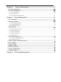
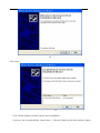
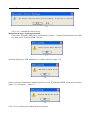
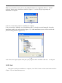
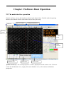
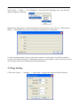
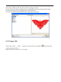
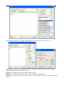
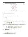
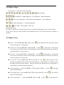
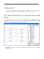
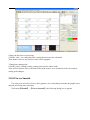
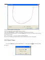
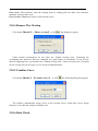
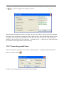
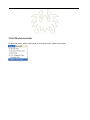
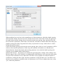
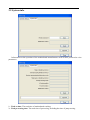
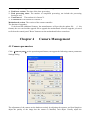
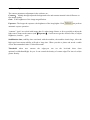
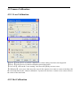
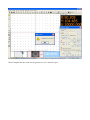
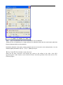
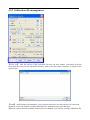
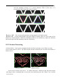
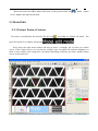
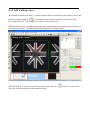
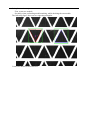
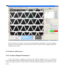
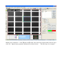
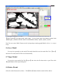
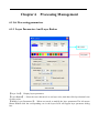
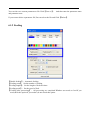
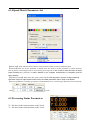
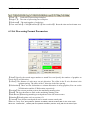
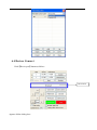
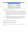
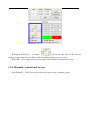
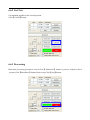
1
RDVision Laser cutting control Software
User
Manual
Shenzhen Ruida Technoloy Co.,Ltd.
Tel: 0086-075526066687
Fax:: 0086-075526066687
Addr:No.501,5/F,Building 2,Nanyou Tian'an Industry Park,Nanshan District,Shenzhen,Guangdong
Prov.
WEB: www.rd-acs.com
PostCode:518052
Note: The actual mode of operation and feature setting are inconsistent with this manual which
caused by the software upgrade.Please refer to software.
Contents
Contents...................................................................................................................... 2
Chapter 1 Overview...................................................................................................5
1.1 Visual cutting control system introduction......................................................................... 5
1.2 The composition of the visual cutting control system..................................................... 5
1.3 Software installation..............................................................................................................5
1.3.1 Start the installation................................................................................................................................. 5
1.3.2 Driver install and uninstall...................................................................................................................... 6
1.3.3 Exit...........................................................................................................................................................9
1.4
Software Features............................................................................................................. 10
Chapter 2 Software Basic Operation..................................................................... 11
2.1 The main interface operation............................................................................................. 11
2.2 Language settings and manufactures information........................................................... 12
2.3 Page Setting.......................................................................................................................... 13
2.4 Import and export files....................................................................................................... 14
2.4.1 Import File............................................................................................................................................. 14
2.4.2 Export File............................................................................................................................................. 15
2.4.3 File parameters setting...........................................................................................................................16
2.5 Basic graphics creation....................................................................................................... 17
2.6 Object Selection................................................................................................................... 20
2.7 Object Transformation....................................................................................................... 21
2.7.1 Object Mirror......................................................................................................................................21
2.7.2 Object Rotate...................................................................................................................................... 22
2.7.3 Place Object........................................................................................................................................... 22
2.8 Object Align......................................................................................................................... 23
2.9 Object View.......................................................................................................................... 23
2.10 Important Tool................................................................................................................... 24
2.10.1 Manual sorting and the set of cutting point and the cutting direction................................................ 24
2.10.2Curves Smooth..................................................................................................................................... 25
2.10.3 Check Closure......................................................................................................................................27
2.10.4 Remove The Overlap...........................................................................................................................28
2.10.5 Combine Curve....................................................................................................................................28
2.10.6 Data Check.......................................................................................................................................... 28
2.10.7 Generating parallel lines......................................................................................................................29
2.10.8 Model auto hide................................................................................................................................... 30
Chpater 3 System Settings...................................................................................... 31
3.1 General settings................................................................................................................... 31
3.2 System info........................................................................................................................... 33
Chapter 4
Camera Management.......................................................................34
4.1 Camera parameters............................................................................................................. 34
4.2 Camera Calibration:........................................................................................................... 36
4.2.1 Cross Calibration................................................................................................................................... 36
4.2.2 Dot Calibration...................................................................................................................................... 36
4.2.3 Calibration file management................................................................................................................. 41
Chapter 5 Mode Management.............................................................................43
5.1 Create Model........................................................................................................................43
5.2 Extract Featurs.................................................................................................................... 43
5.2.1 Select Feature Region............................................................................................................................43
5.2.2 Set Model Parameters............................................................................................................................44
5.2.3 Feature Processing.................................................................................................................................45
5.3 Model Edit............................................................................................................................ 46
5.3.1 Extract Feature Contour........................................................................................................................ 46
5.3.2 Edit Cutting Curve...................................................................................................................................1
5.3.3 Import Cut Contour................................................................................................................................. 3
5.3.4 Copy Cut Contour....................................................................................................................................3
5.3.5 Multi-Models........................................................................................................................................... 3
5.4 Contour And Layers.............................................................................................................. 2
5.4.1 Contour Output Parameters..................................................................................................................... 2
5.4.2 Set Contour Layer....................................................................................................................................4
5.5 Splice Model And Multi-Features........................................................................................ 4
5.6 Save Model............................................................................................................................. 7
5.7 Open Model............................................................................................................................ 7
5.8 Delete Model.......................................................................................................................... 7
5.9 Delete All Model.....................................................................................................................8
5.10 Save Model Image............................................................................................................... 8
5.11 Import Image....................................................................................................................... 8
Chapter 6 Processing Management...................................................................... 9
6.1 Set Processing parameters.................................................................................................... 9
6.1.1 Layer Parameters And Layer Button.......................................................................................................9
6.1.2 Feeding...................................................................................................................................................11
6.1.3 Path Optimize........................................................................................................................................ 12
6.1.4Speed Match Parameters Set.................................................................................................................. 13
6.2 Processing Status Parameters............................................................................................ 13
6.3 Set Processing Format Parameters.................................................................................... 14
6.4 Devices Connect................................................................................................................... 15
6.5 Control single-axis motion、Back to zero......................................................................... 16
6.5.1 Manually control single-axis motion.....................................................................................................16
6.5.2 Manually control back to zero...............................................................................................................17
6.6 Processing and Simulate processing.................................................................................. 18
6.6.1 Simulate processing...............................................................................................................................18
6.6.2 Cut Test.................................................................................................................................................. 19
6.6.3 Processing.............................................................................................................................................. 19
Chapter 1 Overview
1.1 Visual cutting control system introduction
Visual cutting control system (RDVision) is cutting system based on intelligent target
recognition. This system is mainly composed of PCI motion control card and CCD industrial
camera. Combined with image processing algorithm for target image feature extraction and
target recognition and finish cutting work by rtificial cut outline. The system operating software
control card and the upper machine by Ethernet or USB interface for communication.
This system user friendly interface, stable performance, simple operation, suitable for
large-format array type graphics cutting, such as trademark cutting field.
1.2 The composition of the visual cutting control system
Control system consists of two parts, hardware and software;
Of hardware equipment as shown in figure 1.1
Project
Control card
USB cable, network cable
Camera
Number
One
One
One
Description
Many USB and Network port
Within three meters in length
Including lens, lights, transmission
line and Other accessories
1.1
Software is RDVisionSetUp
1.3 Software installation
Software installation and system hardware configuration requirements:
(1) running on Windows xp and above version operating system, it is recommended to use the
Windows xp.
2 CPU 586 above, it is recommended that the P P Ⅳ Ⅲ or above.
(3) it is recommended to use more than 1 gb of memory.
1.3.1 Start the installation
Double-click the install directory RDVisionSetUp. Exe icon, a dialog box (figure 1.2) as
follows:
1.2
Click on the "Install" button, to extract the replication is complete, Install the interface (figure
1.3).
1.3
1.3.2 Driver install and uninstall
Install and uninstall for the Camera driver:
Click install on the main interface (figure 1.3) 【Install camera】button, can appear in figure 1.4
installation interface
1.4
Click "next"
1.5
Click "finish" button to end the camera driver installation
If the user need to uninstall the camera driver ", click the install on the main interface (figure
1.3) 【uninstall camera】 button, can appear in figure 1.6 the interface:
1.6
Click "yes", uninstall the camera driver.
Motherboard driver install and uninstall:
Users click 【Install USB】on the main interface (figure 1.3) button. Remind connection USB
tip, make sure is connected USB, click ok.
1.7
And then displays the USB installation is complete interface (figure 1.8)
1.8
If the user need to uninstall the motherboard driver, click 【UnInstall USB】 on the main interface
(figure 1.3) will appears figure1.9:
1.9
Click "ok" to complete the mainboard driver uninstall.
The Software installation:
When users install the camera driver and motherboard driver is completed, click on "Install
software" button on the install main interface (figure 1.3) .and it will pop-up prompts the
installation is complete.
1.10
Click ok, visual cutting software installation is complete.
If the user needs to manually set the installation path. Can check the option"manually locate the
installation path"on the main interface (figure 1.3). In the installation process will occur after the
position setting interface (figure 1.11).
1.11
After choose the required path, click [OK], the program will be installed on the user set the path.
1.3.3 Exit
The System software installation is complete, click "Exit" button on the install main interface
(figure 1.3)to exit installation process.
1.4
Software Features
1. Compatible with AI, BMP, PLT, DXF, DST, and other graphics data format.
2. Can edit and typeset simple graphics, text, and import the data.
3. Layout and define the output sequence.
4. Can set the machining process and precision personally
5. It can realize processing path optimization function.
6. Suspension in the manufacturing process of processing.
7. According to the different requirements of processing can be set as a starting point, the work
path.
8. Compatible with many kinds of communication mode, the user can according to the actual
situation using USB port communication or network communication.
Chapter 2 Software Basic Operation
2.1 The main interface operation
Start the software, can see the interface as shown in the figure below. Familiar with the operating
interface, the software will be used for the basis of laser processing
Menu bar
System Toolbar
Cutting properties bar
Drawing
toolbar
Control
Panel
Main
Interface
Machine View
Model View
Camera View
【Main interface】: The current perspective is video, display data for the camera view. If need to
switch into the Machine view, simply click on the Machine view, will switch to the Machine
perspective:
Ditto, perspective can also switch to the Model View
As shown in figure:
as the switch on the control panel module management. Each
model manages the important operating parameters and related functions.
【Menu bar】: the menu bar file, edit, drawing, setup, processing, view and help seven functions
menu items.
【Cutting properties bar】: mainly is the basic attribute of graphics, contains graphic location, size,
template basic properties such as zoom, and processing sequence number.
【System toolbar】: toolbar buttons for the most commonly used features, most of these options
from the menu bar.
【Drawing toolbar】: when the system default is located in the work area on the left. On the
drawing toolbar placed often use the editing tools, can undertake various edit operation to need to
edit the object.
【Control panel】:Control panel and main implementation of some commonly used operation and
Settings.
2.2 Language settings and manufactures information
In addition to the application installation process can set the language type of software, in use
process also can switch different languages.
Click "menu" - > "Help" - > "语言/Language", select the desired Language type, can realize the
display Language switching.
Manufacturer information, so that manufacturers provide a better service for you. Click [menu] - >
[help] - > [About RDVision], can be according to manufacturer's information.
In "about prompt interface" below is the current software version number. In different software
version, or the function interface. Through the software version number, can be convenient to users
in need help contact and communication with manufacturer.
2.3 Page Setting
Click on the "menu" - > "Settings" - > "page setup", to appear the interface for the following:
[Page width]: view page width, size of the X wide general Settings for the machine.
[Page height]: high view page, the Y wide general Settings for the machine size.
Usually, if the PC is connected to main board, the software will automatically gets the current
machine working level, as the page size. Under the condition of PC is not connected to the
motherboard, or the user needs to define your own page size (e.g., according to the material to set
the page size), can use the page setup to reconfigure the page size.
[keyboard] : the software can be through the up and down or so key keyboard to adjust the
positions of the graphics in the view.
According to a direction, moving distance = 【Adjust distance 】;
Press the SHIFT key and press a key direction, moving distance =【Adjust ratio】*【Adjust distance】;
Press the Ctrl key and press the direction key, graphics rotation Angle = 【Adjust Angle】 ;
Press Ctrl + Shift and at the same time press the direction key, the graphics rotation Angle =
【Adjust Angle】 *【Adjust ratio】
2.4 Import and export files
Since this software is used. The RLD format file. Need other file format when making or editing
done through import, derived by save as other file format data. Import the file formats supported:
DXF, ai, PLT, DST, DSB... And so on; The exported file format support: PLT.
2.4.1 Import File
Click on the "menu" - > [file] - > [imported], or click on the import icon
as shown.
Choose the appropriate file, click on the "Open" button.
. Will display interface,
If selected to 【Preview】, can choose files in an image of a file.
For vector data, the data according to the corresponding hierarchical description file format
automatically imported into the RDCAM corresponding layer.
For some special file like DST/DSB will be import the current layer
2.4.2 Export File
Click on the "menu" - > [file] - > [export] or click on the icon is deduced
export operation interface;
Input the file name, then click "save" button.
. Then show that
2.4.3 File parameters setting
【PLT Precision】According to the precision of the original PLT file to choose the appropriate
import units
【DXF Unit】Software default DXF import unit is mm. If there is an import DXF data size does not
agree with the original graphics, may be caused by unit does not match. Optional data unit is mm,
cm, inch, custom, when choose the custom, any user set up a unit of data in DXF file corresponding
to the RDCAM software in millimeters.
【Import Dxf text info】When the user need only within the Dxf graphics information, without the
need for a file in the text message, are not checked
【curve smooth】Vector file import, automatic smooth not smooth the curve of the original
graphics. For original graphics itself relatively smooth or need to repeatedly adjust the best
smoothing effect, are not checked, reduce import processing time. Dealt with after file imports.
【Auto close curves 】According to the close tolerance automatically checks and closed curve
【Combine lines】According to the merger of tolerance, automatic connection curve
【Velocity Unit】
Speed unit is mm/SEC, m/points two kinds, we can choose according to the habits, the selected
interface about speed parameter units will change accordingly.
2.5 Basic graphics creation
【Node edit】
Click on the "menu" - > "Draw" - > "node editor", or click the edit toolbar
the screen, click the mouse at any position, can draw the point.
, drag the mouse on
【Line】
Click menu【Draw】->【Line】,or click Edit toolbar
,drag the mouse on the screen you
can draw an arbitrary line 。 Press the “Ctrl” key while dragging the mouse to draw
horizontal or vertical line.
【Polyline】
Click menu【Draw】->【Polyline】,or click Edit toolbar
。Drag the mouse on the screen
And you can draw an arbitrary polyline.
【Bezier】Click[Draw]->[ Bezier]or click the Edit toolbar
.
The process of drawing refer to [Polyline] process.
Difference is that when you insert the middle point and hold down the left mouse button and
drag to adjust the curve control points.
【Rectangle】
Click menu【Draw】->【Rectangle】,or click Edit toolbar
。Drag the mouse on the
screen you can draw an arbitrary size rectangle.
Press the “Ctrl” key while dragging the mouse to draw square.
【Ellipse】
Click menu【Draw】->【Ellipse】,or click Edit toolbar
。Drag the mouse on the screen
you can draw an arbitrary size ellipse.
Press the “Ctrl” key while dragging the mouse to draw round.
【Edit text】
Click on the "menu" - > "Draw" - > [text], r click Edit toolbar
and then click on the plot in
any position, the pop-up text input dialog box.
Choose fonts, enter text, then set the word is high, the word width, line spacing, word spacing.
Click [Ok] to go again
Software also supports variable text, the so-called variable text, the text is need to change according
to certain rules, every output processing, text automatically change again. System support type text
with date and serial number.
Every time date variables are processing in the current system time of the current computer output.
Software provides a variety of date format for the user to choose from.
Users can set date migration, also have daily/monthly/yearly 3 kinds. Such as on product shelf life
can be used on the packaging.
Serial number variable can be digital serial number (0-9) Numbers or letters (a-z or a-z).
Suppose you want to processing ABC0001DEF repeatedly, ABC0002DEF, ABC003DEF until
ABC9999DEF such a set of serial number.
[Prefic]: serial number prefix, case ABC's leading strings.
[Suffic]: serial number of the suffix, DEF in the example is after the string.
[Start SN] : to specify from which serial number to start processing, case 0001 is the starting serial
number.
[Current SN] : the current processing to which the serial number, can also be used to specify the
current processing which serial number. If when processing a set of serial Numbers, leaks,
processing in one, can be processing, by specifying the serial number instead of setting start serial
number, because in some cases a set of serial number requires repeated processing, namely to after
a certain number, need to return to start serial number to start processing.
[SN Inc] :can specify the serial number on the number of intervals. Case to processing, from 0001
to 0001 in turn serial number, the increment of 1.
If you just need to output an even or odd number serial number, you can set increment of 2.
[Enable reset]: when machining to reset the serial number, serial number will be automatically
reset to the current serial number start serial number.
Case requires repeated processing sequence number from 0001 to 9999, therefore can specify 9999
for reset the serial number, after when processing the 9999 serial number, text will automatically
change to 0001
[Enable prefix ZERO]:without enabling leading zeros, then the system will automatically remove
the serial number of the first nonzero Numbers in front of zero. As the serial number of the case, if
there is no can make leading zeros that ABC0001DEF will become ABC1DEF. But it is worth
noting that if we want to output the sequence number is ABC1DEF, ABC2DEF until ABC9999DEF,
we cannot pass will be set to start serial number 1, but by eliminating, enabling leading zeros .this
is because the set start serial number in a specified sequence number from which one number, also
specifies the number of significant digits, such as to start the serial number is set to 1, the serial
number of the change order is: 1,2,3,4,5,6,7,8,9,0,1,2,3,4,5... The serial number will not change to
10, because only one serial number of the effective bits.
[Enable SN array] in the form of arrays, one-time processing multiple serial Numbers.
Such as:
0001 0002 0003
0010 0011 0002
0006 0005 0004 after machining this batch number, directly to the next set of
0015 0014 0013
0007 0008 0009
0016 0017 0008
2.6 Object Selection
In the process of drawing and edit graphics,first of all is to select the object.
When the object is being selected,in the center of this object will have a shaped mark“ × ” ,and
surrounded by eight control points.
Click menu【Draw】->【Select】,or click Edit Bar
,switch to status“Select”。Under this
status,you can select object.The following are five kinds of method of selecting:
◆
Click menu【Edit】->【Select All】(Shortcuts Ctrl+A), select all objects。
◆
Click mouse on the screen to select single object
◆ Select object using select box
Press the mouse and drag, as long as the box come into contact with the object will be selected。
◆ Increased select object/minus select object
Increase select:Press “Shift” key, click or box select to increase select object.
Minus select:Press “Shift” key, click or box select the selected object.
2.7 Object Transformation
Transformation of object mainly include: object location 、 orientation and size. But does not
change the basic shape of the object and its characteristics.
Transformation of object for users, provides a convenient user interface. User can mirror and
rotation through
within the draw toolbar.
You can also use the Object Properties toolbar, transformation tools to transform and copy the
graphics.
2.7.1
Object Mirror
Object image is flip the selected object in the horizontal or vertical direction.
Click Edit Bar
,flip the selected object horizontal.
Click Edit Bar
,flip the selected object vertical.
Or through the lens to the transform tools, horizontal and vertical direction to the lens, and copy
2.7.2
Object Rotate
Click Edit Bar
,will pop up the dialog of rotate angel setting.
Set rotate angle and click the button【OK】.
If you want to drag rotation, set rotate angle 0,and determine.
Dragging the mouse to adjust the rotate angle, in the dragging process, there will be followed by
rotating wire-frame outline.
Or directly enter the rotation angle in the Object Properties toolbar.
2.7.3 Place Object
Place the object is to facilitate the view or orientation. The following tools are provided by
software:
, selected object will be placed in the center of the page, that is the object center coincides
with the center of the page.
, Selected object will be placed on the page left, upper right, lower right, lower
left, upper left corner of the object, upper right, lower right, lower left and upper left corner, top
right, bottom right, bottom left corner of coincidence.
2.8 Object Align
Select objects,click tools on the Align Bar
.Whick include:
Left alignment、Right alignment、Top alignment、Bottom alignment
Vertical center alignment、Horizontal center alignment、center alignment
Horizontal equidistance、Vertical equidistance
Same width、Same height、Same size.
Benchmark object:
If you press “Shift”key and select object one by one,zhen the benchmark object is the last object.
If you select object by select box,then zhe benchmark object is the object which curve number in
the final.
2.9 Object View
◆ Move:Click menu【Edit】->【Move】,or click
。Then hold down the left mouse button
in the drawing area,and drag pan.
◆ Zoom Out:Click menu【Edit】->【ZoomOut】,or click
。Each click it,the drawing
area zoom out once.Move mouse to the drawing area and click,each click,mouse position as
center drawing area zoom out once.
◆ Zoom In:Click menu【Edit】->【ZoomIn】,or click
。Each click it,the drawing
area zoom in once.Move mouse to the drawing area and click,each click,mouse position as
center drawing area zoom in once .
◆ View Select:Click menu【Edit】->【View Select】,or click
。Move the mouse to the
drawing area,hold down the left mouse button and drag,a dash border box will show in the
drawing area,release mouse button,then the region in the dash border box will display in
the drawing area with the largest proportion.
◆ View Page Frame:Click menu【Edit】->【View Page Frame】,or click
。The page
frame will full display.
◆ View Data Frame:Click menu【Edit】->【View Data Frame】,or click
。The selected
objects will full display
◆ View Feature Data : Click menu【Edit】->【View All】,or click
。Feature data will
be display.
2.10 Important Tool
Here are some frequently used tools. Using these important tools, can make the current
document in the graphics more orderly, and make the processing of output more fast.
2.10.1 Manual sorting and the set of cutting point and the cutting
direction
Software provides users a convenient tool for the manual sorting. Select 【Edit】->【Set cutting
property】. Cutting property dialog box will pop up. All with manual sorting, and cut points, cutting
the direction of the settings in this dialog box can be completed.
[ShowPath]First check the “showpath”, it will display the current graphics cutting order and the
cutting direction.
Change the direction of processing
Click the "edit" / set cutting direction, cutting direction into the edit mode.
Then double-click on any position on the selected graphic.
"Change the cutting point"
Click the [edit] / [setting] cutting, cutting point into the editor mode.
Then select to edit the curves, the node at the point want to set a cut double-click can complete
cutting point changes
2.10.2Curves Smooth
For some poor precision of curve, their graphics, curve smoothing can make the graphic more
smooth, processing more smoothly.
Click menu【Handle】->【Curves Smooth】,the following dialog box is appears.
Drag smoothness, click 【Apply】 button, the screen will be displayed before the smooth and
smooth curve, easy to compare.
One of the black curve for the original curve, after the red curve is smooth curve.
You can view the graphics with drag mouse.
You can zoom in/zoom out the graphics with scroll wheel.
Click button【FullFrame】,graphics will shown in the dialog box for largest.
After get satisfied smoothing effect,click button【Apply】,curves will processing smooth according
to smoothness settings.
Select “Direct smooth” , you can use another smoothing method.
The choice of smoothing method should be changed with the needs of the actual graphic.
2.10.3 Check Closure
Click menu【Handle】->【Curve auto close】,or click System Bar
box appears.
,the following dialog
Close error: When distance from the starting point to ending point less than close tolerance,
automatic closing of the curve.
Force to close: Mandatory closure of all selected curves.
2.10.4 Remove The Overlap
Click menu【Handle】->【Delete overlap】,or click
,the dialog box appear.
Under normal circumstances do not select the “Enable Overlap error”. Removing the
overlapping lines when two lines are compared to a good degree of coincidence. If you need to
delete overlapping lines, you should select “Enable Overlap error”, and set overlap error. Generally
do not overlap error set too large, so as to avoid accidental deletion.
2.10.5 Combine Curve
Click menu【Handle】 /【Combine Curve】,or click
,the following dialog box appears.
The software automatically merge curves in the selected curves, when these curves merge
tolerance is less than the setting of combine error.
2.10.6 Data Check
After the selected graphic to check, click the [menu] - > [Handle / [data check], or click toolbar
icon
, the system will appear the following interface
Data checking, integrates the closure checking, since the cross check overlap, cross check and data
checking. Users can choose according to need to check the item, after data detected problem, in the
dialog box on the right side tip problem has been detected and at the same time will question the
graphics in the selected state. Over checking - > eliminate errors - > check process, until all the data
are conform to the requirements of the processing.
2.10.7 Generating parallel lines
Selected to generate parallel lines of the data, click the [menu] - > [handle] / [generated parallel
lines ],or click the toobar
.
Red line as the original graphics, green line for the graphics.
2.10.8 Model auto hide
In ‘Model edit mode’, hidden cutting data; In ‘cutting edit mode’, hidden feature data.
Chpater 3 System Settings
Before output graphics , required to determine whether the system settings are correct.Click
menu【Config】->【System Setting】
3.1 General settings
Axis Mirror
Generally, Axis direction of mirror is based on the actual location of the limit or home of
machine.
The default coordinate system if Descartes coordinate system, and zero in the bottom left.
If the zero point of the machine is top left, then X-Axis do not need to mirror, but Y-Axis need
to mirror.
If the zero point of the machine is top right, then both X-Axis and Y-Axis are all need to mirror.
In addition, this function can also use to other application for mirror.
Small Circle Speed Limit
On processing work,the software automatically determine whether the current round need to
limit speed ,then according to the diameter size of the circle to determine the speed. If parameter
configuration appropriate ,will greatly enhance the quality of small round. Click button【Add】,
【Delete】, 【Modify】 to configuration.
Small circle is less than speed of the rules limiting the list of small round circle of minimum
radius, minimum radius circle at the speed of the output of the corresponding.
If the speed greater than maximum speed limit list the speed round, the speed only associated
with the speed of the layer.
If the speed is in the list, set the output speed by list.
If the request received by limiting layer parameters faster than the speed set in the layer, press
the speed of the output layer.
1. Add backlash
Click the Add button, the screen will pop up as shown in Figure
Set speed and backlash, click OK, the value to be inserted into the list of backlash. (2) 2.Modify
backlash
Double-click the left mouse button scanning (reverse gap) need to modify the reverse block
entry clearance, then the pop-up screen shown in Figure.
In the interface can modify the current speed of the corresponding backlash.
(3) Remove backlash
Right-click scanning (reverse gap) block in the backlash to delete the item, then click the
【Delete】button
【Double spacing】
When machines have two laser in the manufacturer of other parameters, check the double spacing,
and fill out the distance between two laser, distance between two laser head is fixed, the spacing is
inevitable when machine design, please accurately measure the spacing value, and then fill in the
box in the above parameters. If the value is not accurate, will lead to a double shift each cutting out
graphics spacing was faulty. In general, the value you just need to set up a, unless there is a limit
switch the mobile location.
Check after double spacing and set up the correct spacing value, click on "write" parameters, will be
written to the controller parameters, in this way, the controller will enable a two-headed move
mutual function; On the other hand, when writing parameter is not checked double spacing, this
controller is not enabled double shift function.
[double shift each 】 : the purpose is to shorten the processing time, cutting a laser cutting is less
than the edge of wide, if the controller is enabled double shift function, at the same time must make
can open XYU triaxial boot reset, and let the XYU three axis in reliable reset when the phone is
switched on, looking for their origin. In factory parameters, will XYU three axis "can make reset"
checked, write parameters, and then in the user preferences, in XYZ axis whether boot reset, select
"yes", and write parameters.
3.2 System info
Information on the operation of the motherboard manufacturers need to enter password to view
parameters.
1> Total on time: The total time of motherboard working
2> Total processing time: The total time of processing ,including the time of jump moving.
3> Previous processing time: The time of the last processing
4> Total laser on time: The time of the laser processing
5> Total processing times: The number of completed processing, not include the processing
forcing to end.
6> X total travel: The total travel of motor X.
7> Y total travel: The total travel of motor Y.
Motherboard version: The version of the current controller.
The function of upgrades:
If the board has additional features, the manufacturers will provide the update file
(*. bin
format), the user can load the upgrade file to upgrade the motherboard. After the upgrade, you need
to click on the control panel "Reset" button reset the motherboard before normal use.
Chapter 4
Camera Management
4.1 Camera parameters
Click 【camera para】on the operation panel button, can appear the following camera parameters
Settings dialog
The adjustment of the camera on the hardware mainly by adjusting the aperture and focal length to
adjust the quality of the image but the camera is installed, can't adjust. Usually adjust the
environment light.
The camera parameters adjustment in the software are:
Contrast: Mainly through adjust the background color and contrast material color difference to
fine image quality.
Gain:is the brightness of the image magnification.
Exposure:The longer the exposure, the brightness of the imag higher.Click
can perform
automatic expose operation。
"contrast", "gain" are to deal with image data. So when image fainter, as far as possible to adjust the
light source (lamp on the camera )and【Exposure】, if still can not get the desired effect, to adjust
brightness, contrast , gain .
Stabilization time, stability time associated with the machine, the machine inertia large, After the
high speed movement stability will take a long time. When you take a photo and needs a stable
vision. Recommended value is 300 milliseconds.
Threshold: when user extracts the edges,you can set the level.and there three
options(Low\Medium\High) for you. It can control the density of extract-edges.The lower level,the
greater density.
4.2 Camera Calibration:
4.2.1 Cross Calibration
【Speed 】In the process of camera calibration, or when cutting cross laser moving speed.
【Power 】In the process of camera calibration processing power.
【Cut Cross】, click on the "cross cutting", the laser will quickly cut out a cross.
【Calibration】 : cut a cross, then move the cross in the camera view center to center coincides with
the cross and click on the "camera calibration". System will also have a camera view center offset to
the center of the laser head.
4.2.2 Dot Calibration
【Width 】The width of the camera view, after installation of the camera, users fill in according to
the actual data.
【Height 】The height of the camera view, after installation of the camera, users fill in according to
the actual data.
【Interval】Rbis, laser make a point of light time.
【Space】Set the distance between two points
【Dot】 Click on the "Dot" button, the system will be based on user fill in the camera view the size,
print out the M * N could be covered with the camera point of view.
【Correct 】Use laser to play good outlets on the camera right in the middle of the visible area,
click on the "correction" button, the camera calibration can be realized. The following figure:
If the correction is successful, system prompt correction of success;
If it fails, the system prompt correction failure. Need to repeated correction, until success.
Note:Complete the Dot Calibration,Suggest that do Cross calibration again.
【X】、【Y】This parameters are set the compensation of cross calibration.
【 Ratio 】 There is tinydifference in height between the calibration plane and the actual match plane.Can
improve cutting precision by this parameter.
Note:When calibration many times, cutting operation also can not meet the user needs precision. You can
manually adjust parameters of【X】、【Y】、【Ratio】in step 4.
【Clear Camera】Clear the data on the video area.
When the dot after correction, will display the extract to the outlets in the video. Area click
operation panel "video" button, can be removed. Please check the position of the video area on The
following figure:
4.2.3 Calibration file management
【 Save As 】 : after the success of the correction, the user can save another "correction" keep the
correction files saved to the specified directory, and set the file name. Interface as shown in the
figure below:
【Load】: under normal circumstances, every time do not need to use the software for correction
operation. Users can load the existing calibration file, implement correction function.
When the camera and the machine position has not changed, just load the existing calibration file.
Click on the "load file", issue a file dialog box. Find correction need to load the file, and click
"open" button to complete loading operation. Interface is as follows:
【Reset】:Camera calibration, the calibration results are not ideal. Users need to be corrected
again .Before the next correction,user must clear the calibration object. In this case, click the
“Reset” to clear the calibration object.
Chapter 5
Mode Management
5.1 Create Model
Move the camera filed center of view to the center of the actual image.And then click【Create】
operation button.The system will prompt user to enter a name of the model.As shown below:
Enter a non-existing model name.Then click【OK】,a model carete successfully.
5.2 Extract Featurs
5.2.1 Select Feature Region
The sithching button of model editing mode
.It can be switched between “Model edit
mode ”and “Cutting edit mode”.
In the “Model edit mode”,Press down the right mouse button,Drag to draw a green rectangle
(Can draw multiple times).The area within the green rectangle is feature region.
Feature region selected Note:
1. Graph of the feature region,It must be a unique identifier of the unit target object.
2. In the feature region,The color of Graphics and background must be different.
3. The larger feature region,the longer matching time.So don’t choose too large region.
4. If model is big model,the feature region cannot be located on the splicing clearance.
5.2.2 Set Model Parameters
【 Smooth 】 : The higher smoothing coefficient,the less scattered points of feature region be
extracted.(Detailed Description please refer to chapter 5.2.3)。
【 Similarity 】 : the matching score of model and actual graphic.The higher score,the more
similar.The value of similarity directly affect the matching quality.
【 Overlap 】 : The overlap percentage of two target object envelope rectangular.This parameter
controls whether targets that has overlapping part will be matched .
【Angle】:Set the angle range of model rotation search.For example,the value set to 180.In the
matching process,search angle rangle is -180~180.
According to actual needs to set the search angle.The larger search angle,the longer
matching time required.If the user does not need to set this parameter,and you
should remove the check.
As shown below,There are two opposite triangles.If you use a model matching.You
must check this option and set the search angle to 180
.That
software can find the two opposite triangles. However, in the process of rotation
match,increase the amount of computation and slowing the speed of matching.
And the matching accuracy of a certain reduction. Thus, in this case, it is
recommended that using multi-model to match.
【Apply to all】:The current model parameter settings applied to all other models.
【Match test】:Current model match to the target image of camera field view. Test results will be
returned as results-interface. When the matching results are not satisfactory, adjust the similarity
and search-angle until the matching results are satisfactory.
5.2.3 Feature Processing
As shown below,In the green rectangular box,the red lines are feature curves.There are some
excess scatter-points or curves。By improving the smooth coefficient,user can reduce the number of
feature curves.
(Smooth 50%)
(Smooth 100%)
If users need to delete some curves,In “Model edit mode”, Hold down the left mouse button
and drag to draw a rectangle that to select the curves.And then press the “Delete” key to delete
excess curves.
【Screen Feature curves】In’Model edit mode’,Click system toolbar icon
。Select feature
curves’ length is less than the set value.
5.3 Model Edit
5.3.1 Extract Feature Contour
First,select a model(check the model).Click the icon
top-left of main-view window will prompt.
on toolbar. In “Model edit mode”, The
.
Press down the right mouse button and drag to draw a rectangle. the red lines are feature
curves. If the feature curves are not obvious enough, users can adjust the ambient brightness to
make a clear outline of the image.Also can adjust smoothing coefficient, get better quality feature
curves.As shown below:
5.3.2 Edit Cutting Curve
【Contour】In’Model edit mode ’, Feature contour has been existed.First select feature-curves, and
then click system toolbar icon
, It can automatically generate cutting curve contour. Then
In“Cutting edit mode”, Edit cutting curves.Please refer to section 2.4 .
【Manual Paint Cutting Curve】In“Cutting edit mode”, Edit cutting curves.Please refer to section 2.4 .
In “Cutting edit mode”, The blue lines are the cutting curves.as shown below:
【Node Edit】In “Cutting edit mode”,Click the “Node Edit” tool
Next,user can add nodes,delete nodes,and node drag.
,and user can edit nodes。
Drag node to change the graphical outline;
Double-click the left mouse button on the contour curve to add a node;
Double-click the left mouse button on the node to delete a single node; Marquee multiple
nodes and press the “Delete” key to delete multiple nodes.
After editing, as shown below:
By the operation of node edit.user can adjust graphic outline. Graphic contour transformation
processing in order to achieve the user's needs. Details please refer to sections 2.6 and 2.9
Supports importing contour from other graphics software (AutoCAD, Adobe Illustrator,
CorelDraw) drawn to the model. Details please refer to sections 5.3.3
5.3.3 Import Cut Contour
In “Cutting edit mode”,Import cut contour.
In “Cutting edit mode”,Click【File】->【Import】,Appears open file dialog box.Next select file
and then 【Open】As shown below:
Import file to the model, the mouse to drag the contour curve placed at the right position.
Fine-tuning can also be achieved by the top , bottom ,left and right keyboard keys.Details please
refer to section 2 . 3
5.3.4 Copy Cut Contour
It can copy cut contour between different model.
First fo all, In “Cutting edit mode” of ‘Mode A’.Select the cut contour and press down Ctrl+C
Next,Switch to ‘Model B’,Press down Ctrl + V ,The copy opteration is completed.
5.3.5 Multi-Models
In the same target image contains different graphics,this software provides multi-models
matching-search function.
Its implementation steps:
First, create two models;
Secondly, when performing model matching, while checking the two models.
The following figure, there are two opposing triangular.
Create two models,as shown below:
Then,Check the two models can be achieveed multi-models matching.In the actual matching
process, the inverted triangle with the inverted model to match and the upright triangle the
upright model to match.
5.4 Contour And Layers
5.4.1 Contour Output Parameters
In the same batch of graphics processing, The different graphics need to set different
processing parameters.Processing parameter corresponds to the color layers. Layer parameters is the
contour of output parameters. Layer parameters can be modified according to user needs.As shown
below:
Modify layer parameters:Click【Work para】button, The left mouse button double-click the layer
color list。Appears layer parameter dialog box.As shown below:(The blue layer, for example)
5.4.2 Set Contour Layer
Different layers with different colors. Different layers have different parameters. In the output
of the processing, Different contours output in the same processing parameters, just all contours set
to the same color(That the same layer)。
Different contours output in different processing parameters, just set contours to different color
(That the different layer)
【 Set Contour Layer 】 : In “Cutting edit mode”,Select the contour.Click the layer button.As
shownbelow:
图层列表
图层按钮
Note:For more details about layers,Please refer to section 6.1.1
5.5 Splice Model And Multi-Features
First,Click【Splicing】,Appears follow dialog box:
The Splicing operation requires two coordinates of graph diagonal.
Secondly,Move the center of camera filed view to upper left corner of graphic.Then Click【Set point
1】.As shown below:
Third,Move the center of camera filed view to lower-right corner.Then Click【Set point 2】.
As shown below:
Fourth:Click【Start】,Splicing results as shown below:
Fifth: If need to update the local area, Click the leftmouse button and drag to select area need to update. And
click the"Update” button.
Completely splice , And click the"Ok” button.It will automaticlly create a model.
Splicing graphic as follows:
【Multi-Features】For a larger model(Splice image), You can choose many of its features to locate. In the
【Model type】 parameter sets the number of characteristics: Namal, 2 points, 3 points, 4 points.
Note:You can create Multi-Features mode by importing scanning graph,Details refer to ‘5.11 Import
Image’
5.6 Save Model
User need to repeatedly use the model.The model should be saved as model file.Click 【Save】
and enter file name,model will be saved automaticlly.
5.7 Open Model
User need to open model file,Click【Open】and select the file that needs to open.Then click
【Open】button on the open-dialog box.
5.8 Delete Model
Select the model that needs to delete,Click【Delete】button that the model will be deltete.
5.9 Delete All Model
This operation button will delete all model,Clieck【Del all】button that all model will be delete.
5.10 Save Model Image
Save the model image as a picture file, the picture file can be imported into other graphics
software. Draw Cutting contour and save it as a data file. Our software provides import operation
for cutting contour data.
5.11 Import Image
Splice larger image,also can use scanner to scan the larger image.Click the 【 Import Image 】
function button to import scanning graph and create Multi-Features model.
Chapter 6
Processing Management
6.1 Set Processing parameters
6.1.1 Layer Parameters And Layer Button
图层列表
图层按钮
【Layer List】:Display layers paraneters.
【Layer Button】:Select the curve that need s to set layer color, And then click layer button.It can
set layer color.
【 Modify Layer Parameters】: When user needs to modify the layer parameters.The left mouse
button Double-click the corresponding row in the layers list.It will appear layer parameter dialog
box.
User can modify the parameters in the “Layer parameter” dialog box.You can load parameters from
parameter library if parameters file have been saved, previously.
Click【Load parameters from library】,Appears follow dialog:
Select parameter file from the library , And then Click 【 Load 】 , Complete the parameters
load.operation.
You can also save current parameter to file.Click【Save as】, And then enter the parameter name
and parameter note.
If you want to delete a parameter file,You can select the file and Click【Delete】.
6.1.2 Feeding
【Enable feeding】:Automatic feeding
【Feeding num】:Set the number of feeding.
【feeding length】:Set the length of feed each time.
【feeding speed】:Set the speed of feed.
【 Feeding after processing 】 : All processing are completed.Whether user needs to feed.If you
need,check this option.If you needn’t,do not check this option.
6.1.3 Path Optimize
【Path Optimise】:Just optimized only once matching results.
【Block height】:Optimize the processing data, the block can reduce the difficulty and optimization
efficiency. The overall data is divided into a plurality of partial data blocks
according to the block-height. In the optimization, the local data block as a unit for
optimization.
【 Inside to outside 】 : If there are inclusion relationship in the cutting path.User can set the
processing path to “Inside to outside”.(check“Inside to outside”)。
【Dir】:In the path optimization processing,the direction of setting is the overall path direction.
6.1.4Speed Match Parameters Set
【Match num】In the effective filed of camera view.The total number of existing matching-object.
【 Timeout 】 When you set the parameter of ‘Match num’,You need to set this parameter to control matching
time.In process of matching,In order to avoid waiting for a long time or lack of time to cause the failure of target
image matching.This parameter is mainly affected by the template characteristics of complexity and the
target quantity。
【Speed match mode】When select this option.system will take fast algorithm in process of target-matching.
Note:when select the option’Speed match mode’,The Model parameters option ‘Angle’ must disable.
【Serrch type】Define searching type.Options include’Stadard array’,’Custom angle’,Dynamic search.It combine
with
6.2 Processing Status Parameters
X:The laser head current position on the X-axis
Y:The laser head current position on the Y-axis
to work.
U:The laser head current position on the U-axis
【Total T】: Total time of processing workpiece.
【Single T】:The time of processing one workpiece.
【Work num】: The total number of workpiece.
【Clear work info】:Click【Work Para】->【Clear work info】,Reset the time and work num zero.
6.3 Set Processing Format Parameters
【 Num 】 Specify the search target number to match.You can Specify the number of graphics on
X-axis and Y-axis direction .
【 Offset 】 The distance of each move on axis direction. The offset in the X axis direction is the
column spacing. The offset of the Y direction is the line spacing.
【Dislocation】There are line dislocation or column dislocation in array-graphics,You can set the
X-Dislocation and the Y-Dislocation respectively.
【Position】Set current position-point as the machining-strating point.
【Back】The laser head moves back to the machining-starting point。
【Path Browse】Browsing matching-search path and view the camera zones.
【Simulate】Details pelase refer to section 6.5.1
【Custom】User defines search path,It can be nested custom search path.
When set ‘Array first’,array path for systemic circulation, and the custom path for the minor cycle.
When set‘Custom first’,custom path for systemic circulation, and the array path for the minor cycle.
6.4 Devices Connect
Click【Device port】button,as follow:
Device Port
Appears follow dialog box:
There are two device connect ways:USB and Web. Click 【 Device port 】 button,Then set the
connection ways and select connection port.
【 USB 】 : If the computer is only connected to a laser device, you can set this option to
automatically. The software will automatically determine the connection interface to
the device. When the computer is connected to more than one laser equipment, you
need to first click on the 【Device Port】 button. In the dialog box, click [Search]
button. The search is completed, the drop-down list will be displayed the connected
currently device interface. User selects the desired device interface, can output to the
specified device.
【Web】: If the computer is only connected to a laser device ,You can directly input IP address
in the default device IP. When the computer is connected to more than one laser
equipment,Similar to the 【USB】. Find the device has been connected, and select
corresponding IP address of the device from the drop-down list.
6.5 Control single-axis motion、Back to zero
6.5.1 Manually control single-axis motion
Single-axis motion control, you can only control one axis motion, you can set distance, speed
of movement.
【 Stepping distance 】 : As shown :
Fill out the step value in the edit box.
Single-axis movements, in accordance with the stepping distance move as a unit.
【Speed】:Set a single-axis movement speed, user-defined movement speed value.
6.5.2 Manually control back to zero
Click【Home】,The XY axis will return to the origin of the coordinate system.
6.6 Processing and Simulate processing
6.6.1 Simulate processing
Processing data is ready, the user can simulate processing to preview machining results.
Click【Simulate】button,Starting the simulate processing.
Need to pause ,Click 【Start / Pause】button, Need to stop,Click 【Stop]】button.
6.6.2 Cut Test
Cut matching graphics at the current position.
Click【Cut test】button.
6.6.3 Processing
Determine processing parameters correct.Click 【 Start/Pause 】 button to process workpiece.Need
topause,Click【Start/Pause】button,Need to stop,Click【stop】button。
Note:【Match test】Details information please refer to 5.4.2
Thank you for using Shenzhen RuiDa Technology Co., Ltd. Products!All parts of the present
note, economic rights own by the Shenzhen RuiDa Technology Co., Ltd.. Without the permission of
our Company. Any unit or individual can not shall, copy or distribute the content in the
productmanual.If the content of this product information is changed.Please forgive without notice.
If users have any comments and suggestions while using this product and introductions, Please
call the Advisory.
Tel: 0086-075526066687
Fax:: 0086-075526066687
Addr:No.501,5/F,Building2,Nanyou
Tian'an
Industry
Park,Nanshan
District,Shenzhen,Guangdong Prov.
WEB: www.rd-acs.com