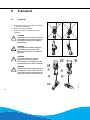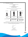
1
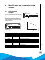
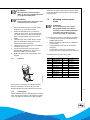
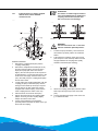
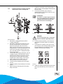
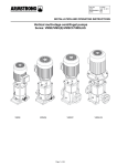
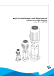
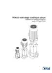
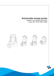
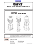
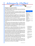
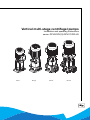
Vertical multi-stage centrifugal pumps Installation and operating instructions series: DPVE/DPV(S)/DPVCF/DPLHS DPVE DPV(S) DPVCF DPLHS Table of Contents 1 Manual Introduction 1.1 1.2 2 Identification, service and technical support 2.1 2.2 2.3 3 9 Setting up the pump............................................................................................................................. 16 Mounting a motor on the pump ............................................................................................................ 17 Electrical install .................................................................................................................................... 20 Commissioning .................................................................................................................................... 20 Operation 8.1 2 Transport.............................................................................................................................................. 14 Weight.................................................................................................................................................. 15 Storage................................................................................................................................................. 15 Installation instructions 7.1 7.2 7.3 7.4 8 General ................................................................................................................................................ 10 Intended use ........................................................................................................................................ 10 Working range.......................................................................................................................................11 Explosion safety................................................................................................................................... 12 Operation ............................................................................................................................................. 13 Transport 6.1 6.2 6.3 7 General .................................................................................................................................................. 8 Users...................................................................................................................................................... 8 Safety provisions.................................................................................................................................... 8 Safety precautions ................................................................................................................................. 9 Environmental aspects........................................................................................................................... 9 Pump Introduction 5.1 5.2 5.3 5.4 5.5 6 Terms of warranty .................................................................................................................................. 7 Safety and environment 4.1 4.2 4.3 4.4 4.5 5 Obtaining data and information .............................................................................................................. 5 Nominal current...................................................................................................................................... 6 Supplementary documentation .............................................................................................................. 6 Warranty 3.1 4 Preface................................................................................................................................................... 4 Icons and symbols ................................................................................................................................. 4 Operation ............................................................................................................................................. 22 Maintenance 9.1 9.2 9.3 9.4 Introduction .......................................................................................................................................... 23 Lubrication ........................................................................................................................................... 23 Maintaining the pump for an extended period of non-operation .......................................................... 23 Replace DPVE non-return valve .......................................................................................................... 23 10 Failures 10.1 Failure table ......................................................................................................................................... 24 11 Annexes 11.1 11.2 11.3 11.4 Spare part kits ...................................................................................................................................... 27 Technical specifications ....................................................................................................................... 42 Torques of coupling bolts - pos 914.01 ................................................................................................ 44 CE declaration of conformity................................................................................................................ 45 3 1 Manual Introduction 1.1 Preface This manual contains important information for reliable proper and efficient operation. Compliance with the operating instructions is of vital importance to ensure reliability and a long service life of the product and to avoid any risks. The first chapters contain information about this manual and safety in general. The following chapters provide information about normal use, installation, maintenance and repairs of the product. The annexes contain the technical data, the parts drawings and the declaration(s) of conformity. • • • • 1.2 Make yourself familiar with the content. Accurately follow the directions and instructions. Never change the sequence of the operations to be carried out. Keep this manual or a copy of it together with the logbook in a fixed place near the product which can be accessed by all personnel. Icons and symbols In this manual and in all accompanying documentation the following icons and symbols are used. WARNING Danger of electric Voltage. Safety sign according to IEC 417 - 5036 WARNING Operations or procedures, if carried out without caution, may cause personal injury or damage to the product. General hazard sign according to ISO 7000-0434 4 ATTENTION Is used to introduce safety instructions whose non-observance may lead to damage to the product and its functions. ENVIRONMENTAL INSTRUCTION Remarks with respect to the environment. 2 Identification, service and technical support 2.1 Obtaining data and information ID 2517/13062005 Q: H: P.req: Ser.Nr: P: n: 2517/13062005 The name plate indicates the type series / size, main operating data and identification number. Please quote this information (first two lines*) in all queries, repeat orders and particularly when ordering spare parts. If you need any additional information or instructions exceeding the scope of this manual or in case of damage please contact DP-Pumps's nearest customer service centre. duijvelaar pompen dp pumps Holland Pump without motor ID 2470/07052004 ID2446/13062005 duijvelaar pompen dp pumps Holland I nom: Ser.Nr: P: n: Pump with motor Q nom Indication DPV Meaning 4-40 Ca / Sic / EPDM PN Pump type* Serial number* S: / ser.nr. 19/2004/234567 19 Production week* 2004 Production year* 234567 Product identification (as built file)* Ca Rotating part mechanical seal (Carbon)* Sic Stationary part mechanical seal (Siliconcarbide)* EPDM Static sealing, O-rings (EPDM)* 10 Pressure class (flange) connection* 3 Q m /h - l/sec. - USGPM Nominal capacity (see Q/H curve above) H mWc - PSI Nominal head (see Q/H curve above) Inom1 A Nominal current ( see 2.2) n 1 Nominal rotation speed P kW - HP Installed motor power on the pump Preq kW - HP Required motor power for the pump 1. 2470/07052004 H: 2446/13062005 Q: H nom /min For pumps delivered with special motors no values are given (please use values as indicated on the motor plate). 5 DP-Pumps service department Kalkovenweg 13 2401 LJ Alphen a/d Rijn The Netherlands 2.2 Tel: +31 172 488325 Fax: +31 172 468930 Internet: www.dp-pumps.com E-mail: [email protected] ID 2446/13062005 duijvelaar pompen dp pumps Holland Nominal current The maximum allowable current of the motor is mentioned as I.max. on the motor plate. This maximum allowable current shows the maximum working range of the motor and can be used to protect the motor. WARNING Be careful in using it this way, because, not only the motor, but also the pump has to be protected in its application. Q: H: I nom: Ser.Nr: P: n: This current value can also be used to determine the proper electrical equipment such as variable frequency drive, main switch, wiring diameter etc. 2.3 Supplementary documentation Apart from this manual, the documentation given below is also available: Document Date/version Code General terms of delivery 10-1998 119 / 1998 Engineering Reference Book 11-2008 BE00000329 Technical Data 50Hz 07-2008 97004434 Technical Data 60Hz 07-2008 97004435 Technical Data 60Hz U.S. 12-2007 97004436 Motec operating instructions 09-2001 BA-8200-motec-frequency-inverters-V3-0.EM See also www.dp-pumps.com 6 On the pump plate (sleeve sticker) this "pump current at 400 Volts" will be mentioned as I nom. and can be used to pre-set the motor protection switch to protect the pump/motor combination. 2446/13062005 The following address data are available for service and technical support: 3 Warranty 3.1 Terms of warranty The warranty period is settled by terms of your contract or at least by the general terms and conditions of sales. Other terms of warranty have been included in the general terms of delivery, which are available upon request. ATTENTION Modifications or alterations of the product supplied are only permitted after consultation with the manufacturer. Original spare parts and accessories authorized by the manufacturer ensure safety. The use of other parts can invalidate any liability of the manufacturer for consequential damage. ATTENTION The warranty relating to the operating reliability and safety of the product supplied is only valid if the product is used in accordance with its designated use as described in the following sections of this manual. The limits stated in the data sheet must not be exceeded under any circumstances. The warranty becomes invalid if one or more of the points below occur. • The buyer makes modifications himself. • The buyer carries out repairs himself or has these carried out by a third party. • The product has been handled or maintained improperly. • The product has non original DP-Pumps spare parts fitted. DP-Pumps remedies defects under warranty if the points below are observed. • • Defects are caused by flaws in the design, the materials or the production. The defect has been reported within the warranty period. 7 4 Safety and environment 4.1 General This DP-Pumps product has been developed using state-of-the-art technology; it is manufactured with utmost care and subject to continuous quality control. DP-Pumps does not accept any liability for damage and injury caused by not observing the directions and instructions in this manual. This also applies in cases of carelessness during the installation procedure, use and maintenance of the product. Non-compliance with safety instructions can jeopardize the safety of personnel, the environment and the product itself. Non-compliance with these safety instructions will also lead to forfeiture of any and all rights to claims for damages. For example, in particular non-compliance can result in: • • • • • failure of important pump/system functions, failure of prescribed maintenance and servicing practices, injury to persons by electrical, mechanical and chemical effects, hazard of the environment due to leakage of hazardous substances, explosions. Depending on specific activities, extra safety measures may be required. Contact DP-Pumps if a potential danger arises during use. ATTENTION The owner of the product is responsible for compliance with the local safety regulations and internal company guidelines. 8 ATTENTION Not only must the general safety instructions laid down in this chapter on "Safety" be complied with, but also the safety instructions outlined under specific headings 4.2 Users All personnel involved in the operation, maintenance, inspection and installation of the product must be fully qualified to carry out the work involved. Personal responsibilities, competence and supervision must be clearly defined by the operator. If the personnel in question is not already in possession of the required know-how, appropriate training and instruction must be provided. If required, the operator may commission the manufacturer / supplier to take care of such training. In addition, the operator is responsible for ensuring that the contents of the operating instructions are fully understood by the responsible personnel. 4.3 Safety provisions The product has been designed with the greatest possible care. Original parts and accessories meet the safety regulations. Modifications in the construction or the use of non-original parts may lead to a safety risk. ATTENTION Make sure that the product operates within its working range. Only then the product performance is guaranteed. 4.3.1 Labels on the product The icons, warnings and instructions applied to the product are part of the safety provisions. The labels may not be removed or covered. Labels must remain legible during the entire life of the product. Replace damaged labels immediately. 4.4 Safety precautions 4.4.1 During normal use • Contact the local electricity company for questions about the power supply. • Shield parts, that can become hot in such a way, that direct contact is impossible. • When applicable, always place undeformed coupling protection plates to protect the coupling, before putting the pump into use. Make sure that the coupling protection plates are never in contact with the running coupling. • Always close the terminal box on the pump. 4.4.2 During installation, maintenance and repair Only authorised personnel may install, maintain and inspect the product and repair electrical components. Observe the local safety regulations. WARNING Always disconnect the energy supply to the product first, before installation, maintenance and repairs. Secure this disconnection. WARNING Surfaces of a pump can be hot, after continuous operation. WARNING Please observe all instructions set out in the chapter "Commissioning/Startup" before returning the product to service. 4.5 Environmental aspects 4.5.1 General The products of DP-Pumps are designed to function in an environmentally friendly way during their entire life. Therefore, when applicable, always use biodegradable lubricants for maintenance. ENVIRONMENTAL INSTRUCTION Always act according to the laws, bylaws regulations and instructions with respect to health, safety and the environment. 4.5.2 Dismantling Dismantle the product and dispose of it in an environmentally friendly way. The owner is responsible for this. ENVIRONMENTAL INSTRUCTION Ask at the local government about the re-use or the environmentally friendly processing of discarded materials. WARNING Make sure that no one can be near rotating components when starting a pump. WARNING Handle a pump with dangerous liquids with the utmost care. Avoid danger for persons or the environment when repairing leakages, draining liquids and venting. It is strongly recommended to place a relief barge under the pump. WARNING Immediately following completion of the work, all safety-relevant and protective devices must be re-installed and / or re-activated. 9 5 Pump Introduction 5.1 General 20040265-B ID 2543/07072006 Vertical pumps: DPVE DPV(S) The vertical, multi-stage centrifugal pumps DPVE, DPV(S), DPVCF and DPLHS are produced by DPPumps. 5.2 10 Intended use The pumps DPVE, DPV(S), DPVCF and DPLHS are suitable to transport and increase the pressure of cold and hot water without wear to parts within the indicated working range. The transport of liquids with a different viscosity or density than water is possible as well. For this a motor with an adjusted power is used. Ask DP-Pumps or your distributor for advice. DPVCF DPLHS Any other or further use of the pump is not in conformity with its intended use. DP-Pumps does not accept any liability for any damage or injury that results from this. The pump is produced in accordance with the current standards and guidelines. Use the pump only in a perfect technical state, in conformance with the intended use described below. The Intended use as laid down in EN 12100-1 is the use for which the technical product is intended according to the specifications of the manufacturer. The use of the product has been described in the sales brochure and in the user manual. Always observe the instructions given in the user manual. When in doubt the product must be used as becomes evident from its construction, version and function. 5.3 Working range 6. For standard motors see the technical specifications. When the pump is fitted with another motor brand, The working range of the pumps in this series can be summarised as follows: please consult the motor supplier. 7. Pumps that are intended for 50 Hz operation, may not be connected to 60 Hz. Table 1: Specification of the working range 104 164 254 164 254 Minimum supply pressure Not cavitating5. Viscosity liquid [cSt] 254 404 50 60 70 80 90 100 110 120 t [°C] Minimum volume flows (Q) in % of Q optimum temperatures (t). DP 50 Hz 60 Hz 2 0.3 0.3 4 0.6 0.65 0.8 0.8 10 1.2 1.4 1 14 1.0 1.1 A higher viscosity may require more motor power.5 18 2.4 2.4 24 2.2 2.6 1000 32 4.0 4.0 A higher density may require more motor power.5 45 4.6 5.1 65 6.1 6.1 The space above the cooling fan of the motor must at least be equal to 1/4 of the diameter of the inlet of the cooling fan of the motor in order to have a sufficient supply of air. Related to the Maximum frequency [Hz] 607 motor6 Using the factory option “o-ring sealing EPDM E425” the max. temp. limit is 120°C. 2. When pumping water, the max. allowable liquid temp is 3. Higher temperatures are possible at lower pressure. 80°C. For specific limits consult your supplier. The total of the supply pressure and no-load delivery pressure with closed outlet shut-off valve may not exceed the maximum working pressure. 5. 40 6 10 4. 0 -15 to 803 Qmin in m3/h Minimum frequency [Hz] 1. -15 to 120 Table 2: Minimum volume flows (Qmin) 5µ to 1mm Number of starts Q [%] 5 Allowable size of solids pumped Cooling 15 10 Liquid tem- -15 -15 to 1001 -15 to 1202 to 60 perature [°C] Density liquid [kg/m3] 25 20 +4 to 40 Ambient temperature [°C] Maximum working pressure [bar] DPLHS DPVSF/V DPVS DPVF/V DPV DPVE DPVCF 30 Pump type Contact your supplier for more detailed advice. Table 3: Specific applications type application area DPV (Drinking) water supply systems, irrigation systems, water treatment systems, carwash systems, sprinkler systems. DPVS Water-supply systems for drinking water, softened and demineralised water, systems for brackish water, sea water and swimming-pool water, however limited with respect to temperature, pressure and chlorine percentage. DPVCF Systems for boiler supply and discharge of condensed water DPLHS Reverse osmosis installations and high pressure cleaning systems. DPVE (Drinking) water supply systems. 11 5.4 Explosion safety Table 4: Explosion safety ATTENTION This sub chapter contains fundamental information which has to be taken in consideration when installing the pump with ATEX permission in a hazardous environment. 5.4.1 General Stickers or indicators on the pump sleeve and the motor indicates whether the pump is suitable for use in an environment with risk of explosion. It is allowed to install the pump in a zone which is classified in directive 1999/92/EC. When in doubt it is compulsory to check the above directive. 5.4.2 Indication Meaning II Product group for use above ground, with the exception of mine working where there can be danger of explosion due to mine gas and/or flammable substances. 2/3 Category 2: Equipment in this category is intended for use in areas in which explosive atmospheres caused by mixtures of air and gases, vapours or mists or by air/dusts mixtures are likely to occur. Category 3: Equipment in this category is intended for use in areas in which explosive atmospheres caused by mixtures of air and gases, vapours or mists or by air/dusts mixtures are likely to occur or, if they do occur, are likely to do so only infrequently and for a short period only. G Suitable for an environment that is explosive due to gas, vapour or fumes; not suitable for an environment that is explosive due to dust. EEx c Protection principle type c: for products that are constructively safe. T4/T3 Temperature class: T4 for medium temperatures up to 100°C; T3 for medium temperatures above 100°C Indication 2512/04112004 ID2512 ATTENTION When there is an ATEX sticker on the pump, the pump must only be used for pumping a medium with a conductivity higher than 50 pS/m. The medium must not be flammable. ATTENTION When the pump is placed in an explosion hazardous environment no pump should be opened or disassembled on site. Due to the probable creation of sparks during loosening and tightening of nuts and bolts. 5.4.3 Commissioning (check list) It is compulsory to check these points prior to put the pump in operation. 12 • • • • • • • • • • Check if the ATEX-data on the motor and the pump are in line with the specified category. See table 5ATEX-Categories13. When the categories of the motor and the pump are different, the lowest category is leading. For category 2: make sure that the pump is protected against damage from outside. Check that the motor cable is suitable for the current drawn by the motor. See: motor type plate. Check that the pump is fully filled with the liquid (de-aerated). Do not run the pump dry. Check the rotational direction of the motor. The motor has to run clockwise (seen from the non driven side). This direction is indicated with an arrow on the pump top bracket. Make sure that the liquid temperature never exceeds the temperature mentioned in the explosion safety code T3 or T4. See table 4 Explosion safety12. Avoid overheating of the pump to ensure a minimum flow in the pump according with the description in chapter 5.3Working range11. The pumps has to be de-aerated again when: • the pump is taken out of operation. • some air is gathered in the pump. Make sure that the pump and the motor shaft are running smoothly and without excessive noise (e.g. no parts are running against each other). Make sure that the pump is connected to ground. 5.5 Operation The liquid is sucked in through the pump inlet (A) on the supply side under minimum pressure. The pump increases the pressure. The liquid leaves the pump through the pump outlet (B) on the delivery side under increased pressure. ID 0304/02072003 C D A A B C D E B 0304/02072003 • E Pump inlet Pump outlet Terminal box Fill plug/air relief plug Drain plug ID 2458/07052004 A Group Category I M 1 Zone II 1 G 0 none none D 20 none none 2 G 1 DPV(S) DPVCF DPLHS 2G Eex e T3 2G Eex d T4 D 21 none none 3 G 2 DPV(S) DPVCF DPLHS 2G Eex e T3 2G Eex d T4 D 22 none none 2 Pumps Motors none none none none 2458/07052004 B Table 5: ATEX-Categories 13 6 Transport 6.1 Transport 1. 2. 3. Transport the pump in the position as indicated on the pallet or packaging. Make sure the pump is stable. If present, observe the instructions on the packaging. WARNING The pump must be lifted according to the current hoist guidelines. Only qualified personnel are allowed to lift the pump. 20050327 WARNING Lift the pump, if necessary using a hoist and suitable slings. Attach the slings to the transport lugs on the packaging, where present. WARNING Do not lift the pump by using the frequency converter (if placed), electrical parts or the motor cover. Be sure that the pump is always in balance. 20050327 WARNING All the pumps will turn approximately 2 to 15 degrees. Do not remove the lever or protection from the pump before the pump is placed and mounted correctly. 14 6.2 Weight Motor Minimum weight Maximum weight Minimum weight with frequency converter Maximum weight with frequency converter kW (kg) (kg) (kg) (kg) 0.37 11 14 18 21 0.55 13 23 20 30 0.75 16 24 23 31 1.1 19 61 26 68 1.5 25 63 32 70 2.2 29 72 38 81 3 43 82 52 91 4 49 86 59 96 5.5 81 120 71.5 130.5 7.5 68 138 78.5 148.5 6.3 Storage Fill the pump with glycol in order to protect it against the risk of frost. Storage tambient [°C] -10/40 Max. rel. humidity [%] 80% at 20°C not condensing 6.3.1 1. Inspection during storage Turn the shaft every three months and just before putting into operation. 15 7 Installation instructions 7.1 Setting up the pump Table 7: Allowable moment DPVCF Type 0238/23062003 ID 0238/23062003 20050373 ID 2637/15062005 DN [mm] Mx My Moment [Nm] Mz ΣM DPVCF 2 25 700 800 1200 1600 DPVCF 4 32 700 800 1200 1600 DPVCF 10 40 1100 1000 2600 3000 DPVCF 18 50 2200 1300 2600 3600 DPVCF 32 65 2300 1700 2000 3500 DPVCF 45 80 2700 2700 2300 4500 DPVCF 65 100 3300 3600 3000 5700 20070301 ATTENTION The values mentioned in the tables above are given for the point at which a maximal tension of between 200 and 205 MPa occurs. It is assumed that the 3 forces or the 3 moments as given in the drawing below occur simultaneously. ATTENTION Make sure that the pump connections are stress-less installed (e.g. no heavy load on the inlet and outlet connections). It is to be advised to use pipe-compensators, see drawing above. Only on the condition that the pump is provided with a reinforced cast casing, model DPVCF, the top/down force on the flanges can be in accordance with the table below. Table 6: Allowable forces DPVCF DPVCF 2 16 DN [mm] Fx Fy Fz ΣF 25 6.8 10.4 38.1 36 Force [kN] DPVCF 4 32 38 7.2 11 40.2 DPVCF 10 40 45 18 20 52.4 DPVCF 18 50 70 25 23 77.8 DPVCF 32 65 54 25 44 74 DPVCF 45 80 48 17 31 59.6 DPVCF 65 100 60 21 33 71.6 20070301 20070301 Type 1. 2. 3. 4. 5. 6. ATTENTION Pumps that do not stand steady or stable of their own, should be mounted on a ridged and stable base. temperatures a higher volume flow is required. Refer to the table "Minimum volume flows" in the paragraph "Working range". ATTENTION Place the pump there where there is the lowest risk for noise nuisance. 7.2 Place and install the pump on a level, stable surface in a dry and frost-proof room. Make sure that sufficient air can reach the cooling fan of the motor. For this purpose the free space above the cooling fan should be at least 1/4 of the diameter of the fan cover air intake. Install the pump with counter flanges. Pumps with non-standardised connections; counter flanges are delivered separately. Install a valve on the supply and on the delivery connection of the pump. If there is a chance that when the pump is standing still the medium can flow back, it is advised to install a non-return valve. Make sure that the inlet of the pump is never clogged. 7.1.1 Indicators Mounting a motor on the pump ATTENTION It is to be advised to use a special designed DP-Pumps motor. Before installing an other brand/standard IECnorm motor, DP-Pumps has to be consulted to judge the applicability. The motor has to conform to the following conditions: • Increased power output (to limit the standard installed motor power) • Reinforced bearing at driven end (to withstand the axial force) • Fixed bearing at driven end (to minimize the axial play) • Smooth shaft, no key lock (to improve the coupling grip and to improve the motor balance) The advised bearings per motor type are: [kW] Axial bearing [kW] Co-axial bearing 0.37 6203-2RS-C3 11 7309-BEP 0.55 6203-2RS-C3 15 7309-BEP 0.75 6204-2RS-C3 18.5 7309-BEP 1.1 6204-2RS-C3 22 7311-BEP 1.5 6305-2Z-C3 30 7312-BEP 2.2 6305-2Z-C3 37 7312-BEP 3 6306-2Z-C3 ID 0237/24062003 A 0237/24062003 B 4 6306-2Z-C3 5.5 6308-2Z-C3 7.5 6308-2Z-C3 The arrow (A) on the pump foot indicates the flow direction of the liquid. The arrow (B) on the top bracket indicates the rotating direction of the motor. 17 7.1.2 Install bypass Install a bypass if the pump operates against a closed valve. The required capacity of the bypass is at least 10% of the optimum volume flow. At high operating 7.2.1 ATTENTION For motors of 11 kW or higher, block the rotor when adjustments are made to the coupling. This ensures that the rotor will not come out of its bearings. Install the motor on pumps, supplied without motor, with a standard mechanical seal. ID3312/20090403 ID 2937/13062007 20070376 WARNING Correct seal tension max. -1 mm lower than the maximum upwards position! 7. 8. 18 20090321/20090402 1. Remove the couplingguards (681) and the coupling shells (862). 2. Remove the sealprotection bracket (89-11.03) and its mounting material. For pumps with a taper piece (722) (with motor of 5.5 kW or higher), the two bolts (914.02 or 901.02) has to be placed back to connect the taper piece to the motor stool. Thoroughly clean the motor stool (341), the shaft (210), the coupling shells (862) and the motor shaft. 3. Loosely fasten the coupling shells (862) with the coupling pin (560) on the shaft (210). Use the hexagon socket head cap screw (914.01) and the nut (920.01) for this. (When the pump is equipped with a steel coupling, never use the same coupling twice but order a new one). 4. Place the motor on the motor stool (341). 5. Tighten the lower bolts of the coupling shells (862) in such way, that the coupling slightly clamps around the motor shaft. 6. Lift the pump assembly to the maximum upwards position and mark the shaft. Use a tyre lever to lift the coupling. Position the pump assembly 1 mm lower than the maximum upwards position as mentioned earlier. Fully tighten the couplings at the given torque (see "Torques" in the annexes). Make sure that the gaps between the couplings are equally divided on both sides (see drawing). ID 2457/12032004 20030733 9. Attach the coupling guards (681) with the socket head cap screws (914.05) to the motor stool (341). 10. Connect the electricity supply to the motor. see § 7.3 Electrical install. 8. 7.2.2 Installing the motor on pumps, supplied without motor, with a cartridge seal 9. ID3312/20090403 Tighten the lower bolts of the coupling shells (862) so that the coupling slightly clamps around the motor shaft. Lift the pump assembly to the maximum upwards position and mark the shaft.Use a tyre lever to lift the coupling. ATTENTION For motors of 11 kW or higher, block the rotor when adjustments are made to the coupling. This ensures that the rotor will not come out of its bearings. ID 2937/13062007 20070376 WARNING Correct seal tension max. -1 mm lower than the maximum upwards position! 20090322/20090402 1. 2. 3. 4. 5. 6. 7. Remove the couplingguards (681) and the coupling shells (862). Remove the sealprotection bracket (89-11.03) and its mounting material. For pumps with a taper piece (722) (with motor of 5.5 kW or higher), the two bolts (914.02 or 901.02) has to be placed back to connect the taper piece to the motor stool. Thoroughly clean the motor stool (341), the shaft (210), the coupling shells (862) and the motor shaft. Loosely fasten the coupling shells (862) with the coupling pin (560) on the shaft (210). Use the hexagon socket head cap screw (914.01) and the nut (920.01) for this. (When the pump is equipped with a steel coupling, never use the same coupling twice but order a new one). Place the motor on the motor stool (341). Loosen the three cartridge grub screws (904) one turn. Push the hydraulic pump assembly in the lowest position. Tighten the three cartridge grub screws (904) firmly to the shaft. 10. Position the pump assembly 1 mm lower than the maximum upwards position as mentioned earlier. 11. Fully tighten the couplings at the given torque (see "Torques" in the annexes). Make sure that the gaps between the couplings are equally divided on both sides (see drawing). ID 2457/12032004 19 20030733 12. Install the coupling guards (681) with the socket head cap screws (914.05) to the motor stool (341). 13. Electrically connect the motor. See § 7.3 Electrical install. 7.3 Electrical install WARNING Only authorised personnel is allowed to make electrical connections to the motor. This is in accordance with the local regulations. ATTENTION After connecting the motor according to the diagram always check the rotation direction. Electrical connections: • Make sure that the motor specifications correspond with the power supply to which the pump motor is connected. Consult "Electrical diagrams" in the annexes for the correct connection diagram. • Connect the motor using a motor safety switch. 2482/10082005 ID 2482/10082005 PTC connection STM 140 EK: • All motors 3 kW and up are equipped with a PTC thermistor. Consult: 11.2Technical specifications 42. • Connect the PTC on a thermistor relais. 7.4 20 Commissioning WARNING The pump must not be switched on when it is not completely filled up. ATTENTION Seen from the top of the motor the pump should rotate clockwise (B) See 7.1.1 Indicators . In case of a 3-phase motor the rotating direction can be changed by exchanging two of the three phase wires. 7.4.1 6. 7. 8. 9. In an open or closed circuit with sufficient supply pressure Screw the drain plug into the pump foot. Insert the fill plug in the top bracket. Check the rotational direction of the pump. Open the outlet shut-off valve. ID 0239/24062003 7.4.3 C A B 0239/24062003 1. 2. 3. 4. 5. 6. 7. Close the suction shut-off valve (A) and the outlet shut-off valve (B). Open the fill plug (C). Gradually open the suction shut-off valve until the liquid flows from the fill plug (C). Close the fill plug. Fully open the suction shut-off valve. Check the rotational direction of the pump. Fully open the outlet shut-off valve. 7.4.2 After an extended period of nonoperation or storage During first start-up, be sure to check the mechanical seals for leakage due to seizure or dehydration of the lubricating film. If this is the case, please proceed as follows: 1. Turn shaft manually or; 2. Start up the pump, then open and close the outlet shut-off valve quickly during operation. 3. Check if the mechanical seal is still leaking. If the shaft is still leaking: 1. Disassemble the mechanical seal. 2. Thoroughly clean and degrease the running surfaces. 3. Assemble the mechanical seal again and retry start-up. If this doesn’t solve the shaft leakage, replacement of the mechanical seal is necessary. In an open circuit with a liquid level lower than the pump ID 0241/24062003 B A 0241/24062003 1. 2. 3. 4. 5. Partly loosen the drain plug (A). For DPVE , DPVCF and DPLHS the drain plug must be fully removed. Remove the fill plug (B) from the top bracket. Block the entry of the drain plug on the outside of the pump foot. Close the outlet shut-off valve. Fill the pump housing to the maximum through the fill plug with the liquid that is to be pumped. 21 8 Operation 8.1 Operation The pump is controlled externally and therefore does not need any operation guidance. 22 9 Maintenance 9.1 Introduction WARNING Observe the general safety precautions for installation, maintenance and repair. Regular maintenance is necessary for the correct operation a pump. For maintenance of the pump, please contact your supplier. 9.2 Lubrication 1. 2. 3. 4. 9.4 Close all pump valves. Drain each pump and/or the system. Remove all plugs from the pump. Open the shut-off and fill/air vent plug, if present. Replace DPVE non-return valve ID 0996/15082003 Standard motors, with a maximum power of 7.5 kW, are provided with maintenance free sealed bearings. 0996/15082003 Motors with lubricating nipples must be lubricated after 2000 hours. If the pump works under extreme conditions, such as vibrations and high temperatures, the motors must be lubricated more often. Use a lithium based -30 °C / 160 °C bearing lubricant (about 15 gram). When the pump is delivered without a motor and fitted with an other brand or the standard motor is replaced by an other brand than DP-Pumps, please consult the maintenance instructions of the motor supplier. ATTENTION Also follow the instructions in § 7.2 Mounting a motor on the pump. 9.3 To replace the non-return valve of the pump types DPVE, proceed as follows: 1 2 3 4 Use a pair of pliers to remove the non-return valve. Remove the O-ring. Install a new O-ring. Install the new non-return valve. Maintaining the pump for an extended period of nonoperation Turn the shaft every three months. This protects the seals from seizure. Protect the pump against if there is a risk of frost. Proceed as follows: 23 10 Failures 10.1 Failure table WARNING Observe the general safety precautions before install, maintenance and repair. Problem Leakage along the shaft Possible cause Running surfaces of the mechanical seal worn or damaged New pump: seal stuck due to assembly mechanical seal mounted incorrectly Elastomers affected by medium Pressure too high Shaft worn Pump has been operating without water Leakage along the shroud O-ring worn at the top bracket or at the O-ring not resistant to the pump foot medium to be pumped Too much tension on the pump foot; it becomes oval 24 Possible solution Replace the mechanical seal. Open and close the outlet shut-off valve quickly during operation Install the mechanical seal correctly. Use water and soap as a lubricant Use a the right rubber compound for the mechanical seal Use the right type of mechanical seal Replace shaft and mechanical seal Replace the mechanical seal Replace the O-ring Replace O-ring by an Oring with better resistance Decrease tension on piping Mount the pump foot tensionless Support the connections. Checkpoints Check the pump for dirt abrasive parts. Problem Pump is vibrating or noisy Possible cause Coupling mounted incorrectly Faulty setting of the hydraulic assembly There is no water in the pump No supply Bearings of pump and/or motor worn Available NPSH too low (cavitation) Pump does not work in its working range Malfunction Pump does not start Pump is standing on an uneven surface Internal blockage in the pump No voltage on the terminal clamps Thermal motor safety switch triggered The motor is running, but the pump does not work The pump shaft has been broken The coupling between pump- and motor shaft is loose Possible solution Install the coupling in parallel Adjust the assembly according to the manual Fill and vent the pump Checkpoints Make sure there is sufficient supply. Check for blockages in the supply line Have the bearings replaced by a certified company Improve suction condition Select another pump or adjust the system to work within its working range Level the surface Have the pump inspected by a certified company Check the power supply • • • • • Circuit Main switch Fuses Earth leakage switch Check the motor safety relay Protective relay Reset the thermal motor- Check if the correct value is set. Find the correct safety. Contact the supplier, if this problem occurs value (Inom) on the more often. motortype plate Contact the supplier Tighten the connecting screws to the recommended torque 25 Problem Possible cause Pump supplies insufficient Outlet and/or inlet shut-off capacity and/or pressure valve is closed There is air in the pump The suction pressure is insufficient Pump rotates in the wrong direction The suction line has not been vented Air bubble in the suction line Pump sucks air because of leakage in the suction line Too little water consumption so air bubbles clog up in the pump The diameter of the suction line is too small Capacity of water meter in the supply line is too small Foot valve blocked The impeller or the diffuser is blocked O-ring between impeller and diffuser is gone O-ring not resistant to the medium to be pumped 26 Possible solution Open both shut-off valves Vent the pump Increase the suction pressure Change over L1 and L2 of the three phase supply. Vent the suction line Install the suction line with pump end higher than the other end Repair the leakage Make sure the consumption increases or use a smaller pump Increase the diameter of the suction line Increase the capacity of the water meter Clean the foot valve Clean the inside of the pump Replace the O-rings Replace O-ring by an Oring with better resistance Checkpoints 11 Annexes 11.1 Spare part kits Spare part Kit Kit Nr Fan Hood Kit Fan hood (832) + Fan Impeller (831) 832 Coupling Kit 4/6 x Nut (920.01) + 4/6 x hexagon socket head cap screw (914.01) + 2 x coupling shell (862) + coupling pin (560) 862 Drain / air relief plug Kit Screwed plug (903.01) + joint ring (411.01) + screwed plug (903.02) + joint ring (411.02) 903 Stage casing compl. with bearing Kit Stage casing with bearing (108.02) + bearing sleeve (529) + impeller (230) + spacer sleeve short (525.01) 10-5 Spacer sleeve Kit 2 x Spacer sleeve short (525.01) + 6 x spacer sleeve long (525.03) + spacer sleeve (525.08) + spacer sleeve seal (525.05) 525 Sealing Kit Mechanical seal (433) + 2 x O-ring (412.01) + 2 x gasket (400) 433 Shaft end Kit Spacer sleeve end (525.04) + lock nut (920.02) + safety device, Nord-lock (930) + circlip (932) 81-88 Flange Kit 2 x Flange (723) + 4/8/16 x hexagon head bolt (901.03) + 0/4/8/16 x nut (920) + 4/8/16/32 x washer (554.03) + 2 x gasket (400) 723 Terminal box kit Gasket (400.02) + terminal box (833) + terminal board (835) + gasket (400.03) + terminal box coverplate (81.37) + 4 x screw (900) 833 Capacitor Capacitor (837) 837 11.1.1 Parts list number (ZN) name 101 Pump casing 108 Stage casing 160 Cover 171 Diffuser 210 Shaft 230 Impeller 341 Motor stool 400 Gasket 411 Joint ring 412 O-ring 433 Mechanical seal 471 Seal cover 500 Ring 509 Intermediate ring 27 28 number (ZN) name 525 Spacer sleeve 525.08 Spacer sleeve 529 Bearing sleeve 554 Washer 560 Pin 681 Coupling guard 722 Taper piece, flanged 723 Flange 742 Non-return valve 800 Motor 801 Flanged motor 802 Motor for close coupling 831 Fan impeller 832 fan hood 833 Terminal box 835 Terminal board 837 Condenser 862 Coupling shell 890 Baseplate fabricated or cast 900 Screw 901 Hexagon head bolt 903 Screwed plug 904 Grub screw 905 Tie bolt 913 Vent plug 914 Hexagon socket head cap scr. 920 Nut 930 Safety device 932 Circlip 10-6 Pump shroud 81-37 Terminal box coverplate 11.1.2 Parts drawing motor 20040343-B ID 2479/090206 29 11.1.3 Parts drawing DPVE 2/4/10/14 ID 2483/18072005 20040231 30 11.1.4 Parts drawing DPV 2/4/10/14/18 ID 2763/05122005 20040230-F 31 11.1.5 Parts drawing DPVF 2/4/10/14/18 ID 2767/05122005 20040243-E 32 11.1.6 Parts drawing DPVCF2/4/10/18 ID 2764/05122005 20040239-F 33 11.1.7 Parts drawing DPVV2/4/10/14/18 ID 2771/05122005 20041223-D 34 11.1.8 Parts drawing DPVF 24/32/45 ID 2768/05122005 20010717-E 35 11.1.9 Parts drawing DPVF 24/32/45 with cartridge seal ID 2769/05122005 20040240-H 36 11.1.10 Parts drawing DPVCF 32/45 ID 2930/26042007 20070213-B 37 11.1.11 Parts drawing DPVCF 32/45 with cartridge seal ID 2931/26042007 20070216-B 38 11.1.12 Parts drawing DPVF 65 ID 2770/05122005 99000539-J 39 11.1.13 Parts drawing DPVCF 65 20041205-F 40 11.1.14 Parts drawing DPLHS 6 ID 2762/05122005 20040232-D 41 11.2 Technical specifications ATTENTION The motor data are only applicable for standard motors delivered with the pump and are not applicable for explosion proof motors. ATTENTION * motors are equiped with a PTC. C [μF] I max [A] n [min-1] Max. starts [h-1] Lp [dB(A)] η [%] P [HP] P [kW] Table 8: Technical specifications of pumps with 2-pole, 1 phase, 50 Hz motors 220V 230V 240V 2.9 0.37 0.5 63 64 10 2750 16 2.9 2.9 0.55 0.75 64 64 10 2750 20 4.5 4.5 4.5 0.75 1 63 67 10 2750 20 6.9 6.9 6.9 1.1 1.5 64 67 10 2750 30 8.7 8.7 8.7 1.5 2 67 67 10 2750 40 11 11 11 2.2 3 74 71 10 2820 60 15.2 15.2 15.2 42 I max [A] U n [min-1] Max. starts [h-1] Lp [dB(A)] η [%] P [HP] P [kW] Table 9: Technical specifications of pumps with 2-pole, 3 phase, 50 Hz motors U 220V 230V 240V 380V 400V 420V 1.3 660V 692V 725V 4.4 0.37 0.5 76 60 50 2865 2.5 2.4 2.3 1.5 1.4 0.55 0.75 82 60 50 2880 2.7 2.6 2.5 1.6 1.5 1.4 0.75 1 80 60 50 2865 3.9 3.7 3.6 2.2 2.1 2 1.1 1.5 83 60 50 2890 5.9 5.8 5.5 3.4 3.3 3 1.5 2 84.1 69 30 2880 7.6 7.6 7.6 4.4 4.4 4.4 2.2 3 85.6 72 30 2875 10.4 10.4 10.4 6 6 6 3* 4 83.6 67 20 2915 13.3 13.3 13.3 7.7 7.7 7.7 4.4 4.4 4* 5 87.3 69 20 2935 16.8 16.8 16.8 9.7 9.7 9.7 5.6 5.6 5.6 5.5* 7.5 86 74 15 2890 20.8 20.8 20.8 12 12 12 6.9 6.9 6.9 7.5* 10 86.8 70 12 2880 26.8 26.8 26.8 15.5 15.5 15.5 8.9 8.9 8.9 11* 15 89.3 74 10 2950 52.8 52.8 52.8 30.5 30.5 30.5 17.6 17.6 17.6 15* 20 90.5 74 10 2920 54.9 54.9 54.9 31.7 31.7 31.7 18.3 18.3 18.3 18.5* 25 91 74 10 2930 70.1 70.1 70.1 40.5 40.5 40.5 23.4 23.4 23.4 22* 30 90.6 87 10 2920 77.1 77.1 77.1 44.5 44.5 44.5 25.7 25.7 25.7 30* 40 93 74 6 2960 102.3 97.5 93.4 59.2 56.3 53.6 34.0 32.4 N-A 37* 50 93 74 6 2960 118.7 113.5 108.8 68.7 65.3 62.2 39.7 37.8 N-A I max [A] U n [min-1] Max. starts [h-1] Lp [dB(A)] η [%] P [HP] P [kW] Table 10: Technical specifications of pumps with 4-pole, 3 phase, 50 Hz motors U 220V 230V 240V 380V 400V 420V 660V 692V 725V 0.55 0.75 73 58 50 1450 4.7 4.5 4.3 2.7 2.6 2.5 0.75 1 74 58 50 1450 6 5.7 5.5 3.8 3.3 3.1 1.1 1.5 76.7 60 30 1405 5.2 5.2 5.2 3 3 3 1.5 2 79 58 30 1410 7.1 7.1 7.1 4.1 4.1 4.1 2.2 3 82 61 20 1425 9 9 9 5.2 5.2 5.2 3* 4 78.4 64 20 1430 14 14 14 8.1 8.1 8.1 4.7 4.7 4.7 4* 5 85 65 20 1445 17.2 17.2 17.2 9.9 9.9 9.9 5.7 5.7 5.7 5.5* 7.5 85.9 64 15 1450 20.8 20.8 20.8 12 12 12 6.9 6.9 6.9 7.5* 10 87 64 10 1450 27.7 27.7 27.7 16 16 16 9.2 9.2 9.2 660V 725V 797V 4.6 I max [A] U n [min-1] Max. starts [h-1] Lp [dB(A)] η [%] P [HP] P [kW] Table 11: Technical specifications of pumps with 2-pole, 3 phase, 60 Hz motors U 220V 240V 280V 380V 420V 480V 1.2 0.37 0.5 76.0 60 50 3430 2.5 2.3 2.0 1.5 1.3 0.55 0.75 82.0 60 50 3460 2.7 2.5 2.1 1.6 1.4 1.2 0.75 1 80.0 60 50 3430 3.9 3.6 3 2.2 2 1.8 1.1 1.5 82.0 60 50 3470 5.9 5.5 4.3 3.4 3 2.7 1.5 2 84.1 69 30 3455 7.8 7.8 7.8 4.5 4.5 4.5 2.2 3 85.6 72 30 3450 10.9 10.9 10.9 6.3 6.3 6.3 3* 4 83.6 67 20 3495 13.6 13.6 13.6 7.9 7.9 7.9 4.6 4.6 4* 5 87.3 69 20 3520 17.2 17.2 17.2 9.9 9.9 9.9 5.7 5.7 5.7 5.5* 7.5 86 74 15 3465 21 21 21 12.1 12.1 12.1 7 7 7 7.5* 10 86.8 70 12 3455 26.8 26.8 26.8 15.5 15.5 15.5 8.9 8.9 8.9 11* 15 89.3 74 10 3540 53.7 53.7 53.7 31 31 31 17.9 17.9 17.9 15* 20 90.5 74 10 3500 56.3 56.3 56.3 32.5 32.5 32.5 18.8 18.8 18.8 18.5* 25.0 91 74 10 3515 72.1 72.1 72.1 41.6 41.6 41.6 24 24 24 22* 30.0 90.6 87 10 3500 78.8 78.8 78.8 45.5 45.5 45.5 26.3 26.3 26.3 30* 40.0 93 74 6 3552 102.3 93.4 N-A 59.2 53.6 N-A 34 N-A N-A 37* 50.0 93 74 6 3552 118.7 108.8 N-A 68.7 62.2 N-A 39.7 N-A N-A 43 I max [A] U n [min-1] Max. starts [h-1] Lp [dB(A)] η [%] P [HP] P [kW] Table 12: Technical specifications of pumps with 4-pole, 3 phase, 60 Hz motors U 220V 240V 280V 380V 420V 660V 725V 797V 0.55 0.75 73 58 50 1740 4.7 4.3 3.7 2.7 2.5 2.2 0.75 1 74 58 50 1740 6 5.5 4.7 3.8 3.1 2.8 1.1 1.5 76.7 60 30 1685 4.8 4.8 4.8 2.8 2.8 2.8 1.5 2 79 58 30 1690 6.5 6.5 6.5 3.7 3.7 3.7 2.2 3 82 61 20 1710 8.4 8.4 8.4 4.9 4.9 4.9 3* 4 78.4 64 20 1715 14.5 14.5 14.5 8.4 8.4 8.4 4.9 4.9 4.9 4* 5 85 65 20 1725 17.5 17.5 17.5 10.1 10.1 10.1 5.8 5.8 5.8 5.5* 7.5 85.9 64 15 1740 19.8 19.8 19.8 11.5 11.5 11.5 6.6 6.6 6.6 7.5* 10 87 64 10 1740 27 27 27 15.6 15.6 15.6 9 9 9 Table 13: Technical specifications PTC STM 140 EK Value tn [oC] 140 R20 °C [Ώ] ~ 20 Rtn-20 °C [Ώ] ~ 250 Rtn-5 °C [Ώ] < 550 Rtn+5 °C [Ώ] > 1330 Rtn+15 °C [Ώ] > 4000 Un [VDC] 2.5 < U < 30 11.3 44 480V Torques of coupling bolts - pos 914.01 Material Dimensions Torques [Nm] Steel M6 16 Steel / Cast iron M8 30 Aluminium M8 22 Cast iron M10 70 11.4 CE declaration of conformity factory declaration (2.1) according to EN 10204 Undersigned: DP-Pumps Kalkovenweg 13 2401 LJ Alphen aan den Rijn, The Netherlands Tel: (+31)(0)-172-48 83 25 Fax: (+31)(0)-172-46 89 30 Declares as manufacturer entirely on his own responsibility, that the products: Vertical multi-stage centrifugal pumps Type: DPVE, DPV(S), DPVCF, DPLHS without motor with motor with explosion proof motor (declaration IIB) (declaration IIA) (declaration IIA) to which this declaration refers, is in accordance with the following standard: EN 809 EN 809 EN 809 EN 13463-1 and EN 13463-5 according to the provisions of the harmonized norm for pumps and which implies the regulations of machine, EMC and low voltage and (when applicable) ATEX. Machine directive 98/37/EC Machine directive 98/37/EC EMC directive 89/336/EEC Low voltage directive 73/23/EEC Machine directive 98/37/EC EMC directive 89/336/EEC Low voltage directive 73/23/EEC ATEX directive 94/9/EC If the pump is used as a stand-alone product, it is subject to this declaration of conformity. If the pump is built in an appliance or is assembled together with other equipment in certain installations, then it should not be put into operation until a declaration has been given with respect to the installation or appliance concerned that it complies with the directives listed above. Alphen aan den Rijn 18-05-2005 Responsible person: W. Ouwehand, technical director 45 46 47 dp pumps dp pumps P.O. Box 28 2400 AA Alphen aan den Rijn The Netherlands t +31 172 48 83 25 f +31 172 46 89 30 [email protected] www.dp-pumps.com 04/2009 BE00000233