1
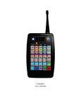
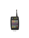
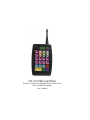
CM-T10-PRO and PRO-E
Wireless Control for ColorMaker Series LED Fixtures
with ColorRoll Technology
User’s Manual
Introduction
CM-T10-PRO and CM-T10-PRO-E (Enhanced)
This manual covers both the CM-T10-PRO and The CM-T10-PRO-E Remote. If your remote is the Enhance
version you will need to read the instruction for both models. The instruction for the enhanced version only
covers new features. This manual is written to take you through each step required to complete a procedure it
is recommend you follow each step in the sequence it is taught. There is a quick reference page to common
question once you have finished covering all the key features. There is also a phone number and email
address at the bottom of each page in case you need assistance. We have tried to keep the instructions as
simple as possible to ease the learning curve.
CM-T10-PRO-E is an enhanced version of the CM-T10-PRO transmitter. This enhanced version is
compatible with all Color Maker series LED fixtures including our ColorRoll technology. All the functions
found in the CM-T10-PRO work the same in the Enhanced version. We have added a few key features for
added control and to expand the number of fixture that can be controlled from a single handheld.
Comparison chart
Features
Addressable fixtures
Programmable Network Addresses
Programmable Scenes
Programmable ColorRolls
CM-T10-PRO
10
0
10
3
www.ColorMaker.net (407) 862-3363
CM-T10-PRO-Enhanced
90
9
90
27
Table of Contents
Fixture Select buttons -----------------------------------------------------------------------------------Scene Select buttons -------------------------------------------------------------------------------------Recording a Scene ---------------------------------------------------------------------------------------Play a Scene ----------------------------------------------------------------------------------------------Lesson :Record and Play a Scene ----------------------------------------------------------------------Scene Cross Fade and Dimmer Speed ----------------------------------------------------------------Functions: Beep, Shift Q10, Shift UP ----------------------------------------------------------------What is ColorRoll ---------------------------------------------------------------------------------------Creating a ColorRoll ------------------------------------------------------------------------------------Lesson: Create a ColorRoll with 10 Colors ----------------------------------------------------------Lesson: Create a ColorRoll with 3 Colors ------------------------------------------------------------Removing a dead spot from a ColorRoll Pattern ----------------------------------------------------Controlling a ColorRoll Fade ---------------------------------------------------------------------------Lesson: Adjusting ColorRoll Fade Rate --------------------------------------------------------------ColorRoll with Flash ------------------------------------------------------------------------------------ColorRoll Option on the DCR series Fixtures -------------------------------------------------------How Do I stop a ColorRoll in progress ---------------------------------------------------------------CM-T10-PRO Keypad reference table ----------------------------------------------------------------CM-T10-PRO-Enhanced Instruction -------------------------------------------------------------------
1
1
1
2
2
3
4
5
5
5
5
6
6
7
7
8
8
9
10
Why use Networking ? ----------------------------------------------------------------------------------Resetting Network Addresses (default) ----------------------------------------------------------------Fixture Address Vs Fixture Network Address --------------------------------------------------------Network Address in detail -------------------------------------------------------------------------------Network Programming Display ------------------------------------------------------------------------Network address with Fixtures -------------------------------------------------------------------------
10
10
10
11
11
12
Fixture Switch #8 ----------------------------------------------------------------------------------------Reset Network address in Fixtures ---------------------------------------------------------------------Programming the Remote with Network Addresses -------------------------------------------------Controlling fixtures using Network Addresses -------------------------------------------------------90 Fixture Buffer ( Memory) ---------------------------------------------------------------------------Function with Networking ------------------------------------------------------------------------------Fixture editing with Networking -----------------------------------------------------------------------Blackout ---------------------------------------------------------------------------------------------------Clearing Buffer -------------------------------------------------------------------------------------------Scene Control with Networking ------------------------------------------------------------------------New ColorRoll Features (enhanced version only) ---------------------------------------------------Programming ColorRoll using a Single Fixture ------------------------------------------------------CM-T10-PRO-E Keypad reference table -------------------------------------------------------------Binary conversion Table ---------------------------------------------------------------------------------FirmWare Updates ----------------------------------------------------------------------------------------
12
12
13
13
13
14
14
14
14
15
16
17
18
20
21
CM-T10-PRO
Fixture Select, Scene Record
CM-T10-PRO Keypad
The CM-T10-PRO has 24 keys some of which have multiple functions. These special functions are accessed
by pressing the Shift Key first followed by the function key. For example the ColorRoll buttons 1 through 3
also function as Crossfade, Speed and Beep. To access these functions the Shift
key must be pressed and held while the function key is pressed.
Fixture select Buttons
Fixture select buttons are marked Q1 through Q10 and have a purple back
ground color. By pressing and releasing one of these Q buttons it sets the
transmitter to communicate with the selected fixture. Q1 is for fixtures set to
address 1 and Q2 is for fixtures set to address 2 ect..... There is an address
conversion chart in the back of this manual to assist in setting the address for
the fixtures. Once a Q button (fixture) has been selected then the fixture can be
adjusted to any color mix by pressing the UP and DN keys on the corresponding colors RGB (red, green and blue). Each time a new Q button (fixture) is
selected the RGB value of the last fixture that was adjusted is saved in memory
so when you return to make further adjustments the transmitter know the last
RGB settings.
Example:
Press Q1, the display will read F 1 identifying fixture 1 has been selected. Press the UP key with the RED
back ground and fixture 1 will start lighting the red LED’s. The display will also read the amount of intensity
of the red LED’s in percent. This value is from 0 to 100. Do the same for green and blue.
Scene Select Buttons
Q1 through Q10 keys are also used to select scenes for record and playback.
A “scene” is the RGB (red, green and blue) settings for all 10 fixtures.
Recording a Scene
Once you have created a scene it can be saved to 1 of the 10 scene buttons (Q1-Q10). Press and release the
REC button in the Yellow Scene Control box. The display will read REC identifying that you are in record
mode. Now press 1 of the Q buttons, this will save the current scene to the selected Q buttons. After one
of the Q buttons has been pressed the scene is saved and the remote will return to normal mode ready for a
command. Scene are stored in memory and will not be affected by turning off the remote or changing the
batteries. The scenes will not be lost unless a new scene is recorded over a previously recorded scene.
Clear Button in the lower right side of keypad can be pressed to cancel the Record function and
return the transmitter to normal mode ready for a command.
Digital Readout
The digital readout displays the information of the selected fixture and the status of current settings. The
display will automatically shut down and display a “-” after two minutes of non use to conserve battery
power.
www.ColorMaker.net | [email protected] | (407) 862-3363
1
CM-T10-PRO
Scene Play
Play a Scene
“Play” means to send a recorded scene to the fixtures.
To play a previously recorded scene Press and release the Play key in the yellow Scene Control box. The
display will read PLY identifying that the remote is in Play mode. Now press 1 of the scene buttons (Q1Q10). If a scene was previously recorded then it will start to fade from the current RGB levels to the levels
that were saved. When a scene is played it will change all fixtures with the new RGB dimmer values.. The
display will read “FAd” (which is short for Fade) until the fixtures have all changed to the selected scene.
While FAd is displayed the remote will not accept any command. Once the fixtures have finished the
transition to the selected scene the remote will beep and the display will read “P” followed by the selected
scene. P is short for program or scene. P 1 means program (scene) 1 is currently displayed. We use P since S
looks like a 5 and we did not what to confuse you.
Lets do quick review and program a scene and play it back.
We will create a scene using 3 fixtures. If you don’t have three you can still follow.
1) With the remote ready for a command press and release Q1 the display will read “F 1”
2) Press the UP button with a red background until the display reads 100. Fixture 1 should now be bright red.
3) Press and release Q2. The display will read “F 2”
4) Press the UP button with a green back ground until it reads 100. Fixture 2 should now be green.
5) Press and release Q3. The display will read “F 3”
6) Press the UP button with a blue back ground until it reads 100. Fixture 3 should now be blue.
Hurray You have just created a scene with red, green and blue fixtures !
Now lets save the scene to Q1
7) Press and release the REC button in the Yellow Scene Control box. The display will read “REC”
8) Press Q1 to save the scene.
The scene has been saved to Q1 and the display will read the last fixture that was edited in this case that was
“F 3”
Now lets play back the recorded scene.
9) Press the Blackout button to turn off all fixtures. Wow a new key ! Blackout means just as it sounds, it
turns all fixtures off. It also erases the buffer.
Buffer is memory space where the RGB levels are stored while you make changes to each of the 10
fixtures. This is how the remote know each fixture setting when jumping from one Q to another.
Now that you have a empty buffer and all the fixtures are off. We can send a scene to the fixtures.
10) Press and release the Play button in the yellow Scene Control box. The display will read PLY identifying
you are in play mode.
11) Press the Q1 button and the display will read “FAd” (Short for Fade) and the 3 fixtures will start to fade
up. Once the fixtures have faded to the red, green and blue you will hear a beep and the display will read the
current scene which is P 1.
Continue to Next Page
www.ColorMaker.net | [email protected] | (407) 862-3363
2
CM-T10-PRO
Fade Rate, Dimmer Speed
Try one on your own and get a good feel on the procedure. Next we will get into how to control the Cross
Fade Rate and Dimmer Speed which are both associated with setting and playing back scenes.
What does Cross Fade Rate and Dimmer Speed mean ?
Cross Fade Rate is the time it takes to fade from one scene to the next.
Dimmer Speed is the how fast the dimmer value changes while pressing the red, green and blue UP and
DN keys.
Cross Fade and Dimmer Speed are Functions that can be changed in the remote. Due to the limited number of keys
these two functions share keys with ColorRoll 1 and ColorRoll 2.
When instructed keep the Shift key pressed until instruction are given to release.
Cross Fade
To access the function Cross Fade press and hold the Shift key then press and release the Cross Fade button. The
display will read the current setting Hi, Lo or OFF.
This is how it works:
The first press and release of the Cross Fade button will display the current setting. Sequential presses will change
the setting. The shift key must be held down during this procedure. Once the shift key is released the function is
terminated and the setting displayed is then saved. This function can be accessed again starting with the press of the
shift key.
What do they mean ?
Hi - when set to high the fade time is at its maximum. The fade from one scene to the next fades at a fast rate.
Lo- (short for LOW) when set to low the fade rate is set to it minimum. The fade from scene to the next scene fade at
a slower rate
OFF - when set to off there is no fade time the scene changes instantly.
Give it a try, Set the Cross Fade to Hi then play a scene and time how long the “FAd” is displayed or until you hear
the beep. Then set the Cross Fade to Lo and time it again. You will find that the time from off to full on takes roughly
15 seconds to where Hi is timed at roughly 5 seconds.
Cross Fade time is proportional to RGB values of each scene. Which means if a cross fade from 0 to 100 takes 15
seconds then a cross fade from 0 to 50 will take only 7,5 seconds. This is a factor for all 10 fixtures.
Dimmer Speed
To access the function Dimmer Speed press and hold the Shift key then press and release the Speed button. The
display will read the current setting Hi or Lo
This is how it works:
The first press and release of the Speed button will display the current setting. Sequential presses will change
the setting. The shift key must be held down during this procedure. Once the shift key is released the function is
terminated and the setting displayed is then saved. This function can be accessed again starting with the press of the
shift key.
What do they mean ?
Hi - when set to high the Dimmer levels changes fast
Lo- (short for LOW) the Dimmer levels changes slower
Give it a try, you can watch the display and see how fast it changes from 0 to 100 on each of the settings
www.ColorMaker.net | [email protected] | (407) 862-3363
3
CM-T10-PRO
Functions: Beep, All, Shift UP
MORE Functions...............
Here are three more functions that will use the Shift key. Remember to press and hold the shift key while selecting
these functions.
Beep-Beep
Some like it ON, some like it OFF.
This feature can be turned off and on. To change press and hold the Shift key then press Beep button which shares a
key with ColorRoll 3. There is no beep feedback or display when changing. If you hear the beep its ON if you don’t
its OFF.
Shift + Q10 Feature
The CM-T10-PRO has a special feature which allows you to select all fixtures regardless of the fixture address by
press and holding the Shift key then pressing Q10 also marked ALL. This sets the CM-T10-PRO to communicate
with all 10 fixtures with addresses from 1 to 10. The display will indicate ALL when this feature has been activated.
All 10 fixtures will respond to any commands transmitted including RGB levels and ColorRoll 1,2 and 3. By releasing
the shift key and pressing any one of the Q1 through Q10 will disable the ALL feature and the CM-T10-PRO will
return to single fixture operation.
Shift + UP Feature
This feature displays the dimmer value of the current fixture without changing the value. This function works on all
three UP buttons with the red, green and blue back ground.
Try it. Press and release Q1 to select a fixture. Press the RED up key to display a value. Now press and hold the
Shift key and press the RED UP buttons. It will display the dimmer value without changing it. Cool !
Lets review what we have learned
You learned to Create, Record and Playback Scenes with adjustable Cross Fade.
You learned how to change Cross Fade Times, Dimmer Speeds, Controlling all fixtures with one button and lets not
forget Beep-Beep.
Your now ready for advanced training, stay focused its really not a difficult feature to master.
Continue to Next Page
www.ColorMaker.net | [email protected] | (407) 862-3363
4
CM-T10-PRO
ColorRoll Technology
Introducing
ColorRoll™ Technology by JM Electronics Inc.
What is ColorRoll ?
ColorRoll is a technology developed by JM Electronics inc to operate on the ColorMaker line of wireless LED
fixtures. When activated a collection of colors are transmitted to the fixture by a remote. Once the fixture receives the
packet of data which takes less that 1 second the fixture will start rolling through the colors fading from one color to
the next with flicker free transition. This is an endless loop when the last color is reached the process starts over to
the first color. Once the ColorRoll has started the Fade Time from color to color can be controlled from 15 seconds to
5 minutes for each color. The fixture will operate completely independent of the transmitter until it receives a signal
to terminate. Custom colors are programmed and saved in the remote. There are 3 buttons marked ColorRoll 1,
ColorRoll 2 and ColorRoll 3 witch are used for the ColorRoll feature.
How many Colors are there?
If we do the math there are 16 million colors. There are 255 levels for each color with 3 Colors. Which totals 255 X
255 X 255 = 16,000,000
Where do I get the colors for a ColorRoll ?
Creating a ColorRoll is the same as creating a scene with a few minor adjustments. When a scene is created using all
10 fixtures Q1 through Q10 this represents the 10 colors in a ColorRoll. The color setting for Q1 will be the first color
in the ColorRoll and Q10 will be the last color in the ColorRoll. If you don’t have 10 fixtures then you can use the
digital display to set the RGB values. The remote does not know if you are using fixtures.
Remember to set dip switch #7 to the ON position on the fixture to activate the ColorRoll option (DCR-54)
How to create a ColorRoll using 10 colors
1) The first step is to chose the first color in the ColorRoll by selecting Q1 and then set the color. Do this through Q10.
2) With all 10 colors set press and release the REC key in the yellow Scene Control box. The display will read REC.
3) Now select where you want to store the ColorRoll pattern. Your options are ColorRoll 1, ColorRoll 2 or ColorRoll
3.
4) once you have made your selection the display will return to the last selected fixture and the ColorRoll has been
saved.
And you thought is was going to be difficult! Well were not done yet.
Lets do a ColorRoll with only 3 colors, Red, Green and Blue.
1) The first step is to chose the first color in the ColorRoll by selecting Q1 and then set the color. Do this through Q3
since we only want 3 colors.
This is the confusing part so stay focused.
The ColorRoll knows you have 3 colors Red, Green and Blue. But it does not know whether you intended the 4th
color which if OFF to be part of the ColorRoll pattern. Well its been programmed to assume Yes its part of the pattern.
So now your ColorRoll looks like Red, Green, Blue and OFF. So if you played this ColorRoll pattern back it will
look like a dead spot in your program.
Stay Focused …
www.ColorMaker.net | [email protected] | (407) 862-3363
5
CM-T10-PRO
ColorRoll, ColorRoll Rate
How do I remove the dead spot in my ColorRoll ?
We need to tell the remote that the 4th color which is OFF is not part of the pattern. The way we do this is to make the
colors not in the pattern the same as the last color in the pattern. The last color in the pattern is Blue so we would set
Q4 to blue, Q5 to blue, Q6 through Q10 to Blue. Now when the ColorRoll runs it will see Red, Green then Blue when
it gets to the 4th color its still blue so it checks colors 5,6,7,8,9 and 10. Until a new color is used the ColorRoll will
not change so our results will be Red, Green and Blue then repeats.
Example 1: ColorRoll setting that starts with Red then fades through all 10 colors then repeats.
Q1
Q2
Q3
Q4
Q5
Q6
Q7
Q8
Q9 Q10
Example 2: ColorRoll process that starts with Red the fades to Green then fades to Blue then repeats.
Q1
Q2
Q3
Q4
Q5
Q6
Q7
Q8
Q9 Q10
If you can master the ColorRoll programming then its all down hill from here.
Starting a ColorRoll
Starting a ColorRoll is done a little different that starting a scene. With ColorRoll the Play button is not use just select
a fixture Q1 through Q10 then select a ColorRoll pattern ColorRoll button 1, 2 or 3. If a ColorRoll program was
recorded then it will start. Select another fixture and then another ColorRoll or use the same ColorRoll. Shift + Q10
works well with ColorRoll to send a Patterns to all fixtures with one button.
Since the ColorRoll is running independent of the remote some fixtures may roll slightly faster which after time
will cause them to roll unevenly. Choose from one of our other ColorMaker line of transmitters with continuous
signal control if tracking is needed.
Controlling the ColorRoll
The ColorRoll patterns can be controlled on how fast the colors fade and weather they fade or Flash. Fade rates can be
set from 3 seconds to 5 minutes.
*Remember fade rates are proportional to dimmer values
ColorRoll fade rate keys are shared with the Red and Green UP and Down keys. Marked with Roll Rate. Rate keys are
only active after a ColorRoll patterns has been sent to the fixture.
ColorRoll Fade Rate setting
There are two fade rate settings. Rate and Rate Multiplier. Fade rate keys are shared with the Red and Green UP and
Down keys. Marked with Roll Rate. Rate keys are only active after a ColorRoll patterns has been sent to the fixture.
These two values are controlled by Red and Green UP and DN keys. The Red UP and DN keys controls the Rate
Value the Green UP and DN keys controls the Rate Value Multiplier.
Continues to next Page
www.ColorMaker.net | [email protected] | (407) 862-3363
6
CM-T10-PRO
ColorRoll Fade Rate, ColorRoll Flash
Adjusting the ColorRoll Fade Rate
Example:
1) Start a ColorRoll by selecting a fixture, Q1 will be fine.
2) Press a ColorRoll button which has been previously programmed.
3) After pressing a ColorRoll button the Red and Green UP and DN dimmer keys become Rate Keys.
4) Press the Red DN button and bring the Rate to 0 if not already indicated by the display. Do the same for Green.
The ColorRoll is now running at full speed roughly 3 seconds per color.
To increase the fade rate (make it fade slower) Press the Red UP key which will increase the fade. Bring it up to about
50%. There will be a noticeable decrease in the roll rate. By increasing Rate Value Multiplier which is the Green UP
and DN keys it will make the fade rate even slower. It probably will not be noticeable but over a period of 3 to 4 minutes you will notice a change.
Fade Rate Values Saved to Memory
Each of the ColorRoll buttons stores its own fade rate and fade rate multiplier values so fast and slow ColorRoll
patterns can be programmed. The rate values are saved each time they are changed. When a ColorRoll button is re
programmed the Fade Rate Value and the Fade Rate Multiplier Value of the previous ColorRoll will be used until it is
changed.
-FLASH Need a Disco Look ? ColorMaker can do it.
Along with Fade Rate there is also a control to make the LED fixture FLASH through the ColorRoll pattern. After
a ColorRoll button is pressed the Blue UP and DN keys become Flash Control buttons. By bringing the Value above
50% it turns off the fade control and colors flash through the ColorRoll patterns. The flash rate can be controlled by
Fade Rate and Fade Rate Multiplier. Flash value is also stored when changed.
www.ColorMaker.net | [email protected] | (407) 862-3363
7
CM-T10-PRO
ColorRoll Options
ColorRoll Option on the DCR series Fixtures
The ColorRoll option can be enabled of disabled using switch #7 on the back of the fixture. Turn switch #7 ON to enable ColorRoll and turn switch #7 OFF to disable ColorRoll.
Why Disable ColorRoll ?
Some events you might not want to use all fixtures with the ColorRoll feature enabled. When the ColorRoll feature is
disabled on a few fixtures it give you more fallibility and if done right an added control over your event.
Example:
Two fixtures set to the same address let use Q1. The network address is also the same for both fixtures.
1) On one fixture you will enable the ColorRoll feature and the other you will disable the ColorRoll.
2) With both fixtures ready press Q1 on the remote and press ColorRoll 1. Notice that only the fixture with switch # 7
to the ON position is rolling through the colors.
3) Now press Q1 on the remote and adjust the RGB dimmer levels. The fixture without the ColorRoll switch #7 is
controlled while the other fixture continues with the ColorRoll.
Now you have two fixtures under your control with a single address.
How do I Stop a ColorRoll in Progress ?
There are two options to stop a ColorRoll.
Option 1: Press the blackout button
Option 2: Select the fixture that is currently rolling a ColorRoll pattern and bring dimmer levels of the RGB to 0.
During a ColorRoll the fixture is still receiving data from the remote. When it detects that the dimmer levels have all
reached 0 then is stops the ColorRoll pattern and returns to normal operating mode.
What are the advantages of using option 1 or 2 ?
Option 1: Blackout affects all fixtures in the event. Total blackout !
Option 2: Lets you stop a ColorRoll on a single fixture without affecting the other 9 fixtures in your event.
www.ColorMaker.net | [email protected] | (407) 862-3363
8
CM-T10-PRO
Quick Reference Table CM-T10-PRO
Reference Table for CM-T10-PRO Key Controls
Button
Shift Function
No Function
Function
Fixture select buttons also used to select scenes during record and playback
Cross fade selector
HI, Low or Off
ColorRoll select 1
Dimmer Speed
HI or Low
ColorRoll select 2
Key press beep
On or Off
ColorRoll select 3
No Function
Sets all Fixture Dimmer levels to 0
No Function
No Function
No Function
Clears previous function
Selects All fixtures for editing Fixture select 10
No Function
Record and Play buttons for Scene and ColorRoll features
No Function
Dimmer control for Red
When fixture is in ColorRoll sets the roll rate value
No Function
Dimmer control for Green
When fixture is in ColorRoll sets the roll rate multiplier value
No Function
Dimmer control for Blue
When fixture is in ColorRoll sets the Fixture to Fade or Flash
www.ColorMaker.net | [email protected] | (407) 862-3363
9
CM-T10-PRO-E
Features, Network Addressing
Instruction for CM-T10-PRO-E (Enhanced)
This portion of the manual only covers the new features found in the Enhanced version. If you are a new user of the
CM-T10-PRO remote please read instructions for the standard version. Version 206 or higher See Page 21
New Key Features
- 9 Programmable Network addresses
- Expanded memory for 90 programmable scenes and 27 ColorRoll patterns.
- Master Blackout of all 90 fixtures
- Master Play
- Master Record
Why use Network Addressing ?
There are Several ways to take advantage of network addresses.
1) By using multiple network addresses you can expand your event to use up to 90 separately addresses fixtures.
2) Using network addresses multiple transmitters can be used in the same location giving you the ability to use up to
1,270 separately addressed fixtures for your event.
3) With the growing popularity of the ColorMaker Series LED fixtures its possible to have multiple users in the same
location. Programming your remote with Network addresses secures your event so others users remotes will not
communicate with your fixtures unless they use the same network address.
How do I use a Network Address ?
To use a network address you will need to choose an address setting. Addresses range from 1 to 127. After you have
programed the remote you will need to set the fixture with the same network address in order to communicate with
fixture. There are 9 programmable network addresses. Q1 through Q9 also share with N1 through N9 found in the
upper left corner of the Q buttons. All 9 Network buttons are set to default from factory. The default network address
will communicate with the DCR line of LED fixture without making changes. If you find you are unable to get your
own network address to work you can always reset back to the default address.
Resetting Network Address to default factory settings
With the remote turned OFF press and hold the Clear key located in the lower right corner of the keypad. While
holding the clear key down turn on the remote. You will hear a Beep-Beep then the display will read “---” This resets
only Net 1 (Q1) to factory default.
What do I need to know before I try to program my own Network address ?
Programming a network address is a simple process if you know how to match the network address to match the
network address in the fixture, Until you get familiar with the programming procedures its helpful to have a fixture in
front of you while programming. We will reference using a DCR-54 fixture.
Lets first look as the back of the DCR-54 fixture. There are 8 dip switches that are used to program the network address.
*Don’t get confused the Fixture Address is not the same as the fixture Network address.
Lets talk about the difference between the Fixture Address and the Network Address
Fixture Address is the address that will identify which Q button will communicate with the fixture. There are 32
option on the fixture which will use switches 1 through 6.
NOTE: The CM-T10-PRO and PRO-E only use 10 which are (Q1-Q10) so you will only use switches 1 through 4
when programming fixture when using CM-T10-PRO and PRO-E
Continue to Next Page
www.ColorMaker.net | [email protected] | (407) 862-3363
10
CM-T10-PRO-E
Network Addressing, Network Display
The CM-T10-PRO and PRO-E use fixed addresses for each Q button and cannot be changed, Q1 is always address 1
and Q2 is always address 2 ect.....
There is a Binary conversion chart in the back of the manual to assist in your setting the fixture address to match the
desired Q button on the remote.
If you are still a little confused about the address setting don’t worry we will take you through the process in just a
few pages.
Lets get into the Network address (only available on the CM-T10-PRO-E (Enhanced)) To explain in non technical
way lets use an apartment building. There are 9 buildings in ColorMaker Village and each building has 10 apartments.
All the apartment have a number on the front door 1 through 10 so the pizza man know where to deliver the pie. But
when he arrive there are nine building in ColorMaker Village that all have an apartment with the #1 on the front door.
So now he need to know which of the nine building he need to get to before the pie gets cold. He check the address
again and notices Building 2 Apartment 9. Well that’s Networking. If you wanted to turn on the light you would
select Net 2 and Q9.
Getting back to reality lets get the technical theory of the network address.
Network address uses switches 1 through 7 on the DCR-54 for a total of 127 different network addresses to choose
from when programming. The same setting you use on the fixture will need to be programmed in the remote.
Lets see how
With the remote turned OFF press and hold down the Shift key and turn the remote ON. The display will read SEL
identifying you are in Network program mode. This is where you will select which Network address you want to program your choices are N1 through N9 found on Q1 through Q9. In the case we will use N1. Press and release N1 key
and the display will now read 1-1.
What does 1-1 mean ?
The first number is the switch number in this case 1.
The second number is the switch position. 1 means ON and 0 Means OFF in this case the switch is ON. There are 6
more switches we need to check. Press the Red UP key to advance to the next switch. You should get 2-0 which means
switch #2 is set to the OFF position. Continue to press the Red UP button to check all 7 switch positions. Use the Red
DN button to count back to the first switch which will read 1-1.
This is where you go AHHHH
This is the display you should have seen if the remotes network address N1 was set to default. The table below
lists the switch number and the switch position for the displays numbers.
Display reads
Identifies Switch Number
Identifies Switch Position
1-1
1
ON
2-0
2
OFF
3-1
3
ON
4-0
4
OFF
5-1
5
ON
6-0
6
OFF
7-1
7
ON
Continue to Next Page
www.ColorMaker.net | [email protected] | (407) 862-3363
11
CM-T10-PRO-E
Network Addresses with Fixtures
Now lets compare the table to how we set the Network address on the fixture.
The table has two columns that list the switch number and the switch position. We will use the same setting at the
table to set the switches 1 through 7 on the fixture.
With the fixture unplugged from the power supply use a small screw driver or paper clip and change the switches to
the positions to match the table. Be gentle with the switches...... Switch 8 will not be used at this time so it will remain
OFF
Your switch should look like this.
12345678
Why did we not use Switch # 8 ?
Switch # 8 is used to set the network address. Since the 8 witches are use to set the Fixture Address and the Fixtures
Network Address we need to let the fixture know which address we are programming.
Lets Program the network address.
1) With the fixture unplugged from power switch the # 8 switch to the ON position. This tell the fixture we want to
program the network address.
2) Now plug in the fixture to power supply (battery or wall plug) Use only ColorMaker power supplies.
3) Wait 3 seconds then unplug the supply and turn OFF switch # 8. The network address is now programmed. Your not
done yet.
4) Now you need to set the fixtures address. In this case we will use address 1 so it will operate on Q1. Turn Switch 1
ON and 2,3,4,5 and 6 OFF. This identifies address #1.
Remember the DCR-54 fixture uses switches 1 through 6 so they all need to be set properly even though the
CM-T10-PRO and PRO-E only use switches 1 through 4.
5) The last step is to TEST. Always TEST its the most important procedure to make sure your remotes and fixtures do
what you have intended them to do before an event. Turn OFF the remote to reset. Wait 2 seconds and turn it on. Do
not press any buttons when turning on the remote.
Press Q1 and raise the dimmer levels. If it worked then programming was successful. If not then there was an error in
programming follow these steps to reset the address to default.
Resting the remote and Fixture to the Default network address.
If you are unable to get a network address programmed properly you can reset both the remote and fixture back to
default address.
Reset the Remote
With the remote turned off. Press and hold the Clear key located in the lower right side of the keypad. Turn on the Remote and you should hear a Beep-Beep indicating the default network address has been programmed. Note: This reset
only N1, N2 through N9 remain unchanged.
Reset the Fixture (DCR-54)
With the fixture unplugged from power turn switches 1 though 7 to the OFF position. Turn switch 8 to the ON position. Plug in power supply wait 2 seconds then unplug from power. Turn switch 8 to the OFF position and turn on
switch 1. Switch 1 should be the only switch in the ON position. Plug in the power supply and press Q1 on the remote
and test. If you are unable to get the communications please call or email for assistance.
www.ColorMaker.net | (407) 862-3363
12
CM-T10-PRO-E
Programming Network Addresses
How Do I program My remote with a new Network Address ?
You have learned how to match the remotes network address to the fixtures network address. Now lets program a new
network address to the remote. Until you get familiar with this procedure we recommend you not change N1. Keep
this network address to default. For this example we will use N2.
Network Programming Steps:
1) With the remote turned off press and hold down the shift key while turning on the remote. The display will read
SEL identifying you are in network program mode.
2) Select N2 identifying we want to program network address #2. The display will read switch 1 and the position of
the switch 1 or 0
3) You have already learned how to scroll through the switches 1 through 7 using the Red UP and Red DN keys. Now
we want to change the switch position.
4) With the display reading the first switch use the Blue UP key to turn the switch position ON and the Blue DN key
to turn the switch to the OFF position. After you have set the position use the Red UP keys to advance to switch 2 and
make the adjustments. You can go back for forward through all seven switches the remote will remember each time
you make a change.
5) After you have made all the changes press the REC key in the yellow Scene Control box. The network address is
now saved and the remote will ready for a command. Be sure to change the fixture you want to use on this network
address. Follow this procedure for network address N3 through N9 if needed.
Write down the network address setting and it would also be suggested to apply the network address to the outside of
the fixture for reference.
Don’t use network address 0000000 or 1111111 as these are use for other functions we will discuss later in this
manual.
Controlling the fixtures using network addresses.
Now that you have programmed the remote and fixtures with new network addresses lets go through the procedure
on how to control them. When the remote is turned on the N1 is selected by default. To select another network address press and hold down the Shift key and press 1 of the 9 network keys N1 through N9. These keys are shared with
the Q1 through Q9. After you have made a selection the display will read “n” and the selected network number. The
remote automatically switched to the network address that was programmed and is ready for a command. Now select
a fixture and make any adjustments.
Remember the shift key when pressed toggles the (Q) fixture buttons to (N) Network buttons.
90 Fixture Memory Buffer
The CM-T10-PRO-E can control up to 90 separately addressed fixtures when using 9 different network addresses.
Each of the 9 network buttons has its own memory (buffer) to store changes made to the 10 fixtures within each network.
What does that mean ?
It means you can jump from one network address to another without loosing the RGB values of each of the 10 fixtures
so when you return for further adjustments it goes back to here you let off. This enables you to create a scene with 90
fixtures. What an event that would be!
www.ColorMaker.net | [email protected] | (407) 862-3363
13
CM-T10-PRO-E
Editing Fixtures, Blackout, Buffer
Do all Functions work with Network addresses ?
Yes, Scenes, ColorRolls, Blackout, Shift + Q10 (All Select) , Record and Play all work with network buttons. However some work a little differently if you have been using the non enhance version of the remote. We will cover this in
detail as we go.
Editing Fixtures
Lets start with the basics and use two network addresses using two fixtures. You will need to program N2 with a network address and set a fixture to match for this example to work. Set both fixtures to address 1 so you will have one
fixture with network N1 set to address 1 and a fixture with N2 set to address 1.
1) Turn on the remote and select Q1, N1 is selected by default. Adjust the fixture to 100% red for testing.
2) Press and hold the shift key and press N2. The display will read N-2 identifying you are now using network address
2.
3) Release the shift key and press Q1 to selected fixture 1 and set the color to 100% blue. Now you should have two
fixtures one red and one blue.
4) Now lets go back to N1. Press and hold the shift key and press N1. Release the shift key and press Q1. Now press
the Blue UP key. Notice that the fixture remembers that you already made changes to the red and you are now adding
blue. This process works the same way with all 9 network addresses.
Now you think “Wow I need more fixtures” so just give us a call
Blackout Fixtures
The Blackout button works the same way as it did on the non enhanced version but we added a feature we call Master
Blackout. When the blackout button is pressed it will turn off all fixtures that are on the network address you currently
have selected. However it will not blackout the other fixtures on the other 8 network addresses.
What is the difference between Blackout and Clearing (erase) Buffer ?
The blackout button on the non enhance version did two things. It turned off all the fixtures and erased the buffer. This
works the same way on the enhanced version. However when you use the Master Blackout the fixtures turn off but the
buffer is not erased.
What does that mean ?
It means the buffer still contains that last RGB settings of all 90 fixtures so when you go back to edit the fixtures will
jump from blackout to the last RGB values.
How do I clear the buffer after a Master Blackout ?
Press and hold the shift key and press Clear button located in the lower right side of the keypad. This will clear the
buffer for all 90 fixtures.
www.ColorMaker.net | [email protected] | (407) 862-3363
14
CM-T10-PRO-E
Scene Control with Networking
Scene Control Using Network Addresses
Recording and Playing scenes work the same way as on the non enhanced version with one exception, You get 90
programmable scene buttons instead of 10. Each of the 9 network buttons store 10 scenes with each scene using all 10
fixtures.
When a scene is activated only the fixtures on the current network address are activated. This is also true during recording only the fixtures on the current network address will be recorded.
How do I play scenes that use multiple network addresses ?
When your scene includes several network addresses then each needs to be played separately. This can be done easily
and have some nice effects. Lets assume you want to play scene 1 on network address 1 and scene 3 on network address 2.
1) Press shift and N1 to access network 1
2) Press Play then scene 1. If your scene is in fade mode then you will need to wait until the display reads P-1 indicating that the current scene has finished.
3) Press Shift and N2 to access network 2
4) Press play then scene 3. Now both scene 1 on network 1 and scene 3 on network 2 is displayed in your event.
Once you get the familiar with this procedure then you will be able to run several scenes with multiple network addresses without delays.
This procedure can be used for all 9 network addresses.
Recording scenes with multiple network addresses works the same except you use the record button.
1) Press shift and N1 to access network 1
2) Set up a scene using fixtures that are addressed to network 1
3) Press record then press 1 of the scene buttons where you want to store the scene.
4) Press Shift and N2 to access network 2
5) Set up a scene using fixtures that are addressed to network 2
6) Press record then press 1 of the scene buttons where you want to store the scene.
This procedure can be used for all 9 network addresses.
www.ColorMaker.net | [email protected] | (407) 862-3363
15
CM-T10-PRO-E
New ColorRoll Features
New ColorRolll features found in the CM-T10-PRO-E
The ColorRoll feature works the same way as on the non enhanced version and we have added a few features including 27 ColorRoll pattern and included a feature which allow the user to program ColorRoll patterns using a single
fixture.
If you are a new user to the CM-T10-PRO or PRO-E then you should review procedures for ColorRoll in the non
enhanced instruction found in the front of this manual.
Here is a quick review
ColorRoll patterns are played directly without the need to use the Play button. Just select a fixture then select one of
the ColorRoll buttons. There are three to choose from. After a ColorRoll button has been selected then the Red and
Blue UP/DN dimmer buttons become Fade Rate buttons to adjust the ColorRoll fade time.
Remember to set dip switch #7 to the ON position on the fixture to activate the ColorRoll option (DCR-54)
Using ColorRoll feature with Multiple Network addresses.
ColorRoll feature now include 27 ColorRoll pattern buttons that can be recorded with custom colors. Each of the
9 network addresses can store 3 patterns. Each time a new network button is pressed then a new set of patterns are
loaded.
Need more than 3 ColorRoll patterns for a single network address ?
We have developed the CM-T10-PRO-E to be very flexible for the user to custom program the remote to meet specific
need for an event. One of these is the ability to program custom network addresses as you have already learned. One
feature we want to cover is using multiple network buttons with the same network address.
Lets say you want to have 6 ColorRoll buttons for your event but you only want to use one network address so when
you make scene changes you don’t need to change your network address to complete the scene. Well it can be done by
programming two network buttons with the same network address.
This will only work on ColorRoll feature when using multiple network with the same network addresses with scene
playback you may not get the response you intended.
This is how it works
1) Program network buttons 1 and 2 with the same address.
2) Now program 3 different ColorRoll and save them to ColorRoll buttons 1, 2 and 3 using network address 1.
3) Switch to network 2 and program 3 more ColorRoll patterns and save them to ColorRoll buttons 1,2 and 3.
Now you have 6 ColorRoll patterns programmed to one network address.
4) Now you can play them back. Use network 1 to use ColorRoll 1, 2 and 3 and use network 2 to use ColorRoll 4, 5
and 6.
This procedure will work on all 9 network buttons for a total of 27 ColorRoll patterns for a single network address.
www.ColorMaker.net | [email protected] | (407) 862-3363
16
CM-T10-PRO-E
ColorRoll Programming
Programming a ColorRoll using a single fixture.
There is a new way to Program ColorRoll Patterns found only in the CM-T10-PRO-E. In the non enhanced version
you needed 10 fixtures set to addresses 1 through 10 to see the colors or had to use the digital display on the remote to
calculate the colors.
By popular demand we have included this feature in the enhanced version of the CM-T10-PRO-E. The old way still
works. You will need 1 fixture set to address 1 and set the network address to match the network button on the remote
that you are planning to use.
This is how it works.
1) With the remote turned OFF. Press and hold the ColorRoll 1 button while turning on the remote. This puts the remote into the new ColorRoll programming mode. Now each of the Q fixture select buttons will display the color you
are programming on fixture 1.
2) Select fixture 1 and set the colors.
3) Select fixture 2. Notice that fixture 1 turned OFF. This means there are no colors yet programmed in color 2 of your
ColorRoll pattern. Once you make changes they will be display again on fixture 1. Do this all the way though Q10.
You can press any one of the Q buttons to go back through the colors the fixture will automatically change to the color
you previously programed.
4) Once you have finished all the colors Press Record and the ColorRoll button you want to save the new pattern. You
can repeat the same process for the other 2 ColorRoll.
5) After you have finished programming the ColorRoll patterns press the Clear key in the lower right side of the
keypad to return the remote to normal operation. This can be repeated at my time as needed just follow this procedure
from step number 1.
www.ColorMaker.net | [email protected] | (407) 862-3363
17
CM-T10-PRO-E
Button
Quick Reference Table CM-T10-PRO-E
Shift Function
Network Select
Function
Fixture select buttons also used to select scenes during record and playback
Cross fade selector
HI, Low or Off
ColorRoll select 1
Dimmer Speed
HI or Low
ColorRoll select 2
Key press beep
On or Off
ColorRoll select 3
No Function
No Function
Clear Buffer
Clears previous function
Selects All fixtures for editing Fixture select 10
No Function
Record and Play buttons for Scene and ColorRoll features
Display Value
Dimmer control for Red
When fixture is in ColorRoll sets the roll rate value
Display Value
Dimmer control for Green
When fixture is in ColorRoll sets the roll rate multiplier value
Display Value
Dimmer control for Blue
When fixture is in ColorRoll sets the Fixture to Fade or Flash
www.ColorMaker.net | [email protected] | (407) 862-3363
18
CM-T10-PRO-E
Quick Reference Functions
Below is a list of functions and the process needed to access the functions.
These are the function available when key is pressed and the remote is turned on.
Power UP Functions
Key
Clear
Shift
ColorRoll 1
Function
Clear all 9 network address buffers
Sets remote to program network address
Sets remote to program ColorRoll using a single fixture
Functions used during operation of the remote. The shift key is pressed and held while function key is pressed
Keys
Shift + ColorRoll 1
Shift + ColorRoll 2
Shift + ColorRoll 3
Shift + Q10 (All)
Shift + Clear
Shift + Red UP
Shift + Blue UP
Shift + Green UP
Shift + N1 through N9
Fixture operating Functions
Function
Cross fade setting
Dimmer Speed
Beep Sound Enable/Disable
Select All fixtures command
Clears buffer for all 9 networks
View dimmer red value
View dimmer blue value
View dimmer green value
Network select
www.ColorMaker.net | [email protected] | (407) 862-3363
19
CM-T10-PRO-E
Binary Conversion Table
Use the table below to assist in setting up your fixtures to operate on a desired Q button on the remote. Table includes
address settings for up to 32 fixture addresses. The CM-T10-PRO and PRO-E only use the first 10.
Fixture
Q1 Button
1
2
3
4
5
6
7
8
9
10
11
12
13
14
15
16
17
18
19
20
21
22
23
24
25
26
27
28
29
30
31
32
Fixture Address Switch
1
2
3
4
5
6
7
Key Notation
8
Switch ON
Switch OFF
ColorRoll Option
NOT USED KEEP OFF
Switch #7
On the DCR series fixtures switch # 7 is used for ColorRoll. Turn
switch #7 to the ON position to enable ColorRoll or turn switch #7 to
the OFF position to disable ColorRoll.
Switch #8
On the DCR series fixture switch #8 is used to program network addresses. Switch #8 should always stay in the OFF position unless a
new network address is being programmed.
Example: We want to set fixture address to receive on Q5 with
ColorRoll feature enabled (on)
Switch # 1 ON
Switch # 2 OFF
Switch # 3 ON
Switch # 4 through 6 OFF
Switch # 7 ON
Switch # 8 OFF
www.ColorMaker.net | [email protected] | (407) 862-3363
20
CM-T10-PRO-E Firmware Updates 206-208
ColorMaker Inc. has made some enhancesments to the CM-T10-PRO-E hand held transmitter to make it more user
firendly. Since the release of the new PS series wireless LED fixtures with Auto Address features the user is no longer
required to mannualy set the 8 dip swtiches to set the address or try to convert the binary codes into usable addresses.
The Auto Address features does all the calculations for both the Network address and the Channel address.
Programming Network addresses
There are 90 possible network addresses available to the user. The CM-T10-PRO-E has 9 programmable network buttons to store the network addresses. Follow these simple steps to program one address.
Step 1) Trun the transmitters power swich to the OFF position.
Step 2) Press and hold the SHIFT key on the keypad while turning the power switch to the ON position. You should
get three dashes “---”. No release the SHIFT key and the display should read “SEL”. which means Select.
Step 3) Press one of the 9 “N” buttons marked in gray in the upper left corner of the Q buttons. This selects which
network button you are going to program or re-program.
Step 4) Once you have made your selection the display will read small “n” followed by a number between 1 and 90.
This number identifies what network address is currently stored for that network location.
Step 5) Use the RED UP and RED DN keys to change the value.
Step 6) Once you have made the changes press the “REC” button in the Scene Control box to save your changes. To
program another address just follow steps 1 through 6.
NEW V206 feature
Firmware version 206 also includes a network button ID. When the user changes network addresses the CM-T10PRO-E will display the actual network number the transmiter button was assigned. When a network number is displayed it is preceeded by the small “n”.
www.ColorMaker.net | [email protected] | (407) 862-3363
21
NOTES:
www.ColorMaker.net | [email protected] | (407) 862-3363
22
Warranty
ColorMaker hereby warrants, to the original purchaser, ColorMaker
products to be free of manufacturing defects in materials and
workmanship for a period of (90 days) from the date of purchase.
This warranty shall be valid only if product is purchased within
the United States of America. It is the owners responsibility to
establish the date and place of purchase by accepting evidence, at
the time service is sought.
For warranty service, send the product to the ColorMaker factory.
All shipping charges must be prepaid. Equipment must be sent in
its original package and to include all control devices.
Warrant is void if serial number has been altered or removed, seals
have been voided, if the product is modified in any manner which
ColorMaker concludes, after inspection, affects the reliability of
the product; if the product has been repaired or services by anyone
other than ColorMaker unless prior written authorization was
issued to purchaser.
ColorMaker reserves the right to make any changes in the designs
and/or improvements upon its products without any obligation to
include these changes in any products theretofore manufacture.
Factory location:
ColorMaker Inc
980 Sunshine Lane Suite T
Altamonte Florida 32714
(407) 862-3363