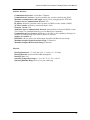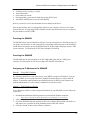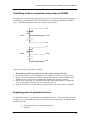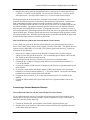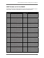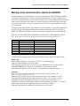
1
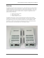
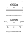
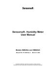
Sensorsoft Real-Time Contact and Voltage Sensor User Manual Models SS6420J and SS6420E Manual P/N 071-0108 Rev 9 December 11, 2015 Copyright © 2006-2015 Sensorsoft Corporation, All rights reserved. Sensorsoft is a trademark of Sensorsoft Corporation. Table of Contents Overview.......................................................................................................................................... 4 About this Manual............................................................................................................................ 5 SS6420J (v5.08) Specifications ...................................................................................................... 6 SS6420E (v5.08) Specifications...................................................................................................... 8 Installing the SS6420..................................................................................................................... 10 Choosing a location for installation ............................................................................................ 10 Connecting the SS6420J to a serial port ................................................................................... 10 Powering the SS6420J .............................................................................................................. 11 Powering the SS6420E.............................................................................................................. 11 Assigning an IP Address to the SS6420E ................................................................................. 11 Connecting and monitoring dry-contacts....................................................................................... 13 Internal circuit diagram of contact inputs ................................................................................... 13 Connecting and monitoring voltages ............................................................................................. 13 Internal circuit diagram of voltage inputs ................................................................................... 14 Controlling loads or equipments using relays on SS6420 ............................................................ 15 Supplying power to peripheral devices.......................................................................................... 15 Contact Input Application Examples.............................................................................................. 16 Connecting a Motion Detector ................................................................................................... 16 Connecting a Glass-break Detector .......................................................................................... 17 Connecting a Carbon Monoxide Detector ................................................................................. 18 Connecting a Smoke Detector................................................................................................... 19 Connecting a Door Contact ....................................................................................................... 20 Writing custom software for the SS6420 ....................................................................................... 22 Sensorsoft Device Monitoring .NET Component for Windows.................................................. 22 Simple Text Command Interface ............................................................................................... 22 SSDP Variable List for the SS6420............................................................................................... 23 Making serial communication cables for SS6420J........................................................................ 25 Getting Help................................................................................................................................... 28 Limited Warranty........................................................................................................................ 28 Technical Support ...................................................................................................................... 28 30 Day Money Back Guarantee................................................................................................. 28 Returns....................................................................................................................................... 28 Sensorsoft Real-Time Contact & Voltage Sensor User Manual Overview The SS6420 Sensorsoft Contact & Voltage Sensor is a multi-functional device with the ability to simultaneously monitor 12 (dry) contact points, 3 voltage sources, and control two relays. It is suitable for requirements where the customer needs to be informed immediately (< 0.5 second) upon the (Boolean) state change of a contact closure or voltage level. Applications for this product include the following: intrusion and security systems safety warning systems building management systems The SS6420 can also power a variety of safety and intrusion (12 VDC) detectors making installation easy and similar to that of intrusion alarm panels. The built-in single-pole-doublethrow (SPDT) relays can be used to control the ON/OFF state of small equipment or loads. The SS6420 is available with two different communication interfaces; The SS6420J with an RS232 serial interface and the SS6420E with a 10/100 Ethernet interface. 4 Sensorsoft Real-Time Contact & Voltage Sensor User Manual About this Manual The Sensorsoft Real-Time Contact & Voltage Sensor may also be referred to as the SS6420, a Sensorsoft device or SSD (Sensorsoft Soft Device) throughout this manual. 5 Sensorsoft Real-Time Contact & Voltage Sensor User Manual SS6420J (v5.08) Specifications Electronic: Total Number of Monitored Inputs: 15 (12 - contact inputs, ground referenced, numbered C1-C12) (3 - opto-isolated voltage inputs, not ground referenced, numbered V1-V3) Total Number of Controlled Outputs: 2 (2 - SPDT electromagnetic relay contacts (NO, NC, COM), numbered RL1 and RL2) Screw Terminal Connectors: 8 connectors x 6 polls/connector (48 poles total), 3.50 mm pluggable screw-down connector, AWG 16-24, Molex P/N 39351-0006. Relay contact load rating (RL1 or RL2): 1.5 Amp at 30 VDC Maximum relay contact operating voltage (RL1-RL2): 30 VDC Maximum relay contact operating current (RL1-RL2): 1.5 Amp Maximum relay contact switching capacity (RL1-RL2): 62.5 VA, 33 W Detection Method - Contact Inputs (C1-C12): Input transistor circuit detects external resistance between input and ground terminals. External resistances below 15K ohm produce a CLOSED condition/state. External resistances above 600K ohm produce an OPEN condition/state. Input Resistance of Opto-isolated Voltage Inputs (V1-V3): 16K Ohm Detection Method - Opto-isolated Voltage Inputs (V1-V3): Optical coupler detects voltage difference between V+ and V-. A voltage difference, on these terminals, below approximately 3 volts produces an OFF condition/state. A voltage difference, on these terminals, equal to or greater than approximately 3 volts produces an ON condition/state. The minimum recommended voltage input for an ON condition/state is dependent upon resistance of the voltage source. Minimum Detectable Input Duration: 60 mS. This specification is not valid during a write to any variable in the SS6420’s non-volatile memory. Maximum Time from State Change to Issue of Interrupt Packet: 300 mS. This specification is not valid during a write to any variable in the SS6420’s non-volatile memory. Maximum Applied Voltage on Opto-isolated Voltage Inputs (V1-V3): 30 V Power source: Port-powered (RTS and DTR, both asserted) or using an external AC-DC power adapter. To operate relay contacts, requires external power. Power supply current drain: < 20 mA External Power Source Connector: 2.1 mm jack External Power Source Requirements: 6 VDC, 20 mA capability, center positive (input circuit is polarity protected). Recommended power adapter is P/N PA6106 or PA6206-XX. Peripheral DC Power Source: for external peripheral devices Peripheral Power Source Connector: 2.5 mm jack Peripheral Power Source Requirements: Center negative (input circuit is polarity protected). The input DC voltage will depend on the requirements of peripheral devices that the customer is powering. The maximum input voltage allowed is 30 VDC. The maximum current that can be conducted is 0.75 Amp after which the internal overload protection will trigger. The overload protection is provided by a self-healing poly-fuse. This power source is made available through 12 polls of the screw terminal connectors. The recommended power adapter for powering security detectors is P/N PA6420-XX (12 VDC, 1.2 A). 6 Sensorsoft Real-Time Contact & Voltage Sensor User Manual Software Interface: Communications Interface: RS232C using TX,RX,RTS,DTR and GND. One device per serial port. Communications Settings: 57600 bps, 8 bits, no parity and 1 stop bit Communications Connector: 8 position modular jack, (accepts 8 position plug, RJ45) Maximum communications cable length: 24 m (80 ft.) using recommended cable type. Low capacitance shielded cable or UTP is recommended Firmware Version: 5.08 Communications Protocols: Sensorsoft Device Protocol (SSDP) Version 3.0 or Simple Text Command Interface (see User Manual for Commands) Communications Error Control: (SSDP only) 16 bit CRC (cyclic redundancy checking) for detection of communication errors between the device and host. EEPROM: 2 Kbytes. Stores user defined input description and Boolean state strings Number of Variables: 87 Maximum Length of Input Description String: 32 characters Maximum Length of Boolean State String: 8 characters Physical: Housing Dimensions: 7.5” (19.0 mm) x 2.8” (7.1 mm) x 1.1" (2.8 mm) Housing Material: injection molded ABS thermoplastic Housing Color: Grey Operating Temperature Range: 0 º C to +60 º C (32 º F to +140 º F) Operating Humidity Range: 90% or less, non-condensing 7 Sensorsoft Real-Time Contact & Voltage Sensor User Manual SS6420E (v5.08) Specifications Electronic: Total Number of Monitored Inputs: 15 (12 - contact inputs, ground referenced, numbered C1-C12) (3 - opto-isolated voltage inputs, not ground referenced, numbered V1-V3) Total Number of Controlled Outputs: 2 (2 - SPDT electromagnetic relay contacts (NO, NC, COM), numbered RL1 and RL2) Screw Terminal Connectors: 8 connectors x 6 polls/connector (48 poles total), 3.50 mm pluggable screw-down connector, AWG 16-24, Molex P/N 39351-0006. Relay contact load rating (RL1 or RL2): 1.5 Amp at 30 VDC Maximum relay contact operating voltage (RL1-RL2): 30 VDC Maximum relay contact operating current (RL1-RL2): 1.5 Amp Maximum relay contact switching capacity (RL1-RL2): 62.5 VA, 33 W Detection Method - Contact Inputs (C1-C12): Input transistor circuit detects external resistance between input and ground terminals. External resistances below 15K ohm produce a CLOSED condition/state. External resistances above 600K ohm produce an OPEN condition/state. Input Resistance of Opto-isolated Voltage Inputs (V1-V3): 16K Ohm Detection Method - Opto-isolated Voltage Inputs (V1-V3): Optical coupler detects voltage difference between V+ and V-. A voltage difference, on these terminals, below approximately 3 volts produces an OFF condition/state. A voltage difference, on these terminals, equal to or greater than approximately 3 volts produces an ON condition/state. The minimum recommended voltage input for an ON condition/state is dependent upon resistance of the voltage source. Minimum Detectable Input Duration: 60 mS. This specification is not valid during a write to any variable in the SS6420’s non-volatile memory. Maximum Time from State Change to Issue of Interrupt Packet: 300 mS. This specification is not valid during a write to any variable in the SS6420’s non-volatile memory. Maximum Applied Voltage on Opto-isolated Voltage Inputs (V1-V3): 30 V Power source: External AC-DC power adapter Power supply current drain: < 300 mA External Power Source Connector: 2.1 mm jack External Power Source Requirements: 6 VDC, 300 mA capability (input circuit is polarity protected). Recommended power adapter is P/N PA6106 or PA6206-XX. Peripheral DC Power Source: for external peripheral devices Peripheral Power Source Connector: 2.5 mm jack Peripheral Power Source Requirements: Center negative (input circuit is polarity protected). The input DC voltage will depend on the requirements of peripheral devices that the customer is powering. The maximum input voltage allowed is 30 VDC. The maximum current that can be conducted is 0.75 Amp after which the internal overload protection will trigger. The overload protection is provided by a self-healing poly-fuse. This power source is made available through 12 polls of the screw terminal connectors. The recommended power adapter for powering security detectors is P/N PA6420-XX (12 VDC, 1.2 A). 8 Sensorsoft Real-Time Contact & Voltage Sensor User Manual Software Interface: Communications Interface: 10/100 Base-T Ethernet Communications Connector: 8 position modular jack, (accepts 8 position plug, RJ45) Maximum communications cable length: 100 m (328 ft.) using appropriate UTP cable. Transport Layer Communications Protocol: TCP IP Address: defined by customer (can be dynamic via DHCP or static, default is DHCP) TCP Port Number: defined by customer (default is 3001) Firmware Version: 5.08 Application Layer Communications Protocols: Sensorsoft Device Protocol (SSDP) Version 3.0 or Simple Text Command Interface (see User Manual for Commands) Communications Error Control: (SSDP only) 16 bit CRC (cyclic redundancy checking) for detection of communication errors between the device and host. Number of Variables: 87 EEPROM: 2 Kbytes. Stores user defined input description and Boolean state strings Maximum Length of Input Description String: 32 characters Maximum Length of Boolean State String: 8 characters Physical: Housing Dimensions: 7.5” (19.0 mm) x 2.8” (7.1 mm) x 1.1" (2.8 mm) Housing Material: injection molded ABS thermoplastic Housing Color: Grey Operating Temperature Range: 0 º C to +60 º C (32 º F to +140 º F) Operating Humidity Range: 90% or less, non-condensing 9 Sensorsoft Real-Time Contact & Voltage Sensor User Manual Installing the SS6420 Installation of the Sensorsoft Contact & Voltage sensor is composed of the following: Choosing a location for installation Connecting the SS6420J to a serial port Powering the SS6420 Assigning IP address to the SS6420E Connecting the SS6420 to contact inputs that you want to monitor Connecting the SS6420 to voltage inputs that you want to monitor Connecting the SS6420 to the equipment or load you want to control Supplying power to peripheral devices Starting the application software. Please refer to the specific software manual that applies to your installation. Choosing a location for installation Due to the fact that the SS6420's terminals may be connected to higher voltage equipment and loads, keep the following safety rules in mind: Since the SS6420 is not weatherproof or waterproof it is important to keep its housing out of contact with direct sunlight, UV exposure and water. Protect the SS6420 from high traffic areas that could wear or damage its housing, cabling or wiring. If the SS6420 is connected to higher voltage equipments or loads greater than 24 volts, be sure to protect its terminals from unauthorized individuals to prevent electrical shock hazard. It would be necessary in this situation to place the SS6420 in a protective panel or cabinet. Consult an electrician or electrical engineer when dealing with such situations. Never allow the SS6420’s housing to come into contact with harsh chemicals or cleaning agents. If it needs to be cleaned, do so with a damp cloth or vacuum cleaner. During such a cleaning, take the necessary precautions to de-energize the equipment that the SS6420 is monitoring or controlling. Connecting the SS6420J to a serial port Use the appropriate C200X cable to connect the SS6420J to your computer or device server. Please refer to the Sensorsoft price list for available types of cables. If you intend to make your own serial communication cable for the SS6420J, please refer to Making serial communication cables for SS6420J. If you are connecting this Sensorsoft device to a device server, please be sure to configure the port as follows: 10 Sensorsoft Real-Time Contact & Voltage Sensor User Manual 57600 bps, 8 bits, no parity, 1 stop bit Turn off autobaud Flow control set to none Non-telnet binary (raw) transfer mode, do not strip NULL bytes Assert RTS and DTR always to power the SS6420J Refer to your device server's documentation for more details on the above. Note the port number where you plugged the cable into your computer or device server. If the Sensorsoft device is being plugged into a Windows based computer that has only one COM port, the port number is usually COM1. Powering the SS6420J The SS6420J can be powered from the serial port if you do not intend to use the built-in relays. If you need to use the relays, or if the serial port is not providing sufficient power to the SS6420J, it would then be necessary to power the SS6420J from an AC/DC adapter that plugs into its 6 VDC power connector. Use Sensorsoft AC/DC Power Adapter P/N PA6106. Powering the SS6420E The SS6420E must be powered from an AC/DC adapter that plugs into its 6 VDC power connector. Use Sensorsoft AC/DC Power Adapter P/N PA6106 or PA6206-xx. Assigning an IP Address to the SS6420E Method 1 – Using DHCP (default): By default the SS6420E is setup in the factory to use DHCP to acquire an IP address. If you do not have a DHCP server on your network use method 2 described below, to assign a static IP address. To determine what IP address the SS6420E acquired via DHCP, please contact your network administrator or use the software in Method 2 to perform a search. Method 2 – Using Windows software: To use Windows software to find or assign an IP address for your SS6420E you must follow the steps below: 1. Download and install the following software on a networked Windows computer: http://www.sensorsoft.com/download/device-installer-4.3.0.9-setup.exe 2. After installation, run the Device Installer software from the Windows start menu. 3. Power the SS6420E using the supplied AC-DC power adapter (P/N PA6106 or PA6206-xx) and connect it to your network using an Ethernet patch cable (P/N C2006). 4. Click the “Search” button on the software’s menu bar. 11 Sensorsoft Real-Time Contact & Voltage Sensor User Manual 5. After a couple of seconds an item should appear, labeled XPort-0x (x = 3, 4 or 5). If several items appear, select the item that has your MAC address (printed on the SS6420E enclosure). 6. If the selected item is in a red colour, click the “Assign IP” button to assign a static IP address and follow the on-screen wizard instructions. If the selected item is in a black colour, it has already obtained an IP address using DHCP. 7. If using DHCP, telnet to port 9999 and use Server menu (0) to assign the device name that will be reflected in DNS. Method 3 – Using the ARP and Telnet command on a Windows/LINUX/UNIX computer: For this method to work you must be logged in as the administrator or root on your computer. The format of the MAC address below will vary depending on your operating system, please refer to the arp command help on your computer. The MAC address for this Sensorsoft device is printed on its enclosure. Power the SS6420E using the supplied AC-DC power adapter (P/N PA6106 or PA6206-xx) and connect it to your network using an Ethernet patch cable (P/N C2006). Follow the command procedure below to assign the IP address: > arp –s ip_address MAC_address > telnet ip_address 1 (this command should fail) > telnet ip_address 9999 Press the <Enter> key immediately Type 0 to configure the IP settings Type 9 to save these settings permanently 12 Sensorsoft Real-Time Contact & Voltage Sensor User Manual Connecting and monitoring dry-contacts The SS6420 has twelve (12) input contact terminals respectively labeled C1 through to C12. This allows you to monitor 12 ground referenced dry contact sources. To connect a contact source to the SS6420, do the following: 1. Connect the supplied screw terminal plugs to the SS6420 if you have not already done so. 2. Extend a pair of wires from the contact source to the SS6420 3. Connect one of the wires to a contact terminal (C1….C12) on the SS6420. This is done by slipping the bare wire into the screw terminal, and then tightening the topside screw until the wire cannot be removed. 4. Connect the other wire to a ground terminal on the SS6420. The SS6420 has 12 ground terminals all labeled Gnd. You can use any of the ground terminals since they are all common. However, it is recommended that you use one closest to the contact terminal, so as to keep the wire pair connected near each other. Internal circuit diagram of contact inputs The above schematic diagram shows the SS6420 internal circuitry for the C1 contact input. Inputs C1 through C12 have identical circuitry. Connecting and monitoring voltages The SS6420 has three (3) pairs of voltage input terminals: V1+/V1–, V2+/V2–, and V3+/V3–. This allows you to monitor three separate DC voltage sources. These inputs cannot be used to 13 Sensorsoft Real-Time Contact & Voltage Sensor User Manual measure the voltage, they can only determine the Boolean presence of a voltage (ON, OFF). To connect a voltage source to the SS6420, do the following: 1. Connect the supplied screw terminal plugs to the SS6420 if you have not already done so. 2. Be carefully not to exceed the maximum voltage input of the SS6420. See SS6420 Specifications for more information. 3. Extend a pair of wires from the voltage source to the SS6420 4. Connect the wire with the positive voltage into one of the V+ terminals on the SS6420. This is done by slipping the wire into the screw terminal, and then tightening the topside screw until the wire cannot be removed. 5. Connect the other wire into the corresponding V– terminal on the SS6420. Internal circuit diagram of voltage inputs The above schematic diagram shows the SS6420 internal circuitry for the V1 voltage input. Inputs V1 through V3 have identical circuitry. The opto-coupler provides optical isolation to protect the SS6420 from any electrical noise and spikes that may occur on the V+/V– terminals. 14 Sensorsoft Real-Time Contact & Voltage Sensor User Manual Controlling loads or equipments using relays on SS6420 The typical way to control things using a relay is by a series connection that interrupts the power or continuity to the equipment or load. The SS6420 has two single pole double throw (SPDT) relays. The following diagram shows the electrical terminal layout. NC COM RL1 NO NC COM RL2 NO Connect your load (or equipment) as follows: 1. De-energize the load from any live power source before wiring to the relay. 2. Connect the supplied screw terminal plugs to the SS6420 if you have not already done so. 3. Slip one of the controlling wires from the load into either the NC or NO terminal position. Tighten this screw on the screw terminal block until the wire cannot be removed. 4. Slip the other controlling wire from the load into the COM terminal position. Tighten this screw on the terminal block until the wire cannot be removed. 5. Energize the load power supply and test by operating the relay with a software command. Supplying power to peripheral devices The SS6420 has twelve (12) peripheral power terminals labeled P+. These terminals can be used to supply power to external devices that are being monitored or controlled by the SS6420. Such devices can include: motion, glass-break, CO and smoke detectors solenoids 15 Sensorsoft Real-Time Contact & Voltage Sensor User Manual signal lamps audio sirens and beacons The P+ voltage output is DC, and therefore they cannot power AC devices. Each P+ terminal draws voltage from the peripheral power source jack. This jack is labeled Peripheral Power (P+), and must be connected to an AC/DC power adaptor to power the P+ terminals. The recommended peripheral power adaptor is Sensorsoft P/N PA6420-XX. This Sensorsoft power adapter works best for most security/safety detectors, solenoids and audio alarms that are 12 VDC powered. If you prefer to use your own power supply or adapter, you must ensure that you meet the requirements (see the Specifications section). The voltage level on the P+ terminals is always 0.5 V lower than the voltage level of the peripheral power adaptor due to an internal polarity protection diode. When powering peripheral devices from the P+ terminals, it is important to remember that the total current collectively drawn by all the peripheral devices being powered must not exceed 0.75 Amp. Otherwise, a poly-fuse will activate inside the SS6420 and the voltage on the P+ terminal will drop below its normal level. Check the current requirement of each peripheral device that will be attached to the P+ terminals. To determine the total current drawn by all the peripheral devices being powered, simply add up the current requirements of all the devices. To power a peripheral device from a P+ terminal, do the following: 1. Disconnect the peripheral power adaptor from the peripheral power jack. 2. Connect the supplied screw terminal plugs to the SS6420 if you have not already done so. 3. Using a pair of wires, extend the peripheral device’s power and ground terminals to the SS6420. 4. Connect the peripheral device’s power terminal to any of the P+ terminals on the SS6420. This is done by slipping the power terminal wire into the P+ terminal, and then tightening the screw on the top side until the wire cannot be removed. 5. Connect the peripheral device’s ground terminal to one of the Gnd terminals on the SS6420. 6. Reconnect the peripheral power adaptor to the peripheral power jack. Contact Input Application Examples Connecting a Motion Detector Motion Detector with the Sensorsoft Quick-Connect feature If your motion detector was purchased from Sensorsoft, and it came with the quick-connect option, then the connection procedure is greatly simplified by using a C6420 cable. To make the connection, do the following: 1. Connect the PA6420-XX power adapter to the SS6420’s Peripheral Power jack. 2. Plug the white 4-pin connector of the C6420 extension cable into the compatible connector on the motion detector. 16 Sensorsoft Real-Time Contact & Voltage Sensor User Manual 3. Plug the other end (6-position terminal block) into a vacant group of contact terminals (e.g. C1 Gnd P+ C2 Gnd P+) on the SS6420. The lower index contact (e.g. C1) will be used to detect motion. The higher index contact (e.g. C2) will be used to detect tampering. The Sensorsoft supplied motion detectors have a normally-closed tamper switch that is wired separately from the motion contact. If monitored, this can indicate if the detector’s enclosure has been opened and that perhaps someone has made an attempt to disable or cut wires in the detector. This tamper switch can also be used to detect severed wires or accidental removal from the SS6420 terminals. By using the Sensorsoft Quick-Connect feature, the SS6420 will detect when the motion detector has lost power, is being tampered with (i.e. enclosure is open), or has been disconnected. When the motion detector has lost power, the motion contact will report an OPEN state. When the motion detector is being tampered with, the tamper contact will report an OPEN state. When the motion detector is disconnected, BOTH the motion contact and the tamper contact will report an OPEN state. Motion Detector without the Sensorsoft Quick-Connect feature To use a third party motion detector with the SS6420, your motion detector needs to have a relay contact output, and you need to supply your own 4 wire security cable. The SS6420 does not support wireless, addressable or 2-wire and 4-wire protocol motion detectors. To make the connection, do the following: 1. Ensure the AC adaptor connected to the SS6420’s Peripheral Power jack has adequate voltage to power the motion detector. The recommended power adaptor is the PA6420-XX (12 VDC 1.25 A), which can be purchased from Sensorsoft. 2. Open the motion detector’s enclosure to expose the screw terminals within. 3. Connect the N.C. terminal of the motion detector to an unused contact terminal (C1 – C12) on the SS6420. 4. Connect the Common (COM) terminal of the motion detector to a ground terminal (Gnd) on the SS6420. 5. If your motion detector has tamper output (T1, T2), then connect one of the tamper terminals to an unused contact terminal (C1 – C12) on the SS6420. Connect the other tamper terminal to the ground terminal (Gnd) on the SS6420. 6. Connect the power terminal (+12V) of the motion detector to a P+ terminal on the SS6420. 7. Connect the GND terminal of the motion detector to a ground terminal (Gnd) on the SS6420. Connecting a Glass-break Detector Glass-break Detector with the Sensorsoft Quick-Connect feature If your glass-break detector was purchased from Sensorsoft, and it came with the quick-connect option, then the connection procedure is greatly simplified by using a C6420 cable. To make the connection, do the following: 1. Connect the PA6420-XX power adapter to the SS6420’s Peripheral Power jack. 2. Plug the white 4-pin connector of the C6420 extension cable into the compatible connector on the glass-break detector. 17 Sensorsoft Real-Time Contact & Voltage Sensor User Manual 3. Plug the other end (6-position terminal block) into a vacant group of contact terminals (e.g. C1 Gnd P+ C2 Gnd P+) on the SS6420. The lower index contact (e.g. C1) will be used to detect glass-break. The higher index contact (e.g. C2) will be used to detect tamper. The Sensorsoft glass-break detectors have a normally-closed tamper switch that is wired separately from the alarm contact. If monitored, this can indicate if the detector’s enclosure has been opened and that perhaps someone has made an attempt to disable or cut wires in the detector. This tamper switch can also be used to detect severed wires or accidental removal from the SS6420 terminals. By using the Sensorsoft Quick-Connect feature, the SS6420 will detect when the glass-break detector has lost power, is being tampered with (i.e. enclosure is open), or has been disconnected. When the glass-break detector has lost power, the glass-break contact will report an OPEN state. When the glass-break detector is being tampered with, the tamper contact will report an OPEN state. When the glass-break detector is disconnected, BOTH the glass-break contact and the tamper contact will report an OPEN state. Glass-break Detector without the Sensorsoft Quick-Connect feature To use a third party glass-break detector with the SS6420, your glass-break detector needs to have a relay contact output, and you need to supply your own 4 wire cable. The SS6420 does not support wireless, addressable or 2-wire and 4-wire protocol glass-break detectors. To make the connection, do the following: 1. Ensure the AC adaptor connected to the SS6420’s Peripheral Power jack has adequate voltage to power the glass break detector. The recommended power adaptor is the PA6420XX, which can be purchased from Sensorsoft. 2. Open the glass-break detector’s enclosure to expose the screw terminals within. 3. Connect the N.C. terminal of the glass-break detector to an unused contact terminal (C1 – C12) on the SS6420. 4. Connect the common (COM) terminal of the glass-break detector to a ground terminal (Gnd) on the SS6420. 5. If your glass-break detector has tamper outputs (TAMP), then connect one of the tamper terminals to an unused contact terminal (C1 – C12) on the SS6420. Connect the other tamper terminal to the ground terminal (Gnd) on the SS6420. 6. Connect the power terminal (+12V) of the glass-break detector to a P+ terminal on the SS6420. 7. Connect the GND terminal of the glass-break detector to a ground terminal (Gnd) on the SS6420. Connecting a Carbon Monoxide Detector Carbon Monoxide Detector with the Sensorsoft Quick-Connect feature If your carbon monoxide detector was purchased from Sensorsoft, and it came with the quickconnect option, then the connection procedure is greatly simplified by using a C6420 cable. To make the connection, do the following: 1. Connect the PA6420-XX power adapter to the SS6420’s Peripheral Power jack. 2. Plug the white 4-pin connector of the C6420 extension cable into the compatible connector on the carbon monoxide detector. 18 Sensorsoft Real-Time Contact & Voltage Sensor User Manual 3. Plug the other end (6-position terminal block) into a vacant group of contact terminals (e.g. C1 Gnd P+ C2 Gnd P+) on the SS6420. The lower index contact (e.g. C1) will be used to detect carbon monoxide. The higher index contact (e.g. C2) will be used to detect disconnection. By using the Sensorsoft Quick-Connect feature, the carbon monoxide detector can indicate when it has been physically disconnected from the SS6420. This type of disconnect sensing is useful for detecting severed wires or accidental removal from the SS6420 terminals. When the detector is disconnected, the disconnect contact will report an OPEN state. Carbon Monoxide Detector without the Sensorsoft Quick-Connect feature To use a third party carbon monoxide detector with the SS6420, your carbon monoxide detector needs to have a relay contact output, and you need to supply your own 4 wire cable. The SS6420 does not support wireless, addressable or 2-wire and 4-wire protocol carbon monoxide detectors. To make the connection, do the following: 1. Ensure the AC adaptor connected to the SS6420’s Peripheral Power jack has adequate voltage to power the carbon monoxide detector. The recommended power adaptor is the PA6420-XX, which can be purchased from Sensorsoft. 2. Open the carbon monoxide detector’s enclosure to expose the terminals within. 3. Connect the N.C. terminal of the carbon monoxide detector to an unused contact terminal (C1 – C12) on the SS6420. 4. Connect the common (COM) terminal of the carbon monoxide detector to a ground terminal (Gnd) on the SS6420. 5. Connect the power terminal (+12V) of the carbon monoxide detector to a P+ terminal on the SS6420. 6. Connect the GND terminal of the carbon monoxide detector to a ground terminal (Gnd) on the SS6420. Connecting a Smoke Detector Smoke Detector with the Sensorsoft Quick-Connect feature If your smoke detector was purchased from Sensorsoft, and it came with the quick-connect option, then the connection procedure is greatly simplified by using a C6420 cable. To make the connection, do the following: 1. Connect the PA6420-XX power adapter to the SS6420’s Peripheral Power jack. 2. Plug the white 4-pin connector of the C6420 extension cable into the compatible connector on the smoke detector. 3. Plug the other end (6-position terminal block) into a vacant group of contact terminals (e.g. C1 Gnd P+ C2 Gnd P+) on the SS6420. The lower index contact (e.g. C1) will be used to detect smoke. The higher index contact (e.g. C2) will be used to detect disconnection. By using the Sensorsoft Quick-Connect feature, the smoke detector can indicate when it has been physically disconnected from the SS6420. This type of disconnect sensing is useful for detecting severed wires or accidental removal from the SS6420 terminals. When the detector is disconnected, the disconnect contact will report an OPEN state. 19 Sensorsoft Real-Time Contact & Voltage Sensor User Manual Resetting the alarm state for a Sensorsoft supplied smoke detector If your smoke detector goes into alarm state (i.e. detected smoke), it will stay in the alarm state until it has been reset. This is performed by temporarily removing power from the smoke detector in one of the following ways: Remove the smoke detector head from its base temporarily Temporarily disconnect the C6420 cable from the SS6420. Please take extra precaution to ensure that you only disconnect the C6420 cable connected to the smoke detector in alarm state. Smoke Detector without the Sensorsoft Quick-Connect feature To use a third party smoke detector with the SS6420, your smoke detector needs to have a relay contact output, and you need to supply your own 4 wire cable. The SS6420 does not support wireless, addressable or 2-wire and 4-wire protocol smoke detectors. To make the connection, do the following: 1. Ensure the AC adaptor connected to the SS6420’s Peripheral Power jack has adequate voltage to power the carbon monoxide detector. The recommended power adaptor is the PA6420-XX, which can be purchased from Sensorsoft. 2. Open the smoke detector’s enclosure to expose the screw terminals within. 3. Connect the N.C. terminal of the smoke detector to an unused contact terminal (C1 – C12) on the SS6420. 4. Connect the common (COM) terminal of the smoke detector to a ground terminal (Gnd) on the SS6420. 5. Connect the power terminal (+IN) of the smoke detector to a P+ terminal on the SS6420. 6. Connect the GND terminal of the smoke detector to a ground terminal (Gnd) on the SS6420. Connecting a Door Contact Door Contact with the Sensorsoft Quick-Connect feature If your door contact was purchased from Sensorsoft, and it came with the quick-connect option, then the connection procedure is greatly simplified by using a C6420 cable. To make the connection, do the following: 1. Plug the white 4-pin connector of the C6420 extension cable into the compatible connector on the door contact. 2. Plug the other end (6-position terminal block) into a vacant group of contact terminals (e.g. C1 Gnd P+ C2 Gnd P+) on the SS6420. The lower index contact (e.g. C1) will be used to detect the position of the door (OPEN or CLOSED) and changes in state. The higher index contact (e.g. C2) will be used to detect disconnection. By using the Sensorsoft Quick-Connect feature, the door contact can indicate when it has been physically disconnected from the SS6420. This type of disconnect sensing is useful for detecting 20 Sensorsoft Real-Time Contact & Voltage Sensor User Manual severed wires or accidental removal from the SS6420 terminals. When disconnected, the disconnect contact will report an OPEN state. Door Contact without the Sensorsoft Quick-Connect feature To use a third party door contact with the SS6420, you need to supply your own wiring. To make the connection, do the following: 1. Connect one terminal of the door contact to an unused contact terminal (C1 – C12) on the SS6420. 2. Connect the other terminal of the door contact to a ground terminal on the SS6420. 21 Sensorsoft Real-Time Contact & Voltage Sensor User Manual Writing custom software for the SS6420 Due to the complex nature of the real-time Sensorsoft Device Protocol (SSDP) in the SS6420 we do not publish the raw commands or algorithm for use by programmers. Sensorsoft provides two methods for allowing your custom software to communicate and work with the SS6420 in realtime as shown here: Sensorsoft Device Monitoring .NET Component for Windows This method involves use of the Sensorsoft Device Monitoring.NET Component for creating software on Windows based systems. It provides a high level Windows .NET based API that implements the Sensorsoft Device Protocol and real-time capability of the SS6420. You can download and learn more about this free software at: http://www.sensorsoft.com/developers.html Simple Text Command Interface The simple text command interface can be used interactively with a terminal program (telnet, hyper-terminal, teraterm, putty, etc.) or by user written programs and scripts. These commands make it possible to read and control the SS6420 in many systems including Linux, Unix and embedded applications. This interface supports the real-time capability of the SS6420. The following single letter (lower case) commands should be ended with a carriage return and or line feed character: r m v i d c s x read state of all variables read model number read firmware version enable interrupts disable interrupts clear pending interrupts show state of interrupt flag (enabled/disabled) control relays When you enable interrupts with the "i" command and if after that any inputs change state it will immediately send you the changes that occurred. The SS6420 will then automatically disable interrupts until you re-enable them again with the "i" command. The following shows a sample of the interrupt message output format: <IRQ-BEGIN>C1=0,C4=1<IRQ-END> 22 Sensorsoft Real-Time Contact & Voltage Sensor User Manual SSDP Variable List for the SS6420 The following chart provides a detailed description of each variable inside the SS6420 if using the SSDP interface. This chart is not applicable to the simple text commands interface; Variable Number 1 2 3 4 5 6 7 8 9 10 11 12 13 14 15 16 17 18 19 20 21 22 23 24 25 26 27 28 29 30 31 32 33 34 35 36 37 38 39 40 41 42 43 44 Variable Name CONTACT(C01) CONTACT(C01)_SETTINGS CONTACT(C01)_DESCRIPTION CONTACT(C01)_ZEROSTATE CONTACT(C01)_ONESTATE CONTACT(C02) CONTACT(C02)_SETTINGS CONTACT(C02)_DESCRIPTION CONTACT(C02)_ZEROSTATE CONTACT(C02)_ONESTATE CONTACT(C03) CONTACT(C03)_SETTINGS CONTACT(C03)_DESCRIPTION CONTACT(C03)_ZEROSTATE CONTACT(C03)_ONESTATE CONTACT(C04) CONTACT(C04)_SETTINGS CONTACT(C04)_DESCRIPTION CONTACT(C04)_ZEROSTATE CONTACT(C04)_ONESTATE CONTACT(C05) CONTACT(C05)_SETTINGS CONTACT(C05)_DESCRIPTION CONTACT(C05)_ZEROSTATE CONTACT(C05)_ONESTATE CONTACT(C06) CONTACT(C06)_SETTINGS CONTACT(C06)_DESCRIPTION CONTACT(C06)_ZEROSTATE CONTACT(C06)_ONESTATE CONTACT(C07) CONTACT(C07)_SETTINGS CONTACT(C07)_DESCRIPTION CONTACT(C07)_ZEROSTATE CONTACT(C07)_ONESTATE CONTACT(C08) CONTACT(C08)_SETTINGS CONTACT(C08)_DESCRIPTION CONTACT(C08)_ZEROSTATE CONTACT(C08)_ONESTATE CONTACT(C09) CONTACT(C09)_SETTINGS CONTACT(C09)_DESCRIPTION CONTACT(C09)_ZEROSTATE R/W Capability Read Only R/W R/W R/W R/W Read Only R/W R/W R/W R/W Read Only R/W R/W R/W R/W Read Only R/W R/W R/W R/W Read Only R/W R/W R/W R/W Read Only R/W R/W R/W R/W Read Only R/W R/W R/W R/W Read Only R/W R/W R/W R/W Read Only R/W R/W R/W Notes Reports Boolean state string Can be ignored User defined name User defined state string User defined state string Reports Boolean state string Can be ignored User defined name User defined state string User defined state string Reports Boolean state string Can be ignored User defined name User defined state string User defined state string Reports Boolean state string Can be ignored User defined name User defined state string User defined state string Reports Boolean state string Can be ignored User defined name User defined state string User defined state string Reports Boolean state string Can be ignored User defined name User defined state string User defined state string Reports Boolean state string Can be ignored User defined name User defined state string User defined state string Reports Boolean state string Can be ignored User defined name User defined state string User defined state string Reports Boolean state string Can be ignored User defined name User defined state string 23 Sensorsoft Real-Time Contact & Voltage Sensor User Manual 45 46 47 48 49 50 51 52 53 54 55 56 57 58 59 60 61 62 63 64 65 66 67 68 69 70 71 72 73 74 75 76 77 78 79 80 81 82 83 84 85 86 87 CONTACT(C09)_ONESTATE CONTACT(C10) CONTACT(C10)_SETTINGS CONTACT(C10)_DESCRIPTION CONTACT(C10)_ZEROSTATE CONTACT(C10)_ONESTATE CONTACT(C11) CONTACT(C11)_SETTINGS CONTACT(C11)_DESCRIPTION CONTACT(C11)_ZEROSTATE CONTACT(C11)_ONESTATE CONTACT(C12) CONTACT(C12)_SETTINGS CONTACT(C12)_DESCRIPTION CONTACT(C12)_ZEROSTATE CONTACT(C12)_ONESTATE VOLTAGE(V01) VOLTAGE(V01)_SETTINGS VOLTAGE(V01)_DESCRIPTION VOLTAGE(V01)_ZEROSTATE VOLTAGE(V01)_ONESTATE VOLTAGE(V02) VOLTAGE(V02)_SETTINGS VOLTAGE(V02)_DESCRIPTION VOLTAGE(V02)_ZEROSTATE VOLTAGE(V02)_ONESTATE VOLTAGE(V03) VOLTAGE(V03)_SETTINGS VOLTAGE(V03)_DESCRIPTION VOLTAGE(V03)_ZEROSTATE VOLTAGE(V03)_ONESTATE PERIPHERAL_POWER RELAY(RL01) RELAY (RL01)_DESCRIPTION RELAY (RL01)_ZEROSTATE RELAY (RL01)_ONESTATE RELAY(RL02) RELAY (RL02)_DESCRIPTION RELAY (RL02)_ZEROSTATE RELAY (RL02)_ONESTATE COM_INTERFACES POWER_METHODS HASH_ID R/W Read Only R/W R/W R/W R/W Read Only R/W R/W R/W R/W Read Only R/W R/W R/W R/W Read Only R/W R/W R/W R/W Read Only R/W R/W R/W R/W Read Only R/W R/W R/W R/W Read Only R/W R/W R/W R/W R/W R/W R/W R/W Read Only Read Only R/W User defined state string Reports Boolean state string Can be ignored User defined name User defined state string User defined state string Reports Boolean state string Can be ignored User defined name User defined state string User defined state string Reports Boolean state string Can be ignored User defined name User defined state string User defined state string Reports Boolean state string Can be ignored User defined name User defined state string User defined state string Reports Boolean state string Can be ignored User defined name User defined state string User defined state string Reports Boolean state string Can be ignored User defined name User defined state string User defined state string PWR_OK or PWR_FAIL Boolean state string User defined name User defined state string User defined state string Boolean state string User defined name User defined state string User defined state string RS232 or ETHERNET Port or external power A random number 24 Sensorsoft Real-Time Contact & Voltage Sensor User Manual Making serial communication cables for SS6420J In some applications it is not possible to use pre-assembled cables. When installing the SS6420J at a remote location it may be necessary to run cables through walls, ceiling or conduits where connectors would get jammed. In this situation it makes sense to run the cables and then terminate them, on-site, using hand tools. Further, if your host serial port is of the DCE type (some multiport serial cards) it will be necessary to make your own cables. The following details will assist you in doing that. A properly made cable will allow your SS6420J to operate reliably over long cable lengths up to 24 m (80 ft) long. The SS6420J modular jack connector uses the same UTP wire map as 10BASE-T and ISDN. It is therefore possible to use this type of cabling system for the SS6420J. PIN-OUT OF THE MODULAR 8 POSITION JACK/PLUG ON A SENSORSOFT DEVICE Note: Terminal No. 1 is the terminal to the extreme left as you face the cable opening, latch tab down. Terminal 1 2 3 4 5 6 7 8 Function ST Receive Data Ground ST Transmit Data Power +V Ground Ground Power +V Ground UTP wire color (solid-tracer) white-green green white-orange blue white-blue orange white-brown brown The following are suggested specialized tools and parts needed to make good quality cables: Hand Tools: AMP Crimping Tool P/N 1-231652-0 or 2-231652-1, for modular plugs AMP 8 position modular die set P/N 853400-1 AMP Crimping Tool P/N 90312-1 or 90302-1, for subminiature D pin or socket contacts AMP PROCRIMPER P/N 58448-2, for subminiature D pin or socket contacts AMP Insertion/Extraction Tool P/N 91285-1, for subminiature D connector contacts Materials: Berk-Tek UTP (Unshielded Twisted Pair) round stranded cable, P/N 540036--TP (4 pair, 8-#24 AWG wires, category 4 or better, 75 C) AMP 8 position modular plug for round stranded wire cables, P/N 5-554169-3 (CAT4) AMP 8 position modular plug for round stranded wire cables, P/N 5-557961-3 (CAT5) AMP DB-9 receptacle subminiature D connector (crimp-snap-in), P/N 205203-1 or -3 AMP DB-25 receptacle subminiature D connector (crimp-snap-in), P/N 205207-1 or 207463-1 AMP socket crimp contact for subminiature D connectors, P/N 1-66504-0 AMP pin crimp contact for subminiature D connectors, P/N 1-66506-0 25 Sensorsoft Real-Time Contact & Voltage Sensor User Manual Cable P/N C2000 9 pin Serial Port to SS6420J DB-9F to RJ45 modular plug 9 pin Port Sensorsoft Device 3 TX white-green RX 1 2 RX white-orange TX 3 4 DTR white-brown POWER +V 7 7 RTS blue POWER +V 4 5 SIGNAL GND green GND 2 P/N C2000 is for use with PC’s and most other devices which have a 9 position serial port. F indicates female/socket type connector. Cable P/N C2001 and C2002 DTE Serial Port to SS6420J DB-25F to RJ45 modular plug DTE Port Sensorsoft Device 2 TX white-green RX 1 3 RX white-orange TX 3 20 DTR white-brown POWER +V 7 4 RTS blue POWER +V 4 7 SIGNAL GND green GND 2 P/N C2002 is for use with Sun SPARCstation or SPARCserver serial ports A or B. The DTE end of this cable uses a DB-25M connector. P/N C2001 is for use with PC’s which have a DB-25 connector. The DTE end of this cable uses a DB-25F connector. M indicates male/pin type connector. F indicates female/socket type connector. 26 Sensorsoft Real-Time Contact & Voltage Sensor User Manual Cable P/N C2012 DCE Serial Port to Sensorsoft Device DB-25M to RJ45 modular plug DCE Port Sensorsoft Device 3 TX white-green RX 1 2 RX white-orange TX 3 6 DSR white-brown POWER +V 7 5 CTS blue POWER +V 4 7 SIGNAL GND green GND 2 P/N C2012 is for use with some multiport cards and terminal servers that have a DCE pin-out. M indicates male/pin type connector. 27 Sensorsoft Real-Time Contact & Voltage Sensor User Manual Getting Help Limited Warranty Sensorsoft Corporation warranties Sensorsoft products to be free from manufacturing defects for a period of two years. This includes parts and labor. All shipping and brokerage fees are your responsibility when returning a Sensorsoft product for warranty claims. The following will void the warranty and 30 day money back guarantee: signs of water or chemical damage cracks to the housing signs of tampering or reverse engineering Technical Support If in the unlikely event you should have problems installing or using your Sensorsoft product and the previous sections of this manual have failed to provide a solution, we offer technical support to help you overcome your difficulties (see web site address below). No-charge installation and configuration support is provided for 90 days, after that there is a per-incident fee. Sensorsoft Corporation does not provide free support to those wishing to write their own software; this is available on a charge-per-incident basis only. Please contact support for current rates. World Wide Web: E-mail: http://www.sensorsoft.com [email protected] 30 Day Money Back Guarantee If for any reason you want to return a Sensorsoft product for a refund, you can do so within 30 days (calendar days) of your purchase. The refund does not include shipping or brokerage fees you may have incurred or paid. Returns If returning a product or item, please keep in mind the follow guidelines: Contact Sensorsoft for an RMA number (Return Material Authorization). Provide a detailed explanation or reason for returning the product. Return shipments that bear no RMA number (on the outside of the package) or are not prepaid for shipping/clearing charges, will be refused. 28