1
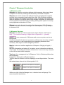
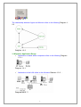
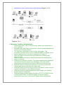
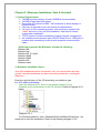
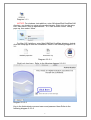
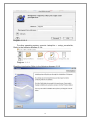
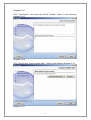
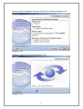
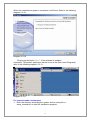
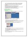
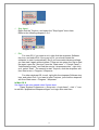
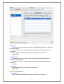
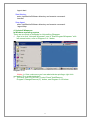
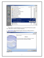
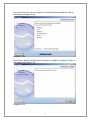
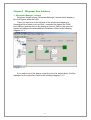
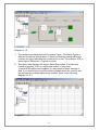
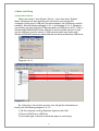
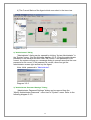
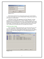
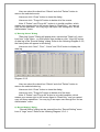
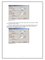
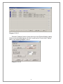
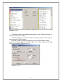
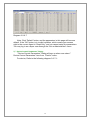
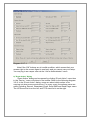
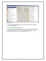
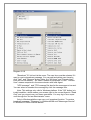
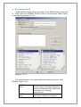
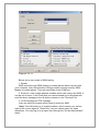
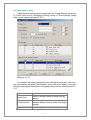
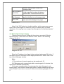
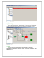
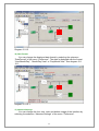
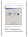
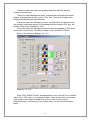
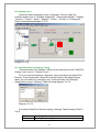
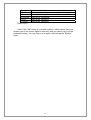
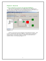
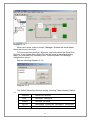
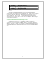
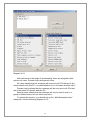
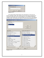
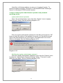
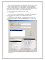
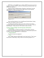
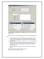
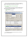
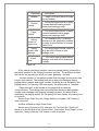
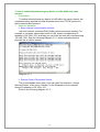
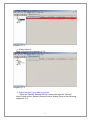
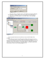
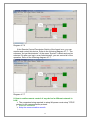
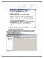
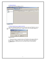
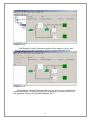
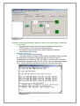
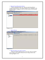
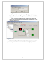
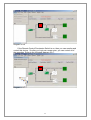
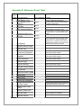
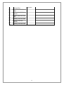
USER MANUAL
GRAVITAS SABRE SERIES
WINPOWER PC SOFTWARE
WWW.UNIPOWERTELECOM.COM
Manual No. WINPOWER-1
01/15/08 winpower-man
© 2008 UNIPOWER Corp.
All Rights Reserved
UNIPOWER Telecom, Division of UNIPOWER Corporation
NORTH AMERICA • 3900 Coral Ridge Drive, Coral Springs, Florida 33065, USA • Tel: +1 954-346-2442 • Fax: +1 954-340-7901 • [email protected]
EUROPE • Parkland Business Centre, Chartwell Road, Lancing BN15 8UE, ENGLAND • Tel: +44(0)1903 768200 • Fax: +44(0)1903 764540 • [email protected]
Table of Contents
Chapter 1 Winpower Introduction.............................................................................4
1. Winpower profile ...................................................................................................4
2. Winpower Structure ...............................................................................................4
3. Winpower Application Range ................................................................................5
4. Winpower Functions & Advantages ......................................................................6
Chapter 2 Winpower Installation, Start & Uninstall ..............................................8
1. System Requirements .............................................................................................8
2. Winpower Installation Steps ..................................................................................8
3. Start/Stop Winpower ............................................................................................14
4. Uninstall Winpower .............................................................................................17
Chapter 3 Winpower User Interface......................................................................21
1. "Winpower Manager" window.............................................................................21
2. Menu and Dialog .................................................................................................23
1) Auto Search Device......................................................................................23
2) "Administrator” Dialog ..................................................................................24
3) "Administrator Password Settings" Dialog................................................24
4) "Event log Viewer" Dialog............................................................................25
5) "Data log Viewer" Dialog .............................................................................26
6) “Record Setting” Dialog ...............................................................................26
7) " Device Control Parameters" Dialog ........................................................30
8) "Event Action" Dialog ...................................................................................31
9) "Broadcast Message Settings" Dialog.......................................................32
10) "Email Settings" Dialog..............................................................................34
11) "SMS Setting" Dialog .................................................................................35
12) "Pager Setting" Dialog ...............................................................................37
13) "Monitor Remote Device" Dialog..............................................................38
14) Bottom image ..............................................................................................39
15) Temp ............................................................................................................39
16) Date Format ................................................................................................40
17) Advance Settings........................................................................................40
18) Language menu..........................................................................................43
19) "Communication Port Settings" Dialog....................................................43
Chapter 4 How to do................................................................................................45
1. How to realize the conversion of the appointed COM port? ...............................45
2. How to realize broadcasting message in LAN.....................................................47
3. How to realize system administrator operation and password modifying realize
..................................................................................................................................50
2
4. How to realize sending event message by email..................................................51
5. How to realize sending event messages by mobile phone....................................52
6. How to realize sending event messages by pager................................................54
7. How to realize telemonitoring any device in LAN within the same network .......56
8. How to realize remote control of any device in different network in LAN ..........59
9. How to realize the Remote Control of any one of the device in Internet .............63
Appendix B---Winpower Event Table .....................................................................67
3
Chapter 1 Winpower Introduction
1. Winpower profile
Winpower is a device monitoring software which supports either stand alone
computers or network (including LAN & Internet) connected computers.
Winpower is used to monitor the intelligent device and safeguard computer
systems from unexpected crash when power fails. With Winpower software,
user can monitor and configure the device on any computer in the same LAN.
With this software, one device can provide multiple computers in network with
security protection simultaneously, including shutting down system in security,
saving application data when AC fails.
Winpower can also be used to monitor the telecompower. With Winpower
software, user can monitor and configure the telecompower on any computer
in the same LAN.
2. Winpower Structure
Winpower is made up of three components: Agent, Monitor and TrayIcon.
Note:The concrete meaning of Agent refer to Appendix A — glossary
explanation.
Agent is the core component of Winpower and runs as a system service on
background.
Communicates with the device, logs events, notifies users of events, arranges
actions according to user's requirement and impending shutdown when
necessary. Also, Agent can be managed by Monitor.
Monitor is the user interface application of Winpower. Relying on Agent, it
gathers
real-time information and status of the device, server information and allows
user to tailor the working parameters of the device. It can run on any computer
on the LAN or stand alone computer.
TrayIcon is the management tool of Winpower. Only in Windows platform has
this component.
It appears in Status Area of System task bar.
TrayIcon has two different icons for displaying current Agent status. The icons
and
the related status refers to the following table 1-2-1:
Indicate the Agent is Stopped.
Indicate the Agent is Running.
Table 1-2-1
While user right clicks the Manager icon, a shortcut menu will popup. The
menu items are listed below:
4
Diagram 1-2-1
The relationship between Agent and Monitor refers to the following Diagram 12-2
Diagram 1-2-2
3. Winpower Application Range
9 Application of stand alone computers refers to the following Diagram
1-3-1:
Diagram 1-3-1
9 Application in the LAN refers to the following Diagram 1-3-2:
Diagram 1-3-2
5
9 Application in the Internet refers to the following Diagram 1-3-3:
Diagram 1-3-3
4. Winpower Functions & Advantages
9 When Agent start, it will run continuously, protect your equipment in
every moment.
9 Uninstall easily and clearly with no trace. Never increase spending on
system and is Green software.
9 You can have a panoramic view of all the information. The
information of utility power, device, loads and battery is shown on the
same window and you can take in everything in a glance.
9 With the function of auto searching and telecom monitoring any
device in LAN.
9 With the function of manual searching and telecom monitoring any
device in Internet.
9 With security protection function. The system administrator password
can be set to prevent others from sabotaging. Only the system
administrator can have the full access, other users can only view.
9 With the function of data auto protection. It can close most of the
running applications and save the related files.
9 With the function of time turning on and off the device, which can give
maximum protection to your computer system.
9 With the function of network shutdown, which supply your network
system maximum protection.
9 With the function of data logging (including UTILITY POWER, device,
LOAD and BATTERY) and event logging, so that the system
administrator can carry out the device system daily maintenance.
6
9 Flexible means of information transfer let you know the device status
at any moment and at everywhere, never miss any one because of
the change of time and place.
¾ With the function of broadcasting messages to every users in the
network.
¾ With the function of sending messages via pager.
¾ With the function of sending messages by EMAIL.
¾ With the function of sending messages via mobile phone sending
SMS.
7
Chapter 2 Winpower Installation, Start & Uninstall
1. System Requirements
¾ 128 MB physical memory at least (256MB is recommended).
¾ 160 MB at least hard disk space.
¾ More than 256 colors and 800 * 600 resolution or above display is
recommended.
¾ The user is required to have the access of administrator.
¾ For Linux or Unix operating system, user must log in system with
“root” account to carry out the installation. And need to reboot
system after installation.
¾ TCP/IP protocol must be installed to support network management.
¾ An available communication port (RS-232 Serial Port or USB port) is
needed while connecting to device with a special communication
cable.
Platforms supported by Winpower include the following:
Windows 98
Windows me
Windows NT 4.0 (sp6)
Windows 2000
Windows 2003
Windows XP
Windows vista
2. Winpower Installation Steps
Note: The installation must be started with “root” account in Linux and Unix
systems! And after installation you must restart the system before running the
Winpower!
Enter the right directory of the CD according your platform type.
For GUI mode environment:
9 Insert the Winpower CD, find out the operate system of your
computer( such as Windows) in the CD directory, Refer to Diagram 2-2-1
below:
Diagram 2-2-1
For Windows platform, enter \Windows\Disk1\InstData\VM directory, run
setup.exe to start the installation. Refer to the following diagram 2-2-2:
8
Diagram 2-2-2
NOTICE: For windows vista platform, enter \Windows\Disk1\InstData\VM
directory, you should run setup.exe as administrator. Right click on the setup
icon, then select “Run as administrator”. If a “user account control” dialog
pops up, then select “Allow”.
For Mac OS X platform, enter \MacOSX\Disk1\InstData directory, double
click the setup.app to start the installation. Refer to the following diagram 2-23-1:
Diagram 2-2-3-1
Click Lock Icon here .Refer to the following diagram 2-2-3-2
Diagram 2-2-3-2
Key in the Administrator account name and password here.Refer to the
following diagram 2-2-3-3
9
Diagram 2-2-3-3
For other operating system, execute ./setup.bin or setup_console.bin,
Refer to the following diagram 2-2-4:
Diagram 2-2-4
Read the introduction Refer to the following diagram 2-2-5
10
Diagram2-2-5
Click “Next”button ,and input the Serial Number, Refer to the following
diagram 2-2-6
Diagram 2-2-6
Click “Next”button ,choose install folder , Refer to the following diagram 2-2-7
Diagram 2-2-7
11
Review the Pre-installation Summary, Refer to the following diagram 2-2-8
Diagram 2-2-8
Installing, Refer to the following diagram 2-2-9
Diagram 2-2-9
12
When the installation program is completed, click Done. Refer to the following
diagram 2-2-10
Diagram 2-2-10
Clicking on the button “Done”. If the software is installed
successful, ”Winpower” application can be found in the Start menu\Programs\,
refer to the following diagram 2-2-11.
Diagram 2-2-11
For console mode environment:
1. Enter the directory according the system and run setup.bin or
setup_console.bin to start the installation program.
13
2.
3.
4.
5.
Note: For UnixWare platform, make sure JRE1.3.1 has been install in
your system, then enter the /GenericUnix directory to start the setup.
Read the information provided, then press ENTER to continue the
installation.
When the installation program is completed, click Done.
Reboot the Linux and Unix system after installation.
The installation will set enviroment variables for Winpower in /etc/profile
file.(details see 'Set environment variable' below)
Reboot the system in order to make this settings valid.
3. Start/Stop Winpower
In Windows operating system
9 Start Agent:
Run the Winpower form Start\Progrom\Winpower will start the TrayIcon
and Agent. Refer to the Diagram 2-3-1 below:
Diagram 2-3-1
The Agent can be start by the following 3 methods:
1) Run the Winpower form Start\Progrom\Winpower will start the TrayIcon
and Agent.refer to Diagram 2-3-1.
2) Right click the Agent icon showing on the bottom right corner of the
display and select the ‘Start Agent’item.refer to Diagram 2-3-2.
Diagram 2-3-2
3) For Windows operate system,Agent can be startup automatically when
the computer startup.
4) To start the Monitor, right click the Belkin APM Software tray icon, and
select Start Monitor, or double click the icon.
9 Start Monitor:
Method One: Right click the TrayIcon and select the "Start Monitor" menu
item.refer to Diagram 2-3-3.
14
Diagram 2-3-3
9 Stop Agent:
Right click the TrayIcon and select the "Stop Agent" menu item.
Refer to the following diagram 2-3-4
Diagram 2-3-4
9 Exit:
For vista OS, if you want to exit, right click the winpower Software
tray icon, and select Exit. Once you exit it, you should restart the
computer to start it automatically. But if you have administrator privilege,
you can start it again without restart. There are two steps: the first to start
the agent, open the “Services” from the “Start menu” > “Control Panel” >
“Administrative tools”, and find the service “winpowermonitor”, right click
on it, select “Start”. The second to start Trayicon, click the winpower soft
from Start menu > Program \ Winpower.
For other windows OS, to exit, right click the winpower Software tray
icon, and select Exit .if you want to start Trayicon, just click the winpower
soft from Start menu > Program \ Winpower.
In Mac OS X
Set Agent to be auto started when System boot:
Open “System Preferences -> Accounts -> Login items” , click “+” icon
to add the “Applications/Winpower/Agent” as Login auto start item.
15
Start Agent:
You can double click the agent link in "Applications/Winpower" directory
to start the Agent.
You can also start it in terminal by enter install directory and execute
command:
enter /opt/monitorSoftware directory and execute command:
./agent start
Start Monitor:
Double click the executable monitor link in "Applications/Winpower"
directory to start Monitor.
You can also start it in terminal by enter install directory and execute
command:
/monitor
Stop Agent:
Enter install directory and execute command:
./agent stop
In Linux and UnixWare:
Start Agent:
enter /opt/MonitorSoftware directory and execute command:
16
/agent start
Start Monitor:
enter /opt/MonitorSoftware directory and execute command:
/monitor
Stop Agent:
enter /opt/MonitorSoftware directory and execute command:
./agent stop
4. Uninstall Winpower
In Windows operating system
There are two kinds of methods for Uninstalling Winpower
9 One is to click “Uninstall Winpower” icon in “Start/Program/Winpower” with
left mouse button, refer to Diagram 2-4-1 below
Diagram 2-4-1
Notice: in Vista, make sure you have administrator privilege, right click
and select “Run as administrator”.
9 The other one is to left click “Control Panel/”Add/Remove
Program”/Change/Remove(C)” button, see Diagram 2-4-2 below:
17
Diagram 2-4-2
Note: Before uninstall Winpower,your must stop all Winpower program
first! Otherwise it can't be uninstall completely.
After left click, the Uninstall Program will pop up a dialog shown on
Diagram 2-4-3 as below:
Diagram 2-4-3
18
Click the “Uninstall” button to begin to uninstall Winpower software, refer to
the following diagram 2-4-4
Diagram 2-4-4
Click “Done” button and Winpower has been uninstalled completely. Refer to
the following diagram 2-4-5
Diagram 2-4-5
19
Note:Before uninstall Winpower,your must stop all Winpower program
first! Otherwise it can't be uninstall completely.
20
Chapter 3 Winpower User Interface
1. "Winpower Manager" window
Winpower Monitor shows "Winpower Manager" window which display a
list of all Agents within the LAN.
There is a tree view on the left side of the window that displays a
hierarchical list of items, such as ‘Root’,‘networks’,the Agents,the COM
port,USB port and the device. By clicking an item for Device, the user can
expand or collapse the associated list of subitems, Refer to the following
diagram 3-1-1:
Diagram 3-1-1
If you select one of the device model from the List, details about it will be
displayed on the right side, Refer to the following diagram 3-1-2
21
Diagram 3-1-2
1. The middle area displays the device status Figure. The Status Figure is
different for various device status. If there is something wrong with some
module, the figure indicating the module will turn red. For example, STS in
above figure. Otherwise, it is green or white.
2. The upper area displays the device Status Description. If at least one
module of inverter, STS, or rectifier has broken, it only show
“inverter/STS/rectifier warning&fault” in red instead of detail warning or
fault. If you would like to know the details, please select the module, and
you will see more details about every module. Refer to the following
diagram 3-1-2-1:
Diagram3-1-2-1
22
2. Menu and Dialog
1) Auto Search Device
When user select " Auto Search Device " menu item from "System"
Menu, Winpower will start searching for the device connect with the
computer’s serial port or USB port (for telecompower, the USB driver must be
installed). See the following diagram 3-2-1-1 and diagram 3-2-1-2. Winpower
can monitor not more than four COM ports and one USB port in a PC. Only in
Windows 98/2000/2003/XP/Vista, Mac OS X and Linux(with kernel 2.6) can
use the USB port. And for device 's USB communication only works with
Windows 2000/XP/Vista and need install the usb driver at directory USB driver.
Diagram 3-2-1-1
Diagram 3-2-1-2
By clicking the item in the tree view, user will get the information as
below, see the following diagram 3-2-1-3:
1) All the computer running Winpower Agent on the LAN.
2) Device COM Port or USB Port.
3) the model type of device to which the Agent is connecting.
23
4) The Current Status of the Agent which user select in the tree view .
Diagram 3-2-1-3
2) "Administrator” Dialog
"Administrator" dialog can be opened by clicking “Act as Administrator” in
the “System” menu. See the following diagram 3-2-2. Enter the administrator
password in the edit box and then click “OK” button. If the password is not
correct, the system will pop up a message dialog to prompt users that the user
password is not correct. If the password is correct, users can get the
administrator access right and set up the Agent.
Note :Initial password is “Administrator”.
Diagram 3-2-2
3) "Administrator Password Settings" Dialog
“Administrator Password Settings” dialog can be opened from the
“Modify Administrator Password” menu item of “System” menu. Refer to the
following diagram 3-2-3:
24
Diagram 3-2-3
Administrator password only can be set by super user in local machine.
If your are not an super user yet, the "Administrator" Dialog will pop up first for
you to log on as administrator.
Users need to enter a new password in the "New Password" text box
and reenter the new password in the "Confirm Password" text box. If the
passwords are not consistent with each other, a message dialog will pop up to
notify the users that the password is not correct and request the users to enter
it once again. If the passwords are consistent with each other and the button
"OK" is selected, the new password will be accepted by the system.
4) "Event log Viewer" Dialog
"Event Log Viewer" Dialog will show when user select "Event Log" menu
item from "Logs" Menu or click buttons from toolbar, or click the “View log”
button of event log in the “Record Setting” dialog, then the “Event Log” dialog
will pop up. See the following Diagram 3-2-4. The dialog displays a list of
history events.
Diagram 3-2-4
25
User can select the check box “Delete” and click "Delete" button to
remove the selected events.
Users can click “Close” button to close the dialog.
Users can click "Purge All" button to delete all of the events.
Note: If “Delete” and "Purge All" button is in invalid condition, which
means your access right to the current Agent is “Read Only”, you can not
carry out the operation. You may log in as super user through the “Act as
Administrator” menu.
5) "Data log Viewer" Dialog
"Data Log Viewer" Dialog will popup when users select "Data Log" menu
item from "Logs" Menu , or click buttons from toolbar or click “View log” button
of data log in the “Record Setting” dialog. Refer to the following Diagram 3-2-5,
the history data will appear in this dialog.
Users can click “Next”, “Prev”, “Home” and “End” button to display the
data log.
Diagram 3-2-5
User can select the check box “Delete” and click "Delete" button to
remove the selected data log.
Users can click “Close” button to close the dialog.
Users can click "Purge All" button to delete all of the data.
Note: If “Delete” and "Purge All" button is in invalid condition, which
means your access right to the current Agent is “Read Only” and you cannot
carry out these operations. You may log in as super user through the “Act as
Administrator” menu.
6) “Record Setting” Dialog
“Record Setting” dialog can be opened from the “Record Setting” menu
item of “Logs” menu. Refer to the following Diagram 3-2-6-1:
26
Diagram 3-2-6-1
The default value of the maximum file length of Event Log Viewer is 32KB
(The maximum value is 1MB)
Click the “View Log” button of the event log in the “Record Setting” dialog
(Refer to the following Diagram 3-2-6-2) to pop up the “Event Log Viewer”
dialog (Refer to the following diagram 3-2-6-3)
Diagram 3-2-6-2
27
Diagram 3-2-6-3
Click the “Settings” button of the event log in the “Record Setting” dialog
(Refer to the following diagram 3-2-6-4) to pop up the “Event Action” dialog,
refer to the following diagram 3-2-6-5.
Diagram 3-2-6-4
28
Diagram 3-2-6-5
The default value of the “Maximum file length” in the “Data Log Viewer” is
32KB (the maximum is 1MB).
The default value of record interval in the “Data Log Viewer” is 60 second
(the maximum is 3600 second).
Click the “View Log” button of data log in the “Record Setting” dialog
(refer to the following diagram 3-3-5-6) to pop up the “Data Log Viewer” dialog
(refer to the following diagram 3-2-6-7).
Diagram 3-2-6-6
29
Diagram 3-2-6-7
Note: Click “Default” button and the parameters in this page will become
default. If the “OK” button is in invalid condition, which means your access
right to the current Agent is “Read Only” and you cannot setup the parameters.
You may log in as a super user through the “Act as Administrator” menu.
7) " Device Control Parameters" Dialog
" Device Control Parameters" Dialog will pop up when user select "
Device Control Parameters" item from “Device” menu.
For device, Refer to the following diagram 3-2-7-1:
30
Diagram 3-2-7-1
Note:If the “OK” buttons are in invalid condition, which means that your
access right to the current Agent is read only and you cannot carry out setup.
You may log in as a super user via the “Act as Administrator” menu.
8) "Event Action" Dialog
“Event Action” dialog can be opened by clicking “Event Action” menu item
in the “Device “ menu or buttons in the toolbar. Refer to the following diagram
3-2-8. In the “Event Action” dialog, users can select which action to be
carrying out when some events occur. For every event, the actions users can
select including: Record, Broadcast, Email, Send SMS and Send Pager users.
The UPS event list is on the left, and TPS event list is on the right.
31
Diagram 3-2-8
Events are divided into three types of icons: Severity (red), Warning
(yellow) and Message (blue).
9) "Broadcast Message Settings" Dialog
“Broadcast Message Settings” dialog can be opened from the “Broadcast
Setting” menu item of “Tools” menu or click broadcast “Setting” button in
“Event Action” Dialog. Refer to the following diagram 3-2-9:
32
Diagram 3-2-9
"Broadcast To" list box list the users. The user item must be selected if it
want to receive broadcast message. You can add and delete user items by
click "Add" and "Remove" button (Note: the "All Users" and "Domain User"
item can not be deleted). "All Users" means all computers in LAN. "Domain
User" means computers in the same domain with local Agent.
"UPS message" and “TPS message”list box list the messages to be sent.
You can select or unselect the message by click the message item.
Note: This settings only valid in Windows platform. If the "OK" button is in
invalid condition, which means your access right to the current Agent is "Read
Only" and you cannot carry out these operations. You may log in as a super
user through the "Act as Administrator" menu.
Only in Windows platform can carry out broadcast function. To receive
broadcast message, "Winpopup" in Windows95/98 and "Messenger Service"
in Windows NT/2000 must be started.
33
10) "Email Settings" Dialog
“EMail Settings” dialog can be opened from the “EMail Setting” menu item
of “Tools” menu or click EMail “Setting” button in “Event Action” Dialog. Refer
to the following diagram 3-2-10:
Diagram 3-2-10
The included items of the email parameter setting are shown in the
following Table 3-2-15:
SMTP Server
Name
SMTP Account
Name
This is the mail server, which is used
to send emails to the appointed users.
Enter the IP address of the SMTP mail
server here. For example,
smtp.163.com
This is the account number for logging
in the server. Enter the complete
34
Password
address format here. For example,
[email protected]
Input the SMTP account password in
needed.
Table 3-2-10
“Receiver EMail Address” list box list the email addresses which will
receive the email. Click "Add" button to add an email address item. Select an
address item and click "Remove" button will delete this item. Selected an
email address item and click the "Test" button will send a test email to this
email address.
“UPS message” and “TPS message” list box list the messages to be
sent. You can select or unselect the message by click the message item.
All of the SMTP parameter default value is naught, and it can only be
setup in the local Agent. To send email to the appointed user, the SMTP
server name or IP address must be set, or the email will not be sent out.
Note: If you want to send email via Internet, you must have a SMTP
account number in the Internet. If the “OK” button is in invalid condition, which
means that your access right to the current Agent is read only and you cannot
carry out the parameter setting. You may log in as a super user through the
“Act as Administrator” menu.
11) "SMS Setting" Dialog
“SMS Setting” dialog can be opened from the “SMS Setting” menu item of
“Tools” menu or click Send SMS “Setting” button in “Event Action” Dialog.
Refer to the following diagram 3-2-11:
35
Diagram 3-2-11
Below is the use remark of SMS setting:
1. Sender
SMS is sent through GSM modem or mobile phone which connect with
your computer. User should select COM port which is being used by GSM
Modem or mobile phone. Then set baud Rate of this COM port.
2. Receiver: is the mobile phones numbers which can receive the SMS. It
can be one or more. If the Event that you have selected occur Winpower will
send the short message to the all phone numbers in the "Receiver" list.
3. UPS message and TPS message
User can select the events which need to inform by SMS.
Note: If the OK button is in invalid condition, which means your access
right to the current Agent is "Read Only" and you cannot carry out these
operations. You may log in as a super user through the "Act as Administrator"
menu.
36
12) "Pager Setting" Dialog
“Pager Setting” dialog can be opened from the “Pager Setting” menu item
of “Tools” menu or click SendPager “Setting" button in ""Event Setting" Dialog.
Refer to the following diagram 3-2-12:
Diagram 3-2-12
To configure the pager parameters user must have full access. User can
get full access by selecting "Administrator" menu item from "Setup" menu and
providing right Agent Password in the popup dialog. See the following table 32-17:
Parameter
Description
Modem Port
Select COM port which is being used by
Modem.
Access Number
For some pager service, a delay is needed
between dialing access number and Pager
Number.
Pager Number
For some pager service, a delay is needed
37
between dialing pager number and
message code.
For extension line, it is always necessary
dailing number to
to dial a specified number and delay a
exterior line
specified time to access Exterior Line.
dailing number
after message
For some pager service, need to dial a
specified number to end message code.
Event Code
The event code is dialed as the message
code and will be displayed on pager.
Table 3-2-12
Note: If the “OK” button is in invalid condition, which means your access
right to the current Agent is “Read Only” and you cannot carry out these
operations. You may log in as a super user through the “Act as Administrator”
menu.
13) "Monitor Remote Device" Dialog
"Monitor Remote Device" Dialog will show when user select "Monitor
Remote Device " menu item from "Monitor" menu. Refer to the following
diagram 3-2-18-1:
Diagram 3-2-13-1
Enter the IP address of an Agent to be monitored and press OK button. If
this agent exist it's information will be displayed below the "WAN" node in the
tree view of Manager window.
Note:
1) The maximum of remote agent can be monitored is 32.
2) If Winpower can't communicate with a remote agent in 6 minutes, this
agent will be deleted automatically.
3) You can manually delete a remote agent by select this agent node
below "WAN", then click the mouse right button to show a delete pop up menu,
select "Delete" menu item to remove it. Refer to the following diagram 3-2-132:
38
Diagram 3-2-13-2
14) Bottom image
If you select the submenu “BottomImage” of the menu item “Preference”,
you can change the bottom image of the interface. See diagram 3-2-14-1:
Diagram 3-2-14-1
15) Temp
You can make the interface show the centigrade or Fahrenheit
temperature by selecting the submenu “Temp” of the menu “Preference”. See
diagram 3-2-15
39
Diagram 3-2-15
16) Date Format
You can change the displayed date format by selecting the submenu
“DateFormat” of the menu “Preference”. The date is displayed with the format
“Year/Month/Day”, “Month/Day/Year” or “Day/Month/Year”. See diagram 3-216-1:
Diagram 3-2-16-1
17) Advance Settings
You can change the font, size, color and bottom image of the interface by
selecting the submenu “Advance Settings” of the menu ”Preference”.
40
“Advance Settings” dialog consists of two views “General” and
“BottomImage”.
In the “General” view:
You can change the color of general text, data and warn text by clicking
the color you want.
Users can select font from the “Font” list. Refer to the following diagram
3-2-17-1:
Diagram 3-2-17-1
Note: If you click “Default” button, the parameters in this view will be
turned into default value.
If the “OK” button is in invalid condition, which means that your access
right to the current Agent is Read Only and you cannot carry out the
parameter setup. You may log in as a super user through the “Act as
Administrator” menu.
In the “BottomImage” view:
If you click “None” box, the bottomimage of the interface is “background
color”.
Users can select the color that they want by clicking “Color” box
41
Users can select the color and gradient direction that they want by
clicking “Gradient” box
Users can select background color, character size and light and shade
degree of background text by clicking “Text” box. The bottom image is the
background that has the appointed text.
Users can select the background color, the grid offset, the grid size and
the grid light and shade degree in the background by clicking “Grid” box, the
bottom image of the interface is “Grid”.
Users can select the background pictures from the popped up list box by
clicking the “Picture” box, the bottom image of the interface is “Picture”.
Refer to the following diagram 3-2-17-2
Diagram 3-2-17-2
Note: Click “Default” button, the parameters in this view will turn to default
value. If the “OK” button is in invalid condition, which means that your access
right to the current Agent is Read Only and you cannot carry out the
parameter setup. You may log in as a super user via “Act as Administrator”
menu.
42
18) Language menu
Users can select languages in the “Language” menu to make the
interface display text in “Chinese(Traditional)”, “Chinese(Simplified)”, “English”,
“German”, “French”, “Italian”, “Spanish”, “Polish”, “Turkish” or “Portuguese”.
Refer to the following diagram 3-2-18
Diagram 3-2-18
19) "Communication Port Settings" Dialog
"Communication Port Settings" dialog can be opened from the "COM Port
Setting" menu item of "System" menu.
For Linux and Unix platform, Winpower can't auto detect the Serial Port
Devices. If the System has a Serial Port not be found in the default setting
table, you must add it by manually in the "Communication Port Settings"
dialog before using it. following Table following diagram 3-2-19:
Diagram 3-2-19
The default Serial Port Devices setting: following Table following Table 32-219
Platform
Linux
Serial Port Devices
/dev/ttyS0 /dev/ttyS1.
43
Solaris
HP-UX
AIX
UnixWare
Tru64
FreeBSD
/dev/ttya /dev/ttyb
/dev/tty0p0 /dev/tty1p0 /dev/tty0p1 /dev/tty0p2
/dev/tty0 /dev/tty1
/dev/tty1A /dev/tty2A
/dev/tty00 /dev/tty01
/dev/ttyd0 /dev/ttyd1
Table 3-2-19
Note: If the "OK" button is in invalid condition, which means that your
access right to the current Agent is read only and you cannot carry out the
parameter setting. You may log on as a super user through the "System"
menu.
44
Chapter 4 How to do
1. How to realize the conversion of the appointed COM port?
When the PC with Winpower has multiple serial ports, Winpower can
allow the users to change the current connected serial ports of the Device via
“Auto search Device” menu. See the following Diagram 4-1-1:
Diagram 4-1-1
There is a tree view in the left displays a hierarchical list of items , such
as ‘Root’,‘networks’,the Agents,the COM port and the device models. By
clicking an item, the user can expand or collapse the associated list of
subitems, Refer to the following diagram 4-1-2:
45
Diagram 4-1-2
When user select a device model ,"Manager" Window will show details
about the device in the right .
For Linux and Unix platform, Winpower can't auto detect the Serial Port
Devices. If the System has a Serial Port not be found in the default setting
table, you must add it by manually in the "Communication Port Settings"
dialog before using it.
See the following Diagram 4-1-3:
Diagram 4-1-3
The default Serial Port Devices setting: following Table following Table 41-1:
Platform
Serial Port Devices
Linux
/dev/ttyS0 /dev/ttyS1.
Solaris
/dev/ttya /dev/ttyb
HP-UX
/dev/tty0p0 /dev/tty1p0 /dev/tty0p1 /dev/tty0p2
AIX
/dev/tty0 /dev/tty1
46
UnixWare
/dev/tty1A /dev/tty2A
Tru64
/dev/tty00 /dev/tty01
FreeBSD
/dev/ttyd0 /dev/ttyd1
Table4-1-1
Note: For the first time start Agent it takes more time than later to
communicate with the device.And the softerware will keep a record of device
information.Next time ,Winpower will start according to the last record. If
device COM Port , device model or slave address being changed,user
should click "Auto Search Device " menu item from "System" Menu and get
correct device information.
2. How to realize broadcasting message in LAN
Winpower has the function of sending the event message to the
customers in time via Windows message service. The concrete operation
refers to the notes in Section 13 of Chapter 3 (“Broadcast Message Settings”
Dialog) and Appendix B (Winpower Event Table). See the following diagram
4-2-1:
47
Diagram 4-2-1
With reference to the range of broadcasting, there are altogether three
options: all users, Domain users and special users.
All users indicate that the message will be sent to all PCs that are in the
same network with this PC, no matter whether it is in the same domain with it.
Domain users indicate that the message will be only sent to all PCs that
are in the same NT domain with this PC.
Special users indicate that the message will only be sent to one or a
group of defined users, but not others any more.
To realize this function, you should set up the “Add Brdoadcast User”
dialog first, see the following diagram 4-2-2:
48
Diagram 4-2-2
In the above dialog, after setting up the information of users who will
receive messages, select “OK” button to exit from the setup of special users.
The names of the setup users will be displayed in the “Broadcast Message
Settings” dialog. Select the events that will be sent to the users. After pressing
the “OK” button, they will become effective. See the following diagram 4-2-3:
Diagram 4-2-3
49
Note:Only in Windows platform can carry out broadcast function. To
receive broadcast message, "Winpopup" in Windows95/98 and "Messenger
Service" in Windows NT/2000 must be started.
3. How to realize system administrator operation and password
modifying realize
system administrator operation
Open “Act as Administrator” menu item from “System” menu to popup
“Administrator” dialog. See the following diagram 4-3-1:
Diagram 4-3-1
Enter the system administrator password in the dialog and press the “OK”
button to finish the setting. If the password is correct, you can get the access
right of the administrator to set up the Agent. If the password is not correct,
alert box will popup. See the following diagram 4-3-2:
Diagram 4-3-2
Modifying the system administrator password
Open the “Modify Administrator Password” menu from the “System” menu
to popup the “Administrator Password Settings” dialog. This menu is valid
within the local Agent. See the following diagram 4-3-3:
Diagram 4-3-3
50
Enter the new password in the “New Password” edit box; reenter it in the
“confirm password” edit box. Press the “OK” button to finish the setting.
Note: If the “OK” button is in invalid condition, which indicates that the
access right to the current Agent is “Read Only”, you cannot operate it. You
may log in as a super user from “Act as Administrator” menu.
4. How to realize sending event message by email
9 Precondition
When event occurs, the precondition for realizing sending message by
email is to connect the computer with Winpower to the Internet.
9 Steps
Setup “EMail Service”: Open the “Email setting” menu item from the
“Tools” menu to pop up the “Email Settings” dialog. Refer to the following
diagram 4-4-1:
Diagram 4-4-1
51
SMTP Server is the SMTP server address; SMTP User is the account for
logging in the server. If SMTP mail server need password authentication user
should Input password.
Setup the Receiver EMail Address: Select the “Add” button from the
“Email Settings” dialog, and then pop up “Add Receiver Email Address”
dialog(Refer to the following diagram 4-4-2).
Diagram 4-4-2
Enter the “Email Address” in the “Add Receiver Email Address” dialog,
then select “OK” button to save it and exit.
Completing Event Setting: Select one of the events from the “Send
message”; then select the user that has been set up in the mail of “Receiver
Email Address”. Finally select the “OK” button to save it and exit.
5. How to realize sending event messages by mobile phone
9 Precondition
The precondition of sending messages by mobile phone is that the
computers with Winpower must have at least one communication ports which
is used to connect to GSM Modem or mobile phone.
9 Events supported
For TPS, all events are supported.
9 Steps
Setup “SMS”: Open the “SMS setting” menu item from the “Tools” menu
to pop up the “SMS Setting” dialog. Refer to the following diagram 4-5-1:
52
Diagram 4-5-1
Below is the use remark of SMS Setting: Refer to the following diagram 410-3.
1. Sender: SMS is sent through GSM modem or mobile phone which
connect with your computer. User should select COM port which is
being used by GSM Modem or mobile phone. Then set baud Rate of
this COM port.
2. Receiver: is the mobile phones numbers which can receive the SMS.
It can be one or more. If the Event that you have selected occur,
Winpower will send the short message to the all phone numbers in
the "Receiver" list.
3. Send message: Use can select the events which need to inform by
SMS .
Finally select the “OK” button to save it and exit.
Another method to select Event Code:
53
Select one of the events (For example, AC Fail) from the “Event List”,
which is on the left side of the “Event Action”; then select “Send SMS” on the
right side. Finally select the “OK” button to save it and exit.
6. How to realize sending event messages by pager
9 Precondition
When event happens, the precondition of sending messages by pager is
that the computers with Winpower must have at least one communication
ports which is used to connect to MODEM.
9 Events supported
For TPS, all events are supported.
9 Steps
Setup “Pager”: open the “Pager setting” menu item from the “Tools” menu
to pop up the “Pager Setting” dialog. Refer to the following diagram 4-6-1:
Diagram 4-6-1
In the “Pager Setting” dialog, the parameters which can be setup is
shown in the following Table 4-6
54
Parameter
Modem
Port
Description
Select COM port which is being
used by Modem.
Access
Number
For some pager service, a delay
is needed between dialing access
number and message code.
Pager
Number
For some pager service, a delay
is needed between dialing pager
number and message code.
dailing
number to
exterior line
For extension line, it is always
necessary to dial a specified number
and delay a specified time to access
Exterior Line.
dailing
number after
message
For some pager service, need to
dial a specified number to end
message code.
Event
Code
The event code is dialed as the
message code and will be displayed
on pager.
Table 4-6
If the exterior line phone number cannot be dialed directly, please fill in
the switch number in the “Dailing to exterior line bar”. The waiting time after
dial can be set according to what you need, generally 1 second.
“Access number” is the station number that the pager joined (which can
only be auto station). The waiting time is the delay time between dialing
paging station number and pager number, this delay time is decided by the
paging station, for Liantong 192 auto station, the waiting time is 1 second.
“Pager Number” is the number of the pager that accepts the
communication. The waiting time is the delay time between dialing pager
number and message code (paging message content), the delay time is
decided by the paging station, for Liangtong 192 auto station, the waiting time
is 1second.
Select Event Code from the “Pager Setting” and select “OK” button to
save it and exit.
Another method to select Event Code:
Select one of the events (For example, AC Fail) from the “Event List”,
which is on the left side of the “Event Action”; then select “Send Pager” on the
right side. Finally select the “OK” button to save it and exit.
55
7. How to realize telemonitoring any device in LAN within the same
network
9 Precondition
To realize telemonitoring any device in LAN within the same network, the
computers being required to setup Winpower must have TCP/IP protocol in
their communication protocol.
9 Steps for realization
¾ Keep network communication smooth
test with network command PING under command prompt window. For
example, a computer named stkr-user2 in LAN, whose corresponding IP
address is 192.168.1.221, and then you can finish the test with command ping
192.168.1.221. See the following Diagram 4-7-1: which indicates that the
physical link of LAN is smooth.
Diagram 4-7-1
¾ Remote Control Permission Switch
This is a selectable menu item. User can open the submenu “Accept
Remote Device” of the menu “Monitor” in the Winpower in the computer
whose IP address is 192.168.1.221 .
Refer to the following diagram 4-7-2:
56
Diagram 4-7-2
¾ Startup Monitor
Refer to the following diagram 4-7-3:
Diagram 4-7-3
¾ Select the device you want to monitor
Open the “Monitor Remote Device” menu item from the “Monitor”
menu to pop up the “Monitor Remote Device” dialog. Refer to the following
diagram 4-7-4:
57
Diagram 4-7-4
User can enter a computer name or IP address in the popup "Monitor
Remote Device " Dialog. Click on the “OK” button to finish the setting.
Now You can find the device in the WAN, Refer to the following
diagram 4-7-5
Diagram 4-7-5
You can select the device from the tree view on the left side of the
window.
If the Remote Accept Control Permission Switch of the Agent is not on,
you can only monitor but not control. Refer to the following diagram 4-7-6: The
submenu “Act as Administrator” of the menu “System” is gray and cannot be
selected. So if you do not log in as an administrator, you cannot control all of
the operation, Refer to the following diagram 4-7-6.
58
Diagram 4-7-6
If the Remote Control Permission Switch of the Agent is on, you can
monitor and control this device. Refer to the following diagram 4-7-7: The
submenu “Act as Administrator” of the menu “System” is black and can be
selected. So after you log in as an Administrator, you can control all of the
operation, Refer to the following diagram 4-7-7.
Diagram 4-7-7
8. How to realize remote control of any device in different network in
LAN
¾ The computers being required to setup Winpower must setup TCP/IP
protocol in the communication protocol.
9 Steps for realization
¾ Keep the communication smooth:
59
test with network command PING under command prompt window. For
example, a computer named stkr-user2 with IP address 192.168.2.228, you
can test with command “ping 192.168.2.228”. See the following Diagram 4-8-1:
which indicates that the physical link of LAN is smooth.
Diagram 4-8-1
¾ Remote Control Permission Switch
This is a selectable menu item. User can open the submenu “Accept
Remote Device” of the menu “Monitor” in the Winpower in the computer
whose IP address is 192.168.2.228 .
Refer to the following diagram 4-8-2:
Diagram 4-8-2
60
¾ Startup Monitor
Refer to the following diagram 4-8-3:
Diagram 4-8-3
¾ Select the device you want to monitor
Open the “Monitor Remote Device” menu item from the “Monitor” menu to
pop up the “Monitor Remote Device” dialog. Refer to the following diagram 48-4:
Diagram 4-8-4
User can enter a computer name or IP address in the popup "Monitor
Remote Device " Dialog. Click on the “OK” button to finish the setting.
Now You can find the device in the WAN, Refer to the following
diagram 4-8-5.
61
Diagram 4-8-5
If the Remote Control Permission switch of this Agent is not on, then
you can only monitor but not control. See the following diagram 4-8-6.
Diagram 4-8-6
If the Remote Control Permission Switch is on, then you can monitor and
control this device. So after you login as a super user, you can control all of
the operation, Refer to the following diagram 4-8-7.
62
Diagram 4-8-7
9. How to realize the Remote Control of any one of the device in Internet
9 Precondition
¾ The computers being required to setup Winpower must setup
TCP/IP protocol in the communication protocol.
¾ The computer being required to setup Winpower has been
connected to the Internet.
9 Steps for realization
¾ Keep the communication smooth
test with network command PING under command prompt window.
For example, a computer named stkr-user2 in internet, whose
corresponding IP address is 202.103.190.87, and then you can finish
the test with command ping 202.103.190.87. See the following Diagram
4-9-1: which indicates that the physical link of Internet is smooth.
Diagram 4-9-1
63
¾ Remote Control Permission Switch
This is a selectable menu item. User can open the submenu
“Accept Remote Device” of the menu “Monitor” in the Winpower in the
computer whose IP address is 202.103.190.87.Refer to the following
diagram 4-9-2:
Diagram 4-9-2
¾ Startup Monitor
Refer to the following diagram 4-9-3:
Diagram 4-9-3
¾ Select the device you want to monitor
Open the “Monitor Remote device” menu item from the “Monitor”
menu to pop up the “Monitor Remote Device” dialog. Refer to the
following diagram 4-9-4:
64
Diagram 4-9-4
User can enter a computer name or IP address in the popup
"Monitor Remote Device " Dialog.click on the “OK” button to finish the
setting.
Now you can find the device in the WAN, You can select the
device from the tree view on the left side of the window. Refer to the
following diagram 4-9-5.
Diagram 4-9-5
If the Remote Control Permission switch of this Agent is not on, then
you can only monitor but not control. See the following diagram 4-9-6.
65
Diagram 4-9-6
If the Remote Control Permission Switch is on, then you can monitor and
control this device. So after you login as a super user, you can control all of
the operation, Refer to the following diagram 4-9-7.
Diagram 4-9-7
66
Appendix B---Winpower Event Table
Serial
Number Event Description
1
2
UPS Battery Low
UPS Battery Time
Exhaust
3
UPS Fail
4
UPS Output Overlad
Type of Message Remarks
Serious
Can be set as no shutdown system
through “Shutdown parameter”
Serious
Can set battery backup time through
“Shutdown parameter”
Serious
Serious
Output load is more than 110%
The connection of communication cable
is not good, or communication port
fault.
Warning
6
Communication Lost
7
AC Fail
Warning
Warning
8
On Bypass
9
Bypass without output
10
Self-test Fail
Phase sequence
incorrect in Bypass
Battery switch not
engaged
11
12
13
Load unbalance
14
Load too high
15
Internal warning
16
Maintain cover is open
17
AC Restore
18
19
20
21
22
23
24
25
26
Communication Create
Agent Start
Agent Stop
System be shutdown
System be Shutdown
by Other Agent
Special date Close
UPS
Weekly Close UPS
Self-test Start
Self-test cancel
UPS will be switched to bypass mode
for the reason of overload, hardware
fault and so on. Online UPS is also in
bypass mode when it is off, at this time
UPS has no protection function.
Warning
Warning
Three-phase UPS support
Warning
Three-phase UPS support
Warning
Three-phase UPS support
Warning
Warning
Three-phase UPS support
Warning
Information
Information
Information
Information
Information
Information
.
.
.
.
.
Set the Agent need to be in response to
through”Shutdown parameter”.
Information
.
Information
Information
Information
67
.
Self-test begins immediately.
.
27
28
29
30
31
32
33
Sel-test End
Special date Self-test
Start
Special date Self-test
Cancel
Special date Self-test
End
Information
.
Information
.
Information
.
Information
Monthly Self-tes Start
Information
Monthly Self-test
Cancel
Monthly Self-test End
.
Information
Information
68
.
.
.