1
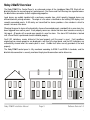
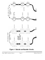
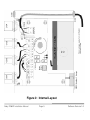
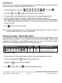
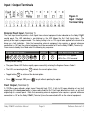
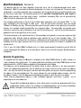
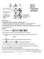
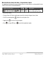
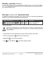
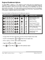
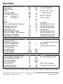
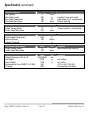
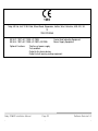
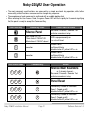
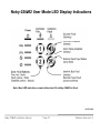
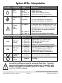
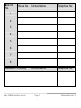
Installation Manual
Please read these instructions carefully and retain them in a safe
place for future reference.
IX-02-151
Noby-220iiR2 Installation Manual
-
Page 1
-
Software Revision1-0
-
Contents
Page
Noby-220iiR2 Overview
Installation and Commissioning
Location and mounting the Noby-220iiR2
6
Connecting the 230VAC supply
6
First power up
7
Connecting the detectors
7
Connecting the external sounders
7
One-man test
8
Automatic Re-sound Option
8
Input / Output Terminals
9
External Fault Input
9
Fault Output
9
interlink Data Bus
10
interlink Programming
10
LED Strobe / Lamp Output
13
Relay Output
13
Engineer Disablement Options
Panel Behaviour
14
15
Audible alarms, faults & warnings
15
Panel Reset
15
LED Lamp and 230VAC Mains Loss
Maintenance
Troubleshooting
Warnings & Cautions
Specification
User Operation
LED Display Indications
Noby-220iiR2 Installation Manual
-
3
6
Page 2
-
15
15
16
17
18
21
22
Software Revision1-0
-
Noby-220iiR2 Overview
The Noby-220iiR2 Fire Control Panel is an enhanced version of the standalone Noby-220, fitted with an
interlink data bus for connecting up to 8 control panels. Fire Alarms and Fault Warnings are signalled across
the interlink bus connection to alert neighbouring properties.
Local alarms are audibly signalled with a continuous sounder tone, whilst remotely triggered alarms are
differentiated with pulsing sounders. The origin of a fire alarm is identified on the latching LED display at all
remotely connected panels. A 60s delay on transmitted fire alarms provides a time window in which to
cancel a nuisance false alarm.
Silencing the panel-in-alarm will automatically silence all connected panels, provided that no new alarm has
been triggered from another panel. Each property owner can silence their own local sounders manually at
their panel. All panels will re-sound upon receipt of a new fire alarm. Fire alarm LED indication is latched
until a Panel Reset is performed at each individual property.
Fault LED indications remain latched at the local property until the panel is reset. Fault conditions
originating from remote properties are displayed in real-time at the local panel, and the LED indications are
automatically cleared when the remote panel is reset. Audible fault tones are only provided at the local
property.
The Noby-220iiR2 control panel is fully monitored according to EN54-2 and EN54-4 standards, and the
interlink data connection is securely monitored for physical disconnection and/or data errors.
Noby-220iiR2 Installation Manual
-
Page 3
-
Software Revision1-0
-
Figure 1: Detector and Sounder Circuits
Noby-220iiR2 Installation Manual
-
Page 4
-
Software Revision1-0
-
Figure 2: Internal Layout
Noby-220iiR2 Installation Manual
-
Page 5
-
Software Revision1-0
-
Installation and Commissioning
This equipment is to be installed, serviced and maintained by a suitably qualified technical person with the
requisite knowledge of electrical and fire safety installations.
Location and Mounting
It is best to locate the Noby-220iiR2 in a public space, e.g. a hallway or landing area, where the LED
Strobe/Lamp is visible and the internal alarm sounder can be clearly heard. Another consideration is to
position the panel to make most effective use of the LED Strobe/Lamp, which switches on automatically in
the event of mains power loss.
The Noby-220iiR2 is intended for indoor use only, and must be sited in a dry environment. Do not site the
Noby-220iiR2 outside, or in any location where it may become exposed to damp or freezing conditions.
All components are selected to operate within their specification when the environmental conditions outside
the enclosure comply with class 3k5 of EN60721-3-3:1995; temperature range -5°C to +40°C; 95%RH. The
enclosure is rated at IP30, which offers protection against tools and wires greater than 2.5mm width, but no
protection against liquids.
Mount the Noby-220iiR2 securely onto a flat solid surface at the three fixing points denoted by ‘MH’ in
Figure-2, using wall fixings appropriate for the material. In some situations it may be desirable to recess the
panel into a hollow section wall, in which case the ‘Noby-220iiR2 Flush Mounting Kit’ provides the necessary
fixing harness and stainless steel frame.
Connecting the 230VAC supply
Connect the 230VAC to the Noby-220iiR2, paying strict attention to local wiring regulations. A readily
accessible disconnect device shall be incorporated into the building installation wiring. Feed the cable
securely through the rear cable-entry hole CE2, or via a 20mm cable-gland CG4.
Alternatively a 3-core 230VAC flexible cord can be fed through CG5 (top) or CG6 (bottom) using the strain
relief bush supplied (suitable for cable diameters 6.2mm to 7.4mm). In this case ensure that the cord is
connected to the building installation wiring via a readily accessible disconnect device fitted with a 2A fuse.
Strip back the outer sheath of the cable 25mm and then strip back each inner core 6mm, such that
the cable double insulation is preserved inside the enclosure to within 25mm of the screw
terminals.
The Noby-220iiR2 is Class-1 equipment and shall be earthed. Connect the earth core of the
incoming cable to the earth point on the enclosure. Consult a qualified electrician if there are
doubts concerning electrical safety.
Noby-220iiR2 Installation Manual
-
Page 6
-
Software Revision1-0
-
First power up
It is recommended that the Noby-220iiR2 is first powered up with the End Of Line devices still connected to
the screw terminal block at the panel, as supplied from the factory. This will help to establish that the panel
is functioning OK before connecting any external devices.
•
•
•
•
•
•
•
•
•
•
Switch off or disconnect the 230VAC supply.
Position the battery as shown in Figure-2, with the -'ve terminal to the rear of the enclosure.
Connect the battery terminals, observing strict battery polarity.
Press the pushbutton marked “Batt Start”.
The panel powers up indicating a PSU fault, accompanied by a fault tone (2 beeps every 4s).
The LED Strobe Lamp is automatically activated due to there being no 230VAC at this time.
Switch on the 230VAC supply to the panel.
The green Power LED blinks (occults) every 4 secs, indicating that 230VAC has been absent (memory).
Perform a Panel Reset (refer to User Operation on page 21).
The Noby-220iiR2 should now be in standby mode with a steady green Power LED and blue backlight.
Connecting the detectors (Figure 1)
•
•
•
•
•
•
•
•
Up to a maximum of 10 detectors can be connected to each zone.
Up to a maximum of 10 call-points can be connected to each zone.
Ensure that the detectors are within specification to operate at 10.5 volts.
Use detector bases fitted with a schottky diode.
Connect the detectors and call-points in a straight daisy-chain manner, with no spurs or loops.
The recommended maximum cable length on each circuit is 100m.
Maintain strict polarity from the panel, and from one detector to the next.
Remove & re-connect the factory fitted EOLC at the outermost detector base.
Connecting the external sounders (Figure 1)
• The total combined sounder circuit current available across both circuits, is 150mA.
e.g. up to 10 sounders can be connected with a current draw of 15mA each.
• The sounders must compatible with conventional fault monitoring (polarised).
• Ensure that the sounders are within specification to operate at 10.5 volts.
• Connect the sounders in a straight daisy-chain manner, with no spurs or loops.
• The recommended maximum sounder cable length is 100m per loop.
• Maintain strict polarity from the panel, and from one sounder to the next.
• Remove & re-connect the factory fitted EOLR at the outermost sounder.
Noby-220iiR2 Installation Manual
-
Page 7
-
Software Revision1-0
-
One-man test
The one-man test is a test facility to aid commissioning and testing of the system, allowing the installer to
walk-test the system and trigger each detection device in turn.
• Enter the Engineer Access Code-2
1
• Press either
and/or
followed by
.
2 to toggle on/off the desired zone/s for testing.
• The selected zone/s are indicated by rotating LED patterns on the corresponding pushbutton/s.
• You now have 90s to trigger the first device, and 90s thereafter to trigger the next device.
• Each triggered device will pulse the sounders and flash the red zone LEDs until the test alarm condition is
clear. The panel automatically resets the detectors. Note that the relay output remains unaffected by the
one-man test mode.
• Press
to exit the one-man test mode.
Note: The panel automatically kicks back to normal standby User Mode after 90s of no activity, or if there is
a real fire condition detected on a zone not being tested.
Automatic Re-sound – Programmable Option
It is a requirement of EN54-4 that it must be possible to configure the fire panel to automatically re-sound
following an alarm in another zone. This is the default factory setting for the Noby-220iiR2. The panel can be
reconfigured to automatically re-sound following an alarm only in the same zone by clearing the option
switch. From normal standby User Mode enter the following key sequence:
Engineer Access Code-1
1
2
1
2
Select
Toggle
1
2
2
Auto Re-sound Option
LEDs Off= No Auto Re-sound
LEDs On= Auto Re-sound*
* Factory default setting
• The green Power LED flashes rapidly upon successfully entering the Engineer Access Code-1.
• The LEDs surrounding button
• Toggle button
• Press
2 to set/unset the desired option.
to accept OR press
Noby-220iiR2 Installation Manual
-
2 indicate the current option status.
to quit without updating the option.
Page 8
-
Software Revision1-0
-
Input / Output Terminals
Figure 3:
Input / Output
Terminal Strip
External Fault Input (Terminal 1)
The Fault Input terminal permits a fault signal from external equipment to be indicated on the Noby-220iiR2
control panel. The LED indication is non-latching i.e. the LED follows the Ext. Fault Input status. The
polarity of the input is programmable. The factory setting is for a +12V signal to be applied to the terminal to
bring up a fault indication. Note that connecting external equipment also requires a ground reference
connection i.e. 0V from the external equipment must be connected to 0V on the Noby-220iiR2 (Terminal 4).
From normal standby User Mode enter the following key sequence:
Engineer Access Code-1
1
2
2
1
Select
Toggle
1
1
2
Fault Input Polarity Option
LEDs Off= +12V applied*
LEDs On= +12V removed
* Factory default setting
• The green Power LED flashes rapidly upon successfully entering the Engineer Access Code-1.
• The LEDs surrounding button
• Toggle button 1
• Press
1
indicate the current option status.
to set/unset the desired option.
to accept OR press
to quit without updating the option.
Fault Output (Terminal 2)
A 12V/20ma open-collector output signal. Normally high (12V), it falls to 0V upon detection of any fault
originating at the local panel only i.e. does not include the Ext. Fault Input, interlink bus faults, or any fault
originating at a remote panel. Note that connecting external equipment also requires a ground reference
connection i.e. 0V on the Noby-220iiR2 (Terminal 4) must be connected to 0V on the external equipment.
Noby-220iiR2 Installation Manual
-
Page 9
-
Software Revision1-0
-
interlink data bus (Terminal 3)
The interlink data bus has been laboratory tested with up to 1km of standard low-grade alarm cable
(92mohm/m 160pF/m), connected in different configurations i.e. linear, star, clustered etc.. These tests were
conducted in a simulated electrically noisy environment, but we appreciate that real world installations can
be more harsh and varied. We therefore specify that the maximum installed interlink cable length is
250m, which provides a four fold safety margin. Installations exceeding 250m are not guaranteed by
Noby UK and are undertaken at the installer's risk.
The overiding limiting factor is that the total installed cable capacitance must not exceed 100nF i.e. the
pF/m multiplied by the total length of cable used.
Also, the total circuit resistance must not exceed
100ohms (or 50ohms per leg). Wherever possible avoid running the cable in close proximity to transmitter
devices, or in conduits containing potentially noisy electrical cables. Screened cable may provide some
immunity in excessively noisy environments (e.g. near RF transmitters etc.) - with the screen connected to a
good clean earth at one point only on the system.
The data connection is low speed and there is little advantage to be gained in using more expensive high
speed data cable, although national regulations might stipulate the use of flame retardant cable. The
protocol is fail safe, meaning that in the event of a cable burn-out all remote panels will continue performing
according to the last signal received, and at the very least they will continue to function as standalone fire
control panels.
If this is your first Noby-220iiR2 installation then it is highly recommended to familiarise yourself with the
system and program the addresses on the work bench, rather than on site with the panels distributed across
8 properties.
interlink Programming
As supplied from the factory the i nterlink is disabled and the Noby-220iiR2 defaults to offline, acting as a
single standalone fire control panel. To enable the interlink connection each Noby-220iiR2 panel must be
programmed with a UNIQUE address according to the procedure set out below.
The addresses can be programmed with the panels online or offline, whichever is the more convenient.
Online 'live' programming guarantees that all addresses are unique since the system seeks free address
slots. You may start with just one panel, and then add further panels one by one, each time programming
the address at the newly added panel. The system allocates the next available address number, such that
the address numbers 1 to 8 are programmed according to the order in which the panels are added.
Offline (manual) programming requires a more methodical approach, and carries a greater risk of
duplicating one or more addresses.
The possibility of duplicating addresses exists where panels are either pre-programmed off-site or
swapped from another system. The symptoms of a duplicated address are not always immediately
obvious, although in most circumstances a Bus Error Fault will be indicated.
Noby-220iiR2 Installation Manual
-
Page 10
-
Software Revision1-0
-
Figure 4:
interlink
Programming
LED Display
LED Indications:
A steady green LED indicates that this panel is interlink enabled.
A steady red LED indicates that this panel is interlink disabled i.e. no address programmed.
The pulsing red LED indicates the programmed address number 1 to 8 of this panel.
The 8 yellow pushbutton LEDs indicate the detection of all connected panels on the interlink bus, with this
panel's LED rapidly flashing.
Procedure:
2
• Enter the interlink Code
1
2
2
.
• Allow 5 seconds for scanning - the 8 yellow pushbutton LEDs cycle around.
• Press
1
to seek the next available address - indicated by a rapid flashing pushbutton LED.
- OR • Press
• Press
2
to clear the address and disable this panel's interlink functionality.
to accept OR press
to quit without updating the option.
• Allow 8 seconds for the system to stabilise before proceeding with other panel operations.
Note: The panel automatically kicks back to normal standby User Mode after 60s if left unattended.
Removing a Noby-220iiR2 panel from the interlink bus
A panel may be effectively switched offline by clearing its address as described in the above procedure.
Noby-220iiR2 Installation Manual
-
Page 11
-
Software Revision1-0
-
interLink Remote Alarm 60s Delay - Programmable Option
As supplied from the factory all fire alarms signalled across the interlink data bus are delayed by 60s to help
reduce nuisance alarms at connected properties.
Engineer Access Code-1
1
2
1
2
Select
Toggle
2
2
2
Relay Option
LEDs Off= iLink Instant Alarm
LEDs On= iLink 60s Alarm Delay*
* Factory default setting
• The green Power LED flashes rapidly upon successfully entering the Engineer Access Code.
• The LEDs surrounding button
• Toggle button
• Press
2 to set/unset the desired option.
to accept OR press
Noby-220iiR2 Installation Manual
-
2 indicate the current option status.
to quit without updating the option.
Page 12
-
Software Revision1-0
-
LED Strobe / Lamp Output (Terminal 5)
An external LED Strobe/Lamp can be connected between Terminal 3 (anode +'ve) and Terminal 4 (cathode
-'ve). This 12V open-collector output mimics the internal LED Strobe/Lamp and is current limited to 20mA
with an on-board 220ohm resistor.
Relay Output (Terminal 6,7,8) - Programmable Option
As supplied from the factory the relay operates as a Fire Alarm relay, but it can alternatively be programmed
to operate as a Fault Output Relay by keying the following sequence:
Engineer Access Code-1
1
2
2
1
Select
Toggle
2
1
2
Relay Option
LEDs Off= Fire Alarm Relay*
LEDs On= Fault Relay
* Factory default setting
Note that when programmed as a Fault Output the relay is normally in a de-energised state in
order to conserve standby battery power. Total power loss will therefore not be signalled to
external equipment.
• The green Power LED flashes rapidly upon successfully entering the Engineer Access Code.
• The LEDs surrounding button
• Toggle button
• Press
1
indicate the current option status.
to set/unset the desired option.
to accept OR press
Noby-220iiR2 Installation Manual
-
1
to quit without updating the option.
Page 13
-
Software Revision1-0
-
Engineer Disablement Options
The Noby-220iiR2 is supplied as a fully functional fire alarm control panel with comprehensive fault
monitoring to meet the requirements of the EN54 standard. The following programmable disablement
options are provided as a tool to assist the installer in fault finding, such as compatibility issues with 3rd
party detectors and sounders. The installer should be aware that the permanent use of these disablement
options may have a bearing on the overall safety and approval status of the system. Any permanent setting
of these options is undertaken solely at the risk of the installer.
From normal standby User Mode enter one of the following key sequences:
Engineer Access Code-2
Select
Toggle
Disablement Option
1
2
2
1
1
1
Disable all Sounder Circuits
(internal 85db sounder also
reduced to 65dB)
1
2
2
1
1
2
Disable Alarm Relay
1
2
2
1
1
1
1
Disable Detector S/C Faults
(s/c zones => fire condition)
1
2
2
1
1
1
2
Disable Detector Head Removal
& O/C Fault Monitoring.
1
2
2
1
1
2
1
Disable Battery Fault Monitoring
1
2
2
1
1
2
2
Disable Sounder Circuit
Fault Monitoring
• The green Power LED flashes rapidly upon successfully entering the Engineer Access Code.
• The LEDs surrounding buttons
1
and
2 indicate the current option status.
• LED on = option set; LED off = option cleared (factory default).
• Toggle button
• Press
1
or button
to accept OR press
Noby-220iiR2 Installation Manual
-
2
as required.
to quit without updating the option.
Page 14
-
Software Revision1-0
-
Panel Behaviour
Audible alarms, faults & warnings
In the event of a fire alarm the internal piezo sounder emits a loud rapid pulsing tone, and the external
sounder circuit is activated, together with the fire alarm relay (if it has not been re-programmed as a fault
relay). All circuit and system faults are accompanied by a fault tone i.e. a double beep every 4 seconds. A
warning tone is signified by a double beep every 60s and is most likely to occur when there is loss of the
230VAC supply or 230VAC Mains Loss condition lasting longer than 90s.
Panel Reset
A Panel Reset attempts to reset the detector circuits and clear the latched LED indications. All the panel
LEDs are lit during the 3 second reset period. Note that a standing fire alarm or fault condition will
immediately re-trigger the sounders following a Panel Reset.
LED Lamp and Mains Power Loss
Under normal circumstances the LED Lamp can be switched on for a self-timed period of 10 minutes, or
switched on permanently by means of the [Lamp] button. In the event of a 230VAC power-cut the LED
Lamp is automatically activated and self-timed for 60 minutes. The Lamp can be manually re-triggered for a
further 60 minute period by pressing the [Lamp] pushbutton. Note that in the interest of conserving battery
power it is not possible to switch the LED Lamp on permanently during a power-cut. Also, the blue backlight
is automatically disabled to conserve battery power.
Maintenance
Once installed the Noby-220iiR2 should provide many years reliable service. Routine testing and periodic
system maintenance should be undertaken by a competent person and in accordance with local statutory
regulations. With the exception of fuse replacement there are no user-serviceable parts inside the
enclosure. Although the standby battery is monitored for presence and capacity, it is nevertheless
recommended as a preventative measure to replace the battery at 4 year intervals.
In the event of a suspected fault with the control panel it is advised to disconnect the external loop wiring
and fit EOL resistors/capacitors directly at the control panel screw terminals. In this way it becomes possible
to determine whether the control panel itself or some other external factor is causing the fault.
The Noby-220iiR2 should be cleaned with a damp cloth. Avoid the use of detergents and solvents because
these could react with the inks and plastic parts of the facia. Ensure that water does not enter the enclosure.
Noby-220iiR2 Installation Manual
-
Page 15
-
Software Revision1-0
-
Troubleshooting
The green Power LED is not steady
Check that the mains supply is connected and switched on.
The panel will not power-up when connecting the battery
A requirement of EN54-4 is to electronically disconnect the battery when the voltage deep discharges to
10.5v. When connecting a battery it is therefore necessary to manually kick-start the system by momentarily
pressing the pushbutton marked “Batt Start”. If the panel does not start up then check the battery fuse F3
and/or the condition of the battery.
The Common Fault LED will not clear
Refer to the LED Indications (page 22) to determine the cause of the fault.
Ooops, I accidentally connected the battery the wrong way round
We've all done it at some time or other! Replace fuse F3 (T1.0A) and try again.
A smoke detector generates a fault instead of a fire
Some (older) detectors and call-points are not compatible with modern panels equipped with short circuit
fault monitoring. One remedy is to connect a resistor in series with each affected detector head - any value
in the region of 400 to 1000 ohms is suitable. Some detector bases allow spare terminals for this purpose.
Care must be exercised not to inadvertently insert this resistor in series with the main cable run, as this will
lead to other erratic behaviour.
Another work-around is to set the programmable Engineer Disablement Option: Disable Detector S/C Fault
Monitoring. In this case all detector short circuits will be interpreted by the panel as a fire condition.
There's a persistent zone fault that can't be cleared
Check all the detector heads are both present and securely located to their bases.
Check base connections, paying particular attention to correct polarity.
Check that the EOLC is fitted across the final detector.
Check that the detector bases are of the schottky diode type.
Programme the Engineer Disablement Option: Disable Detector Head Removal Monitoring. If this clears the
fault then the problem is likely to be related to one or more bad detector base/head connections. Note:
setting this option also disables o/c monitoring and is therefore not recommended as a permanent fix - the
purpose of the option is to help eliminate one possible cause of a fault.
Failing the above suggestions, it's down to the systematic process of elimination ie. relocate the EOLC to
the first device and disconnect the remaining detectors, then move onto the second device etc.. Repeat
until the fault shows up.
There's a persistent sounder fault that can't be cleared
Check that the sounders are the polarised type and compatible with conventional fire panel fault monitoring.
Check the cable connections at each sounder for correct polarity, and that the EOLR is connected across
the final sounder on each circuit.
Noby-220iiR2 Installation Manual
-
Page 16
-
Software Revision1-0
-
Warnings & Cautions
Clean external surfaces with a damp cloth and mild detergent.
Do not use abrasives, solvents or polish.
Noby UK have taken every reasonable effort to ensure that the stainless steel facia is
delivered in pristine condition. Please inspect the facia prior to installing the product as
Noby UK cannot accept responsibility for any flaws or scratches incurred during installation.
This equipment is to be installed, serviced and maintained by a suitably qualified technical
person with the requisite knowledge of electrical and fire safety installations.
Take care not to accidentally reverse the battery connections during installation. Fuse F3
offers some protection but there is still a possibility of permanent damage to the electronic
circuitry. Such damage is identifiable to Noby UK and is not covered by the warranty.
The Noby-220iiR2 shall be permanently connected to the 230VAC building installation wiring
via a readily accessible disconnection device and in accordance with local wiring
regulations.
Part of the internal circuitry operates at 230VAC and presents an electrical shock hazard.
Do not attempt to open, dismantle, repair or tamper with this equipment without first
disconnecting the mains supply voltage.
The Noby-220iiR2 is Class-1 electrical equipment and must be earthed.
The Noby-220iiR2 incorporates fault monitoring of all circuits as required by the EN54
standard. It is important that fault indications are investigated at the earliest by a qualified
engineer. Failure to do so may result in loss of life.
Noby-220iiR2 Installation Manual
-
Page 17
-
Software Revision1-0
-
Specification
PSU & Battery
Supply Voltage
Max. Input Current
Battery
PSU Output Voltage
PSU Absolute Max Current
Fuses:
F1,F2 Sndr 1,2
F3 Battery +'ve
Imin
Imax.a
Imax.b
Rimax – Max.Battery Circuit Resistance
Max Battery Current Draw
Standby Battery Current
Standby Battery Time
Battery Low Voltage Detection
Battery Final Voltage – Auto Disconnect
PSU Charger Fault Detection
230VAC Mains Loss Detection
Detection Circuits
No. of circuits (zones)
Max detector current /circuit
End-Of-Line Capacitor EOLC
Head Removal Monitoring
O/C Fault Detection
Max Loop Resistance
S/C Fault Detection
Fire Alarm Detection
Sounder Circuits
Max. Combined Ext. Sounder Current
End-Of-Line Resistors (EOLR)
Open Circuit Detection
Short Circuit Detection
Fire Alarm Relay
Internal Panel Sounder
Internal Panel Fault Tone
Value
230
60
12
13.68
200
500
1.0
8
25
2.5
180
10
>88
11.0
10.5
Yes
Yes
Unit
VAC
mA
V
V
mA
mA
Comment
+10% -6% 50Hz/60Hz
SLA 12V; 1.2Ah or 1.3Ah
+/- 150mV (@ Imax.a)
F500mA - quick blow
T1.0A - slow blow
mA
mA
ohms
mA
mA
hrs
V
V
Value
2
1mA
10.0
Yes
Yes
400
<120
120-1500
Unit
ohms
ohms
ohms
Value
150
10
>20
<5
1.0
>85
>65
Unit
mA
Kohms
Kohms
Kohms
A
dB
dB
uF
not specified
detection delay 60s<t<120s
with 230VAC disconnected
with 230VAC fault condition
see note below**
detection delay 60s<t<120s
detection delay 60s<t<120s
detection delay 60s<t<120s
off delay=90s; on delay=10s
Comment
e.g. 10 detectors at 100uA /circuit
non-polarised
requires schottky diode bases
Comment
@ 12.0V sounder spec. rating
SPDT 1A/30V voltage free
measured at 3.3m, open field
** 1.2Ah battery derated to 0.8C ≡ 88hrs standby followed by 0.5hrs in alarm with 150mA sounder o/p load.
Noby-220iiR2 Installation Manual
-
Page 18
-
Software Revision1-0
-
Specification (continued)
Bus Capacity
Max Cable Length
Max Cable Capacitance
Max Cable Resistance
Value
8
250
100
100
Unit
Panels
m
nF
ohms
Fault Output
Output Voltage Swing
Series Output Resistance
Value
12
220
Unit
V
ohms
Fault Input
Input Voltage Range (max.)
Input Resistance
Voltage Threshold
Value
0-30
100
7
Unit
V
Kohms
V
LED Strobe/Lamp Output
Output Voltage Swing
Series Output Resistance
Value
12
220
Unit
V
ohms
Comment
open-collector pnp transistor
Value
168x150x55
1070
1150
3k5
IP30
Unit
mm
g
g
Comment
interlink Data Bus
Physical
Cabinet Dimensions W x H x D
Net Weight
Gross Weight
Environmental Class EN60721-3-3:1995
IP Rating
Noby-220iiR2 Installation Manual
-
Page 19
-
Comment
standard 2 core alarm cable
cable length (m) X capacitance/m
50ohms each leg
Comment
o/c pnp transistor - normally high
Comment
excl. battery
incl. carton
-5°C to +40°C; 95%RH
not protected from liquids
Software Revision1-0
-
1293
Noby UK Ltd, Unit 1F Mill Fold, Elland Road, Ripponden, Halifax, West Yorkshire, HX6 4DJ, UK.
13
1293-CPR-0385
EN 54-2 :1997 +AC :1999 +A1:2006
EN 54-4 :1997 +AC :1999 +A1:2002 +A2:2006
Optional Functions:
Total loss of power supply
Test condition
Output to fire alarm devices
Output to fault warning routing equipment
Noby-220iiR2 Installation Manual
-
Control And Indicating Equipment
Power Supply Equipment
Page 20
-
Software Revision1-0
-
Noby-220iiR2 User Operation
• The most commonly used functions are accessed by a simple one-touch key operation, whilst other
more safety critical functions are accessed via a longer key sequence.
• The acceptance of each command is confirmed with an audible double click.
• When entering the User Access Code, the green Power LED will flash rapidly for 5 seconds signifying
that the panel is ready to accept the Command Key.
One-Touch Key
Momentary Press
Press & Hold for 5 secs
Silence Panel
Re-sound / Evacuate / Sounder Test
activates sounders & relay
LED Lamp: On / Off
10min timer if 230VAC OK
60min timer if 230VAC absent
LED Lamp permanently on
i.e. not self-timed
no action
Disable Zone-1
self-timed 60mins
disabled when Z1 yellow LEDs = on
no action
Disable Zone-2
self-timed 60mins
disabled when Z2 yellow LEDs = on
User Access Code
Command Key
Action
Silence Main Sounders
1
1
2
or, if already silenced ...
Re-sound / Evacuate / Sounder Test
activates sounders & relay
1
1
2
Panel Reset
1
1
2
1
Permanently Disable or Re-enable
Zone-1 (Toggle on/off)
disabled when Z1 yellow LEDs = on
1
1
2
2
Permanently Disable or Re-enable
Zone-2 (Toggle on/off)
disabled when Z2 yellow LEDs = on
Noby-220iiR2 Installation Manual
-
Page 21
-
Software Revision1-0
-
Noby-220iiR2 User Mode LED Display Indications
Note: Most LED indications remain latched until the Noby-220iiR2 is Reset.
/continued
Noby-220iiR2 Installation Manual
-
Page 22
-
Software Revision1-0
-
System LEDs - Interpretation
LED Label
Description
Power
(green)
Common Fire
(red)
Common
Fault
(yellow)
LED Label
Status
Interpretation
a)
b)
c)
d)
230VAC Mains OK
230VAC Mains Loss
230VAC Mains Restored (memory)
Code entered - awaiting a command key
steady on
off
1 blink / 4s
rapid flash
a) steady on
Local fire on Zone-1 or Zone-2
b) pulsing
Fire alarm signalled from a remote panel
(the pulse count indicates the address no)
a) steady on
All local panel zone & sounder circuit faults, Fault
I/P, remote panel and interlink bus faults.
Accompanied by one or more secondary fault
LEDs which identify the specific fault condition.
b) 1 flash / 4s
c) 2 flash / 4s
230VAC Mains Loss
Battery Low Voltage (pending Final Voltage)
Description
Status
Interpretation
PSU
PSU Fault
(yellow)
a)
b)
c)
d)
1 flash / 4s
2 flash / 4s
3 flash / 4s
4 flash / 4s
230VAC Mains Loss (real time status)
PSU Low Volts (latched memory)
PSU Charger Fault
Battery O/C, Fuse F3 or Battery Ri-max fault
CPU
CPU Fault
(yellow)
a)
b)
c)
d)
steady on
1 flash / 4s
2 flash / 4s
3 flash / 4s
CPU Fault (loss of comms to display PCB)
CPU Watchdog occurred (restarted OK)
Programme Memory Checksum Error
EEPROM Data Memory Checksum Error
Disablement
(yellow)
steady on
All or part of the system is disabled
Test
(yellow)
steady on
Test Mode
Latched fault conditions are cleared by performing a Panel Reset. A persistent
reoccurring fault condition could indicate a pending loss of functionality, which
should be investigated by a competent person at the earliest. If in any doubt
contact the installation company.
Noby-220iiR2 Installation Manual
-
Page 23
-
Software Revision1-0
-
interlink
No.
House No.
Contact Name
Telephone No.
Contact Name
Telephone No.
1
2
3
4
5
6
7
8
Installation Company
Noby-220iiR2 Installation Manual
-
Page 24
-
Software Revision1-0
-