1
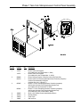
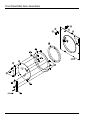
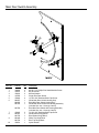
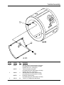
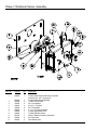
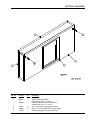
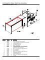
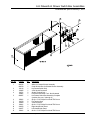
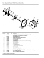
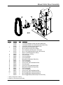
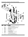
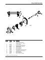
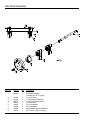
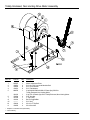
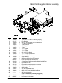
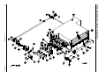
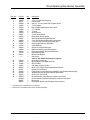
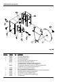
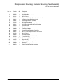
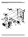
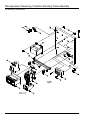
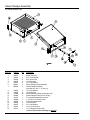
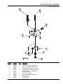
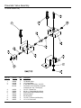
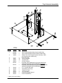
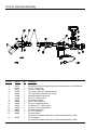
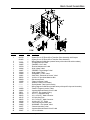
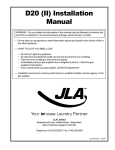
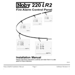
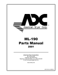
D170 Parts Manual
Phase 7
JLA Limited
Meadowcroft Lane, Halifax Road
Ripponden
West Yorkshire, England
HX6 4AJ
Telephone: 01422 822282 / Fax: 01422 824390
JLA Part No. 450597
Retain This Manual in a Safe Place for Future Reference
This product embodies advanced concepts in engineering, design, and safety. If this product is properly
maintained, it will provide many years of safe, efficient, and trouble free operation.
Only qualified technicians should service this equipment.
OBSERVE ALL SAFETY PRECAUTIONS displayed on the equipment or specified in the installation
manual included with the dryer.
The following “FOR YOUR SAFETY” caution must be posted near the dryer in a prominent location.
FOR YOUR SAFETY
POUR VOTRE SÉCURITÉ
Do not store or use gasoline
or other flammable vapors
and liquids in the vicinity of
this or any other appliance.
Ne pas entreposer ni utiliser d’essence
ni d’autres vapeurs ou liquides
inflammables à proximité de cet
appareil ou de tout autre appareil.
We have tried to make this manual as complete as possible and hope you will find it useful. The
manufacturer reserves the right to make changes from time to time, without notice or obligation, in prices,
specifications, colors, and material, and to change or discontinue models. The illustrations included in
this manual may not depict your particular dryer exactly.
IMPORTANT
For your convenience, log the following information:
D170
DATE OF PURCHASE _____________________________________________________________MODEL NO. ________________________
RESELLER’S NAME _________________________________________________________________________________________________
Serial Number(s) __________________________________________________________________________________________________
___________________________________________________________________________________________________________________
___________________________________________________________________________________________________________________
Replacement parts can be obtained from your reseller or JLA. When ordering replacement parts from the
factory, you can FAX your order to JLA at 1 422-824390 or telephone your order directly to the JLA Parts
Department at 1 422-822282. Please specify the dryer model number and serial number in addition to the
description and part number, so that your order is processed accurately and promptly.
“IMPORTANT NOTE TO PURCHASER”
Information must be obtained from your local gas supplier on the
instructions to be followed if the user smells gas. These instructions
must be posted in a prominent location near the dryer.
Table of Contents
Control Door Assembly .................................................................................................................................... 4
Phase 7 Non-Coin Microprocessor Control Panel Assembly ....................................................................... 5
Front Panel/Main Door Assemblies ............................................................................................................ 6, 7
Main Door Switch Assembly ............................................................................................................................ 8
Tumbler Assembly ............................................................................................................................................ 9
Phase 7 Rotational Sensor Assembly .......................................................................................................... 10
Lint Door Assembly ........................................................................................................................................ 11
Lint Drawer/Lint Drawer Switch Box Assemblies for Models Mfd. as of February 1, 2003 ...................... 12
Lint Drawer/Lint Drawer Switch Box Assemblies for Models Mfd. prior to February 1, 2003 .................. 13
Fan (Squirrel Cage) Shaft Mount Assembly ................................................................................................. 14
Blower Motor Mount Assembly ...................................................................................................................... 15
Microprocessor Temperature Sensor Bracket Assembly ........................................................................... 16
Drive Shaft Assembly ..................................................................................................................................... 17
Idler Shaft Assembly ...................................................................................................................................... 18
Speed Reducer Shaft Assembly ................................................................................................................... 19
Totally Enclosed, Non-Venting Drive Motor Assembly ................................................................................. 20
CE Hot Surface Ignition Burner Assembly ................................................................................................... 21
Direct Spark Ignition Burner Assembly ................................................................................................... 22, 23
Sail Switch Assembly ..................................................................................................................................... 24
Air Jet Assembly ............................................................................................................................................. 25
Microprocessor Reversing Contactor Mounting Panel Assembly for 208-240V Transformers ......... 26, 27
Microprocessor Reversing Contactor Mounting Panel Assembly for 380-416V Transformers ......... 28, 29
Microprocessor Reversing Contactor Mounting Panel Assembly for 460-480V Transformers ......... 30, 31
Steam Damper Assembly for Steam Models Only ...................................................................................... 32
Pneumatic Valve Assembly for Gas Models Only ........................................................................................ 33
Pneumatic Valve Assembly for Steam Models Only .................................................................................... 34
Top Console Assembly .................................................................................................................................. 35
S.A.F.E. Temperature Probe Assembly ........................................................................................................ 36
S.A.F.E. Solenoid Assembly for Models Mfd. as of September 23, 2004 .................................................. 37
S.A.F.E. Solenoid Assembly .......................................................................................................................... 38
Back Guard Assemblies ................................................................................................................................ 39
Control Door Assembly
Illus. No.
Part No.
Qty.
1*
883256
883322
150314
154011
———
1
1
4
4
1
2
3
4**
Description
Phase 7 Control Door (gas)
Phase 7 Control Door (steam)
#10-32 x 1/2” TORX Screw
#10-32 Multi-Thread U-Nut
Logo
* Specify color when ordering.
** Contact reseller for logo.
4
JLA Limited
450597-2
Phase 7 Non-Coin Microprocessor Control Panel Assembly
Illus. No.
Part No.
Qty.
1
112577
1
112571
1
2
850980
822754
1
1
3
887005
1
887002
1
150005
153010
136016
136097
2
2
1
1
4
5
6
7
450597-2
Description
Phase 7 Non-Coin Keypad
(for models mfd. as of September 11, 2004)
Phase 7 Non-Coin Keypad
(for models mfd. prior to September 11, 2004)
Phase 7 Microprocessor Controller (computer) Panel Only
Phase 7 Non-Coin Reversing Microprocessor Controller (computer)
Control Panel Assembly Complete
(includes illus. nos. 1 through 7)
Phase 7.2.2 Non-Coin Microprocessor Controller (computer)
with Sensor Activated Fire Extinguishing System Only
(for models mfd. as of December 3, 2003)
Phase 7.2.1 Non-Coin Microprocessor Controller (computer)
with Sensor Activated Fire Extinguishing System Only
(for models mfd. prior to December 3, 2003)
#6-32 x 3/4” Phillips Round Head Machine Screw
#6 Star Washer
5 amp Fuse
500 mA Fuse
Telephone: 01422 822282 / Fax: 01422 824390
5
Front Panel/Main Door Assemblies
6
JLA Limited
450597-2
Front Panel/Main Door Assemblies
Illus. No.
Part No.
Qty.
1
7
881685
882296
881740
881739
151012
881688
881737
102214
170730
881806
882293
150120
1
1
6
6
1
1
1
1
1
6
6
1
8
9
151010
881689
1
1
881761
1
881966
882305
882411
882503
1
1
1
1
882504
1
170330
154215
122351
122419
132387
132395
1
2
1
1
1
1
2
3
4
5
6
10
11
12
13
14
15
16
17
450597-2
Description
White Main Door Hinge
Coral Wrinkle Blue Main Door Hinge
1/4-20 x 5/8” White Carriage Bolt
1/4-20 x 5/8” Coral Wrinkle Blue Carriage Bolt
#10-32 White Acorn Nut
White Main Door Handle
Blue Main Door Handle
30” Door Glass
Door Glass Adhesive (10.3 oz. cartridge)
1/4-20 White Free Spin Wash Nut
1/4-20 Coral Wrinkle Blue Free Spin Wash Nut
Main Door Latch Screw
(#10-32 dome hex head screw)
#10-32 Acorn Nut
White Main Door Assembly Complete
(includes illus. nos. 2 through 10)
Coral Wrinkle Blue Main Door Assembly Complete
(includes illus. nos. 2 through 10)
White Main Door Ring
Coral Wrinkle Blue Cold Rolled Steel Large Main Door Ring
Extruded Steel Door Gasket
White Front Panel Assembly
(includes illus. nos. 1, 15, and 16)
Coral Wrinkle Blue Front Panel Assembly
(includes illus. nos. 1, 15, and 16)
Friction Door Latch
5/32” Pop Rivet
“EMERGENCY STOP” Push-Pull Button
“EMERGENCY STOP” Nameplate
Normally Closed Contact Block
Normally Closed Contact Block with Base
Telephone: 01422 822282 / Fax: 01422 824390
7
Main Door Switch Assembly
Illus. No.
Part No.
Qty.
1
2
3
4
5
6
150006
152013
153010
137005
150443
881687
881695
881702
2
2
2
1
4
1
1
1
881700
1
150443
881441
881735
881440
881736
153031
2
1
1
1
1
1
7
8
9
10
8
Description
#6-32 x 7/8” Phillips Pan Head Machine Screw
#6-32 Hex Nut
#6 Star Washer
Single-Pole Door Switch
1/4-20 x 3/4” Stainless Steel Cap Screw
White Main Door Switch Housing Only
Blue Main Door Switch Housing Only
White Main Door Switch with Housing Assembly
(includes illus. nos. 1 through 4 and 6)
Blue Main Door Switch with Housing Assembly
(includes illus. nos. 1 through 4 and 6)
1/4-20 x 3/4” Stainless Steel Cap Screw
White Bottom Hinge Block
Blue Bottom Hinge Block
White Top Hinge Block
Blue Top Hinge Block
Nylon Washer
JLA Limited
450597-2
Tumbler Assembly
Illus. No.
Part No.
Qty.
1
835402
1
835375
1
390329
4
883578
4
150118
24
2
3
450597-2
Description
Stainless Steel Tumbler Assembly Complete
(for models mfd. as of November 10, 2003)
(includes illus. nos. 1 through 3)
Tumbler Assembly Complete
(for models mfd. prior to November 10, 2003)
(includes illus. nos. 1 through 3)
Stainless Steel Perforated Tumbler Panel
(for models mfd. as of November 10, 2003)
Perforated Tumbler Panel
(for models mfd. prior to November 10, 2003)
1/4-20 x 1/4” Phillips Pan Head Screw
Telephone: 01422 822282 / Fax: 01422 824390
9
Phase 7 Rotational Sensor Assembly
Illus. No.
Part No.
Qty.
1
819064
1
2
3
4
5
6
7
8
9
10
11
835339
102394
153005
150619
153004
180018
819046
819065
822735
152005
323433
1
2
6
2
8
2
1
1
1
4
2
10
Description
Tumbler Shaft Support Assembly Complete
(includes illus. nos. 1 through 8)
Tumbler Shaft Support Bracket
Tumbler Friction Pad
3/8” Lock Washer
3/8-16 x 1” Tap Bolt
3/8” Flat Washer
4” x 1-1/2” Hi-Impact Wheel
Tumbler Adjustment Plate
Tumbler Shoulder Screw
Phase 7 Rotational Sensor Assembly
3/8-16 Hex Nut
Rear Wheel Shim
JLA Limited
450597-2
Lint Door Assembly
Illus. No.
Part No.
Qty.
1
882497
1
882498
1
117607
150309
117604
6
5
9
2
3
4
450597-2
Description
White Lint Door Assembly
(includes illus. nos. 1, 2, and 4)
Coral Wrinkle Blue Lint Door Assembly
(includes illus. nos. 1, 2, and 4)
1/4” x 3/8” Poron Foam (sold by the foot)
#10-16 x 1/2” Hex Head TEK Crimptite Screw
Neoprene Sponge Tape (sold by the foot)
Telephone: 01422 822282 / Fax: 01422 824390
11
Lint Drawer/Lint Drawer Switch Box Assemblies
For Models Mfd. as of February 1, 2003
Illus. No.
Part No.
Qty.
1
5
884069
884068
122116
122605
122701
122801
882507
1
1
1
1
2
1
1
6
7
8
9
10
11
12
13
150301
122700
122604
150301
319076
319077
150301
108220
4
2
1
2
1
1
14
1
2
3
4
12
Description
White Lint Drawer/Screen Assembly
Coral Wrinkle Blue Lint Drawer/Screen Assembly
Lint Drawer Switch Only
4-Pin Socket Connector
Socket Terminal Only
Pin/Socket Extraction Tool...Not Illustrated
Lint Drawer Switch Box Assembly Complete
(includes illus. nos. 3 through 6)
#8-18 x 7/16” Phillips Pan Head TEK Screw
Pin Terminal Only
4-Pin Connector
#8-18 x 7/16” Phillips Pan Head TEK Screw
Right Hand Divider Panel
Left Hand Divider Panel
#8-18 x 7/16” Phillips Pan Head TEK Screw
Lint Bag
JLA Limited
450597-2
Lint Drawer/Lint Drawer Switch Box Assemblies
For Models Mfd. prior to February 1, 2003
Illus. No.
Part No.
Qty.
1
5
882792
882793
122116
122605
122701
122801
882507
1
1
1
1
2
1
1
6
7
8
9
10
11
12
150301
122700
122604
150301
319076
319077
150301
4
2
1
2
1
1
14
2
3
4
450597-2
Description
White Lint Drawer/Screen Assembly
Coral Wrinkle Blue Lint Drawer/Screen Assembly
Lint Drawer Switch Only
4-Pin Socket Connector
Socket Terminal Only
Pin/Socket Extraction Tool...Not Illustrated
Lint Drawer Switch Box Assembly Complete
(includes illus. nos. 3 through 6)
#8-18 x 7/16” Phillips Pan Head TEK Screw
Pin Terminal Only
4-Pin Connector
#8-18 x 7/16” Phillips Pan Head TEK Screw
Right Hand Divider Panel
Left Hand Divider Panel
#8-18 x 7/16” Phillips Pan Head TEK Screw
Telephone: 01422 822282 / Fax: 01422 824390
13
Fan (Squirrel Cage) Shaft Mount Assembly
Illus. No.
Part No.
Qty.
1
2
100612
821078
1
1
3
4
5
6
7
8
9
10
11
12
13
14
15
16
17*
18
19
821073
117604
152006
153065
332280
881061
153004
153005
152005
100812
880879
153004
153005
150617
101177
100184
100706
101194
1
4’
2
1
1
1
4
4
4
2
1
2
2
2
1
2
1
1
*
14
Description
1-1/4” Bore x 15” Diameter x 6” Blower/Fan (squirrel cage)
Fan Shaft Mount Assembly Complete
(includes illus. nos. 1 through 16, 18, and 19)
Fan Shaft Mount Only
Neoprene Sponge Tape (sold by the foot)
1/2-20 Left Hand Jam Nut
1/2” Flat Washer
Fan Shaft Only
1-3/8” Flange Bearing with Setscrews and Grease Fitting
3/8” Flat Washer
3/8” Lock Washer
3/8-16 Hex Nut
1-3/8” Retaining Ring
1-3/8” Pillow Block Bearing Only
3/8” Flat Washer
3/8” Lock Washer
3/8-16 x 1” Hex Head Bolt
2B x 5.8 Pulley (for gas models Only)
BX-63 Cogged Belt (fan shaft to blower motor) for 60 Hz Models Only
5/16” x 5/16” x 1-3/8” Key
SDS x 1-3/8” Bushing with Setscrew
Replace in matched sets (both belts).
JLA Limited
450597-2
Blower Motor Mount Assembly
Illus. No.
Part No.
Qty.
1
181030*
181031*
181039
101148
101147
101195
101152
101194
100706
152004
153002
153001
821091
153001
153002
150501
152004
150503
332322
153001
153002
150501
100184
100195
100159
1
1
1
1
1
1
1
1
1
4
4
4
1
4
4
4
4
2
1
2
2
2
2
2
2
2
3
4
5
6
7
8
9
10
11
12
13
14
15
16
17
18**
**
**
Description
7.5 hp 208-230/460v 3-Phase (3ø) 60 Hz Motor Only
7.5 hp 200-230/380-410v 3-Phase (3ø) 50 Hz Motor Only
7.5 hp 575v 3-Phase (3ø) 60 Hz Motor Only
SB x 4.0 Motor Pulley (60 Hz gas)
SB x 4.8 Motor Pulley (50 Hz steam)
2B x 4.4 Sheave (60 Hz steam / 50 Hz gas)
SH x 1-3/8” Bushing (50/60 Hz gas / 60 Hz steam)
SDS x 1-3/8” Bushing (50 Hz steam)
5/16” x 5/16” x 1-3/8” Key
5/16-18 Hex Nut
5/16” Lock Washer
5/16” Flat Washer
Motor Mount Adjustment Plate Only
5/16” Flat Washer
5/16” Lock Washer
5/16-18 x 3/4” Hex Head Machine Bolt
5/16-18 Hex Nut
5/16-18 x 2” Hex Head Machine Bolt
Motor Mount Adjustment Angle Only
5/16” Flat Washer
5/16” Lock Washer
5/16-18 x 3/4” Hex Head Machine Bolt
BX-63 Cogged Belt (matched sets) 60 Hz
BX-73 Cogged Belt (matched sets) 50 Hz
BX-61 Cogged Belt (matched sets) 575v 60 Hz Only
* Specify voltage when ordering.
** Replace in matched sets (both belts).
450597-2
Telephone: 01422 822282 / Fax: 01422 824390
15
Microprocessor Temperature Sensor Bracket Assembly
Illus. No.
Part No.
Qty.
1
815931
1
8
9
10
820967
150005
153010
130103
152000
121028
122701
122801
122605
154007
815961
1
2
2
1
2
2
4
1
1
2
1
11
150301
4
2
3
4
5
6
7
16
Description
Microprocessor Temperature Sensor Bracket Complete
(includes illus. nos. 1 through 10)
Microprocessor Temperature Sensor Bracket Only
#6-32 x 1/4” Phillips Round Head Machine Screw
#6 Star Washer
225° Manual Reset Thermostat Only
#6-32 Hex Nut
1/4” x .032 Insulated Terminal
Socket Terminal Only
Pin/Socket Extraction Tool...Not Illustrated
4-Pin Socket Connector
1/4” Push On Fastener
1/4” Temperature Sensor Probe Assembly
(includes illus. nos. 6 through 10)
#8-18 x 7/16” Phillips Pan Head TEK Screw
JLA Limited
450597-2
Drive Shaft Assembly
Illus. No.
Part No.
Qty.
1
882460
1
2
3
4
5
6
7
8
9
10
11*
12
821465
101234
880779
152011
153005
153004
835360
101184
101189
100140
100717
1
1
2
4
4
4
2
1
1
2
1
*
Description
Tumbler Shaft Assembly
(includes illus. nos. 1 and 4)
11” Drive Wheel
Drive with Hub Taper Bushing
1-3/8” Pillow Block Bearing
3/8-18 Hex Nut
3/8” Lock Washer
3/8” Flat Washer
Bearing Backing Plate Assembly
1-3/8” Bushing with Setscrew
2B x 8.0 Pulley
BX-38 Cogged Belt
5/16” x 5/16” x 2-3/4” Key
Replace in matched sets (both belts).
450597-2
Telephone: 01422 822282 / Fax: 01422 824390
17
Idler Shaft Assembly
Illus. No.
Part No.
Qty.
1
882460
1
2
3
4
5
6
7
8
9
821465
101234
880779
152011
153005
153004
835360
100717
1
1
2
4
4
4
2
1
18
Description
Idler Shaft Assembly
(includes illus. nos. 1 and 4)
11” Drive Wheel
1-3/8” Taper Lock Bushing
1-3/8” Pillow Block Bearing
3/8-18 Hex Nut
3/8” Lock Washer
3/8” Flat Washer
Bearing Backing Plate Assembly
5/16” x 5/16” x 2-3/4” Long Key
JLA Limited
450597-2
Speed Reducer Shaft Assembly
Illus. No.
Part No.
Qty.
1
882505
1
2
101160
1
101187
1
3
4
5
6
7
8
9
10
11*
12*
13
101150
880779
152005
153005
153004
835361
100717
101193
100124
100140
101152
1
2
4
4
4
2
1
1
2
2
1
14
100717
1
*
Description
Speed Reducing Shaft Assembly
(includes illus. nos. 1, 3, 4, and 10)
2B x 3.4 SH Sheave
(for models mfd. as of March 6, 2000)
2B x 4.0” Pulley
(for models mfd. prior to March 6, 2000)
1-3/8” Bushing with Setscrew
1-3/8” Pillow Block Bearing
3/8-16 Hex Nut
3/8” Lock Washer
3/8” Flat Washer
Bearing Back Up Plate
5/16” x 5/16” x 2-3/4” Long Key
2B x 13.6” SK Sheave
BX-53 Belt
BX-38 Cogged Belt
SH x 1-3/8” Bushing (60 Hz)
(includes illus. no. 9)
5/16” x 5/16” x 2-3/4” Key
Replace in matched sets (both belts).
450597-2
Telephone: 01422 822282 / Fax: 01422 824390
19
Totally Enclosed, Non-Venting Drive Motor Assembly
Illus. No.
Part No.
Qty.
1
2
3
4
5
835297
150501
153002
153001
882078
1
4
8
8
1
6
7
8*
9**
10
11
181019
152004
101235
100124
———
150619
152005
1
4
1
2
1
2
4
Description
Motor Adjustment Plate
5/16-18 x 3/4” Hex Head Machine Bolt
5/16” Lock Washer
5/16” Flat Washer
3 hp 208-230/380/416/460v 3-Phase (3ø) 50/60 Hz
Totally Enclosed, Non-Venting Motor
3 hp 575v 3-Phase (3ø) 60 Hz Totally Enclosed, Non-Venting Motor
5/16” Hex Nut
1-1/8” Pulley
BX-53 Cogged Belt
5/16” Key
3/8-16 x 3” Tap Bolt
3/8-16 Hex Nut
* Replace in matched sets (both belts).
** Consult factory.
20
JLA Limited
450597-2
CE Hot Surface Ignition Burner Assembly
Illus. No.
Part No.
Qty.
1
2
3
4
5
6
7
8
9
10
11
12
13
14
15
16
17
18
19
20
21
22
23
24
25
142938
332117
150309
142817
141302
142724
142602
142581
142548
142581
332487
140028
332486
141240
140839
140820
883331
390169
141136
332121
390170
128975
151000
130201
151001
820987
———
1
1
25
1
1
1
1
1
1
1
1
1
1
1
4
4
1
1
4
1
1
1
2
1
2
1
1
26
27
128921
881597
1
1
450597-2
Description
1-1/2” B.S.P.T. x 1” N.P.T. Reducing Coupling
Pipe Bracket
#10-16 x 1/2” Hex Head TEK Crimptite Screw
1” x 28-1/2” Black Nipple
1” Union Shutoff
1” x 2” Nipple
1” Union
1” x 5” Nipple
1” x 90º Elbow
1” x 5” Nipple
Gas Valve Pipe Bracket
1” x 1” 24 VAC CE Gas Valve
Gas Valve Pipe Bracket
4-Port Manifold
#2 Burner Orifice (natural gas)
#29 Burner Orifice (liquid propane gas)
D170 Liquid Propane Conversion Kit
4 Tube Burner Hot Surface Ignition Mount Manifold Rest
Uginox Burner Tube
Burner Tube Support
Hot Surface Ignition Burner Box Cover Plate
CE Hot Surface Ignition Module
#6-32 Pal Nut
330º Hi-Limit Manual Reset
#6-32 x 1/2” Round Head Machine Screw
Burner Box
Sail Switch Assembly
(refer to Sail Switch Assembly on page 24)
Hot Surface Ignition Flame Sensor
Hot Surface Ignition Ignitor
Telephone: 01422 822282 / Fax: 01422 824390
21
JLA Limited
Direct Spark Ignition Burner Assembly
22
450597-2
Direct Spark Ignition Burner Assembly
Illus. No.
Part No.
Qty.
1
2
3
4
5
6
7
8
9
10
11
12
142929
332117
150309
142583
128919
142808
142602
152013
142507
128915
332487
140028
882945
332486
141240
140839
140820
390169
141136
332121
———
1
1
33
1
1*
1
1
2
1
1
1
1
1
1
1
4
4
1
4
1
1
332113
331290
151000
130201
150005
821457
332256
801048
153562
835037**
821960**
820987
880743
1
1
2
1
2
1
1
1
2
1
1
1
1
13
14
15*
16
17
18
19
20
21
22
23
24
25
26
27
28
29
Description
1-1/2” x 1” Reducing Coupling
Pipe Bracket
#10-16 x 1/2” Hex Head TEK Crimptite Screw
1” x 40” Nipple
High Voltage Ignition Cable with Cap 36”
1” x 3” Nipple
1” Union
#6-32 Hex Nut
1” x 90º Street Elbow
Direct Spark Ignition Ignitor
Gas Pipe Bracket Straight Extended
1” 24 VAC Redundant Gas Valve (natural gas)
1” 24 VAC Gas Valve (liquid propane gas)
Gas Pipe Bracket Bent Extended
4-Port Manifold
#2 Burner Orifice (natural gas)
#29 Burner Orifice (liquid propane gas)
Direct Spark Ignition Mount Manifold Rest
Uginox Burner Tube
Burner Tube Support
Sail Switch
(refer to Sail Switch Assembly on page 24)
Burner Box Cover Plate
Ignitor/Flame-Probe Sight Hole Disc
#6-32 Pal Nut
330º Manual Reset Hi-Limit
#6-32 x 1/4” Phillips Round Head Machine Screw
Burner Hi-Limit Bracket
Large Dryer Liquid Propane Burner Baffle (Liquid Propane Models Only)
Johnson Direct Spark Ignition Module (three tries)
#6-32 x 3/4” Clinch Stud
Burner Assembly (natural gas) Complete Less Orifice
Burner Assembly (liquid propane gas) Complete Less Orifice
Burner Box
Direct Spark Ignition Liquid Propane Conversion Kit
* Consult factory for elevations over 2,000 feet.
** Orifices are not included and must be ordered separately.
450597-2
Telephone: 01422 822282 / Fax: 01422 824390
23
Sail Switch Assembly
Illus. No.
Part No.
Qty.
1
2
3
4
105500
319202
154002
802800
802801
1
1
1
1
1
882010
1
150300
150303
122200
122404
802799
150309
154004
2
2
1
1
1
2
1
5
6
7
8
9
10
24
Description
Sail Switch Actuator Rod
Sail Switch Damper (flat)
1/8” Push On Fastener
Sail Switch Box with Cover and Bracket Only
Sail Switch Box Assembly Complete
for Microprocessor Controller (computer) Models Only
(includes illus. nos. 1 through 4 and 6 through 10)
Sail Switch Box Assembly Complete for Dual Timer Models Only
(includes illus. nos. 1 through 4 and 6 through 10)
#10-16 x 1/2” Hex Washer TEK Screw
#4 x 3/4” Pan Head “A” Machine Screw
Sail Switch Only (for microprocessor controller [computer] models Only)
Sail Switch Only (for dual timer models Only)
Sail Switch Box Cover and Bracket Only
#10-16 x 1/2” Hex Head TEK Crimptite Screw
Twin Speed Nut
JLA Limited
450597-2
Air Jet Assembly
Illus. No.
Part No.
Qty.
Description
1
2
3
4
332700
143287
143259
143100
821081
1
1
2
36”
1
5
6
7
8
9
332531
152002
153007
143115
143149
1
2
2
6’
1
Air Jet Tube Only
1/4” x 1/8” M.P.T. Male Run Tee
1/4” x 1/8” F.P.T. Bulkhead Fitting
1/4” Aluminum Tube (sold by the inch)
Air Jet Assembly
(includes illus. nos. 1 through 9)
Air Jet Mounting Plate Only
1/4-20 Hex Nut
1/4” Lock Washer
1/4” Poly-Flo Tubing (sold by the foot)
1/4” x 1/8” M.P.T. 90° Elbow
450597-2
Telephone: 01422 822282 / Fax: 01422 824390
25
Microprocessor Reversing Contactor Mounting Panel Assembly
For 208-240V Transformers
26
JLA Limited
450597-2
Microprocessor Reversing Contactor Mounting Panel Assembly
For 208-240V Transformers
Illus. No.
Part No.
Qty.
1
2
3
4
5
6
7
8
9
10
11
12
13
14
15
16
17
18
19
20
21
22
23
—
—
152002
132465
151001
150009
120701
132497
822745
137015
153021
152004
153002
136008
136057
332346
150301
151000
120765
150108
121010
120768
112075
112068
132439
825267
829053
1
1
2
2
1
1
1
1
1
1
1
2
2
1
5
2
2
2
2
7-3/4”
1
1
1
1
1
450597-2
Description
1/4-20 Hex Nut
3 hp Contactor – 24 VAC
#8-32 Pal Nut
#6-32 x 1-1/4” Phillips Round Head Machine Screw
4-Position Power Distribution Block
Reversing Contactor – 24 VAC
208-240V Transformer Assembly
Arc Suppressor Board
1/4” Exterior/Interior Shake Proof Washer
5/16-18 Hex Nut
5/16” Lock Washer
Fuse Block/Holder
1/2 amp (Slo-Blo) Fuse
Contactor/Relay Mounting Panel Only
#8-18 x 7/16” Phillips Pan Head TEK Screw
#6-32 Pal Nut
End Stop/Bracket
#8-32 x 1/2” Pan Head Machine Screw
L-70 Ground Lug
Din Mounting Rail (sold by the inch)
Ground Label
3-Phase (3ø) Power Input Label
Overload
Contactor Wiring...Not Illustrated
Relay Panel Wiring...Not Illustrated
Telephone: 01422 822282 / Fax: 01422 824390
27
Microprocessor Reversing Contactor Mounting Panel Assembly
For 380-416V Transformers
28
JLA Limited
450597-2
Microprocessor Reversing Contactor Mounting Panel Assembly
For 380-416V Transformers
Illus. No.
Part No.
Qty.
1
2
3
4
5
6
7
8
9
10
11
12
13
14
15
16
17
18
19
20
—
—
132467
132465
151001
150009
120701
132497
801580
152004
121012
153002
136008
136057
332346
150301
151000
120765
150108
150297
121010
120768
830180
825267
1
1
2
2
1
1
1
2
1
2
1
1
1
4
2
2
2
1
1
7-3/4”
1
1
450597-2
Description
9-13 amp Overload
10 hp Contactor – 24 VAC
#8-32 Pal Nut
#6-32 x 1-1/2” Phillips Round Head Machine Screw
4-Position Power Distribution Block
“Kline” Reversing Contactor
Transformer (380-416 Volt / 3-Phase [3ø])
5/16-18 Hex Nut
Ground Lug
5/16” Lock Washer
Fuse Block/Holder
1/2 amp (Slo-Blo) Fuse
Contactor/Relay Mounting Panel Only
#8-18 x 7/16” Phillips Pan Head TEK Screw
#6-32 Pal Nut
End Stop/Bracket
#8-32 x 1/2” Pan Head Machine Screw
#10 x 1/2” Hex Washer TEK Screw
L-70 Ground Lug
Din Mounting Rail (sold by the inch)
Relay Panel Wiring...Not Illustrated
Drive/Blower Motor Contactor Wiring...Not Illustrated
Telephone: 01422 822282 / Fax: 01422 824390
29
Microprocessor Reversing Contactor Mounting Panel Assembly
For 460-480V Transformers
30
JLA Limited
450597-2
Microprocessor Reversing Contactor Mounting Panel Assembly
For 460-480V Transformers
Illus. No.
Part No.
Qty.
1
2
3
4
5
6
7
8
9
10
11
12
13
14
15
16
17
18
19
20
—
—
132467
132465
151001
150009
120701
132497
830193
152004
121012
153002
135501
137015
332346
150301
151000
120765
150108
150297
121010
120768
830192
825267
1
1
2
2
1
1
1
2
1
2
1
1
1
4
2
2
2
1
1
7-3/4”
1
1
450597-2
Description
9-13 amp Overload
10 hp Contactor – 24 VAC
#8-32 Pal Nut
#6-32 x 1-1/2” Phillips Round Head Machine Screw
4-Position Terminal Block
“Kline” Reversing Contactor
460-480V Transformer Assembly
5/16-18 Hex Nut
Ground Lug
5/16” Lock Washer
2-Pole 1 amp Circuit Breaker
Arc Suppressor
Relay Panel
#8-18 x 7/16” Phillips Pan Head TEK Screw
#6-32 Pal Nut
End Stop/Bracket
#8-32 x 1/2” Pan Head Machine Screw
#10 x 1/2” Hex Washer TEK Screw
L-70 Ground Lug
Din Mounting Rail (sold by the inch)
Relay Panel Wiring...Not Illustrated
Drive/Blower Motor Contactor Wiring...Not Illustrated
Telephone: 01422 822282 / Fax: 01422 824390
31
Steam Damper Assembly
For Steam Models Only
Illus. No.
Part No.
Qty.
1
2
3
4
5
6
7
165017
153002
152004
152002
153007
820321
820994
1
6
6
4
4
2
1
8
9
10
11
12
13
14
15
16
17
18
153007
152002
115995
102350
151007
100499
100500
152002
153007
100472
143115
4
4
96”
2
1
1
1
4
4
1
1
32
Description
Steam Coil Only
5/16” Lock Washer
5/16-18 Hex Nut
1/4-20 Hex Nut
1/4” Lock Washer
Steam Damper Hinge Assembly
Steam Damper Assembly
(includes illus. nos. 7, 10, and 11)
1/4” Lock Washer
1/4-20 Hex Nut
Steam Damper Gasket (sold by the inch)
Steam Damper Foam (68-1/2” length)
7/16-20 Stainless Steel Acorn Nut
1-1/2” Bore x 3” Stroke Piston
Piston Support Bracket
1/4-20 Hex Nut
1/4” Lock Washer
1/4” x 1/8” Connector
1/4” Tubing (sold by the foot)
(refer to Top Console Assembly on page 35)
JLA Limited
450597-2
Pneumatic Valve Assembly
For Gas Models Only
Illus. No.
Part No.
Qty.
1
2
3
100520
150002
100498
821105
1
1
1
1
4
5
6
7
8
143268
100472
330987
153010
152000
1
1
1
1
1
450597-2
Description
1/8” N.P.T. Silencer (muffler) Only
#6-32 x 1” Slotted Machine Screw
3-Way Micro Valve Only – 24 VAC
Pneumatic Valve Assembly Complete
(includes illus. nos. 1 through 8)
1/8” Street Elbow
1/4” x 1/8” Connector
Micro Valve Support Bracket Only
#6 Star Washer
#6-32 Hex Nut
Telephone: 01422 822282 / Fax: 01422 824390
33
Pneumatic Valve Assembly
For Steam Models Only
Illus. No.
Part No.
Qty.
1
2
3
100496
143238
100498
821104
1
3
2
1
4
5
6
7
8
9
10
143223
150002
330987
153010
152000
100520
100472
1
2
1
2
2
2
2
34
Description
1/8” Needle Valve
1/8” Close Nipple
3-Way Micro Valve Only – 24 VAC
Pneumatic Valve Assembly Complete
(includes illus. nos. 1 through 8)
1/8” F.P.T. Brass Tee
#6-32 x 1” Slotted Machine Screw
Micro Valve Support Bracket Only
#6 Star Washer
#6-32 Hex Nut
1/8” N.P.T. Silencer (muffler) Only
1/4” x 1/8” Connector
JLA Limited
450597-2
Top Console Assembly
Illus. No.
Part No.
Qty.
1
2
821085*
821086*
114508
1
1
1
3
4
5
6
7
———
153007
152002
332323
821105
1
12
12
1
1
821104
1
121104
121105
150615
153018
332186
332132
1
1
1
4
1
1
8
9
10
11
12
13
*
Description
Top Console Assembly Only (for gas models Only)
Top Console Assembly Only (for steam models Only)
“Phase 7 Non-Coin Program Location Summary” Label
(for microprocessor models Only)
Dryer Data Label
1/4” Lock Washer
1/4-20 Hex Nut
32” Wire Channel
Pneumatic Valve Assembly Only (for gas models Only)
(refer to Pneumatic Valve Assembly on page 33)
Pneumatic Valve Assembly Only (for steam models Only)
(refer to Pneumatic Valve Assembly on page 34)
2” x 4” Junction Box Only
Junction Box Cover Only
1/4-20 x 3/4” Bolt
1/4” Flat Washer
Control Door Hinge Channel
Corner Gusset Brace
Specify color when ordering.
450597-2
Telephone: 01422 822282 / Fax: 01422 824390
35
S.A.F.E. Temperature Probe Assembly
Illus. No.
Part No.
Qty.
1
822752
1
2
3
4
154007
390390
150301
122647
2
1
2
1
5
122700
2
36
Description
Sensor Activated Fire Extinguishing System Temperature Probe Assembly
(includes illus. nos. 1 through 5)
Push On Fastener
Sensor Bracket Only
#8-18 Phillips Pan Head TEK Screw
Connector Only...Not Illustrated
(does not include pins)
Pins
JLA Limited
450597-2
S.A.F.E. Solenoid Assembly
For Models Mfd. as of September 23, 2004
Illus. No.
Part No.
Qty.
1
2
3
4
5
6
7
8
9
10
11
12
13
14
15
16
17
18
143581
143303
136987
143251
182579
143220
143301
311588
143208
311587
143108
154338
150309
152001
142887
143182
165119
143183
1
1
1
1
1
1
1
1
2
1
1
2
2
2
1
1
1
1
450597-2
Description
3 GPM 3/8” F.P.T. Spray Nozzle
3/8” N.P.T. Brass Locknut
Pressure Switch
3/8” M.P.T. Brass Plug
3/8” Hex Nipple
3/8” F.P.T. Brass Tee
3/8” Brass 45° Elbow
Sprinkler Head Mounting Plate
3/8” Comp x 3/8” M.P.T. Brass Connector
Valve Bracket
20” Long Stainless Steel Flexible Tubing
Machine Screw
#10-16 x 1/2” Hex Head TEK Crimptite Screw
#8-32 x 3/8” OD Hex Nut
Bushing
3/4” x 1/8” x 3/8” N.P.T. Brass Tee
Water Inlet Valve
7/16-20 x 3/8” N.P.T. Brass Adaptor
Telephone: 01422 822282 / Fax: 01422 824390
37
S.A.F.E. Solenoid Assembly
Illus. No.
Part No.
Qty.
1
2
3
4
5
6
7
8
9
10
11
12
13
14
15
165114
143220
143251
143208
143108
311588
143303
143301
152001
150430
143581
143025
824081
143315
136987
1
2
1
2
1
1
1
1
2
2
1
1
1
1
1
16
182579
1
38
Description
Sensor Activated Fire Extinguishing System Solenoid Valve 24 VAC 50/60 Hz
3/8” F.P.T. Brass Tee
3/8” M.P.T. Brass Plug
3/8” Comp x 3/8” M.P.T. Brass Connector
20” Long Stainless Steel Flexible Tubing
Sprinkler Head Mounting Plate
3/8” N.P.T. Brass Locknut
3/8” Brass 45° Elbow
#8-32 x 3/8” OD Hex Nut
#10 x 1/2” Self Drilling Screw
3 GPM 3/8” F.P.T. Spray Nozzle
3/8” N.P.T. Nylon Hose Adaptor
RC Network Assembly
3/8” x 1/8” Bushing
Pressure Switch
(for models mfd. between December 3, 2003 and September 22, 2004)
3/8” Hex Nipple
(for models mfd. between December 3, 2003 and September 22, 2004)
JLA Limited
450597-2
Back Guard Assemblies
Illus. No.
Part No.
Qty.
1
821793
821956
———
112046
114005
112519
114044
114007
112014
114008
114001
150512
332309
112280
112017
———
———
114508
114093
170511
143164
100472
143115
100472
143246
114095
114006
114077
114093
153007
1
1
1
1
1
1
1
1
1
1
1
4
1
1
1
1
1
1
1
2
2
2
4
2
2
1
1
1
1
4
2
3
4
5
6
7
8
9
10
11
12
13
14
15
16
17
18
19
20
21
22
23
24
25
26
27
28
29
450597-2
Description
Square Duct to 20” Round Duct Transition Piece Assembly with Damper
Square Duct to 20” Round Duct Transition Piece Assembly
Wiring Diagram for Machine (contact factory with model and serial numbers)
“Computer Ground” Label
“DANGER – Hot” Label
“Routine Maintenance” Label
“High Voltage” Label
“DANGER – High Voltage” Label
“High Voltage” Label
“WARNING – Fumes” Label
“CAUTION – Exhaust/Lint Screen” Label
1/4-20 x 1/2” Hex Head Machine Bolt
Side Access Panel
“Clean Lint Screen” Label
“Address” Label (not for resale)
“Serial Number” Label (not for resale)
Wiring Diagram for Machine (contact factory with specific dryer serial number)
“Phase 7 Program Location” Label
“Important Manual Reset Hi-Limit” Label
1/8” M.P.T. Zirc (grease) Fitting
1/8” F.P.T. Bulkhead Fitting
1/4” x 1/8” M.P.T. Male Connector
1/4” Nylo-Seal Tube
1/4” x 1/8” M.P.T. Male Connector
1/4-28 x 18” F.P.T. Fitting
“Do Not Dry Mop Heads” Label
“WARNING – Fire Hazard” Label
“Grease Instruction” Label
“Important Manual Reset Hi-Limit” Label
1/4” Lock Washer
Telephone: 01422 822282 / Fax: 01422 824390
39
JLA Part No. 450597
2 - 04/25/05 - 0