1
3 Communications Data for CompoWay/F
3-2
Status and Status 2
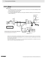
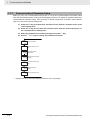
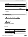
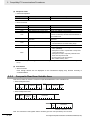
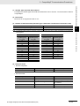
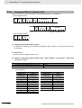
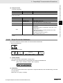
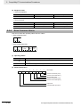
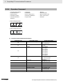
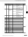
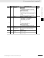
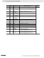
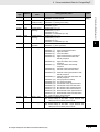
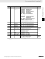
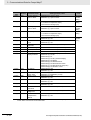
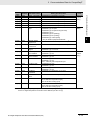
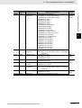
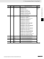
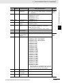
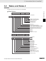
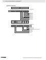
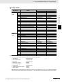
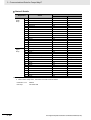
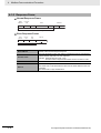
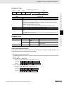
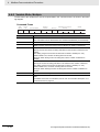
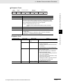
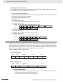
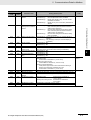
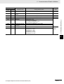
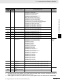
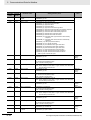
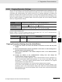
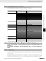
The figure below shows the structure of the status data.
Outputs
3-2 Status and Status 2
z Status Structure
Input error Error status
16 15 14 13 12 11 10 9
8 7
6
5
4
3
2
1
0
Bit position
0
Heater overcurrent (CT1)
Heater current hold (CT1)
A/D converter error
HS alarm (CT1)
RSP input error
3
Input error
Potentiometer input error
Control output (heating)/open output
Control output (cooling)/close output
HB (heater burnout) alarm (CT1)
HB (heater burnout) alarm (CT2)
Alarm 1
Alarm 2
Alarm 3
Program end output
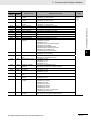
Error status
Operating status
Event inputs
31 30 29 28 27 26 25 24 23 22 21 20 19 18 17 16 15
Bit position
0
Event input 1
Event input 2
Event input 3
Event input 4
Write mode
Non-volatile memory
Setup area
AT execute/cancel
RUN/STOP
Communications writing
Auto/manual switch
Program start
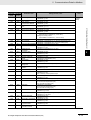
Heater overcurrent (CT2)
Heater current hold (CT2)
HS alarm (CT2)
E5@C Digital Temperature Controllers Communications Manual (H175)
3 - 21