1
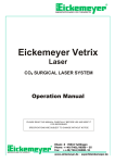
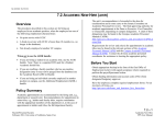
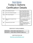
MVL
3D MultiVision
SOFTWARE
OPERATING
INSTRUCTIONS
Changing the market
from level to volume
Accurate, reliable
volume data from
silos, open bins and
warehouses where the
diameters or areas are
exceptionally large.
English
APM 3D Vision and 3D MultiVision
Software Operation Manual
Version 1.0
© Copyright 2010. APM Solutions, Inc. All rights reserved.
English
Table of Contents
Document Conventions ..................................................................................... 1
Additional Information...........................................................................................1
Caution, Warning, Danger....................................................................................1
For Your Safety...................................................................................................... 1
Authorized Personnel .............................................................................................1
Warning about Misuse ...........................................................................................2
General Safety Instructions ...................................................................................2
Chapter 1.
Introduction ..........................................................................................3
System Overview.................................................................................................. 4
System Requirements (for Client side only)..................................................... 6
Workflow ................................................................................................................ 7
Chapter 2.
Installing the Software ......................................................................... 9
Prerequisite Information...................................................................................... 9
Installation.............................................................................................................. 9
Chapter 3.
System Configuration ........................................................................15
Connecting to the Multi Scanner Controller ................................................ 15
Starting a New Project ...................................................................................... 16
Chapter 4.
Using the APM 3D Vision or 3D MultiVision Panes ...........................21
Project Pane........................................................................................................ 22
Configuration Pane ........................................................................................... 22
Vessel Configuration ........................................................................................... 23
3DLevelScanner Configurations ....................................................................... 24
Viewing Pane...................................................................................................... 28
Site Level................................................................................................................ 29
Vessel Level........................................................................................................... 31
Scanner Level ....................................................................................................... 41
APM Solutions APM 3D Vision and 3D MultiVision Software Operation Manual Version 1.0 iii
English
Appendix A. Software Menus........................................................................................43
File Menu.............................................................................................................. 43
Edit Menu............................................................................................................. 45
View Menu........................................................................................................... 47
Project Menu....................................................................................................... 49
Tools Menu........................................................................................................... 50
Managing Reports............................................................................................... 50
General Tools........................................................................................................ 53
Help Menu ........................................................................................................... 56
iv Table of Contents
English
About this Document
This software operation manual provides complete instructions for the quick setup and
safe operation of the 3D Vision and MultiVision applications. This manual is designed for
trained personnel. Read it carefully before you proceed.
By default, this manual refers to the single-vessel 3D Vision license. Unless otherwise
indicated, all information applies equally to the 3D Vision and 3D MultiVision application
licenses.
For information on upgrading from the 3D Vision license to the 3D MultiVision license,
contact APM Solutions, Inc.
Document Conventions
The following conventions are used throughout this document.
Additional Information
Indicates additional helpful information.
Caution, Warning, Danger
Indicates a potentially dangerous situation, which could result in injury, damage, or a loss of
information security.
For Your Safety
Authorized Personnel
All tasks described in this manual should be performed by authorized trained personnel
only. For safety and warranty reasons, any internal work on the devices must be
performed by manufacturer authorized personnel only.
APM Solutions APM 3D Vision and 3D MultiVision Software Operation Manual Version 1.0 1
English
Warning about Misuse
Inappropriate or incorrect use of the device can cause application-specific hazards, such
as vessel overfill, or damage to system components through incorrect mounting or
adjustment.
General Safety Instructions
The 3DLevelScanner is a high technology device requiring strict observance of standard
regulations and guidelines. The user must take note of the safety instructions in this
operating manual, as well as country-specific installation standards (e.g., the VDE
regulations in Germany), and all common safety regulations and accident prevention
rules.
2 Introduction
English
1
Introduction
APM 3D Vision enables real-time assessment of inventories of bulk solids and powders
stored in storage vessels of any type or size, providing managers with accurate and timely
information on which to base critical decision-making for successful plant management.
APM 3D Vision works in conjunction with the APM’s 3DLevelScanner non-contact
volume sensors to provide measurement data to a Windows®-based computer. The
application collects data from the monitored vessel and generates reports that can be used
to increase operational efficiency and provide valuable real-time and historical data for
effective decision making.
APM 3D MultiVision enables you to perform the same functions for groups of vessels,
even across multiple sites. In conjunction with the APM’s 3DLevelScanner non-contact
volume sensors, 3D MultiVision collects data from all monitored vessels in all sites and
geographic regions, combines and merges the data, and generates reports.
Managers and staff with appropriate authorization can view this information from any
location in the world over a common LAN or wireless communication.
APM Solutions APM 3D Vision and 3D MultiVision Software Operation Manual Version 1.0 3
English
Figure 1 3D MultiVision Output Example
System Overview
The general configuration of the system is RS485 daisy chain connections between all
3DLevelScanners, ending in a connection to a controller (Figure 2).
Figure 2 LAN Configuration Example Diagram
4 Introduction
English
The system follows a client-server orientation. The APM Multi Scanner Controller
application runs on a PC which is connected to all the scanners in the system. The client
application can either run on the Controller, or on a remote PC connected to the Multi
Scanner Controller via a network.
The APM Multi Scanner Controller is connected to the LAN / WAN and can be accessed
using its unique IP address.
In general there are two types of remote network connections to the Multi Scanner
Controller from any remote Client:
Access from a local network – LAN.
Access from the public network worldwide – WAN (pending IT authorization).
When accessing the Multi Scanner Controller from the local network, use its configured
local IP address (e.g., 192.168.2.100) and IP Port: 22222.
When accessing the Multi Scanner Controller with a client PC outside the network (WAN
/ Internet) then the plant’s router must forward communication from IP Ports 22221
and 22222 to the local IP address of the Multi Scanner Controller (e.g., 192.168.2.100). This
is known is port forwarding.
Examples (refer to Figure 3):
1) If a user operating a local client PC within the local network (LAN) wishes to connect
to the Multi Scanner Controller, the user must connect to IP address 192.168.2.100 and
IP port 22222. All 3 PCs in the example can connect to the Multi Scanner Controller in
parallel.
2) If a user operating a remote client PC via the Internet (WAN) wishes to connect to the
Multi Scanner Controller, the user must connect to IP address 212.235.113.27 and to IP
port 22222. The router must be configured to forward communications from IP Port
22221 and 22222 to the local IP address 192.168.2.100.
Every user in the system with an adequate permission level (Viewer or above) operating either a
local or remote client PC can change the controller’s parameters and configuration. These changes
apply for all clients.
APM Solutions APM 3D Vision and 3D MultiVision Software Operation Manual Version 1.0 5
English
Figure 3 WAN Configuration Example Diagram
System Requirements (for Client side only)
The following are the system requirements:
Hardware:
Required space on HD:
12 MB (for APM application only)
Log file:
2.8 MB / day
CDROM drive or USB port
At least 1 serial port (built in RS232 / USB )
Processor:
Memory:
minimum 64 MB RAM
6 Introduction
Pentium 1GHz
English
Hard disk:
Minimum 1 GB free memory on HD per year if
Log file is enabled
Graphic resolution:
Minimum 1024X768
Interfaces:
RS232, USB (depending on configuration)
Operating system:
Windows XP, Microsoft® .NET framework 3.5,
SP1
Workflow
For instructions on how to connect to the 3DLevelScanner in various ways, see the
Different Ways of Connecting to 3DLevelScanner document.
1. Install the 3D Vision application in the Client PC. Refer to Installing the Software on
page 9.
2. Run and configure the 3D Vision application on the intended Multi Scanner
Controller. Refer to System Configuration on page 15.
APM Solutions APM 3D Vision and 3D MultiVision Software Operation Manual Version 1.0 7
English
2
Installing the Software
After gathering the recommended perquisite information, you can install the 3D Vision
application.
Prerequisite Information
It is recommended to gather the following information relating to the connection of each
3DLevelScanner prior to installing the software and making the connections.
Multi Scanner Controller Communication port number (Serial COM port) of the bus to
which the 3DLevelScanners are connected.
Multi Scanner Controller Communication IP Address and IP Port.
3D LinkPro Static IP Address for remote wireless commutation
Polling address of each 3DLevelScanner [00 – 63]
Product information – Density (for accurate weight measurement) and the product
name.
For more information on how to connect to the 3DLevelScanner in various ways, see the
document Different Ways of Connecting to 3DLevelScanner.
For more information about performing the hardware configuration, see the document
Multiple Scanners Operating Instructions.
Installation
If you are using the APM Multi Scanner Controller PC system, the 3D Vision application
is already installed on that controller. Skip to System Configuration on page 15.
To install the software:
1. Insert the APM software CD into the computer.
APM Solutions APM 3D Vision and 3D MultiVision Software Operation Manual Version 1.0 9
English
2. The installation application should run automatically. If it does not, browse the CD
contents and manually run the file APM 3DLevelVisionSetup.msi. The 3D Vision setup
wizard opens (Figure 4).
Figure 4 3D Vision Setup Wizard
3. Click Next.
If the PC on which you are installing APM 3D Vision does not have Microsoft® .NET
framework 3.5, SP1 installed, the 3D Vision setup wizard automatically detects this
and prompts you to install the framework at this stage.
The 3D Vision setup wizard proceeds to the Select Installation Folder screen (Figure 5).
10 Installing the Software
English
Figure 5 3D Vision Setup Wizard – Select Installation Folder Screen
4. If the computer on which the software is being installed has multiple user accounts,
select one of the following:
Everyone to make the software available to all the computer users.
Just me to make the software available to the present user account only.
5. Click Next. The Confirm Installation screen appears.
APM Solutions APM 3D Vision and 3D MultiVision Software Operation Manual Version 1.0 11
English
Figure 6 3D Vision Setup Wizard – Confirm Installation Screen
6. Click Next to confirm the installation (Figure 6). The APM software is installed
(Figure 7).
Figure 7 3D Vision Setup Wizard – Installing 3D Vision Setup Screen
After all the necessary files are loaded and installed, the Installation Complete screen
appears, notifying that the APM software installation was completed successfully
(Figure 8).
12 Installing the Software
English
Figure 8 3D Vision Setup Wizard – Installation Complete Screen
7. Click Close to finish the installation of the APM Software. The installer places the
following shortcut icon on your desktop.
Figure 9 APM 3D Vision Shortcut Icon
APM Solutions APM 3D Vision and 3D MultiVision Software Operation Manual Version 1.0 13
English
3
System Configuration
The process of configuring the system includes connecting to the Multi Scanner Controller
and starting a new project.
Connecting to the Multi Scanner Controller
To connect to the Multi Scanner Controller from the 3D Vision application:
1. Double-click the APM 3D Vision shortcut on your desktop.
Or
Click Start | Programs | APM | APM 3D Vision.
The 3D Vision application opens and displays the Controller Connection window
(Figure 10).
Figure 10 3D Level Application Opening Screen with Controller Connection Window
APM Solutions APM 3D Vision and 3D MultiVision Software Operation Manual Version 1.0 15
English
2. In the Server Address field, enter the IP address of the Multi Scanner Controller:
If you are running the client on the Multi Scanner Controller PC, enter the local IP
address for the Multi Scanner Controller on your network.
If you are running the client on a remote PC, enter the global IP address for the
Multi Scanner Controller.
3. In the Controller Port field, verify that the entered server port is 22222.
4. Click Connect. The application connects to the Multi Scanner Controller and you are
prompted to enter your username and password (Figure 11).
Figure 11 APM Vision Login Window
5. Enter a username and password. The default username and password are both
“admin” (case sensitive).
It is important to define the usernames, passwords, and permission levels of the various user
accounts prior to setting up projects in the system. Refer to User Management on page 54.
At least one user account must have the administrator permission level.
Starting a New Project
After logging in to the Multi Scanner Controller, you are prompted to start a new project
or open an existing project (Figure 12).
16 System Configuration
English
Figure 12 New Project Button
For information on navigating the panes and menus mentioned in the section, refer to
Chapter 4: Using the APM 3D Vision or 3D MultiVision Panes on page 21 and Appendix A:
Software Menus on page 43 as necessary.
To start a new project:
1. Click New Project to create a new project. The Project Details window appears
(Figure 13).
Figure 13 Project Details Window
2. In the Name field, enter a name for the project.
3. Optionally, in the Location field, change the defined location for the project files by
editing the path, or browsing for a new location.
4. Click Finish. The new project is created.
APM Solutions APM 3D Vision and 3D MultiVision Software Operation Manual Version 1.0 17
English
5. Define the connection settings for a 3DLevelScanner as follows:
a. In the project pane on the left side of the screen, select Site | Vessel | <unknown1>
(device tag of the 3DLevelScanner) | Connection. The connection options for the
selected scanner appear (Figure 14).
Figure 14 Scanner Configuration Options
b. In the Serial Port field, select a serial COM port
c. In the Polling Address field, select the scanner’s polling address
d. In the Connection Type area, select the scanner’s connection type.
e. Click
.
6. To add more scanners to the project, repeat step 5 for each scanner.
7. Optionally, perform the following for each site:
a. In the project pane, select a site. The configuration options for the site appear
(Figure 15).
18 System Configuration
English
Figure 15 Site Configuration Options
b. In the Name field, enter a name for the site.
c. In the Description field, enter a description for the site, for example its location or
the number of vessels it contains.
8. Perform the following for each vessel:
a. In the project pane, select a vessel. The configuration options for the vessel appear
(Figure 16).
Figure 16 Vessel Configuration Options
b. In the Name field, enter a name for the vessel.
APM Solutions APM 3D Vision and 3D MultiVision Software Operation Manual Version 1.0 19
English
c. In the Description field, enter a description for the vessel, for example its location in
the plant.
d. In the Material field, browse to select the material contained in the vessel. For
information on defining the list of available materials, refer to Material Color on
page 53.
9. Click
Or
Click File | Save.
The project is saved.
10. Click
and
to hide the project and configuration panes respectively. The
viewing pane is displayed, enabling you to monitor of the sites, vessels, and sensors.
20 System Configuration
English
4
Using the APM 3D Vision or 3D
MultiVision Panes
There are 3 main areas in the 3D Vision application (Figure 17).
Figure 17 Main Panes
1. Project Pane – Enables you to navigate between sites, vessels, and scanners in a
project.
2. Configuration Pane – Enables you to configure site, vessel, and scanner details.
3. Viewing Pane – Enables you to view each vessel with its measurements (volume,
distance, mass, etc.).
APM Solutions APM 3D Vision and 3D MultiVision Software Operation Manual Version 1.0 21
English
You can toggle the display of these panes by clicking their respective icons:
– Project Pane.
– Configuration Pane.
–Viewing Pane.
Alternatively, open the View menu and click the name of the panes to show or hide the
panes.
Project Pane
The project pane displays a navigation tree which represents all of the 3DLevelScanners
in a project.
Each project is organized in a hierarchical structure as follows. The project is at the top of
the hierarchy. Under the project is a list of sites. Under each site is the list of vessels
located at the site. Under each vessel is the list of scanners associated with the vessel. For
example, in a single project there could be multiple sites (or multiple groups of vessels), in
each site or group there could be multiple vessels, and in each vessel there might be one
scanner.
In the example in Figure 17, there is a single site called Manual Plant. The site has eight
vessels (G1, G2, G3, G4, 30, 31, 32, 33) and in each vessel there is a single 3DLevelScanner
(labeled polling x).
Each 3DLevelScanner has its configuration (Connection, Basic Settings, Linearization, and
Display), which can be viewed in the configuration pane.
Configuration Pane
The Configuration Pane enables you to view the configuration details for the various sites,
vessels, and scanners in a project.
Figure 18 Configuration Pane – Site Example
22 Using the APM 3D Vision or 3D MultiVision Panes
English
The configuration pane also enables you to add and remove sites, vessels, and scanners
from the project.
While viewing the configuration options for a site, click
to add a vessel.
Or
While viewing the configuration options for a site, from the menu bar select Edit | Add
| Vessel.
While viewing the configuration options for a site, click
selected site.
to delete the
Or
While viewing the configuration options for a site, from the menu bar select Edit |
Delete | Site.
To add a site to the project, from the menu bar click Edit | Add | Site.
In the configuration pane, you can enter a site name and a site description. In the example
of Figure 17, the site name is Manual Plant and the description is This is a virtual plant for
the user manual.
Vessel Configuration
Figure 19 Configuration Pane – Vessel Example
While viewing the configuration options for a vessel, click
scanner.
to add a
Or
While viewing the configuration options for a vessel, from the menu bar select Edit |
Add | Scanner.
While viewing the configuration options for a vessel, click
selected vessel.
to delete the
Or
While viewing the configuration options for a vessel, from the menu bar select Edit |
Delete | Vessel.
APM Solutions APM 3D Vision and 3D MultiVision Software Operation Manual Version 1.0 23
English
In the 3D Vision application, version 1.0.x, it is possible to view and control only a single
vessel. For adding more vessels a software upgrade to 3D MultiVision is needed.
In the configuration pane, under the General tab, you can enter the vessel name, the
vessel description, and you can either browse to select the material which the vessel
contains, or from the menu bar select Tools | Material Color.
In the example of Figure 17, the vessel name is set to G1, the description is Flour for the
end user, and the Material is Flour.
Under the Shape tab (Figure 20), the vessel geometry can be viewed.
Figure 20 Configuration Pane – Vessel Example – Shape Tab
In the 3D Vision application, version 1.0.x, the vessel shape parameters can only be
viewed. To change the parameters, you must use the 3DLevel Manager Software Tool.
3DLevelScanner Configurations
Figure 21 Configuration Pane – Scanner Example
The following 3DLevelScaner tasks can only be performed from the configuration pane
while a 3DLevel Scanner is selected in the project pane. In the example above, Polling 0 is
the selected scanner.
Optionally, enter a description for the 3DLevelScanner.
24 Using the APM 3D Vision or 3D MultiVision Panes
English
Select the Enable checkbox to enable the scanner. When the scanner is enabled, the
measurements are automatically downloaded from the 3DLevelScanner to the
3D Vision application. In the project panel, the connection color is green.
Unselect the Enable checkbox to disable the scanner. When the scanner is disabled, the
measurements are not automatically downloaded from the 3DLevelScanner. In the
viewing pane, the scanner is not monitored, and in the project pane the connection
color is yellow.
In the example below, scanner Polling 0 in vessel G1 is disabled.
Figure 22 Disabled Scanner Example
Optionally, click
to manually download all measurements from the
selected 3DLevelScanner to the 3D Vision application.
Optionally, click
to close the connection between the selected
3DLevelScanner and the 3D Vision application.
APM Solutions APM 3D Vision and 3D MultiVision Software Operation Manual Version 1.0 25
English
Connection Settings
You must define the connection settings for each 3DLevelScanner in the project.
For each 3DLevelScanner, select Connection in the program pane and define the following:
Configuration details:
Serial PC Port.
Polling Address.
Connection Type:
HART.
RS485.
GPRS.
GPRS+SMS.
TCP/IP.
For GPRS, GPRS+SMS and TCP/IP, additional configuration is needed. After selecting
one of these options, the Additional Configuration area is displayed on the right side of the
configuration pane.
In the example below, the connection to 3DLevelScanner <unknown 1>, in vessel G1, in
site Manual Plant is set to polling address 0 and a TCP/IP type connection. The Multi
Scanner Controller IP address and Multi Scanner Controller IP port are also defined in the
Additional Configuration area that appeared for the TCP/IP connection type.
Figure 23 Configuration Pane – Scanner Connection Options
For a more detailed explanation of how to connect to a 3DLevelScanner in various ways,
refer to the document Different Ways of Connecting to 3DLevelScanner.
26 Using the APM 3D Vision or 3D MultiVision Panes
English
Basic Settings
Figure 24 Configuration Pane – Scanner Basic Settings Options
In the program pane, under the selected scanner, select Basic Settings to view the
following:
Empty Calibration.
Full Calibration.
In the example above, the basic settings for Scanner Polling 0, in vessel G1, in site Manual
Plant are 10 and 0 meters for the Empty and Full Calibrations respectively.
In the 3D Vision application, version 1.0.x, the Basic Settings parameters can only be
viewed. To change the parameters, you must use the 3DLevel Manager Software Tool.
Linearization Settings
Figure 25 Configuration Pane – Scanner Linearization Options
In the program pane, under the selected scanner, select Linearization to view the following:
Linearization Mode.
Customer Unit.
Max Scale.
In the example above, the Linearization settings of Scanner Polling 0, in vessel G1, in site
Manual Plant, are Custom mode, customer unit m^3, and the maximum scale of the vessel
is 239 m^3.
APM Solutions APM 3D Vision and 3D MultiVision Software Operation Manual Version 1.0 27
English
In the 3D Vision application, version 1.0.x, the linearization parameters can only be
viewed. To change the parameters, you must use the 3DLevel Manager Software Tool.
Display Settings
Figure 26 Configuration Pane – Scanner Display Options
In the program pane, under the selected scanner, select Display to view the following:
Language.
Back to Home – Time to automatically go to default screen in the scanner’s LCD.
Number of Digits – Number of digits after the decimal point when displaying
measurements.
Distance Unit – Unit of measurement used for distances.
Temperature Unit – Unit of measurement used for temperatures.
In the example above, the Display settings of Scanner Polling 0, in vessel G1, in site Manual
Plant are English language, Back to Home of 300 seconds, 2 digits after the decimal point
in the measurements, the Distance Unit is meters, and the Temperature Unit is Celsius.
In the 3D Vision application, version 1.0.x, the display parameters can only be viewed. To
change the parameters, you must use the 3DLevel Manager Software Tool.
Viewing Pane
The viewing pane has three viewing levels:
Site Level.
Vessel Level.
Scanner Level.
28 Using the APM 3D Vision or 3D MultiVision Panes
English
Site Level
After making all configurations using the project and configuration panes, close the
project and configuration panes to view the site level viewing pane.
The site level viewing pane is the most commonly used pane in the 3D Vision and
MultiVision applications.
Figure 27 Viewing Pane –Site Level MultiVision Example
APM Solutions APM 3D Vision and 3D MultiVision Software Operation Manual Version 1.0 29
English
Double-click a vessel image to open a 3D Profile for that vessel.
Figure 28 3D Vessel Profile – Site Level
Notes:
A 3D Profile is enabled only for MV/MVL scanner types.
Parallel 3D Profiles can be viewed. In the example above, two images are viewed in
parallel.
30 Using the APM 3D Vision or 3D MultiVision Panes
English
Vessel Level
To view the measurements for a vessel:
In the project pane, click a vessel name. The vessel information is displayed.
Figure 29 Viewing Pane –Vessel Level Example
In the example above, vessel 30 is selected, and all measurements for that vessel
(Level/Distance, Volume, Temperature, SNR, 4-20mA Output, etc.) are displayed.
APM Solutions APM 3D Vision and 3D MultiVision Software Operation Manual Version 1.0 31
English
Double-click the vessel image to open a 3D Profile for the vessel.
Figure 30 3D Vessel Profile – Vessel Level
Notes:
A 3D Profile is enabled only for MV/MVL scanner types.
Parallel 3D Profiles can be viewed. In the example above, two images are viewed in
parallel.
The vessel level features the following tabs:
Overview.
Log.
3D.
3D Log.
Advanced 3D (disabled in Viewer Mode).
32 Using the APM 3D Vision or 3D MultiVision Panes
English
Overview
The Overview tab displays the measurements of the vessel:
Level/Distance.
Volume.
Temperature.
SNR.
4-20mA Output.
Alerts
etc.
Under the scanner level the scanner’s information is also displayed:
Serial Number of the electronic card.
Firmware Version.
Hardware Version.
Type of 3DLevelScanner.
Figure 31 Viewing Pane – Vessel Level – Overview Tab
APM Solutions APM 3D Vision and 3D MultiVision Software Operation Manual Version 1.0 33
English
Alerts
The system provides alerts for configuration and system notifications.
•
System Notifications – characterized in red color. When the temperature of a
3DLevelScanner reaches beyond the temperature region of the spec (hence,
beyond -40 to +85 degrees Celsius or -40 to +185 degrees Fahrenheit)
•
Configuration Notifications – characterized in yellow color. When MVL scanner’s
settings do not have the same vessel settings (all the configuration wizard settings
except device position or horizontal angle). The output will be displayed above
the vessel image in yellow font.
Parameters Definition
The system enables the user to choose which measured parameters will be displayed on
screen. Use the right click on the vessel image to launch the Parameters Definition window
(Figure 32).
Data Selection tab, drag the right pane parameters to the left pane for displaying the
parameters. Use the up and down buttons to move parameters up and down
respectively. For mass display, configure the product density in the bottom right corner.
Alerts tab, select the minimum and maximum volume levels for setting system output
alarm. The alarm will be displayed as a red background in the vessel image.
Figure 32 – Parameters Definition Window
34 Using the APM 3D Vision or 3D MultiVision Panes
English
Log
Figure 33 Viewing Pane – Vessel Level – Log Tab
The Log tab displays the following log information in 2D graphical format:
Level / Distance.
Volume.
SNR.
Temperature.
These logs are also displayed online. All log files are saved in the Multi Scanner
Controller .
To automatically download previous log files:
1. Click Offline to exit online logging.
2. Click
. The Search Log window appears (Figure 34).
APM Solutions APM 3D Vision and 3D MultiVision Software Operation Manual Version 1.0 35
English
Figure 34 Search Log Window
3. Select the From and To dates and times to display.
4. Click Run. The log will automatically be displayed (identical to the Run function in the
internet for automatic run of a downloaded file).
5. Click Save. You are prompted to save the selected logs to a location.
To manually download previous log files:
1. Click Offline to exit online logging.
2. Click
. The Search Log window appears (Figure 34).
3. From the Search Log window, click Manual. The Files window appears displaying all
the log files (Figure 35).
36 Using the APM 3D Vision or 3D MultiVision Panes
English
Figure 35 Files Window
4. Select one or more log files.
5. Click Select. You are prompted to save the selected logs to a location.
APM Solutions APM 3D Vision and 3D MultiVision Software Operation Manual Version 1.0 37
English
3D Log
Figure 36 Viewing Pane – Vessel Level – 3D Log Tab
The 3D Log tab displays the minimum/maximum and average distance/level
measurement values for the vessel.
The 3DLog is displayed online. All 3D Log files are saved to the Multi Scanner Controller
.
To automatically download previous 3D log files:
1. Click Offline to exit online logging.
2. Click
. The Search Log window appears (Figure 34).
3. Select the From and To times to display.
4. Click Select. You are prompted to save the selected logs to a location.
To manually download previous 3D log files:
1. Click Offline to exit online logging.
2. Click
. The Search Log window appears (Figure 34).
3. From the Search Log window, click Manual. The Files window appears displaying all
the log files (Figure 35).
38 Using the APM 3D Vision or 3D MultiVision Panes
English
4. Select one or more log files.
5. Click Select. You are prompted to save the selected logs to a location.
3D
The 3D tab displays the visual mapping contour as scanned by the 3DLevelScanners
(enabled for MV type scanners only).
Figure 37 Viewing Pane – Vessel Level – 3D Tab
To rotate the 3D image, left-click the 3D image and drag it.
For MV/MVL types of 3DLevelScanners, the application records 3D mapping images
periodically. You can view these images as a movie when working offline (i.e. not
connected to a scanner).
To watch a 3D image movie:
1. To the right of the 3D Log field, click
folder. The movie is uploaded.
to browse for a 3D Log file from the 3DLog
APM Solutions APM 3D Vision and 3D MultiVision Software Operation Manual Version 1.0 39
English
2. Use the movie controls to start and stop the movie.
Figure 38 Movie Controls
The Interval field defines the amount of time that elapses between each image in the
movie. Effectively, this is the speed of the movie.
Advanced 3D
The Advanced 3D tab displays the mapping points measured in the vessel.
The Advanced 3D tab is enabled in all permission levels except for Viewer mode.
The # column displays the scanner in the system to which each mapping point is
associated.
Figure 39 Viewing Pane – Vessel Level – Advanced 3D Tab
40 Using the APM 3D Vision or 3D MultiVision Panes
English
Scanner Level
To view the measurements of each scanner in a vessel:
In the project pane, click a scanner name. If there is more than one scanner, a list of all the
scanners mounted to the selected vessel appears. In addition, the scanner level of the
viewing pane displays all the measurement for the scanner. The displayed information is
identical to that of the vessel level of the viewing pane. For more information, refer to
Vessel Level on page 31.
Notes:
When working with 3DLevelScanner types S/M/MV, there is only one scanner
installed per vessel, so there is no unique scanner level for the viewing pane.
When working with 3DLevelScanner type MVL, there is more than one scanner
mounted on each vessel, and users with a suitable permission level can view the
individual measurements of each scanner.
APM Solutions APM 3D Vision and 3D MultiVision Software Operation Manual Version 1.0 41
English
A
Software Menus
The following sections provide information regarding the options available in each menu
of the 3D Vision application.
File Menu
Figure 40
New (Ctrl+N) — Creates and open a new project (all sites, vessels, and
3DLevelScanners undefined). The toolbar button for New is
.
APM Solutions APM 3D Vision and 3D MultiVision Software Operation Manual Version 1.0 43
English
Open — Opens an existing project for local browsing. The toolbar button for Open is
.
Save – Saves the present project. The toolbar button for Save is
.
Save As – Saves the present project under a different name.
Export Project from Multi Scanner Controller – Downloads a project from the Multi
Scanner Controller to the client PC. This function opens a list of all the saved projects
in the Multi Scanner Controller, as demonstrated below.
Figure 41 List of Saved Projects on the Multi Scanner Controller
Import Project to Multi Scanner Controller – Uploads a project from the client PC to
the Multi Scanner Controller. This function opens a browser for selecting one or more
projects on the client PC to upload.
44 Using the APM 3D Vision or 3D MultiVision Panes
English
Figure 42 Browser for Selecting a Project on the Client PC
Delete Project – Enables you to delete a project from the Multi Scanner Controller.
This function opens a list of all the saved projects in the Multi Scanner Controller and
enables you to select a project to delete.
The Import and Export functions are for maintenance and support. For example, a user
wants to download a project to a local PC in order to make changes to the project, and
then upload the edited project back to the Multi Scanner Controller.
List of recent projects – Enables you to view a list of all the recent projects that were
opened on your local PC.
Exit – Exits the present project and closes the 3D Vision application.
Edit Menu
Add ► – Adds sites, vessels, or scanners depending on the level selected in the project
pane.
On the site level it adds sites or vessels.
On the vessel level it adds scanners.
On the scanner level it is disabled.
APM Solutions APM 3D Vision and 3D MultiVision Software Operation Manual Version 1.0 45
English
Figure 43 Edit Menu – Add Options
Delete ► – Deletes sites, vessels, or scanners depending on the level selected in the
project pane.
On the site level it deletes sites.
On the vessel level it deletes vessels.
On the scanner level it deletes scanners.
Figure 44 Edit Menu – Delete Options
46 Using the APM 3D Vision or 3D MultiVision Panes
English
View Menu
Figure 45 View menu Options
View Project / Configuration / Visual panes – Enables you to display or hide panes.
The View menu options of Project, Configuration Pane, and Visual Pane are
equivalent to clicking
,
, and
respectively.
Level / Distance Data – Enables you to select either level or distance for displaying the
quantity of material in vessels. The selection applies for measurements in all viewing
panes, at all view levels, for the corresponding values (min / max / average).
This can also be achieved by clicking
/
.
APM Solutions APM 3D Vision and 3D MultiVision Software Operation Manual Version 1.0 47
English
In the figure below, D indicates “distance” and L indicates “level”.
Figure 46 Distance Versus Level Diagram
48 Using the APM 3D Vision or 3D MultiVision Panes
English
Project Menu
Figure 47 Project Menu Options
Connect All — The project automatically connects to all the configured scanners (that
were predefined in the connection options. For more information, see Connection
Settings on page 26.
Disconnect All — The project automatically closes communication to all scanners.
APM Solutions APM 3D Vision and 3D MultiVision Software Operation Manual Version 1.0 49
English
Tools Menu
The tools menu includes the reporting functions.
Figure 48 Tools Menu – Report Options
Managing Reports
The 3D Vision application enables you to create reports in Microsoft® Excel file format.
The reports are generated online according to the report configuration.
The report options are:
Open last report folder — Opens the local PC folder in which all Excel report files are
saved.
50 Using the APM 3D Vision or 3D MultiVision Panes
English
Figure 49 Reports File Folder Example
Export Report Files from Multi Scanner Controller – Exports report files from the
Multi Scanner Controller to the client PC.
This function opens a window with all the reports of all projects saved on the Multi
Scanner Controller (Figure 35). Select one or more report files to download from the
Multi Scanner Controller to the client PC.
Export Selected Project Report Files from Multi Scanner Controller - Exports the
report files of the present project running in the Multi Scanner Controller to the client
PC.
This function opens a window with the reports of the present project in the Multi
Scanner Controller. Select one or more report files to download from the Multi
Scanner Controller to the client PC.
In order to open report files on the client PC, Microsoft® Excel must be installed.
APM Solutions APM 3D Vision and 3D MultiVision Software Operation Manual Version 1.0 51
English
Configure – Enables you to configure the report settings.
Figure 50 Report Configuration Window
The Report Configuration window enables you to set times when each report is
generated, and define the measurements that are included in the reports:
The top area of the Report Configuration window enables you to manually define
the hours in which reports are generated per day.
Alternatively, you can click Every Hour to define that reports are generated on an
hourly basis over the course of a day.
In the Report Period area, you can select whether reports are generated on a Daily,
Weekly, or Monthly basis. When selecting weekly reports, in the Week start day field
you must select the day in which each weekly period should begin.
In the Data Collection area, select one or more of the following measurement types
to be included in each report:
Distance.
Level.
Volume (%).
Volume – Based on the customer-defined unit.
Mass.
Optionally, in the Report output directly field, you can modify the directory to which
reports are saved.
52 Using the APM 3D Vision or 3D MultiVision Panes
English
Each generated report is saved as a separate Excel file in the defined reports output
folder.
In generated reports, each row contains data for a scanner, and each column contains
data for a point in time.
General Tools
Material Color – Enables you to set the colors that correspond to the materials in
vessels when displayed in the viewing pane.
Figure 51 Material Color Definition Window
Senior Technician Mode - Enables you to switch to Senior Technician mode, which
provides advanced options for changing parameters. Switching to Senior Technician
mode requires a password.
Connect to Multi Scanner Controller – Closes the current connection to the Multi
Scanner Controller and enables you to open a new connection to a different Multi
Scanner Controller. You must enter the new server address and server port.
Figure 52 Server Connection Window
APM Solutions APM 3D Vision and 3D MultiVision Software Operation Manual Version 1.0 53
English
Server Synchronization – Downloads and synchronizes all parameters from the Multi
Scanner Controller to the client PC.
For example, if other client PCs are connected in parallel to the same Multi Scanner
Controller, and one client changes a parameter, the change takes effect for all clients
connected to that server. Performing server synchronization synchronizes the settings
on the client PC to the settings on the Multi Scanner Controller.
Switch User – Enables you to switch between user accounts.
This function opens a window to enter a new username and password. Doing so
automatically logs off the current user and logs in using the new user account.
Figure 53 Switch User Window
Each user account has its own defined permission level. If you switch to a user account with
a lower permission level, you will be more limited in the actions you can perform.
User Management - This function opens the Users window which displays a list of all
the user accounts defined on the Multi Scanner Controller and their permission levels.
Figure 54 Users Window
54 Using the APM 3D Vision or 3D MultiVision Panes
English
The Users window enables users with administrator permission to add, remove, or
edit user accounts:
Add – In the Users window, click Add. The New User window opens. Define the
username, password, and permission level for the new account, and click OK.
Figure 55 New User Window
Remove – In the Users window, select a user account and click Remove.
Edit – In the Users window, select a user account and click Properties. A window
opens, enabling you to edit the password and permission level for the selected user
account. Click OK to confirm the changes.
Figure 56 Editing User Account Properties – Example for User admin
License Key – Enables you to upgrade from the single-vessel 3D Vision software
license to the 3D MultiVision software license by entering a new license key. The
change takes effect immediately and does not require a restart of the client PC.
Figure 57 – license key window
APM Solutions APM 3D Vision and 3D MultiVision Software Operation Manual Version 1.0 55
English
Help Menu
About — Displays the 3D Vision software version and support details.
Figure 58 About Window
56 Using the APM 3D Vision or 3D MultiVision Panes
MVL
3D MultiVision
You can find at
www.apm-solutions.com
downloads of the following:
SOFTWARE
OPERATING
INSTRUCTIONS
• Brochures
• Data Sheets
• Operating instructions
manuals
• Software
• Certificates
• Product information
and much, much more
Accurate, reliable volume data from silos,
open bins and warehouses where the
diameters or areas are exceptionally large.
Represented by
© 2009 APM Automation Solutions Ltd. All rights reserved. Information in this
document is subject to change without notice. APM Automation Solutions Ltd.
and the APM Logo, are trademarks, and the 3DLevelScanner is a registered
trademark of APM Automation Solutions Ltd.
MAN0001500
APM Automation Solutions Ltd.
ATIDIM High-Tech Industrial Park
Building 2 P.O. Box 58171
Tel Aviv 61580, Israel
Tel: +972 3 6488891
Fax: +972 3 6488892
[email protected]
www.apm-solutions.com