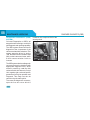
1
Owner's Manual
Passenger Vehicle Business Unit (PVBU)
• Mumbai • Pune •
1
NOTE
• This manual explains important features and instructions intended to assist you in gaining
maximum use and satisfaction. Therefore, always keep this in the vehicle for ready reference.
• All information, illustrations and specifications contained in this manual are based on the latest
product information available at the time of publication.
• TATA MOTORS LIMITED reserves the right to make changes in design and specifications and/or
to make additions or improvements in this product without obligation to install them on the vehicles
previously sold.
• This owner's manual includes information on the operation and maintenance of various features
installed on the different variants. Please note that this manual applies to all the variants and
explains all features including options which may not be applicable to your vehicle.
• All rights reserved. The information in this manual may not be reproduced or copied, in whole or in
part, or in any form without prior written permission from TATA MOTORS.
© Copyright 2014 TATA MOTORS
2
FOREWORD
Dear Customer,
Welcome to the TATA MOTORS family.
We congratulate you on the purchase of your new vehicle and
are privileged to have you as our valued customer. Your selection
of our product exhibits the trust you have in us.
This manual will familiarize you with operational, maintenance
and safety information of your new vehicle. We urge you to read
this manual carefully and follow the recommendations to ensure
enjoyable and safe operation of your new vehicle.
We recommend that all service and maintenance on your vehicle
should be performed by an authorized TATA MOTORS DEALER
/ TATA MOTORS Authorised Service Centres (TASCs) to
ensure that only latest methods and genuine replacement parts
are used for continued reliability, safety and performance of your
vehicle.
You are welcome to contact our dealer or Customer Assistance
toll free no. in case of any query or support.
We wish you a safe and pleasant driving experience.
3
CUSTOMER ASSISTANCE
Dear Customer,
In our constant endeavour to provide assistance and
complete service backup, TATA MOTORS has established
an all India customer assistance centre.
In case you have a query regarding any aspect of your
vehicle, our Customer Assistance Centre will be glad to
assist you on our Toll Free no. 1800-209-7979
4
You can also approach nearest TATA MOTORS dealer.
A separate Dealer network address booklet is provided
with the Owner’s manual.
TATA MOTORS 24X7 Roadside Assistance Program
offers technical help in the event of a breakdown. Call to
the toll-free Roadside Assistance.
For additional information, refer to "24X7 Roadside
Assistance" section in the Owner’s manual.
CONTENTS
1
SAFETY & SECURITY
2
OPENING & CLOSING
3
INSTRUMENTS & CONTROLS
Important Safety Notes
9
Key
25
Cockpit
34
Safety Guidelines
9
Keyless Entry - E Key Operation
Doors
25
29
Instrument Cluster
35
Instruments (Gauges)
37
30
32
Driver Information Display.
39
Seat Belts
10
Child Restraint System
12
Child lock
17
Window Glasses
Bonnet
Tell tales (Indicators)
46
18
Fuel Lid
33
Combination Switch
51
Supplemental Restraint System Air Bags
20
Trunk lid
33
Fascia Switches
54
Steering Wheeel Switches
56
Infotainment System
57
Roof Lamp
58
Luggage Compartment Lamp
58
Anti-theft Device - Immobilizer
Anti-Lock Braking System
01
22
Electronic Brake Force
Distribution
22
Engine Drag Torque Contol
22
Cornering Stability Control
22
Driving in Adverse Conditions
23
02
03
5
CONTENTS
4
STOWAGE & FEATURES
5
CLIMATE CONTROLS
6
Glove Box
59
Air Vents & Distribution
62
Utility Tray & Pockets
Cup Holders
59
59
Manual HVAC
63
Power Socket
Roof Grab Handle
60
60
FATC - Fully Automatic Temp.
Control
67
Luggage Compartment
Luggage Cover
61
61
04
6
05
STARTING & DRIVING
Pre-driving Checks
Safety Checks
Fuel Saving Tips
Good Driving Practices
Running-In Period
Seat & Seat Adjustments
Rear View Mirrors
Sun Visors
Steering Wheel Angle Adjustment
Preparing to drive
Steering Lock cum
Ignition Switch
Gear Lever & Shifting Pattern
Drive Modes
Brakes & Braking
Parking Brake
Vehicle Parking
Reverse Park Assist
06
74
75
76
77
77
78
80
81
82
82
83
84
88
90
91
91
92
CONTENTS
7
EMERGENCY & BREAK DOWN
ASSISTANCE
8
MAINTENANCE & SERVICING
9
TECHNICAL INFORMATION
Hazard Warning Switch
95
Engine Compartment
123
Fuel Specification
140
First Aid Kit
Advance Warning Triangle
96
96
Engine Oil Level
125
Lubricants Specification
141
Brake Fluid Level
125
Coolant Specification
141
Tool Kit
Jack & Handle
97
97
Engine Coolant Level
126
Transaxle Oil Level
127
Lubricants & Coolant
Co-branding
142
Flat Tyre Replacement
Spare Wheel
Jump Lead Start
98
98
101
Windshield Washer Fluid Level 127
Technical Specifications
143
Spark Plug (Petrol Engine)
128
Vehicle Dimensions
146
147
103
105
129
Identification Plates
Towing The Vehicle
Fuses
Tyres
Battery
132
Bulb Specifications & Bulb
Replacement
24 X 7 On Road Assistance
111
07
118
08
Remote Battery
133
On Board Diagnostic (OBD)
134
Routine Service
135
Vehicle Service
136
Service Schedule
137
09
7
CONTENTS
10
CAR CARE & VALUE ADDED
SERVICES
Car Care
149
Washing
149
Waxing
150
Polishing
150
Interior Fabric Cleaning
150
Paint Care
151
Wiper Care
151
Vehicle Parking For Long
Duration
152
10
Value Added Services
8
153
11
WARRANTY - TERMS AND
CONDITIONS
162
12
ENVIRONMENT SAFETY
164
13
ALPHABETICAL INDEX
166
IMPORTANT SAFETY NOTES & SAFETY GUIDELINES
IMPORTANT SAFETY NOTES:
SAFETY GUIDELINES:
In this Owner's Manual, you will find
the following safety notes.
Safe driving depends on:
NOTE
Indicates additional information that
will assist you in gaining the
optimum benefit and care for your
vehicle.
WARNING
Indicates procedures or information
that must be followed precisely in
order to avoid the possibility of
severe personal injury and serious
damage to the vehicle.
• How quickly you make decisions
to avoid an accident.
• Your ability to concentrate.
• How well you can see and judge
objects.
Few safe driving general tips are
listed below.
SAFETY
factors. Take rest at regular intervals.
• If your vehicle is equipped with a
navigation system, set and make
changes to your travel route only
with the vehicle parked.
• Program radio presets with the
vehicle parked, and use your
programmed presets to make
radio use quicker and simpler.
• Take into account the traffic, road,
and weather conditions, particularly
with regard to stopping distance.
• Never drive under the influence of
alcohol or drugs.
• Refrain from using a cell phone
while driving.
• Fatigue is a result of physical or
mental exertion that impairs judgement. Driver fatigue may be due to
inadequate sleep, extended work
hours, strenous work or non-work
activities or combination of other
9
01
01
SAFETY
SEAT BELTS:
Seat-belt is a safety device designed
to secure the occupant of the vehicle.
Use of seat-belt reduces the chance
of injury and severity of injury in case
of an accident. TATA MOTORS
strongly recommends that all the
occupants should always wear seatbelts while travelling, irrespective of
journey duration.
Your vehicle is equipped with seat
belts, for front and rear seats as a part
of occupant restraint system.
WARNING
Be sure everyone in your vehicle is
seated and using a seat belt
properly.
In normal driving, the belt lets you
move freely in your seat. In case of an
accident or sudden braking, inertia reel
automatically tightens the belt to help
restrain your body.
10
SEAT BELTS
This vehicle has three point inertia reel
type for front and rear seat belts in the
out board positions and a lap belt for
middle passenger on rear seat. The lap
belt has a manually adjusted belt that
fits across the hip bone. Make sure
that your seat is adjusted to a good
driving position and the back of the
seat is upright.
Importance of Wearing Seat Belt :
1. It will help to keep you in the proper
position when the air bag inflates.
2. Reduces the risk of harm in rollover,
side or rear impact collisions
3. Reduces the risk of harm in
frontal/angular collisions that are
not enough to activate the air bag.
4. Reduces the risk of being thrown
inside the vehicle in case of a
collision.
NOTE
Do not bleach or dye seat belts as
this may severely weaken them. In
a crash they may not be able to
provide adequate protection. Cleaning should be carried out using mild
soap and water only.
WARNING
Make sure that the seat belts are
not twisted which can cause injury
in a collision as the full width of the
belt isn’t available to absorb the
impact. This puts more force on the
bones beneath the belt, which could
cause serious injury.
The maximum protection which seat
belts can offer is only achieved if you
are correctly seated. The seat back
should not be tilted too far back.
SEAT BELTS
SAFETY
How to use seat belts:
LATCH
1. Pull the belt tongue across your
body and insert it into the buckle.
2. Check and ensure that the belt is
not twisted.
3. Position the lap portion of the belt
as low as possible across your hip
bone.
4. Pull up the shoulder part of the belt
to remove the slack. Make sure that
the belt goes over your collar bones
and across chest.
5. To unlatch the belt, press the red
button on the buckle. Guide the belt
to the pillar as it retracts.
WARNING
1. The belts are intended for adult
occupants only.
2. Each belt should be used by one
occupant only. The belt must not
be put round a child, seated on
passengers lap.
3. Use approved child restraint
system for children
4. If the belt was in use in a serious
accident or shows signs of severe
fraying / damage or of having been
cut, replace it with an approved
belt kit.
5. The belt must not be altered or
modified during use and if required
to be replaced, then it should be
replaced, by TATA MOTORS
Authorized Service Centre only.
UNLATCH
1. Buckle 2.Tongue 3.Press Button
11
01
01
SEAT BELTS
SAFETY
Lap belt:
Pregnant Woman:
Pull the belt tongue to the desired
length. Insert it into the buckle until
you hear a click.
A pregnant woman should wear a Lapshoulder belt and the lap portion should
be worn as low as possible, below the
womb, throughout the pregnancy.
When a safety belt is worn properly, it
is more likely that the foetus will not
be hurt in a crash. Pregnant women
should wear the lap part of the belt
across the thighs and as snug across
the hips as possible. Keep the belt low
so that it does not come across the
abdomen. By doing this, the strong
structure of the hips will take the force
if there is a collision.
Adjust the belt length. To lengthen the
belt, hold the tongue at a right angle
to the webbing and pull. To shorten,
pull the loose end of the webbing. To
unfasten, depress the button in the
buckle.
WARNING
Positioning the lap portion of the
Seat Belt too high can be dangerous as in a collision; this would
concentrate the impact force directly
on the abdominal area, causing
serious injury. Wear the lap portion
of the belt snugly and as low as
possible.
12
SEAT BELTS
SAFETY
Child Restraint System (CRS) :
Selection of CRS :
TATA MOTORS strongly recommends
the use of Child Restraint Systems
(CRS) for all children up to the age of
12 (see the Table in the next page for
applicability for your child).
Not every child will fit in the CRS specified for his or her weight group. Likewise, not every CRS will fit in every
vehicle. Therefore, always check
whether the child fits securely in the
CRS and whether the CRS is securely
attached in the vehicle.
WARNING
Children could be endangered in a
crash if their CRS are not properly
secured in the vehicle. When
installing a CRS, be sure to follow
the instructions mentioned in the
CRS manufacturer’s instructions.
Background :
In case of an accident, the occupants
(either adults or children) experience
the collision force. In contrast to adults
and teenagers, children’s muscles and
bones are not yet fully developed.
WARNING
While selecting the CRS, customer
should look for the AIS072/ECE R44
certified seats.
Children must be transported using
CRS especially suited to their size,
weight and build.
CRS can help protect children in vehicles in the event of an accident only if
they are secured properly.
13
01
01
SEAT BELTS
SAFETY
Booster Seat :
Recommended CRS position in the
vehicle :
TATA MOTORS recommends
installation of CRS in rear seating
position. Refer the table for
recommended position for your vehicle and CRS.
The CRS are classified according to
the child's size, height and weight.
Select the appropriate CRS for your
child. Always ensure that the child fits
securely in the CRS and CRS is
securely installed in the vehicle.
Different types of CRS are available in
the market; make sure that the CRS
you select meets AIS 072 / ECE R44
safety standards.
14
NOTE
According to accident statistics,
children are safer when restrained
in a CRS that is secured in rear
seating position. While installing in
rear seat, push the front seat fully
forward so that child’s feet do not
contact the front seat back.
However, if it is essential that a child
travels in the front seat, push the vehicle seat fully rearward and keep the
child in an approved forward facing
CRS. Adjust the seat backrest to an
upright position.
Installation Procedure :
Strictly follow the instructions given in
the CRS installation manual.
Adjust the seat backrest to an upright
position if a CRS is to be used on front
seat. Fasten children’s seat belts
correctly and make sure they assume
a correct seating position. Try to move
the CRS in all directions, to make sure
it is securely installed.
Always secure the child in CRS and
CRS in the vehicle safely in accordance with the instructions from CRS
manufacturer.
SEAT BELTS
SAFETY
Instructions for vehicles fitted with
airbag :
For vehicles equipped with airbag, it is
absolutely necessary to read all of the
information concerning airbag system
before transporting babies or children
in a CRS on the front passenger seat.
Storage Procedure for CRS :
An unrestrained CRS could be flung
through the vehicle interior in the event
of a sudden braking, maneuver or an
accident. This could cause injuries to
the passengers travelling.
Always secure CRS safely in the car
or stow them in the luggage compartment if they are not being used while
the vehicle is in motion.
WARNING
If your vehicle is equipped with a
front passenger airbag, do not
install a rear facing CRS in the front
passenger’s seat. Inflating front
passenger airbag , child in a rear
facing CRS could be killed or
seriously injured.
If your vehicle is equipped with a side
airbag, do not install a CRS in the front
passenger’s seat. If the passenger
airbag inflates, a child in CRS could
be injured.
WARNING
Replace CRS that withstood any
force during an accident as they
could have sustained damage
which may not be visible.
15
01
01
SEAT BELTS
SAFETY
Check list
1. Always secure children in the
vehicle in a CRS. The CRS must
be suitable for the child’s height,
weight and build.
2. Observe the instructions from the
manufacturer of the CRS and
always keep them in the vehicle.
3. When securing a CRS using the
seat belt, always guide the belt
through or around the child seat as
described in the instructions from
the CRS manufacturer.
4. Always make sure that the seat
belt routing is correct for children
and they are sitting in the correct
position.
5. Whenever possible, fit the CRS on
the passenger side seat so that
children can exit the vehicle on the
kerb side.
16
6. Do not leave any toys or other
objects loose in the CRS or on the
seat while the vehicle is in motion.
SEAT BELTS & CHILD LOCK
SAFETY
The suitability of each passenger’s seat position for carriage of children and
fitting of child restraint system is shown in the table below. Whenever you carry
children less than 12 years of age or 150 cm of height, properly use the child
restraints which conform to AIS 072/ ECE R44 norm, the standard for child
restraints.
CHILD LOCK:
Child restraint system (CRS) suitability for various seat positions
Group
Mass group
0
0+
I
II
III
Up to 10 kg
Up to 13 kg
9 to 18 kg
15 to 25 kg
22 to 36 kg
Age Group
Front
Rear
Rear
Passenger Outboard Outboard
LH
RH
Up to 9 months
X
U
U
Up to 24 months
X
U
U
9 months to 48 months
UF
U
U
Approx. 3 to 7 yrs
UF
U
U
Approx. 6 to 12 yrs
UF
U
U
Rear
Center
X
X
X
X
X
X : Seat Position not suitable for children in this age group.
U : Suitable for “universal” category restraints approved for use in this age group.
UF : Suitable for forward facing “universal” category restraints approved for use
in this age group.
NOTE
Universal is a category in the AIS072 / ECE R44 norm
Both the rear doors of the vehicle are
provided with a child proof lock. Push
the lock lever located on vertical face
of the door near the lock downward
before closing the door. The door which
has been locked by activating the child
lock cannot be opened from inside, it
can be opened only from the outside.
NOTE
Deactivate the childproof lock when
not required.
17
01
01
SAFETY
ANTI-THEFT DEVICE - IMMOBILIZER
ANTI THEFT DEVICE- IMMOBILIZER:
Immobilizer system is designed to
prevent vehicle theft by electronically
disabling the engine ignition system.
The engine can be started only with
vehicle’s original Immobilizer ignition
key which has an electronic identification programmed code.
NOTE
Use only E-key, the other should be
kept in a safe location. Note down
“key Tag no.” information (and keep
it safe) which is required while getting new / spare keys.Remember
that it is not possible to prepare new/
spare keys without the “key Tag
number.”
Take precaution about E-key, as
without E-key vehicle cannot be
started.
Operation of Immobilizer system in Brief:
VEHICLE
CONDITION
STATUS LAMP
VEHICLE
STATE
Ignition OFF
Blinking
Locked
Ignition ON
OFF
Unlocked
ON
Locked
MEANING/ FUNCTION OF THE STATE
Vehicle Immobilized and Awaiting Electronic key
Normal Condition Ready to start the vehicle
- Problem with key ( Wrong key used to start vehicle)
- Problem with Immobilizer system contact Tata
dealer to inspect the system
Ignition ON
18
Blinking
Unlocked
- Emergency start enabled, to avoid stranded customer
- Indicates failure of immobiliser’s ‘Ignition Supply’ line.
Contact a TATA MOTORS authorised Service Centre
immediately.
ANTI-THEFT DEVICE - IMMOBILIZER
E - KEYS:
An E-Key is an electronic access and
authorization system which is provided
as a standard feature on your vehicle.
Your vehicle is provided with an
E-Key. Each Key is specific to the
immobilizer of your vehicle.
Unlocking principle:
The transponder which is built into the
ignition E-Key carries a unique identification code. The vehicle unlocks when
the code on the E-Key matches with
the code on the Body Control Module
(BCM).
Engine Starting:
When the key is inserted and the
ignition is switched ‘ON’, all codes are
communicated within concerned
components (E-Key, Immobilizer and
EMS). The engine will start only if all
the codes match.
SAFETY
Loss of keys :
If one of the E-Key is lost, contact your
nearest TATA MOTORS authorised
dealer as soon as possible to have the
lost key deactivated. The second
original E-Key is required for making
additional E-Keys. If both the E-Keys
are lost contact TATA MOTORS
authorised dealer.
lamp on the instrument cluster is
glowing. In this condition the
vehicle will not start and the
vehicle’s battery will also be
drained due to frequent cranking.
WARNING
1. Do not turn ‘ON’ ignition switch
by using E-key with any type of
metal wound around its grip or in
contact with it. This may be
detected as abnormal condition
by immobilizer and prevent
engine from starting.
2. Do not leave the E-key in areas
of high temperature. The
transponder in it will behave
abnormally when reused.
3. Do not try to start the vehicle
when the Immobilizer indicator
19
01
01
SAFETY
SUPPLEMENTAL RESTRAINT
SYSTEM- AIR BAGS : (If fitted)
• The frontal air bags (driver and
passenger) are safety devices
designed to protect the occupants
in the event of a medium or high
intensity collision, which acts as a
cushion (bag) between the
occupant and the steering wheel in
the case of driver or the dashboard
in case of co-driver.
• In the event of a collision, an airbag
ECU is so designed to process
signals from the sensor, to detect
the severity of collision and accordingly trigger the inflation of air bags
at the same time it will unlock all
doors with hazard light ‘ON’
(Continuous blinking). Air bags are
not designed to inflate in rollover,
rear side or slow speed angular
crashes because the necessary
protection can be achieved by the
seat belt alone.
20
SUPPLEMENTAL RESTRAINT SYSTEM - AIR BAGS
• Air bags(s) may only deploy when
the ignition switch is ‘ON’. The
inflating air bag deploys out of the
steering wheel for the driver and from
the dash board for co-driver. This
action takes place in a fraction of
second.
• The air bags are filled with a
propellant gas (nitrogen). The
movement of the driver and of the
front passenger is cushioned when
they make contact with the fully
inflated airbag and the risk of injury
to head and chest is reduced. The
air bag then deflates subsequently
to such an extent, after an
accident, to again provide a clear
view forward. You may hear a noise
along with some smoke, dust and
smell of burnt propellant immediately after the air bag has inflated.
DO NOT PANIC as this is normal
and is not an indication of fire in
the vehicle.
WARNING
Always maintain an adequate
distance between yourself and the
airbags. Always grip the steering
wheel on the rim, with your hands
in the 3 o'clock and 9 o'clock
positions, to minimize the risk of
injury to the hands or arms in the
event of the airbag being triggered.
WARNING
No part of your body (example feet,
knees), objects and accessories
should be within close proximity to
the PAB module as it could obstruct
the operation of the air bag.
Deployed air bags and seat belt
pre-tensioners cannot protect you
in another collision. Have the air
bags, seat belt pre-tensioners,
replaced by a TATA MOTORS
Authorized Service Centre immediately.
SUPPLEMENTAL RESTRAINT SYSTEM - AIR BAGS
SAFETY
NOTE
In case of any frontal damage to
your vehicle, have the SRS
inspected by a TATA MOTORS
authorised service outlet to ensure
it is in proper working condition.
Any Maintenance required to be
performed on any SRS components
or other components located near
SRS should be done by TATA
MOTORS Authorized Service
Centre Only. Do not permit anyone
else to do any service, inspection,
maintenance or repair on any SRS
components or wiring.
Improper work on the SRS system
will result in inadvertent deployment
of the air bag or malfunctioning.
21
01
01
SAFETY
ANTI- LOCK BRAKING SYSTEM
(ABS): (If provided)
ABS allows braking without losing
tractional control, prevents wheels from
locking up and avoids uncontrolled
skidding.
NOTE
When ABS is active, the driver will
feel the brake pedal pulsating, which
is normal.
NOTE
If the ABS warning lamp lights up
then there is a malfunction in the
ABS system (the standard braking
system will however function) and the
vehicle should be driven cautiously
to the nearest TATA MOTORS
Authorized Service Centre only.
WARNING
The fact that a vehicle is fitted with
ABS must never tempt the driver into
taking risks that could affect his/her
22
ABS, EBD, EDTC & CSC
safety or that of others. In all cases
it remains the driver’s responsibility
to drive within safety margins,
taking into consideration prevailing
weather and traffic conditions.
ELECTRONIC BRAKE FORCE DISTRIBUTION (EBD) - if provided:
EDTC controls such brake slip on the
driven wheels by increasing the engine
torque to makes the vehicle stable and
steerable.
CORNERING STABILITY CONTROL
(CSC) - if if provided:
EBD optimizes braking pressure distribution between front and rear axle
to ensure vehicle stability.
“Corner stability Control” supports /
stabilizes vehicle during partial
braking in curves by reducing pressure
at required inner wheel of the vehicle.
ENGINE DRAG TORQUE CONTROL
(EDTC) - if provided:
This helps to reduce probability of
vehicle over steering during cornering.
On slippery road conditions during,
1. In- gear Braking or
2. Shift down of gear or
3. Sudden throttle release on a curve
road.
This causes high Engine drag on the
driven wheel resulting into brake slip
situations without any brake application. This makes vehicle highly understeerable.
DRIVING IN ADVERSE CONDITION
DRIVING IN ADVERSE CONDITION:
Driving Through Water :
Your vehicle’s engine may get
seriously damaged if attempted to
drive through deep water.
If at all the situation demands that you
have to drive through water then;
• Keep engine in higher RPM and
crawl the vehicle in low gear.
• After driving through water apply
brakes several times to dry liners
and to regain original braking.
Do not attempt to start the engine
if vehicle gets flooded due to
water. Tow the vehicle to a safe
place.
Take the vehicle to the nearest TATA
MOTORS authorised workshop to
check entry of water in cylinders.
If water has entered the engine,
gearbox or transfer case, the
lubricants will have to be replaced. Get
the starter and alternator checked.
SAFETY
Driving on a Rainy Day :
• Check brakes, steering and
windows.
• Check tyres for wear and tyre
pressure.
• Check wiper blades for proper
functioning.
• Avoid harsh braking and sharp
turns. It may cause loss of control
and lead to a skid.
• For slowing down, shift to lower
gears and brake gently.
• Keep lights ON if visibility is poor.
Night Driving :
• Dip the head lamp for oncoming
traffic during night driving.
• Maintain a speed such that you can
stop within illuminated distance of
head lamps.
• Use head lamp main/dip beam to
alert other road users on turns/
cross roads etc.
• Use side indicators for lane change
or turning.
• Put on hazard warning switch in
case of hazardous parking or if
your vehicle is disabled to warn the
passing traffic.
23
01
01
SAFETY
Climbing Sharp Gradients on
Loose Surfaces :
• Start off smoothly in any suitable
gear. Apply power smoothly so that
there is no loss of traction by overrevving of the engine.
• Select the appropriate gear so that
gear changing in the middle of the
climb is not required.
• Changing gears in the middle of the
climb can cause loss of
momentum and engine stalling.
Shifting to a lower gear has to be
done cautiously to avoid loss of
traction.
• If the wheels start to slip within few
feet of the end of the climb, motion
can be maintained by swinging the
steered wheels left and right,
thereby providing increased grip.
24
DRIVING IN ADVERSE CONDITION
Descending Sharp Gradients :
• Depending on the severity of the
gradient, shift into appropriate gear.
Use engine braking judiciously
without over-revving the engine.
• Brake application under such
situations should be done very
smoothly to avoid loss of control.
Select appropriate gear so that gear
changing or clutch disengagement
is not involved while descending
the gradient.
KEY LESS ENTRY - E-KEY OPERATIONS (IF APPLICABLE)
OPENING & CLOSING
outside or driver’s door knob from
inside.
Key :
4. Approach Light
4
Press and release approach
button, Red LED will be flashed on
the remote. To switch ‘OFF’ the
approach lights, press and release
the same button.
3
2
1
1. Unlocking the vehicle:
Press button 1.
2. Approach Light :
Press button 2.
3. Locking the vehicle :
Press button 3.
4. Fold key blade IN/OUT :
Press button 4.
FEATURES :
1. Remote Operated Central Door
Locking
Pressing the Lock push - button of
remote once locks all the doors of
the vehicle.
2. Unlocking through Remote
Pressing the unlock push-button of
remote will unlock all the Doors.
3. Manual Operation of Central
Door Locking / Unlocking:
All doors can be locked/unlocked
from the driver door using a key from
5. Automatic activation of
Immobiliser
If key is removed from ignition, the
engine will be immobilised
automatically even if you forget to
lock the vehicle.
6. Theft Detection & Perimeter
Alarm:
Once the vehicle is locked with the
remote key, theft detection is
triggered and alarm gets activated
when any of the door is opened or
if the ignition is made ‘ON’ with any
other key. Perimeter alarm will also
switch ‘ON’ if the vehicle is locked
with the remote key and ignition is
25
02
02
OPENING & CLOSING
made ‘ON’ with authorised key
without unlocking the vehicle with
remote key.
7. Visual Indication by flashing of
Turn Indicators during Locking
/ Unlocking
When the vehicle is completely
locked, turn indicators flash twice
and when the vehicle is unlocked,
turn indicators flash once.
8. Auto Locking / Unlocking of
Doors
Vehicle doors get automatically
locked when the vehicle speed
crosses 10 kmph .
Also, when ignition key is taken out
all the doors get automatically
unlocked.
9. Anti-grab/Anti-scan coding
The remote control set of this
security system is protected
against the use of devices called
‘scanners’ and grabbers’ which can
record and reproduce some types
of remote codes.
26
KEY LESS ENTRY - E-KEY OPERATIONS (IF APPLICABLE)
10.Force Panic Alarm :
Press the LOCK and UNLOCK
button simultaneously to activate
panic alarm. Press either the LOCK
or UNLOCK buttton to deactivate
panic alarm.
OPERATING INSTRUCTIONS :
1. Locking, Unlocking & Vehicle
Search through Remote Unit
1.1. Locking all doors
To activate door locks, press Lock
- push button of the remote. Locking
will be confirmed by two flash of turn
indicators.
If vehicle lock button is pressed on
the remote key with the driver door
open, a warning sound is audible.
While if any other door is open, the
vehicle gets locked but indicators
do not flash.
1.2. Unlocking all doors
To disarm the immobiliser, alarm
and unlock all Doors, press Unlock
push-button of the remote.
Unlocking will be confirmed by
single flash of turn indicators.
1.3 Vehicle Search
In vehicle lock condition if lock
button on remote key is pressed
the turn indicators of vehicle flashes
4 times.
2. Manual Operation of Central
Door Locking / Unlocking
All doors can be locked / unlocked
from driver door lock without using
remote.
NOTE
In case any push button of the
remote is accidentally pressed for
more than 25 seconds, the remote
stops functioning till the time the
push-button is pressed. The LED
on the Remote also stops glowing.
The function of the remote gets
reinstated immediately when the
user stops pressing the push-button
of remote.
KEY LESS ENTRY - E-KEY OPERATIONS (IF APPLICABLE)
OPENING & CLOSING
TIPS ON USE
DO’S
DONT’S
1. Do always keep your vehicle’s battery properly charged.
1. Don’t play with Lock/Unlock push-button of remote
while in the vicinity of your vehicle, as it could lead to
2. Do always press the Lock push-button of the remote
an unintentional unlocking your vehicle.
only after coming out from the vehicle.
2. Don’t lock the vehicle by remote while sitting inside
3. Do keep the remote in safe and secure place.
the vehicle.
4. Do keep in a safe place your confidential disarming
3. Don’t use discharged batteries in remote, as it could
code card, which is supplied with the vehicle. Should
damage the remote.
you lose or damage your remote control key, using
this number and following the procedure of “emergency 4. Don’t remove the battery connection of the vehicle while
disarming” will enable you to disarm the system and
the vehicle has been locked by remote. First unlock
continue to use your vehicle until you replace your
the vehicle by remote, and then remove the battery
remote control key.
connection.
5. In case of any problem, always contact TATA MOTORS
authorized service outlet.
27
02
02
OPENING & CLOSING
KEY LESS ENTRY - E-KEY OPERATIONS (IF APPLICABLE)
CHECK POINTS FOR TROUBLE SHOOTING
In case of such problem try using the suggestions given below. If the problem still persist, consult the nearest dealer or
authorised service centre of TATA MOTORS.
PROBLEM
POSSIBLE REASON
Significant change in range of remote Remote battery is low
(even in an open space)
SUGGESTED SOLUTION
Change the remote battery and try
again
No locking / unlocking by space
1. Remote battery is discharged / low 1. Change the remote battery.
2. Vehicle battery is discharged / low 2. Charge / Change the vehicle battery
as required
3. Central door locking fuse has blown 3. Fit fuse properly. Change fuse (if it
has blown)
No locking by remote
Key is in ignition switch
After turning the ignition switch the
vehicle still does not start
The system is in the automatic arming Press the Unlock push-button of
mode of engine immobilizer.
remote once
Check the LED status
Audio alarm and turn indicators
continue to blink even after pressing
Unlock push-button.
Remote is not working
28
Remove the key from ignition switch
and then try
1. Check for the remote batteries, if
required change it
2. Try disarming the system through
emergency disarming procedure.
DOOR OPENING & CLOSING
OPENING & CLOSING
DOOR OPENING / CLOSING :
Locking / unlocking door with key:
1
2
Front driver door has separate locking
facility. All doors can be locked or
unlocked from outside using the E-key.
Locking without a key from inside:
All the doors can also be locked or
unlocked independently from inside by
pressing or pulling the knob (1). Press
to lock and Pull to unlock.
Insert the E-key and turn it anticlockwise to open or clockwise to lock
the door. Pull the Door handle to open
the unlocked door.
Location of door opening / locking
lever.
NOTE
When locking doors this way, do not
leave the key inside the vehicle.
Opening the doors from inside :
All doors can be opened from inside.
To open, pull the door opening knob
(1) and then lever (2).
29
02
02
OPENING & CLOSING
WINDOW GLASS OPENING & CLOSING
WINDOW GLASS OPENING &
CLOSING :
Power Windows (if fitted) :
1
2
3
4
5
1. Front Right Hand Window Winding Switch
2. Rear Right Hand Window Winding Switch
3. Front Left Hand Window Winding Switch
4. Rear Left Hand Window Winding Switch
5. LOCK / UNLOCK Switch
Glasses on all four windows of your
vehicle can be operated by switches
provided on the main control panel
located on the driver’s arm rest. They
work only when the key is in the “IGN
ON” position.
30
NOTE
Power windows can be operated for
3 minutes in ‘IGN OFF’ position and
when key is taken out.
Glasses are wound up by pulling the
switch and are lowered by pressing it
down.
switch and rear doors switches cannot
be operable. But it can only be
operated by using the switches on
driver's arm rest.
A safety locking arrangement has also
been provided and can be activated by
a push type switch located at the
centre, below the window switches. It
has two positions:
WARNING
While raising the glass, take care
to avoid fingers / hands getting
trapped between glass and the
frame.
LOCK : When switch is pressed and
red light turns ‘ON’ the switch is in
‘LOCK’ position.
The rear and co-driver window switches
(located on rear doors and co-driver
door) can be operable. It can also be
operable from the switches on driver's
arm rest.
UNLOCK : When switch is released.
It is in ‘UNLOCK’ position (i.e. when
Red light turns ‘OFF’) co-driver door
Individual window winding switches
have been provided on co-driver’s door
as well.
WINDOW GLASS OPENING & CLOSING
Power window switch (On Rear
Doors):
Individual window winding switches
have been provided on the rear doors.
To close the door window glass, pull
the switch up and to open the window,
push the switch down.
OPENING & CLOSING
Manual Window Winding :
In some versions, power windows are
not provided. Use window winder
handle manually for lowering or raising
up window glasses manually.
Window Winder Handle
Window Winding Switch on Rear Door
NOTE
This can be operable when switch
no.5 is in LOCK condition.
31
02
02
OPENING / CLOSING
BONNET OPENING /CLOSING
BONNET - OPENING AND CLOSING:
Opening:
1. Ensure that the vehicle is in neutral
gear with the parking brake applied.
2. Pull the bonnet release lever
located under the right hand corner
of the dash board. The bonnet will
pop up slightly.
3. Raise the bonnet slightly and with
your finger slide the secondary
lock lever located under the bonnet
centre to the left side.
Location of bonnet release lever
NOTE
Ensure that the bonnet is properly
locked before driving. Do not press
the bonnet onto the bonnet lock.
4. Lift the bonnet up. Pull the bonnet
stay rod from its clip and insert the
free end into the slot in the bonnet,
slide stay rod outward to secure.
Closing :
1. To close the bonnet disengage the
stay rod and clamp it properly.
2. Lower the bonnet and drop it from
a short height to shut it.
32
Bonnet release lever
Bonnet release lever location
FUEL LID / TRUNK LID OPENING CLOSING
FUEL LID AND TRUNK LID
OPENING & CLOSING :
1
2
1. Trunk Lid Opening Lever
2. Fuel Flap Opening Lever
The fuel lid is located on the left rear
side of the vehicle. This can be opened
by pulling the lever (2) located at the
right hand side of the driver on floor.
For closing, simply push the fuel flap
till it gets locked.
WARNING
Fuel vapour is extremely hazardous.
Always stop the engine before
refueling and never refill near sparks
or open flames.
NOTE
Remove the fuel filler cap slowly,
and wait for any hissing to stop. If
the cap is opened suddenly, the fuel
may be under pressure and may
spray out, causing injury.
If fuel cap needs replacement, ensure
that it is replaced by a genuine cap at
TATA MOTORS Authorized Service
Centre Only.
OPENING & CLOSING
Trunk lid opening & closing :
To open the trunk lid, pull the lever
(Shown in fig.) located at the right hand
side of the driver’s side and lift the
trunk lid.
It can also be opened by using door
key. The lock is located on the trunk
lid.
For closing, pull the trunk lid down and
close it with a slight swing.
33
02
03
INSTRUMENTS & CONTROLS
COCKPIT
DRIVING CONTROLS
1.
A.C. Air vent (Side)
2.
3.
4.
5.
Hazard Warning Switch
Instrument Cluster
Steering Wheel
Steering Wheel Switches (If
fitted)
Horn pad / Air Bag (DAB)-if
fitted
Accelerator Pedal
Brake Pedal
Clutch Pedal (Not in AMT)
Cup Holder
Parking Brake Lever
Gear Shift Lever
Plug Socket
USB/AUX Port (if fitted)
Fascia Switches
FATC / HVAC Control panel
Music System (if fitted)
A.C. Air vent (Middle)
Air Bag (PAB) - if fitted
Glove Box
6.
7.
8.
9.
10.
11.
12.
13.
14.
15.
16.
17.
18.
19.
20.
The above shown image is for reference only.
34
INSTRUMENT CLUSTER
INSTRUMENTS & CONTROLS
INSTRUMENT CLUSTER - VERSION-1
Tachometer
Temperature
Gauge
Speedometer
SET knob
MODE knob
Fuel Gauge
Driver Information
Display
NOTE : All indicators shown may not be applicable to your vehicle.
35
03
03
INSTRUMENTS & CONTROLS
INSTRUMENT CLUSTER
INSTRUMENT CLUSTER - VERSION-2
Tachometer
Speedometer
SET knob
MODE knob
Fuel Gauge
Driver Information
Display
NOTE : All indicators shown may not be applicable to your vehicle.
36
INSTRUMENT CLUSTER - GAUGES
1. Speedometer:
INSTRUMENTS & CONTROLS
2. Tachometer :
3. Fuel Gauge:
Version-1
Speedometer indicates the vehicle
speed in km/h.
NOTE
At every key ‘IN’ and ignition ‘ON’,
the Instrument Cluster needles
moves to MAX. and return to '0'
position. This is a welcome strategy
and a self check feature.
Tachometer Indicates the engine
speed in thousands of revolutions per
min (rpm).
WARNING
• Do not continuously operate the
engine in high rpm. This may
cause severe engine damage.
• Whenever engine is accelerated
beyond safe RPM, the pointers
turn RED. In such a case, reduce
the engine RPM immediately.
Version-2
Fuel Gauge Indicates the approximate
fuel level in the tank.
• When fuel in the tank is near to
empty position, low fuel warning
telltale turns on.
• If fuel is not filled even after Low
fuel warning telltale is ON, First
bar in fuel gauge will start blinking
37
03
03
INSTRUMENTS & CONTROLS
to indicate more severe low fuel
warning.
For checking correct fuel level,
always take following precautions:
1. Always check the fuel level when
the vehicle is on level road.
2. On inclines, curves, braking and
sudden acceleration due to the
movement of fuel in the tank, the
fuel level display may fluctuate or
the low fuel warning lamp may
illuminate earlier than usual.
3. When the ignition switch is in the
‘ON’ position, this gauge gives an
approximate indication of the
amount of fuel in the fuel tank and
it takes few seconds to stabilize
after the ignition is turned ON. ‘F’
stands for full and ‘E’ stands for
empty.
4. Do not continue adding fuel after
the automatic shut ‘OFF’ function
is operated if it is equipped on the
fuel station. The sensor in the fuel
38
INSTRUMENT CLUSTER - GAUGES
tank may misjudge the amount of
fuel remaining.
5. Running the fuel tank too low or
empty can cause your engine to
stall and could endanger you and
your passengers. You must stop
and obtain additional fuel as soon
as possible after low fuel warning
telltale turns ‘ON’.
6. Low fuel warning symbol will blink
if there is any fault in the system.
Take your vehicle to the nearest
Tata authorized service station if the
symbol starts blinking.
4. Engine Coolant Temperature
Gauge: (if provided)
Indicates the engine coolant temperature
of the vehicle. If the coolant temperature
reading is very high, the coolant
temperature warning tell tale flashes. In
this case, stop the vehicle, switch OFF
the engine and cool it down for sometime.
Contact nearest TATA MOTORS
Authorized Service Centre immediately for
rectification.
WARNING
Driving with an Overheated engine can
cause serious damage to the engine
components.
INSTRUMENT CLUSTER - DIGITAL DISPLAY
Sr. No Driver Information
System Image
INSTRUMENTS & CONTROLS
Description
5
Odometer
Indicates distance traveled by a vehicle
Range : 0 to 999999 km.
Resolution : 1 km
The Odometer reading does not over flow to “0” when
maximum value is reached, the display will freeze to
maximum value 999999 km.
6
Trip meter A & B
7
Average Fuel
Economy for Trip A
and Trip B
Indicates distance traveled by a vehicle in Trip mode,
which is resettable by user.
Range : 0.0 to 9999.9 km (5 digits)
Resolution : 0.1 km
Trip meter reading becomes “0.0” after it crosses
9999.9 kms.
Displays “Average Fuel consumption” since it was last
reset
Range : 0.0 to 99.9 (3 digits)
Resolution : 0.1 km/l
8
Distance To Empty
Indicates distance that your vehicle can travel with
available fuel in tank under current
Average Fuel consumption rate and it displays as ‘km’
Range : 25 to 1999
DTE will provide rolling text warning as ‘rEFUEL’ below
25 km distance to empty
39
03
03
INSTRUMENTS & CONTROLS
Sr. No Driver Information
40
INSTRUMENT CLUSTER - DIGITAL DISPLAY
System Image
Description
9
Instantaneous fuel
Economy
Updates display “Instantaneous Fuel consumption” at
regular time interval in bar graph.
10
Clock
Indicates current time.
11
Outside Ambient
Temperature
Displays outside ambient temperature.
12
Service reminder
(If applicable)
Indicates the number of days/kilometers in which
service is due. If service is overdue, it will display “0”
km or “0” days and spanner symbol will blink.
Never reset the display between service intervals
otherwise this may results in to incorrect readings.
Information is retained in the service interval display
also after the vehicle battery is disconnected.
13
Gear indicator
Indicates the current gear engaged. Up or down arrow
will be displayed, recommending whenever gear should
be shifted to up or down.
NOTE: If “F” is displayed it means ‘Fault’ condition.
Contact a TATA MOTORS Authorized Service Centre.
INSTRUMENT CLUSTER - DIGITAL DISPLAY
Sr. No Driver Information
14
INSTRUMENTS & CONTROLS
System Image
Door Ajar
Description
It indicates the door ajar warning
Version 1: All four doors and tailgate are indicated
separately when ajar.
Version 2: Co-Driver door indicates any of the three
doors i.e. Co-Diver door, Rear Right and Rear left door.
Version 3: Only Driver door warning will be indicated
when any of the doors is ajar.
15
Drive Mode
(If applicable)
SPORT
ECO
Manual Transmission Vehicle:
Indicates the mode in which Vehicle is driven.
SPORT indicates Sport drive. This mode is used to
produce more torque from engine.
ECO indicates Economy drive. This mode is used to
achieve better fuel economy.
CITY mode is default mode. No indication will appear.
NOTE : For more information refer ‘DRIVE Modes’ in
Starting and Driving Section.
41
03
03
INSTRUMENTS & CONTROLS
1. Instantaneous Fuel Economy:
Maintain IFE bar graph above 15 km/l
to achieve better fuel economy.
NOTE
IFE will vary frequently as per driving pattern.
The IFE display does show Fuel
Economy of last drive. It indicates
Instantaneous Fuel economy of
current Drive when Ignition is turned
‘ON’.
The display does not show actual value
unless vehicle is moving.
The indication on the display may be
delayed if fuel consumption is affected
by driving pattern.
42
INSTRUMENT CLUSTER - DIGITAL DISPLAY
2. Average Fuel Economy:
Average Fuel Consumption will Reset
to 0 when respective Trip meter is
reset.
Average Fuel Economy will be
displayed as ‘--.-‘ for initial 0.5 km of
respective trip. Once 0.5 km distance
is covered, Average Fuel Economy will
be displayed.
Even after 0.5 km distance covered for
particular trip, Average fuel economy
is displayed as ‘--.-‘ , take your
vehicle to TATA MOTORS authorized
service centre.
NOTE
AFE value is estimate of fuel
economy.It may vary significantly
based upon driving conditions,
driving habits and condition of
vehicle.
Average Fuel Consumption will get
Reset to ‘0’ when Battery is removed
and refitted.
3. Distance to Empty (DTE):
DTE value may differ from the actual
driving distance available.
NOTICE
If DTE is displayed as ‘---‘ , take
your vehicle to TATA MOTORS
authorized service centre.
The DTE will update with new value
when fuel is added more than 4 Litres
at a time.
The average fuel consumption and
distance to empty values may vary
significantly based on driving
conditions, driving habits, and condition of
the vehicle.
The distance to empty value is an estimate of the available driving distance.
If low fuel warning light comes on, fill
the fuel tank immediately regardless
the value of displayed DTE.
If vehicle is not on level ground and
negative of battery has been
disturbed,the DTE function may not
operate correctly.
INSTRUMENT CLUSTER - DIGITAL DISPLAY
INSTRUMENTS & CONTROLS
OPERATIONS FOR DRIVER INFORMATION ON VEHICLES (VERSION-1):
43
03
03
INSTRUMENTS & CONTROLS
INSTRUMENT CLUSTER - DIGITAL DISPLAY
OPERATIONS FOR DRIVER INFORMATION ON VEHICLES (VERSION-2):
44
INSTRUMENT CLUSTER - DIGITAL DISPLAY
Digital Clock Setting:
Instrument Cluster Illumination:
Digital clock appears on the DIS
screen. To adjust the values in Hrs.
Min. and AM/PM mode, Press ‘SET’
knob on Instrument Cluster. A delayed
press on the ‘SET’ knob for a selected
value will confirm it and move towards
next respective value.
For Instrument Cluster illumination
level settings, it is necessary to turn
the Park Lamp ‘ON’ and then Press
the ‘SET’ knob on Instrument Cluster.
INSTRUMENTS & CONTROLS
WARNING
The Clock and Instrument Cluster
Illumination settings should be done
only when the vehicle is in stationary condition for safety purpose.
Press ‘SET’ knob to change the
illumination intensity level in 5 steps.
A delayed press on the ‘SET’ knob for
a selected intensity will confirm it.
45
03
03
INSTRUMENTS & CONTROLS
INSTRUMENT CLUSTER - DIGITAL DISPLAY
TELL TALES
COLOR
Malfunction
Indication Lamp
( MIL )
Amber
1. Illuminates momentarily when ignition is switched ‘ON’. Once
engine is cranked, it turns ‘OFF’.
2. It remains ‘ON’ for any engine related fault that may increase
emission levels of the vehicle beyond the regulatory norms.
Contact a TATA MOTORS Authorized Service Centre for
rectification.
Check Engine
Amber
1. Illuminates momentarily when ignition is switched ‘ON’. Once
engine is cranked, it turns ‘OFF’.
2. Illuminates continuously if a fault arise in Engine Management
System. Contact a TATA MOTORS Authorized Service Centre.
Immobilizer
Red
Water in fuel
(Diesel)
Amber
46
INDICATOR REMARKS
1. Illuminates when the system disables engine start if the
original key is not used.
2. Lamp blinks: Vehicle is in immobilized condition when key is
not inserted.
3. Lamp ON: Problem with key/system. Contact a TATA
MOTORS Authorized Service Centre.
1. Illuminates momentarily when ignition is switched ‘ON’. Once
engine is cranked, it turns ‘OFF’.
2. Illuminates continuously if excess water is accumulated in the
fuel filter. Contact a TATA MOTORS Authorized Service Centre
to drain the water immediately to avoid serious damage to the
fuel injection system.
TELL TALES
INSTRUMENTS & CONTROLS
TELL TALES
COLOR
INDICATOR REMARKS
Glow Plug
Amber
Illuminates momentarily when ignition is switched ‘ON’ to indicate
that the glow plugs are active. It will continuously illuminate when
engine is getting preheated. Start the engine only after the
indicator turns ‘OFF’.
Turn Signal
Green
Indicates direction indicated by the turn signal.
Blinks along with buzzer while operating left/right turn indicator
only when ignition is switched ‘ON’.
High Beam
Blue
Illuminates when the high beam headlamps are switched ‘ON’ or
flashed.
Low Oil Pressure
Red
1.Illuminates momentarily when ignition is switched ‘ON’.
2.Illuminates continuously if engine oil level is less than a predefined minimum level. Stop the vehicle as soon as safety permits
and switch off the engine. Check engine oil level and top-up if
required. Contact TATA MOTORS assistance before starting the
engine.
Battery charging
Red
Illuminates momentarily when ignition is switched ‘ON’. Once
is cranked, it turns ‘OFF’.
It will continuously illuminate when there is malfunction of charging system. Contact a TATA MOTORS Authorized Service
Centre.
47
03
03
INSTRUMENTS & CONTROLS
TELL TALES
COLOR
TELL TALES
INDICATOR REMARKS
Park Brake / Brake
Fluid Low / EBD
Fault / ABS
Red
Illuminates momentarily when ignition is switched ‘ON’. Once
engine is cranked, it turns ‘OFF’. It will remain ‘ON’, it indicates
1. When brake fluid level is low.
2. When park brake is applied & turns ‘OFF’ when it is released.
3. When ABS/EBD system has a fault.
Seat belt warning
Red
Indicates that seat belt is not fastened when ignition is ‘ON’. It will
be continuously 'ON' if the seat belt is not fastened (above 4
kmph). When the vehicle speed goes above 25 kmph seat belt
alarm will be audible.
Airbag status
(If applicable)
Red
Illuminates momentarily when ignition is switched ‘ON’. Once
engine is cranked, it turns ‘OFF’.
It will continuously illuminate when there is malfunction of airbag
(SRS) system. Contact a TATA MOTORS Authorized Service
Centre immediately.
Amber
Illuminates momentarily when ignition is switched ‘ON’. Once
engine is cranked, it turns ‘OFF’.
Illuminates when there is a fault in the EPAS. Contact a TATA
MOTORS Authorized Service Centre immediately.
Indicates that engine coolant temperature is very low. Illuminates
when engine coolant temperature is very low and normal, while it
turns ‘OFF’ when engine coolant temperature is normal but not
hazardous. Contact a TATA MOTORS Authorized Service
Centre immediately.
EPAS
Low Coolant
Temperature
(If applicable)
48
Blue
TELL TALES
INSTRUMENTS & CONTROLS
TELL TALES
COLOR
High Coolant
Temperature
Red
ABS
(If applicable)
Amber
Low Fuel
Amber
INDICATOR REMARKS
Indicates that engine coolant temperature is very high.
Illuminates when engine coolant temperature is very high and
continuously flashes along with buzzer if engine coolant temp. is
extremely high. Switch off the engine and allow to cool.
Contact a TATA MOTORS Authorized Service Centre
immediately.
Illuminates momentarily when ignition is switched ‘ON’ once
engine is cranked, it turns ‘OFF’.
Illuminates continuously if there is any malfunction in ABS.
Normal braking system will be operational without assistance of
ABS. Contact a TATA MOTORS Authorized Service Centre
immediately.
Illuminates momentarily when ignition is switched ‘ON’. Once
engine is cranked, it turns ‘OFF’.
Illuminates when fuel level is low. 1st bar on fuel gauge will start
blinking when fuel level is low. Refill the fuel tank as soon as
possible.
IMPORTANT: The warning light will start flashing if there is any
fault in the fuel system. Contact a TATA MOTORS Authorized
Service Centre immediately.
NOTE: Driving with low fuel level condition can cause the engine
to misfire and damage the catalytic converter .
49
03
03
INSTRUMENTS & CONTROLS
TELL TALES
TELL TALES
COLOR
INDICATOR REMARKS
DRL Indicator
(If applicable)
Amber
Illuminates momentarily when ignition is switched ‘ON’.
Illuminates when the day time running lamps are ‘ON’.
AMT Fault
(If applicable)
Amber
Illuminates momentarily when ignition is switched ‘ON’.
Illuminates continuously when there is a fault in Automatic
Manual Transmission system. Contact a TATA MOTORS
authorized Service Centre immediately.
Audio Reminder features :
Key In reminder :
Park Brake ON reminder :
Seat Belt reminder :
While leaving your vehicle, if you
forget the key inside the vehicle in
Ignition ‘OFF’ position, buzzer will
provide audio warning. Remove Key
to stop the warning.
If Park Brake is applied and vehicle is
driven, telltale will turn ‘ON’ and buzzer
will provide audio warning continuously.
Disengage the park brake to stop
audio warning.
If seat belt is not buckled and vehicle
speed goes above 25 kmph, audio
alarm will start and continue for 90 seconds. This will stop when vehicle speed
goes below 4 kmph.
Park Lamp ‘ON’ reminder :
Reverse Gear reminder :
While leaving your vehicle, if you
forget to turn ‘OFF’ the head lamps,
buzzer will provide audio warning.
Switch ‘OFF’ Park Lamps to stop the
warning. Do not forget to turn ‘OFF’
your head lamps as it may drain your
vehicle battery.
If Reverse Gear is engaged, audio
warning will alert you. This chime is
applicable for both Manual and AMT
transmission vehicles.
If seat belt is still unbuckled for more
than 90 seconds, audio alarm 2 will
start. This will continue for 90 seconds
further and it will stop when vehicle
speed goes below 20 kmph. Seat belt
telltale will remain continuously ‘ON’
when audio alarm is active.
50
COMBI-SWITCH
COMBI-SWITCH (RH STALK):
INSTRUMENTS & CONTROLS
position with the spring force. This
does not require the headlamp to
be turned ON. The lever will return
to normal position when released.
Head lamp leveling rotary switch:
5) Headlamp Rotary Switch :
A) OFF Position:
Day time running
lamps (DRL) will be
‘ON’.(if provided)
B) Parking Lamp:
1) Left Turn signal: Push lever upward.
2) Right Turn signal: Push lever
downward.
3) High beam : Push the Switch forward to select the High Beam
function.
Pull the lever back to select the low
beam.
4) High beam Flash (Spring return):
To flash the high beams pull the
lever towards you from the normal
Rotate to position ‘B’
to turn ‘ON’ the Parking lamps.
DRL will be ‘OFF’
C) Low Beam:
Rotate to position ‘C’
to turn ‘ON’ the Low
Beam function.
DRL will be ‘OFF’
Inner rotary switch on right hand stalk
is provided for head lamp leveling. With
the inner rotary switch, Head lamp
leveling can be done with head lamp
in Low Beam and in ‘ON’ position.
Depending upon the number of occupants and luggage in the vehicle headlamp focus may change. This can be
adjusted by rotating the knob to one
of the 3 level positions.
6. Lane Change Signal:
To signal a lane change, move the
lever up or down to the point where
the indicator light begins to flash, but
the lever does not latch. The turn
signal will flash three times automatically.
51
03
03
INSTRUMENTS & CONTROLS
Day Time Running Lamps :
( if provided)
Day time Running Lamps (DRL) are
provided in front fog lamp console.
It makes your vehicle more visible to
other drivers. Daytime running lamps
are not designed for use at night.
With the rotary switch in ‘OFF’
position, the Daytime Running Lamps
will switch ‘ON’ automatically when
• The ignition is ‘ON’.
• All lights (position light/front fog
lamp/side marker lamp/low beam/
high beam) are ‘OFF’.
When either of parking lamp / front
fog lamp / low beam/ high beam is ‘ON’,
Day time running lamps are ‘OFF’.
52
COMBI-SWITCH
NOTE
Daytime running lamps can be
enabled or disabled by a TATA
MOTORS authorized service
centre if required.
NOTE
Misting may occur on the inside of
a lamp lens due to changes in
environmental conditions. This
phenomenon is not detrimental to
lamp performance and will clear
during normal use.
COMBI-SWITCH
COMBI-SWITCH (LH STALK):
1) Intermittent wipe (- - - - -)
2) Slow Wipe
(
)
3) Fast Wipe
(
)
4) Push the lever downwards for:
For Flick Wipe
(spring return):
Hold the lever for continuous wipe.
When spring return occurs there will
be 4 wipes of wiper and one more wipe
after 5 seconds to clean traces of water on windshield.
INSTRUMENTS & CONTROLS
5) Front Windshield
Washer :
a. Pull the lever little longer, washer
fluid will be sprayed on the windshield.
b. The windshield wipers operate for 3
cycles after the lever is released and
1 more cycle after 5 seconds.
c. When you crank the vehicles
engine, the supply to washer motor is
momentarily cut off.
6) Rear Wash and Wipe Rotary
Switch :
Rear Windshield Wiper
and Washer Switch:
Turn the rotary knob clockwise andhold
it, to operate rear windshield wash and
wipe. It will return to ‘OFF’position as
soon as released.
Rear Wipe:
Turn the rotary knob Counter clockwise
such that it aligns its positions with
arrow mark to operate rear windshield
wash and wipe. It will return to ‘Rear
Wipe’ position as soon as released.
Rear wiper will start wiping continuously.
Rear Windshield Wiper
and Washer Switch:
Turn the rotary knob counter clockwise such that it aligns its positions
with arrow mark and hold it, to operate
rear windshield wash and wipe. It will
return to ‘Rear wipe’ position as soon
as released.
WARNING
If you operate wash and wipe
function for more than 15 seconds
the controller cuts off the supply to
washer motors to avoid overheating.
53
03
03
INSTRUMENTS & CONTROLS
FASCIA SWITCHES:
Fascia switches are provided on the
centre console below FATC / HVAC
control panel.
1. Reverse Park Assist switch
2. Front fog lamp switch
3. Rear fog lamp switch
4. ECO mode switch
5. SPORT mode switch
Reverse Park Assist
(If fitted):
Refer Vehicle Parking
chapter in ‘STARTING
and DRIVING’ section.
54
FASCIA- SWITCHES
Front Fog Lamps (If fitted):
Front Fog Lamps are
provided on front bumper
to provide improved
visibility in adverse
weather conditions to
avoid accidents when
visibility is poor.
The front fog lamps can be switched
‘ON’ with ignition and parking / head
lamp is ‘ON’.
Rear Fog Lamp (If fitted) :
Rear Fog Lamp is
provided on rear bumper
to provide improved
visibility in adverse
weather conditions to
avoid accidents when
visibility is poor.
The rear fog lamp can be switched ‘ON’
with ignition and headlamp or front fog
lamp is ‘ON’.
WARNING
The rear fog lamp should only be
turned ‘ON’ if visibility is particularly
poor to avoid dazzling to vehicles
behind your vehicle.
ECO mode Switch
(If fitted):
Refer DRIVE MODES
chapter in ‘STARTING
and DRIVING’ section.
SPORT mode Switch
(If fitted):
Refer DRIVE MODES
chapter in ‘STARTING
and DRIVING’ section.
HAZARD WARNING SWITCH
INSTRUMENTS & CONTROLS
Hazard Warning Switch:
Hazard warning is used to turn ‘ON’
all the direction indicator lamps. Use
this switch only in an emergency to
warn other road users when your
stationary vehicle is causing an
obstruction, or in an adverse / hazardous situation while driving. It can be
operated without Ignition ‘ON’.
NOTE
When the hazard warning is
activated, the directional indicators
are disabled.
55
03
03
INSTRUMENTS & CONTROLS
STEERING WHEEL SWITCHES:
(LHS) (If fitted):
VOLUME : To increase (+) /
decrease (-) volume of music
system / radio.
MUTE / PHONE REJECT : To
reject or hang up a phone call.
It is also used to silent the volume of music system / radio.
SEEK FORWARD / BACKWARD : To change radio
channels.
56
STEERING WHEEL SWITCHES
SOURCE: To select the
required source in the
infotainment (USB,AUX, AM,
FM).
STEERING WHEEL SWITCHES:
(RHS) (If fitted):
PTT / PHONE RECEIVE : Push
to talk (PTT) will enable the
infotainment head unit in voice
command and reception mode
from the user.
This button is also used to accept incoming call when a cell phone is connected via bluetooth.
NOTE
For more information, please refer
to the Infotainment Manual provided.
INFOTAINMENT SYSTEM
INFOTAINMENT SYSTEM: (If fitted)
INSTRUMENTS & CONTROLS
USB/AUX Port (if fitted) :
Speakers (if fitted) :
Speakers and tweeters are provided on
models with infotainment system.
While provisions are given for music
system and speakers on models without infotainment system.
Antenna:
Infotainment system is provided on the
centre console. To operate this
system, please refer infotainment
manual, which is provided along with
the Owner’s Manual.
USB:
External memory devices like memory
sticks / Pen Drives, I-Pods can be
connected for playing music tracks
stored in these devices through the
vehicles music system.
AUX:
Provided to connect Audio input
devices for playing music tracks stored
in the devices through vehicle’s
speakers.
Antenna
Antenna is located on the roof, above
the rear windshield glass on selected
models. In some models provision is
given for fitment.
57
03
03
INSTRUMENTS & CONTROLS
ROOF LAMP :
ROOF LAMP & LUGGAGE COMPARTMENT LAMP
with dimming. This helps settling in
the seat and inserting the key in the
ignition switch. When the key is turned
to the ‘IGN’ position, the lamp goes
‘OFF’ immediately.
LUGGAGE COMPARTMENT LAMP :
(if fitted)
) - In this position the lamp
OFF (
will remain ‘OFF’.
Interior roof lighting lamp is provided
on the roof with inbuilt switch.
The central rectangular switch has
three positions:
Boot lamp is fitted in the luggage
compartment to illuminate the luggage
area.
ON ( ) - The lamp will turn ‘ON’ as
long as the switch is in this position.
It will turn ‘ON’ when tailgate is opened
and turn ‘OFF’ when closed.
) - In this position the
DOOR (
lamp turns ‘ON’ with dimming when
either of the doors are opened. When
the last door is closed, the lamp will
remain ‘ON’ for 25 sec and turns ‘OFF’
58
GLOVE BOX, UTILITY BOX / POCKETS & CUP HOLDER
FRONT STOWAGE COMPARTMENT
B) UTILITY POCKET/BOX
STOWAGE AND FEATURES
C) CUP HOLDER
A cup holder is provided on the centre
console.
A) GLOVE BOX
The glove box is built into the dashboard, located in front of co-driver seat.
Front utility pocket / box
Cup holder
1. Pocket for Owner’s Manual
2. Pocket for First Aid Kit
3. Pen Holder
To open, pull the lever outward and
open the glove box flap.
To close, push the flap back upwards
until it engages.
Rear utility pocket / box
Utility Pockets are provided on all
doors and it can be used to keep
magazines/books etc.
59
04
04
POWER SOCKET & ROOF GRAB HANDLE
STOWAGE AND FEATURES
D) POWER SOCKET
E) ROOF GRAB HANDLE
Roof Grab Handle (Fixed)
Power Socket for front passengers
Power Socket is provided on the
centre console ahead of the gear shift
lever. Power socket can be used to tab
12V (10A) supply for operating
external gadgets.
Foldable Roof Grab Handle
(If applicable)
60
These are provided on all seats except
driver’s seat. This helps in comfortable
positioning of passengers during a
journey.
LUGGAGE COMPARTMENT & LUGGAGE COVER
F) LUGGAGE COMPARTMENT
STOWAGE AND FEATURES
G) LUGGAGE COVER :
Luggage cover is designed only for
hiding the luggage compartment.
2
WARNING
1
Do not place anything on luggage
cover as it could obstruct driver’s
rear view. Also in case of accident
or sudden braking, it could cause an
injury to occupants.
1. Luggage Space 2. Luggage Cover
Ample space is provided in the boot of
your vehicle. You can further increase
the luggage space by folding the rear
seat (where applicable).
61
04
05
AIR VENTS & DISTRIBUTION
CLIMATE CONTROL
CLIMATE CONTROL
Climate control regulates the temperature and humidity in the vehicle interior and filters undesirable substances out of
the air. It also helps to keep windscreen clear for better visibility. Climate control can only be operated when the engine
is running. Optimum operation will be achieved with all doors / windows closed.
Air distribution : The incoming air is distributed through the ventilation points in the passenger compartment as shown
Demisting Vents
Side
Window
Demist
Vents
Side
Window
Demist
Vents
Side Air
Vents
Side Air
Vents
Towards
Foot Board
62
Central
Air Vents
Towards
Foot Board
AIR VENTS & MANUAL HVAC
AIR VENTS:
Air vents are provided on dashboard.
Air flow and its direction can be
adjusted with the help of knob provided
on respective vent.
CLIMATE CONTROL
MANUAL HVAC :
B
A
C
Air flows from the center and
side air vents
Air flows from the center,
side vents and foot well vents
Air flows from mainly foot
well vents
D
Middle air vent
A.
B.
C.
D.
E.
E
Air Distribution control
Blower Speed Control
Temperature Control
Air Recirculation
AC ON/OFF
A. Air Distribution Control :
Side air vent
V - Vertical Air Flow
H - Horizontal Air Flow
Air flows from the defroster
and foot well vents (always
select fresh air mode)
Air flows from the defroster
vents (always select fresh air
mode)
B. Blower Speed control:
The air flow control knob allows you to
select the air flow outlets.
63
05
05
CLIMATE CONTROL
The Blower Speed control dial turns the
fan ON and OFF, and controls fan
speed.
C. Temperature Control:
MANUAL HVAC
Recirculation mode: Switch ‘ON’
(Indicator light ON): Interior
air is re-circulated inside the vehicle.
Always use when :
• Driving on a dusty road.
• On signals or slow traffic to avoid
traffic pollution
• Maximum cooling is required.
Fresh Air mode : Switch ‘OFF’
(Indicator light OFF):
The temperature control dial allows you
to adjust the temperature of the outlet
air. To lower the temperature, turn the
dial to the left. To increase the
temperature, turn the dial to the right.
D. Air Recirculation:
Outside air is drawn into the passenger compartment and distributed
through the selected outlet.
Always use when:
• Discomfort is felt or windows are
fogging up.
• Using
or
air flow modes
during demist / defrost.
• Using normal heating mode.
64
AC ON/OFF:
button to turn ‘ON’ the
Press the
AC compressor. The indicator light
turns ‘ON’ when the AC compressor
is operating.
To turn ‘OFF’ the AC compressor,
button again.
push the
NOTE
The AC can be switched ‘ON’ only
if the blower is ‘ON’ and engine is
running.
When AC is switched ON, engine idling
RPM increases marginally to adjust the
AC compressor load.
When desired temperature is achieved
AC trips OFF automatically.
MANUAL HVAC
CLIMATE CONTROL
Recommended basic settings of the control elements of the air conditioning system for the respective
operating modes:
CONTROL KNOB POSITION
A. Air Flow Direction
BUTTON POSITION
B. Blower Speed
C. Air Temperature
D. Air Recirculation
E. AC ON / OFF
2 or 3
Desired temp.
Fresh air mode.
Switched OFF
FUNCTIONS
Normal heating
or
Quick heating
To MAX speed
and then 2 or 3
To the right up to Briefly switch ON
the stop
to Fresh air mode
then Recirculation
mode
Desired
Recirculation
temperature
mode
Switched OFF
Normal Cooling
or
1,2 or 3
Switched ON
Quick Cooling
or
To MAX speed
and then 2 or 3
To the left up to
the stop
Recirculation
mode
Switched ON
Demisting
2 or 3
Desired
temperature
Fresh air mode
(Default)
Switched ON
(Optional)
Defrosting
4
Desired
temperature
Fresh air mode
(Default)
Switched ON
(Optional)
65
05
05
CLIMATE CONTROL
MANUAL HVAC
WARNING
NOTE
• Never leave children or adults who
• Condensation starts inside the air
would normally require the
support of others alone in the
vehicle.
On hot, sunny days, temperatures in a closed vehicle could
quickly become high enough to
cause severe or possibly fatal
injuries to occupants.
• Do not use the recirculation mode
for longer periods as “stale” air
may result in fatigue in the driver
and occupants, divert your
attention and also cause the
windows to mist up. Switch to
“Fresh” air mode as soon as the
windows begin misting up.
• Do not adjust the heating and air
conditioning controls while driving
so that full attention may be given
to vehicle operation.
conditioning unit when the air
conditioner is running, and is
safely discharged underneath
your vehicle. Traces of water on
the ground are therefore normal.
• After parking in the sun, drive for
2 or 3 minutes with the windows
open to vent hot air from the
passenger compartment. Then,
close the windows. This allows the
air conditioner to cool the
interior more quickly.
• The air conditioning system
should be operated for approx.
10 minutes at least once a month.
This helps prevent damage to the
system due to lack of lubrication.
66
FATC - FULLY AUTOMATIC TEMPERATURE CONTROL
CLIMATE CONTROLS
GENERAL DESCRIPTION :
FATC - FULLY AUTOMATIC TEMPERATURE CONTROL
1
2
3
10
4
5
6
7
9
8
1.
BLOWER SPEED CONTROL KNOB
6.
2.
AC COMPRESSOR ON/OFF BUTTON
7.
AIR DISTRIBUTION (MODE) BUTTON
3.
ECON (ECONOMY MODE) BUTTON
8.
OFF MODE
4.
MAXIMUM DEFROST BUTTON
5.
REAR WINDOW DEMISTER BUTTON
9.
10.
FRESH AIR / RECIRCULATION BUTTON
FATC system controls the in-cabin
Temperature of the vehicle automatically and provides maximum passenger convenience regardless of outside
weather conditions.
NOTE
If the display flashes ‘ERR’ in periodic pattern (Display will show ‘ERR’
for 5 sec. and set temperature for
30 sec.), It indicates FATC
malfunctioning. Switch over to
manual mode and contact a TATA
MOTORS authorized service
Centre.
TEMPERATURE CONTROL KNOB
AUTO ON SELECTION BUTTON
67
05
05
CLIMATE CONTROLS
FATC - FULLY AUTOMATIC TEMPERATURE CONTROL
1. BLOWER SPEED CONTROL
KNOB :
DISPLAY UNIT:
FATC display is shown on main
display screen.
FATC functions can be controlled
using both the FATC control panel and
the touch screen display.
Whenever the user presses any push
button or turns the rotary knob, then
the display unit will show the relevant
Climate Information.
68
Also, when the display is not in climate mode then climate information
will be displayed on the all-time display provide on the bottom bar.
A. Rotate the knob clockwise to
increase the blower speed up to
MAX 7 speed, where as anti- clockwise would reduce the speed up to
‘SPEED 1’.
B. In ‘AUTO’ mode, the FATC
system will regulate the blower
speed automatically.
FATC - FULLY AUTOMATIC TEMPERATURE CONTROL
2. AC COMPRESSOR ON / OFF
BUTTON :
may be compromised during this
operation. By pressing ECON button
text will be displayed on display.
4.MAX DEFROST
BUTTON :
Press the AC compressor ON/OFF
button to turn the air conditioning ON
or OFF. You will see AC text on the
display, when AC is ON.
3. ECONOMY MODE BUTTON. :
A. This button directs the main airflow
towards windscreen for faster
defrosting.(It also overrides any
mode selection you may have
made.)
B. When you turn off the button, the
system returns to its former
settings.
NOTE
For your safety make sure you have
a clear view through all the windows
before driving.
During ECON AC operation, the
system automatically cuts off
compressor at a higher temperature
than normal AC. The operation can be
used during mild weather conditions
for better fuel efficiency. Comfort level
5. REAR WINDOW
DEMISTER BUTTON:
CLIMATE CONTROLS
The system will be deactivated
after 15 min of continuous operation.
6. FRESH AIR /
RECIRCULATION
BUTTON:
A. When the recirculation Button or
LED is switched ‘ON’, air from the
vehicle’s interior is sent through out
the system.
B. When the recirculation button is
switched off, air is brought in from
outside of the vehicle (fresh mode).
Whenever discomfort is felt, switch
to fresh air mode.
NOTE
The out side air intakes for the
climate control system are at the
base of windscreen. Keep this area
clear from leaves and other debris.
A. This button turns the rear window
demister ON or OFF.
69
05
05
CLIMATE CONTROLS
The system should be used with
recirculation air mode for faster heat
up and cool down, however keeping the
system in recirculation mode, particularly with AC OFF, can cause the windows fog up.
NOTE
It is recommended to run the vehicle in re-circulation mode to avoid
clogging of air filter
7. AIR DISTRIBUTION
(MODE) BUTTON :
A. In AUTO mode, the FATC system
will regulate the mode automatically. However user override is possible with the use of MODE button
to select the desired airflow mode.
Each time you press the MODE
button, the display shows the mode
selected.
FATC - FULLY AUTOMATIC TEMPERATURE CONTROL
Air flows from the center
and side air vents
Air flows from the center,
side vents and foot well
vents
Air flows from mainly foot
well vents
Air flows from the defroster
and foot well vents (always
select fresh air mode)
Air flows from the defroster
vents (always select fresh
air mode)
8. AUTOMATIC OPERATION :
To put the automatic climate control
in fully-automatic mode:
70
A. Press the ‘AUTO’ button.
B. Set the desired temperature by
turning temperature control knob.
The display will show all the
functions during ‘AUTO’ mode.
C. The system automatically selects
the proper mix of conditioned and /
or heated air that will, as quickly
as possible, raise or lower the
interior temperature to your preference.
D. When you set the temperature to
its lower limit (Lo) or its upper limit
(Hi), the system runs at full
cooling or heating only. It doesn’t
regulate the interior temperature.
Semi-automatic Operation :
You can manually select various
functions of the climate control
system when it is in fully automatic
mode. All other features remain
automatically controlled .Making any
manual selection causes the word
‘AUTO’ in the display to go OFF and
FATC - FULLY AUTOMATIC TEMPERATURE CONTROL
overridden setting is displayed. System will remain in semiautomatic mode
till ‘AUTO’ is re-pressed.
the system runs at full cooling or heating only. It doesn’t regulate the interior
temperature.
9. TEMPERATURE CONTROL
KNOB:
10. “OFF” BUTTON:
Press the OFF button to switch OFF
The system. OFF will be displayed
on the display.
CLIMATE CONTROLS
1. A solar sensor on top of the
dashboard at the right hand side
of defroster grill.
2. In-car sensor on control panel.
HVAC Sensors :
Turning the temperature control knob
clockwise increases the temperature
of the air. The desired temperature will
be increased by steps of 0.5ºC. User
can select temperature range from
18ºC to 30ºC. Where as the anticlockwise direction decreases the temperature.
When you set the temperature to its
lower limit (Lo) or its upper limit (Hi),
HVAC system is fitted with three
sensors .
IN CAR
SENSOR
3. Outside Ambient Temperature
(OAT) sensor located under the
front bumper grill.
71
05
05
CLIMATE CONTROLS
NOTE
1. Do not cover or spill any liquid
on sensors.
2. Do not cover sensor, this may
cause the sensor to malfunction.
This may lead to FATC not
functioning to desired level.
If your vehicle is parked under the
sun, you can cool it down fast by
following the steps given below :
A. Start the engine
B. Turn on A/C by pressing the
button. Make sure the temperature
control is set to maximum cool.
In case of FATC set temperature
to ‘Low’ mode.
C. Set the fan to maximum speed. (for
ETC ,manual HVAC variants)
D. Open windows half , set air direction towards face and fresh air
mode.
72
FATC - FULLY AUTOMATIC TEMPERATURE CONTROL
E. When the interior has cooled down
to a more comfortable level, close
windows and set the controls as
required in normal cooling, with
recirculation mode ON.
FATC - FULLY AUTOMATIC TEMPERATURE CONTROL
CLIMATE CONTROLS
Setting positions of System
Control Knob Position
(A)
(B)
(C)
Button Position
(F)
(G)
(D)
(E)
Switched
OFF
Switched
OFF
OFF
OFF
OFF
OFF
Switched
OFF
Switched
ON
Switched
ON
ON
Switched
OFF
Switched
OFF
(H)
Functions
Normal heating
Quick heating
Normal Cooling
Quick Cooling
Desired
speed
Max.
speed
Desired
speed
Max.
speed
Demisting
Max.
speed
Defrosting
Max.
speed
Desired
Temp.
To the right
up to the
stop
Desired
Temp.
To the left
up to the
stop
To the right
up to the
stop
To the right
up to the
stop
ON
Switched
OFF
Switched
OFF
Switched
OFF
Switched
OFF
Switched
OFF
Switched
OFF
Switched
OFF
Switched
ON
Switched
ON
ON
OFF
Switched
OFF
Switched
ON
Switched
OFF
OFF
OFF
Switched
ON
Switched
OFF
Switched
OFF
OFF
ON
ON
ON
73
05
06
STARTING & DRIVING
PRE-DRIVING CHECKS
PRE-DRIVING CHECKS:
CHECK
ENSURE
VEHICLE STARTING
1. Tyre pressure and condition of
tyres.
1. Bonnet is properly closed and
locked.
2. Coolant level.
2. All doors are properly closed and
locked.
1. Vehicle starting function is
controlled by EMS ECU & it
requires “gear in Neutral” and “fully
pressed clutch pedal”. These
interlocks are included to avoid
unintended vehicle movement
during cranking as a safety
measure.
3. Engine oil level.
4. Brake fluid level.
5. Water in windshield washer
reservoir.
6. Battery electrolyte level.
7. Ensure sufficient Fuel.
ADJUST
3. Check that the items you may be
carrying inside with you are stored
properly or fastened securely
4. Seat belts are fastened.
5. All mirrors, windows and outside
lights are clean and viewable.
1. Adjust your seat position.
6. All switches and lamps are working.
2. Check adjustment of all rear view
mirrors.
3. Check and adjust steering angle.
7. All the gauges and indicators in
the instrument cluster are working.
8. Gear shift lever is in neutral
position.
74
2. (Revotron engine) Only in case
of clutch switch failure, vehicle
can be started by pressing “Brake
pedal”. The “Check Engine lamp”
will lit after 3 driving cycles, to
indicate failure of clutch switch.
Contact a TATA MOTORS
authorised service centre
immediately.
(Quadrajet engine) The “Check
Engine lamp” will lit after 3 driving
cycles, to indicate failure of clutch
switch.Contact a TATA MOTORS
authorised service centre
immediately.
SAFETY CHECKS
STARTING & DRIVING
SAFETY CHECKS
Side indicators / Hazard warning
First Aid Kit
Windshield/wiper/windshield
washer
Ensure that all side indicators/
hazard warning lights are always in
working condition and they are used
when required.
A first aid kit is provided in your vehicle.
This is for use in case of minor injuries.
It should be regularly checked and
updated.
Always keep windshield glass clean
to avoid any distortion in visibility.
Ensure proper working of wipers and
condition of wiper blade. Ensure that
windshield washer reservoir is full. Do
not operate wiper alone when the
windshield glass is dry, this would
damage the windshield and wiper
blades.
Headlights
Keep headlight lenses clean. Check
for operation of headlamps in both high/
low beam condition. Check for correct
focusing of headlamps. Use only
recommended type of bulbs. Do not
use the high beam unless it is
necessary, as its dazzle may blind the
driver of an oncoming vehicle, thus
causing an accident.
Horn
Ensure the horn is working properly.
Horn provides safety to other road
users by alerting your presence.
Brakes
Documents
Always carry vehicle registration papers,
insurance, valid PUC certificate and
driving licence with you.
Ensure brakes are working properly.
Check brake fluid level in reservoir. Do
not drive the vehicle when brake
warning lamp is 'ON'.
Tyres
Check the condition of tyres for
abnormal wear. Maintain correct
tyre pressure, it is very important
particularly when subjected to extreme
conditions, such as high speed, high
load and high outside temperature. Do
not use worn or bald tyres, especially
on the front wheels.
75
06
06
STARTING & DRIVING
FUEL SAVING TIPS
FUEL SAVING TIPS :
Always maintain clean air-filter:
Fuel economy speeds :
Your vehicle's fuel economy is mainly
dependent on your style of driving.
The amount of air supplied will reduce
due to clogged air-filter, resulting in
wastage of fuel due to incomplete
combustion.
QUADRAJET :
To operate your vehicle as
economically as possible, use the
following driving suggestions.
Avoid Excessive Idling :
Stop the engine and start it again, if
you have to wait for more than a minute.
e.g. at traffic signals.
Avoid fast starts and unnecessary
stops :
Start off slowly from traffic lights or stop
signs to prevent increased fuel
consumption and shortening of engine
life. Avoid unnecessary deceleration
(stopping or slowing down) and then
acceleration which uses more fuel.
Gear shifting :
Always follow the gear shifting
recommendations provided on
instrument cluster for selected models.
76
Avoid incorrect tyre pressure :
Under-inflated tyres result in increased
running resistance of the tyres, leading
to wastage of fuel.
(Refer tyre maintenance section)
Proper Driving Practices :
Keep a safe distance from other
vehicles to avoid braking suddenly.
NOTE
Do not rest your foot on the clutch
pedal. It does not allow full engine
power to be transmitted to the
vehicle and reduces clutch life.
Gear
Speed (kmph)
1st
2nd
3rd
4th
5th
15
25
35
50
70
REVOTRON 1.2T :
Gear
Speed (kmph)
1st
2nd
3rd
4th
5th
15
25
40
55
70
GOOD DRIVING PRACTICES & RUNNING-IN PERIOD
GOOD DRIVING PRACTICES:
• Gear shifting should be gradual
according to varying speeds. Avoid
rapid acceleration and prolonged
high speed running of the engine
while using the new vehicle for the
first 1500-1800 km of operation.
• Slow down before shifting to a lower
gear. This will help for avoiding revving of the engine causing damage.
• Avoid frequent brake application
which can cause overheating of
brakes.
• Slower the vehicle speed while
travelling in cross winds. This gives
much better control over the
vehicle.
• Avoid high speed when cornering
or turning.
• Make sure that vehicle is completely stationary before you attempt to shift in reverse gear. This
will avoid damage to the transaxle.
• Drive slowly on wet roads.
STARTING & DRIVING
When the vehicle leaves the roadway,
do not steer sharply. Slow down
slightly before pulling back into the
travel lanes.
RUNNING-IN PERIOD :
Avoid rapid acceleration and prolonged
high speed running of the engine while
using the new vehicle for the first 15001800 km of operation.
Do not exceed the following road
speeds during running in period.
Gear
Quadrajet
Speed
(kmph)
Revotron
Speed
(kmph)
1st
20
20
2nd
3rd
4th
5th
30
50
70
80
40
60
80
100
Before you shift to reverse gear, bring
your vehicle to a complete stop and
depress the clutch pedal fully.
Do not shift into reverse gear when the
vehicle is moving forward.
While shifting the gears, it is
recommended to shift at the speeds
given in the table.
You can get extra braking from the
engine when slowing down by shifting
to a lower gear.
This can help you to maintain a safe
speed and prevent your brakes from
overheating while going down a steep
hill.
NOTE
Avoid excessive revving up of
engine rpm.
Idling the engine for long duration
must be avoided.
77
06
06
STARTING & DRIVING
SEATS & SEAT ADJUSTMENT
FRONT SEAT ADJUSTMENTS:
Version-1
Version-2
1. Seat Back Recliner Lever
2. Height Adjustment Lever (if fitted)
3. Lever for Forward and Backward
movement
78
1. Seat Recliner :
To change the seat back rest angle,
lean forward slightly and pull up the
recliner (upper) lever. Relieve pressure
on the seat backrest until it reaches
desired comfortable position. Make
sure that lever returns to its original
position.
2. Height Adjustment (if fitted) :
The seat height adjuster (lower) lever
is located on the outboard side of the
seat. To raise the seat, pull and
continue pumping the lever in the upward direction until the seat is at the
desired height. To lower the seat, push
the lever downward until the seat is at
desired height.
3. Seat Slide :
To adjust the driver /co-driver seat
forward or backward, pull the lift bar
beneath the seat upwards and exert
slight body pressure to adjust the seat
in the desired direction. Release the
lift bar to lock the position. Ensure the
seat locking by delibrate movement of
your body in the seated condition in
forward and backward direction.
Adjustable Head restraint (if fitted):
Adjustable head restraints are provided
to increase the height and fix at a
desired comfortable position. To
reduce the height press release
button to move downwards. Make sure
that the top of restraint is at the same
height as the top of the occupants
head. This position reduces the
chances of a neck injury in a crash.
CORRECTLY
ADJUSTED
INCORRECTLY
ADJUSTED
INCORRECTLY
ADJUSTED
The head
restraint is at
the correct
height and close
enough to the
back of the head
to help prevent
injury.
The head restraint
is at the correct
height but not close
enough to the back
of the head.
The head restraint
is at the wrong
height and also
not close enough
to the back of the
head.
SEATS & SEAT ADJUSTMENT
WARNING
Avoid driving the vehicle with the
head restraint removed as it is also
a safety element. Do not attempt to
adjust the head-restraint while
driving the vehicle.
To avoid possible loss of vehicle
control, all seat, head restraint, steering wheel and rear view mirror
adjustments, as well as fastening of
seat belts, must be done before
setting the vehicle in motion.
STARTING & DRIVING
REAR SEAT :
A bench type fixed seat is provided for
rear passengers.
79
06
06
STARTING & DRIVING
REAR VIEW MIRRORS:
REAR VIEW MIRRORS
Outer Rear View Mirror :
Inside Rear View Mirrors (IRVM) :
Outer Rear View Mirror
(Manual Adjustment)
Mirror Adjustment Knob
An antiglare mirror is fitted inside the
vehicle. You can select two positions
by operating the knob:
1. Normal position
2. Antiglare position
Use antiglare position only when
necessary, as it reduces rear view
clarity.
80
The rear view mirror is fitted on the door
from outside and can be adjusted by
the lever provided inside the door. The
mirrors are provided on both the doors.
Motorised Outer Rear View Mirrors:
(If provided)
Operating knob
Your vehicle is equipped with motorized outer rear view mirrors fitted on
both front doors and can be adjusted
to the desired position with the help of
a switch / knob mounted on the driver’s side along with the window winding switches.
Using this switch / knob, the driver can
adjust the vehicle’s outer rear view
mirrors without lowering the glasses
and shifting from his / her position.
REAR VIEW MIRRORS & SUN VISORS
Steps to operate the Rear View
Mirrors:
1. Rotate the main switch to the left
‘dot’ to adjust the left side rear view
mirror and to the right ‘dot’ to
adjust the right side rear view
mirror.
2. Use the 4 positions of the knob
(marked by a triangle) to adjust the
rear view mirrors to correct angles.
STARTING & DRIVING
SUN VISORS:
NOTE
When not in use, keep the sunvisors
in their original position or else, they
may block driver’s vision.
2
1
1. Sun visor 2. Vanity Mirror
Two adjustable sun visors are provided
inside the cab above the windshield
to prevent sun glare. Lower the sun
visors to protect the eyes from bright
sunlight. The sun visors can also be
moved sideways towards the door.
A vanity Mirror has been provided on
the back of the Co-driver’s sun visor.
81
06
06
STARTING & DRIVING
STEERING WHEEL
ADJUSTMENT :
STEERING WHEEL ANGLE ADJUSTMENT & PREPARING TO DRIVE
ANGLE
3. Move the steering wheel up or down
to the desired position.
4. Lock tilt lever by pulling it up to the
lock position. Make sure that
steering wheel is securely locked
by checking up and down direction.
NOTE
Steering wheel should be adjusted
only when the vehicle is stationary.
PREPARING TO DRIVE:
• Release the parking brake. Ensure
the gear is in Neutral position.
• Check that all items that you may
be carrying inside are fully secured.
• Ensure that all doors are locked
properly.
• Check & adjust seat.
• Fasten seat belt properly.
Steering Angle Adjustment Lever
You can adjust the steering wheel
angle position to suit your
convenience.
Adjust the steering wheel position as
follows before you start driving.
1. Adjust the seat to a comfortable
position.
2. To adjust steering wheel position,
push down the tilt lever as shown
in fig to unlock steering column.
82
• Ensure that all gauges and
indicators lights are working.
• Check for blind areas being
unobstructed in front and rear of the
vehicle.
• Before driving off check in the rear
view mirror, for approaching traffic.
• Switch on side indicator signal
when getting into main stream of
traffic.
STEERING LOCK CUM IGNITION SWITCH
STARTING & DRIVING
STEERING LOCK CUM IGNITION
SWITCH :
3. IGN: All electricals and accessories
are switched ON.
Key of ignition switch is common for
door lock and steering lock .
4. START: Press the clutch pedal fully
and turn the key further clockwise to
the START position, (spring loaded) to
start the engine. As soon as the
engine starts, release the ignition key,
which returns to ON position. While
cranking, all accessories will be
momentarily ‘OFF’.
The ignition switch is on the right side
of the steering column. It has four
positions. Turn the key clockwise for
further functions.
Illuminated Key Ring (If fitted) :
To assist you to locate your vehicle’s
ignition switch in the dark, the steering
lock cum ignition switch comes with
an illuminated key ring. When the
vehicle is unlocked, the illuminated
key ring activates.
1. LOCK - Steering Locked.
‘KEY IN / OUT condition.
2. ACC
- Steering Column Unlock
3. IGN
- All electrical ‘ON’
4. START - Engine Crank
NOTE
The Starter Protection System fitted
in this vehicle does not allow you to
crank the engine until you fully press
the clutch pedal.
1. LOCK: The steering column is
locked when the key is removed. You
can insert or remove the key only in
this position.
Keep the clutch pedal fully pressed
and crank the engine, if the engine
cranks but fails to start then repeat
the above procedure. Release the key
as soon as the engine starts.
2. ACC: Steering column is unlocked
when the key moved from lock to ACC
position and activates electrical
accessories.
Ensure that the "MIL" lamp is "OFF".
Do not press the accelerator pedal.
83
06
06
STARTING & DRIVING
NOTE
The Starter Protection System
switches off the starter when it is
cranked for more than 10 secs. In
such a case, get the key back to
‘OFF’ position & wait for 30 secs.
WARNING
Running the engine in confined
areas is extremely dangerous. The
engine consumes oxygen and
produces carbon monoxide which is
highly toxic and lethal gas.
NOTE
After starting, run the engine in idle
speed for atleast 30 sec. Do not
press accelerator pedal while
starting the engine to avoid damage
to the turbocharger.
84
GEAR LEVER & SHIFTING (MANUAL)
GEAR LEVER AND SHIFTING:
Current Gear
Indication:
The Driver Information display (DIS) in
the Instrument Cluster indicates the
current gear position engaged. Up or
down arrow will be displayed,
recommending whenever gear should
be shifted to up or down.
Gear Recommendation:
The gearshift lever is mounted on the
center console between the two front
seats. The gearshift pattern is as
shown on the gear lever knob.
Application of Gear shifting should
always be done with clutch pedal
pressed.
NOTE
The reverse gear should be engaged
only when the vehicle is stationary.
Wait for 5 seconds after declutching
to ensure smooth engagement of
the reverse gear.
Up or down arrow will be displayed in
DIS, recommending whenever gear
should be shifted to up or down.
NOTE
If “F” is displayed in DIS of
instrument cluster it means ‘Fault’
condition. Contact a TATA
MOTORS Authorized Service
Centre immediately.
GEAR LEVER & SHIFTING (AMT)
Automated Manual Transmission
(AMT) Gearbox:
STARTING & DRIVING
Starting & Driving:
a. To start the engine, the gearshift
lever has to be in position ‘N’.
f. Release the brake pedal and
accelerate.
NOTE
The engine can only be started when
the gearshift lever is in ‘N’position
with the brake pedal firmly pressed.
NOTE
If ‘F’ is displayed on the Instrument
Cluster display, it means ‘Fault’
condition. Contact a TATA
MOTORS Authorized Service
Centre immediately.
The 5-speed Automated Manual
Transmission (AMT) Gearbox offers a
choice of two driving modes:
1. Automated mode with the gear
lever in position ‘A’.
2. Manual mode with the gear lever
in position ‘M’.
b. Fully depress the brake pedal.
c. Turn the Ignition ‘ON’ and crank the
engine.
d. With the engine running and brake
pedal pressed, depending on your
requirement shift the lever on R, A
or M.
e. Check the position engaged on the
Instrument Cluster display.
85
06
06
STARTING & DRIVING
Driving Modes:
Neutral:
Vehicle is in neutral gear position. This
will be indicated in instrument cluster.
WARNING
Always make sure to place the gearshift lever in the “N” position, when
the engine is running and vehicle is
stationary.
Do not shift the lever in “N” position,
even momentarily, when the vehicle
is in motion.
86
GEAR LEVER & SHIFTING (AMT)
Reverse:
It engages in reverse gear only when
vehicle is stationary and brake pedal
pressed. An audio signal indicates
when reverse gear is engaged. ‘R’ will
be indicated in instrument cluster.
Automatic Mode:
Gear Upshift and Downshift will be
done automatically while driving.
GEAR LEVER & SHIFTING (AMT)
Manual Mode:
Driver should select the desired gear
by shifting lever to,
+ : Upshift the gears.
- : Downshift the gears.
STARTING & DRIVING
place in the order 5th
2nd
1st gear.
4th
3rd
In manual mode, gears are not shifted
automatically unless the engine RPM
threshold is reached.
Drive Mode:
Two drive modes ‘ECO’ and ‘SPORT’
are provided. These modes can be
used to adjust engine characteristics
and vehicle performance inline with
desired requirement.
To activate, Press ‘S’ button situated
on the gear lever grille.
Push the gearshift lever to the ‘+’
direction and release it. Every time the
lever is operated, upshifting takes place
2nd
1 step in the order of 1st
3rd
4th
5th gear.
‘SPORT’ mode activation will be
displayed on instrument cluster otherwise ‘ECO’ mode will be displayed.
It can be activated only in automatic
mode.
To deactivate press the ‘S’ button
again.
Stopping:
The vehicle can be stopped by depressing the brake pedal regardless of the
gear position. This is because the
clutch is automatically disengaged to
prevent the engine from stopping.
If the gearshift lever is in the ‘A’
position, the gear will be downshifted
to 1st when the vehicle stops.
If the gearshift lever is in the ‘M’
position, the gear will be downshifted
to 1st when the vehicle stops.
Pull the gearshift lever to the ‘–’
direction and release it. Every time the
lever is operated, downshifting takes
87
06
06
STARTING & DRIVING
Parking:
AMT does not have a parking position.
The vehicle can be parked with the
gearshift lever in any position.
1. Apply the parking brake firmly.
2. While depressing the brake pedal,
shift the gearshift lever to the ‘R’
position on a downhill slope, or to
the drive (A) mode or the ‘M’
position in the manual (M) mode
on an uphill slope or flat road and
confirm the gear position by checking the gear position indicator on
instrument cluster.
3. Stop the engine.
88
DRIVIE MODES
DRIVE MODES: (Applicable for
Revotron 1.2T) :
Three drive modes ‘ECO’, ‘CITY’ and
‘SPORT’are provided. These modes
can be used to adjust engine characteristics and vehicle performance inline
with desired requirement.
Drive mode selection switches are
provided on dashboard fascia to
activate the programs. Selected drive
mode will be displayed on instrument
cluster.
NOTE
Default mode is ‘CITY’ and will not
be displayed.
Select the desired mode as per
driving feasibility.
Drive Mode Switches
DRIVE MODES
STARTING & DRIVING
Drive Mode
Desired performance
ECO
ECO
CITY (default)
SPORT
Switches
Optimum engine Torque and Power output for FUEL EFFICIENT
performance.
Increased engine Torque and Power output for BALANCED
performance.
SPORT
Max engine Torque and Power output for SPORTY performance.
89
06
06
STARTING & DRIVING
BRAKES & BRAKING:
The brake system on your vehicle is
an advanced dual circuit, diagonal split
vacuum assisted hydraulic brake
system.
WARNING
Never use the brake pedal as a
footrest. Never depress the brake
pedal and the accelerator pedal at
the same time.
Water on brake discs and brake
pads affects braking:
Driving in rain and slush or in a vehicle
wash can cause water to collect on
the brake discs and pads. This will
cause a delay in braking effect when
the pedal is pressed. To avoid such a
delay when the brakes are needed,
depress the pedal occasionally when
driving through rain, slush etc.
This will remove the water from the
brakes. Check that brake application
feels normal. This should also be done
90
BRAKES & BRAKING
after washing or starting in very damp
or cold weather.
Severe strain on the brake system:
The brakes will be subject to severe
strain when driving in mountains or
hilly areas, or when towing. Vehicle
speed is usually slower, which means
that the cooling of the brakes is less
efficient than when driving on level
roads. To reduce the strain on the
brakes, shift into a lower gear and let
the engine help with the braking. Do
not forget that, if you are towing, the
brakes will be subjected to a greater
than normal load.
WARNING
If you shift gear down on a slippery
road surface in an attempt to
increase the engine's braking effect,
the wheels could lose their grip. This
may lead to increased danger of
skidding and accidents. Do not shift
down for additional engine braking
on a slippery road surface.
STOPPING THE ENGINE:
Before switching off the engine, run the
engine in idle condition for at least 30
seconds and then switch off. This will
allow the engine oil to lubricate the
turbocharger, till its speed is fully
reduced and also allow the unit to cool
down.
WARNING
A quick burst on the accelelerator
before turning off the engine serves
absolutely no practical purpose, it
wastes fuel and is damaging
especially to turbocharged engine.
The above precautions will ensure
satisfactory life and performance from
the turbocharger, till its speed is fully
reduced and also allow the unit to cool
down.
WARNING
Do not switch the engine off when it
is running at high speed. If you do,
the turbocharger will continue
running after the engine oil pressure
BRAKES & BRAKING
STARTING & DRIVING
has dropped to zero. This will lead
to premature turbocharger bearing
wear.
NOTE
If the engine fails to start, try to
restart the engine after few minutes.
Continuous cranking will cause
damage to the starter motor. If the
engine fails to start, Contact TATA
MOTORS Authorized Service
Centre.
PARKING BRAKE:
Mechanical parking brake acting only
on the rear wheels is provided on the
vehicle. The parking brake lever is
located behind the gearshift lever. To
apply the parking brake, pull the lever
up fully. The parking brakes tell tale
illuminates on the instrument cluster.
To release it, pull the lever up slightly,
press the release button and push the
lever down. Parking brakes tell tale on
the instrument cluster will go ‘OFF’
when the lever is fully released.
NOTE
Apply the parking brake properly
before leaving the vehicle and release
it before moving.
1
2
VEHICLE PARKING:
• Park the vehicle in a safe place.
Switch on the indicator signal
before turning to park.
• Apply the parking brake.
• Ensure that all window glasses are
closed and all lamps are turned
‘OFF’.
• At night, put on the parking lights
if required.
• Remove the key from the ignition
switch.
• Place wheel chocks at the wheels
if parked on a slope.
NOTE
When parking on a downhill
gradient, place the gear lever in
‘Reverse’ position. While parking on
uphill gradient, place the gear lever
in the ‘1st’ position.
1. Parking Brake Lever
2. Release Button
91
06
06
STARTING & DRIVING
REVERSE PARK ASSIST :(if fitted)
Reverse Park Assist system is an
electronic parking aid that will assist
you to park your vehicle safely when
in reverse gear mode. It provides
audio and visual information through the
vehicles infotainment system.
REVERSE PARK ASSIST
Distance
Visual
Audible
range from Information Information
Bumper
(in cm)
0-50
Red Zone
Continuous
beep
51-100
Yellow Zone Fast beep
101-150
Green Zone Slow beep
WARNING
0-25cm obstacle detection performance is not guaranteed due to
ultrasonic sensor technology
limitation.
Operation :
There are 4 ultrasonic sensors placed
on the rear bumper of the vehicle. Once
the system is activated, the sensors
will detect the proximity of an obstacle approximately 0 cm to 150 cm from
the bumper, and this information would
be displayed on the vehicles
infotainment system.
92
Activation- There are 3 ways to
activate the reverse guidance system.
1. Reverse gear:
Park assist feature will automatically
start functioning once you engage reverse gear.
2. Reverse Park Assist Switch :
By pressing the ‘Reverse
Park Assist Switch’ on
the fascia, the feature
gets activated. Once
activated yellow LED will
glow until the feature is
deactivated.
LED Indications:
a) On start of ignition, if the LED turns
‘ON’ for a second, then Reverse
Park Assist system is healthy.
b) On start of ignition, if the LED turns
‘ON’ and ‘OFF’ 10 times, then
Reverse Park Assist system is
unhealthy. Contact your nearest a
TATA MOTORS authorised
service centre to resolve the
problem.
3. Infotainment music system touch
display:
Go to “Set Up -> Vehicle Setup ->
Park Assist -> Enable Park Assist “
REVERSE PARK ASSIST
Deactivation : Following table
indicates the deactivation methods of
Reverse Park Assist System.
If you
activate by
The reverse park assist system is
integrated with your vehicle’s
infotainment system. Please refer the
Infotainment manual for instructions on
Park Assist settings.
STARTING & DRIVING
Reverse Gear
Park Assist Switch
Music System user
interface
You can deactivate by
Reverse Gear
Park Assist
Music System
Button user
interface X
button
&
&
&
&
&
&
&
NOTE
Turning the ignition ‘OFF’ ‘while the
Park assist feature is running would
disable the feature.
If you turn ‘ON’ the ignition in reverse
gear mode, Reverse park assist
feature will start automatically.
Park Assist Indications:
In case of Reverse park assist
system malfunctions, the following
screens may appear on the
infotainment system.
Critical Fault
There is no way to permanently
disable Reverse park assist feature in
the vehicle.
93
06
06
STARTING & DRIVING
Reason for this fault may be
a. Park assist control failure
b. Sensor Malfunction
c. Partner components such as
Infotainment music system,
Instrument Cluster or Body Control
Module failure
WARNINGS
REVERSE PARK ASSIST
REVERSE PARK ASSIST LIMITATIONS:
Reverse Park Assist system is not a
collision avoiding system. It is solely
the driver’s responsibility to park the
vehicle safely.
Reverse Park Assist feature works on
ultra sound echo technology, due to
which performance Is not guaranteed
in following scenarios :
a. If the object has a sharp edge
surface, where surface may divert
echoes from sensor reception.
b. If object is mesh fence made up of
thin wires, where echoes can’t be
given by the surface.
Reasons for this fault may be
a. Vehicle speed too high for Reverse
Park Assist system to function.
b. If the system is affected by any
surrounding ultrasonic sound.
94
c. Fast moving objects passes in the
sensor field of detection, where
echoes are not processed by the
system.
d. If object is made/covered by foam
or sponge or snow where ultrasonic
sound signals are absorbed.
Objects close to the rear bumper
can go undetected by the Reverse
Park Assist field of detection.
Driver should use extreme caution
while parking the vehicle.
WARNING
Due to any reason, if the sensor gets
misaligned or loses its intended
fitment position, contact your dealer
for re fitment
Reverse Park Assist System
Preventive maintenance:
1. Regularly clean the sensors and
keep them free from dust, ice, mud,
water, chewing gum etc. for proper
working of the system. Use a
smooth cloth for cleaning.
2. Do not use water at high pressure
for cleaning the sensor.
3. Do not cover the sensor surface
with any additional fitment. This will
degrade park assist performance.
HAZARD WARNING SWITCH
HAZARD WARNING SWITCH :
EMERGENCY & BREAK DOWN ASSISTANCE
When the situation is under control
switch off the hazard warning
indicator.
In case of a break-down at night, use
hazard warning indicators. Try to park
the vehicle on the side of the road to
avoid collision with or inconvenience
for others.
While driving in emergency or under
adverse conditions, it is advisable to
switch ‘ON’ Hazard warning indicators.
Hazard warning switch remains
functional even while ignition switch is
in OFF condition.
95
07
07
EMERGENCY & BREAK DOWN ASSISTANCE
EMERGENCY EQUIPMENTS :
HAZARD WARNING SWITCH
ADVANCE WARNING TRIANGLE :
NOTE
You should be familiar with the
location of the emergency
equipments provided in the vehicle
and how to use it.
Check all the emergency equipments
periodically and ensure that it is in
proper working condition and is in
its place.
FIRST AID KIT :
The first aid kit is kept inside the glove
box compartment.
An advance warning triangle is kept in
the luggage compartment.
•
The kit contains items that can be
used in case of minor injuries only.
NOTE
Check contents of the kit periodically and replenish consumed or
expired items.
96
•
•
Remove the advance warning
triangle from the bag and assemble. Refer instructions given on the
bag.
Place the triangle on the road
atleast 50M behind the vehicle.
Distance between triangle and the
vehicle must be at least 50 meters
in the same lane of traffic.
• Increase the distance to 150
meters if stranded on a highway or
if the vehicle view is obscured.
NOTE
Tie the warning triangle with the strap
firmly and keep it inside the bag to
avoid rattling noise.
EMERGENCY EQUIPMENTS
TOOL KIT :
EMERGENCY & BREAK DOWN ASSISTANCE
JACK AND HANDLE :
A tool kit is kept in luggage compartment at LH side.
NOTE
The tool kit should be properly
secured after usage.
A scissors jack with handle is kept
inside the luggage compartment and
mounted on the trunk lid outer sill
panel.
97
07
07
EMERGENCY & BREAK DOWN ASSISTANCE
FLAT TYRE REPLACEMENT :
FLAT TYRE REPLACEMENT
SPARE WHEEL :
CHANGING FLAT TYRE:
• Slacken but do not remove the
wheel nuts using wheel spanner
provided in tool kit before raising the
vehicle.
In case of a flat tyre, reduce vehicle
speed gradually, keeping it in a straight
line. Move cautiously off the road to a
safe place away from traffic.
Park the vehicle on a level and firm
ground. Apply parking brake and
engage 1st gear. Turn on Hazard
warning switch. Keep advancewarning triangles at suitable distance
behind the vehicle as an indication of
breakdown. Take out the tool kit, jack
and handle from the vehicle.
1. Spare Wheel
2. Retaining Bolt
Spare wheel is located in the luggage
compartment.
To access the spare wheel open the
tail gate, fold and lift up the floor cover.
To remove the spare wheel, unscrew
and remove retaining bolt, which is
provided to hold the spare wheel. Lift
and take out the spare wheel.
98
• Set the jack properly at correct
jacking point as shown for front or
rear wheel. The jacking points are
indicated on the vehicle ( Refer
jacking point location ). Slowly lift
the vehicle with the help of a jack
handle.
FLAT TYRE REPLACEMENT
Front jacking point
EMERGENCY & BREAK DOWN ASSISTANCE
Rear jacking point
•
•
•
•
•
Jacking point
NOTE
Make sure the jack is positioned
firmly on a level surface and
correct jacking point.
Never work under a raised
vehicle that is supported only by
a jack. This may cause an injury.
If required to change the wheel
on slope, then block the wheel.
Do not use oil or grease on studs
or nuts, which may cause the
breakage and slip of the wheel
stud.
Do not start or run the vehicle
while supported by a jack.
• Remove wheel-mounting nuts and
take out flat tyre.
• Roll the spare wheel into position
and align the holes in the wheel
studs.
• Then reinstall the wheel nuts.
Engage threads properly by hand
and tighten it firmly by wheel
spanner.
99
07
07
EMERGENCY & BREAK DOWN ASSISTANCE
•
•
•
•
•
NOTE
Before using the jack, please read
the instructions on the sticker
provided on the jack.
Lower the jack completely then
tighten the wheel nuts one by one
using wheel spanner.
Press fit the wheel cover back (if
fitted).
Restore all the tools and jack at
their respective location.
Place the flat tyre at spare wheel
location as described.
NOTE
Check and correct the tyre pressure
and nut tightness of the changed
wheel at nearest service station. Get
the flat tyre repaired at the earliest.
100
FLAT TYRE REPLACEMENT
JUMP LEAD STARTING
JUMP LEAD STARTING :
The engine with a discharged battery
may be started by transferring
electrical power from a battery in
another vehicle.
WARNING
Any deviation from the following
instructions could lead to personal
injury resulting from any battery
explosion, as well as damage to the
electrical systems in both vehicle.
Do not allow battery electrolyte to
come in contact with eyes, skin,
fabrics or painted surfaces. The fluid
contains sulphuric acid which can
cause injury and severe damage.
Wear rubber gloves, to avoid risk of
contact.
To lessen the risk of injury, wear eye
protection when working near any
battery.
EMERGENCY & BREAK DOWN ASSISTANCE
• Make sure that the battery
providing the jump start has the
same rated voltage as the battery
in your vehicle (12 V). Its capacity
must be approximately the same
as the original battery capacity. The
rated voltage and capacity are
given on the batteries.
• Do not disconnect the discharged
battery from the vehicle.
• Switch off all unnecessary
electrical loads.
• Do not lean over the battery during
jump starting.
• Do not allow the terminals of one
lead to touch those of the other
lead.
• Apply the hand brake. Keep the
gearshift lever in neutral.
• Do not connect the lead to the
negative terminal of the discharged
battery.
• The connection of the -ve lead point
should be as far as away from the
discharged battery as possible
and close to the starter motor.
• Route the leads so that they cannot
get caught by the rotating parts in
the engine compartment.
• The engine of the vehicle providing
the jump start can be allowed to
run during starting.
Attempts to start the engine of the
vehicle with the discharged battery
should be made at intervals of one
minute and should not last more than
15 seconds. After starting, allow both
engines to idle for approximately 3
minutes with the leads still connected.
101
07
07
EMERGENCY & BREAK DOWN ASSISTANCE
Following order should be
followed while connecting battery
leads :
1. Positive (+) of Good battery to
Positive (+) of discharged battery.
2. Negative (-) of Good battery to a
solid metal patch attached to
engine block OR unpainted metal
(Engine) part which is away from
the discharged battery on the
vehicle to be started.
3. Crank and start the engine.
4. While disconnecting follow reverse
order i.e. disconnect Negative (-)
lead followed by Positive (+) lead.
NOTE
Do not connect negative ( - )
terminal if jump start battery (Good
battery) to the negative ( - ) terminal
of discharged battery. This may
lead to an explosion.
102
Connect leads in the order as shown in figure.
JUMP LEAD STARTING
TOWING THE VEHICLE
EMERGENCY & BREAK DOWN ASSISTANCE
TOWING THE VEHICLE :
• Put the gearshift lever in the
Recommended Towing :
It is necessary to tow a break down
vehicle, certain precautions and
procedures must be taken to prevent
damage to the vehicle and/or components. Failure to use standard towing
precautionary measures when lifting or
towing a disabled vehicle could result
in an unsafe operating condition.
NEUTRAL position.
• Limit the speed to 20-30 kmph.
• In case of brake failure, use the
parking brake to control the
vehicle.
• Do not use flexible cable or rope
for towing as your vehicle may
crash into the towing vehicle,
when it applies sudden brake.
We recommend that your vehicle be
towed with the driving wheels off the
ground or place the vehicle on a flat
bed truck as shown.
To ensure proper towing and to
prevent accidental damage to your
vehicle, take help of a TATA MOTORS
authorized dealer or a commercial
tow-truck service.
WARNING
• Never get under your vehicle after
it has been lifted by a tow truck.
• For towing a vehicle, the best way
is to use a wrecker. Alternatively
use a rigid tow bar.
• Switch 'ON' the hazard warning
indicators of both the vehicles to
warn other road users.
WARNING
• Never tow your vehicle with the
front wheels on the ground or four
wheels on the ground (forward or
backward), as this may cause
serious and expensive damage to
the transmission.
• When towing with the rear wheels
on the ground or on towing
dollies, place the ignition switch
in the ACC or ON position, and
secure the steering wheel in the
straight-ahead position with a rope
or similar device.
103
07
07
EMERGENCY & BREAK DOWN ASSISTANCE
TOWING THE VEHICLE
Emergency towing :
The towing hook is provided inside the
tool bag kit which is kept in luggage
area.
Towing Process :
• Open the tailgate and remove the
towing hook from the tool bag.
• Remove the tow hook cover
provided on the front bumper by
pressing / pulling it.
• Install the towing hook by turning it
clockwise into the hole until it is
fully installed.
• After towing, remove the towing
hook and fit the cover.
NOTE
The power steering functions only
when engine is running. Hence,
during towing the steering efforts will
be more.
104
Tow Hook Location at Front
FUSES
EMERGENCY & BREAK DOWN ASSISTANCE
FUSES:
Checking and Replacing Fuses:
Your vehicle has fuse boxes at three
locations.
If any electrical unit in your vehicle is
not functioning, check the fuses first.
The vehicles electrical circuits have
fuses to protect the wiring from short
circuits or sustained overload.
Please follow the steps below that will
guide you to check and replace
them .
• Turn the ignition key to the 'LOCK'
position.
• Identify the defective fuse from its
melted wire.
1. Battery Mounted Fuse Box.
2. Engine Compartment Fuse Box.
3. Cabin Compartment Fuse Box.
• Remove the blown fuse by “fuse
puller”. The fuse puller is located in
the cabin compartment fuse box.
• Replace the blown fuse with same
rated “Spare Fuse”. (Spare fuses
are located in the engine compartment fuse box.)
NOTE
Always ensure that the spare fuses
are replenished.
• Ensure that all other fuses are
pressed firmly in position.
• If the replaced fuse blows out in
short time, there is probably an
electrical problem in your vehicle.
Get the vehicle attended to the
nearest
TATA
MOTORS
Authorised Service Centre
immediately.
WARNING
The electrical system is protected
by fuses that are designed to fail
and prevent damage to wiring
harness. Always replace blown fuse
with the same rating as specified to
prevent wiring damage that can
result in a possible fire.
105
07
07
EMERGENCY & BREAK DOWN ASSISTANCE
BATTERY MOUNTED FUSE BOX:
Fuse Function
Fuse
No.
Rating
PF1 STARTER MOTOR CAL 1
ENGINE COMPARTMENT FUSE
BOX:
Fuse Box - Engine Compartment
Battery Mounted Fuse Box
WARNING
If Fuse box cover is removed for any
reason, it should be refitted properly at its original position.
106
NOTE
The fuse box layout is for reference
purpose only. Please refer the
sticker provided inside the fuse box
cover.
FUSES
FUSES
FUSE FUNCTION
NO
EMERGENCY & BREAK DOWN ASSISTANCE
FUSE
RATING
21
BRAKE LAMP
10A
22
RELAY COIL
5A
1
INTERIOR F/B 2 IGNITION
60A
23
-
2
ABS
40A
24
FRONT WIPER MOTOR
3
GLOW PLUG
60A
25
ABS
5A
4
COOLING FAN FAST
40A
26
WASHER MOTOR
10A
5
EPAS
60A
27
TCU
10A
6
-
-
28
REVERSE & BRAKE LAMP
10A
7
INTERIOR F/B 1 BATTERY
60A
29
REAR WIPER
10A
8
UNDER BONNET F/R BOX
60A
38
EMS ECU (SDE)
20A
9
-
-
39
EMS ECU
10
IGNITION LOAD
60A
40
EMS ECU SDE
11
-
-
41
12
COMPRESSOR
10A
42
HEAD LAMP LOW
13
STARTER SOLONOID
20A
43
EMS IGN
10A
14
ABS ECU
25A
44
COOLING FAN SLOW
20A
15
TCU
15A
45
-
16
HORN HIGH / LOW TONE
15A
46
HEAD LAMP HIGH
17
FRONT FOG
10A
18
EMS BATTERY
10A
19
AMT HYD PUMP
30A
20
FUEL PUMP
20A
20A
15A
10A/20A
15A
15A
107
07
07
EMERGENCY & BREAK DOWN ASSISTANCE
CABIN COMPARTMENT FUSE BOX:
3. After removing rivets, slowly and
carefully pull out cover from bottom
to disengage top mounting lugs.
Take out cover.
Cover removal procedure:
Fuse box is located inside the cover
below steering column. To access the
fuse box, remove cover as per
procedure given below.
1. Fuse box cover is mounted on dash
board with the help of 4 lugs on top
and 2 plastic rivets at bottom.
2. To remove plastic rivets, first pull
center pin and then rivet.
108
FUSES
FUSES
EMERGENCY & BREAK DOWN ASSISTANCE
Re-fitment procedure:
1. Align and engage the top mounting
lugs with respective slots on dash
board and gently press.
2. Similarly align the bottom rivet
mounting holes and insert rivets and
press center pin to lock.
NOTE
Pull the center pin of rivet before
fitment
109
07
07
EMERGENCY & BREAK DOWN ASSISTANCE
FUSES
CABIN COMPARTMENT FUSE BOX:
Fuse Box - Cabin Compartment
FUSE FUNCTION
NO
1
2
3
4
5
6
7
8
9
110
RESTRAIN CONTROL
MODULE
ACCESSORY
BCM
INTERIOR LAMP
MIRROR ADJUST MOTOR
BCM /POSITION LAMP
CLUSTER / OBD
BCM /POSITION & PARK
LAMP
FUSE
RATING
10A
10A
15A
5A
5A
15A/5A
10A
15A/5A
10
11
12
13
14
15
16
17
18
19
20
21
22
KEY IN AFTER MARKET
5A
IMMO / EPAS
5A
BLOWER MOTOR
30A
CDL / ACCESSORY
15A
POWER SOCKET 1
15A
RELAY COILS
5A
HVAC
10A
HRW / FLASHER
25A/10A
IGN SUPPLY
10A
TRANSIT / INFOTAINMENT 15A
BULB SPECIFICATIONS
EMERGENCY & BREAK DOWN ASSISTANCE
BULB SPECIFICATION :
Sr.No
Description
Rating
Type
Quantity
1
2
HIGH BEAM
LOW BEAM
12V, 55W
12V, 55W
H1
H7
3
PARKING LAMP FRONT
12V, 5W
W5W
2
4
5
TURN SIGNAL FRONT
FOG LAMP FRONT
12V, 21W
12V, 19W
PY21W
H16
2
2
6
STOP + POSITION REAR
12V, 21/5W
P21/5W
2
7
8
TURN SIGNAL REAR
REVERSE LAMP
12V, 21W
12V, 21W
PY21W
P21W
2
2
9
FOG LAMP REAR
12V, 21W
P21W
1
10
REAR REGISTRATION PLATE LAMP
LED
LED MODULE
2
11
12
SIDE REPEATER LAMP
ROOF LAMP
12V, 5W
12V, 10W
WY5W
Festoon Bulb
2
1
13
ROOF SPOT LAMP (If Applicable)
12V, 5W
W5W
2
14
15
HIGH MOUNTED STOP LAMP
REAR BOOT LAMP
LED
12V, 5W
LED MODULE
W5W
1
1
16
17
HIGH MOUNTED STOP LAMP
DRL
12V, 5W
LED
W5W
LED MODULE
5
2
2
2
111
07
07
EMERGENCY & BREAK DOWN ASSISTANCE
BULB REPLACEMENT :
WARNING
• The engine should not be running
when changing bulbs.
• If the engine has been running just
prior to replacing bulbs in the headlight housing, please keep in mind
that components in the engine
compartment will be hot.
Your vehicle’s headlamps have
replaceable halogen bulbs. Headlamp
bulbs can be replaced without even
disturbing or removing the entire headlamp unit.
WARNING
It is dangerous if a halogen bulb
breaks. These bulbs contain pressurized gas and if broken, will explode causing serious injury by the
flying glass. Halogen bulbs can
break if the glass portion is touched
with bare hands, body oil could
cause the bulb to heat unevenly and
112
BULB REPLACEMENT
explode when lit. Never touch the
glass portion of the bulb with your
bare hands and always wear eye
protection when handling or working
around halogen bulbs. Always keep
halogen bulbs out of the reach of
children.
Location of the head lamp bulbs :
2
1
3
1. Low beam lamp
2. High beam lamp /
Position lamp
3. Turn indicator lamp
Replacing the low beam bulb
(halogen lamp):
• Lift the bonnet to access the bulbs.
• Remove the dust cover by simply
pulling it off.(Fig. 1)
• Pull the connectors from the bulb.
(Fig. 2)
• To free the headlamp bulb from the
socket, press and swing the retaining spring and pull it straight back.
(Fig. 3)
• Pull out the bulb from the socket.
(Fig. 4)
• Insert the new bulb (without touching the glass) into the socket.
Parking /
• Move the retaining spring up and
push it slightly until it lock
properly. (Fig. 5)
• Press the connector into the bulb.
• Press the dust cap on headlamp
housing until it fits properly.
BULB REPLACEMENT
EMERGENCY & BREAK DOWN ASSISTANCE
Fig. 1
Fig. 2
Fig. 4
Fig. 5
Fig. 3
113
07
07
EMERGENCY & BREAK DOWN ASSISTANCE
BULB REPLACEMENT
Replacing the High beam (halogen
lamp):
• Lift the bonnet to access the bulbs.
• Remove the dust cover by simply
pulling it off. (Fig. 1)
• Pull the connectors from the bulb.
(Fig. 2)
• To free the headlamp bulb from the
socket, press and swing the
retaining spring and pull it straight
back. (Fig. 3)
Fig. 1
Fig. 2
Fig. 3
Fig. 4
• Pull out the bulb from the socket.
(Fig. 4)
• Insert the new bulb (without touching the glass) into the socket.
• Move the retaining spring up and
push it slightly until it lock properly.
• Press the connector into the bulb.
• Press the dust cap on headlamp
housing until it fits properly.
114
BULB REPLACEMENT
EMERGENCY & BREAK DOWN ASSISTANCE
Parking lamp bulb (if fitted) :
• Lift the bonnet to access the bulb.
• Remove the high beam bulb dust
cover by simply pulling it off.
• Pull out the bulb holder by gently
pressing the side clips of the holder.
• Remove the bulb from the bulb
holder.
• Press fit the bulb holder with the
bulb.
• Pull the bulb holder along with bulb.
• Press the high beam bulb dust
cover on headlamp housing until it
fits properly.
Replacing the Front Turn indicator
Bulb:
• Lift the bonnet to access the bulb.
• Insert the new bulb (without touching the glass) into the bulb holder.
• Rotate the front turn signal socket
plug assembly anticlockwise and
pull it straight back.
• Remove the bulb from the bulb
holder.
115
07
07
EMERGENCY & BREAK DOWN ASSISTANCE
remove plastic rivets, first pull the
center pin and then rivet.
BULB REPLACEMENT
• Carefully slide out tail lamp assembly to release the two mounting lugs
and tail lamp catcher provided as
shown in fig. Take out the tail lamp
assembly.
• Insert the new bulb (without touching the glass) into the bulb holder.
• To lock the socket on headlamp
housing, rotate the front turn signal socket plug assembly clockwise until it fits properly.
Replacing turn indicator, reverse,
stop lamp :
• Lift the trunk lid to access the tail
lamp's mounting screws inside the
boot carpet.
• Slightly remove the boot carpet by
pulling out the plastic rivets. To
116
• Remove the tail lamp mounting
screws.
Tail lamp catcher
• Rotate the bulb holder in anti-clock
wise direction to unlock the bulb
holder.
BULB REPLACEMENT & ELECTRICAL FITMENT
EMERGENCY & BREAK DOWN ASSISTANCE
and then press the center pin of
rivet.
NOTE
Tail lamp is LED and can not be
replaced.
ELECTRICAL ACCESSORY FITMENT : (if applicable)
1. Turn Indicator lamp
2. Reverse lamp
3. Stop Lamp
4. Tail Lamp
1.
2.
3.
4.
5.
Music System.
Speakers.
Central Door Locking.
Reverse Parking Sensors.
Accessories Supply ( Fuse Protected) upto 7A.
A plug socket is provided behind the
dash board near the cockpit wiring
harness.
For details of fitment please contact
TATA MOTORS Authorized Service
Centre’s (TASCs) only.
• Remove & replace the bulb.
• Rotate the bulb holder in clock wise
direction to lock the bulb holder on
lamp.
• While fitment, first engage tail lamp
catcher and then mounting bolts.
Tighten the mounting nuts and
properly refit boot carpet. For rivet
fitment, pull center pin, engage rivet
Provision has been made in your
vehicle wiring to fit the following
electrical accessories.
117
07
07
EMERGENCY & BREAK DOWN ASSISTANCE
24 X 7 ROAD ASSISTANCE :
Dear Customer,
It is our responsibility and
our endeavour to ensure
that you have our
complete service backup
if ever, wherever and
whenever you need the
same. When you have a
road
network that
spans wide area, the
probability
of
a
breakdown happening
within hailing distance of
a TATA MOTORS
Authorized Workshop is
very low.
It is Precisely for this reason, we have tied up with My
TVS, who will provide breakdown assistance including
towing to the nearest TATA MOTORS Authorized Workshop
through their Authorized Service Providers (ASP)
The 24X7 On Road Assistance Program shall be
automatically available to your vehicle for the duration of
118
24X7 ON ROAD ASSISTANCE
Warranty period. The program shall also be available, if
you avail the same post warranty.
Response Time ** for the On Road Assistance Program
Within City Limits
On State or National Highways
Ghat Roads and other places
60 minutes
90 minutes
120 minutes +/-
**(The response time will depend on the location, terrain,
traffic density and the time of the day.)
Standard procedure when calling for On Road
Assistance in case of a breakdown:
• Dial the toll free help line number – 1 800 209 7979
• Identify your vehicle with the Vehicle chassis number
that is available in the Owners Service manual.
• Explain your exact location with landmarks and tell us
about the problem you face with the vehicle.
• Park your vehicle on the edge of the road, open the
bonnet and put on the hazard warning signal.
• Place the advance warning triangle supplied with the
vehicle approx. 3 m from the vehicle in the direction of
on coming traffic.
24X7 ON ROAD ASSISTANCE
COVERAGE UNDER THE 24 X 7 ON ROAD ASSISTANCE
PROGRAM
I. The 24x7 On Road Assistance Program Service
covers the following services on your vehicle during
warranty period.
EMERGENCY & BREAK DOWN ASSISTANCE
II. The 24x7 On Road Assistance Program coverage on
availing the 24X7 policy, post warranty is upto maximum
of 6 instance of assistance in one year for both the
plans- Basic and Premium. In the premium plan, this
includes 1 instance of towing upto the nearest TATA
MOTORS authorised workshop.
• Wheel change through spare wheel.
EXCLUSIONS
• Arrangement of fuel. (Fuel cost will be chargeable at
actual cost)
24x7 On Road Assistance Program does not apply to
• Re-opening the vehicle in cases of key lock out.
• Rectification of electrical problems related to battery,
fuses etc.
• On spot repairs for complaints repairable at site.^
• Vehicle to vehicle towing or winching & towing for non
accident cases up to the nearest TATA MOTORS
authorized workshop. Towing charges at actual cost
beyond the same to be paid to the ASP in cash. (Any
ferry or toll charges levied in relation to the vehicle being
towed to be paid by the customers in actuals in cash).
For accident cases, towing charges to be borne by the
customer.
• Cost of parts consumables and labour for such repairs
not covered under warranty*. These charges are to be
settled with ASP in cash.
• Toll or ferry charges paid by ASP in reaching to the
breakdown site to be settled with ASP in actuals in
cash.
• Cases involving accident, fire, theft, vandalism, riots,
lightening, earthquake, windstorm, hail, tsunami,
unusual weather conditions, other acts of God, flood,
etc.
• Vehicles that are unattended, un-registered,
impounded or abandoned.
• Breakdown/defects caused by misuse, abuse,
negligence, alterations or modifications made to the
vehicle.
119
07
07
EMERGENCY & BREAK DOWN ASSISTANCE
• Lack of maintenance as per the maintenance
schedule as detailed in the owner’s manual.
• Cases involving racing, rallies, vehicle testing or
practice for such events..
Disclaimer
• The service is not available in some part s of J&K and
in Union Territories of Andaman & Nicobar Islands and
Lakshwadeep.
• **The reach time is indicative & the actual reach time
will be conveyed by the call centre at the time of
breakdown call.
• The reach time can vary depending on the traffic density
& time of the day.
• The reach time indicated does not account for delays
due to but not limited to acts of God, laws, rules &
regulations for time being in force, orders of statutory or
Govt. authorities, industrial disputes, inclement weather,
heavy down pour, floods, storms, natural calamities,
road blocks due to accidents, general strife and law &
order conditions viz. fire, arson, riots, strikes, terrorist
attacks, war etc.
120
24X7 ON ROAD ASSISTANCE
• ^ On spot repairs at breakdown site shall depend on
nature of complaints & will be as per the discretion of
the ASP.
• *The decision for free of charge repairs will be as per
the warranty policy & procedures of TATA MOTORS
LTD. and as per the interpretation of the same by ASP.
You will be duly informed by the ASP & call centre for
the change applicable if any.
• All charges wherever applicable need to be settled
directly with the ASP.
24X7 ON ROAD ASSISTANCE
EXCLUSION OF LIABILITIES :
• It is understood that TATA MOTORS shall be under no
liability whatsoever in respect of any loss or
damage arising directly or indirectly out of any delay in
or non delivery of, defect/deficiency in service/parts
provided by ASP.
• In case vehicle cannot be repaired on-site, customers
are advised to use the towing facility for taking their
vehicle to the nearest TATA MOTORS authorized
workshop only. In no condition will the vehicle be towed
to any unauthorized workshop. TATA MOTORS will
not be responsible for any repairs carried out in such
unauthorized workshop.
• Customer are advised to take acknowledgment from the
ASP for the list of accessories/extra fittings and other
belongings in the vehicle as well as the current condition
related to dents/scratches breakages of parts/fitments
of the vehicle at the time of ASP taking possession of
the vehicle & to verify these items when delivery is taken
back by them, Claim for loss of or damage to items, if
any should be taken up with ASP directly. TATA
MOTORS shall not be responsible for any such claims,
damages/loss or any deficiency of service of the ASP.
MAINTENANCE & SERVICING
• Vehicles will be handled, repaired & towed as per the
customer’s risk & TATA MOTORS shall not be liable
for any damages / claims as a result of the same.
• Services entitled to the customers can be refused or
cancelled on account of abusive behaviour, fraudulent
representation, malicious intent and refusal to pay the
charges for any charges related services and spare parts
during service or on previous occasion on part of the
customer.
• On site repairs may be temporary in nature. The
completion of repairs does not certify the road
worthiness of the vehicle. The customer is advised to
ensure temporary repairs carried out onsite is followed
by permanent repairs at a TATA MOTORS Authorized
Workshop at the earliest.
• Terms and conditions and service coverage,
exclusions etc. are subject to change without notice.
121
07
08
GENERAL INFORMATION
MAINTENANCE & SERVICING
Have your vehicle serviced regularly to
help maintain its roadworthiness and
resale value. There is a large network
of TATA MOTORS Authorized
Service Center’s to help you with their
professional servicing expertise. We
believe that their specially trained
technicians are best qualified to
service your vehicle properly and
expertly. They are supported by a wide
range of highly specialized tools
developed specifically for servicing
your vehicle. To help you service your
vehicle, we provide scheduled maintenance information which makes tracking routine service easy.
Maintenance:
If your vehicle requires professional
service, your authorized dealer can
provide the necessary parts and
service. Check your warranty information to find out which parts and
services are covered.
122
Use only recommended fuels, lubricants, fluids and service parts conforming to specifications.
Precautions:
•
•
•
•
Do not work on a hot engine.
Make sure that nothing gets caught
in moving parts.
Do not work on a vehicle with the
engine running in an enclosed
space, unless you are sure you
have enough ventilation.
Keep all open flames and other
burning material (such as cigarettes) away from the battery and
all fuel related parts.
Working with the Engine Off:
1. Apply the parking brake.
2. Turn off the engine and remove the
key.
3. Block the wheels.
WARNING
To reduce the risk of vehicle
damage and/or personal burn
injuries, do not start your engine
with the air cleaner removed and do
not remove it while the engine is
running.
1. Apply the parking brake.
2. Block the wheels.
ENGINE COMPARTMENT
MAINTENANCE & SERVICING
ENGINE COMPARTMENT - QUADRAJET
1
2
3
4
5
6
9
7
8
1. Wind shield washer container
2. Brake fluid reservoir
3. Dip Stick - Engine Oil
4. Air Filter
5. Fuse & relay box
6. Battery
7. Auxiliary tank
8. Engine oil filling cap
9. ABS HCU (if fitted)
123
08
08
MAINTENANCE & SERVICING
ENGINE COMPARTMENT
ENGINE COMPARTMENT - REVOTRON 1.2T
1
2
3
4
5
6
9
7
8
1. Wind shield washer container
2. Brake fluid reservoir
3. Air Filter
4. Engine oil filling cap
5. Fuse & relay box
6. Battery
7. Auxiliary tank
8. Dip Stick - Engine Oil
9. ABS HCU (if fitted)
124
ENGINE OIL LEVEL & BRAKE FLUID LEVEL
ENGINE OIL LEVEL :
Warm up the engine to normal operating temperature.
Turn it off and wait for 5 minutes for
the oil to return to the oil pan. Be sure
the vehicle is on a level surface.
Pull out the dipstick, wipe it clean, and
reinsert if fully.
Pull it out again and examine the oil
level. It should be between ‘MIN’ and
‘MAX’ level. If not, top up with recommended engine oil.
NOTE
The oil consumption depends upon
the driving style and the conditions
under which the vehicle is used.
NOTE
Do not remove the filler cap when
the engine is running.
Do not add oil further than the MAX.
mark. Oil levels above the MAX.
mark may cause engine damage.
For location of Engine oil filling cap &
dip stick, please refer respective
Engine Compartment pages.
MAINTENANCE & SERVICING
BRAKE FLUID LEVEL :
The level of the brake fluid must be
between the min. and max. marks on
the side of the brake fluid container. If
the level falls below the min. mark, add
recommended brake fluid. (Refer
chapter - Fuels, coolants and
lubricants) In case of spongy or hard
pedal or low brake efficiency, please
contact the nearest TATA MOTORS
authorized Service outlet.
WARNING
1. Do not allow brake fluid to make
contact with the skin or eyes.
2. Do not allow brake fluid to splash
or spill on the paint surface as it
will damage the paint. In case of
spillage, wipe it off immediately.
For location of Brake Fluid Container
& filling cap , please refer respective
Engine compartment pages.
125
08
08
MAINTENANCE & SERVICING
ENGINE COOLANT LEVEL :
Check whether the coolant level is
between the ‘MIN’ and ‘MAX’ marks
on the coolant reservoir.
When the coolant levels is low, slowly
pour 50% mixture of demineralized
water & recommended coolant through
filler of auxiliary tank until the level
approaches the max level line.
NOTE
In case of emergency, a large
amount of water without engine
coolant may be added in order to
reach a vehicle service location.
Whenever coolant has been added, the
coolant level in the coolant reservoir
should be checked the next few times
you drive the vehicle. If necessary, add
enough engine coolant to bring the
coolant level to the proper level.
For location of Engine coolant
container & filler cap, please refer
respective Engine compartment
pages.
126
ENGINE COOLANT LEVEL
NOTE
Topping of the coolant should be
done in the auxiliary tank only.
2. Coolant expands when it is hot.
The level may extend beyond the
MAX mark.
Do not mix different colors or types of
coolant in your vehicle. Make sure that
only recommended coolant is used.
Mixing of engine coolants may harm
your engine’s cooling system and its
components. This may void the
warranty. Use recommended engine
coolant meeting the TATA MOTORS
specification.
Do not add extra inhibitors or additives
to the coolant. These can be harmful
and compromise the corrosion
protection of the engine coolant.
For location of Engine coolant container
& filler cap, please refer respective
Engine compartment pages.
WARNING
1. Do not add/check coolant when
the engine is hot. Steam and
scalding liquids released from a
hot cooling system can burn you
badly. Also, you can be burned if
coolant is spilt on the hot engine
parts.
TRANAXLE OIL & WINDSHIELD WASHER FLUID LEVEL
TRANSAXLE OIL LEVEL :
MAINTENANCE & SERVICING
WINDSHIELD WASHER FLUID
LEVEL:
Windshield washer fluid container is
located behind the front right hand side
panel and its filler neck is provided near
the auxiliary tank in the engine
compartment.
A
NOTE
Do not add detergent or any solvent
in the windshield washing water.
B
TRANSAXLE (QUADRAJET)
A. OIL LEVEL PLUG B. DRAIN PLUG
For location of Windshield Washer
Container & filling cap , please refer
respective Engine compartment pages.
A
B
TRANSAXLE (REVOTRON 1.2T)
A. OIL LEVEL PLUG B. DRAIN PLUG
127
08
08
MAINTENANCE & SERVICING
SPARK PLUG (PETROL) :
Ç
Ç
0.7mm to
0.8mm
Spark Plug
- BOSCH
Spark Plug No. - YR7ME
Spark Plug Gap - 0.7 mm to 0.8 mm
Tightening Torque - 25 Nm
You should inspect the spark plugs
periodically for carbon deposits. When
carbon accumulates on the spark plug,
a strong spark will not be produced.
Remove carbon deposits using a spark
plug cleaner.
128
SPARK PLUG
Spark Plug Replacement :
1. Remove air filter assembly to
access spark plug.
1. Clean up any dirt or oil that is
collected around the spark plug
caps.
2. Pull out the spark plug cables by
gripping at the connector.
3. Remove the spark plug with the
help of a special socket.
4. Check and adjust the gap, it should
be 0.7 mm to 0.8 mm.
5. Replace the spark plug if the gap
is more than 1.1 mm.
6. Fix the spark plug and tighten it to
the torque of 25 Nm (dry).
7. Fit the spark plug cable, until a
'click' sound is heard. Repeat the
procedure for the other spark plugs.
NOTICE
Tighten the spark plug carefully.
Overtightening can damage the
threads in the cylinder head. A loose
spark plug or loose spark plug
cable can affect combustion and
cause damage to engine and
catalytic converter.
TYRES
MAINTENANCE & SERVICING
TYRES :
1
1
1.
Under
inflation
2. Correct Tyre
Tyre Wear
3.
Over
inflation
2
3
2
3
Excessive Side
Tread Wear
Pressure
Uniform
Excessive Centre
Tread Wear
Check for inflation and condition of your
vehicle tyres periodically.
Inflation :
Check the pressure in the tyres when
they are cold.
You should have your own tyre pressure
gauge and use it at all times. This
makes it easier for you to tell if pressure
loss is caused by a tyre problem and
not by variation between gauges.
Keeping the tyres properly inflated
gives you the best combination of riding
comfort, handling, tyre life and better
fuel efficiency.
Over inflation of tyres makes the vehicle
ride bumpy and harsh. Tyres are more
prone to uneven wear and damage from
road hazards.
Under inflated tyres reduce your
comfort in vehicle handling and are
prone to failures due to high
temperature. They also cause uneven
wear and more fuel consumption.
Recommended Tyre Pressures
(185/60 R15)
WHEELS
TYRE PRESSURE
Front
32 psi / 2.2 bar
Rear
32 psi / 2.2 bar
Spare Wheel
32 psi / 2.2 bar
NOTE
Every time you check inflation
pressure, you should also examine
tyres for damage, trapping of foreign
objects in the treads and wear.
The recommended tyre pressure is
mentioned as a permissible range in
which tyre pressure can be adjusted.
The higher value is recommended for
getting better fuel economy and lower
value is for better ride comfort.
129
08
08
MAINTENANCE & SERVICING
Tyre Pressure Sticker Location :
NOTE
• If you notice bumps or bulges in
the tread or the side of the tyre,
replace the tyre.
• If there are cuts, splits or cracks
in the side of the tyre, replace the
tyre.
• Replace tyre if excessive tread
wear or non uniform tyre wear is
noticed.
130
TYRES
Special care for tubeless tyres :
1. While removing tyre from wheel rim
and mounting it back on wheel rim,
take precautions not to damage
tyre bead. Use tyre removal and
assembly machines. Damage or
cut on tyre bead may cause
gradual loss of air and deflation of
tyre.
2. Do not scratch inside of tubeless
tyre with metallic or sharp object.
Tubeless tyres are coated with
impermeable layer of rubber from
inside which holds the air inside
the tyre. Removal of this layer due
to scratching may cause gradual
loss of air and deflation.
3. If wheel rim gets damaged in
service, get the wheel rim repaired/
replaced immediately. Running the
vehicle with damaged rim may
cause deflation of tyre and
subsequent dislodging of tyre from
rim.
4. Maintain recommended inflation
pressure. Over-inflation, in
particular, may cause puncture or
bursting of tyre.
NOTE
Life and wear pattern of tyres
depends on various parameters like
tyre pressure, wheel alignment,
wheel balancing, tyre rotation, etc.
It also largely depends on vehicle
speed, load carried, usage, driving
habits, road conditions, tyre quality,
etc. In case fault is suspected to
be due to poor quality of tyres, the
same may be taken up with
concerned tyre manufacturer.
TYRES
Tyre Rotation :
MAINTENANCE & SERVICING
The illustrations shows how to rotate
tyres when normal spare wheel is
included in tyre rotation.
Wheel alignment :
Incorrect wheel alignment causes
excessive and uneven tyre wear.
Check wheel alignment at specified
intervals. Wheel alignment values are
given below :
Front
0
Rear
Caster
3.1 + 45’
---
Camber
30’ + 30’
-52’ + 30’
-
12’ + 15’
0’ to -13’
-
Toe in
Toe Out
Check and maintain tyre pressure
periodically to obtain longer tyre life.
To help increase tyre life and distribute
wear more evenly you should have
tyres rotated at specified intervals or
earlier depending on the operation of
vehicle.
Wheel Balancing :
Wheels of your vehicle are balanced
for better ride comfort and longer tyre
life. Balancing needs to be done
whenever tyre is removed from rim.
1. Permissible imbalance for tyre with
rim = 250 gm-cm max.
2. Total balance weight should be
within 140 gms on each side.
3. Relocate the tyre if the weight
required to balance is more than
140 gm.
4. Balance weights are available from
10 gms to 140 gms in steps of
every 10 gms and from 15 gms to
135 gms in steps of every 10 gms.
5. Do not use more than one balance
weight on one side.
131
08
08
MAINTENANCE & SERVICING
BATTERY :
Check the battery for proper electrolyte
level.
1. Check the battery for electrolyte
level against the marking on the
battery outer case.
2. Check the battery terminals for
corrosion (a white or yellowish
powder). To remove it, cover the
terminals with a solution of baking
soda. It will bubble up and turn
brown.
3. When this stops, wash it off with
plain water. Dry off the battery with
a cloth or paper towel.
4. Coat the terminals with petroleum
jelly to prevent future corrosion.
Use a proper wrench to loosen and
remove cables from the terminals.
Always disconnect the negative
(-ve) cable first and reconnect it
last.
132
BATTERY
Clean the battery terminals with a
terminal cleaning tool or wire brush.
shield or have a skilled technician
to do the battery maintenance.
Reconnect and tighten the cables, coat
the terminals with petroleum jelly.
The battery contains sulphuric acid
(electrolyte) which is poisonous and
highly corrosive in nature.
Ensure that the battery is securely
mounted.
If you need to connect the battery to a
charger, disconnect both cables to
prevent damage to the vehicle ’s
electrical system.
NOTE
During normal operation, the battery
generates gas which is explosive in
nature. A spark or open flame can
cause the battery to explode
causing very serious injuries.
Keep all sparks and open flames
and smoking materials away from
the battery.
Getting electrolyte in your eyes or
on the skin can cause severe burns.
Wear protective clothing and a face
REMOTE BATTERY
MAINTENANCE & SERVICING
REMOTE BATTERY :
6. The correct polarity is shown on the
battery cover.
Battery changing procedure for
Remote Key :
Position the battery cover on the
key and press on it until it is heard
to lock in place.
Remote control key contains a battery
which is housed under the cover.
NOTE
Use CR 2032 battery only.
If red LED remote flashes for 5 times
after placing and releasing any button
on remote. It is recomended to replace
battery at a TATA MOTORS authorized service center.
You should, however, proceed as follows if you wish to replace the discharged battery yourself:
4. Insert the new battery.
1. Open the key.
2. Press off the battery cover with your
thumb or using a flat screw driver
at the points of the arrows 1.
3. Remove the discharged battery
from the key by pressing the
battery downwards at the point of
the arrow.
5. Ensure that the “+” symbol on the
battery is facing upwards.
133
08
08
MAINTENANCE & SERVICING
ON BOARD DIAGNOSTIC (OBD)
SYSTEM:
On board Diagnostics or OBD is an
automotive term referring to a vehicle’s
self Diagnostic and reporting capability.
The OBD system allows continuous
diagnosis of the components of the
vehicle correlated with emissions. This
system warns the driver, by turning
“ON” the Malfunction Indication lamp
(MIL) on the instrument cluster, when
a fault causes emission levels to
increase.
The OBD system also has a diagnostic
connector that can be interfaced with
appropriate diagnostic tools, which
makes it possible to read the fault
codes stored in the Electronic Control
Unit, together with a series of specific
parameters for Engine operation and
Diagnosis. This check can also be
carried out by the traffic police.
To access the diagnostic connector,
open the fuse box cover which is
134
ON BOARD DIAGNOSTIC (OBD)
located on the cockpit at RHS of the
steering wheel.
ROUTINE SERVICE
ROUTINE SERVICE BY OWNER OF
THE VEHICLE :
We highly recommend that the
following items are to be inspected
periodically.
1.
2.
3.
4.
5.
6.
Engine Oil Level
Engine coolant Level
Brake Fluid Level
Washer Fluid Level
Battery Electrolyte Level
Tyre inflation pressure including
spare wheel
MAINTENANCE & SERVICING
maintenanc procedure, have it done
by a TATA MOTORS Authorized
Dealer / TASC.
WARNING
Performing maintenance work on a
vehicle can be dangerous. You can
be seriously injured while
performing some maintenance
procedures. If you lack sufficient
knowledge and experience or the
proper tools and equipment to do
the work, have it done by qualified
technician.
Do it Yourself Service
Improper or incomplete service may
result in problems.
Several maintenance procedures can
be done only by a qualified service
technician with special tools.
Improperly done ‘do-it- yourself’
maintenance during the warranty
period may affect warranty coverage.
If you’re unsure about any servicing or
135
08
08
MAINTENANCE & SERVICING
VEHICLE SERVICE
SERVICE INSTRUCTIONS
Servicing of the vehicle can be done
The TATA ZEST has been manufactured to give you economical and trouble
free performance. To achieve this please follow the instructions as stated.
at any TATA MOTORS Authorised
Dealer Workshop, TATA MOTORS
Your vehicle is entitled to three free services (labour only). The free
service coupons are attached to the sales invoice. Please present these
coupons to the servicing dealer while availing free services.
Authorised Service Centre (TASC)
1st free service - At 4500-5500 km. OR 3 months whichever is earlier
2nd free service - At 14500-15500 km. OR 12 months whichever is earlier
3rd free service - At 29500-30500 km. OR 24 months whichever is earlier
of their locations are given in this
All services other than free services are chargeable.
or TATA MOTORS Authorised
Service Point (TASP). The details
manual.
Warranty claims can be settled by
any TATA MOTORS Authorised
Dealer for all failures, while all
warranty claims excluding the
consideration on the replacement of
major aggregates, can be settled by
any TASC which is authorised for
handling warranty claims. TASPs
will not handle warranty repairs.
136
FREQUENCY
KM
30000-30500
45000-45500
60000-60500
75000-75500
90000-90500
105000-105500
MAINTENANCE SCHEDULE OPERATIONS
15000- 15500
SR.
NO.
MAINTENANCE & SERVICING
5000-5500
SERVICE SCHEDULE
EVERY Service
•
•
•
•
•
•
•
•
GENERAL
1
Wash the vehicle and Clean Condenser Fins
2
Drain water from Fuel Filter Bowl
EVERY Service
•
•
•
•
•
•
•
•
3
Check and Top up Fluids (If required): Coolant, Brake Fluid, Battery Electrolyte,
Wind Screen washer fluid
EVERY Service
•
•
•
•
•
•
•
•
4
Check fuel lines for leakage
EVERY Service
•
•
•
•
•
•
•
•
5
Check clutch pedal height and cable
EVERY Service
•
•
•
•
•
•
•
•
6
All standard checks as per job card
EVERY Service
•
•
•
•
•
•
•
•
7
Check rubber boots and bushes for damages and replace, if required
8
Check rubber hanger (Muffler) and replace, if damaged
•
30,000
EVERY Service
•
•
•
•
•
•
•
•
•
•
•
•
•
•
•
•
•
•
ENGINE (Quadrajet )
1
Clean air filter element (More frequently for vehicle operating in severe condition)
15,000
2
Change engine oil and Oil filter. (15,000 Kms or 12 months,whichever is earlier)
15,000
3
Check for the DTCs in the “Engine Control Unit”. Take corrective action, if required
15,000
4
Change fuel filter
15,000
5
Replace air filter element (More frequently for vehicle operating in severe condition)
45,000
6
7
Change coolant (60,000 Kms or 24 months, whichever is earlier)
Replace Timing chain (For Quadrajet 90 PS only)
60, 000
60, 000
•
•
•
•
•
•
•
•
•
•
•
•
•
•
•
•
•
•
•
•
•
•
•
•
137
08
•
•
90000-90500
•
105000-105500
•
75000-75500
•
60000-60500
FREQUENCY
KM
45000-45500
MAINTENANCE SCHEDULE OPERATIONS
30000-30500
SR.
NO.
SERVICE SCHEDULE
15000- 15500
MAINTENANCE & SERVICING
5000-5500
08
ENGINE (REVOTRON 1.2T)
1
Clean air filter element (More frequently for vehicle operating in severe condition)
15,000
2
Replace air filter element (More frequently for vehicle operating in severe condition)
45,000
3
Change engine oil and oil filter (15,000 Kms or 12 months, whichever is earlier)
15,000
4
Change fuel filter
30,000
5
Check accesory drive belts for tension, wear or damage & replace if required
15,000
6
Replace accessory drive belts
60, 000
•
7
Change coolant (60,000 Kms or 24 months, whichever is earlier)
60, 000
•
8
Replace timing belt (1,05,000 Kms or 60 months, whichever is earlier)
1,05,000
•
•
•
•
•
•
•
•
•
•
•
•
•
•
•
•
•
•
•
•
9
Replace Spark Plugs
30,000
•
•
•
10
Check Valve Clearance (At ambient temperature) and adjust, if necessary
30,000
•
•
•
TRANSAXLE
•
1
Check oil level and top up if necessary (Quadrajet with C549)
75,000
2
Change oil (Revotron with TA 65*)
15,000
•
•
•
•
•
•
•
•
•
•
•
•
•
•
BRAKES
1
Check front brake pads & rear brake linings. Replace, if required
15,000
2
Replace brake fluid (45,000 Kms or 24 months, whichever is earlier)
Check brake system components for leakage
45,000
138
•
•
30000-30500
45000-45500
60000-60500
75000-75500
90000-90500
105000-105500
MAINTENANCE SCHEDULE OPERATIONS
15000- 15500
SR.
NO.
MAINTENANCE & SERVICING
15,000
•
•
•
•
•
•
•
15,000
•
•
•
•
•
•
•
FREQUENCY
KM
5000-5500
SERVICE SCHEDULE
WHEELS & TYRES
1
Rotate tyres
FRONT & REAR SUSPENSION
1
Check and adjust Wheel Alignment and Balancing
ELECTRICAL
1
Check headlamp focusing and adjust, if required
1
A.C. SYSTEM
Check Airconditioning/HVAC System for satisfactory performance, Clean A/c Filter
•
30,000
EVERY Service
•
•
•
•
•
•
•
•
•
•
139
08
09
TECHNICAL INFORMATION
FUEL SPECIFICATION
FUEL (DIESEL) :
Normal grade BS IV compliant diesel conforming to IS1460
or EN 590 or equivalent is recommended to be used as
fuel.
Do not use premium diesels available in the market for
example extra premium / Turbojet etc.
Recommended Fuel Specification.
Parameter
Cetane Number (min)
Sulphur content mg/kg
Lubricity (HFRR) micon
Unit
CN
3
BS IV
51
50
460
NOTICE
Where oxidation catalytic converter is fitted, it is
mandatory to use Diesel fuel with sulphur contents as
given above. Use of any other diesel fuel can increase
the pollutants.
At very low temperature, fluidity of diesel may become
insufficient due to paraffin separation. It is therefore necessary to mix supplementary fuel with summer or winter grade
diesel. The supplementary fuel to be used is kerosene or
aviation turbine fuel. Ratio for mixing of supplementary fuel
and diesel are shown in the table.
140
Ambient
Temperature
upto Deg C.
Upto 0
0 to -10
-10 to -15
Percentage
Summer grade
Supplementary
diesel
fuel
100
0
70
30
50
50
Care should be taken that diesel and supplementary fuel
are thoroughly mixed before filling.
Ambient
Temperature
upto Deg C.
Upto -15
-15 to -20
-20 and below
Percentage
Winter grade
Supplementary
diesel
fuel
100
0
70
30
50
50
WARNING
Do not mix gasoline or alcohol with diesel. This mixture
can cause an explosion.
FUEL SPECIFICATION
TECHNICAL INFORMATION
FUEL (PETROL) :
Unleaded regular grade petrol conforming to IS 2796:2008
and BS IV specification and RON not less than 91 is
recommended. It is always recommended to use correct
fuel to get optimum emission performance.
NOTE
Always use petrol of a correct specification in a vehicle
fitted with catalytic convereter. Even single fill of leaded
petrol will seriously damage the catalytic converter.
LUBRICANTS :
Engine oil : Recommended grade of engine oil confirming
to 5W30 A5/B5 specification and range of ambient
temperature at which these can be used are given in the
table below :
Ambient temp. in deg.C
-10 deg. & above
-15 deg. to 40 deg.
-20 deg. to 40 deg.
-35 deg. to 40 deg.
Engine oil grade
SAE 20W/40 or SAE 20W/50
SAE 15W/40 or SAE 15W/50
SAE 10W/40 or SAE 10W/50
SAE 5W/30
Grease for axle bearings : Lithium base grease IPOL IPLEX
LC Grease 2
Brake fluid : SAE J 1703, DOT 4
COOLANTS :
Presence of dirt in coolant chokes up passages in radiator,
cylinder head and crankcase, thereby causing overheating of
engine.
To prevent rust formation and freezing of coolant inside the
passages of radiator, crankcase and cylinder head use
premixed coolant as recommended. It is recommended that
the entire cooling system should be drained and filled with
fresh premixed coolant.
Engine coolant antifreeze coolant as per class II, JIS K2234
Windscreen Washer Antifrost
Make
Concentration
- Antifrost- K
- 1 : 5 For 00C
1 : 1 For 100C
2 : 5 For 160C
1 : 0 For 370C
NOTE : We strongly recommend to refill your vehicle’s
engine coolant only at a TATA Authorised service centre.
Brand names : As per chart given in the manual.
Transaxle : Use recommended brand of 80W API GL-4 gear
oil (REVOTRON 1.2T) and Semi-synthetic SAE 75W80
(Quadrajet).
141
09
09
TECHNICAL INFORMATION
LUBRICANT & COOLANT CO-BRANDING
PLEASE USE FOLLOWING GENUINE FLUIDS, COOLANTS AND LUBRICANTS
RECOMMENDED BY TATA MOTORS FOR OPTIMUM PERFORMANCE OF YOUR VEHICLE
ITEM
ENGINE OIL (REVOTRON 1.2T)
SPECIFICATION
ACEA 5W30 A5/B5
ENGINE OIL (QUADRAJET)
COMPANY AND BRAND
QTY
CASTROL Magnatec Professional T 5W30
4.0 Litres
PETRONAS- Syntium 5000 TM 5W30
3.2 Litres
COOLANT (Pre-mixed)
(Antifreeze agent + Soft
water 50 : 50 ratio)
Class II/JIS K2234
TATA SS7700
SUNSTAR CCI - Golden Cruiser LLC 2200NP
IOCL - Servo Cool TM Plus
ANSYSCO - Puroblue
TRANSAXLE
(REVOTRON 1.2T)
Monograde
SAE 80 W API GL4
HPCL - HP Gear Oil EP 80
CASTROL - HYPOY 80 EPT
1.8 Litres
Semi-Synthetic
SAE 75W80
PETRONAS Tutela ZC75FF
2.2 Litres
TRANSAXLE
(QUADRAJET)
BRAKE / CLUTCH FLUID
142
SAE J 1703, DOT 4
PETRONAS- Tutela - TOP 45 DOT 4
CASTROL - UBF DOT 4 (Optional)
6.0 Litres (Revotron 1.2T)
7.5 Litres (Qudrajet)
As required
TECHNICAL SPECIFICATION
TECHNICAL INFORMATION
TECHNICAL SPECIFICATION :
PARAMETER
ZEST DIESEL
ENGINE
1.3L FIAT SDE 75 PS
1.3L FIAT SDE 90PS
Type
1.3L SDE TURBO
1.3L SDE TURBO
INTERCOOLED DIESEL
INTERCOOLED DIESEL
Bore / Stroke (mm)
No. of cylinders
Capacity
Max. Engine Output
Max. Torque
CLUTCH
Type
TRANSAXLE
Model
Type
No. of gears
STEERING
Type
BRAKES
Service Brakes
69.6 X 82
ZEST PETROL
REVOTRON 1.2T
Gasoline 4-stroke
turbocharged intercooled
MPFI, with 2 valves per
cylinder.
75 X 67.5
4 inline
1248 CC
1193 CC
75 PS @ 4000 RPM
90PS @ 4000 RPM
90PS @ 5000 RPM
190 Nm @1750-3000 RPM 200 Nm @1750-3000 RPM 140 Nm @ 1500-3500 RPM
1.3L FIAT SDE 75 PS
1.3L FIAT SDE 90PS
REVOTRON 1.2T
Single plate dry friction diaphragm type
1.3L FIAT SDE 75 PS
1.3L FIAT SDE 90PS
REVOTRON 1.2T
EVO-2
TA65*
Synchromesh with overdrive
5-Forward,1-Reverse
1.3L FIAT SDE 75 PS
1.3L FIAT SDE 90PS
REVOTRON 1.2T
Electric Power Assisted Steering ( Column mounted)
1.3L FIAT SDE 75 PS
1.3L FIAT SDE 90PS
REVOTRON 1.2T
Vacuum assisted independent dual circuit diagonal split hydraulic brakes through
tandem master cylinder (Front : Disc brake & Rear : Drum brake)
143
09
09
TECHNICAL INFORMATION
Parking Brake
SUSPENSION
Front
Rear
WHEELS & TYRE
Tyres
Wheel Rims
FUEL TANK
Capacity
CAB/BODY
Type
ELECTRICAL SYSTEM
System Voltage
Alternator Capacity
Battery
144
TECHNICAL SPECIFICATION
Lever type console mounted cable operated mechanical linkages acting on
rear wheels
1.3L FIAT SDE 75 PS
1.3L FIAT SDE 90PS
REVOTRON 1.2T
Independent lower wishbone McPherson strut with coil spring
Semi independent, twist beam with coil spring and shock absorber
1.3L FIAT SDE 75 PS
1.3L FIAT SDE 90PS
REVOTRON 1.2T
185 / 60 R15
5.5 J x 15”
1.3L FIAT SDE 75 PS
1.3L FIAT SDE 90PS
REVOTRON 1.2T
44 liters
1.3L FIAT SDE 75 PS
1.3L FIAT SDE 90PS
REVOTRON 1.2T
Compact Sedan, Five Door, Steel monocoque body, Passenger vehicle
1.3L FIAT SDE 75 PS
1.3L FIAT SDE 90PS
REVOTRON 1.2T
12 Volts (-ve earth)
12 Volts (-ve earth)
12 Volts (-ve earth)
12V, 110 Amp
12V, 110 Amp
12V, 90 Amp
12V, 47.5 Ah
12V, 47.5 Ah
12V, 44 Ah
TECHNICAL SPECIFICATION
TECHNICAL INFORMATION
MAIN CHASSIS DIMENSION (IN MM)
Wheel Base
2470
Track Front
1450
Track Rear
1440
Overall Length
3995
Overall Height
1570
Max. width
1706
Ground Clearance
175
PERFORMANCE
1.3L FIAT SDE 75 PS
1.3L FIAT SDE 90PS
Max. speed
150 kmph
158 kmph
17.20
Max. recommended
7.10
gradeability
Minimum Turning Circle Dia
10200
in mm as per IS:12222
Minimum Turning circle
10900
Clearance dia. In mm as per
IS:12222
WEIGHT (IN KG)
1.3L FIAT SDE 75 PS
1.3L FIAT SDE 90PS
Gross Vehicle Weight
1602 (XE) ,1605 (XM / XMI),
Kerb Weight(Unladen)
REVOTRON 1.2T
155 kmph
14.50
REVOTRON 1.2T
1617 (XMS),1620 (XT)
1565(XE) ,1572 (XM / XMI),
1582 (XMS),1585 (XT)
1152 (XE) ,1155 (XM / XMI),
1167 (XMS),1170 (XT)
1115 (XE) ,1122 (XM / XMI),
1132 (XMS),1135 (XT)
145
09
09
TECHNICAL INFORMATION
146
VEHICLE DIMENSIONS
IDENTIFICATION PLATES
Chassis No. on ‘B’ pillar
TECHNICAL INFORMATION
Chassis No. below Driver’s seat
(If applicable)
Cab No.
ENG.
100A2600
Sr. No.
0006947
Engine Number (Revotron 1.2T)
Engine Number (Quadrajet)
147
09
09
TECHNICAL INFORMATION
Transaxle No. (Quadrajet)
148
IDENTIFICATION PLATES
Transaxle No. (Revotron 1.2T)
VEHICLE CARE & WASHING
CAR CARE :
Your vehicle is subjected to many
external influences such as climate,
road conditions, industrial pollution
and proximity to the sea. These
conditions demand regular care of the
vehicle body. Dirt, insects, bird
droppings, oil, grease, fuel and stone
chippings should be removed as soon
as possible.
WASHING :
Following these tips while
washing your vehicle.
HAND WASH :
1. Always wash your vehicle in
shade and the surface is at room
temperature.
2. Wash with mild vehicle wash
soap like ‘Car Shampoo’ and use
a soft bristle brush, sponge or soft
cloth and rinse it frequently while
washing to avoid scratches.
CAR CARE & VALUE ADDED SERVICE
3. To avoid scratches, please wear
soft gloves . Remove finger rings,
nails, wrist watch while washing.
4. To remove stubborn stains and
contaminants like tar, use
turpentine or cleaners like ‘Stain
remover’ which are safe for paint
surfaces.
5. Avoid substances like petrol,
diesel, kerosene, benzene,
thinner or other solvents that
cause damage to paint.
6. Dry your vehicle thoroughly to
prevent any damp spots.
7. Rinse all surfaces thoroughly to
prevent any traces of soap and
other cleaners as this may lead
to the formation of stains on the
painted surface later.
WARNING
Do not direct high pressure washer
fluid/ water jets (Pressure above 0.5
Bar) at electrical devices and
connecter during wasing. This is to
prevent malfunction / failure of
electrical systemdue to water
ingress.
After drying the vehicle, inspect it for
chips and scratches that could allow
corrosion to start. Apply touch up paint
where necessary.
Cleaning of Carpets :
Vacuum clean the carpet regularly to
remove dirt. Dirt will make the carpet
wear out faster. Periodically shampoo
the carpet to keep it looking new.
Use carpet cleaners (preferably foam
type). Follow the instructions that
come with the cleaner. Apply it with a
sponge or soft brush. Keep the
carpeting as dry as possible by not
adding water to the foam.
149
09
10
CAR CARE & VALUE ADDED SERVICE
NOTE
Avoid wiping of painted surface in
dry condition as it may leave
scratches on the painted surface.
NOTE
Do not attempt to rip or tamper the
tag. It will disable the functionality
of the tag.
Cleaning of Windows, Front and
Rear Glasses :
WAXING :
Waxing
and
polishing
is
recommended to maintain the gloss
and wet-look appearance of your
paint finish.
1. Use good quality polish and wax
for your vehicle.
2. Re-wax your vehicle when the
water does not slip off the surface
but collects over the surface in
patches.
POLISHING :
Polishes and cleaners can restore
shine to the painted surface that has
oxidised and become dull. They
normally contain mild abrasives and
solvents that remove the top layer of
the finish coat. Polish your vehicle, if
the finish does not regain its original
shine after using wax.
Clean the windows inside and outside
with commercially available glass
cleaners.
This will remove the haze that builds
up on the inside of windows. Use a
soft cloth or paper towels to clean all
glass and plastic surfaces.
RFID TAG is pasted on front windshield
from the inside. It enables Electronic
toll collection.
DO NOT TRY TO PEEL OFF RFID TAG
IT WILL BE PERMANENTLY DAMAGED.
150
WAXING & POLISHING
INTERIOR FABRIC CLEANING TIPS:
1. Stains should be treated
immediately. If left for a long time,
they can leave a permanent mark.
2. Cleaning the stains immediately is
important especially for stains
which contain artificial colors in the
stain creating liquid or semisolid
substance. The colorant may leave
a stain if kept for longer time.
3. Stain should not be removed by
rubbing. As far as possible, try to
blot or lift the stain with cloth or
plastic spatula and then clean the
remaining stain with cloth or
sponge.
4. If the stain has dried, then gently
brush off the material and then
press with damp cloth or sponge
till it disappears.
5. Do not use household detergents
to clean the fabric.
6. Always use clean cotton cloth for
cleaning.
PAINT CARE & WIPER CARE
CAR CARE & VALUE ADDED SERVICE
PAINT CARE :
PERIODIC INSPECTION :
FOLLOWING GUIDELINES WILL
HELP YOU TO PROTECT YOUR
VEHICLE FROM CORROSION
EFFECTIVELY.
PROPER CLEANING :
In order to protect your vehicle from
corrosion it is recommended that you
wash your vehicle thoroughly and
frequently in case :
• There is an heavy accumulation of
dirt and mud especially on the
underbody.
• It is driven in areas having high
atmospheric pollution due to
smoke, soot, dust, iron dust and
other chemical pollutants.
• It is driven in coastal areas.
• The underbody must be thoroughly
pressure washed after every three
months.
In addition to regularly washing your
car, the following precautions need
to be taken.
•
•
•
Regularly inspect your vehicle for
any damage in the paint film such
as deep scratches and
immediately get them repaired
from an authorised service outlet,
as these defects tend to
accelerate corrosion.
Inspect mud liners for damages.
Keep all drain holes clear from
clogging.
WIPER CARE :
Wiper blade attack angle on windshield
glass should be 900 i.e. perpendicular.
Remove wiper blade and root wiper arm
on windshield glass in the centre
position. Check the gap between arm
strip and glass.
FOR CHATTERING and NOISY PROBLEMS
Windshield
Glass
PROPER PARKING :
•
Always park your vehicle in shade
to protect it from harsh sunlight
or in a well-ventilated garage so
that there is no dampness on any
part of the vehicle.
OK
NOT OK
151
10
10
CAR CARE & VALUE ADDED SERVICE
VEHICLE PARKING AT ONE PLACE
FOR LONG DURATION ( Non use
maintenances) :
VEHICLE PARKING FOR LONG DURATION
7. Slightly open the windows.
If you want to park your vehicle at
one place for long duration,
following care is to be taken :
8. Cover the vehicle with a cloth or
perforated plastic sheet. Do not
use sheets of imperforated plastic
as they do not allow moisture on
the vehicle body to evaporate.
1. Park the vehicle in covered, dry and
if possible well-ventilated
premises. Engage a gear.
9. Inflate the tyres to 0.5 bar above
the normal specified pressure and
check it at regular intervals.
2
10. Check the battery charge every six
weeks.
Remove the battery terminal
cables (first remove the cable from
the negative terminal).
3. Block the wheel or engage in the
gear mode.
4. Clean and protect the painted
parts using protective wax.
5. Clean and protect the shiny metal
parts using commercially available
special compounds.
6. Sprinkle talcum powder on the
rubber windscreen wiper and lift
them off the glass.
152
11. Do not drain the engine cooling
system.
VALUE ADDED SERVICE
CAR CARE & VALUE ADDED SERVICE
TATA MOTORS recommends the purchase of its Extended warranty program.
Coverage : Mechanical + Electrical
Benifits :
•
•
•
Insures you against unforeseen break down repair bills.
Documentation is simple and hassle free.
Near cashless & speedy claim settlement.
Term :
•
36 + 12 months or 150000 kms whichever occurs first
Extended Warranty is available in the dealership from where you have
purchased your vehicle. We strongly recommend purchase of Extended
Warranty at time of purchase of your vehicle. Extended Warranty can be
availed till 421 days from date of purchase of vehicle. The Dealer Service
Marketing Executive shall explain to you the Terms and conditions, Coverage
and Owner’s responsibility.
Extended Warranty Booklet & Cover Note :
The Extended Warranty booklet and cover note is the basis of the contract between TATA MOTORS LIMITED and the Owner of the
vehicle shown on the Extended Warranty booklet. The Customer is to retain this booklet and the same to be produced to the
dealer while claiming benefits under Extended Warranty.
153
10
10
CAR CARE & VALUE ADDED SERVICE
VALUE ADDED SERVICE
Note :
• The 12 months extended warranty does not follow the 36 months Manufacturer's warranty.
• The extended warranty comes into force once the manufacturer’s warranty expires e.g. after 36 Months.
• It is more restrictive as by the time it comes into force the vehicle is already 36 months old.
What is covered ?
• Mechanical / Electrical break down as defined in this warranty and confirmed by the dealer within the stipulated
terms and conditions.
• Tata Motors dealer shall either repair or replace any part found to be defective with a new part or an equivalent at no cost
to the owner for parts or labour.
• Such defective parts which have been replaced will become property of TATA MOTORS LIMITED.
• Comprehensive list of parts covered is mentioned in the page 9-12 of the Extended Warranty Booklet.
What is not covered ?
Please refer the Extended Warranty Booklet for details of the exclusion list.
Owner’s Responsibility :
• Proper use, maintenance and care of the vehicle in accordance with the instructions contained in the Owner’s Manual and
•
Service Booklet. The records of the same to be ensured in Owner’s Manual.
Retention of maintenance service bills.
I / We have been explained the Terms and conditions, Coverage and Owner’s responsibility by the Dealer Service Marketing
Executive.
I wish to avail /
Customer’s Sign
154
Do not wish to avail extended warranty policy.
Dealer’s Sign
VALUE ADDED SERVICE
CAR CARE & VALUE ADDED SERVICE
Why are Corrosion Protection Waxes necessary?
Corrosion is caused by:
Water / salt water acid rain & atmospheric fallouts.
Critical areas are:
Cavities: joints, crevices, spot welds, underbody
• Corrosion is the most important factor when we talk about the vehicle life. If you treat your car you can
prolong the life.
• It is very dangerous to drive around in a corroded vehicle.
• The corrosion creeps onto the vehicle from the inside and from the outside. The most dangerous kind of
corrosion is often not discovered until it is too late.
Benefits of Anti -Rust treatment :
• A professionally applied range of world class products offering real value to the new and used vehicle
customer.
• The treatment has been developed to withstand the harshest environmental and climatic conditions (rst.
Pollutants, stone and gravel impact, etc)
• Insulate cabin space from external noises.
• Expensive tin work and Denting / Painting avoided.
• Higher resale value for the vehicle.
• Higher safety – uncorroded vehicle
• 10 free checkups available
155
10
10
CAR CARE & VALUE ADDED SERVICE
VALUE ADDED SERVICE
Engine Wax Treatment :
Engine Wax is a beige coloured transparent lacquer coating on the engine compartment.
•
•
•
•
•
•
Corrosion Prevention for the Engine compartment
Neat, clean and New Look to Engine compartment
No effect on MPFI vehicles
Engine wax can withstand upto 200 degrees temp
No need of cleaning the engine compartment with diesel once engine wax is sprayed
Life of over a year
Sound Deadening System :
Door vibration deadeners - These pads when stuck on the insides of the sheet metal increase sheet metal rigidity, reduce
vibrations and increase riding comfort.
•
•
•
•
•
Used for reducing the sheet metal vibration in a vehicle.
Product to be used once in the life of the vehicle - Life Time Warranty
Effect is Life long i.e. until & unless pads are physically removed.
Negligible increase in Weight & hence no effect on fuel consumption.
Areas covered - four doors, rear quarter panels & dicky. In case of diesel vehicles, can be used in the bonnet.
TATA MOTORS has tied up with M/s Wuerth , M/s Autokrom, M/s 3M India Ltd & M/s Bardahl for these world class
treatment at affordable prices. These treatments are available in all authorized workshops. The Dealer Service Marketing
Executive will explain to you the benefits and terms and conditions of this treatment.
I / We have been explained the Benefits, Terms and conditions and the prices of these treatments by the Dealer Service
Marketing Executive
I wish to avail /
Do not wish to avail these treatment
Customer Signature
156
Dealer Signature
VALUE ADDED SERVICE
CAR CARE & VALUE ADDED SERVICE
Vehicle Exterior Enrichment :
Why vehicles are painted?
• For Corrosion protection of the metal surfaces.
• Ease of application from other corrosion protection treatments.
• Cheaper than other corrosion protection methods eg.galvanizing, anodizing.
• For decoration and identification.
Various Environmental Hazards affecting paints :
• Environmental hazards: destroy your vehicle's finish.
• Even as your new vehicle rolls off the assembly line, the paint is not protected.
The enemy :
Ultraviolet Rays, Pollution, Tree Sap, Bird Droppings, Car Wash Chemicals, Road Salt, Acid Rain.
Benefits: Vehicle Exterior Enrichment
• Removal of medium scratches, orange peel, oxidation , dust nibs etc & swirl marks from painted surface.
• Restoration of original gloss levels, UV protection after gloss is restored.
• Cleaning & dressing of tyres, Bumpers & all exterior plastic moldings/trims.
Tata Motors has tied up with M/s Autokrom, M/s 3M & M/s Wuerth for this world class treatment at affordable prices.
This treatment is available in all authorized workshops. The Dealer Service Marketing Executive will explain to you the
benefits and terms and conditions of this treatment.
157
10
10
CAR CARE & VALUE ADDED SERVICE
VALUE ADDED SERVICE
Vehicle Interior Enrichment
Why protect your new car’s fabric interior ?
• Someone will soil your vehicle's fabric carpet or seats.
• A significant detractor from your vehicle's resale value.
• A permanent stain on your vehicle's interior fabric.
The enemy :
Drink Spills - Food Stains - Mud - Ultraviolet Rays Pets - Traffic
Benefits: Vehicle Interior Enrichment
• Removal of medium stains and dirt from all interior parts of the car i.e carpet, upholstery and roof lining.
• Cleaning of windshield and all windows (inside and outside)
• Dressing of all internal plastics (eg: door pad trims )and rubber parts.
• The treatment involves cleaning and dressing of All parts of the exposed interiors.
• Specialised protection for seat fabric from liquid spills.
TATA MOTORS has tied up with M/s Wurth and M/s M/s Autokrom for this world class treatment at affordable prices.
This treatment is available in all authorized workshops. The Dealer Service Marketing Executive will explain to you the
benefits and terms and conditions of this treatment.
I / We have been explained the Terms and conditions, Coverage and Owner’s responsibility by the Dealer Service Marketing
Executive.
I wish to avail /
Customer’s Sign
158
Do not wish to avail extended warranty
Dealer’s Sign
VALUE ADDED SERVICE
CAR CARE & VALUE ADDED SERVICE
Why de-carbonisation is required in Diesel engines?
Carbon deposits accumulate over time in the entire fuel system, including the fuel lines, injector pump, fuel injectors,
combustion chambers& intake valves This causes rough idle, vibration at idle, loss of power, hesitation, misfire, decreased
mileage, increased smoke, slowed throttle response.
Decarbonisation process is designed to remove these deposits
•
•
•
•
•
•
Clean fuel injectors
Clean throttle body
Clean plenum and air-intake
Clean intake valves and ports
Remove combustion chamber deposits
In maintaining correct balance of fuel and air in system
Resulting in
•
•
•
•
•
•
•
•
Comprehensive clean-up of combustion chamber, induction system & fuel injector deposits
Better fuel economy
Increased engine performance and response
Smooth Starts, idles and quieter run
Better combustion & increased power
Faster starting & warm-up
Reduced emissions
Reduced injector & pump wear, thereby resulting in savings in maintenance costs
It is approved for low sulphur diesel fuel and EGR equipped diesel engines
Please note: These are symptomatic treatments to be availed beyond 20000 kms and only when you have problems in
your car as mentioned in first paragraph and are to be done only after you give your consent for carrying out these
treatments
159
10
10
CAR CARE & VALUE ADDED SERVICE
VALUE ADDED SERVICE
Engine Flush treatment helps in
• Safely and effectively cleaning and removing oxidised particles and fluid contamination left behind from previous oil changes
• Preventing further deposits
• Freeing sticky lifters and rings
• Chemically “tuning” the engine during driving
• Restoring pep and power
• Removing sludge from valve train
• Promoting fuel economy and improving overall engine operation
Special Products used for improving Compression
To fortify new oil and seal rings for optimum performance, special products from BG (RF7) and Bardhal (Special Duty) are added to new engine
oil. This makes it suitable for petrol and diesel engine applications
Resulting in:
• Improved engine compression
• Increased power and increased fuel economy
• Reduced start-up wear
• Increased engine life, especially under severe service conditions
• Reduced emissions and oil consumption
• Improved power & performance of older engines
• Prevention of sludge, gum and varnish formation on engine parts both petrol & diesel engines
Please note: These are symptomatic treatments to be availed beyond 20000 kms and only when you have problems in your car as mentioned
in first paragraph and are to be done only after you give your consent for carrying out these treatments
Tata Motors has tied up with M/s HOEC Bardahl India Ltd and M/s BG for these world class treatment at affordable prices. These treatments
are available in all authorized workshops. The Dealer Service Marketing Executive will explain to you the benefits and terms and conditions of
this treatment.
I / We have been explained the Benefits, Terms and conditions and the prices of these treatments by the Dealer Service
Marketing Executive
I wish to avail /
Do not wish to avail these treatment
Customer’s Sign
160
Dealer’s Sign
WARRANTY - TERMS & CONDITIONS
any person other than from our sales or service
establishments, our authorized dealers, service centres
or service points in any way so as, in our judgment
which shall be final and binding, to affect its reliability,
nor shall it apply if, in our opinion which shall be final
and binding, the car is subjected to misuse, negligence,
improper or inadequate maintenance or accident or
loading in excess of such carrying capacity as certified
by us, or such services as prescribed in our Owner's
Manual are not carried out by the buyer through our
sales or service establishments, our authorized
dealers, service centres or service points.
We WARRANT each TATA ZEST vehicle and parts thereof
manufactured by us to be free from defect in material and
workmanship subject to the following terms and conditions:
1. This warranty shall be for a period of 36 months from
the date of sale of the car or a mileage of 100000
Kms whichever occurs earlier.
2.
Our obligation under this warranty shall be limited to
repairing or replacing, free of charge, such parts of
the car which, in our opinion, are defective, on the car
being brought to us or to our dealers within the period.
The parts so repaired or replaced shall also be
warranted for quality and workmanship but such
warranty shall be co-terminus with this original warranty.
3.
Any part which is found to be defective and is replaced
by us under the warranty shall be our property.
4.
As for such parts as Tyres, Batteries, Audio and / or
Video equipment (if any), etc. not manufactured by
us but supplied by other parties, this warranty shall
not apply, but buyers of the car shall be entitled to,
so far as permissible by law, all such rights as we
may have against such parties under their warranties
in respect of such parts.
5.
This warranty shall not apply if the car or any part
thereof is repaired or altered otherwise than in
accordance with our standard repair procedure or by
6.
This warranty shall not apply to the replacement
of normal wear parts, including without limitation,
spark plugs, drive belts, hoses, wiper blades,
fuses, clutch disc, brake shoes, brake pads, cables
and all rubber parts (except oil seal and glass
run).
7.
This warranty shall not cover any inherent normal
deterioration of the car or any of its parts arising from
the actual use of the car or any damage due to
negligent or improper operation or storage of the car.
8.
This warranty shall not apply to normal maintenance
services like oils & fluid changes, head lamps focusing,
fastener retightening, wheel balancing and alignment,
161
11
11
WARRANTY - TERMS & CONDITIONS
tyre rotation, adjustment of valve clearance, fuel timing,
ignition timing and consumables like bulbs, fuel, air
& oil filters and gas leaks in case of air conditioned
cars.
9.
This warranty shall not apply to any damage or
deterioration caused by environmental pollution or bird
droppings. Slight irregularities not recognized as
affecting the function or quality of the vehicle or parts,
such as slight noise or vibration, defects appearing
only under particular or irregular operations are items
considered characteristics of the vehicle.
10. This warranty shall be null and void if the car is
subjected to abnormal use such as rallying, racing
or participation in any other competitive sport. This
warranty shall not apply to any repair or replacements
as a result of accident or collision.
11. This warranty is expressly in lieu of all warranties,
whether by law or otherwise, expressed or implied,
and all other obligations or liabilities on our part and
we neither assume, nor authorize any person to
assume on our behalf, any other liability arising from
the sale of the car or any agreement in relation
thereto.
12. The buyer shall have no other rights except those set
out above and have, in particular, no right to repudiate
162
the sale, or any agreement or to claim any reduction
in the purchase price of the car, or to demand any
damages or compensation for losses, incidental or
indirect, or inconvenience or consequential damages,
loss of car, or loss of time, or otherwise, incurred or
accrued.
13. Any claim arising from this warranty shall be
recognized only if it is notified in writing to us or to
our authorized dealer without any delay soon after
such defects as covered & ascertained under this
warranty.
14. This warranty is fully transferable to subsequent
vehicle owner. Only unexpired remaining period
of warranty applies.
15. We reserve our rights to make any change or
modification in design of the car or its parts or to
introduce any improvement therein or to incorporate
in the car any additional part or accessory at any time
without incurring any obligation to incorporate the
same in the cars previously sold.
ENVIRONMENT SAFETY
TATA MOTORS LTD. is committed to produce vehicles
using environmentally sustainable technology. A number
of features have been incorporated in Tata Motors
passenger vehicles which have been designed to ensure
environmental compatibility throughout the life cycle of the
vehicle. We would like to inform you that your vehicle
meets emission norms and this is being regularly validated
at the manufacturing stages.
As a user you too can protect the environment by
operating your vehicle in a proactive manner. A lot
depends on your driving style and the way you maintain
your vehicle. We have given a few tips for your guidance.
DRIVING
¾
¾
¾
Avoid frequent and violent acceleration.
Do not carry any unnecessary weight in the vehicle
as it overloads the engine. Avoid using devices
requiring high power consumption during slow city
traffic condition.
Monitor the vehicle’s fuel consumption regularly and
if showing rising trend get the car immediately
attended at the Company’s Authorised Service
Outlets.
¾
Switch off the engine during long stops at traffic
jams or signals. If you need to keep the engine
running, avoid unnecessary revving it up or stopping
and starting.
¾
It is not necessary to rev up the engine before
turning it off as it unnecessarily burns the fuel.
¾
Shift to higher gears as soon as it is possible. Use
each gear upto 2/3rd of it’s maximum engine speed.
A chart indicating gear shifting speeds is given in
this book.
MAINTENANCE
¾
Ensure that recommended maintenance is carried
out on the vehicle regularly at the Authorised Service
Outlets.
¾
As soon as you see any leakages of oil or fuel in
the vehicle we recommend to get it attended
immediately.
¾
Use only recommended grades and specified
quantity of lubricants.
¾ Get your vehicle checked for emission periodically
by an authorised dealer
163
12
12
ENVIRONMENT SAFETY
¾ Ensure that fuel filter, oil filter and breather are
¾
¾
¾
¾
¾
checked periodically and replaced, if required, as
recommended by TATA MOTORS.
Do not pour used oils or coolants into the sewage
drains, garden soil or open streams. Dispose the
used filters and batteries in compliance with the
current legislation.
Do not allow unauthorised person to tamper with
engine settings or to carry modifications on the
vehicle.
Never allow the vehicle to run out of fuel.
Parts like brake liners, clutch discs should be
vacuum cleaned. Do not use compressed air for
cleaning these parts which may spread dust in the
atmosphere.
While carrying out servicing or repairs of your
vehicle, you should pay keen attention to some
of the important engine aggregates and wiring
harness which greatly affect emission. These
components are :
1. Fuel injection equipments - pump & Injectors.
2. Air Intake & Exhaust system, especially for
leakages.
3. Cylinder head for valve leakage.
164
4.
5.
6.
7.
8.
9.
All filters such as air, oil and fuel filters (check
periodically).
Turbocharger
Electrical connections
If the ‘Service’ lamp continuously glows, please
take the vehicle to a TATA MOTORS authorized
service outlet.
Catalytic Converter
EMS wiring harness i.e. electrical connections
to all sensors and actuators.
This Owner’s manual contains further information on
driving precautions and maintenance care leading to
environment protection. Please familiarise yourself with
these aspects before driving.
ALPHABETICAL INDEX
A
Advance Warning Triangle
Air Vents & Distribution
Anti-lock Braking System
Anti-theft Device - Immobilizer
B
Battery
Bonnet
Brake Fluid Level
Brakes & Braking
Bulb Specifications & Bulb
Replacement
C
Car Care
Child lock
Cockpit
Combination Switch
Coolant Specification
Cup Holders
D
Doors 29
Drive Modes 88
Driver Information Display. 39
Driving in Adverse Conditions 23
96
62
22
18
132
32
125
90
111
149
17
34
51
141
59
E
Engine Compartment
Engine Coolant Level
Engine Oil Level
Environment Safety
F
Fascia Switches
FATC - Fully Automatic Temp. Control
First Aid Kit
Flat Tyre Replacement
Fuel Lid
Fuel Saving Tips
Fuel Specification
Fuses
G
123
126
125
164
54
67
96
98
33
76
140
105
Gear Lever & Shifting Pattern
Glove Box
Good Driving Practices
84
59
77
Hazard Warning Switch
95
Identification Plates
Important Safety Notes
Infotainment System
147
9
57
H
I
Instrument Cluster
Instruments (Gauges)
Interior Fabric Cleaning
J
Jack & Handle
Jump Lead Start
K
Key
Keyless Entry - E Key Operation
L
Lubricants & Coolant Co-branding
Lubricants Specification
Luggage Compartment Lamp
Luggage Compartment
Luggage Cover
M
Manual HVAC
O
On Board Diagnostic (OBD)
On Road Assistance
P
Paint Care
Parking Brake
35
37
150
97
101
25
25
142
141
58
61
61
63
134
118
151
91
165
13
13
ALPHABETICAL INDEX
Polishing
Power Socket
Pre-driving Checks
Preparing to drive
150
60
74
82
R
Rear View Mirrors
Remote Battery
Reverse Park Assist
Roof Grab Handle
Roof Lamp
Routine Service
Running-In Period
80
133
92
60
58
135
77
S
Safety Checks
Safety Guidelines
Seat & Seat Adjustments
Seat Belts
Service Schedule
Spare Wheel
Spark Plug (Petrol Engine)
Steering Lock cum Ignition Switch
Steering Wheeel Switches
Steering Wheel Angle Adjustment
166
75
9
78
10
137
98
128
83
56
82
Sun Visors
Supplemental Restraint System Air Bags
T
Technical Specifications
Tell tales (Indicators)
Tool Kit
Towing The Vehicle
Transaxle Oil Level
Trunk lid
Tyres
U
Utility Tray & Pockets
V
Value Added Services
Vehicle Dimensions
Vehicle Parking For Long Duration
Vehicle Parking
Vehicle Service
W
Warranty-Terms & Conditions
Washing
Waxing
81
20
143
46
97
103
127
33
129
59
153
146
152
91
136
162
149
150
Window Glasses
Windshield Washer Fluid Level
Wiper Care
30
127
151