1
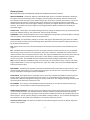
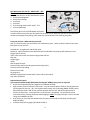
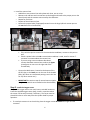
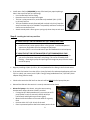
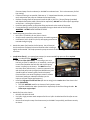
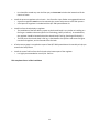
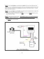
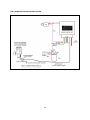
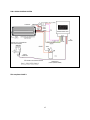
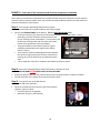
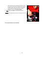
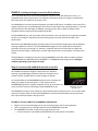
QUICK FUEL TECHNOLOGY® Qfi™ Electronic Fuel Injection System Installation and Instruction Manual INTRODUCTION Your new Quick Fuel Technology® Qfi™ electronic fuel injection system is one of the industry’s most advanced and flexible EFI packages available. It is designed for V6 and V8 street engines up to 500 cubic inches, and delivering from 250 to 525 horsepower. Quick Fuel Technology’s Qfi system allows you to use both the handheld controller or a PC laptop to tune the system. The handheld controller is designed to set up the system and to provide the ability to make the majority of tuning changes to suit your engine. The DASHBOARD program on the DVD allows you to use your laptop to make finer adjustments. It will allow you to become more familiar with how the system operates, and is excellent for advanced or tuning professionals to allow the engine to reach its full potential. It also has the distinct advantage of being compatible with power adder technologies -- nitrous oxide, superchargers and turbochargers, as well as dual throttle body installation. The Qfi throttle body is designed for square flange (4150 and 4500 flange) intake manifolds. Your Qfi throttle body will use a throttle cable linkage designed for square-bore carburetors. In this Installation/Instruction manual, you will be presented with The components included with the Qfi system The required tools to install the system A list of suggested or required parts for the installation/operation Instructions for keeping the Qfi system operating at peak efficiency Please note: The Quick Fuel Technology Qfi electronic fuel injection system is NOT designed for use in the following applications: Methanol/Ethanol (alcohol) fuel (Exception - E85 fuel) Diesel engines Rotary engines Odd-fire V6 engines CAUTION: Use of leaded gasoline will shorten the life of the oxygen sensor 1 Glossary of terms Below are terms that are frequently used in this installation/instruction manual. ADAPTIVE LEARNING - This feature utilizes the wide band oxygen sensor in the exhaust downpipe to determine the engine’s real-time air/fuel (A/F) ratio. The Engine Control Unit (ECU) will instantly make the necessary fuel input changes to keep the engine on the desired air/fuel ratio, all the time, and under all conditions. In short, the “Adaptive Learning” feature is constantly making minor adjustments to maintain the optimum relationship between the fuel and air fed into the engine, allowing it to operate at its highest efficiency for power and/or fuel economy. At the initial start-up, the engine uses the Targeted Air/Fuel Ratio (see below for more details) to control the engine. CLOSED LOOP - “Closed loop” is the default setting for the ECU, making the "Adaptive Learning" feature functional. To shut off "Adaptive Learning,” the "Closed Loop" feature must be cancelled. DASHBOARD - This is the laptop software that is on the supplied disc. This provides you with the ability to infinitely tailor your system. It also contains features for advanced tuners. DATA LOGGING - The Qfi software package can record a wide range of data while driving the vehicle. This allows you to see a timeline of what has occurred during vehicle operation. This feature requires a laptop (not a Mac) to be connected use this function. ECU - Engine Control Unit. This is the small computer that controls the flow of fuel from the throttle body to the engine. kPa - The abbreviation for kilopascals, the metric term used to measure vacuum and pressure. You are probably used to seeing "inches of vacuum" and "pounds per square inch" of pressure. Kilopascals are used because the measure terms for vacuum and pressure are the same. The range of 0-100 kPa covers the vacuum part of the scale while 100 and up is the pressure portion of the scale. In other words, a reading of 100 kPa is zero inches of vacuum and zero PSI. The handheld controller software show the kPa reading as the dominant number. MAP - This term describes two different things. For more clarity, we use the lower case for “map” to refer to the program which details or “maps” the engine functions. Upper case "MAP" refers to the term Manifold Absolute Pressure (measured in kPa). MAP SENSOR - The MAP Sensor provides instantaneous manifold pressure information (in kPa) to the ECU. This is used to calculate the air density, in turn determining the engine's air mass flow rate. This controls, through the ECU, the required fuel metering for optimum combustion. PULSE WIDTH - Pulse Width refers to the length of time, measured in milliseconds (1/1000 or 0.001 second), the injector nozzle is open and injecting fuel into the airstream. It is controlled by the ECU mounted on the QFI throttle body. While this setting can be changed, it normally is left alone. The “Adaptive Learning” feature controls the pulse width to control the optimum A/F ratio. SET UP MENU - This is the part of the Dashboard software that allows you to customize the base map for your specific engine. This includes the Volumetric Efficiency (VE) tables. TARGETED AIR/FUEL RATIO - This is the initial map installed on the computer after answering the set up questions on the hand held controller. This establishes what the computer believes is the ideal air/fuel ratio for the best performance. The "Adaptive Learning" feature of the QFI system modifies the real-time Air/Fuel Ratio (A/F) as the vehicle is driven. This A/F ratio may change at various RPMs or driving conditions. This is a distinct advantage over the carburetor or an EFI system which attempts to run a fixed A/F ratio all of the time. Volumetric Efficiency (VE) - This refers to the efficiency with which the engine can move the fuel/air charge into and out of the cylinders. 2 BEFORE YOU START -- READ THIS FIRST The Quick Fuel Technology Qfi electronic fuel injection system comes from our factory with a handheld controller that allows the user to answer a series of set up questions about the engine and the vehicle, which will produce a basic program for the ECU controller (mounted on the throttle body). See page 18 of this instruction manual for more details. In most circumstances, the information that you will input into the handheld controller will allow you to operate the vehicle. If there may be a need to fine tune the system’s programming, the installation DASHBOARD DVD software disc packaged with this kit will allow you to manipulate the ECU’s programming. This requires a PC laptop computer with Windows XP, Vista, Windows 7, or Windows 8/8.1 operating system. It will not operate on an Apple MAC laptop. When you are answering the questions in the Setup window of the handheld controller, you will be allowing the Qfi’s ECU to match your engine’s specifications. Vented Fuel Tank -- A well-vented fuel tank is REQUIRED for the Qfi system, and a vented fuel cap is NOT sufficient. On page 8, you will see the steps needed to provide an adequate vent, and the need to install a return fuel line. Air filter clearance -- If you are replacing a square flange carburetor, and there is no hood interference with the current air filter, this filter assembly should not have clearance issues. If you are replacing a Quadrajet or other spread bore carburetor (which requires a square flange adapter), a hood clearance problem might occur. This should be evaluated prior to installation. Quick Fuel Technology Qfi System Parts List Please take a moment to review this parts list and the photo to familiarize you with all of the parts included. If a component is missing from the packaging, contact us immediately! QFT 500 System - BASE KIT -- QFT-500BD 1. Throttle body with injectors (500S (Polished) OR 500BD (Black Diamond)) 2. Wide-band O2 sensor 3. ECU wiring harness 4. Throttle body wiring harness 5. O2 sensor bung, gasket, clamps 6. ECU - Engine Control Unit 7. Laptop connector cable 8. QFI Hand Held controller & case 9. Fuel Inlet Kit 10. Data Kit - Qfi Software & Instructions DVD 11. Hardware package -- Fasteners, gaskets, etc. 12. Printed Installation/User manual 3 QFT 500 System with fuel kit - MASTER KIT -- QFT500BDM 1. All of the above in the QFT 500 Base Kit system 2. Fuel Pressure Regulator 3. Fuel Pressure Gauge 4. Fuel Pump 5. Fuel Filter 6. Fuel Line (high pressure EFI rated) - 15 ft. 7. Fuel line AN fittings The Qfi fuel pump in the Qfi 500 Master Kit System includes a 100 micron screen pre-filter built into the pump (It is a white filter you can see just below the threads of the pump’s Inlet fitting), which keeps the coarse particles from reaching the pump. From your tool box…What tools do you need? Here is a list of the tools you will need for the installation project. These are basic hand tools you most likely have in your tool box. Screwdrivers: Straight blade and Phillips head Wrenches: Open/Closed box-end, Ratchet/Socket set advisable but optional, HEX-head wrench set, Oxygen Sensor wrench 3/8 in. electric drill with assortment of high speed drill bits Hole saw Soldering gun Solder Wire Stripper/Crimper Assorted crimp-style wire ends (open end and loop styles) Electrical shrink wrap tubing Black electrical tape 14 gauge wire Medium strength (blue) thread sealer (Loctite 242 or equivalent) Anti-Seize Compound Required optional parts: If you have purchased the Qfi 500 System Base Kit (QFT-500BD), these parts are required. An EFI-rated adjustable pressure regulator (QFT Model 50-5016). High pressure continuous duty EFI fuel pump -- must be rated to deliver 40-45 psi and 45 gallons per minute (gpm/255 liters/hr - lph). We recommend the Quick Fuel Technology Model 50-5011 pump. (We also recommend a 100 micron pre-filter between the fuel tank and the fuel pump inlet to protect the fuel pump. A sock-type filter in the fuel tank is acceptable. The pre-filter prevents coarse debris from entering the pump and damaging it.) HINT: The higher the filter’s micron number rating, the COARSER the filter. A 10 micron (or finer) fuel filter between the fuel pump and the Qfi throttle body assembly (QFT Model 50-5015). A 100 psi fuel pressure gauge (QFT Model 50-5012). 4 15 ft of 3/8” (0.375” - 9.5 mm)/-06 AN high pressure rated fuel line (reinforced rubber or braided stainless steel) If engine is equipped with a spread-bore carburetor (such as a Quadrajet, ThermoQuad, Carter AFB or Edelbrock) and you do not wish to change manifolds, an adapter to accept the square flange throttle body is required. PHASE I: Install the throttle body assembly, plumbing and other mechanical components Step 1: Preparation & disassembly of fuel system on the engine Disconnect battery cables. Since you are dealing with the fuel and electrical system in this installation, this step MUST be performed. o Disconnect plumbing (fuel and vacuum) from the carburetor o Drain the fuel lines into a fuel safe container o Mark the vacuum lines for relocation on throttle body. (See Page 6 for details). o Remove the carburetor, avoiding tipping the carburetor and spilling fuel o After removal, drain the float bowls into the fuel safe container o Remove the old carburetor to intake gasket. If you are replacing a large square flange carburetor (Holley 4500, King Demon), you will need a transition spacer. Use QFT part number 300-4145-1AL. If replacing a spread-bore carburetor, install an adapter plate to convert to a square flange, installing a new spread bore carburetor gasket below the adapter, and placing a new square flange carburetor gasket on the top of the adapter plate. Install throttle body to intake (NOTE: This may require new, longer carburetor studs) o Connect the throttle linkage and the throttle return spring. If replacing a square bore carburetor, the existing throttle linkage/spring assembly can be used. If replacing a spread bore style carburetor, a new assembly must be purchased. (We suggest QFT p/n 49-3 Throttle Return Kit. Available at leading performance retailers) o Mount with nuts and lock washers (provided), and tighten. DO NOT over tighten. Remove the old temperature sensor and install the provided 3/8-NPT Coolant Temperature Sensor into the intake manifold coolant port, as close as possible to the thermostat. (This may require a reducer bushing.) o Connect the Green/Black wiring harness from the throttle body to the coolant temperature sensor. See Service Parts list on page 30 should the temperature sensor require replacement in the future. 5 Install the vacuum lines o ALWAYS use new vacuum line and replace each hose, one at a time o Measure each old hose and cut new hose to that length and install to the proper port on the throttle body and the vacuum source used by the carburetor o Repeat for each hose o Dispose of the old vacuum lines o Connect the power brake (if equipped) vacuum line to the large 3/8-inch vacuum port on the rear base of the throttle body. If the vehicle requires vacuum for the transmission modulator, connect to this port as well. If both a power brake unit and a transmission modulator is used, install a vacuum Tconnector to accommodate the vacuum lines If you are using a vacuum advance distributor, connect distributor vacuum line to either the upper (timed) port on rear or on the right side of the throttle body o Connect the MAP sensor, located on the bottom of the QFI ECU box, to the lower port on the rear of the throttle body. (QFT does not recommend putting a tee in this line for any other vacuum use.) o IMPORTANT Be certain to cap all unused vacuum nipples, using the caps which were installed on the throttle body Step 2: Install the Oxygen sensor If no previous oxygen sensor was used, locate a suitable location to install the supplied oxygen sensor bung. Install in a position where the sensor can be easily serviced, if necessary. The sensor must be placed 20 inches or more away from the cylinder head for proper operation. If a catalytic converter is on the vehicle, place the oxygen sensor BETWEEN the engine and the converter 6 For stock, cast iron manifolds, the location should be just past where the exhaust pipe connects to the exhaust manifold. If headers are used, make sure it is about 4-6 inches past the collector pipe o Install to the exhaust pipe (not into a header tube or the collectors VERY IMPORTANT On both stock manifolds and headers, the sensor should be mounted between the 9 and 3 o’clock position and at least 10° above horizontal (wire side up, sensor tip down). This prevents condensation, exhaust debris from collecting in the sensor and contaminating it, as well as possible road damage. Again, always think about placing the sensor where it can be serviced the most easily. Drill a 5/8-inch hole in the exhaust pipe Using stainless steel worm gear clamps OR weld (PREFERRED) the bung in place on the exhaust downpipe (This may require installation at a welding or muffler shop) Using an O2 sensor installation wrench, install the oxygen sensor in the bung. Carefully apply antiseize compound to the threads before installing, be certain to apply ONLY to the threads, not to the sensor. Plug the harness cable from the throttle body into the cable from the Oxygen Sensor. Using cable ties, keep harness away from the exhaust system and/or moving parts. See Service Parts list on page 30 should the Oxygen sensor require replacement in the future. 7 Step 3: Install the fuel system Review the diagram below to understand the installation of the major components of the fuel delivery system. The installation of the fuel system starts with the fuel tank. Drain the fuel tank and remove it according the vehicle maker’s instructions. NOTE -- ALL fuel tank work MUST be done with a dry tank, with no fumes in the tank! Any fuel tank welding should be done by a professional welder!! Clean the interior of the tank, since debris in the fuel is an enemy of any EFI system If not present, install a free-flowing vent in top of tank (REQUIRED). The vent should be a MINIMUM of a ¼-in. (0.250 in/6 mm) diameter. A vented filler cap is not adequate for this system. o The vent tube should have no kinks, with the opening pointed to the top of the tank (upside down “U”) to minimize debris from entering the tank. 8 Install return fuel line (REQUIRED) to top of fuel tank (may require placing a hole in the top of the tank to install bung). o Use a barbed-style fuel line fitting o Route the return line to top of the engine o This line is a low pressure line, and needs only standard 3/8 in. (0.375 in./10 mm) fuel line o This line should be securely fastened (with no slack in the line), keep line away from heat source (or shielded if not possible) and fasten securely to chassis next to the floor pan. o Attach securely with a worm-gear or spring style hose clamp at each end Step 4: Installing the Fuel Pump and filter IF USING THE QFT 500 SYSTEM BASE KIT (QFT-500BD) READ THIS! Install a sock (or) screen type pre-filter in the gas tank. It will be adequate to capture any large debris that can damage the fuel pump. The other option is an in-line 100 micron pre-filter between the tank and pump IF USING THE QFT 500 SYSTEM MASTER KIT (QFT-500BDM) READ THIS! The fuel pump has a 100 micron pre-filter built into the pump (It is a white filter you can see just below the pump’s Inlet fitting). This can be cleaned by back flushing -- removing the pump and pouring fuel through the pump from the outlet end of the pump. Begin by installing a 3/8 in. (0.375 in. /9.5 mm) barbed fuel line fitting in the fuel tank outlet. If the tank’s fuel outlet is less than 3/8 in. (many fuel tanks for carbureted applications will have 5/16 in. outlet), you must a install a 3/8 in. bung (If using braided steel line, a 3/8” NPT/-6 AN adapter fitting must be used) Check to be certain the fuel line from the tank will be ABOVE the fuel pump inlet port Reinstall the fuel tank. Be certain it is securely mounted to the chassis Mount fuel pump to the chassis, using the two mounting brackets with rubber vibration isolators provided. o If using the QFT 500 System Base Kit, you must use an EFI pump (either in-tank or external) rated for 40-45 psi (continuous) and 45 gallons per minute (gpm). o Mount below the bottom of the tank outlet for a gravity feed o Position within 2-3 ft. (61-91 cm) of the tank o Place in protected position above the lowest portion of the 9 o o o o frame and away from the exhaust (or shielded from exhaust heat. This is also necessary for fuel line routing) If frame mounting is not possible, fabricate an “L” shaped metal bracket, and mount close to tank, and position the pump at or below the fuel tank outlet. Remove the plugs from the pump and install the 3/8 in. (0.375 in. /10 mm) fittings (provided) with blue thread locker sealer (Loctite 242 or equivalent). DO NOT use Teflon tape or pipe dope on fuel lines -- will clog fuel injectors!! Install the sealing washer on the outlet fitting and attach to the outlet of the pump If using AN fittings, use 3/8” NPT/-6 AN adapter fittings at both ends of the fuel pump WARNING -- DO NOT OVER TIGHTEN FITTINGS! Install fuel pump ground line to the chassis. o Drill 5/32 in. (0.15625 in/4 mm) hole in chassis o Scrape area to expose bare metal (assures an excellent ground) o Install with 3/16 in. (0.1875 in/4 mm) self-tapping metal screw inserted through ring lug Attach the power (hot) lead to the fuel pump. Use of electrical shrink wrap over the pump’s electrical terminals after installing is highly recommended. This helps protect the pump terminals on the hot and ground sides from corrosion. Install inline filter(s) -- pre-pump (low pressure) is recommended/high pressure filter required (NOTE: A carburetor filter CANNOT be used) o In-line Pre-Filter (OPTIONAL) -- If choosing to use an inline fuel pre-filter (in addition to, or instead of, a sock-type in-tank filter) between the fuel tank and the fuel pump, mount it securely to the chassis. This MUST be a lowrestriction filter (100 microns). It must be mounted in line with the fuel pump inlet (or higher but NEVER lower), and should be able to maintain gravity feed to the pump. (Incorrect filters can cause the pump to create a vacuum and aerate, leading to reduced fuel delivery to the injectors and poor engine performance.) o Install the high pressure EFI fuel filter (10 micron rating) on the outlet side of the electric fuel pump (REQUIRED) This filter MUST BE rated for an electronic fuel injection system Use blue thread locker sealer (Loctite 242 or equivalent) on the filter fittings threads. No Teflon tape or pipe dope! Attach fuel line to the chassis o DO NOT USE OLD FUEL LINE o Use 3/8 in. high pressure rated neoprene fuel line or 3/8 in. braided steel fuel line (Do not use solid line) o Be certain to keep line away from heat source (or shielded if not possible), and fasten securely to chassis. 10 o Line should be routed very near the floor pan, and must not be below the lowest level of the chassis or frame. Install the pressure regulator to the chassis -- the fire wall or inner fender are suggested locations o A pressure regulator must be used to maintain the correct fuel pressure to the fuel injectors o A fuel pressure regulator is included with the QFT 500 System Master Kit Install line from throttle body to regulator o The installation of the fuel delivery system to the throttle body is very similar to installing to a fuel log to a modular carburetor (Quick Fuel Technology, Holley or Demon). As noted earlier, the regulator should be located behind the throttle body's fuel log. (See Page 8 for details). o The fuel enters the throttle body’s fuel log, is distributed to the injectors and excess fuel goes into the fuel regulator, and is returned to the fuel tank. A fuel pressure gauge is a supplied as a part of the QFT 500 System Master Kit assembly to help you monitor the fuel pressure Install the return fuel line from the fuel tank to the bottom port of the regulator o It is highly recommended to use a 3/8 in. fuel line This completes Phase I of the installation 11 PHASE II: Install wiring harness into vehicle wiring The next phase of the installation process for the Qfi system is connecting the components you have previously installed to the vehicle’s electrical system. Thanks to the Qfi wiring sub-harness, this process should be relatively simple. The Qfi system wiring harness has an 8-pin watertight electrical connecter with eight wire leads attached. You will need to have additional wire and connectors to connect four of these wires to their appropriate connections. It is important to be certain the wires you are connecting to the sub-harness leads are the same gauge. Soldering the appropriate wire on the harness to its correct location, and protecting the connection with heat shrink tubing is highly recommended for making these connections. While crimp-style butt connectors may work, they can often make poor connections and may not make a good connection that will maintain the proper electrical flow to the system. The main wiring harness has 11 leads, which are clearly labeled. In case the labels come off, the colors are as follows: *Heavy gauge Red -- BAT POSITIVE – 16 gauge – to Battery positive ( + ) terminal * Black/Black 2 Harness w/ loop connector – Ground to ( - ) battery terminal *Yellow – FUEL PUMP POS – 18 gauge – to ( + ) RED terminal on fuel pump *Pink -- KEY POS – 20 gauge – to the Ignition Key/Crank terminal **Green – Tach In – 20 gauge – HEI/Ready to Run Distributor, Ignition coil ( - ) terminal; Tach output of CDI/MSD box on a No-Points distributor (either magnetic pick up or crank trigger wheel) **Brown w/ female spade connector – 20 gauge – Coil Drive. (If using timing control feature). **Orange – 20 gauge – Fan 1 NOTE: These wires supply ground when active. Relay required. **White – 20 gauge – Fan 2 **Green/Violet 2 wire harness – To Locked Distributor. (If using timing control feature). *Black/Pink – 2 wire harness – To HANDHELD *Black/Orange/Green/Grey/Blue – 5-wire plug harness – Oxygen Sensor **Brown/Pink/Grey – Fuel Pressure Gauge (Optional) * THESE MUST BE CONNECTED IN ALL IGNITION APPLICATIONS!! ** These may or may not be used NOTE: The Qfi system CANNOT be used with a basic, points distributor ignition system. Depending upon the ignition system, there may be one or more wire leads that are not used, which should have the ends sealed with electrical tape then doubled over and sealed with heat shrink tubing. The extra leads should be coiled up and secured with cable ties. The extra leads should not be cut off, in case you decide to use a different type of ignition system in the future. Step 1: Connect the RED (16 ga.), 12V fused wire directly to the positive battery cable (disconnected). 12 Step 2: Connect the YELLOW wire marked with the “PUMP” label to the positive (RED) side of the electric fuel pump. The GROUND wire will attach to the frame and the negative (BLUE) terminal on the pump. (If using the existing fuel pump, disconnect the previously installed power feed to it. The new QFI ECU will control the pump.) Step 3: Connect the PINK wire marked “KEY” to the power source that supplies battery voltage when the key is in the “On” position and the “Crank” position. Be certain the voltage to the PINK ignition wire MUST see 12 volts, and NEVER fall below 9.5 volts when cranking the engine. Step 4: Connecting to the ignition system -- READ CAREFULLY! Refer to the wiring diagrams below for the BASIC WIRING DIAGRAM (Figure 1), and four popular ignition system applications. Begin the wiring of the ignition system by referring to Figure 1 (below). All ignition system options will REQUIRE these to be connected. 13 FOR HEI and READY-TO-RUN (RTR) DISTRIBUTOR NOTE: GREEN ARROW – Some Ready-to-Run (RTR) distributors may not have a TACH OUT wire to connect to the GREEN wire. In those cases, install the GREEN (DOTTED LINE) wire to the coil’s NEGATIVE ( - ) terminal. NOTICE: If you use a CD Ignition box with a HEI (or Ready-To-Run) distributor connecting the GREEN wire to the (-) terminal on the coil will cause FAILURE of the Engine Control Unit (ECU)! 14 FOR A NON-COMPUTER TIMING CONTROLLED IGNITION SYSTEM 15 FOR A COMPUTER TIMING CONTROL SYSTEM 16 FOR A SPARK CONTROL SYSTEM This completes PHASE II 17 PHASE III: Final steps of the mechanical and electrical components installation At this point, the mechanical components are installed, and the electrical connections into the vehicle’s electrical system have been made. Now, you will take the steps needed to connect the mechanical and electrical components to the battery. Step 1: Assure proper grounding of the electrical system Be certain the battery is in good condition, and is fully charged Connect the GROUND CABLE to the battery. This is a VERY IMPORTANT issue o To function correctly, the electrical circuit must be complete back to the battery. A poor grounding circuit will choke the power/hot side of the circuit, resulting in poor performance. In many cases, lack of attention to the ground side of an electrical system causes many automotive electrical problems. o The ground cable from the battery must be in good condition and attached to the engine block and the vehicle’s chassis o There must be auxiliary braided ground straps between the vehicle’s engine and chassis. If these are broken or missing, they can be obtained at any automotive parts store. o This is especially critical for a computer controlled fuel injection system Step 2: Reconnect red (HOT) battery cable to the battery’s positive terminal THIS MUST BE DONE AFTER INSTALLING THE GROUND CABLE As with the ground cable, the red, positive cable must be in good condition. Replace if needed. The red (hot) cable is the lifeline of the entire electrical system Step 3: Turn ignition key to the ON position. Check for fuel pump operation Check for possible leaks from the fuel tank to the pressure regulator, repair any leaks o Check fuel pressure at regulator o Should be 42-45 psi (290-310 kPa) 18 o Should the fuel pressure exceed 45 psi/310 kPa, loosen the jam nut on the top of the regulator and using a hextype Allen wrench, back off the adjuster screw slightly and until the fuel pressure gauge reads correctly. Retighten the jam nut. Do not over tighten. NOTE: The engine IS NOT to be started at this point!! Step 4: After checking fuel pressure, turn the ignition key OFF This completes PHASE III of the installation 19 PHASE IV: Installing the Engine Control Unit (ECU) software This is the phase where you use the Qfi HANDHELD controller, which will allow you to enter, in a straightforward, step-by-step manner, the important information about your engine to establish the base tune-up for the vehicle on the system’s ECU. The HANDHELD is the initial connection between you and the Qfi System. In addition to the entry of the engine’s specifics, you are establishing the basics for the initial engine start up and operation. From that point forward, the ECU will begin its Adaptive Learning process, and a number of aspects of this procedure can be monitored on the handheld controller. The Qfi HANDHELD unit, with the proper input information in the vast majority of installations will adapt the ECU to your engine’s parameters and your driving style to provide excellent drivability and performance. Because the Qfi HANDHELD programs the ECU with the correct baseline engine data, and the Adaptive Learning capabilities of the ECU, the Qfi DASHBOARD program for your laptop will be used almost exclusively to do very fine tuning. It is, however, a powerful tool that can help teach you about the features of the Qfi System, and allow you to make slight adjustments to the program, and observe the results. The Qfi software is installed into the ECU using the HANDHELD controller and/or a laptop computer using WINDOWS XP, WINDOWS VISTA, WINDOWS 7, or WINDOWS 8 operating systems. (An Apple computer/operating system cannot be used). Step 1: Connect the Qfi HANDHELD Controller to the ECU At this point, the HANDHELD Controller will provide the Qfi system with the needed information to begin the process we call “Adaptive Learning” by establishing the baseline values for the engine and a number of other variables the ECU needs to begin to operate. As mentioned above, the DASHBOARD program on the computer will allow you to begin to fine tuning later. If you need to use the DASHBOARD program for a laptop computer, the set up instructions are at the end of this section, following the initial HANDHELD set-up. HANDHELD Controller Opening Screen The HANDHELD connects to the vehicle by a data communications cable that uses a 2.5 mm male audio jack-type connector from the side of the HANDHELD to connect to female audio jack-type connector that is part of the QFI System’s wiring harness. SETTING UP THE ECU USING THE Qfi HANDHELD CONTROLLER Plug the 2.5 mm male data plug into the 2.5 mm female plug in the ECU wiring harness. Turn on the ignition key to energize the ECU and the HANDHELD Controller The HANDHELD Controller screen will show the opening screen o Use the Controller’s UP, DOWN and ENTER button to select menus and answers 20 If the HANDHELD displays a “COMM ERROR” message, see if the HANDHELD’s communication cable is connected, and that the ECU is powered on. Then press the RESET button on the HANDHELD. STEP 2 - BEGIN SETUP 1. Using the UP/DOWN controller buttons, select “Initial Setup” and press “Enter” 2. You will begin to enter the engine’s basic parameters into the ECU’s memory 3. Once you enter these it into the ECU memory, you can edit them later using the “Advanced Setup” menu or with the DASHBOARD program 4. Enter the engine’s displacement (cubic inches) 5. Enter the number of cylinders For the Qfi system this will be either 6 or 8 6. Enter number of injectors For the Qfi system, enter 4 21 HANDHELD Controller 7. Enter size of injectors For the Qfi system, the injectors are rated at 66 lbs. of fuel/hr, enter 66 8. Enter the camshaft type. There are several menu options here that cover a range of cam specifications. Select the cam spec that fits your engine. 1= Stock Cam 2= Performance Cam 3= Race Cam 4= Custom Grind Cam -- The Custom Grind Cam option will REQUIRE the use of the DASHBOARD program on a PC laptop to provide the necessary configuration. Please see page 28 for details. 9. Enter source of engine speed data (RPM Input). This can be from a rotor-style distributor, or from an electronic distributor. There are two menu choices RTR Distr. (Rotor-type, Ready to Run distributor) = 0; 2-wire (electronic distributor) = 1. NOTE: RTR = No Timing Control; 2-wire = Timing Control 10. The next inputs will be for the air-fuel mixture targets at 4 points of engine operation. For the initial HANDHELD setup procedure, all will be entered with an initial value of 12.8. The target screens will be (in order): AF Idle Target - Set at 13.5 AF Off-Idle Target - Set at 13.0 AF Cruise Low Target - Set at 13.8 AF Cruise High Target – Set at 14.0 22 11. Enter the air-fuel mixture ratio at Wide Open Throttle (WOT). The initial setting will be 12.7. The next step of the initial HANDHELD set-up will be to set the engine Idle Target RPM. The initial setting is 800 RPM. This concludes the initial phase of the Qfi HANDHELD controller setup. The next stage will be setting the engine’s timing for SPARK CONTROL IGNITION SYSTEMS - i.e. MSD and other capacitive discharge ignition CDI - systems. STEP 3 - SETUP ENGINE TIMING 1. Return to the HANDHELD Controller’s HOME SCREEN, and select “Timing Setup” 2. The first screen will be for Max Advance RPM. Set at 3000 RPM, or your desired total RPM setting. 3. Set the desired Idle Timing (Initial Timing). Example: 15.0 (degrees). 23 4. Set the Total Timing Advance. Set at 30.0 (degrees). NOTE: 36° Total timing is maximum on a small cap distributor. 5. Set the rev limiter. Set for 6000 rpm. This completes the initial setting of the engine’s timing. If you are planning to use the HANDHELD Controller to make adjustments while driving, be smart and have a friend with you to either drive or operate the HANDHELD Controller! Step 4: Start vehicle Turn the key to ON position. Listen to pump -- it should shut down after 2-3 seconds Check for leaks (again), repair if needed Start the engine. The engine will idle high until target temperature is achieved. Do not adjust until temperature reaches approximately 180° F (82° C), unless RPM is unsafe to engine. Adjust fuel pressure to 45 psi (310 kPa) When engine temperature reaches 180° F (82° C), adjust idle screw up or down until the IAC value on the handheld controller stabilizes at between 40–50. Take note to see that the TPS value is 1, if not, turn key off and back on to reset TPS. The TPS selflearns to value 1. NOTE: Do not touch accelerator pedal while starting. See that Target RPM and Actual RPM match, as well as, Target AF, and Actual AF. If you have made a mistake in SETUP or ADVANCED SETUP, go to the CAM Type window (Step 8 in the SETUP Menu), change the setting to ANY different cam then the one you selected, PRESS ENTER, then turn the ignition key OFF to save. Wait until the red light on the front of the ECU goes off. Turn the key back ON, go back to the desired cam, enter it, and the system will revert to the factory default setting. Next, proceed to the window that had the incorrect value entered, enter the correct value, and finish the setup. 24 Step 5: SETUP ADVANCED SETTINGS The final step will use the Advanced Setup screens on the HANDHELD. These screens are designed to provide fine tuning of the Qfi ECU. They provide identical inputs as entering them into the system with the laptop DASHBOARD program. Each screen value pictured is the factory default setting. Advanced setup opening screen Fan 1 -- Temperature at which FAN 1 comes on. FAN 1 will turn off when the temperature is 5 degrees lower than the ON temperature. The temperature is in Fahrenheit. NOTE: If there is no electric fan, this will not be used. Fan 2 – Temperature at which FAN 2 comes on. This is an AUXILIARY FAN. FAN 2 will turn off when the temperature is 5 degrees lower than the ON temperature. The temperature is in Fahrenheit. NOTE: If there is no electric fan or no auxiliary fan, this will not be used. Fuel Prime Cold – Amount of fuel used to prepare the Qfi System for low engine temperature starts. The range is 0-200. Fuel Prime Warm – Amount of fuel used to prepare the Qfi System for warm engine temperature starts. The range is 0-200. 25 Crank Fuel Cold – Amount of cranking fuel at low engine temperatures. Range is 0-30. Crank Fuel Warm – Amount of cranking fuel at warm engine temperatures. Range is 0-30. Crank Fuel Hot – Amount of cranking fuel at high engine temperatures. Range is 0-30. Enrichment Fuel Cold – Percent of fuel added at low engine temperatures. Range is 0-99% Enrichment Fuel Warm – Percent of fuel added at medium engine temperatures. Range is 0-99% 26 Enrichment Fuel Hot – Percent of fuel added at high engine temperatures. Range is 0-99% Accel Enrich Slow – Acceleration enrichment slow change TPS (Throttle Position Sensor) input. Range is 0-40. Accel Enrich Fast – Acceleration enrichment fast change TPS (Throttle Position Sensor) input. Range is 0-40. Decel RPM – Engine RPM upper limit. If this is exceeded, the ECU to go into the fuel cutoff mode, stopping fuel delivery. CL On-Off – Turn the Closed Loop function On or Off. FACTORY DEFAULT IS “ON” – it is highly recommended to keep this function ON for the best performance from the QFI System! 27 ADL – Adaptive learning feature On or Off. FACTORY DEFAULT IS “ON” – it is highly recommended to keep this function ON for the best performance from the QFI System! Step 6: Using the QFI DASHBOARD software to connect the PC laptop to the QFI ECU As mentioned above, the DASHBOARD software works with WINDOWS XP, WINDOWS VISTA, WINDOWS 7, or WINDOWS 8 operating systems, but not with an Apple laptop. Perhaps 90-95% of the tuning of the ECU will be done by the Qfi HANDHELD. The data entered into the ECU with the HANDHELD can be adjusted using the HANDHELD, and will not require the use of the DASHBOARD program on the laptop. Insert supplied DVD into laptop’s CD/DVD player The software will start automatically. If it does not -- go to My Computer (WINDOWS 7 or 8), double click the CD/DVD Drive icon o The installation window should pop up on the screen, and the installation procedure will continue Open the DASHBOARD software program on the laptop Once the installation of the DASHBOARD program is complete, you can begin to use the laptop with the Qfi system. The home screen for the DASHBOARD program is designed to look like a digital dashboard. It provides a real-time look at the engine’s operation -- important information about the behavior of the fuel injection system and the environmental data influencing its performance. Connect the laptop to the Qfi throttle body wiring harness with supplied USB/male 2.5 mm audiotype jack cable into the female 2.5 mm audio jack-type connector used with the HANDHELD controller. NOTE: A DB9 Serial Adapter to USB Cable and accompanying software may be required. Turn the ignition key to “ON” (DO NOT start the vehicle) Open the QFI DASHBOARD program o With the key ON and the engine NOT running, you can adjust settings o From the SETUP TAB, select the MAIN SETUP from the Drop-Down menu This will show all of the settings you have seen and made on the HANDHELD device. A unique feature is the ability to HOVER the mouse icon over the topic description, or the cell description, and see additional information about the definition and function 28 Start the engine o With the engine RUNNING, you can observe the engine’s parameters in real time by selecting the VIEW TAB at the top of the page, and select ECU Real-Time o You will see some numbers remaining constant, others will change o These numbers will change as engine rpm increase/decrease, as engine loads vary, etc. Adjusting the profile to the vehicle The most common use of the DASHBOARD program will be in the case of a CUSTOM GRIND CAM. Because the cam specs may be significantly different than stock, performance or race type cam. To establish a map for the cam, use these steps below: o o o o o o Open the DASHBOARD program on the laptop Select tab marked “Select” Choose VE Table (“VE” = Volumetric Efficiency) From popup box, choose VE #4 button Close popup box Choose the VE Table tab Be sure VE Table #4 appears in the right side, lower corner of the VE Table Modify the VE table values as needed For additional assistance in setting up the VE Table, and other areas of the DASHBOARD, we advise you to consult with a professional EFI tuner. ___________________________________________________________________________________ While we have tried to make this installation guide/instruction manual easy to understand and follow, we realize that you may have questions. Please contact the Quick Fuel Technology Technical Service Department. We are available at 270-793-0900, Monday-Friday, 8:00 AM to 5:00 PM Central Time to assist you. 29 Qfi REPLACEMENT PART INTERCHANGES These parts will interchange with the Qfi components Throttle Position Sensor Application: 91-95 Chevy/GMC C1500 V8 TBI Quick Fuel Qfi 50-5007 General Motors 17106681 Standard Motor Products TH51T OEM 9959 AirTex/Wells 5S5008 Delphi SS10459 AC-Delco 213-3895 Idle Air Control Motor* Quick Fuel Qfi General Motors Application: 99-03 GM LS-1 50-5006 17113598 Coolant Temperature Quick Fuel Qfi General Motors Standard Motor Products OEM AirTex/Wells Delphi AC-Delco 85-07 Chevrolet (All) 50-5008 15326386 TX3T 8296 5S1018 TS10075 213-928 Oxygen Sensor Quick Fuel Qfi Bosch - Std length Bosch - Long length Volkswagen- Std length Volkswagen- Long length Standard Motor Products Std length Standard Motor Products Long length AirTex/Wells - Std length AirTex/Wells - Long length Delphi- Std length Delphi- Long length AC-Delco- Std length AC-Delco- Long length Denso- Std length Denso- Long length Air Charge Temp Sensor Quick Fuel Qfi 50-5009 17014 17090 021-906-262B 068-906-265D SG897 SG1175 5S4265 5S4260 ES10921 ES10922 213-3894 213-3895 2345117 2345111 50-5005 30 General Motors Fuel Pressure Regulator Quick Fuel Qfi 33004280 50-5016 Fuel Pump Quick Fuel Qfi 50-5011 Fuel Filter Quick Fuel Qfi 50-5015 Fuel Pressure Gauge 100 psi Quick Fuel QFI 50-5012 * Dependent on Idle Air Control passage size www.quickfueltechnology.com 99-QFI 9/2014 (Rev. 3) 31