1
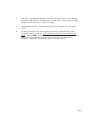
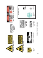
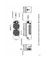
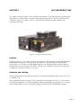
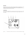
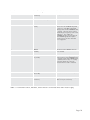
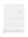
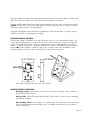
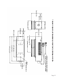
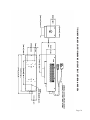
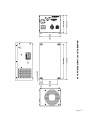
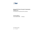
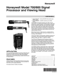
NLC 800 Air-Cooled Argon-ion Laser User’s Manual Complete with Operating Instructions for the 8470 and 2270 Power Supply TABLE OF CONTENTS CHAPTER 1: INTRODUCTION 1 CHAPTER 2: LASER SAFETY CENTER FOR DEVICES AND RADIOLOGICAL HEALTH (CDRH) COMPLIANCE REQUIREMENTS MAINTENANCE REQUIRED TO KEEP THIS LASER PRODUCT IN COMPLIANCE WITH CENTER FOR DEVICES AND RADIOLOGICAL HEALTH (CDRH) REGULATIONS PRECAUTIONS FOR SAFE OPERATION OF CLASS 3b & 4 - MEDIUM & HIGH POWER LASERS PRECAUTIONS FOR SAFE OPERATION OF THE LDI 8470 AND NLC 2270 POWER SUPPLY CDRH CONTROL DRAWINGS 2 3 5 CHAPTER 3: NLC 800 PRODUCT LINE COOLING HANDLING & SHIPPING MOUNTING CONNECTIONS OPTIONAL REMOTE CONTROLLER REMOTE CONTROL OPERATION ENERGIZING THE LASER TURNING OFF THE LASER 800 PRODUCT LINE SPECIFICATIONS 800 PRODUCT LINE DIMENSIONS 8470 POWER SUPPLY DIMENSIONS 8 8 8 9 9 12 12 13 13 14 15 17 CHAPTER 4: TROUBLESHOOTING GUIDE 18 CHAPTER 5: CUSTOMER SERVICE CUSTOMER SERVICE DEPARTMENT WARRANTY INFORMATION RETURNS, ADJUSTMENTS AND SERVICING 19 19 19 20 2 2 3 CHAPTER 1 Features Superior Beam Quality Low Noise Internal Mirror Design Extended Lifetime Designed for Fiber Optic Delivery Exceptional Warranty INTRODUCTION Applications Flow Cytometry DNA Sequencing Confocal Microscopy Spectroscopy Hematology Optical Disk Mastering Lightshows & Displays Basic Research Design The 800 argon laser delivers a full 500mW of output power in multiline/multimode configuration as well as high output powers in the single line options. The 800 also offers improved thermal stability, longer life and low electronic and optical noise. The laser incorporates the latest in internal mirror tube technology assuring permanent beam alignment and eliminating contamination. NLC’s design permits ease of servicing. The laser is also available with a remote cooling option for applications where fan vibration is a concern. Page 1 CHAPTER 2 LASER SAFETY CENTER FOR DEVICES AND RADIOLOGICAL HEALTH (CDRH) COMPLIANCE REQUIREMENTS The following laser component conforms to the safety specifications and performance standards required of Class 3b & 4 lasers as defined by the Center for Devices and Radiological Health (CDRH) -The National Laser Company 800 Series Product Line MAINTENANCE REQUIRED TO KEEP THIS LASER PRODUCT IN COMPLIANCE WITH CENTER FOR DEVICES AND RADIOLOGICAL HEALTH (CDRH) REGULATIONS The NLC 800 product line complies with Title 21 of the United States Code of Federal Regulations, Chapter 1, Subchapter J, Parts 1040.10 and 1040.11, as applicable. To maintain compliance, the operation of all features listed here should be verified annually or whenever the NLC 800 product line is subjected to adverse conditions. 1. Verify the emission indicator on top of the laser head provides a visible signal when the laser emits accessible laser radiation that exceeds the accessible emission limits for Class 1 (0.39mW for continuous-wave operation where output is limited to the 400 to 1400nm range.). 2. Verify the beam attenuator (mechanical shutter) actually blocks exposure to laser radiation. If not, call the National Laser Company Customer Service Department (See Chapter 5) 3. Verify that the laser head has not been modified in any way. Modifications made by an OEM manufacturer to an NLC Laser Head violate compliance with CDRH standards and may also void any warranties. 4. Verify that if the 800AL or 800AM multi-line laser is labeled as a Class 3b laser that it is used only with an 8470-02 (or equivalent) power supply. Page 2 WARNING: The use of controls, adjustments or performance of procedures other than those specified herein may result in hazardous radiation exposure. The NLC 800 product line is a Class 3b & 4 - medium & high power laser whose beam is, by definition, a safety hazard. Avoid viewing the beam directly, or as reflected by a mirror or other polished surface. The 800 product line, when used in conjunction with compatible power supplies contains circuits that operate at dangerous voltages and current levels. Avoid touching high voltage terminals or components. Internal measurements and/or adjustments should be made by qualified personnel only. PRECAUTIONS FOR SAFE OPERATION OF CLASS 3b & 4 - MEDIUM & HIGH POWER LASERS 1. Establish a controlled area for laser operation: limit access to those trained in the principles of laser safety. 2. Post warning signs prominently near entrances to the laser operation area. 3. Set up shields to prevent the beam from escaping the laser operation area. 4. Set up a target to block the beam after it passes through the operating area. 5. Keep the protective cover on the laser head during operation. 6. Enclose the beam path whenever possible. 7. Keep the laser beam either above or below eye level. 8. Do not look at the beam directly or as reflected by a mirror or polished surface. When working with a class 4 laser, do not expose skin to beam. 9. Safety glasses must be worn at all times when working with a class 4 laser. 10. When working with a class 4 laser, contact your laser safety officer for operation of the laser activation warning system. PRECAUTIONS FOR SAFE OPERATION OF THE LDI 8470 AND NLC 2270 POWER SUPPLY 1. In the final installation, the mains primary signals and ELV secondary signals of the “Mains”, “Laser”, and “Interface” connectors on the front panel must be isolated from the operator and accessible by SELV circuits. PRI = Primary Reference (Hazardous) ELV = Extra Low Voltage SELV = Safety Extra Low Voltage Page 3 2. A minimum of an approved method of reinforced or double insulation must be between any primary (PRI) hazardous and any extra low voltage (ELV) or safety extra low voltage (SELV) source at the connectors of the power supply. 3. Supplemental insulation is required between any ELV circuits and any user accessible circuits. 4. The electrical hazards of the power supply are the same as other electrical systems connected to the AC power line. Only a qualified technician should install the power supply. There are NO user serviceable parts within the power supply, therefore the cover of the power supply and any connected component should never be opened, as hazardous voltages may be present after the unit has been turned off. Page 4 Figure 2.1 Standard Safety Warning Labels WARNING!: The energy level of the laser beam is high enough to cause serious damage to the eye with possible loss of vision if the beam were to pass directly into the eye! CDRH CONTROL DRAWINGS The following labels are found on the 800 product line. These labels are important in identifying potential safety hazards and are in conformance to CDRH labeling requirements. Page 5 Page 6 4. Aperture Label 7. Danger Open Cover Class 3b 3. Class 4 Danger 6. Final Q.C. Label 8. CE Mark 9. UL Mark NON-CDRH Labels 3. Class 3b Danger 7. Danger Open Cover Class 4 2. Cover Avoid Exposure NLC 800 PRODUCT LINE LABELS 5. Model & Serial Number 1. CE Warning Labels Class 4 1. CE Warning Labels Class 3b Page 7 NLC 800 PRODUCT LINE (07 COVER CONFIG.) LABEL ILLUSTRATION CHAPTER 3 NLC 800 PRODUCT LINE This chapter contains information on the installation and operation of the National Laser Company (NLC) 800 product line of laser heads. Information regarding the specifications of the NLC 800 product line will also be given in this chapter. Figure 3.1 shows the NLC 800 Laser with the standard cover configuration (07 Fans). Figure 3.1 The NLC 800 Series Laser COOLING The 800 product line is air-cooled. Fans draw cooling air through the openings at each side of the laser head and exhausts warm air vertically through the head cover. As mentioned in the "MOUNTING" section below, you will need to provide adequate space for air intake and exhaust, and must prevent heated exhaust air from returning to the intake. The laser is also available with a remote cooling option for applications where fan vibration is a concern. HANDLING AND SHIPPING When unpacking and carrying any laser head, lift it by the bottom base plate, and not by its fan, cover, or umbilical cord. We recommend storing the container in which the 800 laser was shipped for future use. The container was specially designed to cushion laser equipment and prevent damage during shipment. If you need to return the laser head for service, the specially designed container will provide adequate protection. Page 8 MOUNTING The NLC 800 product line of lasers should be mounted with the base horizontal and the fan up. Allow clearance for air intake at the sides and air exhaust at the top. Be sure to provide access to the mechanical shutter on the front of the laser. Mounting dimensions for the laser heads are shown on the "General Layout Drawing" at the end of this chapter. CONNECTIONS Note: The Laser Drive Model 8470 Power Supply will be referenced in the operating instructions of the NLC 800 product line. References made to the LDI 8470 power supply also apply to the NLC 2270 Power Supply. 3 4 5 6 7 2 1 Figure 3.2 Front Panel Controls, Indicators and Connectors on the Laser Drive 8470 Power Supply Page 9 Location Panel Description Function 1 LASER HEAD (Connectors) Receptacles for laser head umbilical cable. 2 200 - 240VAC Universal Input Mains power cord. 3 POWER (Switch) Mains power switch. Before activating this switch, ensure the LASER ON keyswitch (location 5) is in the OFF (rotated fully CCW) position and the INTERLOCK chain is complete. The mains power switch is activated by pressing the top of the rocker (marked ”1”). This enables the INTERLOCK checking circuitry, lights the mains POWER light (location 4) and provides power to the laser head and power supply fans. 4 POWER (Red LED) Indicates the mains POWER switch has been activated. 5 LASER ON (Key Switch) Enables the laser discharge circuitry when rotated clockwise if the INTERLOCK chain is complete and the mains POWER switch is activated (in that order). It is a safety requirement that the key cannot be removed while the switch is activated. 6 INTERLOCK (Green LED) Indicates the interlock chain is complete. 7 REMOTE INTERFACE (Connector) Receptacle for remote control cable. (see Table 3.2 for pin connections) Table 3.1 Front Panel Controls, Indicators, and Connectors on the Laser Drive 8470 Power Supply Page 10 Location Status Function 1 SELV Interlock 2* SELV Discharge: 3 SELV Interlock 4* SELV Standby: Run/Idle 5* SELV Mode: 6 SELV Current Control Input 7 SELV Photo Control Input 8 SELV mW Output Sense 9 SELV Current Output Sense 10 SELV Ground - Common 11 SELV Ground - Common 12 SELV -15 Volts DC, 20mA Maximum 13 SELV +15 Volts DC, 20mA Maximum 14 SELV Ground - Common 15 SELV No Connection 16 SELV Display Signal (mW Sense Divided by 10) 17 SELV No Connection 18 SELV No Connection 19 SELV No Connection 20 SELV Ground - Common 21 SELV Ground - Common 22 SELV Ground - Common 23* SELV No Connection (Optional Remote On/Off Switch) 24 SELV Ground - Common 25 SELV Ground - Protective Earth Enable/Off Photo/Current Table 3.2 Remote Interface Pin Connections for the Laser Drive 8470 Power Supply *These pins are digital inputs. Each input has a “pull up” resister to the internal +15 vdc buss. A logic ‘1’ (high) is “open circuit” or between +12 and +15 vdc. A logic ‘0’ (low) is “shorted” to GROUND or between 0 and +3 vdc. These inputs are compatible with “open collector” TTL outputs or CMOS outputs (when CMOS gates are operated from a +15 vdc supply), mechanical switches and relay contacts. However, they are most typically operated in a “hard wired” condition using manually placed shorting jumpers. Page 11 The power supply should never be energized unless the laser head is connected. Make sure that the key and rocker switch are turned to their off positions before making any connections. Plug the umbilical cables from the laser head into the umbilical connectors (these connectors are marked "LASER" on the 8470) on the power supply. Make sure the locking ring is secure on the left connector and that the right connector is securely attached. Verify that if the 800AL or AM multi-line laser is labeled as a Class 3b laser that it is used only with an 8470-02 or 2270-02 (or equivalent) power supply. OPTIONAL REMOTE CONTROL The 800 laser system is available with an optional remote control for use as a stand-alone system. The model 1000 and 2000 remote controllers allow the user to monitor and control output power and laser current. The model 1000 remote controller is compatible with power supplies that are running lasers rated for <100mW output power. The model 2000 remote controller is compatible with power supplies that are running lasers rated for >100mW output power. A remote stand is also available for more simplified operation. Remote controls include a plug for remote interlock purposes. NLC 1000 or 2000 remote control w/ optional stand REMOTE CONTROL OPERATION Discharge switch - Must be in the ON position for the laser to emit light. There is a delay of 20-40 seconds before emission. Emission LED - will be illuminated when the Mains Power switch is in the on position indicating possible laser radiation Run/Standby switch - selects either run or standby mode. Run mode allows the current/output power to be adjusted with the Level Adjust knob. In Standby mode the laser runs at minimum current/output power. Page 12 Light/Current switch - selects either current or light mode. Light mode regulates the laser output power. Current mode runs the laser at a constant current. Level Adjust knob - sets the output power when running in the Light mode, sets the laser current when running in Current mode (see Light/Current switch). Display - displays tube current or laser output power in mW depending on the position of the Meter switch. Meter switch - selects either Power (mW) or Current (Amps) to display. Remote Interlock - This connector is to complete the remote interlock circuit. The LED will be illuminated if the interlock is complete. ENERGIZING THE LASER Electronic controls on the power supply make start-up and operation of the 800 product line safe and nearly automatic. If your system is controlled by a host system, no adjustment is necessary. If using the laser in a stand alone system, a remote or interlock connector is necessary. The output setting is the only adjustment that needs to be made on the remote. The front panel on the power supply's controls and indicators are shown in Figure 3.2 and explained in Table 3.1. 1. Set the power supply controls as follows: POWER switch 0 (OFF) LASER ON switch Fully CCW (OFF) 2. Open the mechanical output shutter. 3. Turn the Power switch ON. Check that the fan in the power supply is operating, and both the LED's are on. 4. Verify the laser fan is operating and drawing air through the laser head and ducting. 5. Turn the LASER ON key switch fully CW. (ON) 6. There should be an output beam from the laser within 20-40 seconds. TURNING OFF THE LASER 1. Turn the LASER ON key switch fully CCW. (OFF) 2. Wait several minutes while the fans cool the laser and power supply. 3. Turn off the POWER switch. Page 13 800 Product Line Specifications Product Specifications1,2,3 800BL 800SM 800AL 800AM Wavelength 488nm 488nm 458-514nm 458-514nm Output Power 100mW 200mW 225mW 500mW Power Stability (over 2 hours) ±1% ±1% ±1% ±1% Spatial Mode TEM00 Multimode TEM00 Multimode M2 <1.2 Beam Diameter @ 1/e2 (mm) 0.83±5% 0.83±5% 0.85±5% 0.85±5% Beam Divergence (mrad) <1.0 <2.0 <1.0 <2.0 Polarization Ratio >250:1 Random >250:1 Random Pointing Stability over 2 hours (μrad) ±30/±3°C ±30/±3°C ±30/±3°C ±30/±3°C Noise (20Hz - 2kHz peak to peak) 0.1% 0.1% 0.1% 0.1% Noise (20Hz - 20kHz peak to peak) 2.0% 2.0% 2.0% 2.0% Noise (20Hz - 2MHz rms)4 1.0% 1.0% 1.0% 1.0% <1.2 Operating Parameters Voltage (Universal Input) 200-240VAC±10% Current 16 Amps Max. Frequency 47-63 Hz Phase Single Air Intake (Standard / Remote Cooling5) 450 / 250 CFM Air Intake Clearance 3.8cm (1.5in) Operating Temperature / Humidity 4-40°C (40-105°F) / <90% Storage Temperature / Humidity -30-60°C (-22-140°F) / <100% Warm-up Period 10 min. Dimensions Laser Head 17.904” x 6.071” x 7.733” Power Supply 11.3” x 6.38” x 5.58” Weights Laser Head (Standard / Remote Cooling) 19.5 lbs (8.9 kg) / 14.5 (6.6 kg) Power Supply 7 lbs (3.18 kg) Notes 1. Specifications subject to change without notice. 2. When used with LDI 8470 NLC 2270 power supply. 3. Measurements taken in light control after 5 minute warm-up. 4. 1% for single line wavelengths. 2% for multiline wavelengths. 5. Nominal air flow is 250 CFM. Use Kooltronic Model KBB49 or equivalent fan rated for 425 CFM free air flow and 2.7 inches of water. Hose length not to exceed three meters. Page 14 Page 15 NLC 800 PRODUCT LINE LAYOUT DRAWING (07 COVER CONFIG.) Page 16 NLC 800 PRODUCT LINE LAYOUT DRAWING (DUCT COVER CONFIG.) Page 17 8470 POWER SUPPLY LAYOUT DRAWING CHAPTER 4 TROUBLESHOOTING GUIDE Below is a list of troubleshooting tips to help you with any questions or problems you may have regarding your NLC product. If your question isn't answered here, contact our customer service department for help. Trigger does not audibly click to light laser head 1. 2. 3. 4. Check the interlock circuit. On most power supplies, this may be done by checking that the green interlock light is still lit after 2 minutes. Make sure that all connections to the power supply and power source are securely attached Make sure the emission key switch is turned to the fully CW position. Make sure the input voltage is correct and is adequate for running the laser. (If all the above checks out, contact NLC) An Audible click is heard but the head fails to light 1. 2. Verify all connections are securely fastened Make sure the input voltage is correct (If all the above checks out, contact NLC) Insufficient or low power 1. 2. 3. 4. Verify that the aperture at the front of the laser head is in the fully open position. Verify that the power supply mode switch (if applicable) is in light control mode Check that the current is not above 11 amps Check that customer requirements do not exceed rated head output. Standard operating specifications may be found in user’s manuals, datasheets, or the NLC website. (www.nationallaser.com) Head lights but shuts down in a short period of time (30 seconds to ten minutes) 1. 2. 3. Check that the cooling fan is drawing air through the head. Check that the green interlock light on the power supply (if applicable) is lit. If not, a possible thermal failure exists. If the head shuts down due to thermal failure, the system must be completely shut down and re-energized. Page 18 CHAPTER 5 CUSTOMER SERVICE CUSTOMER SERVICE DEPARTMENT In the event that further assistance is required regarding any product of National Laser Company, please direct you questions to the customer service department of: National Laser Company 175 West 2950 South Salt Lake City, UT 84115 USA Tel: 801 467-3391 Fax: 801 467-3394 Email: [email protected] www.nationallaser.com WARRANTY INFORMATION NOTICE: The warranty information contained in this section is intended for use as a general reference. Specific warranty information can be found in the customer service contract. The terms of the contract take precedence over the warranty information contained herein. LIMITED WARRANTY FOR NATIONAL LASER COMPANY PRODUCTS NATIONAL LASER COMPANY ("NLC") expressly warrants its: 800 product line to be free from defects in materials or workmanship for four-thousand (4,000) hours of operation or a period of twelve (12) Months from the date the laser head is first shipped, whichever comes first. LIMITATION OF REMEDY The exclusive remedy available under this warranty shall be the repair of any defects in an NLC product caused by inadequate workmanship or materials or the replacement of the defective material, so long as the following conditions precedent are satisfied by the customer: 1. The defective product shall be returned to NLC in accordance with instructions given by NLC and after a return authorization number has been issued to the customer by NLC 2 The warranty shall be limited to inherent defects in the product and shall not extend to any damage caused by improper use or handling by the customer or due to operating conditions outside of standard operating specifications. 3. The warranty shall be void if the original product identification markings have been removed, defaced or altered, or if any parts have been substituted, changed, or modified without the express written consent of NLC. 4. The customer's general account with NLC is current and not delinquent in whole or in part. Page 19 DISCLAIMER OF IMPLIED WARRANTY THE FOREGOING IS IN LIEU OF ALL OTHER WARRANTIES, EXPRESS OR IMPLIED, AND THERE ARE NO WARRANTIES OF MERCHANTABILITY OR FITNESS OR ANY OTHER REMEDIES AVAILABLE OTHER THAN AS EXPRESSED HEREIN. RETURNS, ADJUSTMENTS AND SERVICING If a customer requests a warranty or general repair on an NLC product, and NLC has authorized its return, the repair or service will be subject to the following conditions: 1. The product must be packed in the original shipping container. Additional shipping containers may be purchased from NLC, if needed. 2. The product shall be shipped back to NLC by air freight unless another means of transportation is specified in writing by NLC. Freight and insurance charges must be prepaid by the customer and all risk of loss, damage or delay in shipping shall be borne solely by the customer. Shipments will be insured for full value. 3. After the receipt of the product, NLC reserves the right to inspect the product and to determine the cause of failure and whether the repair or replacement should be completed under warranty. NLC SHALL HAVE NO OBLIGATION TO PERFORM A WARRANTY REPAIR WHERE THE PRODUCT HAS SUFFERED DAMAGE IN SHIPMENT THAT PREVENTS A VERIFICATION BY NLC THAT THE CAUSE OF EXISTENCE OF THE DEFECT IS COVERED UNDER WARRANTY. 4. If NLC determines a product is to be repaired under warranty, it will be repaired or replaced, in accordance with the terms of the NLC warranty. Products repaired under warranty will be shipped to locations within the United States at customer expense. Shipping, insurance, taxes, duties, and all other charges shall be charged to the customer if the product is returned to a location outside of the United States; provided that if the product fails within 30-days of the customer's receipt of the product and the customer gives written notice of the failure to NLC within said 30-day period, NLC will pay the cost of shipping the replacement product to the customer. 5. If NLC determines that the repair or service of a product is not to be completed under warranty, the customer will be advised and a purchase order from the customer for the repair work or service work will be required before NLC will commence the repair or service work on the product. Page 20 National Laser Company 175 West 2950 South Salt Lake City, Utah 84115 USA Tel: 801 467-3391 Fax: 801 467-3394 Email: [email protected] www.nationallaser.com NLC Document #: 4.19.A.WI.03 REV G Printed December 2009 in U.S.A.