1
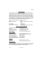
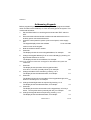
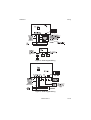
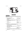
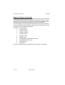
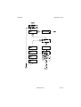
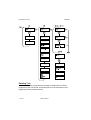
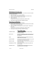
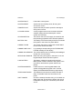
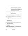
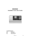
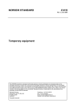
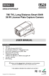
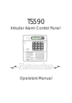
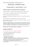
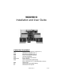
9600/9610
Installation and User Guide
COMPATIBLE EQUIPMENT
9624
9625
9626
9050
9040
9056
9076-01/02
9066
9685
947
951
Plug-on 4-Zone Expansion Card (max. 2)
9600 Remote Keypad (max. 4)
9610 Remote Keypad (max. 4)
Flush mounting kit for keypads
Internal loudspeaker
Plug-on Digital Communicator
Relay Interface
Self-Contained Bell (SCB Module)
Plug on Red Care S.T.U. (manufactured by others)
Serial Printer
Serial Printer with standby battery
Serial lead for 947 printer
496333 Issue 1
1 of 20
9600/9610
Introduction
The 9600 and 9610 control panels are designed for both domestic and
medium sized comercial installations. The control units provide connections
for eight zones on the main pcb, and can be expanded up to 16 zones by
adding two 9624 plug-on expander cards. The control unit pcbs are fitted in
blank steel cases, and connect to up to four remote keypads. Both systems
can accept plug-on communicators, and provide four open collector outputs
(bell and strobe plus two programmable). There is an additional programmable relay output on each 9624 expansion card (outputs 3 and 4).
The main differences between the 9600 and 9610 are:
9600
9610
Uses the 9625 keypad.
Uses the 9626 (backlit keys and status
LED).
128 event log.
250 event log.
Fire zone and double knock.
Not included.
Not included.
Coded remote reset, entry stray abort.
Technical Specification
Operating temperature
Humidity
Dimensions (main panel)
Weight (Control Panel)
Stand-by Battery
-10° C to + 40° C.
Up to 80% non-condensing.
h x w x d 330 x 350 x 76mm.
4.85 Kg (Excl. battery).
12 Volt, 6AH rechargeable battery.
Power Supply
System output current
System output current
Main Control Panel pcb
Each Remote Keypad
Standard 9066 SCB Module
Plug-on 9056 Communicator
1250mA (Ambient Temp. 20° C).
800mA (Ambient Temp. 40° C max.).
45mA quiescent.
45mA quiescent.
50mA quiescent.
30mA quiescent.
Outputs
OP 1 and 2
OP 3 and 4
500mA continuous, 1A surge.
Relay contacts rated at 2A, 24V DC.
Keypad Wiring
Recommended maximum distances for the remote keypads from the control
panel, using standard alarm cable is 100 metres for the star configuration,
300 m for the daisy chain configuration using four keypads.
2 of 20
496333 Issue 1
9600/9610
Addressing Keypads
Before programming the Control unit, the engineer must program an identification number into the NVM chip on each remote keypad in the system. This
is achieved as follows:
1. Set the PROG switch on each keypad to ON and the TEST switch to
OFF.
2. Ensure that the bells and strobe are disconnected and that there is no
auxiliary power connected to detectors.
3. Close the control panel lid, power up the control panel, mains supply
first.
The keypad display shows the software
V1:00 14/07/88
version numer of the keypad:
4.
5.
6.
Note the software version number.
Press NO.
The displays shows the current keypad address, for example:
1:01
Change the keypad address (if it is not correct already) by entering a 2digit number between 01 and 04.
The displays shows the new address, for example:
1:02
Note: If the system has more than one keypad on that address the system will
malfunction
7.
8.
9.
Press NO.
The display shows the status of the keypad sounder,
0 for ON or 1 for OFF (normally left at 0), for example:
2:0
Change the status of the sounder by pressing 1 or 0.
The display shows the selected status, for example:
2:1
Press NO.
The displays shows the current status of the keypad back light, 0 for
timed of 1 for always on, for example:
3:0
10. Change the backlight status as required by pressing 1 or 0.
The display shows the selected status, for example:
3:1
11. Press NO.
The display shows the current status of the keypad keys, 0 for keys
Active, 1 for keys Non-Active (normally left at 0), for example:
4:0
12. Change the keypad status as required by pressing 1 or 0.
The display shows the selected status, for example:
496333 Issue 1
4:1
3 of 20
Keypad Display Tests (Optional)
9600/9610
13. Repeat steps 4 to 12 for all the other keypads.
14. Set the PROG switch on each keypad to OFF and power down the
control panel to lock the keypad+s program into the their NVMs.
Keypad Display Tests (Optional)
15. Set the TEST switch on each keypad to ON and carry out the following
display tests for each keypad
a) Power up the control panel.
The display shows all 32 characters as solid black.
b)
Press NO.
The display clears and shows a cursor (line) at the top left hand character.
c)
Press all the number keys in turn, followed by No, Yes, A, B, C and D.
The display will show all number keys as the appropriate
number, the No key as ‘A’. Yes key as ‘B’, the ‘A’ key
as ‘C’, the ‘B’ key as ‘D’, the ‘C’ key as ‘E’ and the ‘D’
key as ‘F’, for example:
123456789ABCDEF
d) Repeat the keypad test for all system keypads.
16. Power down the control panel and set the TEST switches on all keypads
to OFF.
17. Refit all keypads onto their backplates, ensuring that their tamper
switches are closed.
18. Carry out the Initial Start Up procedure.
4 of 20
496333 Issue 1
9600/9610
Wiring
Figure 1. 9600 Control Panel Wiring
496333 Issue 1
5 of 20
Wiring
9600/9610
Figure 2. 9610 Control Panel Wiring
6 of 20
496333 Issue 1
9600/9610
Wiring
Figure 3. 9625 Keypad Wiring
Figure 4. 9626 Keypad Wiring
496333 Issue 1
7 of 20
Programming
9600/9610
Figure 5. Four-Zone expansion Board Wiring
Programming
Initial Start Up
Having programmed all the keypads in the system, power up the control
panel, battery first, then mains. Close the control panel lid and proceed as
follows:
The keypad display shows:
00:00 MON 01 JAN
1. Key in 1234 (the default User Code).
The display shows:
SYSTEM UNSET
followed by :
00:00 MON 01 JAN
(the displays may vary depending on system status)
2. Key in 07890 (the default engineer code).
The display shows:
RESET SYSTEM?
YES/NO
3. Press NO.
The display shows:
PROGRAM SYSTEM?
YES/NO
4. Press Yes.
Note: If after pressing ‘Yes’ to ‘PROGRAM SYSTEM’ you want to cancel this option,
press the ‘No’ key. This will also cancel the Keypad Sounder
5.
6.
7.
The keypad sounder gives a continuous tone,
and the display shows:
OPEN END STATION
Open the control panel lid.
If you are using an engineer keypad then plug it in at this point.
Press Yes twice.
The display shows:
PROGRAM ZONES?
YES/NO
Connect all auxiliary power connections for detectors and SAB.
Carry on to select one of the engineer functions (see “Engineer Program
Commands”).
8 of 20
496333 Issue 1
9600/9610
Defaults
Defaults
FUNCTION
User code authority
User code 1
User codes 2 to 7
Engineer code
Zone used
Zone description
Group, zone
Group, enable
Chime
24 hour monitoring
Double Knock
Omit Allowed
Zone on test
Exit mode
Exit time
Entry time
Alarm type
Instant bells
O/P 1 Output type
O/P 2 Output type
O/P 3 Output type
O/P 4 Output type
Bell type
Bell duration
Bell delay
Day tamper comms
System full reset
PA reset (9600 only)
Remote CSID (9610 only)
Abort facility
Line fault
Remote reset
Auto re-arm
Continuous sounder
Delayed Entry Alarm
Logging Printer
DESCRIPTION AND DEFAULTS
Master manager (user code 1)
1234
Not programmed
0 7890
Not used
Zone 1 to 16
None
Not used
Disabled
Disabled
Disabled (9600 only)
Disabled
Disabled
Timed
10 seconds
10 seconds
A=Full, B, C and D Local
Instant
Set Latch
Shock sensor reset
Entry/Exit follow (9610 = Bell Follow)
Bell follow
SAB
20 minutes
None
Disabled
Customer
Customer
Disabled
Disabled
Audible
Disabled
Once (9610 Always)
Disabled
Disabled
Disabled
496333 Issue 1
9 of 20
Programming Commands
9600/9610
Engineer Program Commands
While programming the system, the control unit shows a series of questions
on the keypad display. Answer the questions by pressing Yes or No on the
keypad. When you respond to a question the control unit will display further
questions in order to lead you through the programming sequence.
In the first stages of programming the system there are a set of numbered
entry points that let you go directly to a specific area of programming. These
numbers are shown in the following table:
Command Keypad display
1
Program zones?
2
Program Groups?
3
Program Outputs?
4
Program Bells?
5
Engineer Code?
6
Miscellaneous?
7
Load Defaults? (CSID Code? on 9610)
8
Load Defaults? (9610 only)
9
Reset System?
0
Walk Test?
The next four pages show the programming commands in more detail.
10 of 20
496333 Issue 1
9600/9610
Programming Chart
496333 Issue 1
11 of 20
Programming Chart
12 of 20
9600/9610
496333 Issue 1
9600/9610
Programming Chart
496333 Issue 1
13 of 20
Programming Chart
9600/9610
Entering Text
The 9629 Engineering Programming Template is designed for use when
programming the ‘free-format’ zone descriptions. Fit the template over the
keypad keys and proceed as follows:
14 of 20
496333 Issue 1
9600/9610
Entering Engineer Mode from Day Mode
Note: Press one of the four left hand keys before entering every letter, number or
space. If you make a mistake you can correct the entry by pressing the <- key
to delete characters . You can change existing descriptions to another
descripton by pressing the ‘No’ key to delete and then re-entering new description.
Entering Engineer Mode from Day Mode
1.
Key-in 0 then engineer code (for example: 7890)
The display shows:
RESET SYSTEM?
YES/NO
See -Initial Start Up+.
Enginer Reset
1.
2.
Key-in 0 then engineer code (for example: 7890)
The display shows:
RESET SYSTEM?
YES/NO
Press Yes.
496333 Issue 1
15 of 20
Refreshing the NVM
9600/9610
REFRESHING THE NVM (9600)
If the user and/or engineer codes are lost, or you wish to revert to the standard factory default codes:
1. Remove all power - both mains and battery.
2. Remove the NVM chip IC8 (above the large microcontroller chip).
3. Power up the panel - battery first then mains.
4. Refit the NVM chip.
The panel will now load the standard factory default codes.
5.
Re-program the panel with all the installation settings.
Refreshing the NVM (9610)
1.
2.
3.
4.
Remove all power - both mains and battery.
Place a small screwdriver between the two pins marked CON1 located
above the large microcontroller chip.
With the screwdriver shorting the pins, power the panel - battery first
then mains.
The panel will now load the standard factory default codes.
Re-program the panel with all the installation settings.
Error Messages
CANNOT RESET
System is unable to reset due to fault existing,
check as necessary.
EXIT FAULT
User has exceeded the programmed exit time or a
fault exists with the detection on exit route, check
as necessary.
FIRE
(9600 only) A smoke or heat detector fitted to the
system has been activated.
INVALID CODE
Incorrect user code has been entered, re-try up to 4
times before tamper alarm will occur.
MAINS FAILED
240V main supply to control panel lost, check fuse
board or spur outlet.
PERSONAL ATTACK
A personal attack button fitted to the system has
been activated.
PRINTER FAULT
The logging printer has been disconnected, deselected or has ran out of paper.
16 of 20
496333 Issue 1
9600/9610
Error Messages
SYSTEM FAULT
Fault within control panel.
SYSTEM RESET
System has successfully reset, all wiring and
circuits are correct.
TAMPER FAULT
System anti-tamper switch opened or damage to
wiring has occurred.
24 HOUR ALARM
A zone programmed as 24 hour alarm has been
violated, display will show description. Check
system as necessary.
AUX POWER FAIL
The load on the AUX 12V supply is excessive and
the protecting polyswitch fuse has been operated.
BATTERY FAIL
The battery has become faulty and will not maintain
the system in the event of a power failure.
COMMS FAILED
The system has tried to contact the central station
but for some reason has failed.
COMMS LINE FAULT
Log message corresponding to the TELEPHONE
FAILED message on the display.
COMMS SUCCESSFUL The central station has successfully acknowledged
receipt of a communication.
KEYPAD NN TAMPER
Either the wiring to keypad nn has been cut or the
keypad tamper switch has been opened.
LOW BATTERY
The battery voltage is at a seriously low level.
Mains power must be restored to the system in the
near future otherwise the system will fail completely.
SYSTEM INHIBITED
If there are two or more keypads fitted to the
system, all keypads except the one in use will
display SYSTEM INHIBITED during engineering.
TELEPHONE FAILED
The telephone line has become disconnected or
faulty. If possible check the connection to the
panel.
UNIT TAMPER
Check the external sounder wiring. If an SAB is not
fitted check that TR and 0V are linked. Also check
loudspeaker tamper (A/T connections) are closed
circuit .
496333 Issue 1
17 of 20
User Commands
9600/9610
WATCHDOG FAULT
A mains transient or severe electrostatic discharge
has upset the system software. The system has
restarted itself and should be functioning normally.
ZONE TEST FAILED
One or more zones are on 14 day test (soak test),.
Some of these zones have been violated during the
set period and would have caused an alarm. The
panel will continue to operate correctly.
KEYPAD 00 TAMPER
Mains power-up has occurred. Power down control
panel (mains and battery), then re-apply power
(battery first, then mains) to clear this fault.
User Commands
The end users operate the 9600 and 9610 systems by pressing Yes or No on
the keypads in response to a series of questions that the system presents in
the display.
Access to the systems’ functions is split into three authority levels : Manager,
Operator, and Block Omit. The default access code “1234” has Manager
authority. The system allows a total of seven codes, and any code can be
assigned to any authority level.
User authority allows access to:
a)
Arming, disarming and resetting the system (if not programmed for
Engineer reset).
b)
Omitting zones (if zones are Omit Allowed).
c)
Setting Chime on or off.
d)
Viewing the event log.
e)
Carrying out all test functions.
Manager authority also allows access to the following additional functions:
f)
Omitting and re-instating 24 hour zones (if zones are Omit Allowed).
g)
Setting system time and date.
h)
Changing user code authority.
i)
Changing and deleting user codes.
j)
Printing the log.
The Block Omit code has very limited authority. The code has no access to
any functions defined for User or Manager. The code does allow a user (for
example a cleaner) to arm or disarm any area defined as Group D, but only
while one of the other three groups is armed.
18 of 20
496333 Issue 1
9600/9610
Invalid Access Code Entered
Invalid access code entered
If you enter an invalid access code then the display shows:
INVALID ACCESS CODE? YES/NO
Press the ‘Yes’ or ‘No’ key and re-enter valid access code number.
Emphasise this point to customers when training them on the system.
496333 Issue 1
19 of 20
20 of 20
496333 Issue 1