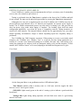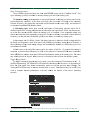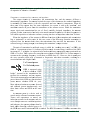
1
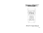
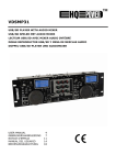
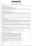
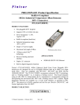
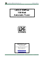
Z-100PLUS OP
PERATION
NS MANUAL
L
M
MANUAL
RE
EV A
LD
DG Z-100
Z 0Plus
s
100
0-Wa
att
Au
utoma
atic Tune
T er
LDG Electron
E
nics
1445 Parran Roadd
Stt. Leonard MD
M 20685-29903 USA
Phone: 410-586-2177
Fax: 410-586-847
4
75
[email protected]
www.ldggelectronics.ccom
PAGE 1
Table of Contents
Introduction
3
Jumpstart, or “Real hams don’t read manuals!”
3
Specifications
4
An Important Word About Power Levels
4
Important Safety Warning
4
Getting to know your Z-100Plus
5
Front Panel
Rear Panel
5
6
Installation
6
Operation
7
Basic Tuning Operation
Toggle Bypass Mode:
Initiate a Memory Tune Cycle:
Force a Full Tune Cycle:
Status Indicators
Application Information
Mobile Operation
MARS/CAP Coverage
Optional Internal Battery Installation
Icom Interfacing
Yaesu Interfacing
7
8
9
10
11
11
11
12
12
12
13
Theory of Operation
13
The LDG Z-100Plus
15
A Word About Tuning Etiquette
16
Care and Maintenance
16
Technical Support
16
Two-Year Transferrable Warranty
16
Out Of Warranty Service
16
Product Feedback
17
PAGE 2
INTRODUCTION
LDG pioneered the automatic, wide-range switched-L tuner in 1995. From its laboratories in
St. Leonard, Maryland, LDG continues to define the state of the art in this field with innovative
automatic tuners and related products for every amateur need.
Congratulations on selecting the Z-100Plus 100-watt automatic tuner. The Z-100Plus provides
semi-automatic antenna tuning across the entire HF spectrum plus 6 meters, at power levels up to
125 watts. It will tune dipoles, verticals, Yagis, or virtually any coax-fed antenna. It will match an
amazing range of antennas and impedances, far greater than some other tuners you may have
considered, including the built-in tuners on many radios.
The Z-100Plus may be optionally powered by internal batteries, eliminating the need for an
additional power cable to use the Z-100Plus. Latching relays are used, so the Z-100Plus consumes
no power when not tuning, so batteries only need to be replaced once per year or less.
JUMPSTART, OR “REAL HAMS DON’T READ MANUALS!”
Ok, but at least read this one section before operating the Z-100Plus:
Turn off power to your radio.
Connect the antenna jack on the transceiver to the “TX” jack on the Z-100Plus, using the supplied
50 ohm coax cable jumper.
Connect a 50 ohm coax antenna feedline to the “ANT” jack on the Z-100Plus.
Power up the transceiver and select the desired operating frequency.
Select AM, FM, CW, or PKT mode, and then key down to transmit a carrier1.
Push and hold the TUNE button on the front of the Z-100Plus for one second (until the Tuning
LED comes on), then release.
Wait for the tuning cycle to end (red LED goes out, 1 - 6 seconds) and then un-key.
Restore the transceiver to the desired operating mode.
You’re ready to transmit!
1
You can tune while transmitting up to 125 watts if your transceiver has a “roll-back” circuit to protect it from high SWR. If it does not
have a roll-back circuit, limit power when tuning to 10 watts.
PAGE 3
SPECIFICATIONS
0.1 to 125 watts SSB, CW, and digital modes.
Latching relays for ultra low power operation.
2,000 memories for instantaneous frequency and band changing.
7 to 18 Volts DC, 100 mA. Virtually zero current when not tuning.
Optionally internal battery powered, 7-18VDC
1.8 to 54.0 MHz continuous frequency coverage. Frequency for memory storage is
determined by internal frequency counter.
Tunes 6 to 800 ohm loads (16 to 150 on 6M), 16 to 3200 ohms with optional 4:1 Balun.
For Dipoles, Verticals, Vees, Beams or any Coax Fed Antenna.
Optional external Balun allows tuning of random length, long wire or ladder line fed
antennas.
Dimensions: 5”L x 5”W x 1.5”H.
Weight: 1.0 pounds
Includes 1 foot Icom and Yaesu 857/897 interface cable and 1 foot coaxial cable jumper.
AN IMPORTANT WORD ABOUT POWER LEVELS
The Z-100Plus is rated at 125 watts maximum power input at most. Many ham transmitters and
transceivers, and virtually all amplifiers, output well over 125 watts. Power levels that significantly
exceed specifications will definitely damage or destroy your Z-100Plus. If your tuner fails during
overload, it could also damage your transmitter or transceiver. Be sure to observe the specified
power limitations.
IMPORTANT SAFETY WARNING
Never install antennas or transmission lines over or near power lines. You can be seriously
injured or killed if any part of the antenna, support or transmission line touches a power
line. Always follow this antenna safety rule: the distance to the nearest power line should be
at least twice the length of the longest antenna, transmission line or support dimension.
PAGE 4
GETTING TO KNOW YOUR Z-100PLUS
Your Z-100Plus is a quality, precision instrument that will give you many years of outstanding
service; take a few minutes to get to know it.
Tuning is performed when the Tune button is pushed on the front of the Z-100Plus and held
for one second. The tuner can be placed in bypass mode by pressing the Tune button momentarily.
Although a DC coax jack is supplied on the rear of the Z-100Plus, the Z-100Plus may also be
powered directly from internal AA or 9V batteries (not supplied); no separate power supply is
needed. The Z-100Plus automatically powers up at the start of a tuning cycle, and goes into an
ultra low-power sleep mode when tuning is complete. The latching relays hold the tuned
configuration indefinitely, even when DC power is completely removed. Tuning memories are
stored in FLASH memory. The internal batteries should last for approximately one year under
normal operating circumstances; longer or shorter depending upon how frequently tuning is
performed.
The Z-100Plus has 2,000 frequency memories. When tuning on or near a previously tuned
frequency, the Z-100Plus uses “Memory Tune” to recall the previous tuning parameters in a
fraction of a second. If no memorized settings are available, the tuner runs a full tuning cycle,
storing the parameters for memory recall on subsequent tuning cycles on that frequency. In this
manner, the Z-100Plus “learns” as it is used, adapting to the bands and frequencies as it goes.
Front Panel
On the front panel there is one pushbutton and two LED indicator lights.
Tune Button: Initiates either a memory tune or a full tune, and also toggles the tuner
between “active” and “bypass” modes.
SWR LED: Lights steady green at the end of a tuning cycle to indicate a good match has
been found.
Tuning LED: Lights during tuning operation, will also blink error codes if a good tuning
match is not found.
PAGE 5
Rear Panel
The rear panel of the Z-100Plus features five connectors.
Antenna connector: Connect the 50-ohm coax antenna feedline to this standard SO-239
connector.
GND connector (wing nut): Connect to antenna system ground.
Transmitter connector: Connect the 50-ohm coax jumper cable from this standard SO-239
connector to the ANT jack on the back of the transceiver.
Power jack: 2.5x5.5mm DC coaxial jack. Connect to 7 to 18VDC, center positive.
Radio Interface jack: Connects via a control cable to a compatible transceiver.
PAGE 6
INSTALLATION
The Z-100Plus tuner is designed for indoor operation only; it is not water resistant. If you use it
outdoors (Field Day, for example), you must protect it from the rain. The Z-100Plus is designed
for use with coax-fed antennas. If use with longwires or ladder-line-fed antennas is desired, an
external balun is required. The LDG RBA-4:1 or RBA-1:1 is ideal, depending on the antenna and
transmission line used.
Always turn your radio off before plugging or unplugging anything. The radio may be
damaged if cables are connected or disconnected while the power is on.
Connect the HF antenna jack on the transceiver to the Transmitter jack on the back of the Z100Plus, using the supplied coax jumper cable, or a similar 50 ohm coax cable rated 125 watts or
greater.
The Z-100Plus can interface directly with several popular transceivers. For Icom radios, it will
enable their “Tune” button to start a tuning cycle and provide power to the tuner.
For Icom radios that are AH-3 or AH-4 compatible, connect the white Molex connector into
the radio’s tuner port. The power and radio plugs then connect to the tuner. The tuning process can
start by either pressing the tune button on the tuner or the radio.
For Yaesu FT-897 and 857, use the Y-ACC cable and plug the red end marked “Radio” into
the radio’s ACC port. Connect the black end marked “Tuner” into the tuner’s interface jack. The
radio does not supply power to the tuner. The tune button on the tuner is used for starting the
tuning process.
If you are not using an Icom interface cable for powering the tuner, connect the Z-100Plus to a
source of DC power capable of providing 7 – 18 volts DC at 300 mA, using the provided coaxial
connector (center positive). You can use two standard 9-volt alkaline transistor radio batteries
connected in series (this is very handy for portable operation). If your radio is powered by 12
VDC, you most likely can use the same power supply for the Z-100Plus.
Grounding the Z-100Plus tuner will enhance its performance and safety. LDG recommends
that you connect your tuner to a suitable ground; a common ground rod connected to buried radials
is preferred, but a single ground rod, a cold water pipe, or the screw that holds the cover on an AC
outlet can provide a serviceable ground. LDG strongly recommends the use of a properly installed,
high quality lightning arrestor on all antenna cables.
PAGE 7
OPERATION
Basic Tuning Operattion
Z
iss operated from
f
the fronnt panel TU
UNE button on the Z-1000Plus itselff2. Two
The Z-100Plus
types of tuning
t
cyclees are availabble; a memorry tuning cyycle and a fulll tuning cyccle.
The memory
m
tun
ning cycle attempts
a
to tune
t
quicklyy based on having
h
previously tuned on the
present frequency
f
seelection. If the tuner previously
p
w successfful in tuningg on the cuurrently
was
selected frequency, the
t settings for
f that matcch will be looaded into thhe tuner relaays, and checcked to
see that an
a acceptablee SWR matcch is found.
A full tuning cy
ycle “starts from scratchh” and begiins a fixed tuning
t
sequence where the Z100Plus rapidly
r
triess varying com
mbinations of
o inductancce and capacitance valuees, and then zeroesz
in on thee best match
h possible. When
W
the tuuning cycle is completee, if an acceeptable matcch was
found, thhe inductance and capaciitance settinngs are savedd in a memoory associateed with the selected
s
frequencyy, so that theey may be reecalled quickkly in the futture via a meemory tuninng cycle.
In thiis manner, th
he Z-100Plus “learns”; thhe longer yoou use it, thee more closelly it adapts itself
i
to
the bands and frequeencies used. Most users will probabbly use mem
mory tuning most
m of the time;
t
it
takes advvantage of an
ny saved tunning settingss, but automaatically defaaults to a fulll tuning cycle if no
stored daata is availab
ble.
In booth cases, at the end of the
t tuning cyycle, the carrrier is held for 1.5 secoonds after tuuning is
completee, so that thee final SWR
R may be reaad on the traansceiver’s internal
i
SWR
R meter or another
a
inline SW
WR meter, an
nd the front panel LEDss will indicaate the statuss of the tuninng cycle. Thhe tuner
may alsoo be placed in
n “bypass” mode
m
where it is electrically removed from the antenna
a
systeem.
Toggle Bypass
B
Modee:
To tooggle betweeen bypassedd and active mode, press the front panel
p
Tune button on thhe Z100Plus momentarily
m
y. The SWR
R LED will flash
f
three too indicate thhat the tuner is in bypasss mode.
Press thee front paneel Tune buttton momenttarily again to recall thee previous tuner
t
settinggs. The
Tuning LED
L
will flaash once to inndicate that the tuner is active. Thiss function may
m be usefull if you
wish to compare an
ntenna perfoormance with and withhout the bennefit of thee tuner’s maatching
network.
2
If a compattible Icom transceiiver is connected viia the interface cabble, the tuner mayy be operated from the “tuner” buttoon on the Icom raddio,
also.
PAGE 8
Initiaate a Memoryy Tune Cyclle:
To innitiate a mem
mory tuning cycle, key the
t transmittter, then preess and holdd the Tuning button
on the froont of the Z--100Plus unttil the Tuninng LED lightts up, then reelease. A meemory tuning cycle
will begin.
Forcee a Full Tun
ne Cycle:
Someetimes, if yo
ou are transsmitting on a previouslyy tuned freqquency, perfforming a memory
m
recall tunne will find a stored mattch that is accceptable, buut is not as optimal
o
as coould be. This could
be the caase if you reccently made modifications to your antenna,
a
for example.
e
In this case, foorcing a
full tune will cause the
t Z-100Pluus to seek a better matchh than the match
m
alreadyy stored in memory
m
fr
for this frequency.
To force a full tuning cyclee, key the trransmitter, thhen press annd hold the Tune
T
buttonn on the
front paanel of the Z-100Plus
Z
unntil the Tuning LED ligghts up, and keep holdinng until the Tuning
T
LED goes
g
out agaain. Release the Tune button
b
once the Tuningg LED goes out. A full tuning
cycle will
w begin.
PAGE 9
Status Indicators
The SWR LED and Tunin
ng LED are both used to indicate both operatting modes, tuning
status, annd error codees. The folloowing table lists
l
the LED
D status codees and their meaning.
m
LED In
ndication
Mean
ning
Tuning LED on.
Tuner is tuning.
Tuning LED goes out,
SWR LED
L
comes on solid.
Tuner has comp
pleted a tuning cycle;
a goo
od SWR ma
atch was found.
Tuning LED goes out,
SWR LED
L
blinks 5 times.
Tunin
ng cycle is complete;
c
tuning
g match is between 1.5 and 3.0 SWR.
S
Tuning LED goes out, no SW
WR LED.
Tunin
ng cycle is complete;
c
tuning
g match is greater
g
than 3.0:1 SW
WR.
Tuning LED blinks
s 4 times.
Tunin
ng cycle failled, RF wass lost in the
e
middlle of the tun
ne.
Tuning LED blinks
s 5 times.
Tunin
ng cycle failled, no RF was detectted.
APPLIC
CATION IN
NFORMATIION
Mobile Operation
O
The Z-100Plus
Z
iss perfectly suited to mobbile operatioon. It can bee installed unnder the dasshboard
along wiith the transcceiver, or mounted
m
rem
motely. The only
o
requirement is thatt the tuner remains
r
dry.
dio interfacee cable is 14 inches loong. If it is desired thatt the Z-100Plus is
The supplied rad
positioneed farther fro
om the transcceiver than this
t cable lenngth allows, a custom caable will neeed to be
constructted. This caan be accom
mplished in two
t
ways: Cut
C the suppllied cable annd solder a jumper
j
wire betw
ween all thee connectionns, or purchaase new connnectors andd cable to construct a customc
length innterface cable from scrattch. The connnectors are standard 1/88” stereo pluugs, availablle from
most eleectronic supp
ply catalogss, such as Mouser
M
Elecctronics. The female jaack is Mousser part
number 16PJ106-EX
1
X, and the maale plug is Mouser
M
part number
n
17PP
P004-EX.
PAG
GE 10
MARS/CAP Coverage
The Z-100Plus provides continuous tuning coverage over its specified range; not just in the
ham bands. This makes it useful for MARS or CAP operation, or any other legal HF operation.
Optional Internal Battery Installation
The Z-100Plus is designed to allow the user to install his own internal battery pack. The
internal battery must be between 7 and 18V DC. A single 9V battery or a 6 or 8-cell AA or AAA
battery holder with batteries installed.
In order to install an internal battery supply, the lid of the Z-100Plus must be removed by first
removing the four screws on the side of the case. Connection of the battery pack to the Z-100Plus
is made via the two battery solder pads at J8 and J9. J8 is the negative terminal, and J9 is the
positive terminal.
Solder a pair of 20AWG or smaller wires to the solder pads at J8 and J9, being careful to
observe the polarity of the connections. The battery pack should be secured to prevent it from
moving around inside the case. For many installations, simply fastening the battery pack to the top
of the relays with double sided tape is sufficient. Care should be taken not to splash solder onto the
circuit board, nor to leave any loose objects inside the case when re-assembling the tuner.
PAGE 11
Icom Interfacing
When interfacing the Z-100Plus with AH-3 and AH-4 compatible Icom radios (IC-706, IC7000, for example), the Z-100Plus may be operated from the radio’s TUNER/CALL button. Push
the TUNER/CALL button momentarily to toggle the bypass of the Z-100Plus. Push and hold the
TUNER/CALL button for 2 seconds to initiate a memory tuning cycle. Note that the TUNER
button on the Icom IC-756 Pro series transceivers will not activate the Z-100Plus, but pushing
TUNE on the Z-100Plus will still automatically activate the carrier on the IC-756 Pro when using
the Icom interface cable. When using the IC-718, choose AH-4 from the tuner menu.
Yaesu Interfacing
When interfacing the Z-100Plus with an FT-857 or FT-897 using the Y-ACC cable, the Tune
button on the Z-100Plus is used to initiate a tune. The Z-100Plus will automatically key the radio
at the current power level during a tuning cycle and un-key when the tuning cycle is complete.
THEORY OF OPERATION
Some basic ideas about impedance
The theory underlying antennas and transmission lines is fairly complex, and in fact employs a
mathematical notation called “complex numbers” that have “real” and “imaginary” parts. It is
beyond the scope of this manual to present a tutorial on this subject3, but a little background will
help in understanding what the Z-100Plus is doing, and how it does it.
In simple DC circuits, the wire resists current flow, converting some of it into heat. The
relationship between voltage, current, and resistance is described by the elegant and well-known
“Ohm’s Law”, named for Georg Simon Ohm of Germany, who first discovered the principle in
1826. In RF circuits, an analogous but more complicated relationship exists.
RF circuits also resist the flow of electricity. However, the presence of capacitive and inductive
elements causes the voltage to lead or lag the current, respectively. In RF circuits, this resistance to
the flow of electricity is called “impedance”, and can include all three elements: resistive,
capacitive, and inductive.
The output circuit of a transmitter consists of inductors and capacitors, usually in a
series/parallel configuration called a “pi network”. The transmission line can be thought of as a
long string of capacitors and inductors in series/parallel, and the antenna is a kind of resonant
3
For a very complete treatment of this subject, see any edition of the ARRL Handbook for Radio Communications (previously the
Handbook for Radio Amateurs).
PAGE 12
circuit. At
A any given RF frequenccy, each of these
t
can exhhibit resistannce, and imppedance in thhe form
of capaciitive or inducctive “reactaance”.
Transmittters, transmission lines, anntennas, and impedance
i
The output circu
uits of a trransmitter, the transmission line, and the anntenna, all have
h
a
characterristic impedaance. For reaasons beyonnd the scope of this docuument, the standard imppedance
is nominnally 50 ohm
ms resistive,, with zero capacitive and
a zero indductive com
mponents. When all
three parrts of the sy
ystem have the same impedance, the system is said to be
b “matchedd”, and
maximum
m transfer of
o power froom the trannsmitter to the
t antenna occurs. Whhile the trannsmitter
output circuit and transmission
t
n line are of
o fixed, carrefully designed impeddance, the antenna
a
n-reactive looad only at itts natural ressonant frequuencies. At other
o
frequenncies, it
presents 50-ohm, non
ve or inductivve reactancee, causing it to
t have an im
mpedance otther than 50 ohms.
will exhibit capacitiv
d
from
m that of thhe transmitteer and transm
mission
Whenn the impedance of the antenna is different
line, a “m
mismatch” is
i said to exxist. In this case, some of the RF energy
e
from
m the transm
mitter is
If this
reflected from the antenna
a
bacck down thee transmissiion line andd into the transmitter.
t
reflected energy is sttrong enoughh, it can dam
mage the trannsmitter’s ouutput circuitss.
r
of tran
nsmitted to reflected
r
eneergy is called the “standding wave raatio”, or SW
WR. An
The ratio
SWR of 1 (sometimees written 1:1) indicates a perfect maatch. As morre energy is reflected,
r
the SWR
increasess to 2, 3, or higher.
h
As a general rulee, modern soolid state traansmitters muust operate with
w an
SWR of 2 or less. Tu
ube exciters are somewhhat more toleerant of highh SWR. If a 50 ohm anttenna is
s
an SW
WR close to 1. However,, this is usuaally not
resonant at the operaating frequenncy, it will show
t
resonannce, resultinng in a
the case;; operators often need to transmitt at frequencies other than
reactive antenna
a
and a higher SW
WR.
F = Forward power
p
R = Reflected
d power
SW
WR is measured using
a device
d
calledd an “SWR
bridge”, inserted in the transm
mission line
between the transm
mitter and thhe antenna.
This circuit measuress forward annd reflected
power froom which SWR may bee calculated
(some meters
m
calcu
ulate SWR for you).
More advvanced unitss can measuure forward
and refleected powerr simultaneously, and
show theese values and
a SWR att the same
time.
An antenna
a
tuneer is a device used to
cancel ouut the effectss of antennaa reactance.
Tuners add capaciitance to cancel
c
out
inductivee reactance in the antennna, and vice
versa. Sim
mple tuners use variablee capacitors
and inductors; the op
perator adjussts them by
hand whhile observin
ng reflected power on
the SWR
R meter untill a minimum
m SWR is reaached. The LDG
L
Electroonics Z-100P
Plus automaates this
PAG
GE 13
process.
No tuner will fix a bad antenna. If the antenna is far from resonance, the inefficiencies inherent
in such operation are inescapable; it’s simple physics. Much of the transmitted power may be
dissipated in the tuner as heat, never reaching the antenna at all. A tuner simply “fools” the
transmitter into behaving as though the antenna is resonant, avoiding any damage that might
otherwise be caused by high reflected power. For best performance, the antenna used should
always be as close to resonance as is practical.
THE LDG Z-100PLUS
In 1995, LDG Electronics pioneered a new type of automatic antenna tuner. The LDG design
uses banks of fixed capacitors and inductors, switched in and out of the circuit by relays under
microprocessor control. An additional relay switches between high and low impedance ranges. A
built-in SWR sensor provides feedback; the microprocessor searches the capacitor and inductor
banks, seeking the lowest possible SWR. The tuner is a “Switched L” network, consisting of series
inductors and parallel capacitors. LDG chose the L network for its minimum number of parts and
its ability to tune unbalanced loads, such as coax-fed dipoles, verticals, Yagis, and, in fact,
virtually any coax-fed antenna.
The series inductors are switched in and out of the circuit, and the parallel capacitors are
switched to ground under microprocessor control. The high/low impedance relay switches the
capacitor bank either to the transmitter side of the inductor bank, or to the antenna side. This
allows the Z-100Plus to handle loads that are either greater than or less than 50 ohms. All relays
are sized to carry 125 watts continuously.
The SWR sensor is a variation of the Bruene circuit. This SWR measuring technique is used in
most dual-meter and direct-reading SWR meters. Slight modifications were made to the circuit to
provide voltages instead of currents for the analog-to-digital converters that provide signals
proportional to the forward and reflected power levels. The single-lead primary through the center
of the sensor transformer provides RF current sampling. Diodes rectify the sample and provide a
DC voltage proportional to RF power. These two voltages are read by the ADCs in the
microprocessor, and are used to compute SWR in real time.
The relays are powered by the 12VDC input provided by the DC coax jack or the optional
internal batteries. The relays are a latching type, and so they consume no current when not
actively switching. Although the microprocessor’s oscillator runs at 8 MHz, which allows the main
tuning routine to execute in only a few milliseconds, the relays require several milliseconds of
settling time for every combination of inductors and capacitors. Thus, it may take several seconds
before all relay combinations are exhausted, in the case of a difficult tune.
The tuning routine uses an algorithm to minimize the number of tuner adjustments. The routine
first de-energizes the high/low impedance relay if necessary, and then individually steps through
the inductors to find a coarse match. With the best inductor selected, the tuner then steps through
the individual capacitors to find the best coarse match. If no match is found, the routine repeats the
coarse tuning with the high/low impedance relay energized. The routine then fine tunes the
inductors and capacitors.
The microprocessor runs a fine tune routine just after the tuner finds a match of 1.5:1 or less.
This fine tune routine now tries to adjust the SWR as low as possible (not just to 1.5); it takes
PAGE 14
about half a second to run.
A WORD ABOUT TUNING ETIQUETTE
Be sure to use a vacant frequency when tuning. With today’s crowded ham bands, this is often
difficult. However, causing interference to other hams should be avoided as much as possible. The
Z-100Plus’s very short tuning cycle, as little as a fraction of a second, minimizes the impact of
tuning transmissions.
CARE AND MAINTENANCE
The Z-100Plus tuner is essentially maintenance-free. Power limits in this manual should be
strictly adhered to. The outer case may be cleaned as needed with a soft cloth slightly dampened
with household cleaning solution. As with any modern electronic device, the
Z-100Plus can be
damaged by temperature extremes, water, impact, or static discharge. LDG strongly recommends
the use of a good quality, properly installed lightning arrestor in the antenna lead.
TECHNICAL SUPPORT
The LDG Customer Support Center staff is ready to answer your product question by
telephone and over the Internet. We know that you will enjoy your product even more knowing
LDG is ready to answer your questions as the need arises.
Visit the Support Center at: http://support.ldgelectronics.com
Our website links you to the on-line Customer Support Center where you can send us a
question, do your own research in the LDG Product Knowledge Books, and read through lists of
frequently asked product questions. LDG regularly updates on-line information so the best on-line
support information is available all day and every day.
The LDG website provides links to product manuals, just in case you lose this one! When you
are thinking about the purchase of other LDG products our website also has complete product
specifications and photographs you can use to help make your purchase decision. Don’t forget the
links to all of the quality LDG Dealers also ready to help you make that purchase decision.
TWO-YEAR TRANSFERRABLE WARRANTY
Your product is warranted against manufacturer defects in parts and labor for two full years
from the date of purchase. This two-year warranty is also transferable. When you sell or give away
your LDG product, give the new owner a copy of the original sales receipt and the two-year
warranty transfers to the new owner.
There is no need to complete a warranty card or to register an LDG product. Your product
purchase receipt establishes eligibility for warranty service, so save the receipt. Send a photocopy
of the receipt with the product whenever you send your product to LDG for repair. Products sent to
LDG without a receipt are considered requests for out-of-warranty repair.
LDG does not warranty against product damage or abuse. This means that a product failure, as
determined by LDG, to be caused by the customer or by other natural calamity (e.g. lightning) is
not covered under the two-year warranty. Damage can be caused by failure to heed the product’s
published limitations and specifications or by not following good Amateur practice.
PAGE 15
OUT OF WARRANTY SERVICE
Any time a product fails after the warranty, LDG wants to help you get it fixed. Send the
product to us for repair and we will determine what needs to be done. Based on your prior
instruction, we will either contact you with an estimate or fix it and contact you with a request to
pay any repair charges. Please contact LDG if you have any questions before you send us an outof-warranty product for repair.
RETURNING YOUR PRODUCT FOR SERVICE
Returning a product to LDG is easy. We do not require a return merchandise authorization.
Visit the Customer Support Center and download the LDG Product Repair Form. On the Repair
Form tell the LDG technicians exactly what happened or didn’t happen and why you believe the
product needs servicing. The technician attempts to duplicate the problem(s) you had based on
how well you describe it so take the time to be accurate and complete.
Ask your shipper for a tracking number or a delivery verification receipt. This way you know
the product arrived safely at LDG. Be sure to give us your email address so our shipper can alert
you online when your product is en-route back to you. We regret that we are not able to provide
periodic updates on the status of repairs. Please be assured that our staff makes every effort to
complete repairs ahead of our published wait time. Your patience is appreciated.
Repairs can take six to eight weeks, but are usually faster than this. The most recent
information on returning products for service is found at the LDG Customer Support Center.
Ship your carefully packaged repair with the Repair Form to:
LDG Electronics, Inc.
Attn: Repair Department
1445 Parran Rd
St. Leonard, MD 20685
PRODUCT FEEDBACK
We encourage product feedback! Tell us what you really think of your LDG product. In a card,
letter, or email (preferred) tell us how you used the product and how well it worked in your
application. Send along a photo, schematic or drawing to illustrate your narrative. We like to share
your comments with our staff, our dealers, and other customers at the LDG website.
http://www.ldgelectronics.com/
PAGE 16
PAG
GE 17