1
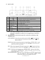
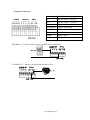
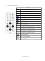
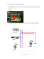
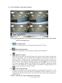
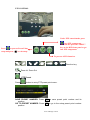
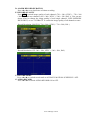
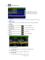
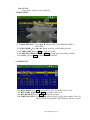
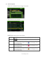
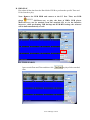
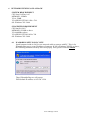
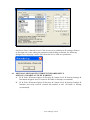
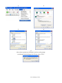
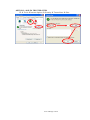
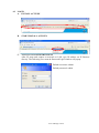
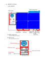
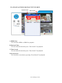
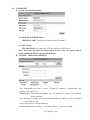
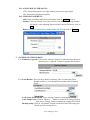
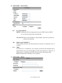
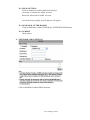
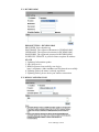
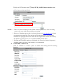
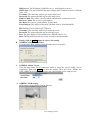
Pages from DVMR-N4e User Manual (H264 MPEG 4 version) 2.1 FRONT PANEL DVR OPERATION NO. LABEL 1 2 LED REC CONTROL 3 PANEL OPERATION IR Sensor For Remote Control. Led Indicator PTZ Record, Playback And Control Button. 4 1-4 & Quad Press The Button To Display No.1~No.4 Full Screen and Quad Screen 5 ▲▼◄► & MENU Button Of Controller. Button Of Menu Screen 6 ENTER © ENTER and BACKUP Button USB Connector. 7 www.allthings.com.au UP, DOWN, LEFT & RIGHT 2.2 BACK PANEL NO. LABEL OPERATION USB Mouse Connector (Only by supplied mouse). 1 2 VIDEO INPUT Video input with BNC connector. 3 MONITOR OUT Video output with BNC connector. 4 AUDIO OUT/ IN Audio output/ input. 5 7 ETHERNET RS-485/ ALARM/ RELAY VGA D-SUB OUT RJ-45 connector for network. 4 pin connector for external control unit, 5 pin connector for Alarm input and 3 pin connector for relay Connect to CRT or LCD monitor. 8 POWER Power switcher: DC 12V 5A / 50-60 Hz input. 6 NOTE: Please plug in the supplied mouse to DVR mouse connector before turn on the DVR. DO NOT REMOVE and PLUG IN the supplied mouse while DVR is operating. 2.3 ADVANCED AUTO SWITCH, ZOOM, PTZ, COPY KEY CONTROL & USB INFORMATION AUTO SWITCH : In the split screen mode, use the “QUAD+ ” keys in the front panel to enable auto switch function. Moreover, press “ ” key again to disable it. ZOOM :In the full screen mode, user can use compound key “ ENTER/ COPY ” on the front panel to perform ZOOM function. Press ▲▼◄►, located on the front panel, to move the zoom window. PTZ : When camera supported PTZ function, user can use “ ” button on the front panel to perform PTZ function. Press ▲▼◄► to select and change setup value. COPY : Within the playback mode, press “ ENTER/ COPY ” button to start backup record and press “ ENTER/ COPY ” again to end backup. The user can see the backup image approx. 3 ~5 sec. USB INFORMATION: Within the LIVE VIEWING, press “ENTER” key in the front panel will present the USB information. (NOTE: Please confirm that USB Device has plugged into DVR.) www.allthings.com.au 2.4 EXTERAL ALARM There are three types of alarms that the system can be configured to handle. They are Motion detection Alarm, External Alarm and Video Loss Alarm. A. Motion detection Alarm and External Alarm: When motion detection or External Alarm was triggered, there are 5 possible actions will be taken. a. Changes recording speed as alarm recording speed. b. Monitor will display corresponding full screen alarm channel, it will switch automatic mode to manual mode if buttons pressing activity occurred in 5 seconds. c. Relays can be activated by motion detection or external alarm when turning on. d. The camera title will be transformed into color of yellow when motion is happening, “ALARM” text will show up when external alarm is triggered. B. Video Loss Alarm: The default setting of Video Loss alarm is enabled. www.allthings.com.au Terminal Connectors: D+ RS-485 sends +/ receives + D- RS-485 sends -/ receives - D+ RS-485 sends +/ receives + D- RS-485 sends -/ receives - ALARM1-4 Camera alarm input. GND GND. N.C Relay N.C. COM Relay COM N.O Relay N.O. EXAMPLE 1:Connect Alarm In One with PIR (Passive Infrared). EXAMPLE 2:Connect with Alarm Siren at Relay N.O. www.allthings.com.au 2.5 IR REMOTE CONTROL ITEM REC Press REC to start recording and press twice to stop. 1-4 Select channel 1-4 with full screen. QUAD Fast backward. Picture by picture backward. Picture by picture forward. Fast Forward. Play video forward. COPY Switch channel format. ▲ Move upward or increase the number. ► Move rightward or increase the number. ▼ Move downward or decrease the number. ◄ Move leftward or decrease the number. Enter selected items. MENU Enter or Exit Main Menu. STOP Stop the playback. www.allthings.com.au 2.6 PTZ (PAN, TILT AND ZOOM) CAMERA Following diagram for DVR connect between PTZ camera & joystick controller, for DVR to control PTZ camera please make sure the CAMERA ID, BANDRATE (default at 9600 bps) and RS-485 cable. 2 CORE Under “Two Core” connection, controller can control speed dome without integrated protocol into DVR. Moreover, one keyboard can connect MAX 256 units of speed dome. www.allthings.com.au 3 SYSTEM SETUP 3.1 MENU SETUP INTERFACE(GUI) A. CAMERA SET B. MOTION SETUP C. RECORD SETUP D. ALARM SETUP E. HARD DISK SETUP F. www.allthings.com.au NETWORK SETUP G. BACKUP SETUP H. www.allthings.com.au SYSTEM SETUP 3.2 LIVE VIEWING AND POP-UP MENU NOTE:The pop-up menu can be activated by moving the mouse cruise to the bottom of the live viewing screen. A. GUI MENU BAR With live viewing mode, press this button to get into the GUI menu. B. DISK INFORMATION With live viewing mode, press this button to display disk information. C. DIGITAL ZOOM In the full screen mode, left-click the button of the mouse to pull a range to zoom in or zoom out the image. User can right-click the button of the mouse to disable this function. (NOTE: Using the mouse to operate digital zoom can zoom in to max. 16 times.) Moreover, user can also use compound key on the front panel to perform this function. (First, click ENTER/COPY Key and then click ▲▼◄► key to select zoom in or zoom out position. Finally, click ENTER/COPY key again to complete the setting. Moreover, click MENU Key to disable digital zoom function. Using the panel key to perform zoom in function is fixed at 2 times.) D. PTZ CONTROLLER Within live-viewing mode, Clicks this button to get into the PTZ setup menu. User can also use PTZ key on the front panel to perform this function. Moreover, user can right-click the button of the mouse or press the PTZ key on the front panel again to exit PTZ Setup. NOTE: Only for the camera supported PTZ function. www.allthings.com.au PTZ CONTROL Under PTZ control mode, press Press into PTZ setup menu. User can also press the “MENU” key on the DVR front panel to get into PTZ setup menu. to process Preset Point setup and press “■” to exit setup To process AUTO function. / / / / / / / Direction key Zoom In/ Zoom Out PTZ Preset Press button to entry PTZ preset point menu. SAVE PRESET NUMBER: Press SET to save preset point number and its position. GO TO PRESET NUMBER: Press SET to go to the setup preset point number position. www.allthings.com.au PTZ SETUP MENU LEFT-RIGHT SPEED: Use the mouse wheel to change the left-right speed. UP-DOWN SPEED: Use the mouse wheel to change the up-down speed. AUTO SPEED: Use the mouse wheel to change the auto patrol speed. BAUD RATE: Use the mouse wheel to change the BAUD rate. PROTOCOL: Use the mouse wheel to change the connection protocol. 3.3 E. AUDIO CONTROL Press this button to turn the audio on or off. F. DISPLAY CONTROL Within live-viewing or playback mode, use display control to switch the camera channel. G. RECORD AND PLAYBACK CONTROL Same as front panel controller and remote controller. CAMERA SETUP Press ▲ or ▼ to select items. Press ◄ or ► to change values. Press SET to see more options. A. CAMERA Press ◄ or ►/ mouse wheel to switch channels. B. VIDEO ADJUST www.allthings.com.au B-1. CONTRAST Press ◄ or ►/ mouse wheel to change contrast level. B-2. BRIGHTNESS Press ◄ or ►/ mouse wheel to change brightness level. B-3. HUE Press ◄ or ►/ mouse wheel to change HUE level. www.allthings.com.au B-4. COLOR Press ◄ or ►/ mouse wheel to change color level. B-5. SHAPRNESS Press ◄ or ►/ mouse wheel to change sharpness level. C. CAMERA TITLE Use mouse to select and change character. D. DISPLAY Press ◄ or ► to/ mouse wheel change value for the corresponding camera would be displayed on the screen or not. E. DWELL TIME Press ◄ or ►/ mouse wheel to ON/OFF auto switch and the switch sec.. F. PTZ SETUP LEFT-RIGHT SPEED: Use the mouse wheel to change the left-right speed. UP-DOWN SPEED: Use the mouse wheel to change the up-down speed. AUTO SPEED: Use the mouse wheel to change the auto patrol speed. BAUD RATE: Use the mouse wheel to change the BAUD rate. PROTOCOL: Use the mouse wheel to change the connection protocol. www.allthings.com.au 3.4 MOTION SETUP Press ▲ or ▼ to select items. Press ◄ or ► to change values. Press SET to see more options. A. CAMERA Press ◄ or ►/ mouse wheel to switch channels. B. MOTION DETECT Press ◄ or ►/ mouse wheel to change value for motion detect function. C. BUZZER Press ◄ or ►/ mouse wheel to change value for buzzer while motion detected. D. SENSITIVITY Press ◄ or ►/ mouse wheel to change sensitivity value from 001 (minimum) to 100 (maximum). E. AREA SETUP 1. Press SET to enter Motion Area Setting. (Note: The default setting of all area is “MOTION ON”.) 2. Use the mouse to select which block is needed. The green area shows the area without motion detection. www.allthings.com.au 3. Left-Click the mouse to see more options or exit the setup. SELECT: Cancel the selected area. CLEAR: Select the area without motion detection. EXIT: Exit the motion detection setup. 3.5 RECORD SETUP Press ▲ or ▼ to select items. Press ◄ or ► to change values. Press SET to see more options. A. RESOULTION Press ◄ or ►/ mouse wheel to switch record resolution. HALF D1: 720 x 240 (NTSC)/ 720 x 288 (PAL). CIF: 360 x 240 (NTSC)/ 360 x 288 (PAL). NOTE: If record resolution is altered in here, DVR will reboot automatically. www.allthings.com.au B. NORMAL RECORD PPS Press SET to change the PPS in normal recording. User can click “AVERAGE” to set PPS automatically by system or change the PPS for each channel manually. Record Resolution: HALF D1: 720 × 240 ( NTSC ) / 720 × 288 ( PAL ) Record Resolution: CIF: 360 × 240 ( NTSC ) / 360 × 288 ( PAL ) C. ALARM RECORD PPS Press SET to change the PPS in alarm recording. User can click “AVERAGE” to set PPS automatically by system or change the PPS for each channel manually. Record Resolution: HALF D1: 720 × 240 ( NTSC ) / 720 × 288 ( PAL ) Record Resolution: CIF: 360 × 240 ( NTSC ) / 360 × 288 ( PAL ) www.allthings.com.au D. ALARM RECORD DURATION Press ◄ or ► to set dwell time of alarm recording. E. RECORD QUALITY Press SET to switch image quality of each channel (720 × 240 ( NTSC ) / 720 × 288 ( PAL )) or each two channels (360 × 240 ( NTSC ) / 360 × 288 ( PAL )). User can use mouse wheel to change the image quality of each single channel: LOW/ MEDIUM/ HIGH/ BEST, or use “AVERAGE” to switch the image quality of all channels at once. Record Resolution: HALF D1: 720 × 240 ( NTSC ) / 720 × 288 ( PAL ) Record Resolution: CIF: 360 × 240 ( NTSC ) / 360 × 288 ( PAL ) F. RECORD MODE Press ◄ or ► to switch record mode to ALWAYS/ MOTION/ SCHEDULE / OFF. G. AUDIO RECORD Press ◄ or ► to switch AUDIO RECORD ON or OFF. www.allthings.com.au H. SCHEDULE SETUP Press SET to get into schedule setup menu。 1. Use mouse to select schedule day/ time/ mode. 2. Click 3.6 to save change and exit. ALARM SETUP Press ▲ or ▼ to select items. Press ◄ or ► to change values. Press SET to see more options. A. EXT. ALARM MODE Select N.C for “normal close” alarm input, or select N.O for “normal open” alarm input. B. ALARM DISPLAY MODE Press ◄ or ►/ mouse wheel to change value for ALARM DISPLAY MODE with full screen. C. VIDEO LOSS DETECT Press ◄ or ►/ mouse wheel to switch VIDEO LOSS ALARM ON or OFF. D. EVENT LOG SETUP Press SET to change value for MOTION EVENT / VIDEO LOSS EVENT to ON / OFF. E. BUZZER TIME SETUP Press SET to set dwell time of BUZZER/ ALARM. F. RELAY TIME SETUP Press SET to set dwell time of RELAY. www.allthings.com.au 3.7 HARD DISK MANAGEMENT SETUP Press ▲ or ▼ to select items. Press ◄ or ► to change values. Press SET to see more options. A. OVERWRITE MODE Press ◄ or ► to change value OVERWRITE MODE ON or OFF. B. CAPACITY WARNING (When Overwrite Mode is OFF, Capacity Warning will enable) Press ◄ or ► to change value to 20/ 15/ 10 or 5% with non-overwrite mode. When LEFT RATIO is below the setting, it will enable AUDIBLE ALARM (If AUDIBLE ALARM of BUZZER of ALARM SETUP is ON). C. HDD INFORMATION Press SET to display HDD information. D. HDD FORMAT SETUP D-1. HDD PASSWORD PROTECT Press ◄ or ►/ mouse wheel to change value for hard disk format password protection. D-2. HDD PASSWORD Press SET then use mouse to change password. Default password: 1111 D-3. HDD FORMAT Press SET to get into FORMAT setup. Press YES or NO to execute. www.allthings.com.au 3.8 NETWORK SETUP Press ▲ or ▼ to select items. Press ◄ or ► to change values. Press SET to see more options. A. IP MODE Press ▲ or ▼ to select items and ◄ or ►/ mouse wheel to change to STATIC IP or DHCP. B. HTTP PORT Press ▲ or ▼ to select items and ◄ or ►/ mouse wheel to change WEB PAGE PORT. C. IP ADDR Press ▲ or ▼ to select items and SET to change IP ADDRESS. D. NETMASK Press ▲ or ▼ to select items and SET to change SUBNET MASK. E. GATEWAY Press ▲ or ▼ to select items and SET to change Default GATEWAY. F. DNS1 Press ▲ or ▼ to select items and SET to change DNS. G. DNS2 Press ▲ or ▼ to select items and SET to change OTHER DNS. H. PPPoE H-1. PPPoE SETTING Press◄ or ►/ mouse wheel to ENABLE / DISABLE PPPoE. H-2. USER NAME Use mouse to setup user name for ADSL account. H-3. PASSWORD Use mouse to setup password for ADSL account. www.allthings.com.au H-4. STATE Press SET to display status of PPPoE。 I. DDNS SETUP I-1. DDNS SETTING:Press◄ or ►/ mouse wheel to set DDNS ENABLE / DISABLE. I-2. PROVIDER:Press◄ or ►/ mouse wheel to select DDNS provider. I-3. USER NAME:Press SET to setup user name. I-4. UPDATE SCHEDULE: Use SET to dwell time of updating schedule. I-5. STATE:Press SET to display status of DDNS. J. RTSP SETUP J-1. RTSP PORT: Press SET to setup RTSP port. The default value is 554. J-2. RTP START PORT: Press SET to setup RTP start port. J-3. RTP END PORT: Press SET to setup RTP end port. J-4. VIDEO QUALITY: Press◄ or ►/ mouse wheel to select video quality. There are BEST, HIGH, STANDARD, MEDIUM & LOW five options. www.allthings.com.au 3.9 BACKUP SETUP NOTE: *For function stability, Ethernet remote control function (IE) will be stopped when processing backup function. *USB DEVICE BACKUP : 3.2MB/ per sec. A. USB BACKUP Due to each USB device with different USB driver ICs, their compatibilities differ, too. This system is compatible with most of USB flash memory. If there is compatible issue, please refer to APPENDIX B. In addition, please format USB flash memory with FAT32. BEFORE BACKUP A. In live viewing mode, insert USB device into a USB port of the DVR. B. Get into playback mode by PLAY TIME SEARCH or EVENT LIST SEARCH and play back videos that are going to be as backup. VIDEO BACKUP In multiplexer or full screen mode, press to start backup and press backup. The system will backup automatically. to end PICTURE BACKUP In multiplexer or full screen mode, press ► and press backup picture by picture. www.allthings.com.au . The system will start USB BACKUP MENU z User can use the mouse wheel to change the backup Start/ End time。 z Click to start backup, the total process will be shown on screen. BACKUP FILE NAME Each backup file will be named as START TIME. EXAMPLE: 174624.264 is 17:46:24 AFTER BACKUP After backup, the system will copy “R6VIEWER.EXE” automatically on USB device for the user to play back backup file. www.allthings.com.au 3.10 SYSTEM SETUP Press ▲ or ▼ to select items. Press ◄ or ► to change values. Press SET to see more options. A. DATE / TIME SETUP Press SET to set DATE / TIME. A-1. TIME Use mouse wheel to change DATE/ TIME. A-2. DATE FORMAT Use mouse wheel to change DATE. There are DD/MM/YYYY, YYYY/MM/DD and MM/DD/YYYY three modes. A-3. NTP MODE Use mouse wheel to change NTP. When NTP is enable, use SET to change SERVER IP and use ◄ or ►/ mouse wheel to change GMP and UPDATE TIME. B. SYSTEM TYPE Press ◄ or ►/ mouse wheel to change the system type. Moreover, DVR will reboot while changing the system type. C. KEYBOARD LOCK Press ◄ or ►/ mouse wheel to switch ON/ OFF. There are OFF, TYPE 1 and TYPE 2 three options. OFF:UNLOCK. TYPE 1: Only can switch split screen and full screen. The user can operate AUTO and MENU functions as well. However, the password has to be filled in to implement playback mode. TYPE 2: LOCK (Except MENU button). The password has to be filled in to implement playback mode. After KEYBOARD LOCK mode setup, please set up PASSWORD Without password, un-authorized users could access into SYSTEM SETUP and make changes of settings easily. www.allthings.com.au D. DVR ID NUMBER Press ◄ or ►/ mouse wheel to change values. ID NUMBER is required to make difference of each DVR. E. DISPLAY SETUP Press SET to ENABLE or DISABLE display of CAMERA TITLE / DVR STATUS / DATE / TIME. F. LANGUAGE Press ◄ or ► to change on-screen-display (OSD) language. G. SYSTEM PASSWORD Press ▲ or ▼ to select items and ◄ or ► to change values. Default password: 1111. H. FIRMWARE UPDATE Press YES to start firmware update. After updated, the DVR will reboot automatically. At this moment, please do not turn off the DVR manually. NOTE: 1. Please format USB flash memory with FAT32. 2. For function stability, we suggest user to STOP recording function before processing firmware update function. I. LOAD DEFAULT Press SET button to entry CONFIGURE SET screen. There are LOAD SETUP FROM DEFAULT, LOAD SETUP FROM USB and BACKUP SETUP TO USB three parts. I-1. LOAD SETUP FROM DEFAULT: Press SET button to load the setting back to factory default. I-2. LOAD SETUP FROM USB: Press SET button to load the pen drive setting to the current DVR. I-3. BACKUP SETUP TO USB: Press SET button to backup the current DVR setting into pen drive. J. DAYLIGHT SAVING TIME SETUP Press ◄ or ►/ mouse wheel to change the DAYLIGHT MODE option: Disable, Manual and Auto. www.allthings.com.au J-1. MANUAL MODE Use SET to change the Day Light Saving start and end time. Press ◄ or ►/ mouse wheel to change DELAY TIME J-2. AUTO MODE Press ◄ or ►/ mouse wheel to change CITY option. Different CITY will have different START, END and DELAY TIME. www.allthings.com.au 4 DVR PLAYBACK Click the playback button on the pop-up menu. Note: the pop-up menu can be activated by moving the mouse cruise to the bottom of the live viewing screen. A. DISK INFORMATION With playback mode, press this button to display disk and pen drive information. B. RECORD BACKUP With playback mode, press this button to backup record (.264 video backup) and press this button again to finish backup. For performing the single image backup (.Y42 single image backup), press first and then click this button to backup the necessary image. C. AUDIO CONTROL Press this button to turn the audio on or off D. DISPLAY CONTROL Within playback mode, use display control to switch the camera channel. E. RECORD AND PLAYBACK CONTROL Same as front panel controller and remote controller. www.allthings.com.au 4.1 TIME SEARCH Double click Left button of mouse to trigger play time search. Please set the start and end time to search. www.allthings.com.au 4.2 EVENT SEARCH Double click Left button of mouse to trigger event search. Please select the event to playback. NOTE: Display the type of the event as follows. POWER V.LOSS If the DVR got power loss, it will record the date and time of rebooting. If REC. button has been pressed, it will record the date and time in the event list. When a camera signal is lost, it will record the date, time, and ALARM corresponding channel. Moreover, the icon will display on the corresponding channel. When ALARM is triggered, it will record the date, time, and RECORD MOTION icon will display on the corresponding channel. Moreover, the corresponding channel. When MOTION is detected, it will record the date, time, and icon will display on the corresponding channel. Moreover, the corresponding channel. www.allthings.com.au 5 BACKUP PLAYBACK SYSTEM REQUIREMENT CPU: Intel Celeron 1.6G MEMORY: 256MB. VGA: 32MB VGA RESOLUTION: 1024 x 768. OS: Windows XP / 2000 SUGGESTED REQUIREMENT CPU:Intel P4 2.8G MEMORY:512MB or above VGA:64MB or above VGA RESOLUTION:1024 x 768 OS: Windows XP / 2000 5.1 MAIN SCREEN SETTING A. MAIN SCREEN Control Panel Open File Channel Selected Save as AVI Time & Event Search Single, 4, 9, 16 Split Screen www.allthings.com.au B. HDD PLAY Play about all the data from the Hard disk of DVR or perform the specific Time and Event Search to play. Note: Remove the DVR HDD and connect to the PC first. Then, use DVR player (R6Viewer.exe) to play the data of HDD. DVR player (R6Viewer.exe) can be attained from the attached CD or via the Internet; moreover, while performing USB backup and DVD-RW backup, the software will be built automatically as well. B-1. TIME SEARCH Insert search Date and Time and then click film. www.allthings.com.au to play all the searched B-2. EVENT SEARCH It will display all the events which are reserved within the DVR HDD after press (Shown in the following) and double click left button of mouse to trigger event. B-3. HDD COPY Copied and reserved the DVR HDD data to other data storage device. Press button, the Copy screen will pop-up. Then, select the “StartTime” and “EndTime”. After that, press button to choose the storage destination and press to start reserving. www.allthings.com.au Finally, the complete information will pop-up while finished storage. (R6 Viewer.exe) can play not only DVR H.D.D. but also the *.264 and *.Y42 files which are reserved within the data storage devices. (i.e. CD/DVD disc, pen drive and the PC H.D.D which the data backup from DVR H.D.D) C. File (*.264) Play D. File (*.Y42) Play www.allthings.com.au 5.2 CD/DVD BACKUP PLAYBACK A. Insert the CD/DVD disk into CD/DVD ROM, the software will auto pop out, and select "Open File" and pick up the file. B. Press the icon to play the video. www.allthings.com.au 5.3 USB & LOCAL BACKUP FILE PLAYBACK A. Plug the USB disk into PC or check the local backup folder. If using USB mode, please double click the player.exe from the pop-up diagram. (As below) B. The play backup program would appear on the screen, select "Open File". www.allthings.com.au C. Open the USB disk located driver letter. (Example E:) or the local backup folder, and pick the file to playback. The backup file will named as the time when backup, as like: 170319.264 will be 17:03:19 D. Press the play icon to play the video or still picture. www.allthings.com.au 5.4 BACKUP FILE TO AVI A. Please select specific channel to backup. B. During video playback mode please press AVI bottom C. Make up a filename and path than press D. Press AVI bottom to start. bottom to start AVI backup. to finish backup. www.allthings.com.au 6 NETWORK VIEWING & PLAYBACK SYSTEM REQUIREMENT CPU: Intel Celeron 1.6G MEMORY: 256MB. VGA: 32MB VGA RESOLUTION: 1024 x 768. OS: Windows XP / 2000 SUGGESTED REQUIREMENT CPU:Intel P4 2.8G MEMORY:512MB or above VGA:64MB or above VGA RESOLUTION:1024 x 768 OS: Windows XP / 2000 6.1 IP ADDRESS SETUP ON PC SITE Install cameras inside in LAN or use network cable to connect with PC. This is for IPInstallerEng.exe to set up IP address of cameras. If OS is Windows XP SP2 or above, the following Windows Security Alert will popup. Then, please click on Unblock. Then, IPInstallerEng.exe will popup: DVR default IP address is 192.168.1.220 www.allthings.com.au NOTE: Please input correct network parameters without blank spaces. On Device Lists, it lists all servers. Click on one server and then its IP setting will show on the right side. After editing the parameters and clicking on Submit, the following dialogue box will popup. And, it will reboot the device with new parameters. 6.2 OPTIONAL MICROSOFT INTERNET EXPLORER SETUP OPTION 1: DISABLE ACTIVEX WARNING A. IE Æ Tools Æ Internet Options Æ Security Æ Custom Level Æ Security Settings Æ Download unsigned ActiveX controls Æ Enable or Prompt (recommend). B. IE Æ Tools Æ Internet Options Æ Security Æ Custom Level Æ Security Settings Æ Initialize and script ActiveX controls not marked as safe Æ Enable or Prompt (recommend). www.allthings.com.au 1 2 3 4 5 Above three options are all based on select as the prompt. As indicated in the dialogue box. Please select "YES." www.allthings.com.au OPTION 2: ADD TO TRUSTED SITES IE Æ Tools Æ Internet Options Æ Security Æ Trusted sites Æ Sites www.allthings.com.au 6.3 LOGIN A. INSTALL ACTIVEX B. START INSTALL ACTIVEX C. ACCOUNT & PASSWORD LOGIN After IP setup and connect to network or LAN, type IP address on IE Browser directly. The following User name & Password Login window will popup. Default user name: admin Default password: admin www.allthings.com.au 6.4 REMOTE CONTROL LIVE VIEWING DVR Configuration PTZ Control System Time Playback A. DVR Configuration Get into DVR network menu. Screen Time-Point Format Backup REC Full Screen B. PTZ Control PTZ control function panel Direction Keys PTZ Zoom in/out Auto Pan Function Preset Point Setup www.allthings.com.au Up to 32 preset points for operation C. SYSTEM TIME Live viewing mode: The current live viewing time. D. SCREEN FORMAT Switch screen format and click twice to switch different channels with full screen. E. Full Screen. Click again to return. F. REC. Videos are saved as AVI file. G. Playback H. Click Time-Point Backup , and playback window will popup www.allthings.com.au PLAYBACK by TIME SEARCH & EVENT SEARCH Playback Time Time Search HDD Select Event Search Playback Time A. HDD Select User can select HDD1 or HDD2 for playback B. Playback Time User can select the time then press “Time Search” for playback. C. Time Search User can select the time then press “Time Search” for playback. D. Event Search User can select event item by pressing “Event Search” for playback. www.allthings.com.au Click to operate Time-Point backup. TIME-POINT BACKUP First, select Start and End backup time which have to among the Record Time. Then, click Save button to select the position on PC where the user is going to backup the data. After that, press OK button to start the backup. Finally, double-click the left button of the mouse to open the saved backup file. The backup file will named as the time when start to backup, such as, (20080526113258.264) will be 2008/05/26 11:32:58. www.allthings.com.au OTHER FUNCTIONS User can use other functions by clicking the left of mouse A. Snapshot: User can save any single picture from image. B. Performance: User can select image quality (high, medium & low). C. Use Overlay: User can use Overlay function. D. Play audio: User can play audio function by channel. Note: remote user can receive audio from DVR & the audio will be saved with image when processing video backup. www.allthings.com.au 6.5 CONFIGURE A. System - System Information A-1 SYSTEM INFORMATION SERVER NAME: This name will show on the IP Installer. A-2 NTP Setting NTP SERVER: Revise the time of DVR via different NTP Server. Note: Time zone and Interval cannot adjust in here (User can adjust both in DATE and TIME SETUP option of DVR Menu). B. SYSTEM – USER MANAGEMENT User Management provides 3 levels of limits of authority: Administrator (the highest), User, and Guest. Administrator: Possessing the highest level of authority to operate full functions within network. User: Having Live Image and Video Playback authority. Moreover, PTZ controlled is included as well. Guest: Only have Live Image authority. Default administrator account: Username: admin Password: admin www.allthings.com.au B-1. ANONYMOUS USER LOGIN: YES: Accept anonymous user login without password as guest login. NO: Anonymous login unacceptable. B-2. USER MANAGEMENT: Add: Input Username and Password and then click on Add/Set to save. Modify: Click on selected User name on User List and the following window will popup. After inputting Password and Confirm Password, click on OK. Remove: Click on selected User name on the user list and click on Remove. C. SYSTEM / SYSTEM UPDATE C-1. Firmware Upgrade: Click on the “Browse” button to select the latest firmware and then press “Upgrade” button to upgrade the firmware. C-2. Load Default: There are three kinds of Settings. One is Load Setup From Default, another is Load Setup From and the other is Backup Setup. Load Setup From Default: Press “Setting” button to load factory default. Load Setup From: Click on “Browse…” button to select DVR setting file and then press “Setting” button to upload the setting file to DVR. Backup Setup: Click on “Download” button to download the DVR setting file into the specific storage device. www.allthings.com.au D. NETWORK – IP SETTING D-1. IP ASSIGNMENT DHCP: In Dynamic Host Configuration Protocol (DHCP) mode, DHCP server will get setting done automatically. STATIC IP: Please input IP address, Subnet Mask, and Gateway based on network environment. D-2. PORT ASSIGNEMENT With IP Share (Router), the following Ports needed to be adjusted in case of conflict. D-3. UPnP If UPnP service is enabled on your computer, the DVR will automatically be detected and a new icon will be added to “My Network Places”. However, if UPnP service is disabled, the DVR will not be detected automatically. Note: UPnP must be enabled on your computer. E. NETWORK – PPPoE www.allthings.com.au E-1. PPPoE SETTING Click on Enabled to enable ADSL dial function. Username: Username for ADSL account. Password: Password for ADSL account. After dialed successfully, new IP address will appear. E-2. SEND MAIL AFTER DIALED Click on Enabled to enable SEND MAIL AFTER DIALED function. E-3. SUBJECT Mail subject. F. NETWORK / DDNS SETTING Click on Enabled to enable DDNS function. www.allthings.com.au F-1. DYNDNS.ORG DDNS SETTING - DYNDNS.ORG PROVIDER: Select dyndns.org HOSTNAME: The registered hostname in DYNDNS.ORG. USERNAME: The registered username in DYNDNS.ORG. PASSWORD: The registered password in DYNDNS.ORG. SCHEDULE UPDATE: A period of time to update IP address. STATE 1. Updating: Information update. 2. Idle: Stop service. 3. DDNS registered successfully, now log by http://<username>.ddns.camddns.com: Registered successfully. 4. Updating Failed, the name is already registered. 5. Updating Failed, please check your internet connection. F-2. DDNS.CAMNNDS.COM www.allthings.com.au DDNS SETTING – DDNS.CAMDDNS.COM PROVIDER: Select ddns.camddns.com USERNAME: The registered username in DDNS.CAMDDNS.COM. SCHEDULE UPDATE: A period of time to update IP address. STATE 1. Updating: Information update. 2. Idle: Stop service. 3. DDNS registered successfully, now log by http://<username>.ddns.camddns.com: Registered successfully. 4. Updating Failed, the name is already registered. 5. Updating Failed, please check your internet connection. DDNS Setting Steps: Press ○ 1 “ENABLE” option to enable DDNS function and select ○ 2 “ddns.camddns.com” of the provider drop down list which is suggested to use. In the following, insert ○ 3 the username which the user wants to apply (i.e. DVR_GODDNS in here). After that, click ○ 4 “Apply” button to apply a DDNS domain name. 1. 2. 3. 4. www.allthings.com.au Finally, the DVR domain name○ 5 (http://DVR_GODDNS.ddns.camddns.com) will be shown on the state block. 5. NOTE: 1. If the user selects another provider which is ddns2.ydsdvr.com, all of the setting steps are the same with ddns.camddns.com setting. 2. However, if dyndns.org provider is selected, please go to www.dyndns.org website to register the account first. The user has to fill in the username, password and hostname for applying the account. After the user applied the account successfully, the dyndns.org will give the user a complete DDNS domain name. 3. If setting up IP schedule update too frequently, the IP may be blocked. In general, schedule update every day (1440 minutes) is recommended. G. NETWORK / Mail & FTP Click on “Motion” or “Alarm” option to enable Mail Setting and FTP Setting function. www.allthings.com.au Mail Server: The IP address of Mail Server (i.e. mail.huntelec.com.tw). SMTP Port: The port of SMTP (known as Simple Mail Transfer Protocol). (Default value is 25) Username: The username while log in to the mail server. Password: The password while log in to the mail server. Sender’s Mail: The sender’s account when send the mail via this mail server. Receiver’s Mail: The receiver’s mail address. Bcc Mail: The receiver’s mail address for Bcc Mail. Event Subject: The subject of this mail. (Default value is ALARM MAIL) FTP Server: The IP address of FTP Server. Username: The username while log in to the ftp server. Password: The password while log in to the ftp server. Port: The port number of file transmission. (Default value is 21) Path: The ftp path where the user wants to reserve the information. Finally, click on Apply button to reserve the setting. H. OTHERS / Player Downloaded User can click “Run” button to download the player to local PC. I. OTHERS/ Mobile Viewer Click the drop down list of connection mode to select the sort of mobile viewer connection. Then click Apply to reserve the setting. There are JAVA / IPhone and 3GPP (MPEG4) two options. Moreover, the video quality can be setup as well. J. OTHERS / DVR Setting DVR setting can be changed via the Internet. www.allthings.com.au 7 3GPP APPLICATION & SETTING 3GPP (also known as 3rd Generation Partnership Project) is a corporation which formulate 3rd-generation communication standard specification. Via this wireless communication protocol, the 3G mobile can perform the remote control. The following example is operated by Sony Ericsson 3G mobile phone: 1. Press MENU KEY to get into menu. 2. Select Internet services 3. In the Internet services page, press 4. Select Enter address, and press Select More KEY KEY 5. Select New address,and press Enter 6. Fill in address rtsp:// <<IP>>/channel KEY (rtsp://220.137.65.246/CH03) and press Go To KEY. www.allthings.com.au 7. “Connected to media server” will appear 8. Success with vivid image * 1. 3GPP BANDWIDTH: Minimum 30kbit /sec. per channel. 2. CONNECTION NUMBERS: Maximum 16 people per channel. www.allthings.com.au