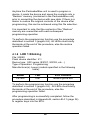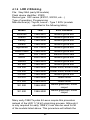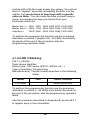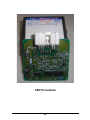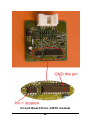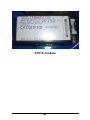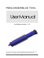
1
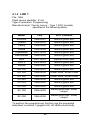
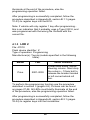
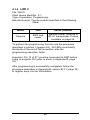
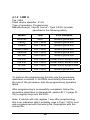
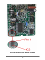
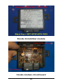
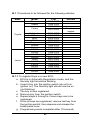
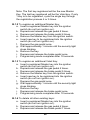
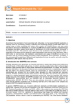
PENLOADERBLUE TOOL UserManual For Software Version: 1.10 The use of this apparatus is limited to legitimate and legal purposes for vehicle maintenance, in compliance with federal and state laws and regulations. i LED Illuminated File Selected LED 6 blinking Read and save to Restore memory LED 1 16bit (Toyota/Lexus) LED 2 47010 (Prius 01-03) LED 3 34010 (Sequoia 03+) LED 4 32bit (Toyota/Lexus) LED 5 Honda Red/Black LED 6 Restore last LED 1 blinking 50020 (LS400 97) LED 2 blinking 3key16bit (Early 98 Toy/Lex) LED 3 blinking FJ_S93C66 (FJ Cruiser) LED 4 blinking SaabCIM03_09 ii 1 INTRODUCTION 1 2 PRODUCT FEATURES 2 3 PENLOADERBLUE OPERATION 4 3.1 File Selection 4 3.2 Programming Operation 5 3.3 Step by Step Operation 6 3.4 Visual and Audio Cues 7 3.5 Restore Original Contents 9 3.6 Read and Save Content 9 4 4.1 PROGRAMMING FILE SELECTIONS IN DETAIL 10 General Operation 10 iii 1 Introduction The PenloaderBlue unit was designed to provide a tool that can be used to program memory devices installed on circuit boards. The tool is simple to use and requires no external computers, keypad entry devices, adaptor boards or cables. Features of the tool are: Small sized unit for hand held use 6 LEDs to display status Simple to use Programming options selected using a pushbutton switch Onboard probes with spring loaded protective cover, for programming 8 pin SOIC packages Supports Microwire (93 series) devices Powered by external 12V dc supply Includes dual LED lamps to illuminate area around device to be programmed Audio feedback to user 60 second auto power off when not in use Software is field updateable using a Windows PC and a serial cable Restore operation that can be used to restore contents of last device programmed. 1 2 Product Features Figure 1 – Penloader Unit 2 Item Description 1 On/Off button 2 12V dc input connector 3 START buttons 4 LED 1 5 LED 2 6 LED 3 7 LED 4 8 LED 5 9 LED 6 10 Neoprene grip 11 Spring probes 3 3 PenloaderBlue Operation This tool provides a set of programming functions to help the locksmith when programming new transponder keys. The operation of the PenloaderBlue unit can be split into 2 distinct procedures – operation and file selection; and the actual performance of the selected operation. 3.1 File Selection File selection is identified using the LEDs as shown in Table 1 below. On power up, the PenloaderBlue unit will flash LED 6, indicating that the selected option is to read an external device and save to the Restore memory (reference Table 1). Pressing the START button will advance the selection to the next position which is LED 1 ON. Each subsequent press of the START button will advance the file selection to the next in the sequence. When LED 6 is illuminated, a further push of the START button will advance to LED 1 flashing or blinking. When LED 4 blinking is reached, the next press of the START button will return the file selection to LED 1 ON (16bit). If the START button is not pressed after power up, the File Selection mode will time out in 5 seconds, and the PenloaderBlue unit will enter the programming mode. If the START button is pressed prior to timeout the file selection will advance to the next in the sequence and the timeout function will be reset to 3 seconds. Each subsequent press of the START button will reset the timeout to 3 seconds. Once the desired programming file has been selected, no further presses of the START button are required, and the file selection mode should be allowed to timeout. The time out of the file selection mode, and the transition of the unit to the programming mode, is marked by a short illumination (flash) of all LEDs simultaneously, along with a short 2 note audible chirp. 4 LED Illuminated File Selected LED 6 blinking Special state on power up only - read and save to Restore memory LED 1 ON LED 2 ON LED 3 ON LED 4 ON LED 5 ON LED 6 ON LED 1 blinking 16bit (Toyota/Lexus) 47010 (Prius 01-03) 34010 (Sequoia 03+) 32bit (Toyota/Lexus) HonFlash Restore original 50020 (LS400 97) LED 2 blinking 3key16bit (Early 98 Toy/Lex) LED 3 blinking FJ_S93C66 (FJ Cruiser) LED 4 blinking SaabCIM03_09 Table 1 – File selections (in order) 3.2 Programming Operation Once in programming mode the PenloaderBlue unit is ready to program an external device using the file selected (or for the LED 6 blinking option, read and save of data from an external device). Before the operation can take place the unit must be positioned over the device to be read or programmed, ensuring that the spring probes are making good contact with the legs on the memory device. Figure 2 below shows how to locate pin 1 on the 8 pin memory device. It is important that the spring probe identified as “1”, is in contact with Pin 1 on the 8 pin memory device. To start the operation press the START button once. There will be a short 1 second delay, then the operation will commence. During programming the unit will provide audio and visual cues as described in Table 3.2 below (page 5). 5 The operation will either end with success or failure, identified by the audio and visual cues. The PenloaderBlue unit will remain in programming mode, with the same file selected, until power is cycled. If the programming operation was not successful, it can be tried again without the need to go through the file selection procedure again. Figure 2 – Locator for Pin 1 Step by Step Operation 3.3 Thus, the basic operating procedure for using the PenloaderBlue unit is as follows: (i) (ii) Remove module containing memory device to be programmed, from the vehicle, and disassemble to provide access to the memory device to be programmed. Power up the PenloaderBlue unit. 6 (iii) (iv) (v) (vi) (vii) (viii) 3.4 Use START button to select the desired programming files (as indicated by the lit LED). After selecting the desired file, wait for all the LEDs to momentarily illuminate simultaneously with an audible chirp, signifying the end of the programming file selection period. Position the Penloader over the 8 pin memory device. Push the START button. Audio and visual cues will be provided during the programming operation. Listen for the audio cue identifying success or failure, and also signifying the end of the programming operation. Visual and Audio Cues When the PenloaderBlue unit is used to program an update into a memory device it will provide both visual and audio cues to the user. The following table defines these cues and their definition. 7 Visual Cue LED 1 and 2 illuminated. Audio Cue Definition None Low supply voltage. LED 5 and 6 illuminated. None None Faint ticking sound, with ticks approximately 1 second apart LEDs sequencing from center to outside, and back. Machine gun type sound All LEDs illuminated. Pseudo “charge” tune. No LEDs illuminated. Low tone held for 2 seconds. Overcurrent when powering up external device to be programmed. The Penloader is determining what type and size device it is currently positioned over. The Penloader is programming the external memory device. The VRFY operation was successful, and the data in the programmed part matches the data used in the program operation. An error occurred, or the Penloader could not determine the type of device, usually caused by bad connection to the chip Table 2 – Visual and audio cues 8 3.5 Restore Original Contents The PenloaderBlue unit contains a reserved “Restore” memory, which is used by the PenloaderBlue unit to save the contents of an external memory device before it overwrites it with new data. When programming an external memory device, and after the START button is pressed, and the PenloaderBlue unit has identified the external device to be programmed, the unit reads the contents of the external memory device, and saves it to the “Restore” memory. Should the user desire to restore the original contents of the external memory device after programming, this is made possible through the use of the Restore Original selection identified by LED 6 ON (ref Table 1, page 5). It is important to note that the “Restore” memory is overwritten by each subsequent programming of an external device. As a consequence, it is only possible to restore the contents of the last external memory device programmed. If the user reflashes the same device more than once “just to be sure it works”, he is essentially destroying the backup that was created the first time the device was reflashed. 3.6 Read and Save Content When the PenloaderBlue unit is powered up, it is put into a special state, indicated by LED 6 blinking. In this state it is possible to read the contents of an external 93C/LC series device and save it to the Restore memory. If the Start button is pressed within the timeout period, LED 1 will illuminate, and the unit will now cycle through the options as defined in Table 1. The only way to re-enter the read and save state again, once the START button has been pressed, is to power cycle the unit. 9 The data saved in the Restore memory can subsequently be used to write to other memory devices using the Restore function (LED 6). 4 Programming File Selections In Detail 4.1 General Operation The following sections describe the operation of the PenloaderBlue unit. 4.1.1 LED 6 Blinking File: None. Flash device identifier: Depends on manufacturer Type of operation: Read and save data Manufacturer(s): Any This setting is used to read data from an external device, and save the data to the Restore memory. When selected, and once the selection period has timed out, follow the procedure presented in section 3.3 (page 4), though in this case no data will be written to the external device. This operation is only presented as an option on first power up of the unit. Once the START button has been pressed to advance to the next possible operation, this read and save option is excluded from being selected again, until the next power cycle offers it again. Data read and saved using this operation, can be programmed into another device using the LED 6 selection as described in section 4.1.7 (page 15). Note that the data saved in the Restore memory will be overwritten by the next file write operation, LED 1 through LED 5. 10 4.1.2 LED 1 File: 16bit Flash device identifier: IC900 Type of operation: Programming Manufacturer(s): Toyota, Lexus – Type 1 ECU (models specified in the following table). Model Year ECU Location 4Runner 1998-2001 Behind glove box Avalon 1998-2003 Behind glove box Camry 1998-2000 Behind glove box Solara 1998-2000 Behind glove box Highlander 2001-2003 Behind glove box Landcruiser 1998-2000 Behind glove box MR2 2001-2003 Behind driver seat RAV 4 2002-2003 Behind glove box Sienna 1998-2003 Behind glove box ES 300 1998-2001 Behind glove box GS 300 1998-2000 Under hood, driver’s side GS 400 1998-2000 Under hood, driver’s side LS 400 1998-2000 Behind glove box LX 470 1998-2000 Behind glove box RX 300 1999-2003 Behind glove box SC 300 1998-2000 Below glove box, under carpet SC 400 1998-2000 Below glove box, under carpet To perform the programming function use the procedure described in section 3 (pages 4-8). All LEDs must briefly 11 illuminate at the end of the procedure, else the programming operation failed. After programming is successfully completed, follow the procedure described in Appendix B, section B.1.1 (pages 31-33) to register keys into the ECU. Note: If vehicle will only register 1 key after programming this is an indication that it probably uses a Type 2 ECU, and was programmed with the wrong file. Reflash with the correct file. 4.1.3 LED 2 File: 47010 Flash device identifier: IC Type of operation: Programming Manufacturer(s): Toyota (models specified in the following table). Model Prius Year Immo Location 2001-2003 Under dash board, above steering column. Must drop the column – 10mm bolt to release the bracket located in left corner behind roll bar. To perform the programming function use the procedure described in section 3 (pages 4-8). Pictures can be found on pages 27-28. All LEDs must briefly illuminate at the end of the procedure, else the programming operation failed. After programming is successfully completed, follow the procedure described in Appendix B, section B.2.1 (pages 33-34) to register keys into the Immobilizer. 12 4.1.4 LED 3 File: 34010 Flash device identifier: IC2 Type of operation: Programming Manufacturer(s): Toyota (models specified in the following table). Model Year Immo Location Sequoia 2003 and newer Behind cluster. Must be a 4D-67 transponder. Picture available on page 24. To perform the programming function use the procedure described in section 3 (pages 4-8). All LEDs must briefly illuminate at the end of the procedure, else the programming operation failed. Important: Pin 14 of IC1 must be connected to GND before trying to program IC2 (refer to photo in Appendix B, page 26). After programming is successfully completed, follow the procedure described in Appendix B, section B.3.1 (page 34) to register keys into the Immobilizer. 13 4.1.5 LED 4 File: 32bit Flash device identifier: IC900 Type of operation: Programming Manufacturer(s): Toyota, Lexus – Type 2 ECU (models specified in the following table). Model Year ECU Location 4Runner 2002 Behind glove box Camry 2001-2009 Behind glove box Solara 2001-2004 Behind glove box LandCruiser 2001-2002 Behind glove box Sequoia 2001-2002 Behind glove box ES 300 2002-2003 Behind glove box GS 300 2001-2003 Under hood, driver’s side GS 430 2001-2003 Under hood, driver’s side IS 300 2001-2003 Under hood, driver’s side LX 470 2001-2002 Behind glove box To perform the programming function use the procedure described in section 3. All LEDs must briefly illuminate at the end of the procedure, else the programming operation failed. After programming is successfully completed, follow the procedure described in Appendix B, section B.1.1 (page 3133) to register keys into the ECU. Note: If vehicle will only register 1 key after programming this is an indication that it probably uses a Type 1 ECU, and was programmed with the wrong file. Reprogram with the correct file. 14 4.1.6 LED 5 File: Red/Black Keys Type of operation: Programming Manufacturer(s): Honda (models specified in the following table). Model Year Immo Location NSX 1997 - 2004 Prelude 1997 - 2002 RL 1996 - 2004 Attached to steering column. Picture of unit on page 29. To perform the programming function use the procedure described in section 3 (pages 4-8). All LEDs must briefly illuminate at the end of the procedure, else the programming operation failed. You must have a properly coded RED key and BLACK key specifically made for the Penloader. You can create these keys yourself using a cloner (many can do this) and some HD106-T5 key blanks. The key values needed are as follows: Red Key = 89E9 1ECC 9721 FE03 Black Key = 8971 8F20 A574 FE03 Use an MVP, T-Code Pro, SDD, CodeSeeker, or similar programmer to initialize a Black Key after reflashing the immobilizer. 4.1.7 LED 6 File: Data from “Restore” memory. Flash device identifier: Depends on manufacturer Type of operation: Programming Manufacturer(s): Any This setting is used to restore the contents of a memory device to its value prior to programming. 15 Anytime the PenloaderBlue unit is used to program a device, it reads the device and saves the contents into a “Restore” memory (contained in the PenloaderBlue unit) prior to overwriting the device with new data. If there is a desire to restore the original contents of the device after programming, this can be achieved using this file selection. It is important to note that the contents of the “Restore” memory are overwritten with each subsequent programming operation To perform the programming function use the procedure described in section 3 (pages 4-8). All LEDs must briefly illuminate at the end of the procedure, else the restore operation failed. 4.1.8 LED 1 Blinking File: 50020 Flash device identifier: IC2 Device type: 93C series (93C01, 93C02, etc…) Type of operation: Programming Manufacturer(s): Lexus (models specified in the following table). Model Year ECU Location LS 400 1997 Behind glove box To perform the programming function use the procedure described in section 3 (pages 4-8). All LEDs must briefly illuminate at the end of the procedure, else the programming operation failed. After programming is successfully completed, follow the procedure described in Appendix B, section B.4.1 (page 36) to register keys into the ECU. 16 4.1.9 LED 2 Blinking File: 3key16bit (early 98 models) Flash device identifier: IC900 Device type: 93C series (93C01, 93C02, etc…) Type of operation: Programming Manufacturer(s): Toyota, Lexus – Type 1 ECU (models specified in the following table). Model Year ECU Location 4Runner 1998-2001 Behind glove box Avalon 1998-2003 Behind glove box Camry 1998-2000 Behind glove box Solara 1998-2000 Behind glove box Highlander 2001-2003 Behind glove box LandCruiser 1998-2000 Behind glove box MR2 2001-2003 Behind driver seat RAV4 2002-2003 Behind glove box Sienna 1998-2003 Behind glove box ES 300 1998-2001 Behind glove box GS 300 1998-2000 Under hood, driver’s side GS 400 1998-2000 Under hood, driver’s side LS 400 1998-2000 Behind glove box LX 470 1998-2000 Under hood RX 300 1999-2003 Under hood SC 300 1998-2000 Below glove box, under carpet SC 400 1998-2000 Below glove box, under carpet Many early 1998 Toyotas & Lexus require this procedure instead of the LED 1 (16 bit) virginizing process. Although it is only required for early 1998’s, it can also be used for all of the models listed above. This procedure will reflash the 17 module with a file that uses known key values. You will not have to “register” keys after reinstalling the ECU into the vehicle, but you do have to have keys with a specific value on them. You can make the keys yourself using a cloner or purchase the keys pre-cloned from your Penloader distributor. Master Key 1 = 7E2F 40FC 6000 0000 00FC C57E 0000 Master Key 2 = 7ED0 7CA0 2000 0000 0009 737E 0000 Valet Key = 7ECE 4585 6000 0000 00BF F67E 0000 To perform the programming function use the procedure described in section 3 (pages 4-8). All LEDs must briefly illuminate at the end of the procedure, else the programming operation failed. 4.1.10 LED 3 Blinking File: FJ_S93C66 Flash device identifier: Device type: 93C series (93C01, 93C02, etc…) Type of operation: Programming Manufacturer(s): Toyota (models specified in the following table). Model Year Immo Location FJ Cruiser Above glove box. To perform the programming function use the procedure described in section 3. All LEDs must briefly illuminate at the end of the procedure, else the programming operation failed. Use the procedure described in Appendix B, section B.5.1 to register keys in the immobilizer. 18 4.1.11 LED 4 Blinking File: SaabCIM03_09 Flash device identifier: Device type: 93C series (93C01, 93C02, etc…) Type of operation: Programming Manufacturer(s): Saab (models specified in the following table). Model Year Immo Location 93 2003-2009 Behind steering wheel. To perform the programming function use the procedure described in section 3. All LEDs must briefly illuminate at the end of the procedure, else the programming operation failed. After programming is successfully completed a GM tech2 dealer programmer with online subscription is required for key registration. Therefore it is recommended that the car be towed to a dealer, the CEM be reflashed at the dealer, then the dealer perform the key registration. 19 APPENDIX A User Manual – Circuit Board Photos 20 Base PenloaderBlue kit PenloaderBlue shown with available options 21 Toyota-Lexus 16bit ECU circuit board 22 Penloader installed on Toyota-Lexus 16bit ECU circuit board 23 2003 and later Sequoia (34010) immobilizer location behind instrument cluster. 24 34010 module 25 Circuit Board from 34010 module 26 47010 module 27 Circuit Board from 47010 module 28 Honda immobilizer module Honda module circuit board 29 APPENDIX B Toyota/Lexus Post Programming Procedures 30 B.1 Procedures to be followed for the following vehicles: Make Model 4Runner Avalon Year 1999-2002 1998-2003 1998-2002 Camry Toyota Lexus 2001-2003 Highlander LandCruiser MR2 RAV4 Sequoia Sienna Solara ES300 GS300 GS400 GS430 IS300 LS400 LX470 RX300 SC300 SC400 Remark 4 cylinder engine 2001-2003 1998-2002 2000-2003 2000-2003 2001-2002 1998-2003 1999-2003 1998-2003 1998-2003 1998-2000 2001-2003 2001-2003 1998-2000 1998-2002 1999-2003 1998-2000 1998-2000 B.1.1 To register Keys in a new ECU: a. ECU is in Automatic Registration mode, and the Security light should be blinking. b. Insert a key into the ignition switch (do not turn ignition on). The Security light should now be on (not blinking). c. The key is now registered. d. Remove key from the ignition switch. e. Repeat steps b through e if more keys are to be registered. f. Once all keys are registered, remove last key from the ignition switch, then depress and release the brake pedal once. g. Programming mode completes after 10 seconds. 31 Note: The first key registered will be the new Master Key. The last key registered will be the Valet key. If only 1 key is to be registered, cycle the single key through the registration process 4 or 5 times. B.1.2 To register an additional Master Key: a. Insert a registered Master key into the ignition switch (do not turn ignition on). b. Depress and release the gas pedal 5 times. c. Depress and release the brake pedal 6 times. d. Remove the Master key from the ignition switch. e. Insert new key to be registered into the ignition switch (do not turn ignition on). f. Depress the gas pedal once. g. Wait approximately 1 minute until the security light stops blinking. h. Remove the key. i. Depress and release the brake pedal once. j. Programming mode completes after 10 seconds. B.1.3 To register an additional Valet Key: a. Insert a registered Master key into the ignition switch (do not turn ignition on). b. Depress and release the gas pedal 4 times. c. Depress and release the brake pedal 5 times. d. Remove the Master key from the ignition switch. e. Insert new key to be registered into the ignition switch (do not turn ignition on). f. Depress the gas pedal once. g. Wait approximately 1 minute until the security light stops blinking. h. Remove the key. i. Depress and release the brake pedal once. j. Programming mode completes after 10 seconds. B.1.4 To delete all other existing keys: a. Insert a registered Master key into the ignition switch (do not turn ignition on). b. Depress and release the gas pedal 6 times. c. Depress and release the brake pedal 7 times. 32 d. Remove the Master key from the ignition switch. e. Insert new key to be registered into the ignition switch (do not turn ignition on). f. Depress the gas pedal once. g. Wait approximately 1 minute until the security light stops blinking. h. Remove the key. i. Depress and release the brake pedal once. j. Programming mode completes after 10 seconds. B.2 Procedure to be followed for the following vehicles: Make Toyota Model Prius Year 2001-2003 Remark B.2.1 To register Keys in a new ECU: a. Ensure there is no key in the ignition. b. While sitting in drivers seat, close all vehicle doors, but do not lock them. c. Insert first new Master key into the ignition switch. d. Wait 5 seconds, then remove key from ignition switch. e. Insert second new Master key into the ignition switch. f. Wait 5 seconds, then remove key from ignition switch. g. Insert new Valet key into the ignition switch. h. Wait 5 seconds, then remove key from ignition switch. i. All 3 keys should now trun off the theft light, but will no start the vehicle. j. Insert a Master Key into the ignition switch, and turn turn ignition switch on. a. Short OBD2 connector terminal 4 to terminal 13 using a wire or paper clip. a. Wait 30 minutes, then turn ignition switch off and remove shorting wire from OBD2. Programming mode is complete. Vehicle should now start with any of the 3 keys. 33 B.2.2 To register an additional Master or Valet Key: a. Ensure there is no key in the ignition. b. While sitting in drivers seat, close all vehicle doors, but do not lock them. c. Insert a registered Master key into the ignition switch. d. Quickly turn ignition switch ON then OFF 5 times. e. Quickly open, then close, the driver’s door 6 times. f. Remove the Master key from the ignition switch. g. Insert new key to be registered into the ignition switch (do not turn ignition on). This must be completed within 10 seconds of removing the Master key. h. Leave key in the ignition switch for a minimum of 60 seconds, until the Theft light goes out. i. Remove the key from the ignition switch. j. Key is now registered in ECU. B.3 Procedure to be followed for the following vehicles: Make Toyota Toyota Toyota Lexus Lexus Model Sequoia Camry Solara LS430 ES330 Year 2003+ 2001 - 2004 2003 - 2004 2004 2004 Lexus RX330 2004 Remark VIN starts with J or 2 B.3.1 To register 3 Keys (2 Master, 1 Valet) in a new Immobilizer: a. Ensure there is no key in the ignition. b. While sitting in drivers seat, close all vehicle doors, but do not lock them. c. Insert first Master key into the ignition switch and wait 5 seconds. d. Remove key and insert second Master key into the ignition switch and wait 5 seconds. 34 e. Remove key and insert Valet key into the ignition switch and wait 5 seconds. f. Remove key. a. The Immobilizer must be resynchronized with the ECU, else vehicle will not start. Insert a Master Key into the ignition switch, and turn ignition switch on (do not try to start the vehicle). b. Short OBD2 connector terminal 4 to terminal 13 using a wire or paper clip. c. Wait for 30 minutes. d. Remove shorting wire from OBD2 connector. e. Turn ignition switch off and remove key. f. Reinsert key and verify that vehicle can now be started. To register less than 3 Keys in a new Immobilizer: a. Ensure there is no key in the ignition. b. While sitting in drivers seat, close all vehicle doors, but do not lock them. c. Insert first Master key into the ignition switch and wait 5 seconds. d. Remove key. If required, insert a second key into the ignition switch, wait 5 seconds then remove key. e. Insert first Master key into the ignition switch. f. Quickly turn ignition switch ON then OFF 5 times. g. Remove key. h. The Immobilizer must be resynchronized with the ECU, else vehicle will not start. Insert a Master Key into the ignition switch, and turn ignition switch on (do not try to start the vehicle). i. Short OBD2 connector terminal 4 to terminal 13 using a wire or paper clip. j. Wait for 30 minutes. k. Remove shorting wire from OBD2 connector. l. Turn ignition switch off and remove key. m. Reinsert key and verify that vehicle can now be started. 35 B.4 Procedure to be followed for the following vehicles: Make Lexus Model LS400 Year 1997 Remark B.4.1 To register a new Master Key after installing a new ECU: a. While sitting in driver’s seat, close all vehicle doors, but do not lock them. b. Insert a working "Master" key into the ignition switch. c. Turn ignition switch ON then OFF. d. Remove key from ignition switch. e. Open, then close, the driver’s door. Programming mode is complete. B.4.2 To register an additional Master Key: a. Ensure there is no key in the ignition. b. While sitting in driver’s seat, close all vehicle doors, but do not lock them. c. Insert a working "Master" key in the ignition and turn lock to On 5 times. d. Open and shut the driver door 6 times. e. Remove the "Master key from the ignition. f. Insert the new in-programmed key in the ignition to the ON position for a few minutes until the security light goes out. g. Remove the key, open and shut the driver door once. The key is now programmed as a master. 36 B.5 Procedure to be followed for the following vehicles: Make Saab Model Year 2003-2009 Remark B.5.1 To register Keys in the Immobilizer – use AD t-code Pro or MV Pro: a. Go to type 5 under immo. section with key in the "on" position. b. Next menu you will see "Learn Key". c. After that has been completed key has been registered. Car will not start until the immo is married to the ECU. d. Use the black dongle provided in the kit to marry system. e. Turn key to "ON" and install the black dongle to the data port "OBDII". 37 38