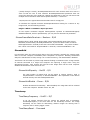
1
AVT GigE
Camera and Driver Attributes
Firmware 1.42
September 23, 2011
Allied Vision Technologies Canada Inc.
101-3750 North Fraser Way
Burnaby, BC
V5J 5E9 / Canada
Notes
1) This is the master document for all camera models. Not all attributes are
rd
available on all cameras or firmware versions. For 3 party users, see the camera
XML file. For PvAPI users, see the PvAttrIsAvailable function call.
2) For PvAPI users, attribute type is given: enum, float32, uint32, string, or
command. See the corresponding PvAttrEnum___, PvAttrFloat32___,
PvAttrUint32___, PvAttrString___, PvCommandRun calls.
3) R/W = attribute is read/write. R/C = attribute is read only and constant. R/V =
attribute is read only and volatile, can change at any time.
2
Camera Attributes
Camera Attributes affect settings on the camera itself – vs. Driver Attributes which affect
the host PvAPI driver.
Acquisition
Trigger
AcqEnd
AcqEndTriggerEvent – Enum – R/W
If AcqEndTriggerMode = SyncIn1/2, determines which SyncIn1/2 electrical
signal initiates trigger.
EdgeRising
EdgeFalling
EdgeAny
LevelHigh
LevelLow
rising edge trigger
falling edge trigger
rising or falling edge
active high signal
active low signal
AcqEndTriggerMode – Enum – R/W
Is the end of acquisition initiated by an external hardware trigger.
SyncIn1
SyncIn2
Disabled
trigger at SyncIn1 to be associated with this control
trigger at SyncIn2 to be associated with this control
no external trigger. Acquisition must be stopped with the
AcquisitionStop API command.
AcqRec
An AcqStart hardware trigger signal, or the AcquisitionStart command, must be received
before your AcqRec trigger. See AcquisitionMode = Recorder.
AcqRecTriggerEvent – Enum – R/W
If AcqRecTriggerMode = SyncIn1/2, determines which SyncIn1/2 electrical
signal initiates trigger.
EdgeRising
EdgeFalling
EdgeAny
LevelHigh
LevelLow
rising edge trigger
falling edge trigger
rising or falling edge
active high signal
active low signal
AcqRecTriggerMode – Enum – R/W
Is the recorder mode trigger event initiated by an external hardware trigger.
3
SyncIn1
SyncIn2
Disabled
trigger at SyncIn1 to be associated with this control
trigger at SyncIn2 to be associated with this control
no external trigger. Unlike AcqStart and AcqEnd, there is no
API command trigger option for a recording event.
AcqStart
Controls relating to the start of an acquisition stream. Frames are triggered within this
acquisition stream (see FrameStart).
AcqStartTriggerEvent – Enum – R/W
If AcqStartTriggerMode = SyncIn1/2, determines which SyncIn1/2 electrical
signal initiates trigger.
EdgeRising
EdgeFalling
EdgeAny
LevelHigh
LevelLow
rising edge trigger
falling edge trigger
rising or falling edge
active high signal
active low signal
AcqStartTriggerMode – Enum – R/W
Is the start of acquisition initiated by an external hardware trigger.
SyncIn1
SyncIn2
Disabled
trigger at SyncIn1 to be associated with this control
trigger at SyncIn2 to be associated with this control
no external trigger. Acquisition must be started with the
AcquisitionStart API command.
FrameRate – Float32 – R/W
When FrameStartTriggerMode is set to FixedRate, this control specifies the frame
rate.
FrameStart
Controls relating to the triggering of frames within an acquisition stream.
FrameStartTriggerDelay – Uint32 – R/W
Start-of-image is delayed FrameStartTriggerDelay microseconds after
receiving an external trigger event. This feature is only valid when
FrameStartTriggerMode is set to external trigger (i.e. SyncIn1, SyncIn2).
Useful when using a common trigger to synch with a strobe lighting source,
which will inherently have some fixed setup time
FrameStartTriggerEvent – Enum – R/W
If FrameStartTriggerMode = SyncIn1/2, determines which SyncIn1/2
electrical signal initiates trigger.
4
EdgeRising
EdgeFalling
EdgeAny
LevelHigh
LevelLow
rising edge trigger
falling edge trigger
rising or falling edge
active high signal
active low signal
FrameStartTriggerMode – Enum – R/W
Determines how an image is initiated once AcquisitionStart called, or
AcqStart hardware trigger set. For Freerun and FixedRate the first frame is
synchronized to AcquisitionStart/AcqStart trigger.
Freerun
SyncIn1
SyncIn2
FixedRate
Software
frame triggers generated on-camera, at maximum supported
frame rate depending on the exposure time and region of
interest size.
external trigger SyncIn1
external trigger SyncIn2
frame triggers generated on-camera, at frame rate defined by
FrameRate attribute.
software initiated frame trigger. See
FrameStartTriggerSoftware command.
FrameStartTriggerOverlap – Enum – R/W
Possible values: Off, PreviousFrame. When Off, any external trigger received
before FrameTriggerReady signal is high is ignored. When PreviousFrame,
any external trigger received before FrameTriggerReady is latched and used
to trigger the next frame. Default is Off.
FrameStartTriggerSoftware – Command
Triggers an image. Valid when FrameStartTriggerMode = Software.
AcquisitionAbort – Command
Software command to stop camera from receiving frame triggers, plus aborts any
currently exposing image.
AcquisitionFrameCount – Uint32 – R/W
Define the number of frames to capture in a limited sequence of images. Used with
AcquisitionMode = MultiFrame and Recorder. In Recorder mode, AcquisitionFrameCount
cannot exceed StreamHoldCapacity.
AcquisitionMode – Enum – R/W
Determine how many frame triggers the camera receives after acquisition start event.
Continuous
The camera will continuously receive frame triggers.
SingleFrame
The camera will only receive a single frame trigger event. Further
frame triggers will be ignored until acquisition is stopped and
restarted.
5
MultiFrame
The camera will receive AcquisitionFrameCount number of frame
triggers. Further frame triggers will be ignored until acquisition is
stopped and restarted.
Recorder
The camera will continuously capture images into camera memory, but
will not send them to the host until an AcqRec trigger signal is
received. Further AcqRec trigger events will be ignored until acquisition
is stopped and restarted.
This feature allows returning RecorderPreEventCount number of
frames before the trigger event, and AcquisitionFrameCount minus
RecorderPreEventCount frames after the trigger.
When AcqRec trigger is received, the currently imaging/aquiring image
will complete as normal, and then at least one more image will be
taken.
Camera memory is a circular buffer, once it is full, it starts overwriting
images.
AcquisitionStart – Command
Software command to start camera receiving frame
AcqStartTriggerMode = disabled. See FrameStartTriggerMode.
triggers.
Valid
when
AcquisitionStop – Command
Software command to stop camera from receiving frame
AcqEndTriggerMode = disabled. See FrameStartTriggerMode.
triggers.
Valid
when
RecorderPreEventCount – Uint32 – R/W
The number of images returned before the AcqRec trigger event, with
AquisitionFrameCount minus RecorderPreEventCount images being returned after the
trigger event. Valid only when AcquisitionMode equals Recorder.
Note: at least one image must be captured after the AcqRec trigger event. That is, you
cannot set RecorderPreEventCount = 1, AcquisitionFrameCount = 1.
ConfigFile
AVT's GigE cameras are capable of storing a number of user-specified configurations within the
camera's non-volatile memory. These saved configurations can be used to define the power-up
settings of the camera or to quickly switch between a number of predefined settings.
NOTE: Only camera attributes (those attributes listed in this document under the Camera
Attributes section) can be saved to a camera ConfigFile. Driver attributes cannot be saved.
ConfigFileIndex – Enum – R/W
The index number corresponding to the configuration set that you are currently working
with. Possible values: Factory, 1, 2, 3, 4, 5.
6
ConfigFileLoad – Command
Loads settings saved in camera non-volatile memory indicated by ConfigFileIndex to the
current camera settings.
ConfigFilePowerup – Enum – R/W
The saved configuration loaded when the camera powers up. Possible values: Factory, 1,
2, 3, 4, 5.
ConfigFileSave – Command
Saves the current camera settings to camera non-volatile memory indicated by
ConfigFileIndex. The Factory setting cannot be overwritten.
Controls
DSP
The automatic exposure, gain, WhiteBalance, and iris features can be configured to respond
only to a subregion within the image scene. This feature can be used to choose a subregion that
will 'meter' the rest of the image. This feature works like the region metering on a photographic
camera.
DSPSubregionBottom – Uint32 – R/W
Defines the bottom edge of the DSP subregion. Measured in pixels from the top
edge of the full image. Note: Currently defaults to a huge number much larger than
the maximum number of sensor rows.
DSPSubregionLeft – Uint32 – R/W
Defines the position of left edge of the DSP subregion. Measured in pixels from the
left edge of the full image. Defaults to zero.
DSPSubregionRight – Uint32 – R/W
Defines the right edge of the DSP subregion. Measured in pixels from the left edge
of the full image. Note: Currently defaults to a huge number much larger than the
maximum number of sensor columns.
DSPSubregionTop – Uint32 – R/W
Defines the top edge of the DSP subregion. Measured in pixels from the top edge of
the full image. Defaults to zero.
DefectMask
This feature is only available on the GE4000 and GE4900 cameras. The standard model of these
cameras use Class 2 sensors which can have column defects. The DefectMask replaces defective
7
columns with interpolated values based on neighboring columns. Class 1 and Class 0 sensors
are available for these cameras which do not require any column masking.
DefectMaskColumnEnable – Enum – R/W
Possible values: On, Off.
Exposure
Auto
NOTE: The camera must be acquiring images in AcquisitionMode = Continuous in order
for the auto algorithm to update.
Auto algorithms use information from the camera’s current image and apply the following
settings to the next image. Large changes in scene lighting may require several frames
for the algorithm to stabilize.
ExposureAutoAdjustTol – Uint32 – R/W
In percent, from 0 to 50.
Sets a tolerance in variation from
ExposureAutoTarget in which the auto exposure algorithm will not respond.
Can be used to limit exposure setting changes to only larger variations in
scene lighting.
ExposureAutoAlg – Enum – R/W
The following algorithms can be used to calculate auto-exposure:
Mean
The arithmetic mean of the histogram of the current image is
compared to ExposureAutoTarget, and the next image
adjusted in exposure time to meet this target. Bright areas are
allowed to saturate.
FitRange
The histogram of the current image is measured, and the
exposure time of the next image is adjusted so bright areas
are not saturated. Generally, the Mean setting is preferred.
ExposureAutoMax – Uint32 – R/W
In microseconds. This sets the upper bound to the exposure setting in
autoexposure mode. This is useful in situations where frame rate is
important. This value would normally be set to something less than
1x10^6/(desired frame rate).
ExposureAutoMin – Uint32 – R/W
In microseconds. This sets the lower bound to the exposure setting in
autoexposure mode.
ExposureAutoOutliers – Uint32 – R/W
8
Each unit represents 0.01%. When value is 1000, this equals 10%. The
percentage defines the total pixels from top of the distribution that are
ignored by the auto exposure algorithm.
ExposureAutoRate – Uint32 – R/W
In percent. Determines the rate at which the auto exposure function changes
the exposure setting.
ExposureAutoTarget – Uint32 – R/W
In percent. Controls the general lightness or darkness of the auto exposure
feature; specifically the target mean histogram level of the image, 0 being
black, 100 being white.
ExposureMode – Enum – R/W
Manual
The camera
parameter.
exposure
time
is
fixed
by
ExposureValue
Auto
The exposure time will vary continuously according to the
scene illumination. The Auto exposure function operates
according to the Auto and DSP controls
AutoOnce
A command. The exposure will be set once according to the
scene illumination and then remain at that setting even when
the scene illumination changes. The AutoOnce function
operates according to the Auto and DSP controls.
External
When ExposureMode is set to External the exposure time will
be controlled by an external signal appearing on SyncIn1 or
SyncIn2. In order for this feature to work, the parameter
FrameStartTriggerMode must be set to SyncIn1 or SyncIn2.
ExposureValue – Uint32 – R/W
In microseconds. The sensor integration time. 15000 corresponds to 15 ms
integration time, 1000 corresponds to 1 ms, etc.
Gain
Auto
NOTE: The camera must be acquiring images in AcquisitionMode = Continuous in order
for the auto algorithm to update.
Auto algorithms use information from the camera’s current image and apply the following
settings to the next image. Large changes in scene lighting may require 2-3 frames for
the algorithm to stabilize.
GainAutoAdjustTol – Uint32 – R/W
9
In percent, from 0 to 50. Sets a tolerance in variation from GainAutoTarget
in which the auto exposure algorithm will not respond. Can be used to limit
gain setting changes to only larger variations in scene lighting.
GainAutoMax – Uint32 – R/W
In dB. Sets the upper bound to the gain setting in Auto gain mode.
GainAutoMin – Uint32 – R/W
In dB. Sets the lower bound to the gain setting in Auto gain mode. Normally
this number would be set to zero.
GainAutoOutliers – Uint32 – R/W
Each unit represents 0.01%. When value is 1000, this equals 10%. The
percentage defines the total pixels from top of the distribution that are
ignored by the auto gain algorithm.
GainAutoRate – Uint32 – R/W
In percent. Determines the rate at which the auto gain function changes the
gain setting.
GainAutoTarget – Uint32 – R/W
In percent. Controls the general lightness or darkness of the Auto gain
feature. A percentage of the maximum GainValue.
GainMode – Enum – R/W
Manual
The camera gain is fixed by GainValue parameter.
Auto
The gain will vary continuously according to the scene
illumination. The Auto function operates according to the Auto
and DSP controls.
AutoOnce
A command. The gain will be set once according to the scene
illumination and then remain at that setting even when the
scene illumination changes. The AutoOnce function operates
according to the Auto and DSP controls.
GainValue – Uint32 – R/W
In dB. GdB = 20 log10(Vout/Vin). The gain setting applied to the sensor. Default gain
is zero, and gives the best image quality. However, in low light situations, it may be
necessary to increase the gain setting.
LensDrive
Open loop DC 3 axis lens control.
10
LensDriveCommand – Enum – R/W
Setting to any non-Stop value will execute the function for LensDriveDuration and
and then return to Stop.
Stop
IrisTimedOpen
IrisTimedClose
FocusTimedNear
FocusTimedFar
ZoomTimedIn
ZoomTimedOut
No action.
Open lens iris.
Close lens iris.
Shorten working distance.
Lengthen working distance.
Zoom in.
Zoom out.
LensDriveDuration – Uint32 – R/W
In ms. Duration of timed lens commands.
LensVoltage – Uint32 – R/V
In mV. Lens power supply voltage.
LensVoltageControl – Uint32 – R/W
Lens power supply voltage control. Set value as mV * 100001. E.g. 12 V =
1200012000. If a bad value is written this control resets to 0. This is done to
prevent users inadvertently setting an inappropriate voltage, possibly damaging the
lens. See lens documentation for appropriate voltage level.
Iris
NOTE: The camera must be acquiring images in AcquisitionMode = Continuous in order
for the auto algorithm to update.
All video-type auto iris lenses have a default reference voltage. When a voltage larger
than this reference voltage is applied to the lens, the iris closes. When a voltage is applied
less than this reference voltage, the iris opens. The auto iris algorithm calculates the
appropriate voltage, IrisVideoLevel, to apply to the lens, based on the information of the
current image. Large changes in scene lighting may require 2-3 frames for the algorithm
to stabilize.
IrisAutoTarget – Uint32 – R/W
In percent. Controls the general lightness or darkness of the auto iris feature;
specifically the target mean histogram level of the image, 0 being black, 100 being
white.
IrisMode – Enum – R/W
11
Sets the auto-iris mode.
Disabled
Video
VideoOpen
VideoClosed
Turn off the video auto-iris function.
Turn on the video auto-iris function.
Fully open the iris.
Full close the iris.
IrisVideoLevel – Uint32 – R/W
In 10 mV units. This attribute reports the strength of the video signal coming from
the camera.
IrisVideoLevelMax – Uint32 – R/W
In 10 mV units. Limits the maximum driving voltage for closing the lens iris.
Typically this will be 150, however it may vary dependent on the lens reference
voltage.
IrisVideoLevelMin – Uint32 – R/W
In 10 mV units. Limits the minimum driving voltage for opening the lens iris.
Typically this will be 0.
SubstrateVoltage
VsubValue – Uint32 – R/C
Factory use only. CCD Substrate Voltage value in mV units. Optimized at factory for
each sensor.
WhiteBalance
Auto
Auto algorithms use information from the camera’s current image and apply the following
settings to the next image. I.e. the camera must be acquiring images in order for the auto
algorithm to update. Large changes in scene lighting may require 2-3 frames for the
algorithm to stabilize.
WhitebalAutoAdjustTol – Uint32 – R/W
A threshold. This parameter sets a range of scene color changes in which the
automatic white balance will not respond. This parameter can be used to limit
whitebalance setting changes to only larger variations in scene color.
WhitebalAutoRate – Uint32 – R/W
In percent. Determines how fast the Auto White balance updates.
WhitebalMode – Enum – R/W
12
Manual
Auto white balance is off. White balance can be adjusted directly by
changing the WhitebalValueRed and WhitebalValueBlue parameters.
Auto
White balance will continuously adjust according to the current scene.
The Auto function operates according to the Auto and DSP controls
AutoOnce
A command. The white balance will be set once according to the scene
illumination and then remain at that setting even when the scene
illumination changes. The AutoOnce function operates according to the
Auto and DSP controls
WhitebalValueRed – Uint32 – R/W
Gain applied to all red pixels on the CCD, pre-interpolation. Expressed as a
percentage. 100% = no gain applied.
Note: there is no WhitebalValueGreen, as this is the luminance/reference channel.
To increase/decrease green, decrease/increase red+blue accordingly.
WhitebalValueBlue – Uint32 – R/W
Gain applied to all blue pixels on the CCD, pre-interpolation. Expressed as a
percentage. 100% = no gain applied.
Note: there is no WhitebalValueGreen, as this is the luminance/reference channel.
To increase/decrease green, decrease/increase red+blue accordingly.
EventControls
EventID
All the events supported by the camera:
EventAcquisitionStart – Uint32 – R/C
40000
EventAcquisitionEnd – Uint32 –R/C
40001
EventFrameTrigger – Uint32 – R/C
40002
EventExposureEnd – Uint32 – R/C
40003
EventAcquisitionRecordTrigger – Uint32 – R/C
40004
EventSyncIn1Rise – Uint32 – R/C
40010
EventSyncIn1Fall – Uint32 – R/C
40011
EventSyncIn2Rise – Uint32 – R/C
40012
13
EventSyncIn2Fall – Uint32 – R/C
40013
EventSyncIn3Rise – Uint32 – R/C
40014
EventSyncIn3Fall – Uint32 – R/C
40015
EventSyncIn4Rise – Uint32 – R/C
40016
EventSyncIn4Fall – Uint32 – R/C
40017
EventOverflow – Uint32 – R/C
65534
Always on. Cannot be turned off with EventSelector or EventsEnable1. Event occurs if
camera event buffer overflows, i.e. if host is unable to process/send acknowledgements
for events as quickly as events are generated from camera.
EventError – Uint32 – R/C
65535
Always on. Cannot be turned off with EventSelector or EventsEnable1. Event should
never occur, only returning in case of firmware failure requiring camera repair.
EventNotification – Enum – R/W
Turns the selected event notification On or Off.
EventSelector – Enum – R/W
Select a specific event to be enabled or disabled using EventNotification. Possible values:
AcquisitionStart
AcquisitionEnd
FrameTrigger
ExposureEnd
AcquisitionRecordTrigger
SyncIn1Rise
SyncIn1Fall
SyncIn2Rise
SyncIn2Fall
SyncIn3Rise
SyncIn3Fall
SyncIn4Rise
SyncIn4Fall
EventsEnable1 – Uint32 – R/W
Bitmask of all events. Bits correspond to last two digits of EventID. E.g. Bit 1 is
EventAcquisitionStart, Bit 2 is EventAcquisitionEnd, Bit 10 is EventSyncIn1Rise. This is an
alternative to setting each of the event individually using the EventNotification and
EventSelector method.
14
GigE
BandwidthCtrlMode – Enum – R/W
Select the desired mode of bandwidth control.
StreamBytesPerSecond
The default
mode of bandwidth control. See
StreamBytesPerSecond control for more information.
the
SCPD
Stream channel packet delay expressed in timestamp counter
units. This mode is not recommended.
Both
Implements a combination of control modes. This mode is not
recommended.
ChunkModeActive – Boolean – R/W
Possible values: TRUE, FALSE. Enables camera to send GigE Vision Standard Protocol
chunk data with an image. Currently implemented chunk data:
[Bytes
[Bytes
[Bytes
[Bytes
[Bytes
[Bytes
[Bytes
[Bytes
[Bytes
[Bytes
[Bytes
[Bytes
[Bytes
1 – 4]
5 – 8]
9 – 12]
13 – 16]
17 – 18]
19 – 20]
21 – 24]
25 – 28]
29 – 32]
33 – 36]
37 – 40]
41 – 44]
45 – 48]
acquisition count.
reserved. 0.
exposure value.
gain value.
sync in levels.
sync out levels.
reserved. 0.
reserved. 0.
reserved. 0.
reserved. 0.
reserved. 0.
chunk ID. 1000.
chunk length.
PvAPI users see tPvFrame.AncillaryBuffer.
NonImagePayloadSize – Unit32 – R/V
Size of chunk mode data, in bytes. If ChunkModeActive = FALSE, NonImagePayloadSize
= 0.
PayloadSize – Unit32 – R/V
Total size of payload in bytes. Payload = TotalBytesPerFrame + NonImagePayloadSize.
StreamBytesPerSecond – Uint32 – R/W
In Bytes/Sec. Moderates the data rate of the camera. This is particularly useful for
slowing the camera down so that it can operate over slower links such as Fast Ethernet
(100-speed), or wireless networks. It is also an important control for multi-camera
situations. When multiple cameras are connected to a single Gigabit Ethernet port
15
(usually through a switch), StreamBytesPerSecond for each camera needs to be set to a
value so that the sum of each camera’s StreamBytesPerSecond parameter does not
exceed the data rate of the GigE port. Setting the parameter in this way will ensure that
multiple camera situations work without packet collisions, i.e. data loss.
115,000,000 is the typical data maximum data rate for a GigE port.
To calculate the required minimum StreamBytesPerSecond setting for a camera in any
image mode, use the following formula:
Height x Width x FrameRate x Bytes per Pixel
If host reports occasional dropped frames/packets reported as StatFramesDropped/
StatPacketsMissed, with an optimized NIC, you may need to decrease this parameter.
StreamFrameRateConstrain – Boolean – R/W
Possible values: TRUE, FALSE. When TRUE, camera automatically limits frame rate to
bandwidth, determined by StreamBytesPerSecond, to prevent camera buffer overflows
and dropped frames. If FALSE, frame rate not limited to bandwidth – only sensor readout
time. Latter case useful for AcquisitionMode = Recorder, or StreamHoldEnable = On.
StreamHold
For controlling when the camera sends data to the host computer. Normally the camera sends
data to the host computer immediately after completion of exposure. Enabling StreamHold
delays the transmission of data, storing it in on-camera memory, until StreamHold is disabled.
This feature can be useful to prevent GigE network flooding in situations where a large number
of cameras connected to a single host computer are capturing a single event. Using the
StreamHold function, each camera will hold the event image data until the host computer
disables StreamHold for each camera in turn.
StreamHoldCapacity – Uint32 – R/V
The total number of images that can be stored in camera memory. Used in
AcquisitionMode = Recorder, or StreamHoldEnable = On. Dependent on the camera
internal memory size and TotalBytesPerFrame.
StreamHoldEnable – Enum – R/W
Enables StreamHold functionality. When disabled, the image data will be released
to the host computer. Possible values: On, Off.
Timestamp
TimeStampFrequency – Uint32 – R/C
In Hz. All images returned from the camera are marked with a timestamp.
TimeStampFrequency is the time base for the Timestamp function. The image
timestamp can be useful for determining whether images are missing from a
sequence due to missing trigger events.
TimeStampReset – Command
16
Reset the camera’s time stamp to 0.
TimeStampValueHi – Uint32 – R/V
Time stamp, upper 32-bit.
TimeStampValueLatch – Command
Command. Latch the value of the timestamp on the camera. Both
TimeStampValueHi and TimeStampValueLo are updated with the value read from
the camera.
TimeStampValueLo – Uint32 – R/V
Time stamp, lower 32-bit.
ImageFormat
ROI
Region of Interest. Defines a rectangular sub-region of the image. Selecting an ROI that is small
can increase the maximum frame rate and reduce the amount of image data. The following
parameters define the size and location of the ROI sub-region:
Height – Uint32 – R/W
In rows. The vertical size of the rectangle that defines the ROI.
RegionX – Uint32 – R/W
In pixels. The X position of the top-left corner of the ROI.
RegionY – Uint32 – R/W
In pixels. The Y position of the top-left corner of the ROI.
Width – Uint32 – R/W
In columns. The horizontal size of the rectangle that defines the ROI.
PixelFormat – Enum – R/W
The various pixel data formats the camera can output. Not all cameras have every mode.
Pixel Format
Bit
Depth*
Bytes
Per
On-Camera
Interpolation
Description
17
Mono8
8
Pixel
1
Mono16
Full
2
Bayer8
Bayer16
8
Full
1
2
No
No
Rgb24
8
3
Yes
Bgr24
8
3
Yes
Yuv411
8
1.5
Yes
Yuv422
8
2
Yes
Yuv444
8
3
Yes
Rgba32
8
4
Yes
Bgra32
8
4
Yes
Rgb48
Full
6
Yes
Mono12Packed
8
1.5
No
Bayer12Packed
8
1.5
No
Mono Cam: No
Color Cam: Yes
Mono Cam: No
Color Cam: Yes
Mono data.
Mono data. Data is LSbit aligned
within 16bits. E.g. for 12 bit
camera: 0000xxxx xxxxxxxx.
Raw color data.
Raw color data. Data is LSbit
aligned within 16bits. E.g. for 12
bit camera: 0000xxxx xxxxxxxx.
Color data. 3 consecutive bytes,
R, G, B, per pixel.
Color data. 3 consecutive bytes,
B, G, R, per pixel.
Color data. Full Y, limited UV, for
4 pixels extrapolated from 6
bytes.
Color data. Full Y, limited UV, for
2 pixels extrapolated from 4
bytes.
Color data. Full Y and UV, for 1
pixel extrapolated from 3 bytes.
Color data. 4 consecutive bytes,
R, G, B, 0, per pixel.
Color data. 4 consecutive bytes,
B, G, R, 0, per pixel.
Color data. 3 consecutive 16 bit
words, R, G, B, per pixel. Data is
LSbit aligned within 16bits. E.g.
for 12 bit camera: 0000xxxx
xxxxxxxx.
Mono data. 2 pixels of data every
3 bytes. Formatted as 11111111,
11112222, 22222222.
Raw color data. 2 pixels of data
every 3 bytes. Formatted as
11111111, 11112222, 22222222.
*Full bit depth is dependent on the camera A/D. See camera user manual. 8 bit depth = most
significant 8 bits of camera A/D.
TotalBytesPerFrame – Uint32 – R/V
Read only. The total number of bytes per image frame. Dependant on ROI, PixelFormat,
and Binning.
ImageMode
Binning is the summing of charge of adjacent pixels on a sensor, to give a lower resolution but
more sensitive image.
BinningX – Uint32 – R/W
The horizontal binning factor.
18
BinningY – Uint32 – R/W
The vertical binning factor. In most cases BinningX and BinningY would be set to equal
values.
Info
CameraName – String – R/W
Human readable camera name. E.g. “EngineRoomCam1”.
DeviceFirmwareVersion – String – R/C
Version of the Firmware the camera is running.
DeviceModelName – String – R/W
Human readable model name, such as “GE650”. Software should use the PartNumber and
PartVersion to distinguish between models.
DevicePartNumber – String – R/C
Manufacturer’s part number
DeviceSerialNumber – String – R/C
The Serial Number is not a unique identifier across models; software should use UniqueId
instead.
DeviceVendorName – String – R/C
Manufacturer’s name.
Firmware
Read only. What firmware is currently loaded on the camera.
FirmwareVerBuild – Uint32 – R/C
Build number.
FirmwareVerMajor – Uint32 – R/C
The major part of the Firmware version number (part before the decimal).
FirmwareVerMinor – Uint32 – R/C
The minor part of Firmware version number (part after the decimal).
19
Part
PartClass – Uint32 – R/C
Camera part class (manufacturer dependant).
PartNumber – Uint32 – R/C
Camera part number. Manufacturer part number for the camera model.
PartRevision – String – R/C
Camera revision. Part number revision level.
PartVersion – String – R/C
Camera version. Part number version level.
SerialNumber – String – R/C
Camera serial number.
Sensor
SensorBits – Uint32 – R/C
The sensor digitization bit depth.
SensorHeight – Uint32 – R/C
The total number of pixel rows on the sensor.
SensorType – Enum – R/C
Monochrome or Bayer-pattern color sensor type.
SensorWidth – Uint32 – R/C
The total number of pixel columns on the sensor.
UniqueID – Uint32 – R/C
The unique camera ID that differentiates the current camera from all other cameras.
IO
20
The control and readout of all camera inputs and outputs. The number of inputs and outputs will
depend on your camera model.
Strobe
Valid when any of the SyncOut modes are set to Strobe1. Strobe allows the added functionality
of duration and delay, useful when trying to sync a camera exposure to an external strobe.
1
Strobe1ControlledDuration – Enum – R/W
When enabled, the Strobe1Duration control is valid. Possible Values: On, Off.
Strobe1Delay – Uint32 – R/W
In microseconds. Delay of start of strobe signal.
Strobe1Duration – Uint32 – R/W
In microseconds. Duration of strobe signal.
Strobe1Mode – Enum – R/W
Associates the start of strobe signal with one of the following image capture
signals:
AcquisitionTriggerReady
FrameTriggerReady
FrameTrigger
Exposing
FrameReadout
Imaging
Acquiring
SyncIn1
SyncIn2
Active once the camera has been recognized
by the host PC and is ready to start
acquisition.
Active when the camera is in a state that will
accept the next frame trigger.
Active when an image has been initiated to
start. This is a logic trigger internal to the
camera, which is initiated by an external
trigger or software trigger event.
Active for the duration of sensor exposure.
Active at during frame readout, i.e. the
transferring of image data from the CCD to
camera memory.
Active during exposure and readout.
Active during an acquisition stream.
Active when there is an external trigger at
SyncIn1
Active when there is an external trigger at
SyncIn2
NOTE: Please refer to camera waveform diagrams provided in the camera
manuals for more detail information
SyncIn1
21
SyncIn1GlitchFilter – Uint32 – R/W
In nanoseconds. Ignores glitches on the SyncIn1 input line with pulse duration less
than set value. Note: setting this value increases latency of FrameTrigger by same
amount.
SyncIn2
Same as SyncIn1.
SyncInLevels – Uint32 – R/V
A bitmask, each bit corresponding to a specific SyncIn input. For example: 2 equals (0010)
which means SyncIn2 is high and all other Sync input signals are low.
SyncOut1
Controls the camera output 1. Can be used for synchronization with other cameras/devices or
general purpose outputs.
SyncOut1Invert – Enum – R/W
When enabled, reverses the polarity of the signal output by SyncOut1.
Possible values: On, Off.
SyncOut1Mode – Enum – R/W
Determines the type of output defined by SyncOut1:
GPO
AcquisitionTriggerReady
FrameTriggerReady
FrameTrigger
Exposing
FrameReadout
Acquiring
SyncIn1
SyncIn2
Strobe1
configured to be a general purpose output,
control
of
which
is
assigned
to
SyncOutGpoLevels
Active once the camera has been recognized
by the host PC and is ready to start
acquisition.
Active when the camera is in a state that will
accept the next frame trigger.
Active when an image has been initiated to
start. This is a logic trigger internal to the
camera, which is initiated by an external
trigger or software trigger event.
Active for the duration of sensor exposure.
Active at during frame readout, i.e. the
transferring of image data from the CCD to
camera memory.
Active during a acquisition stream.
Active when there is an external trigger at
SyncIn1
Active when there is an external trigger at
SyncIn2
The output signal is controlled according to
Strobe1 settings.
22
Note: Refer to camera waveform diagrams provided in the camera manual for
more detailed information.
SyncOut2/3/4
Same as SyncOut1.
SyncOutGpoLevels – Uint32 – R/W
GPO output levels. A bitfield. Bit 0 is sync-out 0, bit 1 is sync-out 1, etc.
23
Driver Attributes
Driver Attributes affect the host PvAPI driver – vs. Camera Attributes which affect settings
on the camera itself. Driver Attributes cannot be saved to a camera ConfigFile.
GigE
Ethernet
DeviceEthAddress – String – R/C
The physical MAC address of the camera.
HostEthAddress – String – R/C
The physical MAC address of the host network card on which the camera is reached.
IP
DeviceIPAddress – String – R/C
The current IP address of the camera.
HostIPAddress – String – R/C
The current IP address of the host network interface.
GvcpRetries – Uint32 – R/W
Gvcp = GigE Vision Control Protocol. The maximum number of resend requests that the
host will attempt when trying to recover a lost control packet.
Gvsp
Gvsp = GigE Vision Streaming Protocol.
GvspLookbackWindow – Uint32 – R/W
Size of the look back window, in packets, when determining if a stream packet is
missing.
When a stream packet arrives out of order, the driver skips back
GvspLookbackWindow packets to see if the packets previous to this point have all
arrived. If not, a resend is issued. A lower value allows the driver less time to
assemble out-of-order packets, a larger value allows the driver more time. If the value
is set too low, the driver will issue unnecessary resends. If the value is set too high
and a packet truly is missing, the driver will issue a resend but the camera may no
24
longer have the required packet in its resend buffer and the packet will be dropped.
The ideal value is system dependent.
GvspResentPercent – Float32 – R/W
Maximum of missing stream packets that will be requested from the camera if they
are detected missing.
GvspRetries – Uint32 – R/W
The maximum number of resend requests that the host will attempt when trying to
recover a lost stream packet.
GvspSocketBufferCount – Enum – R/W
Number of buffers to be used by the network socket. Only applicable when not
using the Filter Driver.
Possible values: 256,512,1024,2048,4096,8192
GvspTimeout – Uint32 – R/W
End of stream timeout, in milliseconds.
HeartbeatInterval – Uint32 – R/W
In milliseconds. On PvCameraOpen, the PvAPI driver sends heartbeat packets to
the camera every HeartbeatInterval milliseconds. This parameter should not require
adjustment.
HeartbeatTimeout – Uint32 – R/W
In milliseconds. On PvCameraOpen, the PvAPI driver sends heartbeat packets to
the camera. If a heartbeat packet is not received within HeartbeatTimeout, the
camera assumes the host has called PvCameraClose or is dead, and closes its
stream and control channel. This parameter may need to be increased if stepping
through code in a debugger, as this prevents the PvAPI driver from sending
heartbeat packets.
Multicast
Multicast mode allows the camera to send image data to all hosts on the same subnet as the
camera. The host computer that first enables multicast mode is the master, and controls all
camera parameters. All other hosts / instances are the monitors, and can view image data only.
NOTE: Most GigE switches support a maximum PacketSize of 1500 in Multicast mode.
MulticastEnable – Enum – R/W
Enables Multicast mode. Possible values: On, Off.
25
Note: In order to enable this, the camera must not be streaming.
MulticastIPAddress – String – R/W
Set the multicast IP address.
PacketSize – Uint32 – R/W
In Bytes. Determines the Ethernet packet size. Generally speaking this number should be
set to as large as the network adaptor will allow. If this number is reduced, then CPU
loading will increase. These large packet sizes are called Jumbo Packets/Frames in
Ethernet terminology. If your GigE network adaptor does not support Jumbo
Packets/Frames of at least 8228 Bytes (the camera default on power up), then you will
need to reduce PacketSize parameter to match the maximum supported by your network
adaptor.
A PacketSize of 1500 is a safe setting which all GigEthernet network cards support.
Note: If you are seeing all “black images”, or all frames reported as StatFramesDropped
and zero images reported as StatFramesCompleted, you will likely need to decrease this
parameter.
Stats
StatDriverType – Enum – R/V
Standard
Filter
The default network card driver is being used only.
The AVT filter driver is being used in conjunction with the default
network card driver. Using the Filter driver will reduce the load on the
host CPU.
StatFilterVersion – String – R/C
Version of the filter driver.
StatFrameRate – Float32 – R/V
Frame rate of the camera.
StatFramesCompleted – Uint32 – R/V
The number of camera images returned to the PvAPI frame queue successfully.
PvAPI programmers note: this stat does not increment if no frames queued.
Use tPvFrame.FrameCount for a counter of exactly which image the camera is returning.
StatFramesDropped – Uint32 – R/V
The number of frames returned to the PvAPI frame queue with one or more dropped
packet within.
26
PvAPI programmers note: this stat does not increment if no frames queued.
Use tPvFrame.FrameCount for a counter of exactly which image the camera is returning.
StatPacketsErroneous – Uint32 – R/V
The number of improperly formed packets. If this number is non-zero, it suggests a
possible camera hardware failure.
StatPacketsMissed – Uint32 – R/V
The number of packets missed since the start of imaging.
StatPacketsReceived – Uint32 – R/V
The number of packets received since the start of imaging.
StatPacketsRequested – Uint32 – R/V
The number of resend requests since the start of imaging. When an expected packet is
not received by the driver, it is recognized as missing and the driver requests the camera
to resend it.
StatPacketResent – Uint32 – R/V
The number of packets resent by the camera and received by the host, since the start of
imaging.
27
Contacting Allied Vision Technologies
• Technical information:
http://www.alliedvisiontec.com
• Support:
[email protected]
Allied Vision Technologies GmbH (Headquarters)
Taschenweg 2a
07646 Stadtroda, Germany
Tel.: +49.36428.677-0
Fax.: +49.36428.677-28
e-mail: [email protected]
Allied Vision Technologies Canada Inc.
101-3750 North Fraser Way
Burnaby, BC, V5J 5E9, Canada
Tel: +1 604-875-8855
Fax: +1 604-875-8856
e-mail: [email protected]
Allied Vision Technologies Inc.
38 Washington Street
Newburyport, MA 01950, USA
Toll Free number +1-877-USA-1394
Tel.: +1 978-225-2030
Fax: +1 978-225-2029
e-mail: [email protected]
28