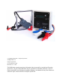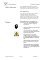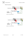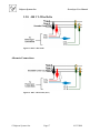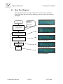
1
Powerlyzer
Power Quality Monitor
Operators Guide
October 2008
Valquest Systems Inc.
351 S. Sherman, St. # 100
Richardson, Tx. 75081
© CopyRight 2004-2009 – Valquest Systems Inc.
All Rights Reserved
Valquest Systems Inc.
351 S. Sherman, St.#100
Richardson, Tx. 75081
This Publication contains proprietary information that is protected by copyright and licensing
agreements. No part of this publication may be reproduced, transcribed, stored in a retrieval
system, translated to any language or computer language, or transmitted in any form whatsoever
without the prior written consent of Valquest Systems Inc.
Valquest Systems Inc.
Powerlyzer User Manual
Table of Contents
1.0
1.1
2.0
2.1
2.2
2.3
2.4
2.5
3.0
3.1
3.2
3.2.1
3.2.2
3.2.3
3.2.4
3.2.5
3.2.6
3.2.7
3.2.8
3.2.9
3.3
4.0
4.1
4.2
4.3
4.4
4.5
4.6
4.7
4.8
4.9
Introduction....................................................................................................................... 8
Powerlyzer Variants ......................................................................................................... 8
Overview of Features........................................................................................................ 9
Power Meter .................................................................................................................. 9
Power Quality Monitor................................................................................................. 9
Trend Recorder............................................................................................................. 9
Manual Operator Controls ........................................................................................ 10
Powerlyzer Companion Software.............................................................................. 10
Voltage/Current Input Cables & Connections......................................................... 11
Input Voltage Configurations .................................................................................... 11
Input Connections....................................................................................................... 12
120 VAC/Single Phase (Volts Only) .......................................................................... 12
120/240 V Split Phase.................................................................................................. 13
120/208 V 4-Wire Y..................................................................................................... 13
139/240 V 4-Wire Y..................................................................................................... 14
240 V 3-Wire Delta...................................................................................................... 14
240 V 4-Wire Delta...................................................................................................... 16
277/480 V 4-Wire Y..................................................................................................... 16
480 V 3-Wire Delta...................................................................................................... 17
480 V 4-Wire Delta...................................................................................................... 18
Automatic Voltage/Current Checks.......................................................................... 19
Display Menu................................................................................................................... 19
Menu System Operation................................................................................................. 19
Basic Flow Diagram........................................................................................................ 20
Reading the Voltage Display .......................................................................................... 21
Reading the Meter Display............................................................................................. 21
Parametrics Menu........................................................................................................... 21
Setup Menu...................................................................................................................... 23
Setup – (Date & Time).................................................................................................... 25
Setup – Elect. Configuration (Voltage) ......................................................................... 25
Setup – Elect. Configuration (CT Current Ratio) ....................................................... 27
4.9.1 Current Transducer with mA/A CT Output .............................................................. 27
4.9.2 Current Transducer with mV/A CT Output .............................................................. 29
4.10 Setup – Elect. Configuration (Current Input Range).................................................. 31
4.10.1 Current Transducer with mA/A CT Input Range ................................................... 31
4.10.2 Current Transducer with mV/A CT Input Range ................................................... 32
4.11 Setup – Elect. Configuration (Line Frequency) ........................................................... 33
4.12 Setup – Elect. Configuration (V-I Phase Offset) .......................................................... 34
4.13 Setup - Unit ID ................................................................................................................ 35
4.14 Record Mode ................................................................................................................... 36
5
Self-Test ............................................................................................................................... 38
6
Powerlyzer Features ........................................................................................................... 39
©Valquest Systems Inc.
Page 3
10/13/2008
Valquest Systems Inc.
Powerlyzer User Manual
7
Recording Parameters ........................................................................................................ 39
8
Environmental Specifications ............................................................................................ 39
9
Recommended & Optional Accessories .................................................................... 40
9.1
AC Current Transformers/Probes (Current Output) ............................................. 40
9.2
AC Current Transformers/Probes (Voltage Output).............................................. 41
9.3
Mounting Accessories (Optional) ............................................................................... 42
10
About Valquest Systems ............................................................................................. 44
©Valquest Systems Inc.
Page 4
10/13/2008
Valquest Systems Inc.
Powerlyzer User Manual
Table of Figures
Figure 1 Display & Controls........................................................................................................ 10
Figure 2 AC Line Cord ................................................................................................................. 11
Figure 3 Multi-Voltage Cable....................................................................................................... 11
Figure 4 Input Connections.......................................................................................................... 11
Figure 5 120/240 V Split Phase .................................................................................................... 13
Figure 6 120/208 V 4-Wire Y..................................................................................................... 13
Figure 7 139/240 V 4-Wire Y...................................................................................................... 14
Figure 8 240 V 3-Wire Delta ....................................................................................................... 14
Figure 9 240 V 3-Wire Delta (Alt-1) ........................................................................................... 15
Figure 10 240 V 3-Wire Delta (Alt-2) ......................................................................................... 15
Figure 11 240 V 4-Wire Delta ..................................................................................................... 16
Figure 12 277/480 V 4-Wire Y.................................................................................................... 16
Figure 13 480 V 3-Wire Delta ...................................................................................................... 17
Figure 14 480 V 3-Wire Delta (Alt-1) ......................................................................................... 17
Figure 15 480 V 3-Wire Delta (Alt-2) ......................................................................................... 18
Figure 16 480 V 4-Wire Delta ..................................................................................................... 18
Figure 17 Version Display ........................................................................................................... 20
Figure 18 Voltage Menu .............................................................................................................. 20
Figure 19 Power Menu................................................................................................................. 20
Figure 20 Parametric Menu ......................................................................................................... 20
Figure 21 Setup Menu.................................................................................................................. 20
Figure 22 Parametrics Menu (Yes) ............................................................................................. 22
Figure 23 Parametrics (Phase V-I)............................................................................................... 23
Figure 24 Parametrics (kW,kVAr,kVA) ...................................................................................... 23
Figure 25 Parametrics .................................................................................................................. 23
Figure 26 Setup (Yes) .................................................................................................................. 24
Figure 27 Date Setup/View Display ............................................................................................. 25
Figure 28 Time Setup/View Display ............................................................................................ 25
Figure 29 Voltage Configuration ................................................................................................. 26
Figure 30 Sample CT Ratio Settings ........................................................................................... 28
Figure 31 Sample CT Ratio Settings ........................................................................................... 30
Figure 32 Current Input Range .................................................................................................... 31
Figure 33 Current Input Range .................................................................................................... 32
Figure 34 Line Frequency Settings .............................................................................................. 33
Figure 35 V-I Phase Offset Settings ............................................................................................ 34
Figure 36 Unit ID Setting ............................................................................................................. 35
Figure 37 Voltage/Meter Displays............................................................................................... 37
Figure 38 Record Mode Off........................................................................................................ 37
Figure 39 Erase Data (No) ........................................................................................................... 37
Figure 40 Erase Data (Yes).......................................................................................................... 37
Figure 41 Record Mode (On)....................................................................................................... 37
Figure 42 Self Test Menu ............................................................................................................ 38
Figure 43 Self Test Version ......................................................................................................... 38
©Valquest Systems Inc.
Page 5
10/13/2008
Valquest Systems Inc.
Powerlyzer User Manual
Figure 44 Self Test Result............................................................................................................ 38
Figure 45 Self Test - Bit Status..................................................................................................... 38
Figure 46 Pole Mounting Kit ....................................................................................................... 42
Figure 47 Powerlyzer w/ Pole Mounting Plate ............................................................................ 42
Figure 48 Magnetic Mounting Kit ............................................................................................... 43
Figure 49 Powerlyzer w/ Magnetic Mounting Kit....................................................................... 43
Figure 50 Wall Mounting Kit ....................................................................................................... 43
Figure 51 Powerlyzer w/ Wall Mounting Kit .............................................................................. 43
©Valquest Systems Inc.
Page 6
10/13/2008
Valquest Systems Inc.
Safety Considerations
Powerlyzer User Manual
It is recommended that this product and related
documentation be reviewed for familiarization with
safety markings and instructions before operation.
Before Applying Power
Verify that the product shows no signs of physical
damage that may impair proper operation.
Verify that the Cables & Accessories (Voltage
probes/Current Transformers) to be used are in good
working condition and that they do not impose any
safety hazard such as exposure to electrical shock.
Warnings
When OPERATING or CONNECTING the
Powerlyzer to a VOLTAGE/CURRENT Source:
- Always Wear Protective Goggles or
Safety Glasses
- Always wear Industrial Grade Electrically
Insulated Gloves
- NEVER CONNECT the Powerlyzer to
Service with a Maximum Nominal Voltage
of 480 Volts Phase-to-Phase
- NEVER CONNECT any Current
Clamps/Probes/other accessories to
the Current Inputs that will produce more
than 1000 milliAmps RMS (1 Amp RMS
Max)
- NEVER CONNECT Voltmeter Probes or
Test Leads to the Powerlyzer Current
Inputs
- NEVER CONNECT the Neutral (White)
voltage lead to an UNGROUNDED Phase
unless the service is an UNGROUNDED 3WIRE DELTA
©Valquest Systems Inc.
Page 7
10/13/2008
Valquest Systems Inc.
Powerlyzer User Manual
1.0 Introduction
The Powerlyzer is a Recording Test Meter based upon the architecture of the Motorola 68HCxx
micro-controller. It is used to measure and compute various AC signal characteristics and/or
derivative AC signal components. Signal characteristics such as Voltage Blink, Voltage/Current
Level, Power Usage, Harmonic Analysis are just a few of the measurements within its
capabilities. The Powerlyzer is a small, rugged and lightweight instrument; making transportability easy for use in temporary installations where short term or periodic monitoring is
necessary. The primary intended use for the Powerlyzer is within the residential and industrial
voltage range of 120 VAC to 480 VAC. Front Panel operational controls and accessible
connector interfaces make the Powerlyzer simple to setup and operate.
The Powerlyzer is compatible with a wide selection of Voltage and Current Clamps allowing it
to function in a diverse set of operating environments. These capabilities along with its feature
rich and friendly operating environment make the Powerlyzer a versatile and economical
instrument used to measure, record and analyze various power systems and their associated
characteristics.
With an optional personal computer or laptop having a Microsoft™ Windows 2000, XP, or later
based operating system and the Powerlyzer companion software, users can exchange data
between the computer and the Powerlyzers internal memory for configuration, setup or data
recording and analysis. The companion software is written using Microsoft Visual Basic™ and
features the same look and feel of other windows based visual menu driven environments. The
companion software also provides the user with the ability to visually examine the signal
characteristics using tables, charts and graphs presenting the information needed to understand
and make recommendations for corrective action and improved system performance.
1.1 Powerlyzer Variants
The Powerlyzer is supplied to clients in 2 unique configurations based upon the type of Current Transformer (CT)
input. One configuration supports CT’s which provide a
current output (mA/A), the other supports CT’s which provide
a voltage output (mV/A). To Verify the particular input type,
refer to the unit labels and/or refer to the Version number
within the Powerlyzer.
CT Current Output Mode – Version 3.3.x
CT Voltage Output Mode – Version 3.3.y
(where x is even digit and y is odd digit)
©Valquest Systems Inc.
Page 8
10/13/2008
Valquest Systems Inc.
Powerlyzer User Manual
2.0 Overview of Features
2.1 Power Meter
Using internal and proprietary algorithms the Powerlyzer is able to sample,
capture and record the input signal waveforms for both voltage and current over a
given time interval. The system displays the following parameters:
Parameters for 1,2 or 3 Phase Circuits
Voltage
kW and kWH
kVA
Power Factor
Phase Rotation
Current
kVAr and kVArH
Phase Angle
Line Frequency
2.2 Power Quality Monitor
The user has the ability to set and control the Powerlyzer to Record input signal
data. This data is written/stored in the internal memory of the Powerlyzer
eliminating the need for external storage or recording devices. Some of the Types
of Data that are recorded are as follows:
Blinks
Brown-outs
3 Types of Min-Max Information
Capture Voltage/Current Waveforms
Calculates Harmonics (to the 63rd)
2.3 Trend Recorder
A computer having an RS-232 connection is is
required to setup the trend recorder
parameters. (Refer to the Software Companion
Guide for details)
No Computer is required to manually Start and
Stop the Trend Recorder.
The user has the ability to setup and control the time interval of the measurement
values shown below. The interval periods are as follows:
©Valquest Systems Inc.
Page 9
10/13/2008
Valquest Systems Inc.
Powerlyzer User Manual
Interval (In Minutes)
1
2
5
15
2.4 Manual Operator Controls
Controlling the Powerlyzer is simple and easy using the display driven menu
system. When power is applied to the unit, the 16 character x 2 line lcd display
panel will provide information to the user. There are 2 user input controls which
allow the user to manually communicate with the unit. These controls consist of a
rotating switch and a momentary pushbutton switch. By using these 2 controls
the user can follow the pre-programmed menu system and select the appropriate
choices for the type of application or setup condition needed.
Figure 1 Display & Controls
2.5 Powerlyzer Companion Software
The companion software provides an extensive set of features and tools that make
operator examination of signal characteristics, trend recordings and signal data
analysis easy and convenient. Refer to the attached Powerlyzer Companion
Software Users Guide for detailed information.
©Valquest Systems Inc.
Page 10
10/13/2008
Valquest Systems Inc.
Powerlyzer User Manual
3.0 Voltage/Current Input Cables & Connections
The Powerlyzer is shipped with 2 voltage cables. One cable is for connecting the
unit to a standard 120/60Hz ac outlet. The second cable features a set of Class III
1000v/20A alligator style clamps at one end to allow the user to connect the unit
to a multitude of operating environments. Cables connections to the unit utilize a
7-pin circular connector for ease of interchangeability. Current Transformers are
connected using standard Banana Plugs to the Banana jacks located on the bottom
of the Powerlyzer.
Figure 3 Multi-Voltage Cable
Figure 2 AC Line Cord
Figure 4 Input Connections
3.1 Input Voltage Configurations
Along with the many other features, the Powerlyzer requires no additional power
connections or special supplies. The design allows it to work readily with most
common lower AC voltage ranges. Power for the unit is supplied by the phase A
voltage input line so external power sources are eliminated. The voltage
configurations currently supported are as follows:
120 V Single Phase
120/240 Split Phase
120/208 4-Wire Y
139/240 4-Wire Y
240 3-Wire Delta
©Valquest Systems Inc.
240 4-Wire Delta
277/480 4-Wire Y
480 3-Wire Delta
480 4-Wire Delta
Page 11
10/13/2008
Valquest Systems Inc.
Powerlyzer User Manual
3.2 Input Connections
If you have not read the Warnings and safety
information found on Page 7 please do so
before continuing!!!
When using the multi-phase power cable, use Standard Connection chart for each
voltage lead to in order make quick and easy identification of each conductor
phase. This will ensure proper connections to your power service.
Standard Connection Chart
Black Conductor
Red Conductor
Blue Conductor
White Conductor
Phase A
Phase B
Phase C
Neutral
When using the current probes it will be necessary to
make sure that correct polarity is observed for proper
operation!!! If the readings are negative, it will be
necessary to reverse the CT on the conductor to
obtain the correct polarity resulting in valid
measurement data!!!
3.2.1 120 VAC/Single Phase (Volts Only)
Connect the 120 VAC wall plug cord to the 7 pin circular connector on
the bottom right of the Powerlyzer.
Plug the cord into a wall socket.
©Valquest Systems Inc.
Page 12
10/13/2008
Valquest Systems Inc.
Powerlyzer User Manual
3.2.2 120/240 V Split Phase
Figure 5 120/240 V Split Phase
3.2.3 120/208 V 4-Wire Y
Figure 6 120/208 V 4-Wire Y
©Valquest Systems Inc.
Page 13
10/13/2008
Valquest Systems Inc.
Powerlyzer User Manual
3.2.4 139/240 V 4-Wire Y
Figure 7 139/240 V 4-Wire Y
3.2.5 240 V 3-Wire Delta
Figure 8 240 V 3-Wire Delta
©Valquest Systems Inc.
Page 14
10/13/2008
Valquest Systems Inc.
Powerlyzer User Manual
Alternate Connections:
Figure 9 240 V 3-Wire Delta (Alt-1)
Figure 10 240 V 3-Wire Delta (Alt-2)
©Valquest Systems Inc.
Page 15
10/13/2008
Valquest Systems Inc.
Powerlyzer User Manual
3.2.6 240 V 4-Wire Delta
Figure 11 240 V 4-Wire Delta
3.2.7 277/480 V 4-Wire Y
Figure 12 277/480 V 4-Wire Y
©Valquest Systems Inc.
Page 16
10/13/2008
Valquest Systems Inc.
Powerlyzer User Manual
3.2.8 480 V 3-Wire Delta
Figure 13 480 V 3-Wire Delta
Alternate Connections:
Figure 14 480 V 3-Wire Delta (Alt-1)
©Valquest Systems Inc.
Page 17
10/13/2008
Valquest Systems Inc.
Powerlyzer User Manual
Figure 15 480 V 3-Wire Delta (Alt-2)
3.2.9 480 V 4-Wire Delta
Figure 16 480 V 4-Wire Delta
Note: The Powerlyzer treats a 3-wire delta service as a 2-phase (separated by 60
degrees) system with a Neutral. The current readings are adjusted by +/- 30
degrees to compensate for the fact that the voltages are not in phase with the
currents. The Powerlyzer automatically detects the phase rotation to determine
which phase to add 30 degrees to and from which to subtract 30 degrees.
©Valquest Systems Inc.
Page 18
10/13/2008
Valquest Systems Inc.
Powerlyzer User Manual
3.3 Automatic Voltage/Current Checks
The Powerlyzer automatically checks for voltages
and currents that exceed measurable limits
causing waveform clipping. If waveform clipping
is detected, a ^ symbol will appear after the word
Meter ^ in the Meter display. If this appears
check the Parametric values to determine the
source of the problem. The two possibilities will
be that the Configuration is incorrect or the
Current Input Range is set too low.
The Powerlyzer checks for consistent alignment of
current clamps. If all phases do not show the
same power flow direction, a ? symbol will appear
after the word Meter ? in the Meter display. If
this symbol appears check that all current clamps
are oriented in the same direction relative to the
load. Adjust clamps as required.
4.0 Display Menu
4.1 Menu System Operation
The 16x2 LCD display on the front panel provides the operator with the information about the options, selections and data for the instrument. The information is
contained within a pre-programmed menu system making the setup and configuration quick, easy and consistent. The operator moves through the menu
system via two controls; a rotating switch (Modify) which provides the paths and
selections through the menu, and momentary switch (Enter) which by pressing
will select or confirm the choice selected by the operator. This information is
then passed to the microcontroller and the appropriate actions are taken in
response to the operators commands.
©Valquest Systems Inc.
Page 19
10/13/2008
Valquest Systems Inc.
Powerlyzer User Manual
4.2 Basic Flow Diagram
The following illustration provides a high level look at the basic menu flow.
Each of the menu processes will be discussed in greater detail in the following
paragraphs.
Power Unit ON
Displayed
ONLY at
Power ON
Figure 17 Version Display
Display Indicates
Company Name
Software Revision
Figure 18 Voltage Menu
Voltage Information
Meter Information
(kW & kWH)
Figure 19 Power Menu
Parametrics
Figure 20 Parametric Menu
Setup
Figure 21 Setup Menu
©Valquest Systems Inc.
Page 20
10/13/2008
Valquest Systems Inc.
4.3
Powerlyzer User Manual
Reading the Voltage Display
The voltage display is used to display the all of the voltages currently being
measured. This is based upon the setup configuration. If a single phase is
monitored, only that phase will be displayed. If multiple phases are being
monitored, each of the multiple phases will be displayed.
4.4
Reading the Meter Display
The Meter display is used to display the kW parameters. Refer to to the following
illustration for an explaination of the display readout.
Instantaneous kW
Peak kWH
Peak kW Demand
The consumption and demand values are zeroed when the
unit is placed into the Record Mode.
4.5 Parametrics Menu
The Parametrics menu to provides the user with detailed information specific to
each phase being tested. The information obtained from the Parametrics menu is
as follows:
Line Voltage (each Phase)
Line Current (each Phase)
kW, kVAr, kVa (each Phase)
Power Factor (P-Ftr)
©Valquest Systems Inc.
Page 21
Phase Angle (each Phase)
3 Phase Rotation (ABC or CBA)
Neutral Current
10/13/2008
Valquest Systems Inc.
Powerlyzer User Manual
Power Unit ON
Display Indicates
Company Name
Software Revision
Voltage Information
Meter Information
(kW & kWH)
Parametrics
Press
Enter
No
Enter
Parametrics?
Rotate Modify Knob
To YES
Figure 22 Parametrics Menu (Yes)
©Valquest Systems Inc.
Page 22
10/13/2008
Valquest Systems Inc.
Powerlyzer User Manual
Parametrics Menu (Continued)
The parametric information below displays Phase A information base upon the
current setup. When the setup condition specifies more than a single phase the
additional phase information will also be present in sub-sequent displays as well
as the composite information.
Enter Parametrics Menu
Rotate the Modify knob
to view the desired
information for each
Phase. Pressing Enter
will display the data for
the next phase.
Rotate Modify to
continue viewing
the Information
Figure 23 Parametrics (Phase V-I)
No
Exit
Parametrics?
Figure 24 Parametrics (kW,kVAr,kVA)
Press Enter To EXIT
Parametrics Menu
Figure 25 Parametrics
(Power Factor, Phase Angle)
4.6 Setup Menu
The Setup menu provides the user a means in which to configure the Powerlyzer
for a specific test and measurement configuration. This must be performed
properly for the test data to have accurate and meaningful information. The
Powerlyzer Setup menu provides the user with the option of changing or selecting
the following parameters:
Date
Time (24 Hr Military Format)
Voltage Selection
CT Input Ratio
©Valquest Systems Inc.
Page 23
Current Input Range
Line Frequency
Voltage-Current Offset Values
Unit ID
10/13/2008
Valquest Systems Inc.
Powerlyzer User Manual
There are 2 methods which may be used to enter
the SETUP menu.
The first method is to follow the selected menu
paths on the display until the SETUP menu is
presented. Rotate the MODIFY knob to obtain a
YES indication and press the ENTER switch.
The second and more direct method is to PRESS
& HOLD the ENTER key for a minimum of 2
seconds.
Power Unit ON
Display Indicates
Company Name
Software Revision
Voltage Information
Meter Information
(kW & kWH)
Parametric
Press
Enter
Setup
No
Enter
Setup?
Figure 26 Setup (Yes)
Rotate Modify Knob
To YES
©Valquest Systems Inc.
Page 24
10/13/2008
Valquest Systems Inc.
4.7
Powerlyzer User Manual
Setup – (Date & Time)
Time displayed in Military Time (24 Hour)
Enter Setup Menu
Display Indicates
Date
Figure 27 Date Setup/View Display
Press Enter for 2
Seconds
Cursor appears under
Month (Mo)
Rotate Modify to
change (Mo) or press
Enter go to Day (Day)
Rotate Modify to
change (Day) or press
Enter to go to Year
(Yr).
Rotate Modify to
change (Yr) or press
Enter to continue
No
Display Indicates
Time
Figure 28 Time Setup/View Display
No
Press Enter for 2
Seconds
Cursor appears under
Hour (Hr)
Rotate Modify to
change (Hr) or press
Enter to go to Minutes
(Min)
Rotate Modify to
change (Min) or press
Enter to go to
Seconds (Sec).
Rotate Modify to
change (Sec) or press
Enter to continue
4.8
Date
Correct?
Time
Correct?
The Date & Time are used for
accurate Trend Recording and
should be set before starting a
Recording Session if they are
found to be incorrect!!!
Display Indicates
Configuration
Exit Setup Menu
Setup – Elect. Configuration (Voltage)
©Valquest Systems Inc.
Page 25
10/13/2008
Valquest Systems Inc.
Powerlyzer User Manual
The electrical configuration settings describe the type of service that the
Powerlyzer will be monitoring. The following illustration provides setup
instructions.
Enter Setup Menu
Display Indicates
Date
Display Indicates
Time
Display Indicates
Voltage Configuration
No
Rotate Modify to
select the correct
voltage configuration.
Is
Configuration
Correct?
Display Indicates
Correct Voltage
Configuration
Press Enter to save
setting and continue
Exit Setup Menu
Figure 29 Voltage Configuration
Settings
©Valquest Systems Inc.
Page 26
10/13/2008
Valquest Systems Inc.
Powerlyzer User Manual
4.9 Setup – Elect. Configuration (CT Current Ratio)
As discussed before the Powerlyzer is sold in two variants for different types of
Current Transducer (CT) outputs. These types either provide an output having a
mA/A output signal or a mV/A output signal. Please refer to the appropriate
section below for your particular Powerlyzer model.
4.9.1
Current Transducer with mA/A CT Output
The CT Current Ratio is normally the CT Ratio of the amp
probe being used. A typical value is 1000 or 1000:1.
However, when monitoring the second-ary of a large CT, this
number is the arithmetic product of the CT ratio and the
current ratio of the amp probe.
Example: If you have a 1000:1 amp probe and are
monitoring the secondary of an 800:5 CT, the
Effective Current Ratio would be 1000 X 160 =
160,000. You would most likely use 0-5 mA or 010mA Input Current Range.
The Input Current Range must be set such that the secondary
current of the CTs does not exceed the range. A lower range
improves resolution. If the range is too low, the current
waveform will be clipped.
Example: You are directly monitoring a system that is running
about 160 amps. If you are using 1000:1 current clamps you
would most likely use the 0-250 mA setting since the current
into the Powerlyzer will be about 160 mA.
If you don’t know the current, set the Input Current Range to
0-1000 mA. Read the current, the go back and set the Input
Current Range to a reasonable value.
©Valquest Systems Inc.
Page 27
10/13/2008
Valquest Systems Inc.
Powerlyzer User Manual
Enter Setup Menu
Display Indicates
Date
Display Indicates
Time
Display Indicates
Correct Voltage
Configuration
Display Indicates
CT Current Ratio
Configuration
No
Rotate Modify to select
the correct CT Ratio
configuration.
(Minimum = 1000:1)
(Maximum = 999000:1)
Is CT
Current Ratio
Correct?
Display Indicates
Correct CT Ratio
Configuration
Press Enter to save
setting and continue
Figure 30 Sample CT Ratio Settings
Exit Setup Menu
©Valquest Systems Inc.
Page 28
10/13/2008
Valquest Systems Inc.
4.9.2
Powerlyzer User Manual
Current Transducer with mV/A CT Output
The CT Current Ratio on CT’s having a mV/A output will
require the user to set the CT Ratio based upon there specific
type of CT.
Many of the Rope CTs having an adjustable range switch will
require the Powerlyzer to have a 1:1 CT Ratio to obtain
accurate readings. If your CT is a single output range with a
mV/A then the Powerlyzer should be set to a ratio of 1000:1
for accurate readings.
©Valquest Systems Inc.
Page 29
10/13/2008
Valquest Systems Inc.
Powerlyzer User Manual
Enter Setup Menu
Display Indicates
Date
Display Indicates
Time
Display Indicates
Correct Voltage
Configuration
Display Indicates
CT Current Ratio
Configuration
No
Is CT
Current Ratio
Correct?
Figure 31 Sample CT Ratio Settings
Rotate Modify to select
the correct CT Ratio
configuration.
(Minimum = 1:1)
(Maximum = 999000:1)
Display Indicates
Correct CT Ratio
Configuration
Press Enter to save
setting and continue
Exit Setup Menu
©Valquest Systems Inc.
Page 30
10/13/2008
Valquest Systems Inc.
Powerlyzer User Manual
4.10 Setup – Elect. Configuration (Current Input Range)
Refer to the appropriate section below for specific input range setup conditions
for your particular Powerlyzer model.
4.10.1 Current Transducer with mA/A CT Input Range
Enter Setup Menu
Display Indicates
Date/Time/Voltage
Display Indicates
Current Input Range
No
Rotate Modify to select
the correct Current Input
Range.
Is Current
Input Range
Correct?
Display Indicates
Correct Current
Input Range
Press Enter to save
setting and continue
Exit Setup Menu
©Valquest Systems Inc.
Page 31
Figure 32 Current Input Range
Settings
10/13/2008
Valquest Systems Inc.
Powerlyzer User Manual
4.10.2 Current Transducer with mV/A CT Input Range
Enter Setup Menu
Display Indicates
Date/Time/Voltage
Display Indicates
Current Input Range
No
Rotate Modify to select
the correct Current Input
Range.
Is Current
Input Range
Correct?
Display Indicates
Correct Current
Input Range
Press Enter to save
setting and continue
Figure 33 Current Input Range
Settings
Exit Setup Menu
©Valquest Systems Inc.
Page 32
10/13/2008
Valquest Systems Inc.
Powerlyzer User Manual
4.11 Setup – Elect. Configuration (Line Frequency)
The line frequency can be set for either 50 or 60 Hz. Most US electrical circuits
use 60 Hz.
Enter Setup Menu
Display Indicates
Date/Time/Voltage
Current Input Range
Display Indicates
Line Frequency
No
Rotate Modify to select
the correct Line
Frequency (50/60Hz)
Is Line
Frequency
Correct?
Figure 34 Line Frequency Settings
Display Indicates
Correct
Line Frequency
Press Enter to save
setting and continue
Exit Setup Menu
©Valquest Systems Inc.
Page 33
10/13/2008
Valquest Systems Inc.
Powerlyzer User Manual
4.12 Setup – Elect. Configuration (V-I Phase Offset)
The Voltage-Current (I) offset can be adjusted from 0° - 359° either positive or
negative.
Enter Setup Menu
Display Indicates
Date/Time/Voltage
Current Input Range
Line Frequency
Display Indicates
V-I Phase Offset
No
Rotate Modify to select
the correct V-I Phase
Offset
(Minimum 0)
(Maximum 359)
Is V-I
Phase Offset
Correct?
Figure 35 V-I Phase Offset Settings
Display Indicates
Correct
V-I Phase Offset
Press Enter to save
setting and continue
Exit Setup Menu
©Valquest Systems Inc.
Page 34
10/13/2008
Valquest Systems Inc.
Powerlyzer User Manual
4.13 Setup - Unit ID
The Unit ID provides a specific identifier to each Powerlyzer. This is beneficial
when more than one Powerlyzer is available for use in a system.
Enter Setup Menu
Display Indicates
Date/Time/Voltage
Current Input Range
Line Frequency
V-I Phase Offset
Display Indicates
Unit ID
Figure 36 Unit ID Setting
No
Rotate Modify to select
the correct Unit ID
(Minimum -1)
(Maximum-999999)
Is
Unit ID
Correct?
Display Indicates
Correct
Unit ID
Press Enter to save
setting and continue
Exit Setup Menu
©Valquest Systems Inc.
Page 35
10/13/2008
Valquest Systems Inc.
Powerlyzer User Manual
4.14 Record Mode
Record mode is used to record the measured electrical Trend data taken by the Powerlyzer
and then stores this data in the Powerlyzers internal memory. The nature and amount of
data depends upon the Recording Parameters set within the Powerlyzer Companion
Software. This data can be downloaded and analyzed using the Powerlyzer Companion
Software. This manual will only deal with setting up the Powerlyzer to start/stop data
recording, refer to the Powerlyzer Companion Software for details on configuring the
Recording parameters as well as downloading the Trend data and performing analysis.
The user can enter Recording mode from the Voltage and/or Metering Display menus.
All Trend Data, Blink Data and Min/Max Data is
erased when the Record mode is entered. Make sure
that the data has been downloaded prior to
initializing the Record Mode Session or the current
data will be Lost!!!
©Valquest Systems Inc.
Page 36
10/13/2008
Valquest Systems Inc.
Powerlyzer User Manual
Power Unit ON
Voltage Information
is displayed
Record
Data?
No
Meter Information
(kW & kWH)
is displayed
Record
Data?
Figure 37 Voltage/Meter Displays
Rotate the Modify
knob to enter the
Record Menu.
Press Enter
Erase
Data?
Figure 38 Record Mode Off
No
Figure 39 Erase Data (No)
No
Parametrics
Setup
©Valquest Systems Inc.
Rotate the Modify knob to
select YES Erase Data?
Press Enter to start
Recording.
The Data will be erased
and Recording will begin
Press Enter to Stop
Recording.
After Stopping, rotate the
Modify knob to exit the
recording menu.
Voltage/Meter information
will be present.
Page 37
Figure 40 Erase Data (Yes)
Figure 41 Record Mode (On)
10/13/2008
Valquest Systems Inc.
Powerlyzer User Manual
5 Self-Test
The Powerlyzer has a built-in Self-Test operation to verify and check the internal
functionality of the unit.
This routine does not need to be performed for
normal setup and use. It is intended to be
used only when a suspected malfunction of
the unit has occurred or as necessary to
verify that the unit is still functioning
correctly.
Enter Setup Routine
Exit Setup
Enter
Setup?
No
Figure 42 Self Test Menu
Rotate Modify Knob to
the YES position.
Figure 43 Self Test Version
Rotate Modify Knob to
the Run Self Test Menu
Figure 44 Self Test Result
Press Enter to Initiate
Self Test Routine
Figure 45 Self Test - Bit Status
Press Reset to Exit the
Self Test Routine
©Valquest Systems Inc.
Page 38
10/13/2008
Valquest Systems Inc.
Powerlyzer User Manual
6 Powerlyzer Features
Parameter Measurement
Voltage
Current
Blink Voltage
Blink Duration
Power Loss
Blink / Power Loss Storage
Phase Angle
KW
KVAr
KVA
Power Factor
Line Frequency
Phase Rotation
Harmonics
Range
0 to 550 VAC
0 to 9999 Amps
0 to 108 VAC
½ to 4 Sec
4 Sec or Greater
200 Events
0 to 359.5°
-9999 to +9999 kW
-9999 to +9999 kVAr
0 to 9999 kVA
- 0.5% to +0.5%
50Hz or 60Hz
ABC or ACB
st
1 through 37th
Resolution
+/- 0.2%
+/- 0.5%
+/- 2.0%
½ Cycle
1 Second
+/- 0.5°
+/- 0.5%
+/- 0.5%
+/- 0.5%
+/- 0.5%
+/- 0.02 Hz
7 Recording Parameters
Trend Parameters
Derived Parameters
Number of Measured Phases
Trend Period (Minutes)
Max Records
Blink / Power Loss Storage
Min-Max Voltage Storage
Voltage, Current, Phase Angle
KW, kVAr, kVA, Power Factor
1, 2, or 3
15, 5, 2, 1
65536
200 Events
4 Second and 1 Minute
8 Environmental Specifications
Condition
Range
Operating Temperature
Humidity (Non-Condensing)
Operating Voltage
Input Measurement Current Range
Input Measurement Current Range
Power Usage
Enclosure
©Valquest Systems Inc.
Page 39
-40°F to 165°F
0 to 100%
95 to 530 VAC
0 to 1000 mA/A
0 to 3000 mV/A
½ Watt
Nema 4
10/13/2008
Valquest Systems Inc.
Powerlyzer User Manual
9 Recommended & Optional Accessories
Utilizing Standard device connections, the versatility of the PowerLyzer is unmatched and
compatible with various voltage clamps and styles as well as current transformers. The
following is a list of commonly recommended accessories.
The Powerlyzer is supplied in both a voltage input
configuration and a current input configuration. Check your
configuration prior to connecting any new devices for
compatibility. Failure to provide the proper voltage/current
input type may result in damage to the equipment and create
an unsafe electrical condition. Failure to set the correct input
range and input ratio may also damage unit.
9.1 AC Current Transformers/Probes (Current Output)
Standard Powerlyzer (Current Model)
Mfr.
Flex-Core
Flex-Core
Flex-Core
Flex-Core
Flex-Core
©Valquest Systems Inc.
Model #
MN106
MN213
MD303
SR604
JM800A
AC Range
150A
200A
500A
1000A
1000A
Page 40
DC Range
-
Output Signal
1mA/A
1mA/A
1mA/A
1mA/A
1mA/A
10/13/2008
Valquest Systems Inc.
Powerlyzer User Manual
9.2 AC Current Transformers/Probes (Voltage Output)
Standard Powerlyzer (Voltage Model)
Mfr.
Model #
AC Range
DC Range
Flex-Core
MR411
Flex-Core
MR521
Flex-Core
SR661
60A
600A
150A
1500A
-
Fluke
i200
Fluke
i400
Fluke
I3000
40A
400A
100A
1000A
20A Peak
200A Peak
2000A
Peak
1A
200A
40A
400A
30A
300A
3000A
Flex-Core
LEM-Flex
RR3035-24
RR3035-36
RR3035-48
30A
300A
3000A
-
©Valquest Systems Inc.
Page 41
-
Output
Signal
10mV/A
1mV/A
10mV/A
1mV/A
100mV/A
10mV/A
1mV/A
100mV/A
10mV/A
10mV/A
1mV/A
100mV/A
10mV/A
1mV/A
100mV/A
10mV/A
1mV/A
10/13/2008
Valquest Systems Inc.
Powerlyzer User Manual
9.3 Mounting Accessories (Optional)
(Optional) mounting brackets are available for the Powerlyzer. These brackets
allow the powerlyzer to be installed safely in areas where it is impractical or
unsafe to leave the powerlyzer in a stand-alone or “just sitting there” condition.
9.1.1
Pole/Structure Mounting Kit
The Pole Mounting Kit consists of a Single Sturdy Brushed Aluminum Plate
and hardware which will allow the plate to be fastened to the back of the
Powerlyzer. The Bracket extends beyond the Powerlyzer on each end
allowing for connection to a Pole or other suitable structure using Lag bolts
or similar fastening devices. The Plate can be mounted on the Powerlyzer in
both a vertical position or a horizontal position.
Figure 46 Pole Mounting
Kit
©Valquest Systems Inc.
Page 42
Figure 47 Powerlyzer w/ Pole
Mounting Plate
10/13/2008
Valquest Systems Inc.
9.1.2
Powerlyzer User Manual
Magnetic Mounting Kit
The Magnetic Mounting Kit consists of a set of (4) powerful magnetic
fasteners and hardware. The magnets are fastened to the back of the Powerlyzer in each corner. This arrangement provides an optimal solution where
there are adequate metal surfaces and/or equipment or facilities to place the
Powelyzer in a safe operating mode.
Figure 48 Magnetic Mounting Kit
Figure 49 Powerlyzer w/ Magnetic
Mounting Kit
9.1.3
Wall Mounting Kit
The Wall Mounting Kit consists of a set of (4) small steel Wall Mounting
brackets and hardware. Fasten the steel brackets to the back of the
Powerlyzer in any or all corners. This arrangement provides an optimal
solution where a magnetic mount or pole mount arrangement is not practical
and limited facilities exist. Connection to the facility may be made via any
number of methods based upon what is available or practical for the situation
(ie. Tie Wraps/Nails/Screws/etc.)
Figure 50 Wall Mounting Kit
Figure 51 Powerlyzer w/ Wall
Mounting Kit
©Valquest Systems Inc.
Page 43
10/13/2008
Valquest Systems Inc.
Powerlyzer User Manual
10 About Valquest Systems
Valquest Systems
What Sets Us Apart
We Stand for building strong Client relationships and providing
exceptional service and products.
Our Vision is to be a leading provider of monitoring and control equipment to small
electric utilities on a national basis.
Our Purpose is to improve the efficiency of electricity transmission and
distribution in America.
Our Commitment is to create optimal long-term approaches for our
Clients needs.
Valquest Systems, Inc.
351 S. Sherman Street, Suite 100
Richardson, TX 75081
Voice: 972-234-2954
Fax:
972-238-9501
EMail: [email protected]
Website: www.valquest.com
©Valquest Systems Inc.
Page 44
10/13/2008