1
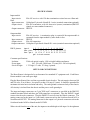
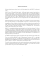
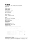
ROTOR ROUTER
DMX512 DIGITAL PATCH BAY
OWNERS MANUAL
Doug Fleenor Design
396 Corbett Canyon Road
Arroyo Grande, CA 93420
(805) 481-9599
revision 1.0
May, 2000
TABLE OF CONTENTS
Product Description
2
Specifications
3
Setup and Connections
3
Operation
4
Line Termination
4
Technical Details
5
Troubleshooting
6
About the Company
6
Warranty
6
PRODUCT DESCRIPTION
Doug Fleenor Design specializes in customizing, so your particular unit may differ in some respects
from the product described in this Owner's Manual. This manual will describe the standard product
and call attention to common customized features.
The Rotor-Router is a DMX512 distribution system featuring up to 12 inputs and an unlimited
number of outputs. A system typically consists of an input module and one or more output modules.
Both modules are 1.7"h x 19"w x 12"d and are normally rack mounted. A plexiglass security cover
is included to prevent accidental switch changes.
The input module features 12 optically isolated DMX512 inputs on 5 pin XLR connectors (terminal
block connections are optional). Each input has two front panel indicators (power and signal). The
input module feeds the twelve DMX signals to up to thirty output modules (or more on special
order) via a 25 pin D connector (DB-25P). All connections and the power cord are on the rear panel.
The output module features 12 optically isolated DMX512 outputs on 5 pin XLR connectors
(terminal block connections are optional). Each output has two front panel indicators (power and
signal) and a front panel twelve position rotary switch (to select from one of twelve inputs). The
output module receives the twelve DMX signals from the input module via a 25 pin D connector
(DB-25P). All connections and the power cord are on the rear panel.
When rack mounted, the 25 pin D connectors on the input and output modules line up in a vertical
column; a 25 conductor ribbon-wire assembly joins the modules. When input and output modules
are in different locations, 12 pair 120 Ohm data cable is used to connect the modules. Each module
has its own power cord.
Split modules may be ordered on a custom basis that have mixed inputs and outputs in a single
chassis. Such a unit can have any combination of up to twelve inputs/outputs. For example: 3
inputs 9 outputs (pictured above), 6 inputs 6 outputs, 11 inputs 1 output, etcetera).
The Digital Multiplex Combine Unit is an interface device which combines multiple DMX512
lighting control signals into a single DMX512 output. The standard product compares the level for
each dimmer from the various inputs and sends the higher level. This method of combining control
signals is often referred to as "pile-on" or "highest takes precedence". Customized software to
provide other functions is optional.
2
SPECIFICATIONS
Input module
Input circuit:
Data.
Input connectors:
Output circuit:
EIA-485 receiver with 120 ohm termination resistor between +Data and -
Gold plated 5 pin male Neutrik D-1 series (terminal connections optional).
EIA-485 transmitter with 60 ohm series (source) termination (DMX512
signals on a non-standard connector).
Output connector: DB-25P.
Output module
Input circuit:
EIA-485 receiver. A termination plug is required if the output module is
separated from the input module by more than six feet.
Input connector:
DB-25P
Output circuit:
EIA-485 transmitter
Output connectors: Gold plated 5 pin female Neutrik D-1 series (terminal connections optional)
DB-25 pinouts:
input #:
1 2 3 4 5 6 7 8 9 10 11 12
data - pin #: 2 3 4 5 6 7 8 9 10 11 12 13
data + pin #: 14 15 16 17 18 19 20 21 22 23 24 25
pin 1 is circuit common
Common specifications:
Isolation:
2500 volt optical coupler, 1500 volt split bobbin transformer
Power input:
100 - 120 volts, 50/60 hertz, 12 watts (208 - 240 volt optional)
Size & Weight:
1.74" high, 19" wide, 12" deep, 9 pounds
SETUP AND CONNECTIONS
The Rotor-Router is designed to be rack mounted in a standard 19" equipment rack. Each RotorRouter module is one rack space high.
Plug the Rotor-Router's line cord into a grounded electrical outlet. The unit requires between 100
and 120 volts, 50 or 60 hertz. It requires less than 1/10 amp (12 watts). It should be grounded for
maximum electrical noise isolation and safety. The earth ground is connected only to the chassis.
All circuitry is isolated from the chassis and the power cord's ground pin.
The input and output connectors are 5 pin "XLR style" connectors as specified in the DMX512
standard (terminal block and three pin XLR connectors are optional). Plug the DMX512 signal
sources into the male connectors. Plug the DMX512 receivers into the female connector. The
mating connector for the input is a 5 pin female connector such as the Switchcraft model A5F or
Neutrik model NC5FX. The mating connector for the output is a 5 pin male connector such as the
Switchcraft model A5M or Neutrik model NC5MX.
When viewed from the rear of the unit, the inputs are installed right to left: input 1 is the rightmost
3
connector, input 2 is to the left of input 1, input 3 is to the left input 2, etc. This way the
connectors are in the same order as the indicator LEDs when viewed from the front.
DMX512 Standard Pinouts
1 - Common
2 - Data Complement (-Data)
3 - Data True (+Data)
4 - Auxiliary Data (No Connection)
5 - Auxiliary Data (No Connection)
OPERATION
The Rotor-Router Input Module has no operator controls. The Rotor-Router Output Module has one
twelve position rotary switch associated with each output. The switch is rotated to select one of the
twelve input signals to drive the associated output. For example, if a moving light console is
plugged into input connector number seven, and the fixture to be controlled by that console is
plugged into output number eleven, then the rotary switch associated with output eleven should be
set to seven.
Each module has twelve optical isolation circuits within the chassis. Each isolation circuit has its
own power supply, so there are twelve POWER indicators on the front panel. All power indicators
should be on when the module is plugged into AC power.
Each optical isolation circuit has a SIGNAL indicator. When an isolation circuit is configured as
an input (DMX512 signal coming into the Rotor-Router from a console), the signal indicator will
illuminate when a digital signal is detected. When an isolation circuit is configured as an output
(DMX512 signal coming out of the Rotor-Router to control a DMX512 device), the signal indicator
will illuminate when the rotary switch is set to an input that is receiving a digital signal.
NOTE: The signal indicators on the Rotor-Router indicate the presents of a digital signal, not
necessarily a valid DMX512 signal.
LINE TERMINATION
The Rotor-Router has internal 120 ohm termination on each input. The outputs of the Rotor-Router
require termination only when connected to a DMX512 device. The terminator should be placed
on the feed through connector of the final device on each output line. Unused Rotor-Router outputs
do not need to be terminated.
WARNING: Removal of the termination resistors should only be done in rare, specialized cases.
Please call Doug Fleenor Design if you have questions.
4
TECHNICAL DETAILS
For those technical types out there, here is a brief description of how the DMX512 combine unit
works.
DMX512 uses a "differential" digital signal. A differential signal is a pair of signals which are
inverse from one another. That is, when one is high, the other is low. Differential signals are
common in both analog processing (balanced microphone cables) and digital processing (digital
communications such as EIA-485). Differential signals are used to reduce the effect of electrical
noise on long cable runs. When a differential signal is processed by the receiving circuit
(microphone pre-amp or EIA-485 receiver for example) the noise can be eliminated but the signal
remains.
Differential signals always travel in pairs, and the wires on which they travel are usually twisted to
insure any noise picked up is of equal magnitude on both wires. The noise must be of equal
magnitude on each wire so that the receiving circuit can effectively subtract the noise and leave the
signal. The pairs of signals are usually denoted by a plus (+) sign on the normal, or "hot", or "true"
line and by a minus (-) sign on the inverted, or "return", or "complement" line. The differential
signals on the combine unit are Data+ and Data-.
DMX512 is a standard for lighting control published by the United States Institute For Theater
Technology. The DMX512 standard specifies that the electrical properties of the signal comply
with a standard published by the Electronic Industries Association, EIA-485 (or RS-485). Many
manufacturers make integrated circuits that meet the input and output specification of EIA-485. The
DMX512 Combine Unit uses the "MAX483" as receivers and transmitters. The "MAX483" was
designed specifically to meet EIA-485.
The DMX512 signals from the consoles are applied to the input connector of the combine unit.
These are received by "MAX483"s and fed through optical isolators (6N137) to individual
microprocessors (PIC18C242). Each input has its own microprocessor, as does the output. The
microprocessors all exchange data over an 8 bit bus. The output microprocessor sends the combined
DMX512 signal to a "MAX483" which generates the differential output.
The main 5 volt power supply consists of two step-down transformers connected in parallel, a bridge
rectifier, a 2200 uF filter capacitor and a "7805" 5 volt regulator. Up to six DC to DC converters
provide isolated 5 volt power for the isolated DMX512 inputs.
5
TROUBLESHOOTING
We hope your DMX512 combine unit never needs service. If it does, the information presented here
may be of assistance.
Access to the inside of the unit is accomplished by removing four top cover screws and removing
the top cover.
There is a 1/2 amp fast blow fuse inside the unit. If the POWER indicator does not illuminate when
the line cord is plugged in, check the fuse.
Board Level Troubleshooting Notes
Power supply. The entire combine unit runs on +5 volts. This is generated by stepping the line
voltage down to 10 volts AC which is rectified by a 1 amp bridge rectifier circuit. A 2200 uF
capacitor filters the rectified AC and a 7805 regulates it down to 5 volts. All the parts used in the
power supply section (except the transformer) are available at most electronic parts stores including
Radio Shack. The transformer is a Signal part number LP 20-300. This is available from Signal
(phone number 516-239-5777) or from Doug Fleenor Design (phone number 805-481-9599).
Microprocessor. The microprocessor circuit uses a PIC18C242. The processor's program is held
internally to the microprocessor, so even if you could find a replacement PIC18C242, it would not
work until programmed. Replacement microprocessors are available from Doug Fleenor Design.
MAX483. The MAX483s are the input and output buffers. The inputs and outputs are protected
against damaging voltages up to 120 volts continuous and 15,000 volt transients. They are unlikely
to fail. If the '483 is not available, a more common "pin compatible" circuit is the SN75176. The
'75176 may be used in an emergency, however it will cause the power supply to run hotter and does
not have the slew-rate-limiting feature of the '483.
6N137. The 6N137 is the optical isolation circuit. Although they are not available at Radio Shack,
the are fairly common and are probably carried by larger electronic supply stores.
HPR100. The HPR100 is a 5 volt in, 5 volt out DC to DC converter. The 5 volts in is converted to
AC, run through an isolation transformer, then converted back to 5 volts DC. Thus the output is the
same voltage as the input, but the two sides are electrically isolated. This, in conjunction with the
6N137 above, enable the isolated DMX512 inputs to function.
6
ABOUT THE COMPANY
Doug Fleenor Design is a design and manufacturing company specializing in products that use and
support DMX512.
Doug Fleenor, Principle Engineer, has been designing for the entertainment industry since 1979.
He spent the years from 1984 through 1990 as Teatronics' Chief Engineer. During this time his
work on advancing multiplex control consoles, dimmers and systems earned him the nick-name
"Doctor Mux", which over the years has evolved to "Doctor DMX". Doug Fleenor Design continues
to provide solutions to multiplex control problems as well as designing custom and semi-custom
control and dimming systems.
WARRANTY
Products manufactured by Doug Fleenor Design carry a five year warranty. If the product breaks
within one year of manufacture, Doug Fleenor Design will repair it. It is the customer's
responsibility to return the product to Doug Fleenor Design (at the customer's expense). Doug
Fleenor Design will repair the unit and return it to the customer (at Doug Fleenor Design's expense).
If a trip is necessary to the customer's site to solve a problem, the expenses of the trip must be paid
by the customer.
7