1
EDKII User Manual
March 1, 2010
Revision 0.7
i
THIS SPECIFICATION IS PROVIDED "AS IS" WITH NO WARRANTIES WHATSOEVER, INCLUDING ANY
WARRANTY OF MERCHANTABILITY, NONINFRINGEMENT, FITNESS FOR ANY PARTICULAR PURPOSE,
OR ANY WARRANTY OTHERWISE ARISING OUT OF ANY PROPOSAL, SPECIFICATION OR SAMPLE.
Except for a limited copyright license to copy this specification for internal use only, no license, express or
implied, by estoppel or otherwise, to any intellectual property rights is granted herein.
Intel disclaims all liability, including liability for infringement of any proprietary rights, relating to implementation
of information in this specification. Intel does not warrant or represent that such implementation(s) will not
infringe such rights.
Designers must not rely on the absence or characteristics of any features or instructions marked "reserved" or
"undefined." Intel reserves these for future definition and shall have no responsibility whatsoever for conflicts or
incompatibilities arising from future changes to them.
This document is an intermediate draft for comment only and is subject to change without notice. Readers
should not design products based on this document.
Intel and the Intel logo are trademarks or registered trademarks of Intel Corporation or its subsidiaries in the
United States and other countries.
*Other names and brands may be claimed as the property of others.
Copyright © 2008 - 2010 Intel Corporation.
ii
March, 2010
Contents
1
EDKII Introduction ............................................................................................1
1.1
1.2
1.3
1.4
2
Setting Up EDKII Development Environment .........................................................9
2.1
2.2
2.3
2.4
3
How to Get the EDKII Source ...................................................................9
EDKII Packages .....................................................................................9
Third-Party Tools..................................................................................13
2.3.1
Target for IA-32 and Intel64 Processors ..................................... 13
2.3.2
Target for Intel Itanium Family Processors (IPF) .......................... 15
2.3.3
Target for EFI Byte Code (EBC) Image ....................................... 15
A Quick Build ....................................................................................... 16
EDKII Build Process......................................................................................... 17
3.1
3.2
3.3
3.4
3.5
3.6
4
Overview ..............................................................................................1
1.1.1
UEFI and PI ..............................................................................2
1.1.2
EDK & EDKII ............................................................................2
Related Information................................................................................4
1.2.1
Useful publications and sources of information...............................4
Terms...................................................................................................4
Target Audience .....................................................................................6
Basic build steps introduction .................................................................17
Build Configuration ............................................................................... 18
3.2.1
Configure the active platform .................................................... 18
3.2.2
Build command options ............................................................ 19
3.2.3
Configure the build tool chain and flags ...................................... 20
3.2.4
Configure the build rules .......................................................... 22
Build Output Directory .......................................................................... 22
Build Single Module ..............................................................................23
3.4.1
Create new Package ................................................................ 24
3.4.2
Add the module into a package ................................................. 26
3.4.3
Configure the active platform and build module ........................... 29
Build/Customize Existing Platform........................................................... 29
3.5.1
Build Existing Platform ............................................................. 29
3.5.2
Customize Platform ................................................................. 30
3.5.3
Sum Up: Create Release Tip for a Platform..................................36
Common Build Errors ............................................................................ 37
EDKII Emulation Environment........................................................................... 39
4.1
4.2
4.3
iii
Overview ............................................................................................ 39
Emulation Platforms.............................................................................. 39
4.2.1
NT32 platform ........................................................................ 39
4.2.2
Unix platform ......................................................................... 40
4.2.3
Duet platform .........................................................................41
Shell Environment ................................................................................ 44
4.3.1
Launch Shell........................................................................... 44
4.3.2
Shell command .......................................................................48
March, 2010
4.4
4.5
iv
Enable Network on Nt32 platform ........................................................... 49
Debugging in Emulation Environment ......................................................51
4.5.1
Print Debug Message ............................................................... 51
4.5.2
Single Step Debugging in Nt32 Emulate Platform ......................... 52
4.5.3
Single Step Debugging in Unix Emulate Platform.......................... 54
March, 2010
FIGURES
Figure
Figure
Figure
Figure
Figure
Figure
Figure
Figure
Figure
Figure
Figure
Figure
Figure
v
1 Packages Dependency ......................................................................... 12
2 Startup flow for Duet environment ........................................................ 42
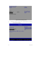
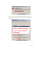
3 Select "Boot Manager" Menu ................................................................ 45
4 Select "EFI Internal Shell" from "Boot Manager" ...................................... 45
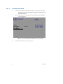
5 Select "Boot Maintenance Manager" from Front Page .............................. 46
6 Select "Boot From File" menu .............................................................. 47
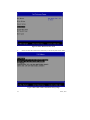
7 Select disk contains "EFI Shell" binary image .......................................... 47
8 Select Shell.efi binary image ................................................................ 48
9 EFI network driver layout..................................................................... 50
10 Debug/Info message output ...............................................................52
11 INT 3 is triggered.............................................................................. 53
12 Select System Debugger .................................................................... 53
13 Debugger is launched at first break point.............................................. 54
March, 2010
TABLES
Table
Table
Table
Table
Table
Table
Table
Table
Table
vi
1
2
3
4
5
6
7
8
9
Microsoft Visual Studio ......................................................................... 13
Intel C++ Compiler .............................................................................. 13
Microsoft Window Driver Development Kit (DDK) ...................................... 14
Software Needed by GCC Tool Chain....................................................... 14
ACPI Compiler ..................................................................................... 15
Microsoft Visual Studio.........................................................................15
Intel C++ Compiler for EFI Byte Code Compiler........................................ 16
The list of supported tool chain tags ....................................................... 21
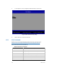
Internal shell commands ....................................................................... 48
March, 2010
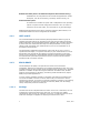
Revision History
Revision
Number
Description
Revision
Date
0.5
Initial document
09/11/2008
0.6
UnixPkg instruction, and Tools_def.txt updates, plus Run
network under NT32, DUET Unix build and set up, Option
ROM generation, and general editing and formatting
June 9, 2009
0.7
EdkII project website and repository update, plus new core
package introduction, new MDEPKG_NDEBUG build macro,
generic build error info
March 1, 2010
vii
March, 2010
viii
March, 2010
1
EDKII Introduction
This document provides detailed instructions for downloading, configuring and building
an EDKII project as well as running EDKII Emulation Environments.
1.1
Overview
This chapter describes the features introduced by EDKII project and elaborates the
role played by several key features. This chapter provides readers with a basic
understanding on EDKII after reading.
The features introduced by EDKII include:
Minimal unit of distribution.
EDKII introduces the concept of Packages. It is the basic unit of code
release. Compared to EDK, EDK II users can release and work with
"Packages", as opposed to the “Whole Source Tree”.
Different implementations for the same functionality.
EDKII introduces the concept of Library Class/Library Instance. Library
class is a set of standard interfaces for common support routines, and
library instance supplies the implementation of these interfaces. Platform
integrator can select different implementations upon various application
scenarios.
Uniform configuration interface for module writers.
Platform Configuration Database (PCD) is a mechanism that provides
module writers a uniform interface to extract external input information
determined in build time or run time of firmware. This mechanism
standardizes the exposure of platform and module settings that can inturn facilitate platform porting.
Cross-architecture and Cross-compiler ability.
EDKII source supports various architectures, such as IA32, X64, IA64, and
various tool-chains, such as Microsoft VC, GNU GCC and Intel ICC. To
support this capability, EDKII offers specific implementations for
architecture-related or compiler-related functions in libraries.
Binary compatibility for pre-PI modules.
The EDKII provides thunk drivers to address the binary compatibility
issues with using existing pre-PI EDK modules in a platform comprised of
mostly EDK II modules.
1
Refined basic APIs (known as Module Development Environment Library).
In EDKII there are many APIs that are refined and appended for module
developers, such as the PCI library, I/O library and Print library, etc.
Enhanced build system.
Its infrastructure is based on Python that is independent of the operating
system. It exposes several configuration files that a user can utilize to
choose the various tool-chains, even the build rule or generated target.
EDKII provides definitions and the library interface required by EDK modules, so it
makes EDK modules that can be integrated into the EDKII.
1.1.1
UEFI and PI
The Unified Extensible Firmware Interface (UEFI) Specification defines a group of
standard interfaces between the operating system (OS) and the platform firmware.
UEFI's predecessor was the Extensible Firmware Interface (EFI), originally developed
by Intel. Intel later contributed ownership of the EFI specification to a non-profit,
industry trade organization The Unified EFI Forum, who is now responsible for its
development and promotion.
The UEFI Platform Initialization Specification (also known as the “PI”) is a set of
specifications developed, in conjunction with UEFI, by The Unified EFI Forum. The PI
Specification was preceded by Intel Platform Innovation Framework for EFI (also
known as “the Framework”). While UEFI/EFI specifies the OS-to-firmware interface,
the PI/Framework specification specifies the structure used to build the firmware
beneath the OS-to-firmware interface.
1.1.2
EDK & EDKII
The EFI Developer Kit (EDK) is an Open Source release of the Framework
Foundations, defined in the Framework Core Interface Specifications (CIS), plus a set
of sample drivers and three sample targets implemented for the Nt32, Unix, and DUET
platforms. In addition to Open Sourcing the Framework Foundation code, the EDK
allows for the development, debugging, and testing of EFI and DXE drivers, Option
ROMs, and pre-Boot applications.
To solve customer feedback exposed by using EDK, Intel started a remodeling plan
now known as EDKII. It focuses on how to make it easy for customers to write a
specific kind of module, to port and to customize modules to a platform. The following
sections elaborate on several key concepts introduced by EDKII, such as Package,
Library Class/Library Instance and PCD, etc.
1.1.2.1
Package
The EDK could not be compiled without the entire source tree. Furthermore, the unit
of distribution required the EDK as the whole tree. To solve this issue, EDKII
introduced the new concept, the "Package". Using this, a release and its work can be
made with "Packages" as opposed to requiring the “Whole Source Tree”.
2
March, 2010
A package is the minimal unit of distribution—as well as providing a natural split in a
big project—which serves various purposes. For example, from the viewpoint of
hardware a developer may divide CPU/chipset/platform related definitions and drivers
into three individual packages that facilitate a user's distribution and reuse.
Developers also can put all modules that are independent of various platforms into a
single package. Therefore, developers only need focus on platform-specific code when
porting to a new platform.
The EDKII provides a set of packages, which are introduced in next chapter. As some
of the packages are not necessary for building a given module or firmware, Firmware
developers can only choose relevant packages to finish building or releasing.
Additionally, a developer can also create and distribute his or her own package based
on the EDKII code base. For further information, please refer to the EDKII Package
Specification.
1.1.2.2
Library class/Library Instance
Because demand exists for the same functionality in the development of firmware, but
different implementations may be needed, such as:
using C code to provide cross-architecture ability rather than using assembly
to provide better performance,
using I/O port to perform PCI configuration cycles but not using memory I/O
instructions.
The Library Class is a set of standard API definitions that are used to provide certain
functionality. A module writer can directly use them to program. A library instance
supplies the implementation of these APIs. The relationship between library class and
library instance is one-to-many. A library class may have multiple implementations,
that is, multiple library instances.
A module only depends on a library class and not concrete implementations, so the
same module source code can be easily configured to link with different library
instances for various requirements.
The EDKII provides many library classes/library instances to facilitate user
development in the MdePkg.
For example, MdePkg provides a library class named BaseMemoryLib, in which there
are many APIs related to memory operation. For this library class there are multiple
library instances, such as the following:
one implemented in C to cross platform,
one implemented in ASM to improve the efficiency of memory operation..
The platform integrator can selectively choose various library instances.
1.1.2.3
Platform Configuration Database
PCD is a unified mechanism used by a module to extract information from external
sources and control procedure behavior. The information can come from many
different places. Information could be known
3
at compile time,
March, 2010
at flash image generation time,
on the fly (when firmware code is being executed).
The module writer does not need to know where the information has come from
because the platform developer can make the selection. The module's source code can
remain unchanged to support multiple platforms, as all the external input information
is extracted by unified PCD interfaces.
For example, a PCD, "PcdDebugPrintErrorLevel", is used to control the debug print
level. Thus, a module developer only needs to call the PCD interface PcdGet32
(PcdDebugPrintErrorLevel) to extract its value. The value of the PCD is determined by
a platform configuration in the module build. Various values may cause different
behavior, such as enabling or disabling the display of particular debug print
statements.
1.2
Related Information
1.2.1
Useful publications and sources of information
Unified Extensible Firmware Interface Specification Version 2.1, The Unified EFI
Forum, Inc, 2007, http://www.uefi.org.
Extensible Firmware Interface Specification Version 1.10, Intel, 2001,
http://developer.intel.com/technology/efi.
Intel® Platform Innovation Framework for EFI Specifications, Intel, 2006,
http://www.intel.com/technology/framework/.
1.2.1.1
TianoCore.org site documentation
http://sourceforge.net/projects/edk2/files/
EDK II INF File Specification, Version 1.2, Intel, 2009.
EDK II DSC File Specification, Version 1.2, Intel, 2009.
EDK II DEC File Specification, Version 1.2, Intel, 2009.
EDK II FDF (Flash Description File) File Specification, Version 1,2, Intel, 2009.
EDK II Build Specification, Version 1.2, Intel, 2009.
1.3
Terms
The following terms are used throughout this document to describe varying aspects of
input localization:
4
March, 2010
EDK
EFI Developer’s kit, the open source project of the Intel Platform
Innovation Framework for EFI that can be found at
http://sourceforge.net/apps/mediawiki/tianocore/index.php?title=EDK .
EDK II
A generic term to describe the open source project found at
http://sourceforge.net/apps/mediawiki/tianocore/index.php?title=EDK2 .
In this document, it refer to the new release of EDK II which support build
infrastructure that makes use of the Extended INF, DEC and Extended
DSC.
EDK II Module
A generic term to describe a module that is developed using the new
release of EDK II project that supports the library class, library instances,
packaging concept and Extended INF, DEC and Extended DSC files.
EFI
Generic term that refers to one of the versions of the EFI specification: EFI
1.02, EFI 1.10, UEFI 2.1, UEFI 2.2 or UEFI 2.3.
Framework
Intel® Platform Innovation Framework for EFI consists of the Foundation,
and other modular components that characterize the portability surface for
modular components designed to work on any implementation of the
Tiano architecture.
Library Class
A library class defines the API or interface set for a library. The consumer
of the library is coded to the library class definition. Library classes are
defined via a library class .h file that is published by a package. See the
EDK 2.0 Module Development Environment Library Specification for a list
of libraries defined in this package.
Library Instance
An implementation of one or more library classes. See the EDK 2.0 Module
Development Environment Package Document at
http://sourceforge.net/projects/edk2/files/ for a list of library defined in
this package.
Module
A module is either an executable image or a library instance. For a list of
module types supported by this package, see module type.
5
March, 2010
Module Type
All libraries and components belong to one of the following module types:
BASE, SEC, PEI_CORE, PEIM, DXE_CORE, DXE_DRIVER,
DXE_RUNTIME_DRIVER, SMM_CORE, DXE_SMM_DRIVER,
DXE_SAL_DRIVER, UEFI_DRIVER, or UEFI_APPLICATION. These
definitions provide a framework that is consistent with a similar set of
requirements. A module that is of module type BASE, depends only on
headers and libraries provided in the MDE, while a module that is of
module type DXE_DRIVER depends on common DXE components.
Package
A package is a container in which a set of modules are organized together
in accordance with certain purpose or rule.
PCD
Platform Configuration Database.
PI
Platform Initialization Specification.
UEFI Application
An application that follows the UEFI specification. The only difference
between a UEFI application and a UEFI driver is that an application is
unloaded from memory when it exits regardless of return status, while a
driver that returns a successful return status is not unloaded when its
entry point exits.
UEFI Driver
A driver that follows the UEFI specification.
UEFI Specification Version 2.1, 2.2 and 2.3
A series of the UEFI specifications released by the Unified EFI Forum.
These specifications build on the EFI 1.10 specification and transfers
ownership of the EFI specification from Intel to a non-profit, industry trade
organization.
Unified EFI Forum
A non-profit collaborative trade organization formed to promote and
manage the UEFI standard. For more information, see www.uefi.org.
1.4
Target Audience
This document is intended to be a reference for those who are just starting EDKII
development, for the following:
• IBVs and OEMs who will implement UEFI/PI drivers or other firmware products
based on EDKII.
6
March, 2010
• IHVs who will be create supported firmware drivers for hardware device, as well as
platform integrators using EDKII components and modules.
7
March, 2010
8
March, 2010
2
Setting Up EDKII Development
Environment
This chapter explains how to download the EDKII source code, and introduces the
third-party software needed by the EDKII build process. This chapter also introduces
the basic structure of the EDKII source code and provides a quick start to build and
launch an NT32 emulation platform.
2.1
How to Get the EDKII Source
TianoCore.org
(http://sourceforge.net/apps/mediawiki/tianocore/index.php?title=Welcome_to_Tiano
Core ) is the website of the EFI and Framework Open Source Community, where
there are the documentation, source and binaries available. Users may also access the
Forums, Issue Tracking, Mailing Lists, RSS Feeds and Source Control on this website.
The Source Control is Subversion for all projects on this website, including EDKII
project.
There are systematic instructions at
(http://sourceforge.net/apps/mediawiki/tianocore/index.php?title=Step-bystep_instructions ), which help new developers set up their build environment and
build their first EDK II package. The instructions also cover setting up builds for Unixlike platforms, including building a GCC UEFI cross compiler for EDK II development.
The EDKII source repository is
https://edk2.svn.sourceforge.net/svnroot/edk2/trunk/edk2/.
Before downloading EDKII source, obtain an account on http://www.sourceforge.net.
Please register it at https://sourceforge.net/account/registration/.
2.2
EDKII Packages
EDKII source consists of several packages, shown in the following directories of the
download directory.
BaseTools
Provides the binary build tools and the templates of configuration files for
building. Build tools belong to another project, please visit
http://sourceforge.net/apps/mediawiki/tianocore/index.php?title=Edk2buildtools to get the source codes of build tools.
9
Conf
Only has one readme.txt file. This directory will be used to contain the
configuration files of building target and compiler parameters used for
building.
MdePkg
Declares PROTOCOLs, PPIs, GUIDs and related data structures defined in
UEFI, EFI, and PI Specifications (http://www.uefi.org) and industry
standards. In addition, this package encompasses library instances
defined in Module Development Environment, which provides services for
all the execution phases in the Intel Platform Innovation Framework for
EFI.
MdeModulePkg
Provides a group of modules crossing platforms, based on UEFI, EFI, and
PI Specifications. It also includes the libraries instances serviced for these
modules.
IntelFrameworkPkg
Declares PROTOCOLs, PPIs, GUIDs and related data structures are defined
in Intel Platform Innovation Framework Specification for EFI
(http://developer.intel.com/technology/framework/spec.htm). In addition,
this package encompasses library instances based on Intel Platform
Innovation Framework Specification.
IntelFrameworkModulePkg
Provides a group of libraries instances and modules crossing platforms,
based on Intel Platform Innovation Framework Specification. It also
includes the libraries instances serviced for these modules.
EdkShellPkg
Provides the build instructions of Shell project. EFI Shell belongs to
another project, please visit
http://sourceforge.net/apps/mediawiki/tianocore/index.php?title=Efi-shell
for more details.
EdkShellBinPkg
Provides the binary Shell files and the binary shell applications for
different CPUs architectures.
EdkFatBinPkg
Provides the binary FAT drivers for different CPUs architectures. FAT driver
belongs to another project, please visit
http://sourceforge.net/apps/mediawiki/tianocore/index.php?title=Edk2fatdriver2 to get the source code of FAT driver.
10
March, 2010
Nt32Pkg
Launched at 32-bit Microsoft Window operating system and provides a
UEFI runtime environment.
UnixPkg
Launched in general 32-bit Unix-like operating system, such as a UNIX or
Linux distributions.
DuetPkg
Provides UEFI runtime environment based on legacy BIOS on the real
machine.
OptionRomPkg
Shows the sample drivers to build PCI compliant Option ROMimage for
different CPUs architectures.
EdkCompatibilityPkg(ECP)
Includes EDK style definitions of EFI1.10, EFI2.0 and all definitions of Intel
Framework Specification and the EDK libraries instances to allow EDK style
modules to be used in EDKII context. It also has some thunk drivers that
provide transition between the different protocols defined in UEFI2.1/PI1.0
specifications and the Intel Platform Innovation Framework Specification.
The primary goal of the ECP is to enable build compatibility of EDK
modules in the EDKII and to address the binary compatibility issues with
using existing pre-PI EDK modules in a platform comprised of mostly
EDKII modules.
PcAtChipsetPkg
Designed to public interfaces and implementation that follows PcAt de
facto standard.
UefiCpuPkg
Provides UEFI compatible CPU modules and libraries.
OvmfPkg
Aims to support firmware for Virtual Machines using the edk2 code base.
More information can be found at:
http://sourceforge.net/apps/mediawiki/tianocore/index.php?title=OVMF .
Each package has the similar structure of directories. For example, MdePkg has the
following directories and sub-directories:
Include\
11
-- public header files of MDE Package
Ia32\
-- internal header files specified to IA-32 architecture
X64\
-- internal header files specified to x64 architecture
Ipf\
-- internal header files specified to IPF architecture
March, 2010
Ebc\
Uefi\
Pi\
Protocol\
Ppi\
Guid\
-- internal header files specified to EBC architecture
-- public header files containing UEFI2.1 definitions
-- public header files containing PI1.0 definitions
-- public header files containing PROTOCOLs definitions
-- public header files containing PPIs definitions
-- public header files containing GUIDs definitions
IndustryStandard\
-- public header files containing Industry Standard
Library\
Library\
-- public header files containing MDE Libraries classes
-- MDE libraries instances
The internal header files only could be referred by those public header files.
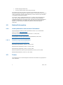
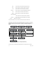
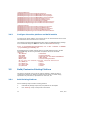
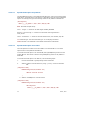
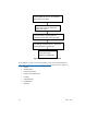
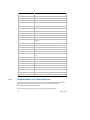
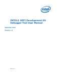
A dependency relationship exists among EDKII packages. For example, the module in
MdeModulePkg uses the protocols defined in MdePkg, so MdeModulePkg will depend on
MdePkg. The following chart illustrates the dependencies among the packages in
EDKII.
Figure 1 Packages Dependency
From this chart, the following basic dependencies can be discovered, for example:
12
March, 2010
2.3
1.
To build OptionRomPkg, only MdePkg and BaseTools are required.
2.
To build EdkCompatibilityPkg, only MdePkg, IntelFrameworkPkg and BaseTools
are required.
3.
To build EdkShellPkg, only EdkCompatibilityPkg and BaseTools are required.
4.
To build the NT32/Unix/Duet emulation platforms, MdePkg, MdeModulePkg,
IntelFrameworkPkg, IntelFrameworkModulePkg, EdkFatBinPkg,
EdkShellBinPkg and BaseTools are required.
Third-Party Tools
Besides downloading EDKII source, some third-party tools are still needed to build
EDKII. The third-party tools include a C compiler and an assembler. An ACPI compiler
is required to build ACPI table.
2.3.1
Target for IA-32 and Intel64 Processors
To build EDKII for the platforms based on IA-32 or Intel64 processors, the following
compiler tool chains may be selected.
1.
Microsoft Visual Studio
One version of Microsoft Visual Studio from Table 1 may be installed to build
EDKII.
Table 1 Microsoft Visual Studio
Name
Version
URL
Microsoft Visual
Studio
2005
Professional
http://msdn2.microsoft.com/en-us/vstudio
Microsoft Visual
Studio
2003 .NET
http://msdn2.microsoft.com/en-us/vstudio
By default, the EDKII source on
http://sourceforge.net/apps/mediawiki/tianocore/index.php?title=Edk2
is set to use Microsoft Visual Studio 2005 Professional to build the IA-32 and
Intel64 processors-based platforms.
2.
Intel C++ Compiler (ICC)
Table 2 Intel C++ Compiler
Name
Intel C++ Compiler for
Windows
Version
9.1
URL
http://www.intel.com/support/performancetools/c/wi
ndows/index.htm
After the downloading web page, select the correct version number to
download.
13
March, 2010
Build EDKII using an Intel C++ Complier requires a Microsoft Visual Studio
installation. Please refer to Table 1 to install one version of Microsoft Visual
Studio.
3.
Microsoft Windows Driver Development Kit (DDK)
To build a physical platform (because it has 16-bit assembly codes) the
Microsoft Windows Driver Development Kit must be installed. Please refer to
Table 3 to install it.
Table 3 Microsoft Window Driver Development Kit (DDK)
Name
Microsoft Windows
Driver Development
Kit (DDK)
4.
Version
2790.1830
URL
http://download.microsoft.com/download/9/0/f/90f0
19ac-8243-48d3-91cf81fc4093ecfd/1830_usa_ddk.iso
GCC Tool Chain
There are two GCC tool chains. One is used to build and launch Unix
Emulation Platform on platforms based on the IA-32 processor. Another is
used to build UEFI images running on the actual platforms.
To build and launch Unix Emulation Platform target, requirements include the
32-bit Unix-like operating system environments and a group of software that
includes GNU C Compiler, GNU Binutils, GNU Glib C, X11, SQlite and Python.
The software provided by a Unix-like operating system can be used directly, or
downloaded and built as listed in Table 4.
Table 4 Software Needed by GCC Tool Chain
Name
GNU C Compiler (GCC)
Version
URL
4.2.1
http://gcc.gnu.org/gcc-4.2/
GNU Binutils
2.17.50
http://ftp.gnu.org/gnu/binutils/
GNU Glib C
2.3.6
http://ftp.gnu.org/gnu/glibc/
X11
7.2
http://ftp.x.org/pub/X11R7.2/
SQLite
3.0 or later
http://www.sqlite.org
Python
2.5.2 or later
http://www.python.org/
To build EDKII as a target for IA32 and Intel64 architectures, the updated
software to generate the UEFI images capable of running on actual platforms
will be needed. First, the SQLite and Python version listed in the upper table
will need to be downloaded and installed. Then use the script
http://edk2.svn.sourceforge.net/svnroot/edk2/trunk/edk2/BaseTools/gcc/min
gw-gcc-build.py to download all needed software and to build automatically.
This script belongs to BaseTools project. Use your account on
http://sourceforge.net/apps/mediawiki/tianocore/index.php?title=Welcome_to
_TianoCore to download it.
14
March, 2010
5.
ACPI Compiler
To build ACPI tables, one of ACPI compilers listed below needs to be installed.
Table 5 ACPI Compiler
Name
2.3.2
Version
URL
ACPI Component
Architecture
20061109
or later
http://acpica.org/downloads/
Microsoft ACPI
Source Language
(ASL) Assembler
3.0.0NT or
later
http://www.microsoft.com/whdc/system/pnppwr/powe
rmgmt/default.mspx
Target for Intel Itanium Family Processors (IPF)
To build EDKII for the platforms based on Itanium Processor Family (IPF) processors,
the following compiler tool chains may be selected.
1.
Microsoft Visual Studio
Table 6 Microsoft Visual Studio
Name
Microsoft Visual
Studio
Version
2005 Team Suite
URL
http://msdn2.microsoft.com/en-us/vstudio
When installing Microsoft Visual Studio 2005 Team Suite, IA64 support must
be selected.
2.
Intel C++ Compiler (ICC)
Please refer to Table 2 to install the Intel C++ Compiler. To build EDKII with
Intel C++ Complier, a Microsoft Visual Studio installation is also required.
Please refer to Table 1 to install one version of Microsoft Visual Studio.
3.
Microsoft Windows Driver Development Kit (DDK)
By default, the EDKII source on
http://sourceforge.net/apps/mediawiki/tianocore/index.php?title=Welcome_to
_TianoCore is set to use Microsoft Windows Driver Development Kit (DDK) to
build the Intel Itanium Processor Family processors-based platforms. Please
refer to Table 3 to install Microsoft Windows Driver Development Kit (DDK).
4.
ACPI Compiler
To build ACPI tables, one of ACPI compilers listed in Table 5 must be installed.
2.3.3
Target for EFI Byte Code (EBC) Image
The Intel C Compiler for EFI Byte Code creates EFI Byte Code (EBC) images that can
be executed by systems implementing the EFI 1.10, UEFI 2.0, or later specifications.
15
March, 2010
These systems include an EBC interpreter that loads and interprets the EBC image,
allowing the image to be executed on multiple platforms and architectures, including
those based on Intel Itanium processors, IA-32 architecture-based processors, or
Intel64 architecture-based processors.
Table 7 Intel C++ Compiler for EFI Byte Code Compiler
Name
Intel C++
Compiler for EFI
Byte Code
Version
1.2
URL
http://www3.intel.com/cd/software/products/asmona/eng/compilers/efibc/index.htm
To build EBC image, the Intel C Compiler for EFI Byte Code and Microsoft Visual
Studio must be installed. Refer to Table 1 for installation of Microsoft Visual Studio.
2.4
A Quick Build
The following instructions will build and launch an NT32 emulation platform
systematically.
1.
Enter EDKII root directory
Run edksetup.bat --nt32
2.
Run build
3.
Execute build run
16
March, 2010
3
EDKII Build Process
3.1
Basic build steps introduction
Chapter 2 explained how to build an NT32 platform. In this chapter, the basic build
steps are introduced in detail.
Step 1:
Download EDKII project as the basic workspace, and install the required tool chain. If
necessary, other modules and packages can also be added into this workspace. This
step is shown in Chapter 2.
Step 2:
In the workspace (EDKII root directory), run edksetup script to set up the build
environment. For an Nt32 platform, the --nt32 option is required to setup the
“standard” places for include (.h) and dll files required by the Nt32 platform.
Step 3:
Configure the active platform, such as build options, target, build tool chain and build
rules. The build configuration is introduced in section 3.2.
Step 4:
Call build command to build the platform, module or target configured in step 3. See
section 3.2.2 regarding the build command option. See section 3.5 regarding the
platform build and customization. The module build is introduced in section 3.4. The
build targets are listed in the end of this section.
Step 5:
Post build steps can be done according to custom requirements. For an NT32
platform, execute the build run command to run NT32 emulation. For the option
ROM image, create the option ROM.
The above run is a build target for build command to start NT32 emulation. Besides,
there are other useful build targets. They are:
build
build all
Build all libraries, component PE/COFF images and FV/FD images.
17
build clean
March, 2010
Clean the intermediate output files (such as the compiled obj files) except the
generated Makefile files (top level and module makefiles) and AutoGen files.
build cleanall
Clean all generated files and directories during build.
build fds
Only generate FV and FD image.
3.2
Build Configuration
Build configuration includes three aspects. They are separate for the active platform,
the tool chain and build rule. The build configuration information is stored in three txt
files: target.txt, tools_def.txt and build_rule.txt. Their template that contains the
default setting provided by EDKII is created in the $(WORKSPACE)/Conf directory after
build Step 2. The following sections introduce each txt file.
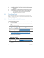
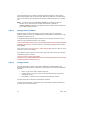
3.2.1
Configure the active platform
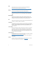
The active platform is the built target. It can be set in the target.txt file or in build
command line options. Target.txt is used to filter the build so that everything is not
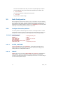
always built. It contains a group of build settings listed in the following example.
Example: Conf/target.txt
ACTIVE_PLATFORM
TARGET
TARGET_ARCH
TOOL_CHAIN_CONF
TOOL_CHAIN_TAG
MULTIPLE_THREAD
MAX_CONCURRENT_THREAD_NUMBER
BUILD_RULE_CONF
3.2.1.1
=
=
=
=
=
=
=
=
Nt32Pkg/Nt32Pkg.dsc
DEBUG
IA32
Conf/tools_def.txt
MYTOOLS
Enable
2
Conf/build_rule.txt
ACTIVE_PLATFORM
ACTIVE_PLATFORM specifies the $(WORKSPACE) relative path and filename of the
platform description file (DSC) that will be used for the build. The setting for the
example above is the Nt32 platform DSC file.
3.2.1.2
TARGET
TARGET refers to zero or more of DEBUG, RELEASE, or UserDefined; separated by a
space character. If the line is missing or no value is specified, all valid targets
specified in the platform description file will attempt to be built. The current setting is
to build the debug platform target.
18
March, 2010
3.2.1.3
TARGET_ARCH
TARGET_ARCH specifies what kind of architecture is for which binary targeted. One or
more of IA32, IPF, X64, or EBC can be set. Multiple values can be specified on a
single line by using space character to separate them.
If the platform requires multiple architectures, for example 32bit Pei module and 64bit
Dxe module, this option must be set to IA32 X64.
If the module is built for multiple architectures, for example a library is built for IA32
and X64, this option must also be set to IA32 X64.
If the line is missing or no value is specified, all supported architectures specified in
the platform description file will attempt to be built.
The current setting is to build IA32 platform.
3.2.1.4
TOOL_CHAIN_TAG
TOOL_CHAIN_TAG specifies the tool TagName defined in tools_def.txt to be used for
build. By default, MYTOOLS TagName is chosen. It refers to Microsoft Visual Studio
2005 for IA32 and X64 target architecture, and the Microsoft Windows DDK (WINDDK)
version 3790.1830 for IPF target architecture.
3.2.1.5
MULTIPLE_THREAD and MAX_CONCURRENT_THREAD_NUMBER
MULTIPLE_THREAD and MAX_CONCURRENT_THREAD_NUMBER are used to enable multithread build. We recommend setting the number of concurrent threads to one more
than the number of computer cores or CPUs in the machine used. This feature is only
available for "spawn" build mode, such as platform build. However, the clean, cleanall
or stand-alone module build continue to use the normal method.
3.2.1.6
TOOL_CHAIN_CONF and BUILD_RULE_CONF
TOOL_CHAIN_CONF and BUILD_RULE_CONF specify the name of the files, which specify
the tool chains and build rules to be used for build. By default, tools_def.txt and
build_rule.txt are used.
3.2.2
Build command options
Build command provides the command line options to configure the build process,
which can override the build configurations in target.txt. If the corresponding build
option is not set, the build setting is from target.txt. Otherwise, the build setting is
decided by build command line options. Some usual usages of Build command are
followed.
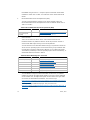
3.2.2.1
Set the build configuration (Target, Arch, and Tool chain)
build -a X64 -t MYTOOLS -b DEBUG
19
March, 2010
The active platform defined in target.txt file will be built to the debug images for X64
arch under MYTOOLS tool chain. The active platform is not overridden.
-a option sets the build arch to override TARGET_ARCH setting in target.txt.
-t option sets the tool chain to override TOOL_CHAIN_TAG setting in target.txt.
-b option sets the build target to override TARGET setting in target.txt.
3.2.2.2
Set the active platform
build -p MyPlatform\MyPlatformPkg.dsc
MyPlatform is built as the active platform.
-p option sets the active platform to override ACTIVE_PLATFORM setting in target.txt.
3.2.2.3
Build a specified module
build -m MdeModulePkg\Application\HelloWorld\HelloWorld.inf
The “HelloWorld” application is built as the single module based on the active platform
specified in target.txt. This application INF file must be specified in the active platform
DSC file.
-m option sets the INF file name of the module to be built. This setting is not
supported in target.txt.
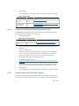
3.2.2.4
Build a specified FV/FD image
build -p Nt32Pkg/Nt32Pkg.dsc -i FvRecovery -r Nt32
The FvRecovery FvImage and Nt32 FD image will be created for NT32
platform.
-r option sets the name of FD image to be generated. The name must be from [FD]
section in FDF file.
-i option sets the name of FV image to be generated. The name must be from [FV]
section in FDF file.
The full build command usage can be obtained by build --help and
Build_Utility_Man_Page located at
http://edk2.svn.sourceforge.net/svnroot/edk2/trunk/edk2/BaseTools/UserManuals.
3.2.3
Configure the build tool chain and flags
The third party tools and tool flags are described in tools_def.txt file. The template
tools_def.txt file defines the following tool chain tags commonly used in EDKII:
20
March, 2010
Table 8 The list of supported tool chain tags
Tool Chain Tags
3.2.3.1
Description
VS2003
win32 - Microsoft Visual Studio .NET 2003, Intel EBC, Intel ASL
VS2005
win32 - Microsoft Visual Studio 2005 Team Suite Edition, Intel EBC,
Intel ASL (also compatible with VS 2005 Express, Standard, and Pro)
DDK3790
win32 - Microsoft Windows DDK 3790.1830, Intel EBC, Intel ASL
UINIXGCC
Mingwin GCC, No EBC, Intel ASL
ELFGCC
Linux ELF GCC, No EBC, Intel ASL
CYGGCC
win32 - CygWin GCC, Intel EBC, Intel ASL
ICC
win32 - Intel C Compiler V9.1, Intel EBC, Intel ASL
MYTOOLS
win32 - VS2005 for IA32/X64, WINDDK 3790.1830 for IPF, Intel
EBC, Intel ASL
VS2003xASL
win32 - Microsoft Visual Studio .NET 2003, Intel EBC, Microsoft ASL
VS2005xASL
win32 - Microsoft Visual Studio 2005 Team Suite Edition, Intel EBC,
Microsoft ASL
DDK3790xASL
win32 - Microsoft Windows DDK 3790.1830, Intel EBC, Microsoft ASL
CYGGCCxASL
win32 - CygWin GCC, Intel EBC, Microsoft ASL
ICCxASL
win32 - Intel C Compiler V9.1, Intel EBC, Microsoft ASL
VS2005x86
win64 - Microsoft Visual Studio 2005 Team Suite Edition (x86), Intel
EBC, Intel ASL (also compatible with VS 2005 Express, Standard, and
Pro)
ICCx86
win64 - Intel C Compiler V9.1 (x86), Intel EBC, Intel ASL
VS2005x86xASL
win64 - Microsoft Visual Studio 2005 Team Suite Edition (x86), Intel
EBC, Microsoft ASL (also compatible with VS 2005 Express, Standard,
and Pro)
ICCx86xASL
win64 - Intel C Compiler V9.1 (x86), Intel EBC, Microsoft ASL
CYGGCCx86
win64 - CygWin GCC (x86), Intel EBC (x86), Intel ASL
CYGGCCx86xASL
win64 - CygWin GCC (x86), Intel EBC (x86), Microsoft ASL
Change tool chain location
When the tool chain location is different from the default setting in tools_def.txt, users
can change the tool path definition to point to their tool chain location. For example, if
the VS2003 installation directory is D:\Program Files\Microsoft Visual Studio
.NET 2003, these two path macros need to be changed as follows:
DEFINE VS2003_BIN = D:\Program Files\Microsoft Visual Studio .NET
2003\Vc7\bin
DEFINE VS2003_DLL = D:\Program Files\Microsoft Visual Studio .NET
2003\Common7\IDE
21
March, 2010
3.2.3.2
Change tool flags
When the default tool flags do not meet requirements, update them in tools_def.txt.
For example, to disable all compiler optimization for VS2003 tool chain, the VS2003 CC
FLAGS needs to use /Od option in place of /O1 option like:
DEBUG_VS2003_IA32_CC_FLAGS = /nologo /c /WX /W4 /Gs8192 /Gy /D UNICODE
/Od /GL /FIAutoGen.h /EHs-c- /GR- /GF /GX- /Zi /Gm
3.2.3.3
Add new tool chain
For tool chains other than the tool chain list (given above) defined in tools_def.txt,
add it into tools_def.txt file. Similar to the existing tool chain definition, such as
VS2003, users can quickly define the new TagName to contain their tool chain and tool
flags.
For more detail information, refer to the template tools_def.txt file and EDK II Build
Specification Chapter 5.
3.2.4
Configure the build rules
The build rules describes how the individual source files are compiled and linked.
These rules are defined in build_rule.txt file. The template build_rule.txt file provides
the common build rules to cover all source files in EDKII, such as *.c, *.h, *.asm
files and so on. However, if a new type file is added to be built, the corresponding
build rule for this file must be created into build_rule.txt. The instructions on how to
create build rule can be referred to in the EDK II Build Specification Chapter 5.
3.3
Build Output Directory
When the platform is built successfully, all build output files are generated into the
directory:
$(WORKSPACE)/$(OUTPUT_DIRECTORY)/$(TARGET)_$(TOOL_CHAIN_TAG)
WORKSAPCE is the EDKII root directory.
OUTPUT_DIRECTORY is from the platform DSC file [Defines] section. For the
platforms provided by EDKII, this value is always set to Build/PlatformName
so that all output files are in the same build directory.
TARGET, TOOL_CHAIN_TAG and ARCH are determined by settings in target.txt
or the build command line options.
The EFI images (*.efi) and EFI OptionRom images (*.rom) are created in $(ARCH)
subdirectory:
$(WORKSPACE)/$(OUTPUT_DIRECTORY)/$(TARGET)_$(TOOL_CHAIN_TAG)/$(ARCH)
The FV (*.fv) and FD (*.fd) images are created in FV subdirectory:
22
March, 2010
$(WORKSPACE)/$(OUTPUT_DIRECTORY)/$(TARGET)_$(TOOL_CHAIN_TAG)/FV
Autogen.c/h is created in the DEBUG subdirectory of the module output directory:
$(WORKSPACE)/$(OUTPUT_DIRECTORY)/$(TARGET)_$(TOOL_CHAIN_TAG)/$(ARCH)/$(MO
DULE INF RELATIVE PATH to WORKSPACE)/$(MODULE INF NAME)/DEBUG
Intermediate output files, such as *.obj, are created in the module OUTPUT
subdirectory of the module output directory:
$(WORKSPACE)/$(OUTPUT_DIRECTORY)/$(TARGET)_$(TOOL_CHAIN_TAG)/$(ARCH)/$(MO
DULE INF RELATIVE PATH to WORKSPACE)/$(MODULE INF NAME)/DEBUG
For an Nt32 platform, its OUTPUT_DIRECTORY is set to Build/NT32 in NT32.dsc. The
build configuration is as follows: TARGET is DEBUG; TOOL_CHAIN_TAG is MYTOOLS;
ARCH is IA32.
The components of an EFI image are in:
$(WORKSPACE)/Build/Nt32/DEBUG_MYTOOLS/IA32
The FV and FD images are in:
$(WORKSPACE)/Build/Nt32/DEBUG_MYTOOLS/FV
The output directory for the Helloworld application of
MdeModulePkg/Application/HelloWorld/HelloWorld.inf is:
$(WORKSPACE)/Build/Nt32/DEBUG_MYTOOLS/IA32/MdeModulePkg/Application/Hello
World/HelloWorld/OUTPUT
Autogen.c and Autogen.h for a Helloworld application are in:
$(WORKSPACE)/Build/Nt32/DEBUG_MYTOOLS/IA32/MdeModulePkg/Application/Hello
World/HelloWorld/DEBUG
3.4
Build Single Module
In general, the single module (such as UEFI application and Option ROM ) can be built
by the following steps:
1.
Create a new package to contain this module. (Skip if the package exists)
2.
Add this module into a package. (Skip if the module is in a package)
3.
Run the edksetup script to set up the build environment.
4.
Configure the active platform to the package platform.
5.
Call the build command with -m option to build this module.
23
March, 2010
3.4.1
Create new Package
This step is only needed for a module that is not in any package. Creating the package
also creates two package metadata files: DEC and DSC.
The package declaration (DEC) file is used to define the package public information,
such as the header files, Library Class, Ppi, Protocol, Guid and PCD. The following
example is a dummy DEC file without any public information, and only defines the
package name and guid.
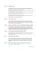
Example: Package.dec
[Defines]
DEC_SPECIFICATION
PACKAGE_NAME
PACKAGE_GUID
PACKAGE_VERSION
=
=
=
=
0x00010005
PackageName
xxxxxxxx-xxxx-xxxx-xxxx-xxxxxxxxxxxx
0.1
[Includes]
#include header file path, relative to package directory
[LibraryClasses]
#libraryclassname|librarclass header file name, relative to workspace
[Guids]
#GuidCName = {xxxxxxxx,xxxx,xxxx,{xx,xx,xx,xx,xx,xx,xx,xx}},
[Ppis]
#PpiGuidCName = {xxxxxxxx,xxxx,xxxx,{xx,xx,xx,xx,xx,xx,xx,xx}},
[Protocols]
#ProtocolGuidCName = {xxxxxxxx,xxxx,xxxx,{xx,xx,xx,xx,xx,xx,xx,xx}},
[PcdsFeatureFlag]
#PcdTokenSpaceCGuidName.PcdName|TRUE or FLASE|BOOLEAN|TokenNumber
[PcdsFixedAtBuild]
#PcdTokenSpaceCGuidName.PcdName|Value|DataType|TokenNumber
[PcdsPatchableInModule]
#PcdTokenSpaceCGuidName.PcdName|Value|DataType|TokenNumber
[PcdsDynamic]
#PcdTokenSpaceCGuidName.PcdName|Value|DataType|TokenNumber
[PcdsDynamicEx]
#PcdTokenSpaceCGuidName.PcdName|Value|DataType|TokenNumber
If necessary, the module in this package can publish the information in this file. For
details refer to EDKII DEC Specification.
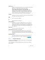
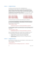
The platform build description (DSC) file includes the modules to be built, and their
dependent library instances and PCD values. The following example is from the EDKII
OptionRom DSC file. This DSC is created in order to build two option ROM drivers.
24
March, 2010
Example: OptionRomPkg.dsc
[Defines]
PLATFORM_NAME
= OptionRomPkg
PLATFORM_GUID
= C7B25F37-B1F4-4c46-99CB-3EA7DCF5FCDC
PLATFORM_VERSION
= 0.1
DSC_SPECIFICATION
= 0x00010005
OUTPUT_DIRECTORY
= Build/OptionRomPkg
SUPPORTED_ARCHITECTURES = IA32|IPF|X64|EBC
BUILD_TARGETS
= DEBUG|RELEASE
SKUID_IDENTIFIER
= DEFAULT
[SkuIds]
0|DEFAULT #The entry: 0|DEFAULT is reserved and required.
[LibraryClasses]
DebugLib | MdePkg/Library/UefiDebugLibStdErr/UefiDebugLibStdErr.inf
BaseLib | MdePkg/Library/BaseLib/BaseLib.inf
BaseMemoryLib | MdePkg/Library/BaseMemoryLib/BaseMemoryLib.inf
……
[PcdsFeatureFlag]
gEfiMdePkgTokenSpaceGuid.PcdComponentNameDisable|FALSE
gEfiMdePkgTokenSpaceGuid.PcdDriverDiagnosticsDisable|FALSE
gEfiMdePkgTokenSpaceGuid.PcdComponentName2Disable|FALSE
gEfiMdePkgTokenSpaceGuid.PcdDriverDiagnostics2Disable|FALSE
……
[PcdsFixedAtBuild]
gEfiMdePkgTokenSpaceGuid.PcdMaximumUnicodeStringLength|0x0
gEfiMdePkgTokenSpaceGuid.PcdMaximumAsciiStringLength|0x0
gEfiMdePkgTokenSpaceGuid.PcdMaximumLinkedListLength|0x0
……
[Components]
OptionRomPkg/AtapiPassThruDxe/AtapiPassThruDxe.inf
OptionRomPkg/CirrusLogic5430Dxe/CirrusLogic5430Dxe.inf
3.4.1.1
[Defines] section
The DSC name and guid are declared here. OUTPUT_DIRECTORY specifies the platform
output directory referred to in section 3.3. SUPPORTED_ARCHITECTURES lists the
supported ARCHs. BUILD_TARGETS defines the supported target.
3.4.1.2
[LibraryClasses] section
This section includes all library instances required by the modules in [Components]
section. The library instance is specified as follows:
LibraryClassName | Library Instance INF file relative to workspace.
3.4.1.3
[Pcds*] section
These sections set the values for the different type PCD used by the module. If the
value of the used PCD is not set in the DSC file, the PCD value will be the default
value in the package DEC file that publishes this PCD.
25
March, 2010
3.4.1.4
[Components] section
The modules to be built are specified here.
3.4.2
Add the module into a package
The module should be grouped into a package. It can be placed into the package
directory according to the package layout. For the recommended package layout, refer
to section 2.2.
To build the module, its INF file must be specified into the [Components] section of a
DSC file, and its dependent library instances and PCD values also need to be set in the
corresponding section of the DSC file.
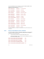
The module INF file includes the source files, the used Ppi, Protocol, Guid CName, the
dependent library classes and PCD. The following example is from MdeModulePkg
Application HelloWorld INF file. It does not depend on any Ppi, Protocol or Guid, but it
uses five library classes and two PCDs.
26
March, 2010
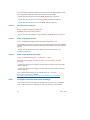
Example HelloWorld.inf
[Defines]
INF_VERSION
BASE_NAME
FILE_GUID
MODULE_TYPE
VERSION_STRING
ENTRY_POINT
= 0x00010005
= HelloWorld
= 6987936E-ED34-44db-AE97-1FA5E4ED2116
= UEFI_APPLICATION
= 1.0
= UefiMain
[Sources]
HelloWorld.c
[Packages]
MdePkg/MdePkg.dec
[LibraryClasses]
UefiBootServicesTableLib
UefiApplicationEntryPoint
UefiLib
DebugLib
PcdLib
[Guids]
[Ppis]
[Protocols]
[FeaturePcd]
gEfiMdeModulePkgTokenSpaceGuid.PcdHelloWorldPrintEnable
[Pcd]
gEfiMdeModulePkgTokenSpaceGuid.PcdHelloWorldPrintString
gEfiMdeModulePkgTokenSpaceGuid.PcdHelloWorldPrintTimes
3.4.2.1
[LibraryClasses] section
The names of library classes required by the module are listed here. HelloWorld is an
example to explain how to get all required library instances by the module. From the
above HelloWorld INF file, we know that HelloWorld directly depends on UefiLib,
DebugLib, UefiApplicationEntryPoint, UefiBootServicesTableLib and PcdLib
library classes. For these library classes, there are multiple library instances provided
in MdePkg. The following five instances are chosen for this application:
UefiApplicationEntryPoint|MdePkg/Library/UefiApplicationEntryPoint/UefiAp
plicationEntryPoint.inf
UefiBootServicesTableLib|MdePkg/Library/UefiBootServicesTableLib/UefiBoot
ServicesTableLib.inf
UefiLib|MdePkg/Library/UefiLib/UefiLib.inf
DebugLib|MdePkg/Library/UefiDebugLibStdErr/UefiDebugLibStdErr.inf
PcdLib|MdePkg/Library/DxePcdLib/DxePcdLib.inf
Of the five instances shown above, the UefiLib library instance requires more library
classes: PrintLib, BaseLib, BaseMemoryLib and MemoryAllocationLib. Another
four library instances are chosen:
27
March, 2010
PrintLib|MdePkg/Library/BasePrintLib/BasePrintLib.inf
MemoryAllocationLib|MdePkg/Library/DxeMemoryAllocationLib/DxeMemoryAlloca
tionLib.inf
BaseMemoryLib|MdePkg/Library/BaseMemoryLib/BaseMemoryLib.inf
BaseLib|MdePkg/Library/BaseLib/BaseLib.inf
Finally, BaseLib depends on the extra TimeLib. The time library NULL instance is
added.
TimerLib|MdePkg/Library/BaseTimerLibNullTemplate/BaseTimerLibNullTemplate
.inf
To build HelloWorld module, there are the ten library instances that must be specified
in the [LibraryClasses] section in the DSC file.
3.4.2.2
[Pcd*] section
The different types of PCDs used by the module are specified into the PCD type
sections, such as [FeaturePcd], [FixedPcd] sections. However, if the PCD type is not
limited, it should be in [Pcd] section and its PCD type is decided according to the
setting in DSC file. This application uses a feature flag PCD of
PcdHelloWorldPrintEnable and two common type PCDs of
PcdHelloWorldPrintString and PcdHelloWorldPrintTimes.
Next, get all required library instances and PCDs and add them into DSC file.
HelloWorld is also an example for explaining their dependencies.
In last section, all required library instances are chosen, and the PCD used by them is
decided. The following PCDs are used. Of PCDs, PcdHelloWorldPrintEnable,
PcdHelloWorldPrintString and PcdHelloWorldPrintTimes are directly used by
HelloWorld. Other PCDs are from these chosen library instances.
Although the used PCDs seem numerous, most of them can directly use their default
value defined in package DEC file. For users not wanting to use the default value, the
new value can be set in the [PCD] section of DSC file to override the default setting.
28
March, 2010
[PcdsFixedAtBuild]
gEfiMdePkgTokenSpaceGuid.PcdSpinLockTimeout
gEfiMdePkgTokenSpaceGuid.PcdMaximumLinkedListLength
gEfiMdePkgTokenSpaceGuid.PcdMaximumAsciiStringLength
gEfiMdePkgTokenSpaceGuid.PcdMaximumUnicodeStringLength
gEfiMdePkgTokenSpaceGuid.PcdDebugPrintErrorLevel
gEfiMdePkgTokenSpaceGuid.PcdDebugClearMemoryValue
gEfiMdePkgTokenSpaceGuid.PcdDebugPropertyMask
gEfiMdeModulePkgTokenSpaceGuid.PcdHelloWorldPrintString
gEfiMdeModulePkgTokenSpaceGuid.PcdHelloWorldPrintTimes
[PcdsFeatureFlag]
gEfiMdePkgTokenSpaceGuid.PcdDriverDiagnosticsDisable
gEfiMdePkgTokenSpaceGuid.PcdComponentNameDisable
gEfiMdePkgTokenSpaceGuid.PcdDriverDiagnostics2Disable
gEfiMdePkgTokenSpaceGuid.PcdComponentName2Disable
gEfiMdeModulePkgTokenSpaceGuid.PcdHelloWorldPrintEnable
3.4.3
Configure the active platform and build module
To configure the active platform, the target.txt file or the build command can be used.
The instructions refer to sections 3.2.1 and 3.2.2.
The following example builds AtapiPassThruDxe module in EDKII OptionRom package
to the release EFI images for EBC arch under the default MYTOOLS tool tag.
build -m OptionRomPkg/AtapiPassThruDxe/.inf -a EBC -t MYTOOLS -b RELEASE
-p OptionRomPkg/OptionRomPkg.dsc
If AtapiPassThruDxe module sets PCI options in its INF [Defines] section, the EFI
option ROMimage will also be generated. PCI options can be set as follows:
[Defines]
INF_VERSION
= 0x00010005
BASE_NAME
= AtapiPassThruDxe
FILE_GUID
= E49061CE-99A7-41d3-AB3A-36E5CFBAD63E
MODULE_TYPE
= UEFI_DRIVER
ENTRY_POINT
= InitializeAtapiPassThru
## PCI option for VendorId, DeviceId, ClassCode and Revision
PCI_VENDOR_ID
= 0x8086
PCI_DEVICE_ID
= 0x29c2
PCI_CLASS_CODE
= 0x030000
PCI_REVISION
= 0x1000
3.5
Build/Customize Existing Platform
This section introduces how to build an existing platform in detail and how to
customize the platform for different purposes such as debug or release image,
optimization for performance, optimization for small size, etc.
3.5.1
Build Existing Platform
Use the following steps to build an existing platform:
1.
Download all packages required by this platform into workspace.
2.
Run "edksetup" script to setup build environment.
29
March, 2010
3.
Configure $(WORKSPACE)\Conf\taget.txt file.
4.
Run "build" command.
After building, all output files will be generated into
"$(WORKSPACE)\$(OUTPUT_DIRECTORY)\$(TARGET)_$(TOOL_CHAIN_TAG)"(Refer to
section 3.3). FD image burned to flash device is generate at
"$(WORKSPACE)\$(OUTPUT_DIRECTORY)\$(TARGET)_$(TOOL_CHAIN_TAG)\FV".
Unlike building a single module, a general platform building requires an FDF (Flash
Device File) that is specified in the DSC [defines] section. An FDF file is a plain text
file that describes the contents and layout of FV and FD file section by section.
3.5.2
Customize Platform
This section provides general customization instructions:
Add/Remove Module
Adjust Flash Layout, such as size and base address
Customize Build Option
Change Library Instance
To customize for specific purpose, one or more of the above instructions can be used.
At the end of the section an example of creating release platform is given for
elaborating these instructions.
3.5.2.1
Add/Remove module
3.5.2.1.1
Add a module:
MdeModulePkg/Universal/Network/Tcp4Dxe/Tcp4Dxe.inf
Add this into FvRecovery firmware volume in Nt32 emulation as follows
1.
Add the module INF file into NT32 DSC file if the module is not in the DSC file
(Refer to section 3.4.2).
2.
Search for the [Fv.FvRecovery] section in Nt32Pkg\Nt32Pkg.fdf.
[Fv.FvRecovery] looks as follows:
30
March, 2010
[FV.FvRecovery]
#
# Basic definitions for a Firmware Volume
#
FvAlignment
= 16
#FV alignment and FV attributes setting.
ERASE_POLARITY
= 1
……
READ_LOCK_STATUS
= TRUE
#
# FV's Apriori file definition:
# the line start with "INF" indicate following INF path is for a module,
# whose dispatching order will be specified in PEI/DXE Apriori file.
#
APRIORI PEI {
INF MdeModulePkg/Universal/PCD/Pei/Pcd.inf
INF IntelFrameworkModulePkg/Universal/StatusCode/Pei/PeiStatusCode.inf
}
APRIORI DXE {
INF MdeModulePkg/Universal/PCD/Dxe/Pcd.inf
INF Nt32Pkg/MetronomeDxe/MetronomeDxe.inf
}
#
# Module which will be put into this FV.
# The line start with "INF" indicate following INF path is for a module,
# which will be put into this FV. All modules will be put into this FV
# as their following order.
#
INF MdeModulePkg/Core/Pei/PeiMain.inf
INF MdeModulePkg/Universal/PCD/Pei/Pcd.inf
INF IntelFrameworkModulePkg/Universal/StatusCode/Pei/PeiStatusCode.inf
INF Nt32Pkg/BootModePei/BootModePei.inf
………………
INF MdeModulePkg/Application/HelloWorld/HelloWorld.inf
#
# Binary image will be put into this FV
#
FILE DRIVER = 961578FE-B6B7-44c3-AF35-6BC705CD2B1F {
SECTION PE32 = FatBinPkg/EnhancedFatDxe/Ia32/Fat.efi
}
………………
# New moudle will be added into this FV.
INF MdeModulePkg/Universal/Tcp4Dxe/Tcp4Dxe.inf
As descriptions in the sample FvRecovery, a general FV section includes the basic
definition, Apriori file definition, modules, and binary images. The Apriori file is
generated at the beginning of FV image.
The following module's order in the generated FV image is the same as their order
specified in the FV section.
3.
Put the "INF MdeModulePkg/Universal/Network/Tcp4Dxe/Tcp4Dxe.inf" at
end of FV section.
3.5.2.1.2
Remove a module: /binary image from FV
1.
Search for the module INF or binary image description in FDF file.
2.
Delete the reference of module INF path or binary image description.
31
March, 2010
3.
3.5.2.2
If the module is also included in platform build DSC file, it will be removed
from the [Component] section in DSC file.
Adjust flash layout
Flash device image is described as [FD.XXX] section in FDF file. An example NT32 FD
section follows:
[FD.Nt32]
# FD basic definitions
BaseAddress
= 0x0
Size
= 0x002a0000
ErasePolarity = 1
BlockSize
= 0x10000
NumBlocks
= 0x2a
#The base address of the FLASH Device.
#The size in bytes of the FLASH Device
#########################################################################
#
# Following are lists of FD Region layout which correspond to the
# locations of different images within the flash device.
#
# Regions must be defined in ascending order and may not overlap.
#
#########################################################################
0x00000000|0x00280000
FV = FvRecovery
0x00280000|0x0000c000
…………………
0x0028c000|0x00002000
…………………
0x0028e000|0x00002000
…………………
0x00290000|0x00010000
#NV_FTW_SPARE
……………………
An FD section includes basic definitions and region information. A layout region start
with an eight digital hex offset followed by the pipe "|" character, and then followed
by the size of region. A layout region may contain a firmware volume, variable, or
user defined data.
To adjust flash layout, the offset and size value for each region may be updated to
make sure that all regions are not overlapped in one FD section.
3.5.2.3
Customize build option
As mentioned in section 3.2.3, $(WORKSPACE)\Conf\tools_def.txt file defines the
global tool tag which group different compiler/linker options. Modifications in this file
will affect all platform build or single module build in specified tool tag. Developers can
override the global compiler/linker option for the specified platform or module.
32
March, 2010
3.5.2.3.1
Specific build option for platform
The [BuildOptions] section in the platform build DSC file is used to override the global
build option. The build option in this section is appended to the end of the global build
option. For example, this gives the following section in the platform build DSC file:
[BuildOptions]
MSFT:*_*_*_CC_FLAGS = /Fa$* /FAsc /FR$(@R).SBR
MSFT: Microsoft compiler family.
First *: Target. "*" means for all valid targets: DEBUG_RELEASE
Second *: Tool chain tag. "*" means for all valid tool chain tags defined in
tools_def.txt
Third *: Architecture. "*" means for all valid architectures, such as IA32, x64, IPF.
CC: Command type. The build command type. CC is compiling command.
FLAGS: Attribute. The attributes of commands that should be customized.
3.5.2.3.2
Specific build option for module
The build options for module can be overridden in the module INF or in the build
option section of the platform build DSC file.
To override the build option in the module INF, add a [BuildOptions] section into the
module INF file. This section is same as the [BuildOptions] section in the platform's
build DSC.
To override the build option in the DSC file, use the following steps:
1.
Find the module INF in [Components] section of DSC file.
2.
Add the module's override section by using "{" and "}" under the module's
INF.
[Components.IA32]
MdeModulePkg/Core/Pei/PeiMain.inf {
<Module Override section>
}
3.
Add the <BuildOptions> override section
[Components.IA32]
MdeModulePkg/Core/Pei/PeiMain.inf {
<BuildOptions>
MSFT:*_*_*_CC_FLAGS = /Fa$* /FAsc /FR$(@R).SBR
33
March, 2010
}
The final build option for a module is based on global build option in tools_def.txt.
Append build options from the module's INF. Append the platform's overridden build
option in the DSC file, then append the module's overridden build options in the DSC
file.
Note: A reserved macro named MDEPKG_NDEBUG is introduced here for the
intention of size reduction when compiler optimization is disabled. If
MDEPKG_NDEBUG is defined, then debug and assert related macros wrapped by it
are the NULL implementations.
3.5.2.4
Change library instance
Different library instances that produce the same library class are designed for
different purposes, such as for a PEI/DXE phase, optimization for performance or size,
for different architectures, etc.
In the platform DSC, different library instances can be selected for a specific library
class in the [LibraryClasses] section. For example,
IntelFrameworkModulePkg/Library/PeiDxeDebugLibReportStatusCode/PeiDxeDebu
gLibReportStatusCode.inf library instance is selected for DebugLib library class for
DXE_DRIVER.
First, search for the [LibraryClasses.common.DXE_DRIVER] section in DSC file. If not
found, the new section is added.
Then, add this library instance into the section given above and remove the originally
selected debug library instance.
[LibraryClasses.common.DXE_DRIVER],
DebugLib|IntelFrameworkModulePkg/Library/PeiDxeDebugLibReportStatusCode/P
eiDxeDebugLibReportStatusCode.inf
3.5.2.5
Configure PCD
The PCD mechanism provides FeatureFlag, FixeAtBuild, PatchabeInModule, and
Dynamic/DynamicEx types for a PCD token. These types are often-used customization
methods:
Macro: in which the value is fixed at build time,
Global variable: in which the value can be fixed at build time and could be
changed at runtime,
EFI variable: in which the value is produced/consumed at runtime.
The PCD mechanism unifies these customization methods.
The PCD type and value for a PCD token can be customized by platform developers,
as shown in the subsections below.
34
March, 2010
3.5.2.5.1
Configure PCD type
The PCD type comes from section name in the INF/DEC/DSC file.
If the PCD section's name is [PCDs] in the module's INF, the Module developer is
unconcerned about how to produce or consume an customizable value in a specific
platform. In another words, the Module developer is not concerned about the final
PCD type in the DSC file. This is because a PCD's value may be fixed at build time in a
specific platform, but may be produced at runtime in another specific platform. Module
developers should use the following macro, defined in
MdeLib\Include\Library\PcdLib.h, to get the value of this customizable information:
#define
#define
#define
#define
#define
#define
PcdGet8(TokenName)
PcdGet16(TokenName)
PcdGet32(TokenName)
PcdGet64(TokenName)
PcdGetPtr(TokenName)
PcdGetBool(TokenName)
_PCD_GET_MODE_8_##TokenName
_PCD_GET_MODE_16_##TokenName
_PCD_GET_MODE_32_##TokenName
_PCD_GET_MODE_64_##TokenName
_PCD_GET_MODE_PTR_##TokenName
_PCD_GET_MODE_BOOL_##TokenName
The Platform developer must determine the final PCD type for a PCD token.
For example, the module MdePkg\Library\BasePciExpressLib\BasePciExpressLib.inf
uses PCD PcdPciExpressBaseAddress, which indicates the base address of PciExpress
Bar. Its value is fixed at 0xE0000000 in specific platforms, so that in the platform's
DSC file the PCD is written as follows:
[PcdsFixedAtBuild.common]
gEfiMdePkgTokenSpaceGuid.PcdPciExpressBaseAddress|0xE0000000
In another platform, the address of the PciExpress bar might be produced by a specific
(but not fixed) PCIEX register, so that the PCD would be used as type PcdDynamic, as
shown below:
[PcdsDynamicDefault.common]
gEfiMdePkgTokenSpaceGuid.PcdPciExpressBaseAddress|0xE0000000
Above, the PcdsDynamicDefault type is a dynamic type. In the platform, there are
three dynamic types for a PCD token, according to the storage of PCD value:
3.5.2.5.2
PcdsDynamicDefault: the PCD value is stored in PCD database.
PcdsDynamicHii: the PCD value is stored in a variable in flash.
PcdsDynamicVpd: the PCD value is stored in an fix address specified by
platform Developer.
Configure PCD value
Besides PCD type customization, PCD value customization is common usage for a PCD
token. For example, in platform's DSC file:
[PcdsFixedAtBuild]
gEfiMdePkgTokenSpaceGuid.PcdDebugPrintErrorLevel | 0x80000000
35
March, 2010
The value 0x80000000 means the message only marked as DEBUG_ERROR could be
displayed. The valid values for this PCD come from
MdeLib\Include\Library\DebugLib.h:
#define DEBUG_INIT
0x00000001
// Initialization
#define DEBUG_WARN
0x00000002
// Warnings
#define DEBUG_LOAD
0x00000004
// Load events
#define DEBUG_FS
0x00000008
// EFI File system
#define DEBUG_POOL
0x00000010
// Alloc & Free's
#define DEBUG_PAGE
0x00000020
// Alloc & Free's
#define DEBUG_INFO
0x00000040
// Verbose
#define DEBUG_VARIABLE
0x00000100
// Variable
#define DEBUG_BM
0x00000400
// Boot Manager
#define DEBUG_BLKIO
0x00001000
// BlkIo Driver
#define DEBUG_NET
0x00004000
// SNI Driver
#define DEBUG_UNDI
0x00010000
// UNDI Driver
#define DEBUG_LOADFILE
0x00020000
// UNDI Driver
#define DEBUG_EVENT
0x00080000
// Event messages
#define DEBUG_ERROR
0x80000000
// Error
The platform developer can change value 0x80000000 to any other valid value in the
range above.
3.5.3
Sum Up: Create Release Tip for a Platform.
This section provides an example of how to make a release tip for an existing platform
by using customization instructions mentioned in preceding sections. To make the
release binary, take the following steps:
1.
Turn off all debug code which around with DEBUG_CODE() macro.
PcdDebugPropertyMask is used to provide this type customization. Its value is
bit-or from the following macros:
#define DEBUG_PROPERTY_DEBUG_ASSERT_ENABLED
0x01
#define DEBUG_PROPERTY_DEBUG_PRINT_ENABLED
0x02
#define DEBUG_PROPERTY_DEBUG_CODE_ENABLED
0x04
#define DEBUG_PROPERTY_CLEAR_MEMORY_ENABLED
0x08
#define DEBUG_PROPERTY_ASSERT_BREAKPOINT_ENABLED
0x10
36
March, 2010
#define DEBUG_PROPERTY_ASSERT_DEADLOOP_ENABLED
0x20
In the platform release version, changing its value to 0x0 will turn off all
debug code.
2.
Turn off all debug message output
PcdDebugPrintErrorLevel is used for controlling what type of debug message
could be output, as mentioned above.
In platform release version, changing its value to 0x0 will turn off all debug
message output.
3.
Review all library instances and try to select optimized library instances for
library class.
4.
Remove unnecessary module from firmware volume file.
In the release version, platform does not need internal shell functionality, so
remove the binary shell from FDF file.
5.
Use RELEASE target build platform. For example:
build -p Nt32Pkg\Nt32Pkg.dsc -b RELEASE
Under RELEASE target, the compiler/linker options are selected for maximum
optimization in tools_def.txt.
3.6
Common Build Errors
The following lists the common build errors and their solutions.
'build' is not recognized as an internal or external command.
The workspace and tools path are not set before build. edksetup script
can be used to set build environment.
No active platform specified in target.txt or build command line.
Active platform is not set. Nothing is to be built. The target build platform
must be set to ACTIVE_PLATFORM in target.txt or build command line
(build -p active_platform.dsc).
Active platform supports [IA32] only, but [X64] is given.
The chosen ARCH is not supported by the active platform. Nothing is to be
built. Only supported ARCH by the active platform can be set to
TARGET_ARCH in target.txt or build command line (build -a ARCH).
Module is not employed by active platform
Single module build does not succeed. This module needs to be specified
in the active platform DSC file.
37
March, 2010
File/directory not found, IntelFrameworkPkg\IntelFrameworkPkg.dec
Package DEC file is not found. The required package needs to be placed
into the workspace.
Cannot open include file: 'windows.h': No such file or directory
This error may happen when building an NT32 platform. Windows header
files required by NT32 are not in system path. edksetup.bat --nt32 can
set this path.
Failed to start command C:\Program Files\Microsoft Visual Studio
8\Vc\bin\nmake.exe
VS2005 nmake command is not found. VS2005 may not be installed.
Because the default tool chain is MYTOOLS with VS2005, change the
default tool chain to the third-party tool chain. For example: for a VS2003
compiler, set VS2003 tool chain to TOOL_CHAIN_TAG in target.txt or build
command line (build -t VS2003).
Error LNK2001: Unresolved external symbol memset
The MS compiler may optimize code by the means of using intrinsic
functions as possible as it can. Because we disable the link of the C
standard run time library, it may cause compiler link break.
The developer has two ways to avoid it:
1.
Update the sources to call MdePkg Library functions
2.
Decrease the optimization level in the [BuildOptions] section of the DSC file
(i.e. the /GL- or /Od).
38
March, 2010
4
EDKII Emulation Environment
4.1
Overview
An Emulation platform is not an actual platform, but is designed to prove the stability
of EDKII's core modules and develop a hardware-independent module. The differences
between emulated platforms and actual platforms are its loader and emulated
hardware devices.
EDKII provides three emulation platforms: Nt32, Unix and Duet platforms.
4.2
Emulation Platforms
4.2.1
NT32 platform
4.2.1.1
Overview
Nt32 platform is launched in the 32-bit Microsoft Window operating system and
provides UEFI runtime environment.
The SecMain module, the Nt32 platform loader, is a Windows application. It
establishes emulated hardware environment such as allocating Windows memory to
simulate system memory for Nt32 platform and mapping FD file to a Windows
memory region to simulate flash device. After that, SecMain invokes PeiCore's entry
as an actual platform handing off to the PEI phase.
Nt32 platform provides many emulated devices written in a Windows API. For
example, GOP device is a window, and physical/virtual disk is a mapping of the
window's directory.
Nt32 platform requires following packages, which can be downloaded from
http://edk2.svn.sourceforge.net/svnroot/edk2/trunk/edk2 . (Please ref to chapter 2.)
39
MdePkg
MdeModulePkg
IntelFrameworkPkg
IntelFrameworkModulePkg
Nt32Pkg
edkShellBinPkg
March, 2010
EdkFatBinPkg
BaseTools
The steps of building/launching NT32 platform has been introduced at chapter 3.1.
4.2.2
Unix platform
4.2.2.1
Overview
Similar to Nt32 platform, The Unix emulate platform is launched in general host Unixlike operating systems, such as various Unix and Linux distribution, etc.
The SecMain module, the Unix emulate platform loader, is an executable ELF program.
It establishes emulate environment in host Unix-like operating systems, such as
creating emulate system memory and flash device into host OS memory. SecMain
invokes PeiCore's entry as a real platform to handle off to PEI phase.
Unix platform provides many emulate devices to simulate device in an actual platform.
These emulate devices are written in POSIX/X11 API. For example, GOP device is a
window-based X11 API, and physical/virtual disk is a mapping of the host operating
system's directory.
Unix platform requires the following packages, which can be downloaded from
http://edk2.svn.sourceforge.net/svnroot/edk2/trunk/edk2. (Please refer to chapter 2.)
4.2.2.2
MdePkg
MdeModulePkg
IntelFrameworkPkg
IntelFrameworkModulePkg
UnixPkg
edkShellBinPkg
EdkFatBinPkg
BaseTools
Build and Launch
The build steps for Unix emulation platforms are follows:
1.
Build tools are executed from Python source code directly in a Unix-like OS.
First, download build tools from
http://edk2.svn.sourceforge.net/svnroot/edk2/trunk/edk2/BaseTools
2.
Some build-related tools are written in C code. Type "make -f GNUmakefile"
to build these tools under the downloaded build tools directory.
3.
Create a soft link to the downloaded directory into $(WORKSPACE)\Conf
directory. The link name is "BaseToolsSource", for example:
40
March, 2010
ln -s /home/usr/BaseTools /home/usr/Edk2Workspace/Conf/BaseToolsSource
4.
Run ". edksetup.sh BaseTools" under the workspace's directory to set
5.
Run "build -p UnixPkg\UnixPkg.dsc -a IA32 -t ELFGCC" to build Unix
system environment, such as WORKSPACE, EDK_TOOLS_PATH etc.
emulated platform.
SecMain, the loader program for emulate environment, is built to the
$(WORKSPACE)/Build/Unix/DEBUG_ELFGCC/IA32 directory.
The Unix emulation is launched by executing SecMain.
4.2.3
Duet platform
4.2.3.1
Overview
Unlike Nt32 and Unix emulation platforms, a Duet platform provides a UEFI runtime
environment based on Legacy BIOS or UEFI implementation with legacy supporting
actual machines.
The Duet platform is started up by a boot loader from floppy/usb/hard disk. Duet's
boot loader collects following platform information:
Memory description array from legacy E820 table
SMBIOS table
ACPI RSD (Root System Description) table
MPS (MultiProcessor Specification) table
Other ACPI table.
Because platform initialization has completed, a Duet platform does not need the PEI
phase. The Duet boot loader transfers to DxeCore in by passing the collected platform
information mentioned above.
41
March, 2010
Legacy BIOS call "int 19" to load Duet
boot sector to 0x7C00
Duet boot sector find and load
Duet boot loader
Duet boot loader collects platform
information and builds them into HOB
Duet DxeIpl module load FV in boot disk
and find DxeCore in loaded FV
Duet boot loader
transfer to DXE phase.
Figure 2 Startup flow for Duet environment
Duet platform requires the following packages, which can be downloaded from
http://edk2.svn.sourceforge.net/svnroot/edk2/trunk/edk2 .(Please refer to chapter 2.)
42
MdePkg
MdeModulePkg
IntelFrameworkPkg
IntelFrameworkModulePkg
DuetPkg
edkShellBinPkg
EdkFatBinPkg
BaseTools
March, 2010
4.2.3.2
Build and Launch
4.2.3.2.1
Windows
Building steps for Duet platform is the same as other actual platforms described in
chapter 3.
To launch a Duet platform, create a Duet boot disk and use the Duet boot disk to boot
the machine.
CreateBootDisk.bat under the DuetPkg is used to create a bootable floppy/usb/hard
disk from which the Duet platform is launched. The command line and options are:
CreateBootDisk [usb|floppy|ide] DiskNumber [FAT12|FAT16|FAT32]
If the boot media is floppy and the floppy disk number is a: in the host
machine, run "CreateBootDisk floppy a: FAT12".
If the boot media is usb and the usb disk number is e: in the host machine,
run "CreateBootDisk usb e: [FAT16|FAT32]".
If the boot media is a hard disk, it is not possible to create a bootable hard
disk in the host machine directly. Instead, copy the boot and FV files to a usb
disk, then use EfiLdrImage tool shell application
(This EFI tool is built from EDK project's
Edk\Sample\Platform\Duet\Tools\EfildrImage) to create boot sector in target
hard disk in an UEFI environment.
4.2.3.2.2
Linux
The Duet platform also can be built with the Mingw tool chain under a Linux
environment.
Steps for building Mingw tool chain
1, Check out the build project from the svn repository:
http://edk2.svn.sourceforge.net/svnroot/edk2/trunk/edk2/BaseTools
2, Build the buildtools with command "make -f GNUmakefile"
3, Enter “gcc” folder and run "mingw-gcc-install.py", which will download/build/install
MinGw GCC and corresponding binutil automatically.
4, Create soft symbol link to match the default path provided in tools_def.txt with the
following command:
"ln -s /BaseTools/gcc/symlinks/ar /opt/tiano/i386-tiano-pe/i386-tianope/bin/ar"
"ln -s /BaseTools/gcc/symlinks/gcc /opt/tiano/i386-tiano-pe/i386-tianope/bin/gcc"
43
March, 2010
"ln -s /BaseTools/gcc/symlinks/ld /opt/tiano/i386-tiano-pe/i386-tianope/bin/ld"
Note: File <Workspace>/Conf/tools_def.txt gives UNIXGCC tool chain to describe
the build options for MinGW GCC. UNIXGCC tool chain is used to build Duet
platform.
Steps for building Duet platform under UNIXGCC tool chain
1, Open a Linux shell command and enter workspace folder
2, Create soft link “BaseToolsSource” under <Workspace>/Conf folder to point the
repository of build tools, such as:
"ln –s /BaseTools /edk2/Conf/BaseToolsSource"
3, Run ". edksetup.sh BaseTools" from workspace folder.
4, Run "build –p DuetPkg/DuetPkg.dsc –a IA32 –t UNIXGCC"
5, Run "DuetPkg/PostBuild.sh IA32"
Steps for creating Duet boot floppy disk
1, Inset a blank floppy
2, Run "DuetPkg/CreateBootDisk.sh floppy /media/floppy0 /dev/fd0 FAT12"
4.3
Shell Environment
The EFI Shell is a simple, interactive environment that allows EFI device drivers to be
loaded, EFI applications to be launched, and operating systems to be booted. In
addition, the EFI Shell also provides a set of basic commands used to manage files
and the system environment variables etc.
4.3.1
Launch Shell
The Shell, actually an EFI application, could be launched internally if the shell binary is
built in the firmware volume, or externally from a floppy/usb/hard disk.
4.3.1.1
Launch Internal Shell
1.
44
After launching emulate environment; access the "Boot Manager" menu as
follows:
March, 2010
Figure 3 Select "Boot Manager" Menu
2.
If shell binary is built in a firmware volume, "EFI Internal Shell" item is listed
as an boot option as follows:
Figure 4 Select "EFI Internal Shell" from "Boot Manager"
45
March, 2010
4.3.1.2
Launch External Shell
1.
Insert disk that contains a shell binary image or verify that the shell binary
image is put at the directory that is emulated as a physical disk in an
Nt32/Duet platform.
2.
Boot the machine to the front page, select the "Boot Maintenance Manager"
menu, and enter it.
Figure 5 Select "Boot Maintenance Manager" from Front Page
3.
46
Select the "Boot From File" menu and enter it.
March, 2010
Figure 6 Select "Boot From File" menu
4.
Select the disk that contains the shell binary in the device path list for disks.
Figure 7 Select disk contains "EFI Shell" binary image
47
March, 2010
5.
In "File Explorer" menus, navigate the disk and find the "shell.efi" file.
Figure 8 Select Shell.efi binary image
6.
4.3.2
Select "Shell.efi" in the file list and enter.
Shell command
Obtain the user manual and development manual for shell environment from
http://sourceforge.net/apps/mediawiki/tianocore/index.php?title=Efi-shell .
Some useful internal shell commands are:
Table 9 Internal shell commands
Command
Description
alias
Displays, creates, or deletes aliases in the EFI Shell.
attrib
Displays or changes the attributes of files/directories.
cd
Displays or changes the current directory.
cls
Clears the standard output with a background color.
connect
Binds an EFI driver to a device and starts the driver.
copy
Copies one or more files/directories to another location.
cp
Copies one or more files/directories to another location.
48
March, 2010
Command
Description
date
Displays the current date or sets the date in the system.
del
Deletes one or more files or directories.
dh
Displays the handles in the EFI environment.
Displays a list of files and subdirectories.
dir
4.4
disconnect
Disconnects one or more drivers from a device.
drivers
Displays a list of drivers that follow the EFI Driver Model.
drvcfg
Invokes the Driver Configuration Protocol.
drvdiag
Invokes the Driver Diagnostics Protocol.
echo
Displays messages or turns command echoing on or off.
exit
Exits the EFI Shell.
help, ?
Displays the list of commands or verbose help of a
command.
load
Loads EFI drivers.
ls
Displays a list of files and subdirectories.
map
Displays or defines mappings.
mkdir
Creates one or more directories.
mv
Moves one or more files/directories to a destination.
reconnect
Disconnects a driver from a device and then connects it
again.
reset
Resets the system.
rm
Deletes one or more files or directories.
set
Displays/creates/changes/deletes environment variables.
time
Displays the current time or sets the time of the system.
touch
Updates the time with the current time.
type
Displays the contents of a file.
unload
Unloads a protocol image.
ver
Displays the version information.
vol
Displays volume information of the file system.
Enable Network on Nt32 platform
EDKII provides UEFI network stack drivers in the MdeModulePkg\Universal\Network
folder and brings the support of TCP/IP networking, with different drivers
implementing different TCP/IP protocols.
The hierarchal layering of the drivers is shown in the following image.
49
March, 2010
Figure 9 EFI network driver layout
To help develop networking applications, EDKII provides a SNPNT32Dxe driver in
Nt32Pkg\SnpNt32Dxe folder that implements the EFI_SIMPLE_NETWORK_PROTOCOL
for the NT32 platform. In conjunction with the UEFI network stack drivers this driver
can be used to develop and test networking applications on Windows® NT operating
system through the EDK’s NT32 platform emulation environment.
The SNPNT32 driver depends on the WinPcap® (download it from
http://www.winpcap.org/install/default.htm) to transmit and receive packets on the
Windows® system. To limit the number of symbols imported into the NT32 platform,
SnpNt32 call the functions in the SnpNt32Io dynamic library to transmit/receive
packets. The SnpNt32Io library in turn consumes the service provided by WinPcap®.
To enable/test network functionality, following steps should be taken:
1) Install WinPcap application
2) Download SnpNt32Io dynamic library source code from
http://sourceforge.net/apps/mediawiki/tianocore/index.php?title=Network-io , build it
and generate SnpNt32Io.dll.
3) Add following drivers into Nt32Pkg.dsc's [Components] section
MdeModulePkg/Universal/Network/DpcDxe/DpcDxe.inf
MdeModulePkg/Universal/Network/ArpDxe/ArpDxe.inf
MdeModulePkg/Universal/Network/Dhcp4Dxe/Dhcp4Dxe.inf
MdeModulePkg/Universal/Network/Ip4ConfigDxe/Ip4ConfigDxe.inf
MdeModulePkg/Universal/Network/Ip4Dxe/Ip4Dxe.inf
MdeModulePkg/Universal/Network/MnpDxe/MnpDxe.inf
50
March, 2010
MdeModulePkg/Universal/Network/Mtftp4Dxe/Mtftp4Dxe.inf
MdeModulePkg/Universal/Network/Tcp4Dxe/Tcp4Dxe.inf
MdeModulePkg/Universal/Network/Udp4Dxe/Udp4Dxe.inf
Nt32Pkg/SnpNt32Dxe/SnpNt32Dxe.inf
4) Also add them into [FD.Fv_Recovery] section in Nt32Pkg.fdf file:
INF MdeModulePkg/Universal/Network/DpcDxe/DpcDxe.inf
INF MdeModulePkg/Universal/Network/ArpDxe/ArpDxe.inf
INF MdeModulePkg/Universal/Network/Dhcp4Dxe/Dhcp4Dxe.inf
INF MdeModulePkg/Universal/Network/Ip4ConfigDxe/Ip4ConfigDxe.inf
INF MdeModulePkg/Universal/Network/Ip4Dxe/Ip4Dxe.inf
INF MdeModulePkg/Universal/Network/MnpDxe/MnpDxe.inf
INF MdeModulePkg/Universal/Network/Mtftp4Dxe/Mtftp4Dxe.inf
INF MdeModulePkg/Universal/Network/Tcp4Dxe/Tcp4Dxe.inf
INF MdeModulePkg/Universal/Network/Udp4Dxe/Udp4Dxe.inf
INF Nt32Pkg/SnpNt32Dxe/SnpNt32Dxe.inf
5) Build Nt32 platform.
6) Copy SnpNt32Io.dll into Build/NT32/DEBUG_MYTOOLS/IA32/ directory.
7) To test the Network functionality, launch Nt32 emulate and enter "Internal shell".
The EFI application Ifconfig.efi and ping.efi are the commands to test network
functionality.
4.5
Debugging in Emulation Environment
There are two major debugging methods: print debug messages, and single step by
break pointer. Printing debug messages is a popular debug method and very simple,
but single step by break point may be different in each emulated platform.
4.5.1
Print Debug Message
The DebugLib library class defined in MdePkg provide useful interfaces such as
DEBUG(), ASSERT(), ASSERT_EFI_ERROR() etc, which are easily used in a module's
source code. For example:
51
March, 2010
DEBUG ((EFI_D_ERROR, "This is error debug information"))
DEBUG ((EFI_D_INFO, "This is help debug information"))
EFI_D_ERROR, EFI_D_INFO indicates information level. To get more information level
definition, reference MdePkg\Include\Libarry\DebugLib.h. For example:
#define DEBUG_INFO
0x00000040
// Verbose
#define DEBUG_ERROR
0x80000000
// Error
#define EFI_D_INFO
DEBUG_INFO
#define EFI_D_ERROR
DEBUG_ERROR
PcdDebugPrintErrorLevel is used to control platform's debug information level. Its
value equals sum of all valid information level. It can be customized in a platform's
DSC file. For example, for a platform to enable debug and info message, the value of
PcdDebugPrintErrorLevel would be 0x80000040.
Figure 10 Debug/Info message output
4.5.2
Single Step Debugging in Nt32 Emulate Platform
Put "_asm int 3;" at the location to be debugged.
When launching Nt32 emulate platform, Windows system default debugger is
launched automatically and stops at the location of "_asm int 3;"
52
March, 2010
Figure 11 INT 3 is triggered
Click the "Cancel" button and system debuggers will be listed in following dialog.
Select the "New instance of Visual Studio 2005" if the emulation is built by Visual
Studio 2005.
Figure 12 Select System Debugger
53
March, 2010
Figure 13 Debugger is launched at first break point
4.5.3
Single Step Debugging in Unix Emulate Platform
Single step debugging in Unix emulates platforms is like the Nt32 emulated platform:
1.
Put "asm("int $3")" at the location to be debugged
2.
Enter $(WORKSPACE)/Build/Unix/DEBUG_ELFGCC/IA32/
3.
ELF execution SecMain module should be loaded by GDB program in Unix host
machine. For example: "gdb SecMain".
54
March, 2010