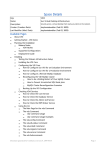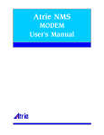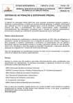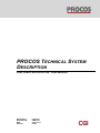
1
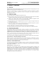
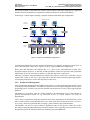
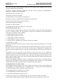
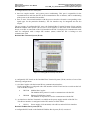
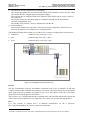
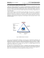
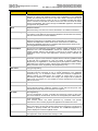
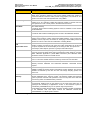
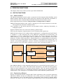
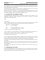
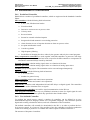
PROCOS TECHNICAL SYSTEM DESCRIPTION FUNCTIONAL SPECIFICATION / USER MANUAL Department: Document ID: Date: Version: Industrial USM_131 2013-10-11 06.02 Page 2 of 28 Proprietary Notice Date: 2013-10-11 PROCOS Technical System Description Functional Specification / User Manual File: USM_131_v06-02 PROCOS Technical System Description PROPRIETARY NOTICE Information in this document is subject to change without notice and does not represent a commitment on the part of CGI. The software described in this document is furnished under a license agreement or nondisclosure agreement. It is against the law to copy the software on any medium except as specifically allowed in the license or nondisclosure agreement. This document and its contents are the confidential property of CGI Danmark A/S. It should not be copied, reproduced, modified, altered, or circulated to any third party, in any form or media, without the prior written consent of CGI Danmark A/S. © Copyright CGI Danmark A/S, 2013 APPROVALS Version 06.02 Initials Signature Prepared by / CGI Approved by / CGI QA Approved by / CGI Date DOCUMENT CHANGE LOG Version 06.00 Date Initials Pages Affected 2008-06-19 XIMAA, OTNIE All 06.01 2012-08-31 ANWOL Pp. 1 - 2, 5, 14, 16 – 19, 21 – 24, 27 06.02 2013-10-11 PEKRF STHJE P. 1-2 Sec 2.4.2-3 Sec 5. Short Description of Change Document created Department changed. ‘Document No.’ changed to ‘Document ID’ (ILS 3318). Added reference to FSP_001. Added LogBook, SPR-IF, Modbus gateway, TwinCAT ADS Gateway, OPC Server. Removed Oracle Backup. Various minor rephrasings. ILS 3510: New CGI brand. Reporting and PLCs added. Text Objects added. Various minor rephrasings. PROCOS Technical System Description Functional Specification / User Manual File: USM_131_v06-02 PROCOS Technical System Description Page 3 of 28 Contents Date: 2013-10-11 CONTENTS 1. INTRODUCTION ......................................................................................................................... 5 1.1. SCOPE .............................................................................................................................. 5 1.2. PURPOSE ......................................................................................................................... 5 1.3. ABBREVIATIONS AND DEFINITIONS ABBREVIATIONS AND DEFINITIONS .............. 5 1.4. REFERENCE DOCUMENTS ............................................................................................ 5 2. PRODUCT OVERVIEW .............................................................................................................. 7 2.1. PROCOS ........................................................................................................................... 7 2.2. PRINCIPAL AIMS .............................................................................................................. 7 2.3. PROCOS HIGHLIGHTS .................................................................................................... 7 2.4. PROCOS CONFIGURATION............................................................................................ 8 2.4.1. Production Management ...................................................................................... 9 2.4.2. Production Control Configuration ....................................................................... 10 2.4.3. Shop-floor Control Configuration ........................................................................ 11 2.5. PROCOS SOFTWARE ARCHITECTURE ...................................................................... 15 3. PROCOS APPLICATIONS IN OVERVIEW .............................................................................. 17 4. PROCOS FUNCTIONS ............................................................................................................. 21 4.1. BATCH FUNCTIONS ...................................................................................................... 21 4.1.1. PROCOS Batch .................................................................................................. 21 4.1.2. Engineering of Recipes ...................................................................................... 21 4.2. EXTENDED CAPABILITY SYSTEM ............................................................................... 22 4.3. EXTENDED TRENDING CAPABILITIES........................................................................ 22 4.4. ALARM HANDLING ........................................................................................................ 22 5. PROCOS ENGINEERING ......................................................................................................... 23 5.1. OBJECT-ORIENTED COHERENT ENGINEERING ....................................................... 23 5.2. INTEGRATED TAG NAMING SYSTEM ......................................................................... 24 5.3. ENGINEERING OF POINTS ........................................................................................... 24 5.4. ENGINEERING OF CONTROLLERS ............................................................................. 25 5.4.1. Predefined Controller ......................................................................................... 25 5.4.2. User-defined Controller ...................................................................................... 25 5.5. CHECK AND LOAD ........................................................................................................ 26 6. 21 CFR PART 11 IN PROCOS ................................................................................................. 27 6.1. 21 CFR PART 11 INTERPRETATION ............................................................................ 27 FIGURES Figure 2-1 PROCOS Mission .............................................................................................................. 8 Figure 2-2 Medium-sized PROCOS Configuration ............................................................................. 9 Figure 2-3 PROCOS Integration of Shop-floor and Administrative Systems .................................... 11 Figure 2-4 Beckhoff BustTerminal System (IP-20) .......................................................................... 13 Figure 2-5 Beckhoff Bus Terminal System (IP-67) .......................................................................... 14 Figure 2-6 PROCOS Software Architecture ...................................................................................... 15 Figure 2-7 PROCOS - A Modular Implementation ............................................................................ 16 Figure 4-1 PROCOS Batch Applications and interfaces ................................................................... 21 Figure 5-1 PROCOS Engineering of an Analog Input ....................................................................... 23 TABLES Table 3-1 PROCOS applications ...................................................................................................... 19 Page 4 of 28 Contents Date: 2013-10-11 PROCOS Technical System Description Functional Specification / User Manual File: USM_131_v06-02 PROCOS Technical System Description (Blank Page) Page 5 of 28 Functional Specification / User Manual Date: 2013-10-11 PROCOS Technical System Description Chapter 1 Introduction File: USM_131_v06-02 PROCOS Technical System Description 1. INTRODUCTION 1.1. SCOPE This Manual is to give a technical introduction to the PROCOS system. The details of each part / applications of the system can be found in the corresponding user manuals. 1.2. PURPOSE The purpose of this document is to give you the basic technical understanding of PROCOS system. 1.3. ABBREVIATIONS AND DEFINITIONS ABBREVIATIONS AND DEFINITIONS General PROCOS abbreviations and definitions are found in Appendix A of Ref. [1]. 1.4. REFERENCE DOCUMENTS [1] USM_005 – INTRODUCTION, User Manual [2] FSP_001 – PROCOS 21 CFR Part 11 – Compliance Statement Page 6 of 28 Chapter 1 Introduction Date: 2013-10-11 PROCOS Technical System Description Functional Specification / User Manual File: USM_131_v06-02 PROCOS Technical System Description (Blank Page) Page 7 of 28 Functional Specification / User Manual Date: 2013-10-11 PROCOS Technical System Description Chapter 2 Product Overview File: USM_131_v06-02 PROCOS Technical System Description 2. PRODUCT OVERVIEW 2.1. PROCOS PROCOS from CGI has been developed to meet the tough requirements for integrated process and production control systems by the industrial sector. PROCOS is postured today as a complete system founded on a decade of experience in systems integration for high reliability applications, software development and in-depth knowledge of industrial process control. 2.2. PRINCIPAL AIMS The main design goals for the PROCOS system have been: To effectively manage supervision and control of both sequential and continues processes with the implied processing of analog and digital signals in one integrated system. To supervise and control batch processes and multi-purpose production equipment while automatically producing the necessary operational documentation. To afford maximum ease of use and high productivity for process engineers charged with the task of writing user programs. To provide the necessary openness and well-defined interface to undertake integration of systems addressing: planning, service administration and maintenance. To ensure a high degree of operational reliability and security and easy maintenance. The following chapters present the functions, facilities and components of the PROCOS system. 2.3. PROCOS HIGHLIGHTS With turbulent changes and future shocks looming everywhere in the business environment combined with an increased need to bring products to the market more quickly, and at a very low manufacturing cost, the European process industry has realised the necessity to focus on competitive key subjects like flexibility, cost-efficiency, accessibility and vendor independence. There is a growing awareness of the urgent need to define a factory automation strategy, which can be integrated as a key element in the overall information technology strategy. Viewed in this context, the PROCOS product has been focused on a number of key success factors: Open-ended ness = Integrated production environment PROCOS is based on an open-ended platform with a build in integration to administrative systems. Further, PROCOS contains facilities to perform integrated communication to all important shop floor control systems, supporting a real multi-vendor environment. Modularity = Flexible implementation The general distributed architecture of PROCOS makes it possible to implement small installations at a very low cost, and gradually upgrade these to medium and even large installations securing full usage of prior investments. Standards Based = Low life cycle cost The system is, where possible, based on available de-facto and ISO standards on hardware and software. This gives a maximum security for protection of investment, as the customer is independent of a specific hardware and software vendor. As an integrated facility PROCOS enables communication to a wide variety of 3rd party products like spreadsheets and relational databases. Basing PROCOS on available standards also secures full exploitation of the general market development towards faster and smaller units. Page 8 of 28 Chapter 2 Product Overview Date: 2013-10-11 PROCOS Technical System Description Functional Specification / User Manual File: USM_131_v06-02 PROCOS Technical System Description Proven Technology = Stability and Availability The basic platform for PROCOS is operational in quite a number of installations and has as such proven a very high degree of stability. Further, the distributed architecture secures multiple access to the production areas and thereby increasing the general availability. User friendliness = High efficiency The user interface of PROCOS is based on state-of-the-art technology increasing the operator efficiency. An object-oriented approach with a consistent look and feel focuses on the human aspects during the operation of the system. Focused on specific market segments = Optimised characteristics PROCOS has been developed and fine-tuned for a limited market segment making it possible to focus on the specific problems that these market segments are facing. Initially, the following specific segments have created the background for defining the functionality of PROCOS: Chemical and pharmaceutical industry Food and beverage industry. The PROCOS concept provides a total hardware and software solution for the overall production control as well as for the shop-floor control. Due to the modularity, and the fact that the product is based on available communication standards it is, however, possible to integrate with a wide variety of other vendors covering the shop-floor control. Figure 2-1 outlines the areas covered by the PROCOS functionality. Production Management Production Control Shop-floor Control 3’rd Party PLC System 3’rd Party PLC System Figure 2-1 PROCOS Mission PROCOS also offers a number of tools to provide the production management level with the required information, e.g. to perform the necessary documentation and validation. 2.4. PROCOS CONFIGURATION The modular construction of the PROCOS system provides a flexible means for addressing the needs for a large system handling thousands of signals as well as the needs for a small system handling a limited number of signals with fairly simple supervisory and control requirements. Page 9 of 28 Functional Specification / User Manual Date: 2013-10-11 PROCOS Technical System Description Chapter 2 Product Overview File: USM_131_v06-02 PROCOS Technical System Description One of the strengths of the PROCOS system is that modular construction principles are applied to both the software and hardware components resulting in the above mentioned flexibility. Following is a sample figure outlining a possible medium-sized PROCOS configuration. Administrative Systems Production Management Administrative Lan PROCOS Operator Station PROCOS Operator Station PROCOS Engineering Station Oracle Server Factory Lan Production Control PROCOS Area Controller PROCOS Area Controller IPC Lan (Ethernet) IPC IPC IPC IPC IPC IPC Shop-floor Control I/O Modules I/O Modules I/O Modules I/O Modules I/O Modules I/O Modules Figure 2-2 Medium-sized PROCOS Configuration As mentioned, PROCOS provides an integrated solution covering the production control level as well as the shop-floor control level. Figure 2-2 shows a typical PROCOS configuration. Please note that Ethernet with attached IPC’s is a part of the total PROCOS concept. This integrated solution, however, is optional, and the production control level provides full operational functionality for a wide selection of vendors covering the shop-floor control level. Choosing a complete, integrated PROCOS solution will, however, reduce the overall time used to engineer the system, as the user is provided with a coherent object-oriented engineering interface covering the production as well as the shop-floor control level. 2.4.1. Production Management On the production management level, PROCOS provides a very powerful integration facility, based on an Oracle relational database. The database contains all relevant engineering data for the system, and during process execution, all relevant collected data and process events, will be logged into the database. The database is accessible, from any clients attached to the administrative level, and solutions to perform documentation based on e.g. Microsoft Access or Crystal Reports can easily be implemented. CGI is able to demonstrate integrated solutions where data originating from the PROCOS system can be made available on the administrative level, either in the form of reports based on e.g. access, or by using a Web based solution thus providing a general Portal to the production data. The database can also be used to interface production plans to the process control level, thus providing an integrated Manufacturing Execution solution. This is typically used to provide an easy integration between the Enterprise Resource Planning system and PROCOS. Page 10 of 28 Chapter 2 Product Overview Date: 2013-10-11 PROCOS Technical System Description Functional Specification / User Manual File: USM_131_v06-02 PROCOS Technical System Description To provide dynamic updated process values to production management, it is also possible to implement an OPC based communication link. 2.4.2. Production Control Configuration On the production control level PROCOS is based on standard PCs and modern man/machine interface software products. The system software is a consistent management execution system offering a number of tools and services aimed against factory control in general. One of the important features of PROCOS is that it offers a powerful communication environment supporting a true client server technology, and allowing the various software modules to be freely distributed on a number of workstations. The communication is based on industry standard networking enabling easy integration to other parts of the factory. Using the PROCOS platform also enables an easy integration to a number of various PLC-based systems covering the shop-floor control level. PROCOS fulfils a majority of the basic functionality required on the production control level, but on top of PROCOS some additional functionality is added. The PROCOS add-on functionality is decided from the specific needs arising from the chosen market segments, and can be expressed in the following headlines: Batch management routines according to the S88 standard Integrated engineering and programming of the PROCOS IPC’s Object-oriented coherent engineering Full fill the 21 CFR Part 11 Standard Integrated tag naming system Extended capability System Redundancy Extended trending capabilities including on-line trending of historical data Extended alarm supervision Standard and Customized Reporting The functionality of each of these headlines is detailed in Chapter 3. The following figure gives an example of some of the integration facilities offered by PROCOS system. Page 11 of 28 Functional Specification / User Manual Date: 2013-10-11 PROCOS Technical System Description Chapter 2 Product Overview File: USM_131_v06-02 PROCOS Technical System Description Administrative Systems Production Management Administrative Lan (SQL-net) PROCOS PROCOS Factory Lan Production Control PROCOS PROCOS PROCOS Siemens IPC Lan (Ethernet) IPC IPC IPC PROCOS Allen-Bradley PROCOS Satt Control Siemens 3964R Shop-floor Control PLC’s DF1 I/O Modules I/O Modules PLC’s Modbus TCP/IP I/O Modules Figure 2-3 PROCOS Integration of Shop-floor and Administrative Systems 2.4.3. Shop-floor Control Configuration On the shop-floor control level PROCOS provides a total solution covering the communication bus systems, controllers and a range of process interface units. Communication Bus Systems The PROCOS product utilises a communication bus system. The high speed standardised Ethernet communication. Ethernet Another media to establish the intercommunication between the Area Controllers and the IPC’s is a standard Ethernet solution. All standard components can be used for this solution, including an optical fibre solution. The protocol implemented in the communication is the TCP/IP protocol. Industrial Process Controllers, IPC’s The key element of the PROCOS shop-floor control level is the IPC’s, as they are executing the actual process control and regulation tasks as well as the automatic supervision of the process. An IPC is an autonomous unit, which can be attached to one or more production areas. The IPC is a fully operational unit, also if the communication to the production control level fails. The IPC is connected to the actual plant instrumentation via a number of Process Interface Units, PIU's or I/O-modules. The scan times for an IPC are specified in four fixed time intervals from 0.0625 to 655 seconds. These four intervals are independent of each other and are configured by the customer himself in steps of 62.5 msec. Default scan classes are 0.5, 1, 5 and 30 seconds. If even quicker scan times are required, PLC's of various manufactures can be connected to the IPC. Measuring points are presented to the operator in exactly the same way irrespective of whether they are scanned through a PIU, I/O-module or a PLC. To co-ordinate the process control in different sub-plants, the IPC’s can exchange data via the IPCnet. The IPC is communicating with the Area Controller(s) via IPC-net. Data (e.g. signal values Page 12 of 28 Chapter 2 Product Overview Date: 2013-10-11 PROCOS Technical System Description Functional Specification / User Manual File: USM_131_v06-02 PROCOS Technical System Description and events) are sent to the production control level for display on the operator screens and for storage on the disk for later reporting. The IPC is released as hardware configuration. The IPC version is based on a standardised PC architecture, communicating via Ethernet. The Main Functions of the IPC’s are: Autonomous operation of sub-plants. Communication to Area Controllers and other IPCs. Execution of operator commands from the Production Control Level. Collection and dispatch of data-to-data collections. Scanning and supervision of signals. Execution of control programs. Co-ordination of the control on other IPC’s of the system. Process Interface Units, PIU’s To acquire data from and pass data to the process plant, the IPC is connected to the instrumentation level via a number of PIUs. The PIU modules are delivered in different versions dependent on which type of signal they will be handling: Digital inputs, normal or inverted Digital outputs, normal or inverted Analog inputs, 4-20 mA or 0-20 mA Analog outputs, 4-20 mA or 0-20 mA Counter inputs, 0-100Hz low pass filtered, 0-10 kHz or 0-100kHz BCD inputs, 4½ digit The PIUs galvanically separate the process control system from the instrumentation for all inputs and outputs. During operation the PIUs can be quickly replaced without affecting the operations of any other PIU units. In case of IPC failure or if the IPC execution state is changed from “Running”, the outputs will either retain their values or drop the signal, dependent on the actual user specified setup. A programmer will see the points as the interface to the process that is to be controlled or monitored. A point is a named representation of a signal coming from or going to the process. The electrical interface between IPCs and the process takes place through the process interface units. When a point is defined via the Point editor, it becomes associated with a unique PIU module and a unique channel on that module. The first step adapting a PROCOS system to an application will normally be to define and enter into the system descriptions of the actual system configuration. This is done by use of the hardware configuration editor. PIU descriptions must be entered via this editor program. Configurable Process Interface Units The configurable Process Interface Unit (PIU) contains various physical types of I/O modules each corresponding to a standard signal type. A configurable PIU is a group of I/O modules attached on a communication bus coupler or directly on the IPC5xx unit. The configurable PIU are available in two versions: The Beckhoff Bus Terminal System (IP-20) The Beckhoff Fieldbus Box System (IP-67) Connections to the process are established via connectors on each I/O module (terminal). The front plate contains indicator lamps (LED type) for power on, internal status / signal value. Page 13 of 28 Functional Specification / User Manual Date: 2013-10-11 PROCOS Technical System Description Chapter 2 Product Overview File: USM_131_v06-02 PROCOS Technical System Description A configurable PIU has two main parts: One bus coupler module and system power conditioning. This part is responsible for the communication to and from the IPC on the communication bus or ethernet, and for conditioning of the power to the attached I/O modules. Zero or more I/O terminals/modules with the process interface electronic corresponding to the signal types for the particular channel(s). The I/O interface may be integrated into the bus coupler. The two groups of configurable PIU types: the Beckhoff Bus Terminal System (IP-20) and the Beckhoff Fieldbus Box System (IP-67) can be used together on the same serial communication line(s) on an IPC or connected on the LAN attached to the IPC. Each physical communication node must be configured with a unique PIU number (name) within the IPC it belongs to and communicates with. Beckhoff Bus Terminal System (IP-20) Figure 2-4 Beckhoff BustTerminal System (IP-20) A configurable PIU based on the Beckhoff Bus Terminal System (IP-20) consists of one of the following configurations: 1) One Bus Coupler with the internal K-bus communication interface: Each Coupler Box is configured with a PIU number in ENG-TOOL and on a switch on the left side of the Bus Coupler. BK7300 Modbus Bus Coupler. The Modbus RTU protocol is used to communicate with the IPC. BK9000 Ethernet TCP/IP Bus Coupler. The Modbus TCP protocol is used to communicate with the IPC. 2) An interface to the Bus Terminals is available on the power supply module of the IPC53x. This K-bus interface is configured with a PIU number in ENG-TOOL. IPC53x Power supply (CX1100-0003) with a K-bus and an IP-Link interface. Beckhoff Fieldbus Box System (IP-67) A configurable PIU based on the Beckhoff Fieldbus Box System (IP-67) consists of Page 14 of 28 Chapter 2 Product Overview Date: 2013-10-11 PROCOS Technical System Description Functional Specification / User Manual File: USM_131_v06-02 PROCOS Technical System Description 1) One Ethernet TCP/IP Coupler Box (IL230x-B90x): The Coupler Box gathers the I/O data from the Extension Box modules over the IP-Link1 cable. The Coupler Box has 4 digital inputs and 4 digital outputs. Each Coupler Box is configured with a PIU number in ENG-TOOL and on a rotary switch on the coupler box. Because the coupler box has input/output it is automatically added as the first terminal (IL230x) in Engineering Tool. The Modbus TCP protocol is used to communicate with the IPC. 2) Extension Boxes: The extension modules are connected via the IP-Link to the Coupler Box. Extension boxes increases the number of I/O channels on a configurable PIU. The Beckhoff Fieldbus Box modules are available with 3 connector configurations to the process: 8 mm(Ø 8): Connector 8 mm, snap type, 3 pins M8: Connector M8, screw type, 3 pins M12: Connector M12, screw type, 5 pins IPC 531 K-Bus with Bus Terminals Modbus (TCP/IP) Ethernet Switch IP67 Coupler Box with Extension Box Modules Figure 2-5 Beckhoff Bus Terminal System (IP-67) I/O-bus The IPC communicates with the I/O-modules connected to the LAN via Ethernet TCP/IP Bus Couplers with local Bus Terminals and with up to 4 I/O-buses, and each of these may be distributed in the plant allowing a maximum bus length of up to 1 km. The function of the bus is to transfer signal values between the process and the IPC’s. The I/O-buses use a standard RS-422/485 communication with selectable transmission speed and connect up to 254 I/O-addresses to one single IPC. The comm. uses an error detecting protocol. PLCs It is also possible to connect PLC’s of different manufactures via the 4 I/O-buses. PLC’s supporting Modbus/TCP can be connected via Ethernet. 1 IP-Link is an interference-free fiber optic communication link with a transmission rate of 2 Mbits/s Page 15 of 28 Functional Specification / User Manual Date: 2013-10-11 PROCOS Technical System Description Chapter 2 Product Overview File: USM_131_v06-02 PROCOS Technical System Description 2.5. PROCOS SOFTWARE ARCHITECTURE Applications, PROCOS applications, are designed for implementation in a distributed multi-vendor environment. Applications adhere to an architecture where all communication between two parties takes place through a third entity, the PROCOS Environment. PROCOS Applications communicate by the use of the object-oriented Manufacturing Message Specification (MMS) protocol for interchange of information. This ensures a hitherto unheard level of flexibility in implementation of factory automation. Another important aspect of the PROCOS product philosophy is the provision of an application program interface defined on the basis of international standards. This allows the development of applications and gateways by third party on the basis of a public domain C programming interface. Furthermore, the fact that all inter-process communication goes through a third entity, provides the foundation for the development of applications, which integrate easily with products from CGI and its business partners. Graphical Presentation Services Applications: - MIMIC - ALARMDISP, LOGDISP - TREND Admin Gateway - DB-IF (SQL*net) - SQL-GWY Enablers: - ENG-TOOL - PICTOOL - CTL-TOOL - BAT-TOOL PROCOS Other: - Crystal Reports - ORACLE Tools Process - MMS - GATEWAYS - Batch Management - COLLECT, LOG - CTL-EXEC Figure 2-6 PROCOS Software Architecture A key to any successful network architecture is the inter-process communication philosophy and implementation. Applications are developed and communicate using the logical referencing defined by the ISO 9506 international standard (Manufacturing Message Specification - MMS). Applications developed in PROCOS are therefore independent of applications with which they communicate, whether these are resident in the same node or in another PROCOS node. This highly facilitates distribution of applications. All inter-process communication takes place in compliance with international standards; all applications use the same programming interface, part of the PROCOS Environment. Environment shall reside on any PROCOS station; in a multi-station network it binds the stations together in a plant-wide network transparent to individual applications and thus the end-user. Page 16 of 28 Chapter 2 Product Overview Date: 2013-10-11 PROCOS Technical System Description Functional Specification / User Manual File: USM_131_v06-02 PROCOS Technical System Description Mapplication Overview ORACLE DATABASE SERVER VISUALISATION ALARM MANAGEMENT DATA ACQUISITION SQL BATCH MANAGEMENT REPORTING VALIDATION SEQUENCE CONTROL ENGINEERING APPLICATIONS PROCOS Communication Environment PROCOS GATEWAYS GATEWAY API 3rd PARTY APPLICATION API Figure 2-7 PROCOS - A Modular Implementation For the Operator Interface applications, the emphasis has been put on providing the operator with a real-time graphical intuitive interface. There will, in general, be applications from this group in all PROCOS nodes in a network. OPC Data Access Server and on-line relational database provide the platform for the data analysis tools available. The approach made has been to integrate recognised standard products into PROCOS, specifically ORACLE®'s relational database products. PROCOS applications provide the mechanisms for making process variables available as live data. The Data Capture applications provide for storage of scanned data and unsolicited events, operator commands, and data Information Reports. The PROCOS architecture allows the user to decide if each node in a network is to be equipped with e.g. an event logging application for maximum resilience or if all events are being reported to a single destination. Gateways provide the interface to the process supporting proprietary equipment. These gateways behave like server devices and can as such be accessed from other PROCOS systems as well as from other systems using MMS services. An embedded relational database serves as the platform for retaining engineering data, e.g. configuration and conversion constants which are to be down-loaded as tables via the PROCOS network to e.g. operator interface or Gateway applications situated on remote PROCOS nodes. This facilitates engineering from a central station. The Operator Interface applications are developed using PROCOS application enablers. These are characterised by their ease of use. Multi-windowed techniques have been applied to further improve user-efficiency during development and to secure that the user may display all needed information on the screen simultaneously. Page 17 of 28 Functional Specification / User Manual Date: 2013-10-11 PROCOS Technical System Description Chapter 3 PROCOS Applications in Overview File: USM_131_v06-02 PROCOS Technical System Description 3. PROCOS APPLICATIONS IN OVERVIEW This section is devoted to a brief explanation of the role played by each application in the PROCOS system. The applications are listed alphabetically Application Description ACCESS-CONTROL Advanced Access Control. User Access Control providing centralized check of user identity. It is installed on all Engineering, Gateway and Operator stations as an add-on to WORKBENCH in a system with advanced access control. The Advanced Access Control is configured through User Administration Tool. Token Access Control. The package enabling the use of a token reader is an add-on to the WORKBENCH and Advanced User Access Control. Each operator may be equipped with a RFID (a token) and a RFID reader may be mounted near the keyboard of each operator station. When an operator is in the range of the keyboard the RFID reader will read the RFID tag and send the TokenID to the PROCOS system. The TokenID is then used to identify the user for the system. The association between TokenIDs and operators is defined in the Advanced User Administration Tool. Bar Code Access Control. The package enabling the use of a bar code reader is an add-on to the WORKBENCH and Advanced User Access Control. Each operator may be equipped with a Bar Code (a token) and a Bar Code reader may be mounted near the keyboard of each operator station. The Bar Code is then used to identify the user for the system. The association between Bar Code IDs and operators is defined in the Advanced User Administration Tool. User Tool Administration Advanced Access Administration Tool. This package is used to install a user logon server and a tool used to configure the centralized check of user identity used by the Advanced Access Control. It is installed on one pc with access to an ORACLE® database. ASCII-I/O The ASCII-I/O application provides a real-time interface between PROCOS and an external serial ASCII device, e.g. a bar code reader, a standalone weight, etc. It is responsible for decoding ASCII strings from the connected equipment. ALARMDISP Alarm display provider. Alarm display.ALARMDISPLAY is the operator interface to the LOG/event management server. Alarms are shown with a time stamp and can be acknowledged BAT-EXEC PROCOS Batch Executor. The Batch Executor application is responsible for loading of recipe values to the process equipment. The batch executor is positioned on the PC level enabling it to see all process equipment. The Batch Executor is configured using BAT-TOOL. BAT-TOOL Batch configuration. BAT-TOOL is an add-on to ENG-TOOL used to write/maintain batch recipes. The batch executor executes these recipes. BAT-TOOL works as an integrated part of ENG-TOOL. ENG-TOOL is required. COLLECT Responsible for data collection. Data is retrieved from the process either on request (operator or from IPC sequence) or periodic. The data is saved in cyclic files on the harddisk. Data can be exported to ORACLE® by use of e.g. DB-IF. COLLECT is engineered using ENG-TOOL. CTL-EXEC Controller Executor. Executes control sequences. CTL-EXEC executes sequence controllers defined on PC level. The control sequences are engineered through ENG-TOOL (the CTLTOOL add-on). CTL-TOOL Configuration of sequence controllers (CTL-EXEC). Tool for configuration of sequence controllers executed by the CTL-EXEC application. CTL-TOOL is an add-on to ENG-TOOL, and runs as an integrated part of ENG-TOOL. As a consequence, ENG-TOOL is required. Page 18 of 28 Chapter 3 PROCOS Applications in Overview Date: 2013-10-11 PROCOS Technical System Description Functional Specification / User Manual File: USM_131_v06-02 PROCOS Technical System Description Application Description DAT-EXEC Data Set Executor. Mapping of values and variables to/from other applications in the PROCOS system. The Data Set Executor has a “Load” and a “Store” command and may be activated from the sequence code in an IPC. It is possible to define that when a “Store” command is executed the values stored in the data set should be written back to the database. This is done through the ENGDBIF application. DAT-EXEC is engineered using ENG-TOOL. DB-IF Database interface. Data retrieved by COLLECT and LOG is transferred to an ORACLE® database. DB-IF Archiving DB-IF Data Archiving. Tool used to move data from the production database to archive files and restoring data from the archives in a restore database. ENG-TOOL Engineering Tool,. PROCOS configuration tool enabling off-line configuration of workstations, hardware and application software. ENG-TOOL saves data to an ORACLE® Engineering database. ENG-TOOL is equipped with backup/restore functions etc. A running ORACLE® database is required ENVIRONMENT Environment and PROCOS LAN interface enabling multiple workstations on the PROCOS LAN. This ENVIRONMENT extends the PROCOS software bus to multiple operator stations. And provides a common set of services used by the applications used to access other applications, operating system, hardware and network ESign Tool Electronic Signature (ES) is intended to be used as a replacement for paper written documents, logs etc. ES in PROCOS complies with the rules and guidelines stated by the FDA. ES is engineered in a way very similar to operator capabilities in Engineering Tool. Applicable to: values being set by the operator in Mimic, actions performed by the operator in Mimic, alarms being acknowledged in Alarm Display, Batch production and on engineering data (Engineering Tool). GWY-TOOL Tag type engineering. IPC Executor IPC Executor (requires Basic Software and dongle). Education Industrial Process Controller Executer configured as one or several applications in the PROCOS environment e.g. on an IPCGWY station with other PROCOS mapplications. Without support for PIU/PLC-bus. The number of active IPCs in the IPC Executor(s) is limited by a number in the dongle. The dongle must be updated if further IPCs are required. It is not possible to use this education IPC as a spare part for an IPCxxx. IPC-GWY Gateway between IPCs and PROCOS system IPC Std. Pictures IPC related MIMIC standard pictures. These standard pictures enable the operator to load, start and stop IPCs. Also standard pictures for sequences and points are supplied. IPC TOOL IPC engineering. Tool for configuration of points, controllers and sequences running at IPC level. IPC tool is an add-on to ENG TOOL and runs as an integrated part of ENG TOOL. LOG Cyclic LOG handler. LOG contains alarms and events generated by controllers and operator interventions. LOG is used by higher level applications as alarm/event server. LogBook LOGBOOK is intended to replace most of the manual logs maintained at various sites. This helps to ensure that operator interventions beyond the normal level of operation is properly tracked and commented. The LOGBOOK Mapplication is used to display and comment LogBook events. LOGDISP LOG report display. This application shows all information existing in LOG Page 19 of 28 Functional Specification / User Manual Date: 2013-10-11 PROCOS Technical System Description Chapter 3 PROCOS Applications in Overview File: USM_131_v06-02 PROCOS Technical System Description Application Description MIMIC Mimic display provider. MIMIC is the operators’ interface to the process. MIMIC enables the operator to monitor and manual control the entire process using graphics, text, trends etc. The operator uses the mouse and keyboard when using MIMIC. Modbus Gwy The Modbus Gateway provides a real-time interface between PROCOS and the Modbus PLCs. The gateway enables the PROCOS system to perform read and write operations of one or more points in the data area of the PLCs. OPC-GWY OPC Client Gateway. Provides an OPC interface enabling dynamic access to variables in OPC Servers outside PROCOS. OPC-SRV OPC Server. Provides an OPC interface enabling dynamic access to the PROCOS variables. PIC-TOOL Picture Engineering Tool. Graphic tool for creation of static and dynamic MIMIC displays. In PIC-TOOL tags, variables, actions, help texts, menu bars etc. belonging to each MIMIC picture are defined. PIC-TOOL is also used for modification of existing Mimics. Report Web Server and Report Web Client All PROCOS Standard Reports are accessed through a web interface. The web interface contains one page for each report from which parameters can be set and the report requested for on-screen display or for saving on disk. The reports are: Batch Report, Alarm Report, Operator Log Report and Collect Report. SMS-Tool SMS tool enables the ability to engineer alarm groups. Alarms matching an alarm group may be sent by SMS. Alarm routing in PROCOS is partly based on a system called: “NMSView Application” (“Zonith NMS Extensions”) from NMSView which handles the transfer of alarms to a SMS-device. SPRIF SPRIF receives data collected by one or more COLLECT Mapplications and saves them in .TXT format. SPRIF maintains a directory structure of such data-files. SQL-GWY SQL Database Gateway. Gateway between PROCOS and ORACLE® database. ORACLE® license required. TREND Trend Curve display. TREND is capable of showing trends of interesting process variables. The process variables are selected by the user who also can change sampling period, time horizon etc. TwinCAT ADS Gateway The PROCOS Technical System Description provides a real-time interface between PROCOS and a TwinCAT system. The gateway enables the PROCOS system to perform read and write operations of one or more points in the data area of the PLC(s) and/or I/O administered by TwinCAT. WORKBENCH Operator Workbench. The PROCOS desktop used by the operator for the most basic tasks such as login/logout and start/stop of applications. Access to the PROCOS system is maintained by WORKBENCH by use of operator login and password. The Workbench includes the PROCOS LAN option enabling multiple workstations on the PROCOS LAN. This option extends the PROCOS software-bus: ENVIRONMENT to multiple operator stations. Table 3-1 PROCOS applications Page 20 of 28 Chapter 3 PROCOS Applications in Overview Date: 2013-10-11 PROCOS Technical System Description Functional Specification / User Manual File: USM_131_v06-02 PROCOS Technical System Description (Blank Page) Page 21 of 28 Functional Specification / User Manual Date: 2013-10-11 PROCOS Technical System Description Chapter 4 PROCOS Functions File: USM_131_v06-02 PROCOS Technical System Description 4. PROCOS FUNCTIONS This chapter details some of the key features provided with PROCOS. 4.1. BATCH FUNCTIONS 4.1.1. PROCOS Batch The PROCOS distributed control system is proposed with the integrated batch handling system PROCOS Batch. PROCOS Batch, which comes fully integrated in the PROCOS environment, is based on the ISA-S88.01 standard. PROCOS Batch features powerful facilities such as: Recipe organisation and execution in Unit procedures, Unit Operations and Phases. Enhanced train-plant facilities using ‘Aliases’, utilizing use of one recipe element on several units. This approach also minimizes validation efforts. Clear separation of ISA-S88.01 physical and procedural models, enhancing functionality in multipurpose plants. Support of Default values on several levels utilizing ‘general recipes’ Easy recipe development, using Parameter Lists for commonly used setpoint sets. PROCOS batch consists of two standard software applications. A configuration tool, BAT-TOOL, is installed as a fully integrated part of the PROCOS configuration tool ENG-TOOL. All engineering of recipes is performed using BAT-TOOL. The second application, BAT-EXEC (Batch Executor), is the batch engine, and is responsible for actual execution of the batch production. The BAT-EXEC application is installed anywhere on a standard PROCOS workstation, and interacts directly with the operator interface (MIMIC), with the PROCOS controllers (IPC’s) or with the ‘soft controller application’ (used for execution of production line sequential logic or phases on the PC level) CTL-EXEC (Controller executor). This is presented in Figure 4-1. Engineering BAT-TOOL (Recipe Engineering) Process Operation Download BAT-EXEC (Batch Execution) Manual Execution MIMIC (Operator Interface) Automatic Execution IPCs (Controllers) Automatic Execution CTL-EXEC (Soft Logic) Figure 4-1 PROCOS Batch Applications and interfaces Since PROCOS Batch is a fully integrated product, there is no special batch operator interface, as is the case for some other systems. The batch related information is provided in detailed graphics, which are nicely integrated in the normal operator interface. Thus, the operator maintains full control of the batch process by simultaneous interaction with both process graphics and batch related pictures. Also, messages etc. are handled from the normal PROCOS operator interface. 4.1.2. Engineering of Recipes Recipes are engineered off-line (using the BAT-TOOL application), and saved in the engineering ORACLE® database. Recipes are transferred to the on-line system by download of the recipes from Engineering Tool to the Batch Executor. Downloaded recipes cannot be changed during operation. The recipes can only be changed using Engineering Tool and subsequently download. Page 22 of 28 Chapter 4 PROCOS Functions Date: 2013-10-11 PROCOS Technical System Description Functional Specification / User Manual File: USM_131_v06-02 PROCOS Technical System Description Recipes are edited in a spreadsheet-like interface, where setpoints are assigned to each procedural element (i.e. procedures, operations and phases) in the recipe. 4.2. EXTENDED CAPABILITY SYSTEM PROCOS contains an extended capability system securing a safe operation of the plant. During engineering it is possible to define a number of operator profiles. Each of these profiles contains a positive or negative list of objects on which the operator may or may not operate or view. When a given operator logs in to PROCOS he will be attached to one of these operator profiles. When specifying the capabilities, the engineer can enter explicit names or name masks for the following types of objects: Area Unit Process object Picture Picture actions System maintenance operations. 4.3. EXTENDED TRENDING CAPABILITIES PROCOS contains a powerful trending facility, whereby the user on selected workstations may define a number of TREND windows, each containing up to 8 different process variables. The variables being trended may either be on-line live data, or historical data collected by the COLLECT Mapplication. 4.4. ALARM HANDLING In order to provide the operator with a possibility to overview the general alarm situation in the plant, each operator station can be equipped with an alarm panel, attached to the normal detailed alarm window. This alarm panel shows the alarm status for each area defined in the plant, and indicates overall figures like e.g. number of not acknowledged high priority alarms. From the alarm panel it is possible to select a specific MIMIC picture engineered to display selected process details. Page 23 of 28 Functional Specification / User Manual Date: 2013-10-11 PROCOS Technical System Description Chapter 5 PROCOS Engineering File: USM_131_v06-02 PROCOS Technical System Description 5. PROCOS ENGINEERING Within the scope of PROCOS an engineering environment is created. As an integrated part of this environment the IPC engineering is performed. To engineer the IPC’s, a number of editors have been defined: Hardware configuration editor defining the physical lay-out of the IPC’s and attached I/O-modules. Point definition editor defining the digital, analog, counter or text objects. Editing of the controllers is performed using an editor of free choice. The editors have been designed with a graphical user interface, and following is an example of the designed analogue input point editor. Figure 5-1 PROCOS Engineering of an Analog Input For each of the objects a unique tag-name is attached. For a detailed description of the tag-name, please refer to Section 5.2. During the editing session, the engineer will be assisted with an extensive on-line help facility, and at download the various IPC definitions will be checked for correctness and consistency. It is possible to get extensive documentation of the engineering definitions. Also facilities for performing back-up and restore of the engineering definitions are provided. 5.1. OBJECT-ORIENTED COHERENT ENGINEERING Once the objects have been defined, they can be referred to from the remaining engineering tools. Hence, when alarms, historical collections, or picture elements are engineered, the defined objects are referenced using the unique tag-name identification. The coherence is achieved by having the data defined in a common relational database, and as front-end to the database an object-oriented tool called “Object Studio” (from Cincom) has been chosen. Page 24 of 28 Chapter 5 PROCOS Engineering Date: 2013-10-11 PROCOS Technical System Description Functional Specification / User Manual File: USM_131_v06-02 PROCOS Technical System Description The coherence also covers the engineering of MIMIC pictures used for visualising the process, and for generating these pictures a symbol library concept is available. Using this symbol library speeds up the engineering process significantly. An extensive library of process relevant symbols is predefined and will be delivered with PROCOS. This includes symbols like valves, motors, PID regulators, etc. Further, for each type of object, like e.g. an analog input point, standard detailed pictures have been defined. This feature is of special value for performing test and commissioning of a given plant. Also the IPC controllers will have their own type of standard picture. 5.2. INTEGRATED TAG NAMING SYSTEM An integrated tag-name system based on the conventions outlined in the S88 standard has been implemented in PROCOS. Hence, according to S88, the objects in a factory can be named according to the following hierarchy: Area Unit Process Object. A process object specifies the lowest level of the process and may reflect simple I/O's like a digital input. The engineered process objects will normally contain a number of parameters like: Description Used when appropriate Unit E.g. used in reports Min Used as default min limit e.g. in curves Max Used as default max limit e.g. in curves A process object refers to one and only one unit. A unit is normally a part of the plant that is operated relatively independent of other parts of the plant. It consists of a number of process objects. An example of a unit could be a tank. According to S88, a unit may operate on only one product at a time. A unit refers to one and only one area. An area is a logically or physically grouping of a number of units, or a number of process control objects. In PROCOS the area concept is used to specify groups of objects on which some coherent operations e.g. like definition and transfer of authority between operators can take place. Usage of the unit and area definition is optional, and can be omitted making naming in smaller sites more simple. When entering tag names, the user is presented with two fields. One field is used to specify the process object, and one field is used to specify a combination of the area and unit name with a defined delimiter. The display of each of the two fields has a width of 12 characters, but it is possible to specify up to 32 characters. 5.3. ENGINEERING OF POINTS The engineering platform has an object-oriented structure, where it is possible to define a number of process control objects like e.g. an analog input. For each of the defined objects parameters like hardware address, tag-name, alarm text, etc. can be specified. Page 25 of 28 Functional Specification / User Manual Date: 2013-10-11 PROCOS Technical System Description Chapter 5 PROCOS Engineering File: USM_131_v06-02 PROCOS Technical System Description 5.4. ENGINEERING OF CONTROLLERS 5.4.1. Predefined Controller PROCOS has a number of predefined controllers, which are engineered in the Standard Controller Editor: PID controllers with the following built-in functions: P, PI, I, PD, PID functional modes Error dead-band Derivative action on error or process value Velocity mode Reversed action Internal or external calculated setpoint Integrator hold and automatic reset-windup protection Alarm function in case of setpoint deviation or alarm on process values Set point initialisation at start Cascade regulation High frequency filtering Possibilities of changing the above either by the operator and/or by the control programs. Delay compensation controllers are used together with PID-controllers in processes with large delays. A process model is defined and used as input for the PID-controller to compensate for calculated or measured delays caused by dead time. Program generators calculate analog signal values as a function of the time. Function generators calculate analog signal values as a function of analog input values. Totalises sum up analog signals. The summation can be reset and stopped temporarily. Filter controllers with the following built-in functions: 1. to 4. order filter Standard or general set-up Motor controllers monitor and control motor operations. Valve controllers monitor and control valve operations. Digital delay controllers with independent ON and OFF delays on digital signals. The controllers can also be used to eliminate noise on signals. Send and receive controllers are used for signal communication via the IPC-net. Time program controllers allow up to 6 predefined variations in time of a digital signal for each weekday as well as for three special days specified in the Calendar editor. 5.4.2. User-defined Controller To perform the actual process control, a number of controllers can be defined in an easy understandable high-level language named ALL (ALgorithm Language). The controllers perform digital and/or analog calculations and test, and issue commands to other controllers. The defined controllers will normally be downloaded to the IPC’s, in order to perform the lowlevel process control. It is, however, also possible to have the controllers executed on production control level making it possible to co-ordinate the control sequences defined on the IPC’s. The structure of Sequence Controllers. Page 26 of 28 Chapter 5 PROCOS Engineering Date: 2013-10-11 PROCOS Technical System Description Functional Specification / User Manual File: USM_131_v06-02 PROCOS Technical System Description A sequence controller contains the following: "STATES", "TRANSITION CONDITIONS" and "TRANSITION ACTIONS" between states. Parameters, timers and operator messages. Interface to points, standard controllers, other sequence controllers, recipes, data collections, reports and operator functions. In order to control a sequence of events, the controller must be capable of remembering where it is in the sequence. This is the basis of the state concept used in the PROCOS system. In principle, a state is a memory element used to keep track of how the sequence controller is proceeding in its task. The transition from one state to another will take place when a transition condition is met. The transition can be accompanied by a transition action. 5.5. CHECK AND LOAD The check and load programs are used to: Check that all definitions of I/O-modules, PLC's points and controllers are defined in consistent way. There must not be any ambiguities or conflicts between objects. Errors in the user programming are displayed on the screen and/or on the printer. Transfer (download) or remove user programs to/from the IPC’s. Only checked objects without errors can be transferred to the IPC’s. For security reasons, active objects cannot be removed from the IPC’s; they must first be blocked. Manipulate the IPC state to ensure that things are done in the correct order. The user programs are transferred to the IPC’s either separately (one single object at a time) or for an entire IPC. Page 27 of 28 Functional Specification / User Manual Date: 2013-10-11 PROCOS Technical System Description Chapter 6 21 CFR Part 11 in PROCOS File: USM_131_v06-02 PROCOS Technical System Description 6. 21 CFR PART 11 IN PROCOS 6.1. 21 CFR PART 11 INTERPRETATION In general 21 CFR Part 11 is a very general regulation, which needs to be interpreted with respect to PROCOS in order to gain the insight needed on the subject. The current opinion is that 21 CFR Part 11, including various published interpretations, is focusing on the following relevant key issues: System Validation Access Control/Limited Access Audit Trails Human- and Machine Readable Record Record Retention Electronic Signatures For further information see Ref. [2] FSP_001 – PROCOS 21 CFR Part 11 – Compliance Statement. Page 28 of 28 Chapter 6 21 CFR Part 11 in PROCOS Date: 2013-10-11 PROCOS Technical System Description Functional Specification / User Manual File: USM_131_v06-02 PROCOS Technical System Description (Blank Page)