1
Operation and Service Guide
Agilent Technologies
8648A/B/C/D Signal Generator
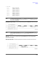
Serial Number Prefixes:
This manual applies directly to the following model/serial prefix
combinations and below.
8648A
8648B
8648C
8648D
3847A/U
4037A/U
4037A/U
4037A/U
Part Number 08648-90048
Printed in USA
March 2001
Supersedes September 2000
© Copyright 1996, 1998-2001 Agilent Technologies, Inc.
.
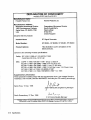
WEEE Directive
This product complies with the WEEE Directive (2002/96/EC) marking requirements.
The affixed label indicates that you must not discard this electrical/electronic product
in domestic household waste.
Product Category: With reference to the equipment types in the WEEE Directive
Annex 1, this product is classed as a “Monitoring and Control instrumentation”
product.
Do not dispose in domestic household waste.
To return unwanted products, contact your local Agilent office, or see
http://www.agilent.com/environment/product/ for more information.
Printed in USA
June 2005
Contents
1. Operation
Quick Overview . . . . . . . . . . . . . . . . . . . . . . . . . . . . . . . . . . . . . . . . . . . . . . . . . . . . . . . . . . . . .1-2
1. Power Key . . . . . . . . . . . . . . . . . . . . . . . . . . . . . . . . . . . . . . . . . . . . . . . . . . . . . . . . . . . . . .1-2
2. Display . . . . . . . . . . . . . . . . . . . . . . . . . . . . . . . . . . . . . . . . . . . . . . . . . . . . . . . . . . . . . . . . .1-2
3. Function and Data Keys . . . . . . . . . . . . . . . . . . . . . . . . . . . . . . . . . . . . . . . . . . . . . . . . . . .1-3
4. Increment Set Keys. . . . . . . . . . . . . . . . . . . . . . . . . . . . . . . . . . . . . . . . . . . . . . . . . . . . . . .1-4
5. Knobs . . . . . . . . . . . . . . . . . . . . . . . . . . . . . . . . . . . . . . . . . . . . . . . . . . . . . . . . . . . . . . . . . .1-4
6. MEMORY . . . . . . . . . . . . . . . . . . . . . . . . . . . . . . . . . . . . . . . . . . . . . . . . . . . . . . . . . . . . . .1-4
7. Modulation Source . . . . . . . . . . . . . . . . . . . . . . . . . . . . . . . . . . . . . . . . . . . . . . . . . . . . . . .1-5
1a. Operation Examples
Setting the RF Output Signal . . . . . . . . . . . . . . . . . . . . . . . . . . . . . . . . . . . . . . . . . . . . . . . . .1a-3
Setting the Frequency. . . . . . . . . . . . . . . . . . . . . . . . . . . . . . . . . . . . . . . . . . . . . . . . . . . . . .1a-3
Setting the Amplitude. . . . . . . . . . . . . . . . . . . . . . . . . . . . . . . . . . . . . . . . . . . . . . . . . . . . . .1a-3
Turn on the RF Output. . . . . . . . . . . . . . . . . . . . . . . . . . . . . . . . . . . . . . . . . . . . . . . . . . . . .1a-3
Setting the Modulation . . . . . . . . . . . . . . . . . . . . . . . . . . . . . . . . . . . . . . . . . . . . . . . . . . . . .1a-4
Incrementing or Decrementing the RF output Signal . . . . . . . . . . . . . . . . . . . . . . . . . . . . . .1a-5
Preliminary Steps . . . . . . . . . . . . . . . . . . . . . . . . . . . . . . . . . . . . . . . . . . . . . . . . . . . . . . . . .1a-5
Using the Knob . . . . . . . . . . . . . . . . . . . . . . . . . . . . . . . . . . . . . . . . . . . . . . . . . . . . . . . . . . .1a-5
Using the Increment Keys . . . . . . . . . . . . . . . . . . . . . . . . . . . . . . . . . . . . . . . . . . . . . . . . . .1a-5
Using the Memory Registers . . . . . . . . . . . . . . . . . . . . . . . . . . . . . . . . . . . . . . . . . . . . . . . . . .1a-7
Saving Instrument Setting in Register Sequences . . . . . . . . . . . . . . . . . . . . . . . . . . . . . . .1a-8
Deleting a Register from the Sequence . . . . . . . . . . . . . . . . . . . . . . . . . . . . . . . . . . . . . . .1a-11
Renumbering the Registers in a Sequence . . . . . . . . . . . . . . . . . . . . . . . . . . . . . . . . . . . .1a-12
Inserting a Register in a Sequence . . . . . . . . . . . . . . . . . . . . . . . . . . . . . . . . . . . . . . . . . .1a-13
Offsetting the RF Output from a Reference . . . . . . . . . . . . . . . . . . . . . . . . . . . . . . . . . . . . .1a-16
Setting the Reference Value . . . . . . . . . . . . . . . . . . . . . . . . . . . . . . . . . . . . . . . . . . . . . . . .1a-16
Offsetting the RF Output . . . . . . . . . . . . . . . . . . . . . . . . . . . . . . . . . . . . . . . . . . . . . . . . . .1a-17
Holding the Output Attenuator Range . . . . . . . . . . . . . . . . . . . . . . . . . . . . . . . . . . . . . . . . .1a-19
Set the Amplitude Level . . . . . . . . . . . . . . . . . . . . . . . . . . . . . . . . . . . . . . . . . . . . . . . . . . .1a-19
Holding the Attenuator. . . . . . . . . . . . . . . . . . . . . . . . . . . . . . . . . . . . . . . . . . . . . . . . . . . .1a-19
Adjusting the Amplitude . . . . . . . . . . . . . . . . . . . . . . . . . . . . . . . . . . . . . . . . . . . . . . . . . .1a-20
Setting a User Selectable Modulated Frequency and Waveform
(Option 1E2 or 1EP Only) . . . . . . . . . . . . . . . . . . . . . . . . . . . . . . . . . . . . . . . . . . . . . . . . . . .1a-21
Setting the Modulation Level . . . . . . . . . . . . . . . . . . . . . . . . . . . . . . . . . . . . . . . . . . . . . . .1a-21
Setting the Modulated Waveform. . . . . . . . . . . . . . . . . . . . . . . . . . . . . . . . . . . . . . . . . . . .1a-21
Setting the Modulated Frequency . . . . . . . . . . . . . . . . . . . . . . . . . . . . . . . . . . . . . . . . . . .1a-22
Signaling a Numeric-Type FLEX Pager (Option 1EP Only) . . . . . . . . . . . . . . . . . . . . . . . .1a-23
Setting Up Pager Encoding . . . . . . . . . . . . . . . . . . . . . . . . . . . . . . . . . . . . . . . . . . . . . . . .1a-23
Entering Pager Encoding Settings . . . . . . . . . . . . . . . . . . . . . . . . . . . . . . . . . . . . . . . . . . .1a-24
Selecting the Format Settings . . . . . . . . . . . . . . . . . . . . . . . . . . . . . . . . . . . . . . . . . . . . . .1a-24
Selecting the Data Rate and Pager Type Settings . . . . . . . . . . . . . . . . . . . . . . . . . . . . . .1a-25
Selecting the Message Settings . . . . . . . . . . . . . . . . . . . . . . . . . . . . . . . . . . . . . . . . . . . . .1a-26
Selecting the Transmission Repetitions and Amplitude. . . . . . . . . . . . . . . . . . . . . . . . . .1a-26
Selecting the Pager Capcode (Address) . . . . . . . . . . . . . . . . . . . . . . . . . . . . . . . . . . . . . . .1a-27
Selecting the Protocol Settings. . . . . . . . . . . . . . . . . . . . . . . . . . . . . . . . . . . . . . . . . . . . . .1a-28
Selecting the Roaming Mode Settings . . . . . . . . . . . . . . . . . . . . . . . . . . . . . . . . . . . . . . . .1a-29
Encoding . . . . . . . . . . . . . . . . . . . . . . . . . . . . . . . . . . . . . . . . . . . . . . . . . . . . . . . . . . . . . . .1a-29
ix
Contents
1b. Operation Reference
Frequency and Amplitude. . . . . . . . . . . . . . . . . . . . . . . . . . . . . . . . . . . . . . . . . . . . . . . . . . . . 1b-2
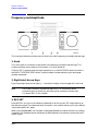
1. Knob . . . . . . . . . . . . . . . . . . . . . . . . . . . . . . . . . . . . . . . . . . . . . . . . . . . . . . . . . . . . . . . . . 1b-2
2. Digit-Select Arrow Keys. . . . . . . . . . . . . . . . . . . . . . . . . . . . . . . . . . . . . . . . . . . . . . . . . . 1b-2
3. REF SET . . . . . . . . . . . . . . . . . . . . . . . . . . . . . . . . . . . . . . . . . . . . . . . . . . . . . . . . . . . . . . 1b-2
4. REF ON/OFF . . . . . . . . . . . . . . . . . . . . . . . . . . . . . . . . . . . . . . . . . . . . . . . . . . . . . . . . . . 1b-3
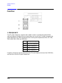
Function . . . . . . . . . . . . . . . . . . . . . . . . . . . . . . . . . . . . . . . . . . . . . . . . . . . . . . . . . . . . . . . . . . 1b-4
1. FREQUENCY . . . . . . . . . . . . . . . . . . . . . . . . . . . . . . . . . . . . . . . . . . . . . . . . . . . . . . . . . . 1b-4
2. AMPLITUDE . . . . . . . . . . . . . . . . . . . . . . . . . . . . . . . . . . . . . . . . . . . . . . . . . . . . . . . . . . 1b-5
3. FM, AM, ΦM . . . . . . . . . . . . . . . . . . . . . . . . . . . . . . . . . . . . . . . . . . . . . . . . . . . . . . . . . . . 1b-5
Setting Up the Pager Encoder . . . . . . . . . . . . . . . . . . . . . . . . . . . . . . . . . . . . . . . . . . . . . . . 1b-6
Pulse Modulation . . . . . . . . . . . . . . . . . . . . . . . . . . . . . . . . . . . . . . . . . . . . . . . . . . . . . . . . 1b-29
Increment Set . . . . . . . . . . . . . . . . . . . . . . . . . . . . . . . . . . . . . . . . . . . . . . . . . . . . . . . . . . . 1b-31
Data. . . . . . . . . . . . . . . . . . . . . . . . . . . . . . . . . . . . . . . . . . . . . . . . . . . . . . . . . . . . . . . . . . . 1b-32
Instrument Preset . . . . . . . . . . . . . . . . . . . . . . . . . . . . . . . . . . . . . . . . . . . . . . . . . . . . . . . 1b-34
GPIB . . . . . . . . . . . . . . . . . . . . . . . . . . . . . . . . . . . . . . . . . . . . . . . . . . . . . . . . . . . . . . . . . . 1b-38
Memory . . . . . . . . . . . . . . . . . . . . . . . . . . . . . . . . . . . . . . . . . . . . . . . . . . . . . . . . . . . . . . . . 1b-39
Modulation Source . . . . . . . . . . . . . . . . . . . . . . . . . . . . . . . . . . . . . . . . . . . . . . . . . . . . . . . 1b-43
RF Output. . . . . . . . . . . . . . . . . . . . . . . . . . . . . . . . . . . . . . . . . . . . . . . . . . . . . . . . . . . . . . 1b-47
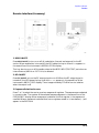
Rear Panel. . . . . . . . . . . . . . . . . . . . . . . . . . . . . . . . . . . . . . . . . . . . . . . . . . . . . . . . . . . . . . 1b-49
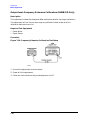
Remote Interface (Accessory). . . . . . . . . . . . . . . . . . . . . . . . . . . . . . . . . . . . . . . . . . . . . . . 1b-51
Memory Interface (Accessory) . . . . . . . . . . . . . . . . . . . . . . . . . . . . . . . . . . . . . . . . . . . . . . 1b-53
1c. Operation messages
Front Panel Operation Messages . . . . . . . . . . . . . . . . . . . . . . . . . . . . . . . . . . . . . . . . . . . . . . 1c-2
GPIB Command Messages . . . . . . . . . . . . . . . . . . . . . . . . . . . . . . . . . . . . . . . . . . . . . . . . . . . 1c-5
GPIB Execution Errors . . . . . . . . . . . . . . . . . . . . . . . . . . . . . . . . . . . . . . . . . . . . . . . . . . . . . . 1c-8
GPIB Device-Specific Errors . . . . . . . . . . . . . . . . . . . . . . . . . . . . . . . . . . . . . . . . . . . . . . . . . . 1c-9
GPIB Query Errors . . . . . . . . . . . . . . . . . . . . . . . . . . . . . . . . . . . . . . . . . . . . . . . . . . . . . . . . 1c-10
Service Messages . . . . . . . . . . . . . . . . . . . . . . . . . . . . . . . . . . . . . . . . . . . . . . . . . . . . . . . . . . 1c-11
2. GPIB Programming
Background . . . . . . . . . . . . . . . . . . . . . . . . . . . . . . . . . . . . . . . . . . . . . . . . . . . . . . . . . . . . . . . . 2-1
Programming Guidelines . . . . . . . . . . . . . . . . . . . . . . . . . . . . . . . . . . . . . . . . . . . . . . . . . . . . . 2-2
GPIB Definition . . . . . . . . . . . . . . . . . . . . . . . . . . . . . . . . . . . . . . . . . . . . . . . . . . . . . . . . . . . 2-2
What is Programmable . . . . . . . . . . . . . . . . . . . . . . . . . . . . . . . . . . . . . . . . . . . . . . . . . . . . . 2-2
GPIB Address . . . . . . . . . . . . . . . . . . . . . . . . . . . . . . . . . . . . . . . . . . . . . . . . . . . . . . . . . . . . . 2-2
Error Messages. . . . . . . . . . . . . . . . . . . . . . . . . . . . . . . . . . . . . . . . . . . . . . . . . . . . . . . . . . . . 2-2
Programming Language . . . . . . . . . . . . . . . . . . . . . . . . . . . . . . . . . . . . . . . . . . . . . . . . . . . . 2-2
Query. . . . . . . . . . . . . . . . . . . . . . . . . . . . . . . . . . . . . . . . . . . . . . . . . . . . . . . . . . . . . . . . . . . . 2-2
Advanced Programming. . . . . . . . . . . . . . . . . . . . . . . . . . . . . . . . . . . . . . . . . . . . . . . . . . . . . 2-2
Programming Examples . . . . . . . . . . . . . . . . . . . . . . . . . . . . . . . . . . . . . . . . . . . . . . . . . . . . . . 2-3
Programming RF Frequency . . . . . . . . . . . . . . . . . . . . . . . . . . . . . . . . . . . . . . . . . . . . . . . . . 2-3
Programming RF Frequency and FM Modulation . . . . . . . . . . . . . . . . . . . . . . . . . . . . . . . . 2-3
Querying RF Frequency. . . . . . . . . . . . . . . . . . . . . . . . . . . . . . . . . . . . . . . . . . . . . . . . . . . . . 2-4
Programming RF Amplitude . . . . . . . . . . . . . . . . . . . . . . . . . . . . . . . . . . . . . . . . . . . . . . . . . 2-4
Programming Pulse Modulation (Option 1E6) . . . . . . . . . . . . . . . . . . . . . . . . . . . . . . . . . . . 2-4
Programming Pager Encoder (Option 1EP) . . . . . . . . . . . . . . . . . . . . . . . . . . . . . . . . . . . . . 2-5
x
Contents
GPIB Status Reporing . . . . . . . . . . . . . . . . . . . . . . . . . . . . . . . . . . . . . . . . . . . . . . . . . . . . . . .2-12
External Modulation Input Level Status. . . . . . . . . . . . . . . . . . . . . . . . . . . . . . . . . . . . . . .2-14
Reverse Power Protection Status . . . . . . . . . . . . . . . . . . . . . . . . . . . . . . . . . . . . . . . . . . . . .2-16
Unspecified Power (Amplitude) Entry Status . . . . . . . . . . . . . . . . . . . . . . . . . . . . . . . . . . .2-17
Pager Encoding Status (Option 1EP Only) . . . . . . . . . . . . . . . . . . . . . . . . . . . . . . . . . . . . .2-18
SCPI Command Reference. . . . . . . . . . . . . . . . . . . . . . . . . . . . . . . . . . . . . . . . . . . . . . . . . . . .2-20
ABORt Subsystem (Option 1EP Only). . . . . . . . . . . . . . . . . . . . . . . . . . . . . . . . . . . . . . . . .2-21
AM Subsystem. . . . . . . . . . . . . . . . . . . . . . . . . . . . . . . . . . . . . . . . . . . . . . . . . . . . . . . . . . . .2-21
CAL Subsystem . . . . . . . . . . . . . . . . . . . . . . . . . . . . . . . . . . . . . . . . . . . . . . . . . . . . . . . . . . .2-22
DM Subsystem (Option 1EP Only) . . . . . . . . . . . . . . . . . . . . . . . . . . . . . . . . . . . . . . . . . . .2-22
FM Subsystem. . . . . . . . . . . . . . . . . . . . . . . . . . . . . . . . . . . . . . . . . . . . . . . . . . . . . . . . . . . .2-23
FREQuency Subsystem . . . . . . . . . . . . . . . . . . . . . . . . . . . . . . . . . . . . . . . . . . . . . . . . . . . .2-24
INITiate Subsystem (Option 1EP Only) . . . . . . . . . . . . . . . . . . . . . . . . . . . . . . . . . . . . . . .2-24
OUTPut Subsystem . . . . . . . . . . . . . . . . . . . . . . . . . . . . . . . . . . . . . . . . . . . . . . . . . . . . . . .2-24
PAGing Subsystem (Option 1EP Only) . . . . . . . . . . . . . . . . . . . . . . . . . . . . . . . . . . . . . . . .2-25
PM Subsystem. . . . . . . . . . . . . . . . . . . . . . . . . . . . . . . . . . . . . . . . . . . . . . . . . . . . . . . . . . . .2-37
POWer Subsystem. . . . . . . . . . . . . . . . . . . . . . . . . . . . . . . . . . . . . . . . . . . . . . . . . . . . . . . . .2-38
PULM Subsystem . . . . . . . . . . . . . . . . . . . . . . . . . . . . . . . . . . . . . . . . . . . . . . . . . . . . . . . . .2-38
STATus Subsystem . . . . . . . . . . . . . . . . . . . . . . . . . . . . . . . . . . . . . . . . . . . . . . . . . . . . . . . .2-39
SYSTem Subsystem . . . . . . . . . . . . . . . . . . . . . . . . . . . . . . . . . . . . . . . . . . . . . . . . . . . . . . .2-40
TRIGger Subsystem (Option 1EP Only) . . . . . . . . . . . . . . . . . . . . . . . . . . . . . . . . . . . . . . .2-40
Changing Parameters While Encoding (Option 1EP Only) . . . . . . . . . . . . . . . . . . . . . . . . . .2-41
Using the Buffer Memory for the Arbitrary Messages. . . . . . . . . . . . . . . . . . . . . . . . . . . . . .2-41
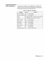
GPIB Capabilities. . . . . . . . . . . . . . . . . . . . . . . . . . . . . . . . . . . . . . . . . . . . . . . . . . . . . . . . . . .2-43
GPIB Connector Information. . . . . . . . . . . . . . . . . . . . . . . . . . . . . . . . . . . . . . . . . . . . . . . . . .2-44
8656/57 Compatible Language . . . . . . . . . . . . . . . . . . . . . . . . . . . . . . . . . . . . . . . . . . . . . . . .2-45
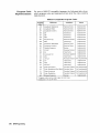
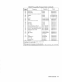
Program Code Implementation . . . . . . . . . . . . . . . . . . . . . . . . . . . . . . . . . . . . . . . . . . . . . .2-46
Receiving the Clear Message . . . . . . . . . . . . . . . . . . . . . . . . . . . . . . . . . . . . . . . . . . . . . . . .2-48
Additional Programming Information . . . . . . . . . . . . . . . . . . . . . . . . . . . . . . . . . . . . . . . . .2-48
3. Installation
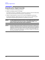
Unpacking Your Signal Generator . . . . . . . . . . . . . . . . . . . . . . . . . . . . . . . . . . . . . . . . . . . . . .3-2
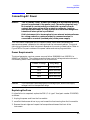
Connecting AC Power. . . . . . . . . . . . . . . . . . . . . . . . . . . . . . . . . . . . . . . . . . . . . . . . . . . . . . . . .3-3
Power Requirements . . . . . . . . . . . . . . . . . . . . . . . . . . . . . . . . . . . . . . . . . . . . . . . . . . . . . . . .3-3
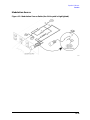
Replacing the Fuse . . . . . . . . . . . . . . . . . . . . . . . . . . . . . . . . . . . . . . . . . . . . . . . . . . . . . . . . .3-3
Turning On the Signal Generator . . . . . . . . . . . . . . . . . . . . . . . . . . . . . . . . . . . . . . . . . . . . . . .3-6
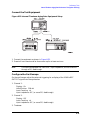
Connecting to Other Instruments . . . . . . . . . . . . . . . . . . . . . . . . . . . . . . . . . . . . . . . . . . . . . . .3-7
Storing the Signal Generator. . . . . . . . . . . . . . . . . . . . . . . . . . . . . . . . . . . . . . . . . . . . . . . . . . .3-8
Shipping the Signal Generator . . . . . . . . . . . . . . . . . . . . . . . . . . . . . . . . . . . . . . . . . . . . . . . . .3-9
4. Specifications
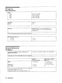
Options . . . . . . . . . . . . . . . . . . . . . . . . . . . . . . . . . . . . . . . . . . . . . . . . . . . . . . . . . . . . . . . . . . . .4-1
Option Specifications . . . . . . . . . . . . . . . . . . . . . . . . . . . . . . . . . . . . . . . . . . . . . . . . . . . . . . .4-1
Frequency Specifications . . . . . . . . . . . . . . . . . . . . . . . . . . . . . . . . . . . . . . . . . . . . . . . . . . . . . .4-2
Internal Reference Oscillator . . . . . . . . . . . . . . . . . . . . . . . . . . . . . . . . . . . . . . . . . . . . . . . . . .4-2
Output. . . . . . . . . . . . . . . . . . . . . . . . . . . . . . . . . . . . . . . . . . . . . . . . . . . . . . . . . . . . . . . . . . . . .4-3
Spectral Purity . . . . . . . . . . . . . . . . . . . . . . . . . . . . . . . . . . . . . . . . . . . . . . . . . . . . . . . . . . . . . .4-4
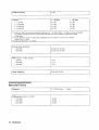
Frequency Modulation . . . . . . . . . . . . . . . . . . . . . . . . . . . . . . . . . . . . . . . . . . . . . . . . . . . . . . . .4-5
xi
Contents
Phase Modulation . . . . . . . . . . . . . . . . . . . . . . . . . . . . . . . . . . . . . . . . . . . . . . . . . . . . . . . . . . . 4-6
Amplitude Modulation . . . . . . . . . . . . . . . . . . . . . . . . . . . . . . . . . . . . . . . . . . . . . . . . . . . . . . . 4-7
Modulation Source. . . . . . . . . . . . . . . . . . . . . . . . . . . . . . . . . . . . . . . . . . . . . . . . . . . . . . . . . . . 4-8
Remote Programming . . . . . . . . . . . . . . . . . . . . . . . . . . . . . . . . . . . . . . . . . . . . . . . . . . . . . . . . 4-8
Environmental . . . . . . . . . . . . . . . . . . . . . . . . . . . . . . . . . . . . . . . . . . . . . . . . . . . . . . . . . . . . . . 4-9
General. . . . . . . . . . . . . . . . . . . . . . . . . . . . . . . . . . . . . . . . . . . . . . . . . . . . . . . . . . . . . . . . . . . . 4-9
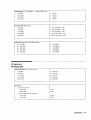
Modulation Generator Option 1E2 . . . . . . . . . . . . . . . . . . . . . . . . . . . . . . . . . . . . . . . . . . . . . 4-10
Pulse Modulation Option 1E6. . . . . . . . . . . . . . . . . . . . . . . . . . . . . . . . . . . . . . . . . . . . . . . . . 4-11
Pager Encoder/Signalling Option 1EP . . . . . . . . . . . . . . . . . . . . . . . . . . . . . . . . . . . . . . . . . . 4-11
Frequency Modulation. . . . . . . . . . . . . . . . . . . . . . . . . . . . . . . . . . . . . . . . . . . . . . . . . . . . . 4-12
Paging Signaling . . . . . . . . . . . . . . . . . . . . . . . . . . . . . . . . . . . . . . . . . . . . . . . . . . . . . . . . . 4-12
Modulation Source. . . . . . . . . . . . . . . . . . . . . . . . . . . . . . . . . . . . . . . . . . . . . . . . . . . . . . . . 4-12
General . . . . . . . . . . . . . . . . . . . . . . . . . . . . . . . . . . . . . . . . . . . . . . . . . . . . . . . . . . . . . . . . . 4-12
Regulatory Information. . . . . . . . . . . . . . . . . . . . . . . . . . . . . . . . . . . . . . . . . . . . . . . . . . . . . . 4-13
ISO 9002 Compliant . . . . . . . . . . . . . . . . . . . . . . . . . . . . . . . . . . . . . . . . . . . . . . . . . . . . . . 4-13
Statement of Compliance . . . . . . . . . . . . . . . . . . . . . . . . . . . . . . . . . . . . . . . . . . . . . . . . . . 4-13
Noise Declaration . . . . . . . . . . . . . . . . . . . . . . . . . . . . . . . . . . . . . . . . . . . . . . . . . . . . . . . . . 4-13
5.Service
Shipping Your Instrument Back to Agilent Technologies . . . . . . . . . . . . . . . . . . . . . . . . . . . . 5-2
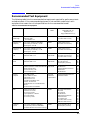
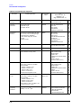
Recommended Test Equipment . . . . . . . . . . . . . . . . . . . . . . . . . . . . . . . . . . . . . . . . . . . . . . . . 5-3
Post-Repair. . . . . . . . . . . . . . . . . . . . . . . . . . . . . . . . . . . . . . . . . . . . . . . . . . . . . . . . . . . . . . . . . 5-6
Safety Notes . . . . . . . . . . . . . . . . . . . . . . . . . . . . . . . . . . . . . . . . . . . . . . . . . . . . . . . . . . . . . . . . 5-9
5a. Theory of Operation
Overview . . . . . . . . . . . . . . . . . . . . . . . . . . . . . . . . . . . . . . . . . . . . . . . . . . . . . . . . . . . . . . . . . 5a-4
A1 Front Panel. . . . . . . . . . . . . . . . . . . . . . . . . . . . . . . . . . . . . . . . . . . . . . . . . . . . . . . . . . . . . 5a-5
A2 Power Supply . . . . . . . . . . . . . . . . . . . . . . . . . . . . . . . . . . . . . . . . . . . . . . . . . . . . . . . . . . . 5a-7
A3 Motherboard . . . . . . . . . . . . . . . . . . . . . . . . . . . . . . . . . . . . . . . . . . . . . . . . . . . . . . . . . . . . 5a-8
A4 Reference . . . . . . . . . . . . . . . . . . . . . . . . . . . . . . . . . . . . . . . . . . . . . . . . . . . . . . . . . . . . . . 5a-9
A5 Sig Gen Synth . . . . . . . . . . . . . . . . . . . . . . . . . . . . . . . . . . . . . . . . . . . . . . . . . . . . . . . . . 5a-10
A6 Output (8648A). . . . . . . . . . . . . . . . . . . . . . . . . . . . . . . . . . . . . . . . . . . . . . . . . . . . . . . . . 5a-11
A6 Output (8648B/C/D) . . . . . . . . . . . . . . . . . . . . . . . . . . . . . . . . . . . . . . . . . . . . . . . . . . . . . 5a-12
A7 Attenuator (8648A) . . . . . . . . . . . . . . . . . . . . . . . . . . . . . . . . . . . . . . . . . . . . . . . . . . . . . 5a-13
A10 Frequency Extension (8648B/C/D) . . . . . . . . . . . . . . . . . . . . . . . . . . . . . . . . . . . . . . . . 5a-14
A11 Attenuator (8648B/C/D). . . . . . . . . . . . . . . . . . . . . . . . . . . . . . . . . . . . . . . . . . . . . . . . . 5a-15
A12 Reverse Power Protection(8648B/C/D) . . . . . . . . . . . . . . . . . . . . . . . . . . . . . . . . . . . . . 5a-16
A13 Pulse Modulator (8648B/C/D Option 1E6) . . . . . . . . . . . . . . . . . . . . . . . . . . . . . . . . . . 5a-17
A14 Modulation Generator (Option 1E2) . . . . . . . . . . . . . . . . . . . . . . . . . . . . . . . . . . . . . . . 5a-18
A30 Pager Encoder (8648A Option 1EP) . . . . . . . . . . . . . . . . . . . . . . . . . . . . . . . . . . . . . . . 5a-19
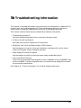
5b. Troubleshooting Information
Troubleshooting Checklist . . . . . . . . . . . . . . . . . . . . . . . . . . . . . . . . . . . . . . . . . . . . . . . . . . . 5b-2
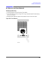
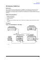
AC Mains (Line) Fuse Removal . . . . . . . . . . . . . . . . . . . . . . . . . . . . . . . . . . . . . . . . . . . . . . . 5b-3
To Remove the Fuse . . . . . . . . . . . . . . . . . . . . . . . . . . . . . . . . . . . . . . . . . . . . . . . . . . . . . . . 5b-3
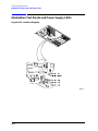
Modulation Test Points and Power Supply LEDs . . . . . . . . . . . . . . . . . . . . . . . . . . . . . . . . . 5b-4
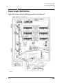
Power Supply Distribution . . . . . . . . . . . . . . . . . . . . . . . . . . . . . . . . . . . . . . . . . . . . . . . . . . . 5b-5
xii
Contents
5c. Service Error Messages
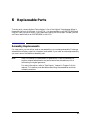
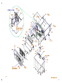
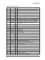
6. Replaceable Parts
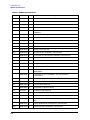
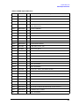
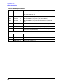
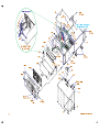
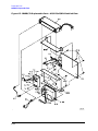
Assembly Replacements. . . . . . . . . . . . . . . . . . . . . . . . . . . . . . . . . . . . . . . . . . . . . . . . . . . . . . .6-1
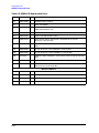
8648A Replaceable Parts . . . . . . . . . . . . . . . . . . . . . . . . . . . . . . . . . . . . . . . . . . . . . . . . . . . . . .6-3
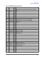
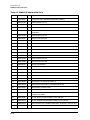
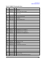
8648B/C/D Replaceable Parts . . . . . . . . . . . . . . . . . . . . . . . . . . . . . . . . . . . . . . . . . . . . . . . . . .6-9
7. Adjustments
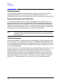
Test Equipment . . . . . . . . . . . . . . . . . . . . . . . . . . . . . . . . . . . . . . . . . . . . . . . . . . . . . . . . . . . . .7-2
Equipment Setup for Automated Tests . . . . . . . . . . . . . . . . . . . . . . . . . . . . . . . . . . . . . . . . .7-2
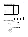
Test Point Extender . . . . . . . . . . . . . . . . . . . . . . . . . . . . . . . . . . . . . . . . . . . . . . . . . . . . . . . .7-2
Manual Adjustments . . . . . . . . . . . . . . . . . . . . . . . . . . . . . . . . . . . . . . . . . . . . . . . . . . . . . . . . .7-4
Internal Reference Oscillator Adjustment. . . . . . . . . . . . . . . . . . . . . . . . . . . . . . . . . . . . . . .7-5
Pager Encoder Timebase Frequency Adjustment . . . . . . . . . . . . . . . . . . . . . . . . . . . . . . . . .7-7
Automated Adjustments . . . . . . . . . . . . . . . . . . . . . . . . . . . . . . . . . . . . . . . . . . . . . . . . . . . . .7-9
AM Level and Distortion (8648A Only) . . . . . . . . . . . . . . . . . . . . . . . . . . . . . . . . . . . . . . . .7-10
AM Level (8648B/C/D Only) . . . . . . . . . . . . . . . . . . . . . . . . . . . . . . . . . . . . . . . . . . . . . . . . .7-12
Detector Offset (8648A Only) . . . . . . . . . . . . . . . . . . . . . . . . . . . . . . . . . . . . . . . . . . . . . . . .7-14
Output Level (8648A Only) . . . . . . . . . . . . . . . . . . . . . . . . . . . . . . . . . . . . . . . . . . . . . . . . .7-15
AM Level: FE (8648B/C/D Only) . . . . . . . . . . . . . . . . . . . . . . . . . . . . . . . . . . . . . . . . . . . . .7-16
Predistortion and Detector Offset (8648B/C/D Only) . . . . . . . . . . . . . . . . . . . . . . . . . . . . .7-18
Prelevel (8648B/C/D Only) . . . . . . . . . . . . . . . . . . . . . . . . . . . . . . . . . . . . . . . . . . . . . . . . . .7-19
Output level: Frequency Extension Calibration (8648B/C/D Only) . . . . . . . . . . . . . . . . . .7-20
AM Modulator (8648A Only) . . . . . . . . . . . . . . . . . . . . . . . . . . . . . . . . . . . . . . . . . . . . . . . .7-21
Time Base DAC (All 8648A/B/C/D) . . . . . . . . . . . . . . . . . . . . . . . . . . . . . . . . . . . . . . . . . . .7-23
Motherboard Audio Path (All 8648A/B/C/D) . . . . . . . . . . . . . . . . . . . . . . . . . . . . . . . . . . . .7-24
DCFM (All 8648A/B/C/D) . . . . . . . . . . . . . . . . . . . . . . . . . . . . . . . . . . . . . . . . . . . . . . . . . . .7-26
Audio Generator (Options 1E2 and 1EP Only) . . . . . . . . . . . . . . . . . . . . . . . . . . . . . . . . . .7-27
HF Power Level Accuracy (All 8648A/B/C/D) . . . . . . . . . . . . . . . . . . . . . . . . . . . . . . . . . . .7-28
LF Output Level (Most 8648B/C/D) . . . . . . . . . . . . . . . . . . . . . . . . . . . . . . . . . . . . . . . . . . .7-31
LF Power Level Accuracy (Most 8648B/C/D). . . . . . . . . . . . . . . . . . . . . . . . . . . . . . . . . . . .7-32
FSK Deviation (Option 1EP Only) . . . . . . . . . . . . . . . . . . . . . . . . . . . . . . . . . . . . . . . . . . . .7-34
Filter Path (Option 1EP Only) . . . . . . . . . . . . . . . . . . . . . . . . . . . . . . . . . . . . . . . . . . . . . . .7-35
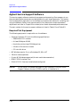
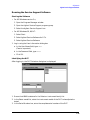
Agilent Service Support Software . . . . . . . . . . . . . . . . . . . . . . . . . . . . . . . . . . . . . . . . . . . . . .7-36
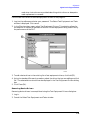
Required Test Equipment. . . . . . . . . . . . . . . . . . . . . . . . . . . . . . . . . . . . . . . . . . . . . . . . . . .7-36
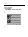
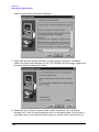
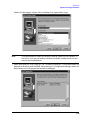
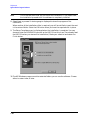
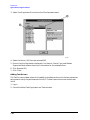
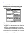
Installing the Software . . . . . . . . . . . . . . . . . . . . . . . . . . . . . . . . . . . . . . . . . . . . . . . . . . . . .7-37
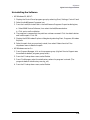
Uninstalling the Software . . . . . . . . . . . . . . . . . . . . . . . . . . . . . . . . . . . . . . . . . . . . . . . . . .7-41
Service Support Software Administration. . . . . . . . . . . . . . . . . . . . . . . . . . . . . . . . . . . . . .7-42
Running the Service Support Software . . . . . . . . . . . . . . . . . . . . . . . . . . . . . . . . . . . . . . . .7-53
Motherboard Repair Utility . . . . . . . . . . . . . . . . . . . . . . . . . . . . . . . . . . . . . . . . . . . . . . . . .7-58
8. Performance Tests
Calibration Cycle . . . . . . . . . . . . . . . . . . . . . . . . . . . . . . . . . . . . . . . . . . . . . . . . . . . . . . . . . . . .8-2
Required Test Equipment . . . . . . . . . . . . . . . . . . . . . . . . . . . . . . . . . . . . . . . . . . . . . . . . . . . . .8-3
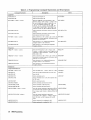
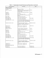
Performance Test Descriptions . . . . . . . . . . . . . . . . . . . . . . . . . . . . . . . . . . . . . . . . . . . . . . . . .8-6
Manual Performance Tests . . . . . . . . . . . . . . . . . . . . . . . . . . . . . . . . . . . . . . . . . . . . . . . . . . .8-6
Automated Performance Tests . . . . . . . . . . . . . . . . . . . . . . . . . . . . . . . . . . . . . . . . . . . . . . . .8-6
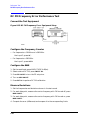
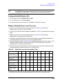
FM Accuracy Performance Test. . . . . . . . . . . . . . . . . . . . . . . . . . . . . . . . . . . . . . . . . . . . . . . . .8-7
xiii
Contents
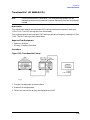
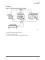
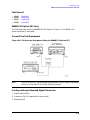
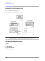
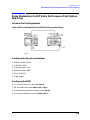
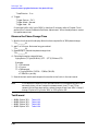
Connect the Test Equipment . . . . . . . . . . . . . . . . . . . . . . . . . . . . . . . . . . . . . . . . . . . . . . . . . 8-7
Configure the Measuring Receiver . . . . . . . . . . . . . . . . . . . . . . . . . . . . . . . . . . . . . . . . . . . . 8-7
Configure the 8648 . . . . . . . . . . . . . . . . . . . . . . . . . . . . . . . . . . . . . . . . . . . . . . . . . . . . . . . . . 8-7
Measure Deviations . . . . . . . . . . . . . . . . . . . . . . . . . . . . . . . . . . . . . . . . . . . . . . . . . . . . . . . . 8-7
Test Record . . . . . . . . . . . . . . . . . . . . . . . . . . . . . . . . . . . . . . . . . . . . . . . . . . . . . . . . . . . . . . . 8-7
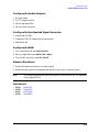
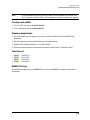
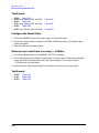
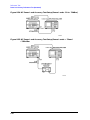
8648B/C/D Only . . . . . . . . . . . . . . . . . . . . . . . . . . . . . . . . . . . . . . . . . . . . . . . . . . . . . . . . . . . 8-8
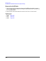
Connect the Test Equipment . . . . . . . . . . . . . . . . . . . . . . . . . . . . . . . . . . . . . . . . . . . . . . . . . 8-8
Configure the Synthesized Signal Generator . . . . . . . . . . . . . . . . . . . . . . . . . . . . . . . . . . . . 8-8
Measure Deviations . . . . . . . . . . . . . . . . . . . . . . . . . . . . . . . . . . . . . . . . . . . . . . . . . . . . . . . . 8-8
Test Record . . . . . . . . . . . . . . . . . . . . . . . . . . . . . . . . . . . . . . . . . . . . . . . . . . . . . . . . . . . . . . . 8-9
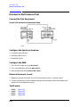
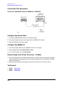
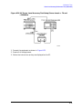
FM Accuracy Performance Test (Option 1E2 Only). . . . . . . . . . . . . . . . . . . . . . . . . . . . . . . . 8-10
Connect the Test Equipment . . . . . . . . . . . . . . . . . . . . . . . . . . . . . . . . . . . . . . . . . . . . . . . . 8-10
Configure the Measuring Receiver . . . . . . . . . . . . . . . . . . . . . . . . . . . . . . . . . . . . . . . . . . . 8-10
Configure the 8648 . . . . . . . . . . . . . . . . . . . . . . . . . . . . . . . . . . . . . . . . . . . . . . . . . . . . . . . . 8-10
Measure Deviations . . . . . . . . . . . . . . . . . . . . . . . . . . . . . . . . . . . . . . . . . . . . . . . . . . . . . . . 8-10
Test Record . . . . . . . . . . . . . . . . . . . . . . . . . . . . . . . . . . . . . . . . . . . . . . . . . . . . . . . . . . . . . . 8-11
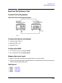
8648B/C/D Option 1E2 Only . . . . . . . . . . . . . . . . . . . . . . . . . . . . . . . . . . . . . . . . . . . . . . . . 8-11
Connect the Test Equipment . . . . . . . . . . . . . . . . . . . . . . . . . . . . . . . . . . . . . . . . . . . . . . . . 8-11
Configure the Synthesized Signal Generator . . . . . . . . . . . . . . . . . . . . . . . . . . . . . . . . . . . 8-11
Measure Deviations . . . . . . . . . . . . . . . . . . . . . . . . . . . . . . . . . . . . . . . . . . . . . . . . . . . . . . . 8-12
Test Record . . . . . . . . . . . . . . . . . . . . . . . . . . . . . . . . . . . . . . . . . . . . . . . . . . . . . . . . . . . . . . 8-12
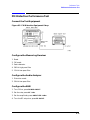
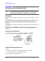
FM Distortion Performance Test . . . . . . . . . . . . . . . . . . . . . . . . . . . . . . . . . . . . . . . . . . . . . . 8-13
Connect the Test Equipment . . . . . . . . . . . . . . . . . . . . . . . . . . . . . . . . . . . . . . . . . . . . . . . . 8-13
Configure the Measuring Receiver . . . . . . . . . . . . . . . . . . . . . . . . . . . . . . . . . . . . . . . . . . . 8-13
Configure the Audio Analyzer . . . . . . . . . . . . . . . . . . . . . . . . . . . . . . . . . . . . . . . . . . . . . . . 8-13
Configure the 8648 . . . . . . . . . . . . . . . . . . . . . . . . . . . . . . . . . . . . . . . . . . . . . . . . . . . . . . . . 8-13
Measure Distortion. . . . . . . . . . . . . . . . . . . . . . . . . . . . . . . . . . . . . . . . . . . . . . . . . . . . . . . . 8-14
Test Record . . . . . . . . . . . . . . . . . . . . . . . . . . . . . . . . . . . . . . . . . . . . . . . . . . . . . . . . . . . . . . 8-14
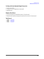
8648B/C/D Only . . . . . . . . . . . . . . . . . . . . . . . . . . . . . . . . . . . . . . . . . . . . . . . . . . . . . . . . . . 8-14
Connect the Test Equipment . . . . . . . . . . . . . . . . . . . . . . . . . . . . . . . . . . . . . . . . . . . . . . . . 8-14
Configure the Synthesized Signal Generator . . . . . . . . . . . . . . . . . . . . . . . . . . . . . . . . . . . 8-15
Measure Deviations . . . . . . . . . . . . . . . . . . . . . . . . . . . . . . . . . . . . . . . . . . . . . . . . . . . . . . . 8-15
Test Record . . . . . . . . . . . . . . . . . . . . . . . . . . . . . . . . . . . . . . . . . . . . . . . . . . . . . . . . . . . . . . 8-15
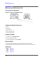
AM Accuracy Performance Test . . . . . . . . . . . . . . . . . . . . . . . . . . . . . . . . . . . . . . . . . . . . . . . 8-16
Connect the Test Equipment . . . . . . . . . . . . . . . . . . . . . . . . . . . . . . . . . . . . . . . . . . . . . . . . 8-16
Configure the Measuring Receiver . . . . . . . . . . . . . . . . . . . . . . . . . . . . . . . . . . . . . . . . . . . 8-16
Configure the 8648 . . . . . . . . . . . . . . . . . . . . . . . . . . . . . . . . . . . . . . . . . . . . . . . . . . . . . . . . 8-16
Measure Depths . . . . . . . . . . . . . . . . . . . . . . . . . . . . . . . . . . . . . . . . . . . . . . . . . . . . . . . . . . 8-16
Test Record . . . . . . . . . . . . . . . . . . . . . . . . . . . . . . . . . . . . . . . . . . . . . . . . . . . . . . . . . . . . . . 8-16
AM Accuracy Performance Test (Option 1E2 Only) . . . . . . . . . . . . . . . . . . . . . . . . . . . . . . . 8-17
Connect the Test Equipment . . . . . . . . . . . . . . . . . . . . . . . . . . . . . . . . . . . . . . . . . . . . . . . . 8-17
Configure the Measuring Receiver . . . . . . . . . . . . . . . . . . . . . . . . . . . . . . . . . . . . . . . . . . . 8-17
Configure the 8648 . . . . . . . . . . . . . . . . . . . . . . . . . . . . . . . . . . . . . . . . . . . . . . . . . . . . . . . . 8-17
Measure Depths . . . . . . . . . . . . . . . . . . . . . . . . . . . . . . . . . . . . . . . . . . . . . . . . . . . . . . . . . . 8-17
Test Record . . . . . . . . . . . . . . . . . . . . . . . . . . . . . . . . . . . . . . . . . . . . . . . . . . . . . . . . . . . . . . 8-18
AM Distortion Performance Test . . . . . . . . . . . . . . . . . . . . . . . . . . . . . . . . . . . . . . . . . . . . . . 8-19
Connect the Test Equipment . . . . . . . . . . . . . . . . . . . . . . . . . . . . . . . . . . . . . . . . . . . . . . . . 8-19
Configure the Measuring Receiver . . . . . . . . . . . . . . . . . . . . . . . . . . . . . . . . . . . . . . . . . . . 8-19
Configure the Audio Analyzer . . . . . . . . . . . . . . . . . . . . . . . . . . . . . . . . . . . . . . . . . . . . . . . 8-19
xiv
Contents
Configure the 8648 . . . . . . . . . . . . . . . . . . . . . . . . . . . . . . . . . . . . . . . . . . . . . . . . . . . . . . . .8-19
Measure Distortion Amplitudes . . . . . . . . . . . . . . . . . . . . . . . . . . . . . . . . . . . . . . . . . . . . . .8-20
Test Record . . . . . . . . . . . . . . . . . . . . . . . . . . . . . . . . . . . . . . . . . . . . . . . . . . . . . . . . . . . . . .8-20
Phase Modulation Distortion Performance Test. . . . . . . . . . . . . . . . . . . . . . . . . . . . . . . . . . .8-21
Connect the Test Equipment . . . . . . . . . . . . . . . . . . . . . . . . . . . . . . . . . . . . . . . . . . . . . . . .8-21
Configure the Measuring Receiver. . . . . . . . . . . . . . . . . . . . . . . . . . . . . . . . . . . . . . . . . . . .8-21
Configure the Audio Analyzer . . . . . . . . . . . . . . . . . . . . . . . . . . . . . . . . . . . . . . . . . . . . . . .8-21
Configure the 8648 . . . . . . . . . . . . . . . . . . . . . . . . . . . . . . . . . . . . . . . . . . . . . . . . . . . . . . . .8-21
Measure Distortion . . . . . . . . . . . . . . . . . . . . . . . . . . . . . . . . . . . . . . . . . . . . . . . . . . . . . . . .8-22
Test Record . . . . . . . . . . . . . . . . . . . . . . . . . . . . . . . . . . . . . . . . . . . . . . . . . . . . . . . . . . . . . .8-22
8648B/C/D Only. . . . . . . . . . . . . . . . . . . . . . . . . . . . . . . . . . . . . . . . . . . . . . . . . . . . . . . . . . .8-22
Connect the Test Equipment . . . . . . . . . . . . . . . . . . . . . . . . . . . . . . . . . . . . . . . . . . . . . . . .8-22
Configure the Synthesized Signal Generator . . . . . . . . . . . . . . . . . . . . . . . . . . . . . . . . . . .8-23
Measure Deviations . . . . . . . . . . . . . . . . . . . . . . . . . . . . . . . . . . . . . . . . . . . . . . . . . . . . . . .8-23
Test Record . . . . . . . . . . . . . . . . . . . . . . . . . . . . . . . . . . . . . . . . . . . . . . . . . . . . . . . . . . . . . .8-23
Residual FM Performance Test . . . . . . . . . . . . . . . . . . . . . . . . . . . . . . . . . . . . . . . . . . . . . . . .8-24
Connect the Test Equipment . . . . . . . . . . . . . . . . . . . . . . . . . . . . . . . . . . . . . . . . . . . . . . . .8-24
Configure the Measuring Receiver. . . . . . . . . . . . . . . . . . . . . . . . . . . . . . . . . . . . . . . . . . . .8-24
Configure the Audio Analyzer . . . . . . . . . . . . . . . . . . . . . . . . . . . . . . . . . . . . . . . . . . . . . . .8-25
Configure the Synthesized Signal Generator . . . . . . . . . . . . . . . . . . . . . . . . . . . . . . . . . . .8-25
Configure the 8648 . . . . . . . . . . . . . . . . . . . . . . . . . . . . . . . . . . . . . . . . . . . . . . . . . . . . . . . .8-25
Measure Deviations . . . . . . . . . . . . . . . . . . . . . . . . . . . . . . . . . . . . . . . . . . . . . . . . . . . . . . .8-25
Test Record . . . . . . . . . . . . . . . . . . . . . . . . . . . . . . . . . . . . . . . . . . . . . . . . . . . . . . . . . . . . . .8-25
Harmonics Performance Test. . . . . . . . . . . . . . . . . . . . . . . . . . . . . . . . . . . . . . . . . . . . . . . . . .8-26
Connect the Test Equipment . . . . . . . . . . . . . . . . . . . . . . . . . . . . . . . . . . . . . . . . . . . . . . . .8-26
Configure the Spectrum Analyzer . . . . . . . . . . . . . . . . . . . . . . . . . . . . . . . . . . . . . . . . . . . .8-26
Configure the 8648 . . . . . . . . . . . . . . . . . . . . . . . . . . . . . . . . . . . . . . . . . . . . . . . . . . . . . . . .8-26
Measure Harmonic Levels . . . . . . . . . . . . . . . . . . . . . . . . . . . . . . . . . . . . . . . . . . . . . . . . . .8-26
Test Record . . . . . . . . . . . . . . . . . . . . . . . . . . . . . . . . . . . . . . . . . . . . . . . . . . . . . . . . . . . . . .8-26
Spurious Performance Test . . . . . . . . . . . . . . . . . . . . . . . . . . . . . . . . . . . . . . . . . . . . . . . . . . .8-27
Connect the Test Equipment . . . . . . . . . . . . . . . . . . . . . . . . . . . . . . . . . . . . . . . . . . . . . . . .8-27
Configure the Spectrum Analyzer . . . . . . . . . . . . . . . . . . . . . . . . . . . . . . . . . . . . . . . . . . . .8-27
Configure the 8648 . . . . . . . . . . . . . . . . . . . . . . . . . . . . . . . . . . . . . . . . . . . . . . . . . . . . . . . .8-27
Measure Spurious Levels . . . . . . . . . . . . . . . . . . . . . . . . . . . . . . . . . . . . . . . . . . . . . . . . . . .8-27
Test Record . . . . . . . . . . . . . . . . . . . . . . . . . . . . . . . . . . . . . . . . . . . . . . . . . . . . . . . . . . . . . .8-27
DC FM Frequency Error Performance Test . . . . . . . . . . . . . . . . . . . . . . . . . . . . . . . . . . . . . .8-28
Connect the Test Equipment . . . . . . . . . . . . . . . . . . . . . . . . . . . . . . . . . . . . . . . . . . . . . . . .8-28
Configure the Frequency Counter . . . . . . . . . . . . . . . . . . . . . . . . . . . . . . . . . . . . . . . . . . . .8-28
Configure the 8648 . . . . . . . . . . . . . . . . . . . . . . . . . . . . . . . . . . . . . . . . . . . . . . . . . . . . . . . .8-28
Measure Deviations . . . . . . . . . . . . . . . . . . . . . . . . . . . . . . . . . . . . . . . . . . . . . . . . . . . . . . .8-28
Test Record . . . . . . . . . . . . . . . . . . . . . . . . . . . . . . . . . . . . . . . . . . . . . . . . . . . . . . . . . . . . . .8-29
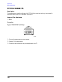
RF level Accuracy Performance Test. . . . . . . . . . . . . . . . . . . . . . . . . . . . . . . . . . . . . . . . . . . .8-30
Description . . . . . . . . . . . . . . . . . . . . . . . . . . . . . . . . . . . . . . . . . . . . . . . . . . . . . . . . . . . . . .8-30
Connect the Test Equipment . . . . . . . . . . . . . . . . . . . . . . . . . . . . . . . . . . . . . . . . . . . . . . . .8-30
Configure the Measuring Receiver. . . . . . . . . . . . . . . . . . . . . . . . . . . . . . . . . . . . . . . . . . . .8-30
Configure the 8648 . . . . . . . . . . . . . . . . . . . . . . . . . . . . . . . . . . . . . . . . . . . . . . . . . . . . . . . .8-31
Measure Amplitudes . . . . . . . . . . . . . . . . . . . . . . . . . . . . . . . . . . . . . . . . . . . . . . . . . . . . . . .8-31
Test Record . . . . . . . . . . . . . . . . . . . . . . . . . . . . . . . . . . . . . . . . . . . . . . . . . . . . . . . . . . . . . .8-31
8648B/C/D Only. . . . . . . . . . . . . . . . . . . . . . . . . . . . . . . . . . . . . . . . . . . . . . . . . . . . . . . . . . .8-31
xv
Contents
Connect the Test Equipment . . . . . . . . . . . . . . . . . . . . . . . . . . . . . . . . . . . . . . . . . . . . . . . . 8-32
Configure the Power Meter . . . . . . . . . . . . . . . . . . . . . . . . . . . . . . . . . . . . . . . . . . . . . . . . . 8-32
Configure the 8648B/C/D . . . . . . . . . . . . . . . . . . . . . . . . . . . . . . . . . . . . . . . . . . . . . . . . . . . 8-32
Measure High Level Power Accuracy (≤ 13 dBm). . . . . . . . . . . . . . . . . . . . . . . . . . . . . . . . 8-32
Test Record . . . . . . . . . . . . . . . . . . . . . . . . . . . . . . . . . . . . . . . . . . . . . . . . . . . . . . . . . . . . . . 8-32
Configure the 8648 Option 1EA . . . . . . . . . . . . . . . . . . . . . . . . . . . . . . . . . . . . . . . . . . . . . 8-33
Measure the High Power Level Accuracy . . . . . . . . . . . . . . . . . . . . . . . . . . . . . . . . . . . . . . 8-33
Test Record . . . . . . . . . . . . . . . . . . . . . . . . . . . . . . . . . . . . . . . . . . . . . . . . . . . . . . . . . . . . . . 8-34
Configure the Power Meter . . . . . . . . . . . . . . . . . . . . . . . . . . . . . . . . . . . . . . . . . . . . . . . . . 8-34
Measure Low Level Power accuracy (< −20 dBm) . . . . . . . . . . . . . . . . . . . . . . . . . . . . . . . 8-34
Test Record . . . . . . . . . . . . . . . . . . . . . . . . . . . . . . . . . . . . . . . . . . . . . . . . . . . . . . . . . . . . . . 8-34
Pulse Modulation On/Off Ratio Performance Test (Option 1E6 Only) . . . . . . . . . . . . . . . . . 8-35
Connect the Test Equipment . . . . . . . . . . . . . . . . . . . . . . . . . . . . . . . . . . . . . . . . . . . . . . . . 8-35
Configure the Spectrum Analyzer . . . . . . . . . . . . . . . . . . . . . . . . . . . . . . . . . . . . . . . . . . . . 8-35
Configure the 8648 . . . . . . . . . . . . . . . . . . . . . . . . . . . . . . . . . . . . . . . . . . . . . . . . . . . . . . . . 8-35
Measure the On/Off Ratio . . . . . . . . . . . . . . . . . . . . . . . . . . . . . . . . . . . . . . . . . . . . . . . . . . 8-36
Test Record . . . . . . . . . . . . . . . . . . . . . . . . . . . . . . . . . . . . . . . . . . . . . . . . . . . . . . . . . . . . . . 8-36
Pulse Modulation Rise Time Performance Test (Option 1E6 Only) . . . . . . . . . . . . . . . . . . . 8-37
Connect the Test Equipment . . . . . . . . . . . . . . . . . . . . . . . . . . . . . . . . . . . . . . . . . . . . . . . . 8-37
Configure the Pulse Generator . . . . . . . . . . . . . . . . . . . . . . . . . . . . . . . . . . . . . . . . . . . . . . 8-37
Configure the 8648 . . . . . . . . . . . . . . . . . . . . . . . . . . . . . . . . . . . . . . . . . . . . . . . . . . . . . . . . 8-37
Configure the Oscilloscope . . . . . . . . . . . . . . . . . . . . . . . . . . . . . . . . . . . . . . . . . . . . . . . . . . 8-37
Measure the Rise Time . . . . . . . . . . . . . . . . . . . . . . . . . . . . . . . . . . . . . . . . . . . . . . . . . . . . 8-38
Test Record . . . . . . . . . . . . . . . . . . . . . . . . . . . . . . . . . . . . . . . . . . . . . . . . . . . . . . . . . . . . . . 8-38
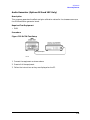
Pager Encoder Timebase Accuracy Performance Test (Option 1EP Only). . . . . . . . . . . . . . 8-39
Connect the Test Equipment . . . . . . . . . . . . . . . . . . . . . . . . . . . . . . . . . . . . . . . . . . . . . . . . 8-39
Configure the Frequency Counter . . . . . . . . . . . . . . . . . . . . . . . . . . . . . . . . . . . . . . . . . . . . 8-39
Configure the 8648 . . . . . . . . . . . . . . . . . . . . . . . . . . . . . . . . . . . . . . . . . . . . . . . . . . . . . . . . 8-39
Measure the Frequency . . . . . . . . . . . . . . . . . . . . . . . . . . . . . . . . . . . . . . . . . . . . . . . . . . . . 8-39
Test Record . . . . . . . . . . . . . . . . . . . . . . . . . . . . . . . . . . . . . . . . . . . . . . . . . . . . . . . . . . . . . . 8-39
FSK Deviation Accuracy Performance Test (Option 1EP Only) . . . . . . . . . . . . . . . . . . . . . . 8-40
Connect the Test Equipment . . . . . . . . . . . . . . . . . . . . . . . . . . . . . . . . . . . . . . . . . . . . . . . . 8-40
Configure the Vector Signal Analyzer . . . . . . . . . . . . . . . . . . . . . . . . . . . . . . . . . . . . . . . . . 8-40
Configure the 8648 . . . . . . . . . . . . . . . . . . . . . . . . . . . . . . . . . . . . . . . . . . . . . . . . . . . . . . . . 8-42
Measure FSK Deviation. . . . . . . . . . . . . . . . . . . . . . . . . . . . . . . . . . . . . . . . . . . . . . . . . . . . 8-43
Test Record . . . . . . . . . . . . . . . . . . . . . . . . . . . . . . . . . . . . . . . . . . . . . . . . . . . . . . . . . . . . . . 8-45
Internal Timebase: Aging Rate Performance Test (Option 1E5 Only) . . . . . . . . . . . . . . . . . 8-46
Description . . . . . . . . . . . . . . . . . . . . . . . . . . . . . . . . . . . . . . . . . . . . . . . . . . . . . . . . . . . . . . 8-46
Connect the Test Equipment . . . . . . . . . . . . . . . . . . . . . . . . . . . . . . . . . . . . . . . . . . . . . . . . 8-47
Configure the Oscilloscope . . . . . . . . . . . . . . . . . . . . . . . . . . . . . . . . . . . . . . . . . . . . . . . . . . 8-47
Measure the Phase Change Time . . . . . . . . . . . . . . . . . . . . . . . . . . . . . . . . . . . . . . . . . . . . 8-48
Test Record . . . . . . . . . . . . . . . . . . . . . . . . . . . . . . . . . . . . . . . . . . . . . . . . . . . . . . . . . . . . . . 8-48
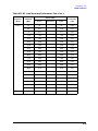
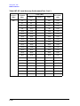
Power Level Accuracy Performance Test (Automated) . . . . . . . . . . . . . . . . . . . . . . . . . . . . . 8-49
Description . . . . . . . . . . . . . . . . . . . . . . . . . . . . . . . . . . . . . . . . . . . . . . . . . . . . . . . . . . . . . . 8-49
Required Test Equipment . . . . . . . . . . . . . . . . . . . . . . . . . . . . . . . . . . . . . . . . . . . . . . . . . . 8-49
Procedure . . . . . . . . . . . . . . . . . . . . . . . . . . . . . . . . . . . . . . . . . . . . . . . . . . . . . . . . . . . . . . . 8-49
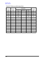
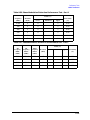
8648A Test Record . . . . . . . . . . . . . . . . . . . . . . . . . . . . . . . . . . . . . . . . . . . . . . . . . . . . . . . . . . 8-52
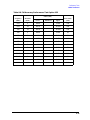
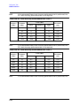
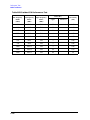
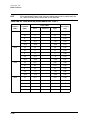
8648B Test Record . . . . . . . . . . . . . . . . . . . . . . . . . . . . . . . . . . . . . . . . . . . . . . . . . . . . . . . . . . 8-72
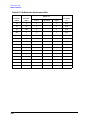
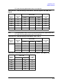
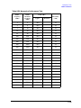
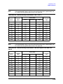
8648C Test Record . . . . . . . . . . . . . . . . . . . . . . . . . . . . . . . . . . . . . . . . . . . . . . . . . . . . . . . . . . 8-96
xvi
Contents
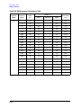
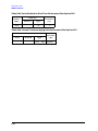
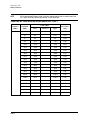
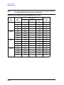
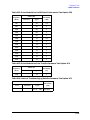
8648D Test Record . . . . . . . . . . . . . . . . . . . . . . . . . . . . . . . . . . . . . . . . . . . . . . . . . . . . . . . . .8-122
9. Supplemental Verification Tests
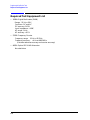
Required Test Equipment List . . . . . . . . . . . . . . . . . . . . . . . . . . . . . . . . . . . . . . . . . . . . . . . . .9-2
CW Frequency Accuracy Supplemental Verification Test . . . . . . . . . . . . . . . . . . . . . . . . . . . .9-3
Connect the Test Equipment . . . . . . . . . . . . . . . . . . . . . . . . . . . . . . . . . . . . . . . . . . . . . . . . .9-3
Configure the Frequency Counter . . . . . . . . . . . . . . . . . . . . . . . . . . . . . . . . . . . . . . . . . . . . .9-3
Configure the 8648 . . . . . . . . . . . . . . . . . . . . . . . . . . . . . . . . . . . . . . . . . . . . . . . . . . . . . . . . .9-3
Measure Frequency Accuracy. . . . . . . . . . . . . . . . . . . . . . . . . . . . . . . . . . . . . . . . . . . . . . . . .9-3
Test Record . . . . . . . . . . . . . . . . . . . . . . . . . . . . . . . . . . . . . . . . . . . . . . . . . . . . . . . . . . . . . . .9-4
9 kHz RF Level Accuracy Supplemental Verification Test . . . . . . . . . . . . . . . . . . . . . . . . . . .9-8
Connect the Test Equipment . . . . . . . . . . . . . . . . . . . . . . . . . . . . . . . . . . . . . . . . . . . . . . . . .9-8
Configure the Multimeter (DMM) . . . . . . . . . . . . . . . . . . . . . . . . . . . . . . . . . . . . . . . . . . . . .9-8
Configure the 8648 . . . . . . . . . . . . . . . . . . . . . . . . . . . . . . . . . . . . . . . . . . . . . . . . . . . . . . . . .9-8
Measure RF levels. . . . . . . . . . . . . . . . . . . . . . . . . . . . . . . . . . . . . . . . . . . . . . . . . . . . . . . . . .9-8
Test Record . . . . . . . . . . . . . . . . . . . . . . . . . . . . . . . . . . . . . . . . . . . . . . . . . . . . . . . . . . . . . . .9-9
xvii
Contents
xviii
1 Operation
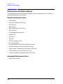
“Operation” contains the following information:
• 1. Operation: Provides a quick overview of the instrument’s operation.
• 1a. Operation Examples: provides examples to help you learn how to operate the
instrument.
• 1b. Operation reference: Provides quick access to information about each of the
instrument’s functions.
• 1c. Operation Messages: Provides information about both front panel and GPIB remote
operation messages.
NOTE
For Information about service messages numbered 500 and above, refer to
Chapter 5c, “Service Error Messages”.
1-1
Operation
Quick Overview
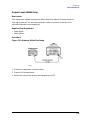
Quick Overview
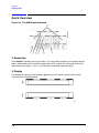
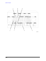
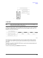
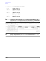
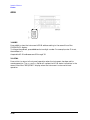
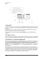
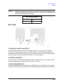
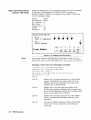
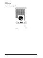
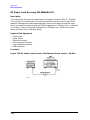
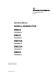
Figure 1-1. The 8648 Signal Generator
1. Power Key
Press POWER to power up the instrument. The instrument powers up to the same state it
was in when power was turned off, except that the RF output will be turned off and the
digit-select arrow keys (⇐ and ⇒) will be reset to the least significant digit.
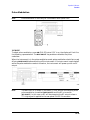
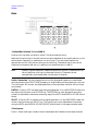
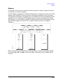
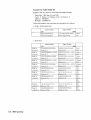
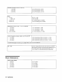
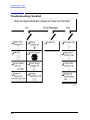
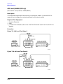
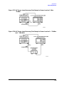
2. Display
The display can be one of two displays depending on the serial number prefix of your
instrument as illustrated below.
1-2
Operation
Quick Overview
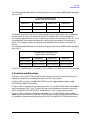
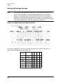
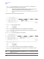
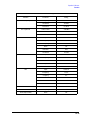
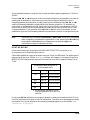
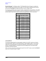
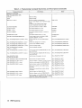
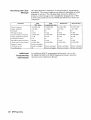
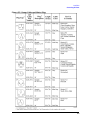
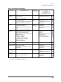
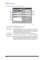
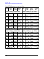
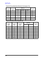
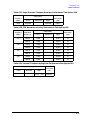
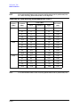
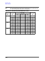
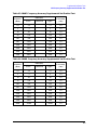
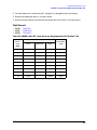
The following table describes the prefixes that apply to the various 8648 models equipped
with an LCD.
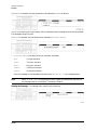
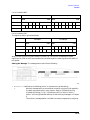
A. Liquid Crystal Display (LCD)
(labels located above the display)
8648A Prefix
8648B Prefix
8648C Prefix
8648D Prefix
3636A and below
3623A and below
3623A and below
3613A and below
3643U and below
3642U and below
3642u and below
3642U and below
The display contrast of the LCD can be achieved using the adjustment that is located on
the rear panel of these instruments. Note that this adjustment is only available for
instruments equipped with an LCD. It allows you to adjust the contrast of the LCD. Turn
the adjustment to optimize the display for viewing from most angles. If the display is
blank, first attempt to adjust the display contrast before returning the instrument for
service.
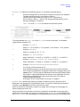
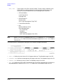
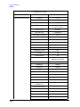
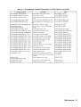
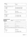
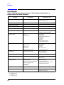
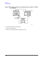
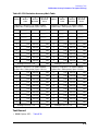
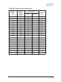
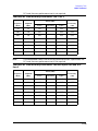
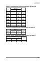
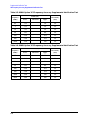
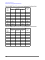
The following table describes the prefixes that apply to the various 8648 models equipped
with a VFD.
A. Vacuum Fluorescent Display (VCD)
(labels located below the display)
8648A Prefix
8648B Prefix
8648C Prefix
8648D Prefix
3636A and above
3623A and above
3623A and above
3613A and above
3643U and above
3642U and above
3642u and above
3642U and above
The VFD is a 2x40 display. The intensity of this display is at 100% and cannot be adjusted.
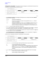
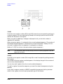
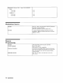
3. Function and Data Keys
The keys in the FUNCTION and DATA blocks allow you to enter values for setting the
frequency, amplitude, and modulation level of the RF output signal.
If Option 1EP is present, the FM (ENCODER) key will toggle between pager encoder
(ENCODER) mode and FM mode.
If Option 1EP is present and the signal generator is in the ENCODER mode, the rad dBµV
key functions as a SHIFT key. This key lets you input alphabetical characters using the
DATA and MODULATION SOURCE blocks when you are in pager encoder mode.
If Option 1EP is present and the signal generator is in the ENCODER mode, the MHz
dB(m) key functions as an ENTER key. The ENTER key must be used to store any numeric
or alphabetic characters entered by way of the DATA and MODULATION source blocks.
1-3
Operation
Quick Overview
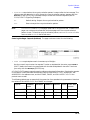
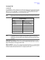
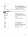
4. Increment Set Keys
When you press a FUNCTION key, that function becomes the active function. Press INCR
SET to view or change the increment value for the active function. Press ⇑ or ⇓ at any time
to change the active function setting by the increment value. (If Option 1EP is present and
the signal generator is in the ENCODER mode, these keys have alternate functions.)
If Option 1EP is present and the signal generator is in the ENCODER mode, the INCR SET
key functions as a START/STOP key. This key starts or stops any pager encoding activity.
In addition, in this mode, the ⇑ and ⇓ function as PREV and NEXT keys. These keys let
you move the blinking cursor between each parameter when you are entering the pager
encoding settings.
5. Knobs
The knobs are always active when the instrument is in local (front panel) control. Turn
them to increase or decrease the frequency or the amplitude of the RF output. Press ⇐ or
⇒, next to each knob, to adjust the knobs resolution.
Press REF SET, next to each knob, to set the displayed value as the reference value and
turn on the reference mode. Press REF ON/OFF to turn on and off the reference mode
without changing the reference value. When the reference mode is on, the displayed value
indicates the offset between the reference value and the RF output signal.
If Option 1EP is present and the signal generator is in the ENCODER mode, the
AMPLITUDE/ENCODER knob is used to enter a setting for a pager encoding parameter.
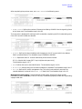
6. MEMORY
memory registers allow you to save instrument setups and recall them whenever you wish.
Press SAV and enter a two-digit register number to save the instrument’s current settings.
To recall the settings, press REG and enter the register number. The arrow keys allow you
to recall registers in numerical sequence. You can arrange your registers in up to ten
different sequences.
The number of the currently selected sequence and the last register selected are always
displayed in the lower-left corner of the display to help you keep track of where you are in
your testing process. (If Option 1EP is present, the sequence and register are not displayed
on any pager encoding menu.) The memory register examples provided in Chapter 1a,
“Operation Examples,” show you how to create a sequence and how to delete or add
registers in your sequence.
1-4
Operation
Quick Overview
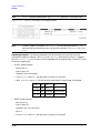
7. Modulation Source
Press MOD ON/OFF to turn on or off the modulation source. Press INT 400 kHz or INT 1 kHz to
select one of the internal source tones for modulating the RF output signal. These tones
are also available as an output signal at the MOD INPUT/OUTPUT port when they are
selected. Press EXT AC or EXT DC to ac- or dc-couple an external audio source via the MOD
INPUT/OUTPUT port.
Press 1kHz + EXT DC to frequency modulate the RF signal with the internal 1 kHz tone and
an external source at the same time. (Additional internal plus external modulation
capabilities are available for GPIB operation.) 1kHz + EXT DC will also amplitude or phase
modulate the RF signal with the internal 1 kHz tone but it will not be dc-coupled.
If Option 1EP is present, the INT 1kHz (FREQUENCY) key, or if Option 1E2 is present, the
INT 1kHz (FREQUENCY/WAVEFORM) key scrolls between five states: a fixed 1 kHz
internal source and a variable-frequency internal source with four different waveform
selections. The four modulation waveforms are sine, triangle, square, and sawtooth (or
ramp).
1-5
Operation
Quick Overview
1-6
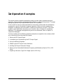
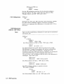
1a Operation Examples
This section contains operating examples to help you learn how to operate the signal
generator. These examples can be performed without any additional equipment. The pager
testing example can only be performed if Option 1EP is present.
If this is the first time you have operated this instrument, perform each of the following
examples for a quick introduction to general operation. After you have completed the
examples, try operating the instrument’s remaining functions on your own. If you have
trouble or want additional information on a function, refer to Chapter 1b, “Operation
Reference.” If a message is displayed that you do not understand, refer to Chapter 1c,
“Operation Messages.”
The item numbers of the following operation examples correspond to the numbers called
out on drawing of the instrument front panel.
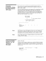
1. Setting the RF Output Signal
2. Incrementing or Decrementing the RF Output Signal
3. Using the Memory Registers
4. Offsetting the RF Output from a Reference
5. Holding the Output Attenuator Range
6. Setting a User Selectable Modulated Frequency and Waveform (Option 1E2 or 1EP
Only)
7. Signaling a Numeric-Type FLEX Pager (Option 1EP Only)
1a-1
Operation Examples
1a-2
Operation Examples
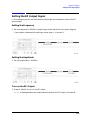
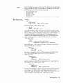
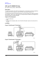
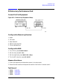
Setting the RF Output Signal
Setting the RF Output Signal
In this example, you will set the frequency, amplitude, and modulation level of the RF
output signal.
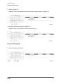
Setting the Frequency
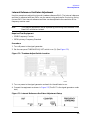
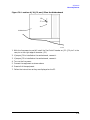
1. Set the frequency to 100 MHz using the keys shown below the instrument diagram.
If you make a mistake while entering a value, press ⇐ to correct it.
Setting the Amplitude
2. Set the amplitude to −100 dBm.
Turn on the RF Output
3. Press RF ON/OFF to turn on the RF output.
RF OFF is displayed below the amplitude setting when the RF output is turned off.
1a-3
Operation Examples
Setting the RF Output Signal
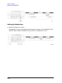
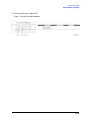
Setting the Modulation
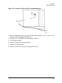
4. Set the FM deviation to 3 kHz.
The modulation rate is displayed below the deviation setting. Use the MODULATION
SOURCE keys to select a modulation source and turn modulation on or off.
1a-4
Operation Examples
Incrementing or Decrementing the RF output Signal
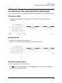
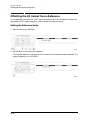
Incrementing or Decrementing the RF output Signal
In this example, you will increment the amplitude and frequency of the RF output signal.
Preliminary Steps
1. If they are not already set, set the frequency to 100 MHz and the amplitude to
−100 dBm.
Using the Knob
2. Increment the amplitude using the knob.
Press ⇐ or ⇒ when you wish to adjust the increment resolution.
Using the Increment Keys
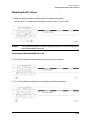
3. Enter a frequency increment of 25 kHz
The
symbol is displayed when you press INCR SET to indicate that the displayed
value is the increment set value.
1a-5
Operation Examples
Incrementing or Decrementing the RF output Signal
4. Increment the Rf output frequency in 25 kHz steps.
The increment keys affect the last FUNCTION selected (FREQUENCY, AMPLITUDE,
FM, AM, OR φM).
1a-6
Operation Examples
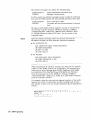
Using the Memory Registers
Using the Memory Registers
The memory register examples show you how to crate a sequence of registers, delete a
register from that sequence, renumber the registers in the sequence, and insert a new
register in the sequence.
Up to 10 register sequences can be defined (0 through 9). A sequence can contain up to 100
registers (00 through 99). There are a total of 300 registers available in the instrument.
The registers can be used in the sequences in any combination 9such as 10 sequences of 30
registers each, or 3 sequences of 100 registers each) as long as the total does not exceed
300 registers. It is not possible to have all 10 sequences each contain 100 registers as that
would be 1000 registers. (If Option 1EP is present, there are a total of 70 registers
available.)
1a-7
Operation Examples
Using the Memory Registers
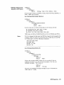
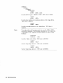
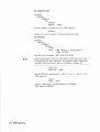
Saving Instrument Setting in Register Sequences
In this ten step example, you will use the memory keys to create a sequence containing
three registers. Each register will contain a different frequency setting.
Selecting the Sequence
1. Select sequence 0.
If there are registers saved in sequence 0, the message shown in the display below will
not appear. Note that the steps in this example will cause the settings in registers 00,
01, and 02 of sequence 0 to be changed.
Saving Settings in Registers
2. Set the frequency to 10 MHz.
3. Save the instrument settings in register 00.
1a-8
Operation Examples
Using the Memory Registers
4. Set the frequency setting to 11 MHz.
5. Save the instrument settings in register 01.
6. Set the frequency to 12 MHz.
7. Save the instrument settings in register 02.
1a-9
Operation Examples
Using the Memory Registers
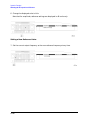
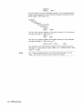
Checking the Sequence
8. Recall the registers in sequence 0.
The ⇑ and ⇓ keys recall registers or sequences depending on which key was pressed last
(REG or SEQ).
Checking a Different Sequence
9. Select sequence 1.
10.Step through the registers in sequence 1 if there are registers saved in it.
NOTE
1a-10
Sequence 1 does not contain the settings you saved in sequence 0. The
instrument enables you to save different settings in each sequence to create
up to ten different sequences for your testing. Remember when you save or
recall a register, be sure that the correct sequence is also selected.
Operation Examples
Using the Memory Registers
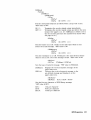
Deleting a Register from the Sequence
In this example, you will delete a register from the sequence you created in the preceding
example.
Selecting the Sequence
1. Select sequence 0.
Deleting a Register
2. Delete register 01 from sequence 0.
NOTE
The contents of the register are recalled when it is deleted. This allows you to
re-save the contents if you need to.
1a-11
Operation Examples
Using the Memory Registers
3. Step through the remaining registers in sequence 0.
The deleted register number has been removed from the sequence. Note that the
instrument does not renumber the registers when one is deleted.
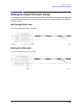
Renumbering the Registers in a Sequence
In this example, you will eliminate the skip from register 00 to register 02 in sequence 0
caused when you deleted register 01 in the previous example.
Decreasing the Register Number
1. Delete register 02.
The settings saved in register 02 are recalled when it is deleted.
2. Save the settings from register 02 into register 01.
1a-12
Operation Examples
Using the Memory Registers
Checking the Sequence
3. Step through the register sequence.
NOTE
In this example, you renumbered one register. when you need to renumber
two or more registers, use REG instead of DEL to recall each register until you
get to the last register in the sequence, then use DEL.
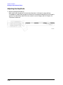
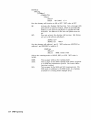
Inserting a Register in a Sequence
In this example, you will insert a register into the sequence you created in the previous
example. The process involves incrementing each register number that comes after the
point in the sequence where you wish to insert a register.
1. Recall the last register in sequence 0.
2. Save the recalled settings into register 02.
1a-13
Operation Examples
Using the Memory Registers
3. Recall register 00.
Register 01 can now be used to save the settings that are saved in register 00.
4. Save the recalled settings into register 01.
Register 00 can now be used to save the new settings.
Saving a New Register
5. Set the frequency to 8 MHz.
1a-14
Operation Examples
Using the Memory Registers
6. Save the settings in register 00.
Press ⇑ to check the new sequence.
1a-15
Operation Examples
Offsetting the RF Output from a Reference
Offsetting the RF Output from a Reference
In this example, you will enter an RF output frequency, set it as the reference value, and
then offset the RF output frequency 10 MHz below the reference value.
Setting the Reference Value
1. Set the frequency to 500 MHz.
2. Set 500 MHz as the reference frequency.
The ∆ symbol appears in the display to indicate that the reference mode is selected. The
output frequency is still 500 MHz.
1a-16
Operation Examples
Offsetting the RF Output from a Reference
Offsetting the RF Output
3. Offset the output frequency 10 MHz below the reference frequency.
You can enter in the offset value directly, or use the knob or ⇑ and ⇓ keys.
Atttention!
In the reference mode, the output frequency equals the reference frequency ±
the displayed offset frequency.
Turning the Reference Mode Off or On
4. Turn off the reference mode to display the actual output frequency.
5. Turn on the reference mode without changing the reference frequency.
1a-17
Operation Examples
Offsetting the RF Output from a Reference
6. Change the displayed units to kHz.
Note that for amplitude, reference settings are displayed in dB units only.
Setting a New Reference Value
7. Set the current output frequency as the new reference frequency at any time.
1a-18
Operation Examples
Holding the Output Attenuator Range
Holding the Output Attenuator Range
In this example, you will hold the output attenuator so it does not change ranges when you
change the amplitude setting. This will prevent attenuator range changes from affecting
the output signal.
Set the Amplitude Level
1. Set the amplitude level to −82 dBm.
Holding the Attenuator
2. Hold the attenuator at this setting.
1a-19
Operation Examples
Holding the Output Attenuator Range
Adjusting the Amplitude
3. Adjust the amplitude setting.
Now amplitude changes do not cause the attenuator to change its range setting.
Consequently, amplitude changes are limited to the range provided by the instrument’s
vernier. For information about the instrument’s vernier ranges, refer to Chapter 1b,
“Operation Reference.”
1a-20
Operation Examples
Setting a User Selectable Modulated Frequency and Waveform (Option 1E2 or 1EP Only)
Setting a User Selectable Modulated Frequency and
Waveform (Option 1E2 or 1EP Only)
NOTE
This modulation example can only be performed if Option 1E2 or 1EP is
present.
In this example, you will select the modulation level and the modulated frequency and
waveform of the RF signal output.
Setting the Modulation Level
1. Select FM modulation with a deviation of 25 kHz.
Either AM or ΦM modulation may be used instead of FM. The modulation type (FM, AM,
or ΦM) and the modulation level (deviation or depth) is displayed on the top line of the
front panel display as shown.
Setting the Modulated Waveform
2. Press the INT 1kHz (FREQUENCY/WAVEFORM) key until SQU is selected.
Repetitively pressing the INT 1kHz (FREQUENCY/WAVEFORM) key selects one of five
states:
• a fixed 1 kHz sinewave internal source
• a variable-frequency sinewave source (indicated by SIN preceded by the frequency
value)
• a variable-frequency triangle source (TRI)
• a variable-frequency squarewave source (SQU)
• a variable-frequency sawtooth (or ramp) source (SAW)
1a-21
Operation Examples
Setting a User Selectable Modulated Frequency and Waveform (Option 1E2 or 1EP Only)
Setting the Modulated Frequency
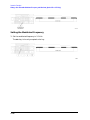
3. Set the modulated frequency to 1.5 kHz.
The kHz key is the only accepted units key.
1a-22
Operation Examples
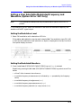
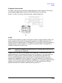
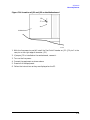
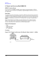
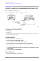
Signaling a Numeric-Type FLEX Pager (Option 1EP Only)
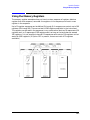
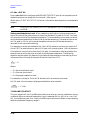
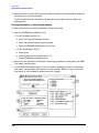
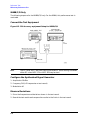
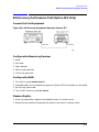
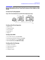
Signaling a Numeric-Type FLEX Pager (Option 1EP Only)
In this example you will set up the pager encoder to send a signal appropriate to test a
numeric-type FLEX pager.
NOTE
This pager encoding example can only be performed if Option 1EP is present.
The front panel of the Option 1EP instrument is different from the standard
instrument’s front panel. The green and blue labels are incorporated for the
pager encoding mode only. Therefore, these keys have multiple functions on
instruments with Option 1EP.
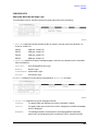
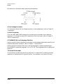
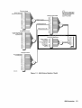
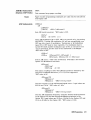
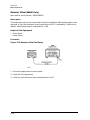
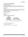
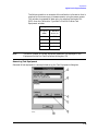
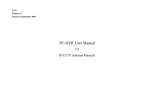
Figure 1a-1. The 8648A Option 1EP Signal Generator
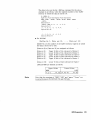
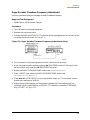
Setting Up Pager Encoding
The following steps are required to set up pager encoding on the signal generator. Details
of setting each parameter are provided following this overview.
1. Before entering the signal generator pager encoder mode, set the correct carrier
frequency and FM deviation for the pager-under-test. (The FM deviation is 4.8 kHz for
FLEX and is 4.5 kHz for POCSAG.)
2. Press RF ON/OFF to turn on the RF output. (RF OFF is displayed below the amplitude
setting when the RF output is turned off.)
3. Enter the pager encoder mode by pressing FM (ENCODER). If FM wasn’t the last
active function, press FM (ENCODER) twice.
4. Set up the pager encoder parameters to meet the test requirements of your specific
pager.
1a-23
Operation Examples
Signaling a Numeric-Type FLEX Pager (Option 1EP Only)
Use the ⇓ (NEXT) and ⇑ (PREV) keys to scroll through the encoder parameters. The
cursor will blink around the first letter of the active parameter. The ⇓ (NEXT) key
moves forward sequentially through each pager encoder parameter and the ⇑ (PREV)
key moves backward sequentially.
To move between setting for each parameter, rotate the AMPLITUDE/ENCODER knob
until the desired setting is displayed. When characters are entered by way of the
keypad (such as the capcode), terminate the entry with the MHz dB(m) (ENTER) key.
5. Start signaling the pager after all of the encoder parameters are set by pressing the
INCR SET (START/STOP) key.
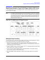
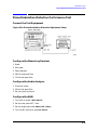
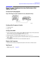
Entering Pager Encoding Settings
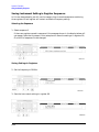
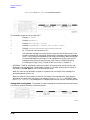
1. Display the first pager encoder menu.
After setting your pager’s carrier frequency and an FM deviation of 4.8 kHz (for a FLEX
pager) on the signal generator, press the FM (ENCODER) key once again to display the
first pager encoder menu (FORMAT). The FM (ENCODER) key toggles between the
frequency modulation menu and the pager encoder menu.
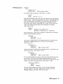
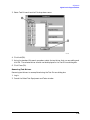
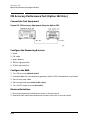
Selecting the Format Settings
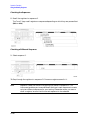
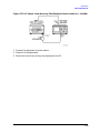
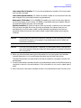
2. Set FORMAT to FLEX, POLARITY to NORMAL, and FILTER to ON.
a. With the blinking cursor on the “F” of FORMAT, set the FLEX format by rotating the
AMPLITUDE/ENCODER knob until FLEX is displayed.
b. Press the ⇓ (NEXT) key to move the blinking cursor to POLARITY, then use the
AMPLITUDE/ENCODER knob to set the polarity to NORMAL.
c. Using the ⇓ (NEXT) key and the AMPLITUDE/ENCODER knob, set FILTER to ON.
1a-24
Operation Examples
Signaling a Numeric-Type FLEX Pager (Option 1EP Only)
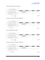
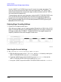
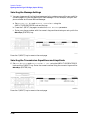
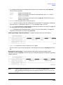
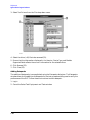
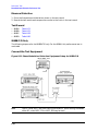
Selecting the Data Rate and Pager Type Settings
3. Set DATA RATE to 3200/2 and PAGER TYPE to NUMERIC, using the
AMPLITUDE/ENCODER knob and the ⇓ (NEXT) key.
You may choose to set the data rate to one of the other settings; you FLEX pager should
automatically adjust.
Press the ⇓ (NEXT) key to move to the next page.
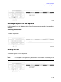
4. Set VECTOR TYPE to STANDARD using the AMPLITUDE/ENCODER knob.
Press the ⇓ (NEXT) key to move to the next page.
1a-25
Operation Examples
Signaling a Numeric-Type FLEX Pager (Option 1EP Only)
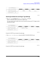
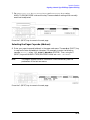
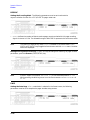
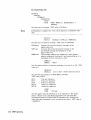
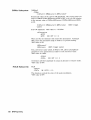
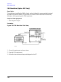
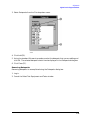
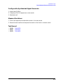
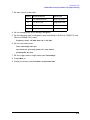
Selecting the Message Settings
5. You may choose one of the five fixed messages (only numbers one and five are useful for
numeric pagers) or you may define your own message. For this example, use your own
phone number as the user-defined message:
a. Set MESSAGE NO. to 6 and MESSAGE LENGTH to 40 using the
AMPLITUDE/ENCODER knob and the key.
b. Press the ⇓ (NEXT) key again to select the FREE MESSAGE parameter.
c. Enter your phone number with the numeric keys and terminate your entry with the
MHz dB(m) (ENTER) key.
Press the ⇓ (NEXT) key to move to the next page.
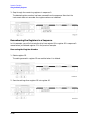
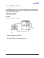
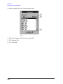
Selecting the Transmission Repetitions and Amplitude
6. Set MODE to SINGLE and AMPLITUDE to 0.0 dBm using the AMPLITUDE/ENCODER
knob and the ⇓ (NEXT) key. Enter the numeric values using the numeric keys and the
MHz dB(m) (ENTER) key.
Press the ⇓ (NEXT) key to move to the next page.
1a-26
Operation Examples
Signaling a Numeric-Type FLEX Pager (Option 1EP Only)
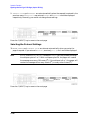
7. Set IMMEDIATE STOP to OFF, HEADER to ON, and TERMINATOR to ON using
AMPLITUDE/ENCODER knob and the key. These are default settings that normally
would not be adjusted.
Press the ⇓ (NEXT) key to move to the next page.
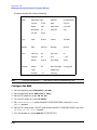
Selecting the Pager Capcode (Address)
8. Enter your pager’s capcode (address) in the pager code menu. The rad dBµV (SHIFT) key
is required to enter alphabetical characters. For example, to enter the following
capcode: A0012477, press, 7 (A), 0012477, MHz dB(m) (ENTER). Then, using the ⇓
(NEXT) key and the AMPLITUDE/ENCODER knob, set DUMMY CALL to OFF.
NOTE
The pager’s capcode contains information that automatically sets the
parameters of the last two menus.
Press the ⇓ (NEXT) key to move to the next page.
1a-27
Operation Examples
Signaling a Numeric-Type FLEX Pager (Option 1EP Only)
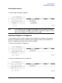
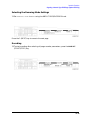
9. ADDRESS TYPE and ADDRESS1 are set automatically when the capcode is entered in the
previous menu. If A0012477 was entered, SHORT and 0045245 would be displayed
respectively. Generally, you would not change these settings.
Press the ⇓ (NEXT) key to move to the next page.
Selecting the Protocol Settings
10.FRAME, PHASE, and COLLAPSE CYCLE are also set automatically when you enter the
pager’s capcode. If you entered A0012477 previously, 011, D, and 4 would be displayed.
NOTE
If MODE is set to BURST or CONT instead of SINGLE, you may choose to change
the collapse cycle to 1 to 7. With a collapse cycle of 4, the pager will receive
the message once every 16 frames (24). If the collapse is 0 or 1, the pager will
receive the message either every frame (20), or every other frame (21).
Press the ⇓ (NEXT) key to move to the next page.
1a-28
Operation Examples
Signaling a Numeric-Type FLEX Pager (Option 1EP Only)
Selecting the Roaming Mode Settings
11.Set ROAMING MODE to NONE using the AMPLITUDE/ENCODER knob.
Press the ⇓ (NEXT) key to move to the next page.
Encoding
12.To start encoding after selecting all pager encoder parameters, press the INCR SET
(START/STOP) key.
1a-29
Operation Examples
Signaling a Numeric-Type FLEX Pager (Option 1EP Only)
1a-30
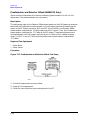
1b Operation Reference
This chapter describes each of the instrument’s functions including all of the front panel
keys, the rear panel connectors, and the optional remote interface and memory interface.
This information is presented in the same functional groups as the front panel key
functional groupings.
NOTE
Option 1EP adds a pager encoder capability to the standard functions.
Consequently the front panel of the Option 1EP instrument is different from
the standard instrument’s front panel. The green and blue labels are
incorporated for the pager encoding settings only. Therefore these keys have
multiple functions on instruments with Option 1EP.
1b-1
Operation Reference
Frequency and Amplitude
Frequency and Amplitude
The knob and reference set keys work similarly for both frequency and amplitude settings.
1. Knob
Turn the knobs to increment or decrement the frequency and amplitude settings. The
knobs are always active when the instrument is in local operation.
If Option 1EP is present and the signal generator is in the ENCODER mode, the knob in
the AMPLITUDE/ENCODER block is used to select the desired setting for each pager
encoder parameter.
2. Digit-Select Arrow Keys
Press these digit-select arrow keys (⇐ ⇒)to select the digit to be changed with the knob.
NOTE
The knobs increment the selected digit only. For information about
incrementing by an arbitrary value using the increment set keys, see
“Increment Set” in this chapter.
3. REF SET
Press REF SET to turn on the reference mode and to set the current RF output setting as
the reference value. The reference value is stored in non-volatile memory until you replace
it by pressing REF SET again.
When you press REF SET, the ∆ symbol is displayed between the value and the units. When
∆ appears, the displayed value indicates the offset between the reference value and the RF
output signal.
1b-2
Operation Reference
Frequency and Amplitude
The RF output signal is not changed when you press this key.
Units
When you press REF SET for frequency, values can be entered in MHz or kHz. For
amplitude, values can be entered in any of the amplitude units provided, but they are
displayed in dB only.
4. REF ON/OFF
Press REF ON/OFF to turn off the reference mode if it is on, or to turn on the reference mode
without changing the reference value.
When you turn on the reference mode, the displayed value indicates the offset between the
reference value and the current RF output setting.
The RF output signal is not changed when you press this key.
Output Power Trouble?
If the RF output power seems too low, look for ∆ in the display
between the power level value and the dB indicator. The ∆ tells
you that reference mode is turned on. The displayed value is not
the output power level; it is the offset between the reference value
and the output power. To exit the reference mode, press
REF ON/OFF. You can then reset the output power to the desired
level.
1b-3
Operation Reference
Function
Function
1. FREQUENCY
The RF output frequency range for each model is shown in the following table. When
making frequency changes, the instrument does not turn off the RF output. However, the
power does blank for a few milliseconds when crossing the frequencies at 249, 501, 1001,
1260, 1600, 2001, 2520, and 3200 MHz.
Model
Frequency Range
8648A
100 kHz to 1000 MHz
8648B
9 kHz to 2000 MHz
8648C
9 kHz to 3200 MHz
8648D
9 kHz to 4000 MHz
Frequency switching typically takes less than 75 ms at frequencies lower then 1001 MHz,
and less than 100 ms at higher frequencies.
1b-4
Operation Reference
Function
2. AMPLITUDE
The RF output amplitude range is shown in the following table. When making amplitude
changes, the instrument does not turn off the RF output. The period of any over- or
under-ranging that may occur during level transitions is typically less than 30 ms.
Output Amplitude Ranges
Model
Frequency Range
Amplitude
8648A
100 kHz to 1000 MHz
+10 to −136 dBm
8648B/C/D
≥ 2500 MHz
> 2500 MHz
+13 to −136 dBm
+10 to −136 dBm
8648B/C/D
with Option 1EA
< 100 kHz
≤ 1000 MHz
≤ 1500 MHz
≤ 2100 MHZ
≤ 2500 MHZ
> 2500 MHz
+17 to −136 dBm
+20 to −136 dBm
+19 to −136 dBm
+17 to −136 dBm
+15 to −136 dBm
+13 to −136 dBm
3. FM, AM, ΦM
Press FM to set the peak deviation for frequency modulation. Then use the data entry keys
to enter the desired value of deviation. The values allowed depend on the RF frequency
selected. See Chapter 4, "Specifications" for peak deviation specifications.
Press AM to set the amplitude modulation range. Then use the data entry keys to set the
desired value of range. Values from 0 through 100% are allowed.
Press FM to set the peak deviation for phase modulation. Then use the data entry keys to
enter the desired value of deviation. The values allowed depend on the RF frequency
selected. See Chapter 4, "Specifications" for peak deviation specifications.
1b-5
Operation Reference
Function
Setting Up the Pager Encoder
NOTE
The pager encoder mode is available only on instruments with Option 1EP.
Option 1EP adds pager encoding/signaling capabilities to the standard
functions. Consequently the front panel of the Option 1EP instrument is
different from the standard instrument’s front panel. The green and blue
labels are incorporated for the pager encoding settings only. Therefore, these
keys have multiple functions on instruments with Option 1EP.
Figure 1b-1. 8648A Option 1EP Signal Generator
For numeric messages, the following keys are assigned for the special characters in
addition to the standard numeric keys (0 to 9).
Front
Panel Key
1b-6
Character
B3
B2
B1
B0
S
Spare
1
0
1
0
U
U
1
0
1
1
Space
Space
1
1
0
0
-
- (Hyphen)
1
1
0
1
]
]
1
1
1
0
[
[
1
1
1
1
Operation Reference
Function
1. ENCODER
NOTE
Before selecting the pager encoder mode, check that the correct pager carrier
frequency and FM deviation have been set.
To select the pager encoder mode, press FM (ENCODER) twice: once to set FM deviation,
then again to toggle between the standard functions and the pager encoder mode. The
display will look like the following:
This format menu is always displayed first when the pager encoder mode is selected.
The ⇑ (PREV) and ⇓ (NEXT) keys are used to move the blinking cursor between each
parameter.
The knob in the AMPLITUDE/ENCODER block is used to select the desired setting for
each pager encoder parameter.
To start or stop encoding, press INCR SET (START/STOP).
1b-7
Operation Reference
Function
Setting the Format
The format menu, shown in the previous figure, has the following settings:
• FORMAT selects the pager protocol being tested.
FLEX:
FLEX format
FLEX-TD:
FLEX-TD format
POCSAG:
POCSAG format
PN15:
Pseudorandom Sequence (PN15)
RESYNC:
Re-synchronization function (for FLEX/FLEX-TD pagers only)
SERVICE:
Servicing the 8648A Option 1EP
• POLARITY selects the data polarity.
Normal:
Normal polarity
POCSAG
FLEX/FLEX-TD
(2-Level FSK),
RESYNC, PN15
FLEX/FLEX-TD
(4-Level FSK)
“1”: Carrier − Deviation
“1”: Carrier + Deviation
“10”: Carrier + Deviation
“11”: Carrier + (Deviation/3)
“01”: Carrier − (Deviation/3)
“0”: Carrier + Deviation
“0”: Carrier − Deviation
“00”: Carrier − Deviation
INVERSE:
Inverse polarity
POCSAG
FLEX/FLEX-TD
(2-Level FSK),
RESYNC, PN15
FLEX/FLEX-TD
(4-Level FSK)
“1”: Carrier + Deviation
“1”: Carrier − Deviation
“10”: Carrier − Deviation
“11”: Carrier − (Deviation/3)
“01”: Carrier + (Deviation/3)
“0”: Carrier − Deviation
“0”: Carrier + Deviation
“00”: Carrier + Deviation
• FILTER selects whether or not the baseband modulation filter (10th-order Bessel
low-pass filter, −3 dB at 3.9 kHz) is used. Normally the filter is on.
ON:
Uses the low-Pass filter
OFF:
Does not use the low-pass filter
1b-8
Operation Reference
Function
FLEX/FLEX-TD
Setting the data Rate and Pager Type
The parameter menu for the data rate and the pager type looks like the following:
• DATA RATE specifies how fast the data stream is output in bits per second and whether it is
2-level or 4-level FSK.
1600/2:
1600 bps, 2-level FSK
3200/2:
3200 bps, 2-level FSK
3200/4:
3200 bps, 4-level FSK
6400/4:
6400 bps, 4-level FSK
• PAGER TYPE specifies the type of message a pager under test can respond to and is selectable
from the following:
TONE ONLY:
Short Message/Tone only type
NUMERIC:
Numeric type
ALPHANUMERIC: Alphanumeric type
HEX/BIN:
HEX/Binary type
If NUMERIC is selected, the next setting to be selected is VECTOR TYPE as shown:
• VECTOR TYPE identifies the type of message as follows:
STANDARD:
The pager-under-test displays the numeric message it receives.
SPECIAL:
The pager-under-test converts the numeric message to a pre-defined message
which is displayed.
NUMBERED:
The message numbers are assigned for each paging address separately
starting at 0 and progressing up to a maximum of 63 in consecutive order.
1b-9
Operation Reference
Function
If NUMBERED is selected, the next parameter to be selected is NUMBER as follows.
NUMBER is for setting the initial number of the numbered numeric message that will be transmitted.
The allowable range is 0 to 63.
If HEX/BIN is selected, the next setting to be selected is BLOCKING LENGTH:
• BLOCKING LENGTH indicates the bits per character as follows:
1BIT:
1 bit per character
7BITS:
7 bits per character
8BITS:
8 bits per character
14BITS:
14 bits per character
16BITS:
16 bits per character
Enter the message in the hexadecimal format to the MESSAGE NO. 6 in the message menu.
NOTE
When 7BITS or 14BITS are selected, the total number of hexadecimal characters of
the message must be a multiple of 7 characters (28 bits).
Setting the Message The message menu looks like the following:
1b-10
Operation Reference
Function
• MESSAGE NO. is defined as the following where “X” represents the phase setting:
0:
Arbitrary message set from the external controller using the GPIB capability.
The data must be entered in units of works. Refer to
‘[SOURce]:PAGing[:FORMat]:{POCSag|FLEX|FTD}:ARBitrary:
DEFine <NR1>, <NR2>,..., <NR1>” and “Using the Buffer Memory for the
Arbitrary Messages” in Chapter 2.
START FRAME and STOP FRAME are defined in the following menu:
The frames between the START FRAME and STOP FRAME will be transmitted. The allowable
ranges for both are 000 to 127.
1:
Displays: 01223456[X}
where “X” = “0” for phase A, "1" for phase B, “2” for phase C, “3” for phase D.
2:
Displays: ABCDEFG[X}
where “X” = phase “A”, “B”, “C”, “D”.
3:
Displays: TEST PAGING:XXXXXXX
where “XXXXXXX” = “PHASE A”, “PHASE B”, “PHASE C”, or “PHASE D”.
4:
Displays: ALPHANUMERIC 40CHARS TEST PAGING:XXXXXXX
where “XXXXXXX” = “PHASE A”, “PHASE B”, “PHASE C”, or “PHASE D”.
5:
Displays: 8888888888888888888888888888888888888888
for LCD test with 50 characters of “8”
6:
User-definable message, up to 40 characters long, set from the front panel.
Enter numeric messages with the keypad. Alphanumeric messages require the
rad dBµV (SHIFT) key to access the alphabetical characters (blue letters) above
the keypad. If required alphabetical characters are not available on the front
panel, send a message from an external controller over GPIB. Refer to
“[SOURce]:Paging[:FORMat]
:{POCSag\FLEX|FTD}:MESS:DEFine ‘string’” in Chapter 2.
• MESSAGE LENGTH specifies the maximum number of characters that will be sent out and
displayed in the message field. The allowable range is 1 to 40. After specifying the number of
characters, press MHz dB(m) (ENTER) to save the new value.
When the value of this parameter is equal to or greater than the length of the message, the
whole message will be sent out.
When the value of this parameter is less than the length of the message, only the characters
specified by this parameter are output. (For example, if the MESSAGE NO. is 1 (0123456[X]) and
the MESSAGE LENGTH is 5, the message which is displayed and will be sent out is actually 01234.)
1b-11
Operation Reference
Function
Setting the Encoding Mode The number of times a message is transmitted and the level of that
transmission are determined by the following menu:
• MODE determines whether the message will be output once or multiple times when INCR SET
(START/STOP) is pressed.
SINGLE:
Outputs the message once.
BURST:
Outputs the message the number of times specified in the BURSTS field (3
times in this example).
CONT:
Outputs the message continuously until the INCR SET (START/STOP) key is
pressed a second time. (Note: The collapse cycle described later on in this
section will determine how often the message will be transmitted per cycle.)
• AMPLITUDE sets the output signal level of the carrier.
• BURSTS sets the number of times the message will be transmitted. This parameter is displayed
only when the MODE parameter is set to BURST. The allowable range is 1 to 256.
• RF OFF is displayed below the amplitude setting when the RF output is turned off. To toggle the
RF signal output on and off, press RF ON/OFF.
• HOLD is displayed when the step attenuator is held at its current range setting. To toggle the
attenuator hold function on and off, press ATTN HOLD.
Another menu is displayed as follows for completing the Encoding Mode:
• IMMEDIATE STOP terminates pager signaling as follows when a stop event occurs.
ON:
Terminates pager signaling immediately.
OFF:
Default setting. Terminates pager signaling just before the next instance the
pager is on. (If TERMINATOR is set to ON, the pager encoder generates the
re-synchronization pattern in the frame that was supposed to contain the
message.)
• HEADER sets whether the idle frame signal is output in the frame before the first message.
ON:
Default setting. Outputs the idle frame signal.
OFF:
Does not output the idle frame signal.
1b-12
Operation Reference
Function
• TERMINATOR sets whether the re-synchronization pattern is output after the last message. The
collapse cycle will determine in which frame the re-synchronization pattern appears after the
INCR SET (START/STOP) key is pressed to stop or at the end of a burst sequence (refer to
“FLEX/FLEX-TD Signaling Examples”).
ON:
Default setting. Outputs the re-synchronization pattern.
OFF:
Does not output the re-synchronization pattern.
NOTE
If TERMINATOR is set to OFF, the pager under test is not synchronized. Therefore, the
pager can not be synchronized with the future page until the re-synchronization
pattern is sent. To send the re-synchronization pattern, set TERMINATOR to ON in this
menu or select RESYNC in the format menu.
Entering the Pager Capcode (Address) The pager code menu looks like the following:
• PAGER CODE accepts alphanumeric characters up to 16 digits.
Use the numeric keys to enter the capcode. To select an alphabetical character, press rad/dBµV
(SHIFT) before the numeric key associated with the desired alphabetic character. Terminate
your entry with the MHz/dB(m) (ENTER) key.
A FLEX/FLEX-TD pager’s capcode contains address and protocol information. Entering the capcode
in the PAGER CODE data field automatically sets up the ADDRESS TYPE, ADDRESS1, and
ADDRESS2 in the address menu, and the FRAME, PHASE, and COLLAPSE CYCLE in the
protocol menu as well.
The following table shows an example of the conversion from capcodes to the parameters. Note that
the values of COLLAPSE CYCLE and FRAME are changed.
Capcode
ADDRESS
TYPE
ADDRESS1
ADDRESS2
FRAME
PHASE
COLLAPSE
CYCLE
A0012477
SHORT
0045245
None
011
D
4
2A0012477
SHORT
0045245
None
011
D
2
1272A0012477
SHORT
0045245
None
127
D
2
1b-13
Operation Reference
Function
• DUMMY CALL inserts a message with all 5s in all non-call phases. This is required by the
FLEX-TD standard (RCR STD-34A) for sensitivity testing.
ON:
Default setting. Activates the dummy call function for equalizing the FSK
deviation. An address for the non-call phases must be set.
OFF:
Does not activate the dummy call function. Idle frames are set in the non-call
phases.
The address menu will display the following information:
• ADDRESS TYPE selects the address length.
SHORT:
Short address
LONG:
Long address
• ADDRESS1 is the 7-digit short address or the primary address of the long address.
• ADDRESS2 is the 7-digit secondary address of the long address. (This is displayed only when
ADDRESS TYPE is set to LONG.)
If DUMMY CALL is ON, the following address menu is displayed.
• ADDRESS TYPE (DUMMY CALL) displays the address type used in the non-call
phases (automatically set).
SHORT:
Short address
LONG:
Long address
• ADDRESS1 is the 7-digit short address or the primary address of the long address.
• ADDRESS2 is the 7-digit secondary address of the long address. (This is displayed only when
ADDRESS TYPE (DUMMY CALL) is LONG.)
NOTE
1b-14
To equalize the FSK deviation, the addresses for DUMMY CALL should contain an equal
number of “1” and “0”.
Operation Reference
Function
Setting the Protocol The protocol menu displays the following information when “A0000001” is
the previously entered capcode.
These parameters, except for CYCLE, are all automatically set when the capcode is entered in the
PAGER CODE data field.
• CYCLE: Defines the start cycle. The allowable range is 0 to 14.
• FRAME: Defines the start frame where the message is located. The allowable range is 0 to 127.
• PHASE: Defines the phase for the pager. The allowable ranage is A, B, C, or D.
• COLLAPSE CYCLE: Determines how many times a message repeats within a cycle when BURST
or CONT is active in the encoding MODE setting. The default setting of 4 will repeat the message
once every 16 frames (24). The allowable range is 0 through 7.
• REPEAT: displayed only if FLEX-TD is selected in the format menu. Defines the repetition
transmission value. Determines how many cycles the message will be repeated. The allowable
range is 0 to 3.
Setting the Roaming Mode
• ROAMING MODE determines the mode in which a pager is used.
NONE:
Tests a pager without the roaming mode.
SSID:
Tests a pager in the SSID mode which responds to a simulcast transmission
system. SSID consists of three words as follows:
— SSID1 (BIW000):
Local Channel ID
Coverage Zone
— SSID2 (BIW111):
Country Code
Traffic Management Flag
— Frame Offset (BIW101)
1b-15
Operation Reference
Function
SSID, NID:
Tests a pager in the SSID and NID modes. The NID mode, in addition to the
SSID mode, is a roaming network for covering wider multiple areas. NID
consists of a network address and a short message vector as follows:
— SSID1 (BIW000):
Local (Channel) ID
Coverage Zone
— SSID2 (BIW111):
Country Code
SSID Traffic Management Flag (TMF)
— Frame Offset (BIW101)
— NID
Network Address: 21 bits
Short Message Vector:
RF Channel (M)
Multiplier
(Service) Area
NID Traffic Management Flat (TMF)
NOTE
When ALPHANUMERIC is selected in the PAGER TYPE field and SSID, NID is selected in
the ROAMING MODE field, the maximum allowable range of the MESSAGE LENGTH field is
limited to 35.
The following menu is displayed for setting the SSID mode for a pager to be tested:
• LOCAL ID: Defines the local channel ID of a pager under test. The allowable range is 0 to 511.
• COVERAGE ZONE: Defines the coverage zone of a pager under test. The allowable range is 0 to 31.
• COUNTRY CODE: Defines the country code. The allowable range is 0 to 1023.
• SSID TMF: Defines the SSID traffic management flag. This value is automatically set when the
capcode 9address) is entered in the PAGER CODE data field. The allowable range is 0 to 15.
1b-16
Operation Reference
Function
After completing the previous menu, set FRAME OFFSET in the following menu:
• FRAME OFFSET: Defines the number of frames to be offset by BIW101 from the signaling frame
at the home area. The allowable range is 0 to 63.
The next menu is displayed for setting the NID mode after completing the SSID mode settings only
if the SSID and NID modes are selected.
• ADDRESS: Defines the network address which appears on the RF channel within the address
field in predicted frames. The allowable range is 2058240 to 2062335.
• RF CH: Represents each RF channel obtained by the formula as follows:
RF CH = Modulo 8 of Integer [(RF Freq. kHz)/(channel space kHz)]
The allowable range is 0 to 7.
• AREA: Defines the service area identification. The allowable range is 0 to 31.
• MULTIPLIER: Defines how much the network address is extended. The allowable range is 0 to 7.
• NID TMF: Defines NID traffic management flag. This value is automatically set when the
capcode (address) is entered in the PAGER CODE data field. The allowable range is 0 to 15.
Message During Encoding To start and stop encoding after selecting all pager encoder
parameters, press the INCR SET (START/STOP) key. The following display is shown during encoding
a pager under test:
1b-17
Operation Reference
Function
NOTE
REPEAT is displayed additionally only if FLEX-TD is selected in the format menu.
If MESSAGE NO. is set to 0, the display is changed as follows:
NOTE
If the RF output is turned off, AMPLITUDE x.xdBm will be substituted for RF OFF.
While encoding, the blinking cursor is on the first character A of AMPLITUDE or R of RF
OFF.
Signaling Examples The following examples illustrate the frame structure for the three
transmission repetition settings. The HEADER and TERMINATOR parameters are set to ON (default),
and the COLLAPSE CYCLE (CC) is set to 1 and 2 (messages will be repeated every 2 frames (21) and 4
frames (22) respectively).
• SINGLE Mode Example
Start Cycle: 10
Start Frame: 127
Collapse Cycle: Has no effect
— Since HEADER is set to ON, the idle signal is output at Frame 126.
— With TERMINATOR set to ON, the asynchronous state signal is output after the message.
Cycle
10
10
11
Frame
126
127
0
CC = 1
idle
message
asynchronous
CC = 2
idle
message
asynchronous
• BURST Mode Example
Start Cycle: 10
Start Frame: 127
Collapse Cycle: 1 (21) and 2 (22)
Burst: 3
— Since HEADER is set to ON, the idle signal is output at Frame 126.
1b-18
Operation Reference
Function
— With TERMINATOR set to ON, the asynchronous state signal is output in the frame where the
next message was supposed to occur (as determined by the collapse cycle).
Cycle
10
10
11
11
11
11
11
11
11
11
...
11
Frame
126
127
0
1
2
3
4
5
6
7
...
11
CC = 1
idle
message
idle
message
idle
message
idle
asynchronous
CC = 2
idle
message
idle
idle
idle
message
idle
idle
idle
message
...
asynchronous
• CONT Mode Example
Start Cycle: 10
Start Frame: 127
Collapse Cycle: 1 (21) and 2 (22)
Stop: Selected in frame f+ 1
— Since HEADER is set to ON, the idle signal is output at Frame 126.
— With TERMINATOR set to ON, and IMMEDIATE STOP set to OFF, selecting stop will replace
the next message with the asynchronous signal.
Cycle
10
10
11
11
11
...
c
c
c
c
c
Frame
126
127
0
1
2
....
f
f+1
f+2
f+3
f+4
CC = 1
idle
message
idle
message
idle
...
message
idle
asynchronous
CC = 2
idle
message
idle
idle
idle
...
message
idle
idle
idle
asynchronous
SSID/NID Roaming Example When the roaming function with SSID and NID is set to on with
the following conditions, the contents in each phase are shown in the following table:
• 6400 bps, 4-level FSK
• Call in Phase: A
• Address Type: Long Address
1b-19
Operation Reference
Function
• Roaming Mode: SSID, NID
Field
Phase A
Phase B, C
Phase D
Word 0 of
block 0
BI
Block Info
Dummy Block Info
Dummy Block Info
Word 1 of
block 0
BI
BIW000
BIW101a
BIW101a
Word 2 of
block 0
BI
BIW111
BIW101a
BIW101a
Word 3 of
block 0
BI
BIW101a
BIW101a
BIW101
Word 4 of
block 0
AF
Network Address
Idle
Idle
Word 5 of
block 0
AF
Address 1
Dummy Address 1‘
Dummy Address 1
Word 6 of
block 0
AF
Address 2
Dummy Address 2
Dummy Address 2
Word 7 of
block 0
VF
Short Message Vector
(for Network Address)
VFb
VF2
Word 0 of
block 1
VF
Vector (for Address 1,2)
Numeric Vector (for
Dummy Address 1,2)
Numeric Vector (for
Dummy Address 1,2)
Word 1 of
block 1
VF
Message
Dummy Message
Dummy Message
Word 2 of
block 2
MF
Message
Dummy Message
Dummy Message
:
:
:
IB
:
:
:
Idle
:
Idle
:
Idle
:
a. BIW101 System Message: Time Instruction,
Seconds Adjust: 0,
Daylight Savings: No (Standard Time),
Local Time zone: Greenwich Meridian
b. Vector Type: Short Message/Tone Only,
Message Type: 3 Numeric Characters (000) with Short Address
where,
BI: Block Information
AF: Address Field
VF: Vector Field
MF: Message Field
IB: Idle Block
1b-20
:
:
Operation Reference
Function
NOTE
If the firmware revision of the 8648A option 1EP is B.04.08 or below, the contents in
each phase are shown in the following table:
• 6400 bps, 4-level FSK
• Call in Phase: A
• Address Type: Long Address
• Roaming Mode: SSID, NID
Field
Phase A
Phase B, C
Phase D
Word 0 of
block 0
BI
Block Info
Dummy Block Info
Dummy Block Info
Word 1 of
block 0
BI
BIW000
Idle
Idle
Word 2 of
block 0
BI
BIW111
Idle
Idle
Word 3 of
block 0
BI
Idle
Idle
BIW101
Word 4 of
block 0
AF
Network Address
Idle
Idle
Word 5 of
block 0
AF
Address 1
Dummy Address 1‘
Dummy Address 1
Word 6 of
block 0
AF
Address 2
Dummy Address 2
Dummy Address 2
Word 7 of
block 0
VF
Short Message Vector
(for Network Address)
Idle
Idle
Word 0 of
block 1
VF
Vector (for Address 1,2)
Numeric Vector (for
Dummy Address 1,2)
Numeric Vector (for
Dummy Address 1,2)
Word 1 of
block 1
VF
Message
Dummy Message
Dummy Message
Word 2 of
block 2
MF
Message
Dummy Message
Dummy Message
:
:
:
IB
:
:
:
Idle
:
Idle
:
:
Idle
:
:
1b-21
Operation Reference
Function
where,
BI: Block Information
AF: Address Field
VF: Vector Field
MF: Message Field
IB: Idle Block
POCSAG
Setting the Data Rate and Pager Type The parameter menu for the data rate and the pager
type looks like the following:
• DATA RATE
512
512 bps
1200
1200 bps
2400
240012 bps
• PAGER TYPE
NUMERIC:
Numeric type
TONE ONLY:
Tone only type
ALPHANUM 7BIT: 7-bit coded alphanumeric type entered by hex-binary code
ALPHANUM 8BIT: 8-bit coded alphanumeric type entered by hex-binary code
ALPHANUMERIC: 7-bit coded alphanumeric type
NOTE
The ALPHANUM 7BIT and ALPHANUM 8BIT types can be used for displaying
two-byte special characters, for example, Chinese characters, through a conversion
table.
The following examples show how the actual bit streams are transmitted if “B0A1” is
set to the message (MESSAGE NO. 6):
1b-22
Operation Reference
Function
For ALPHANUM 8BIT
First Byte
Second Byte
MSB
LSB
MSB
LSB
Bit number
b8
b7
b6
b5
b4
b3
b2
b1
b8
b7
b6
b5
b4
b3
b2
b1
Bit streams
1
0
1
1
0
0
0
0
1
0
1
0
0
0
0
1
Characters
B
0
A
1
For ALPHANUM 7BIT
The eighth bit (b8) is ignored as follows:
First Byte
Second Byte
MSB
LSB
MSB
LSB
Bit number
b7
b6
b5
b4
b3
b2
b1
b7
b6
b5
b4
b3
b2
b1
Bit streams
0
1
1
0
0
0
0
1
0
1
0
0
0
1
Characters
B
(3)
A
(2)
0
1
When converting the binary data stream to 2-level FSK, the first bit out becomes the least
significant bit (LSB) of the 2-level symbol with the following bit the most significant bit (MSB) of
the symbol.
Setting the Message The message menu looks like the following:
• MESSAGE NO. is defined as the following where “X” represents the phase setting:
0:
Arbitrary message set from the external controller using the GPIB capability.
The data must be entered in units of works. Refer to “[SOURce]:PAGing
[:FORMat]:[POCSag|FLEX|FTS}:ARBitrary:DEFine <NR1>, <NR1>,...,
<NR1>” and “Using the Buffer Memory for the Arbitrary Messages” in Chapter
2.
This arbitrary message buffer is divided into multiple segments by assigning
1b-23
Operation Reference
Function
START BATCH and STOP BATCH in the following menu:
The allowable ranges for both are 000 to127.
1:
Displays: 0123456[-]
2:
Displays: ABCDEFG[P]
3:
Displays: TEST PAGING: POCSSAG
4:
Displays: ALPHANUMERIC 40CHARS TEST PAGING: POCSAG
5:
Displays: 8888888888888888888888888888888888888888
for LCD test with 40 characters of “8”.
6:
User-definable message, up to 40 characters long, set from the front panel. Enter
numeric messages with the keypad. Alphanumeric messages require the rad dBµV
(SHIFT) key to access the alphabetical characters (blue letters) above the keypad.
If required alphabetical characters are not available on the front panel, send a
message from an external controller over GPIB. Refer to “[SOURce]:PAGing
[:FORMat]:{POCSag|FLEX|FTD}:MESS:DEFine ‘string’” in Chapter 2.
• MESSAGE LENGTH specifies the maximum number of characters that will be sent out and
displayed in the message field. The allowable range is 1 to 40. After specifying the number of
characters, press MHz dB(m) (ENTER) to save the new value.
When the value of this parameter is equal to or greater than the length of the message, the
whole message will be sent out.
When the value of this parameter is less than the length of the message, only the characters
specified by this parameter are output. (For example, if the MESSAGE NO. is 1 (0123456[-]) and
the MESSAGE LENGTH is 5, the message which is displayed and will be sent out is actually 01234.)
Setting the Encoding Mode The number of times a message is transmitted and the level of that
transmission are determined by the following menu:
1b-24
Operation Reference
Function
• MODE determines whether the message will be output once or multiple times when INCR SET
(START/STOP) is pressed.
SINGLE:
Outputs the message once.
BURST:
Outputs the message the number of times specified in the BURSTS field (3
times in this example).
CONT:
Outputs the message continuously until the INCR SET (START/STOP) key is
pressed a second time.
• AMPLITUDE sets the signal output level of the carrier.
• BURSTS sets the number of times the message will be transmitted. This parameter is displayed
only when the MODE parameter is set to BURST. The allowable range is 1 to 255.
• RF OFF is displayed below the amplitude setting when the RF output is turned off. To toggle the
RF signal output on and off, press RF ON/OFF.
• HOLD is displayed when the step attenuator is held at its current range setting. To toggle the
attenuator hold function on and off, press ATTN HOLD.
Entering the Pager Capcode (Address) The pager code menu looks like the following:
• PAGER CODE accepts only numeric characters up to 7 digits.
Use the numeric keys to enter the capcode. Terminate your entry with the MHz/dB(m) (ENTER)
key.
Message During Encoding To start and stop encoding after selecting all pager encoder
parameters, press the INCR SET (START/STOP) key. The following display is shown during encoding
a pager under test.
NOTE
If the RF output is turned off, AMPLITUDE x.xdBm will be substituted for RF OFF.
While encoding, the blinking cursor is on the first character A of AMPLITUDE or R of
RF OFF.
1b-25
Operation Reference
Function
RESYNC
Setting the Encoding Mode The following parameters must be set to activate the
resynchronization function for a FLEX/FLEX-TD pager under test:
• BURSTS defines the number of data to make a pager resynchronized with this pager encoding
signal. One burst is 1.92s. The allowable range is 000 to 256. 0 represents the continuous mode.
NOTE
This setting is required only when RESYNC is selected in the format menu. The ⇑
(PREV) and ⇓ (NEXT) keys toggle the format menu and this BURSTS menu. No other
menus are displayed.
Message During Resynchronizing To start and stop encoding after selecting all pager encoder
parameters, press the INCR SET (START/STOP) key.
NOTE
If the RF output is turned off, AMPLITUDE x.xdBm will be substituted for RF OFF.
While encoding, the blinking cursor is on the first character A of AMPLITUDE or R of
RF OFF.
PN15
Setting the Data Rage If PN15 modulation is selected in the format menu, the following
parameters must be set to complete the pager encoder setup process.
1b-26
Operation Reference
Function
• DATA RATE
512/2:
512 bps, 2-level FSK
1200/2:
1200 bps, 2-level FSK
1600/2:
1600 bps, 2-level FSK
2400/2:
2400 bps, 2-level FSK
3200/2:
3200 bps, 2-level FSK
3200/4:
3200 bps, 4-level FSK
6400/4:
6400 bps, 4-level FSK
NOTE
This setting is required only when PN15 is selected in the format menu. The ⇑ (PREV)
and ⇓ (NEXT) keys toggle the format menu and this PN15 FSK data rate menu. No
other menus are displayed.
Message During Encoding To start and stop encoding, press the INCR SET (START/STOP) key.
NOTE
If the RF output is turned off, AMPLITUDE x.xdBm will be substituted for RF OFF.
While encoding, the blinking cursor is on the first character A of AMPLITUDE or R of
RF OFF.
SERVICE This function is used for servicing the 8648a Option 1EP, and provides a
continuous FSK signal.
Setting the Data Rate The following parameter must be set to activate the service function:
1b-27
Operation Reference
Function
• CALIBRATION FSK is one of the data rates as follows:
512/2:
512 bps, 2-level FSK
1200/2:
1200 bps, 2-level FSK
1600/2:
1600 bps, 2-level FSK
2400/2:
2400 bps, 2-level FSK
3200/2:
3200 bps, 2-level FSK
3200/4:
3200 bps, 4-level FSK
6400/4:
6400 bps, 4-level FSK
NOTE
This setting is required only when SERVICE is selected in the format menu. The ⇑
(PREV) and ⇓ (NEXT) keys toggle the blinking cursor between the format parameter
and this CALIBRATION FSK parameter. No other menus are displayed.
Message During Servicing To start and stop encoding, press the INCR SET (START/STOP) key.
NOTE
1b-28
If the RF output is turned off, AMPLITUDE x.xdBm will be substituted for RF OFF.
While encoding, the blinking cursor is on the first character A of AMPLITUDE or R of
RF OFF.
Operation Reference
Function
Pulse Modulation
NOTE
Pulse modulation is valid only for instruments with Option 1E6.
1. PULSE
To select pulse modulation, press AM (PULSE) twice. If RF is on, the display will look like
the following representation. The MOD ON/OFF key enables or disables the pulse
modulator.
When the instrument is in the pulse modulation mode, pulse modulation should be turned
off using MOD ON/OFF before switching off the instrument. If the instrument is switched off
while the pulse modulation mode is turned on, the instrument will power up with no RF
output.
NOTE
The word PULSE is shown in the AMPLITUDE portion of the display when
pulse modulation is enabled (MOD ON/OFF) and the RF is turned on
(RF ON/OFF). In this case, no RF will be present at the RF output unless a
TTL-high signal is applied to the rear-panel PULSE IN connector.
1b-29
Operation Reference
Function
The following keys are invalid when the pulse modulation screen is visible:
• INT 400 Hz
• INT 1kHz
• EXT AC
• EXT DC
• 1kHz+EXT DC
1b-30
Operation Reference
Function
Increment Set
1. INCR SET
Press INCR SET to view or change the increment set value for the currently active function
(the active function is the last function key you press; FREQUENCY, AMPLITUDE, FM, AM, or
ΦM). When you press INCR SET, ⇑ is displayed between the value and the units. The ⇓
indicates that the displayed value is the increment set value.
NOTE
An increment value cannot be set for the knobs or the memory recall arrow
keys.
Increment Set Ranges
NOTE
Function
Range
Frequency
1 Hz to 999.75 MHz
Amplitude
> 0.0 to 149.0 dB (8648A)
Amplitude
> 0.0 to 150.5 dB (8648B/C/D)
FM Deviation
> 0.0 to 100 kHz
AM Depth
> 0.0 to 100%
ΦM Deviation
> 0.0 to 10.0 Radians
Internal Audio Generator
(Options 1EP and 1E2 only)
0.01 to 1.0 kHz
It is possible to set an increment value of greater resolution than can be
displayed or than the hardware can respond to. However, the instrument
records each arrow key press and will respond after the appropriate number
of presses.
START/STOP Encoding If Option 1EP is present and the signal generator is in the
ENCODER mode, the INCR SET key functions as a START/STOP key to start or stop the
pager encoding when in the pager encoder mode.
PREV and NEXT If Option 1EP is present and the signal generator is in the ENCODER
mode, the ⇑ and ⇓ keys function as the PREV and NEXT keys to change the blinking first
character between each parameter when in the pager encoder mode.
1b-31
Operation Reference
Function
Data
1. MHz/dBm, kHz/mV, %/µV, rad/dBµV
Press a units key after you enter a value. This terminates the entry.
Note that the units keys in the left column are each labeled with an amplitude unit on the
bottom and a frequency or modulation unit on the top. The instrument applies the
appropriate unit for the function value you are entering. The bottom key in the row for
instance, terminates a ΦM entry in radians or an amplitude entry in dBµV.
NOTE
Memory register selections, sequence selections, and HP-IB address entries
do not require a units key to terminate the entry. These entries are
automatically terminated after the last digit is entered.
Units Conversion You can change the units of the displayed frequency or amplitude
value by selecting the FUNCTION (frequency or amplitude) and then pressing a units key.
The instrument will convert the displayed value to the equivalent value for the units key
you pressed.
ENTER If Option 1EP is present and the signal generator is in the ENCODER mode, the
MHz dB(m) key functions as an ENTER key. The ENTER key must be used to store any
numeric or alphabetic characters entered by way of the DATA and MODULATION source
blocks.
SHIFT If Option 1EP is present and the signal generator is in the ENCODER mode, the
rad dBµV key functions as a SHIFT key. This key lets you input alphabetical characters
using the DATA and MODULATION SOURCE blocks when in the pager encoder mode.
2. Backspace
Press ⇐ when entering a numeric value to backspace and remove the last digit entered.
1b-32
Operation Reference
Function
3. emf
Press these keys to display the amplitude value indicated on the key label in electromotive
force units. Emf is the RF output voltage with no load. It is twice the output voltage with a
50 ohm load.
4. ±
Press this key at any time while you are entering an amplitude or reference offset value to
change the sign of the value.
1b-33
Operation Reference
Function
Instrument Preset
POWER ⇐
Turn the instrument on while pressing the backspace key (⇐)to perform an instrument
preset. The instrument will power up to factory-defined settings shown in the following
table. Save and recall registers are not affected by this operation.
POWER DEL
Turn the instrument on while pressing the memory DEL key to perform a clear memory.
This function erases all save/recall registers, sets the GPIB address to 19, and performs an
instrument preset where the instrument powers up to factory-defined settings shown in
the following table.
NOTE
1b-34
This will cause an error message to appear on the display: 627 Battery RAM
failure: memory lost. This is normal.
Operation Reference
Function
Instrument Preset Settings
Function
Parameter
Setting
RF Frequency
Frequency
100 MHz
Increment
10 MHz
Reference
0.0 MHz
Power Level
−136 dBm
Increment
1.0 dBm
Reference
0.0 dBm
Input
Internal
Frequency
1 kHz
Coupling
AC
State
Off
Deviation
30%
Increment
0.1 kHz
Input
Internal
Frequency
1 kHz
State
Off
Depth
30%
Increment
0.1%
Input
Internal
Frequency
1 kHz
Coupling
AC
State
Off
Deviation
1.0 radians
Increment
0.1 radians
RF
State
Off
Attenuator
Coupling
Off
Pulse (Option 1E6)
State
Off
RF Amplitude
FM
AM
ΦM
1b-35
Operation Reference
Function
Instrument Preset Settings
1b-36
Function
Parameter
Setting
Pager Encoding (Option 1EP)
FORMAT
FLEX
POLARITY
NORMAL
FILTER
ON
DATA RATE
1600/2 (for FLEX/FLEX-TD)
512 (for POCSAG)
PAGER TYPE
NUMERIC
VECTOR TYPE
STANDARD
BLOCKING LENGTH
1BIT
FUNCTION
00
MESSAGE NO.
1
MESSAGE LENGTH
40
MODE
SINGLE
BURSTS
1
IMMEDIATE STOP
OFF
HEADER
ON
TERMINATOR
ON
PAGER CODE
A0000001 (for FLEX/FLEX-TD)
0000000 (for POCSAG)
ADDRESS TYPE
SHORT
ADDRESS1
0032769
ADDRESS2
0000000
CYCLE
0
FRAME
0
PHASE
A
COLLAPSE CYCLE
4
REPEAT
0
INTERNAL AUDIO
GENERATOR
1
START FRAME/BATCH
0
STOP FRAME/BATCH
127
DUMMY CALL
OFF
ADDRESS1 (DUMMY CALL)
0032769
ADDRESS2 (DUMMY CALL)
0000000
Operation Reference
Function
Instrument Preset Settings
Function
Parameter
Setting
Modulation
Generator
(Option 1E2)
FREQUENCY
1.00 kHz
SHAPE
SINE
1b-37
Operation Reference
Function
GPIB
1. ADRS
Press ADRS to view the instrument’s GPIB address setting in the second line of the
FREQUENCY display.
To change the address, press ADRS and a two-digit number. For example, enter 01 to set
the address to 1.
Acceptable HP-IB addresses are 00 through 30.
2. LOCAL
Press LOCAL to return to front-panel operation when the instrument has been set for
remote operation. The SEQ and REG fields will replace the HP-IB status indications in the
second line of the FREQUENCY display when the instrument is returned to local
operation.
1b-38
Operation Reference
Function
Memory
The memory keys allow you to save instrument settings into memory registers and recall
the registers in a numeric sequence.
Up to 10 register sequences can be defined (0 through 9). A sequence can contain up to 100
registers (00 through 99). There are a total of 300 registers available in the instrument.
The registers can be used in the sequences in any combination (such as 10 sequences of 30
registers each, or 3 sequences of 100 registers each) as long as the total does not exceed
300 registers. It is not possible to have all 10 sequences each contain 100 registers as that
would be 1000 registers. (If Option 1EP is present, there are a total of 70 registers
available.)
Memory key entries are automatically terminated after you enter the last digit. Register
key entries (SAV, DEL, and REG), require two digits. Sequence key entries (SEQ) require
one digit.
1b-39
Operation Reference
Function
1. SAV
Press SAV and a register number (00 through 99) to save the current operating settings in
a memory register. All front-panel settings except the knob digit positions and the GPIB
address will be saved in the register.
When you press the SAV key, a message is displayed to tell you the total number of
registers still available.
When you save a register, it is assigned to the currently selected sequence. (The number of
the selected sequence appears in the second line of the FREQUENCY display.) You can
only recall a register when the sequence it is assigned to is selected.
(Refer to "4. SEQ" for further information about register sequences.)
NOTE
The instrument does not have a copy function for saving registers from one
sequence to another.
2. REG
Press REG and a register number (00 through 99) to recall the operating settings saved in
that register.
The number of the last register recalled appears in the display along with the number of
the currently selected sequence.
You can only recall registers from the currently selected sequence.
To recall a register from another sequence, you must first select the sequence using the
SEQ key.
If you recall a register remotely in 8656/57-compatible language and nothing has been
saved in that register, the instrument preset settings will be restored.
1b-40
Operation Reference
Function
3. Register Recall Arrows
The recall ⇑ and ⇓ keys can be used to select sequences or recall registers. The last key
pressed (SEQ or REG) determines which field is affected by the arrow keys.
(Refer to "4. SEQ" for further information about register sequences.)
4. SEQ
Press SEQ and a sequence number (0 through 9) to select a register sequence. When you
select a sequence, the number of the sequence appears in the display along with the
number of the first register saved in the sequence. The instrument is set to the operating
settings saved in the first register. If no registers have been saved in the sequence, a
message is displayed to let you know.
NOTE
Selecting the sequence you are currently in is a quick way to return to the
beginning of the sequence
A sequence can include up to 100 registers (00 through 99). There are a total of 300
registers available in the standard instrument and 70 registers in and instrument with
Option 1EP (pager encoder) installed. Registers are automatically assigned to the
currently selected sequence when they are saved. The registers saved in any given
sequence are independent from the registers in any other sequence. This allows you to
create up to ten different register sequences. Consequently, it is possible to have up to ten
registers with the same number (for example, REG 01) each assigned to a different
sequence and each with different operating settings saved in it.
1b-41
Operation Reference
Function
5. DEL
Press DEL and a register number (00 through 99) to delete that register. The specified
register is deleted from the currently selected sequence only, but registers in other
sequences you have set up are not affected. After you have deleted a register, you will not
be able to recall that register number until you have saved operating settings in it again.
NOTE
The register number is immediately deleted from the sequence when the
delete entry is completed. However, the settings contained in the register are
recalled when you delete the register so you can re-save the settings if you
need to.
Renumbering the Registers If you use the arrow keys to recall the registers in
sequence, the deleted register number will be skipped. If you wish to eliminate the skip,
you can do so by moving each register following the deleted register back one register
number. To delete an entire sequence, delete each register in the sequence.
1b-42
Operation Reference
Function
Modulation Source
Figure 1-2. Modulation Source Paths (the 1 kHz path is highlighted)
1b-43
Operation Reference
Function
1. MOD ON/OFF
Press MOD ON/OFF to turn on or off the currently-selected modulation mode (AM, FM, ΦM,
or pulse). OFF appears in the second line of the MODULATION display when modulation is
turned off.
This key also turns on or off the audio output at the MOD INPUT/OUTPUT connector
when an internal source (400 Hz or 1 kHz) is selected.
The operation of this key is the same as the MOD ON/OFF key on the 83300A Remote
Interface.
2. INT 400 Hz, INT 1 kHz
Press one of these keys to select an internal source for modulating the carrier. The selected
source is also output at the MOD INPUT/OUTPUT port as a 1 Vpk signal into 600 ohms.
3. (FREQUENCY), 4. (FREQUENCY/WAVEFORM)
If Option 1EP is present, the INT 1kHz (FREQUENCY) key, or if Option 1E2 is present, the
INT 1kHz (FREQUENCY/WAVEFORM) key will toggle between the 1 kHz internal source
and the internal variable-frequency generator with its four waveforms. Repetitively
pressing the INT 1kHz key toggles between 1kHz (the 1 kHz internal source), SIN (the sine
waveform), TRI (the triangle waveform), SQU (the square waveform), and SAW (the saw or
ramp waveform).
The frequency of the modulated frequency may be changed by entering the frequency on
the keypad and terminating the value with the kHz key. kHz is the only valid units key that
is accepted. Therefore, to set a frequency of 10 Hz, you must press .01 kHz. The frequency
knob will not change this frequency. After the frequency is set, toggling the INT 1kHz key
only changes the waveform. The frequency remains unchanged.
1b-44
Operation Reference
Function
The acceptable frequency range for the internal variable-frequency generator is 10 Hz to
20 kHz.
Pressing AM, FM, or ΦM allows you to store a variable frequency and waveform for each of
these types of modulation. After setting up one of these types of modulation with a
frequency/waveform combination, simply pressing that modulation key (AM, FM, or ΦM)
recalls the frequency/waveform combination that was set up earlier. For example, an
instrument is configured so the AM state is set up with a 2 kHz sine waveform, the FM
state is set up with a 500 Hz square waveform, and the ΦM state is set up with a 5 kHz
triangle waveform. Then pressing either AM, FM, or ΦM will set the instrument to that
modulation type with the frequency/waveform combination to which it was previously set.
NOTE
If another key (for example, FREQUENCY, AMPLITUDE, and so forth) is pressed
after a frequency and waveform combination is set, pressing the INT 1kHz key
once makes the INT 1kHz active. Subsequent key presses toggles the
instrument through its waveform choices.
5. EXT AC, EXT DC
Press one of these keys to configure the MOD INPUT/OUTPUT port as an ac- or
dc-coupled input for modulating the carrier.
Calibrated modulation requires an audio source of 1 Vpk into 600 ohms. For audio source
frequencies of less than 10 kHz, a HI or LO indicator will appear in the second line of the
MODULATION display when the level of the source is not within approximately ±5% of
1 Vpk.
Acceptable Frequency Ranges for an
External Audio Source
Modulation
Coupling
Range
FM
EXT AC
1 Hz to 150 kHz
EXT CC
DC to 150 kHz
ΦM
EXT AC
20 Hz to 10 kHz
AMa
EXT AC
1 Hz to 25 kHz
AMa
EXT AC
DC to 25 kHz
a. AM bandwidth degrades at carrier
frequencies below 1.5 MHz and is not
specified.
If you press EXT DC while the instrument is already in external dc mode and the FM is on,
then the instrument will perform a dc FM calibration. The calibration takes approximately
one second. During the calibration the following message appears on the display: DCFM
calibration in progress.
1b-45
Operation Reference
Function
6. 1 kHz + EXT DC
Press 1 kHz + EXT DC to configure the MOD INPUT/OUTPUT port as a dc-coupled input for
modulating the carrier along with the internal 1 kHz source.
(Refer also to "3. EXT AC EXT DC" for further information about operation and acceptable
ranges.)
NOTE
1 kHz + EXT AC, 400 Hz + EXT DC, and 400 Hz + EXT AC are available only
via GPIB.
Setting the Modulation Level When modulating with both an internal and external
source, the level of the external source should not exceed 0.5 V peak or 0.5 Vdc. This level
will provide one half of the displayed modulation. To set modulation to the level you desire,
set the displayed modulation to two-thirds of the desired setting. The external source, set
to 0.5 V peak or 0.5 Vdc, will provide the additional one-third of the desired setting
(one-half of the instrument’s setting).
For example, to set up the modulation for 3 kHz of FM deviation, set the instrument for 2
kHz of FM. The external source, set to 0.5 V peak, will provide another 1 kHz of deviation.
If the external source is set to less than 0.5 V peak, the modulation level provided by the
external source will be less than one-half of the displayed modulation. The following
equation may be helpful for determining the appropriate modulation level setting for the
instrument when the level of the external source is less than 0.5 V.
A
------------- = D
1+E
Where:
• A = Actual modulation level
• E = External source level
• D = Displayed modulation level
For example, to set up for 3 kHz of FM deviation with an external source set
to 0.3 V peak, the instrument’s displayed modulation level would be:
3 kHz
---------------------- = 2.3 kHz
1 + 0.3 V
7. MOD INPUT/OUTPUT
This port outputs a 1 Vpk (into 600 ohms) audio tone when an internal modulation source
is selected. When an external modulation input is selected (EXT AC, EXT DC or 1 kHz + EXT
DC), it provides the input for a 1 Vpk (into 600 ohms) audio source. (Refer to the preceding
table for acceptable frequency ranges.)
1b-46
Operation Reference
Function
RF Output
1. RF ON/OFF
Press RF ON/OFF to turn the RF output signal on or off. RF OFF appears in the second line
of the AMPLITUDE display when the output signal is off.
The instrument turns off the output signal by switching in the maximum output
attenuation (130 dB) and setting the vernier to its lowest setting. This results in
approximately 170 dB of carrier isolation.
2. ATTN HOLD
Press ATTN HOLD to hold the step attenuator at its current setting. HOLD appears in the
second line of the AMPLITUDE display when the attenuator hold function is on.
When the attenuator hold function is on, amplitude adjustments are limited to the range
of the instrument’s vernier. The vernier provides 0.1 dB per step adjustment resolution
across its specified 10 dB range.
1b-47
Operation Reference
Function
Vernier Ranges The following table, "10 dB Specified Vernier Ranges", provides the
upper and lower limits of each vernier range. The instrument’s amplitude setting when
you press the ATTN HOLD key determines which vernier range is used.
The vernier is allowed to over-range and under-range beyond the limits shown in the table
when ATTN HOLD is selected. However, amplitude settings that exceed the limits may not
provide output levels that are within the accuracy specifications of the instrument.
10 dB Specified Vernier Ranges
Range
Upper and Lower Limits
1
+10.0 dBma to −5.9 dBm
2
−6.0 dBm to −15.9 dBm
3
−16.0 dBm to −25.9 dBm
4
−26.0 dBm to −35.9 dBm
5
−36.0 dBm to −45.9 dBm
6
−46.0 dBm to −55.9 dBm
7
−56.0 dBm to −65.9 dBm
8
−66.0 dBm to −75.9 dBm
9
−76.0 dBm to −85.9 dBm
10
−86.0 dBm to −95.9 dBm
11
−96.0 dBm to −105.9 dBm
12
−106.0 dBm to −115.9 dBm
13
−116.0 dBm to −127.0 dBm
14
−127.1 dBm to −136.0 dBm
a. +13 dBm for 8648B/C/D
3. RF OUTPUT
The following table shows the reverse power protection for the RF output port of each
instrument model. When the instrument senses a reverse-power signal, it turns the RF
output off, the step attenuator to maximum attenuation, and the vernier to its lowest
setting. A message appears in the second line of the display when the reverse power
protection has been activated.
After you have removed the reverse-power signal from the RF output, press the RF ON/OFF
key to turn the output signal on again.
1b-48
Operation Reference
Function
CAUTION
Applying a signal source to the RF output port that exceeds the power level
listed or maintaining a signal source at the RF output for an extended period
of time may damage the instrument.
Reverse Power Protection
≤ 2000 MHz
50 watts into 50Ω
> 2000 MHz
25 watts into 50Ω
Rear Panel
1. 10 MHz REF INPUT and OUTPUT
These connectors provide the input and output ports for the instrument’s timebase
reference. The instrument will lock to a 2 MHz, 5 MHz, or 10 MHz external reference
source connected to the input that is within ±5 ppm. When the internal timebase is being
used, the output connector provides a 10 MHz, 1 Vrms level signal.
2. DISPLAY CONTRAST
This knob controls the front panel display contrast. Display contrast can be optimized for
viewing the display from above, below, or directly in front of it.
3. AUXILIARY INTERFACE
Connect the 83300A Remote Interface or the 83301A Memory Interface to this connector
for operation with the instrument. Refer to "Remote Interface" and "Memory Interface" in
1b-49
Operation Reference
Function
this section for information about operating these devices.
4. Line Voltage Connector
For information about the line voltage connector or fuse replacement, refer to Chapter 3,
"Installation."
5. HP-IB Connector
This is an IEEE 488.1-1987 connector for controlling the instrument via an external
controller. For information about GPIB operation of the instrument, refer to Chapter 2,
"GPIB Programming."
6. TIMEBASE ADJ and Language Switches
Position one of this switch places the instrument in the timebase adjustment mode. For the
timebase adjustment procedure, refer to Chapter 7, "Adjustments."
Position two of this switch allows you to set the language for remote programming to
either 8656/57-compatible language (1) or to SCPI (0). The language switch is read once at
power-up.
7. External Pulse Input
This connector provides the input for an external TTL signal which is used by the pulse
modulator to modulate the RF signal off and on. This connector is on Option 1E6 only.
1b-50
Operation Reference
Function
Remote Interface (Accessory)
1. MOD ON/OFF
Press MOD ON/OFF to turn on or off all modulation (internal and external) to the RF
carrier. When modulation is turned off, the LED above the key is off and OFF appears in
the second line of the instrument’s MODULATION display.
This key also turns on or off the audio output at the MOD INPUT/OUTPUT port when an
internal source (400 Hz or INT 1 kHz) is selected.
2. RF ON/OFF
Press RF ON/OFF to turn the RF output signal on or off. When the RF output signal is
turned off, the LED above the key is off and RF OFF appears in the second line of the
instrument’s AMPLITUDE display. There is approximately 170 dB of carrier isolation
when the output is off.
3. Sequence Selection Arrows
Press ⇑ or ⇓ to select the next or previous sequence of registers. The sequences are selected
in numeric order. The number of the selected sequence appears in the second line of the
FREQUENCY display. When a sequence is selected, the first register in the sequence is
recalled. When a sequence is selected that has no registers saved in it, two dashes (- -) will
appear in the REG field.
1b-51
Operation Reference
Function
4. Register Recall Arrows
Press ⇑ or ⇓ to recall the operating settings saved in the registers in the currently selected
sequence. The number of the last register accessed appears in the REG field.
If two dashes (- -) appear in the REG field, a sequence that has no registers saved in it has
been selected.
After the last register in the sequence has been recalled, the register count will begin
again at the first register saved in the sequence.
(Refer to “MEMORY” in this section for further information about register sequences.)
1b-52
Operation Reference
Function
Memory Interface (Accessory)
1. POWER
This light indicates that power is being supplied to the 83301A. It should light when the
cable is connected to the AUXILIARY INTERFACE connector on the rear panel of the
instrument. If it does not light, refer to Chapter 5, "Service."
2. Copy Arrow Keys
Making a Copy When the 83301A is connected to the instrument, press the ⇓ to copy all
of the memory registers saved in the instrument into the 83301A’s memory. After you have
pressed an arrow key, you must also press the SAV key on the instrument’s front panel to
begin the copy process. Press the ⇑ and SAV keys to copy the memory registers stored in
the 83301A into the instrument’s memory.
NOTE
Copying memory into the instrument or the 83301A causes any existing
memory registers in the receiving device to be erased. It does not effect the
memory in the sending device, however.
3. BUSY
This light is turned on while memory registers are being copied from one device to another.
Attempting to operate the instrument or memory interface while this light is on may cause
the memory data to be corrupted. The light will turn off when the copy is complete.
1b-53
Operation Reference
Function
1b-54
1c Operation messages
This chapter provides descriptions for both front panel and GPIB operation messages. For
information about service messages, numbered 500 and above, refer to Chapter 5c, ‘Service
Error Messages”.
1c-1
Operation messages
Front Panel Operation Messages
Front Panel Operation Messages
SEQ X SAVE __ XXX registers available
This message is displayed when the SAV key is pressed to inform you of how many
registers are still available. If a register is available, enter the two-digit number of the
register you wish to save.
SEQ X REG __ XXX has not been saved
This message is displayed when an attempt is made to recall a register that has not been
saved in the sequence. Check to be sure that the appropriate sequence is selected and
that you have entered the correct register number.
SEQ X DEL __ Enter number to delete
This message is displayed when the DEL key is pressed. Enter the number of the
memory register you wish to delete. When a register is deleted, the settings saved in it
are erased and the register number is removed from the sequence.
SEQ X has no registers saved in it
This message is displayed when a sequence is selected that has no registers saved in it.
If you wish to save registers in the sequence, set up the instrument, press the SAV key,
and enter a two-digit register number.
0 No external dc coupling for PM
0
This message is displayed when PM is selected and EXT DC or 1 kHz + EXT DC is also
1
selected. DC coupling of an external source is not possible for PM. If you press
1 kHz + EXT DC you will actually get 1 kHz and external ac. Or, select EXT AC coupling for
PM. Additional internal plus external modulation capabilities (such as 1 kHz + EXT DC
are available through GPIB control of the instrument; refer to Chapter 2, “GPIB
Programming”.
0 Modulation exceeds deviation range
0
This message is displayed when modulation is set to a level that exceeds the operating
2
range of the instrument. This condition occurs when a modulation level is entered that is
out-of-range for the current RF frequency setting, or when the RF frequency setting is
changed and the modulation setting is out-of-range for the new setting.
0 There are no registers available
0
This message is displayed when an attempt is made to save a memory register and all of
3
the instrument’s memory registers have already been used. Delete any unneeded
registers in order to save new ones. Deleting registers from any sequence will make
them unavailable for saving new settings in the sequence you are using.
1c-2
Operation messages
Front Panel Operation Messages
0 Invalid units selection
0
This message is displayed when a units key is pressed that is not valid for the active
4
function. Check that the units key you select is labeled with the appropriate units for the
value you are entering.
0 Increment value entry out of range
0
This message is displayed when the INCR SET key is pressed and a value is entered that
5
is not within the increment value range for the active function. Refer to “Increment Set”
in Chapter 1b, “Operation Reference”, for a listing of the increment value ranges.
0 End of increment range
0
This message is displayed when the ⇑ or ⇓ increment arrow key is pressed and the
6
increment value does not set the instrument to a setting that is within the instrument’s
allowable range. To view or change the increment value, press the INCR SET key. Refer to
“Increment Set” in Chapter 1b, “Operation Reference”, for a listing of the increment
value ranges.
0 Entered value out of range
0
This message is displayed when a value is entered that does not set the RF output signal
7
within the instrument’s allowable range. Refer to “Function” in Chapter 1b, “Operation
Reference”, for information on the instrument’s allowable ranges.
0 End of knob range
1
This message is displayed when the knob is turned but changing the selected digit would
0
set the instrument to a value that is not within its allowable range.
0 Amplitude exceeds ATTN HOLD limits
1
This message is displayed then ATTN HOLD is on and the amplitude is set to a level that
1
exceeds the vernier range limits by greater than 5 dBm. Exceeding the 10 dB vernier
range of an attenuator hold setting causes the output level accuracy to degrade. For
information about the vernier ranges and limits, refer to “RF Output” in Chapter 1b,
“Operation Reference”.
0 DCFM calibration in progress
1
This message is displayed when FM is selected and EXT DC is also selected. The
7
instrument will perform a dc FM calibration and this message is displayed during the
calibration.
0 Press SAV to copy memory FROM 8647/8
2
This message is displayed when the ⇓ key is pressed on an 83301A memory Interface
0
connected to the instrument. Press the SAV key to copy the memory registers saved in
the instrument into the memory interface.
1c-3
Operation messages
Front Panel Operation Messages
0 Copying registers from 8647/8
2
This message is displayed while the memory registers are being copied from the
1
instrument to the 83301A Memory Interface.
0 Press SAV to copy memory TO 8647/8
2
This message is displayed when the⇑ key is pressed on an 83301A Memory Interface
2
connected to the instrument. Press the SAV key to copy memory registers that had been
saved in the memory interface into the instrument.
0 Copying registers to 8647/8
2
This message is displayed while the memory registers are being copied from the 83301A
3
memory Interface to the instrument.
0 Invalid data in Memory Interface
2
This message is displayed when the instrument detects that the 83301A Memory
4
Interface does not contain valid memory register data. Try copying a memory register
into the memory interface first, then initiate a copy from the memory interface to the
instrument again.
0 Communication failure: copy aborted
2
This message is displayed when the instrument is not able to successfully copy memory
5
registers between the instrument and the 83301A Memory Interface. This message will
be displayed if the cable connecting the instrument to the primary interface is
disconnected during the copy process.
0 Memory copy was successful
2
This message is displayed when the instrument has successfully copied the memory
6
registers between the instrument and the 83301A Memory Interface. When this
message is displayed, the copy process is complete and you can disconnect the memory
interface from the instrument.
1c-4
Operation messages
GPIB Command Messages
GPIB Command Messages
- Invalid character
1
A syntactic element contains a character which is invalid for that type; for example, a
0
header containing an ampersand, SETUP&. This error might be used in place of errors
1
-121, -141, and perhaps some others.
- Syntax error
1
An unrecognized command or data type was encountered. For example, a string was
0
received when the device does not accept strings. Additional information is available
2
over GPIB.
- Invalid separator
1
The parser was expecting a separator and encountered an illegal character. For example,
0
the semicolon was omitted after a program unit, *EMC1;CH1:VOLTS5.
3
- Data type error
1
The parser recognized a data element different than one allowed. For example, numeric
0
or string data was expected but block data was encountered.
4
- GET not allowed
1
A Group Execute Trigger was received within a program message (see IEEE 488.2.7.7).
0
5
- Parameter not allowed
1
More parameters were received than expected for the header. For example, the *EMC
0
common command only accepts one parameter, so receiving *EMC0,1 is not allowed.
8
- Missing parameter
1
Fewer parameters were received than required for the header. For example, the *EMC
0
common command requires one parameter, so receiving *EMC is not allowed.
9
- Header separator error
1
A character which is not a legal header separator was encountered while parsing the
1
header. For example, no white space followed the header, thus *GMC”MACRO” is in
1
error.
- Program mnemonic too long
1
The header contains more than twelve characters (see IEEE 488.2, 7.6.1.4.1).
1
2
1c-5
Operation messages
GPIB Command Messages
- Undefined header
1
The header is syntactically correct, but it is undefined for this specific device. For
1
example, *XYZ is not defined for any device.
3
- Invalid character in number
1
An invalid character for the data type being parsed was encountered. For example, an
2
alpha in a decimal numeric or a “9” in octal data.
1
- Exponent too large
1
The magnitude of the exponent was larger than 32000 (see IEEE 488.2, 7.7.2.4.1).
2
3
- Too many digits
1
The mantissa of a decimal numeric data element contained more than 255 digits
2
excluding leader zeros (see IEEE 488.2, 7.7.2.4.1).
4
- Numeric data not allowed
1
2
8
- A legal numeric data element was received, but the device does not accept one in this
1 position for the header.
3
Invalid suffix
1
The suffix does not follow the syntax described in IEEE 488.2, 7.7.3.2, or the suffix is
inappropriate for this device.
- Suffix too long
1
The suffix contained more than 12 characters (see IEEE 488.2, 7.7.3.4).
3
4
- Invalid character data
1
Either the character data element contains an invalid character or the particular
4
element received is not valid for the header.
1
- Character data too long
1
The character data element contains more than twelve characters (see IEEE 488.2,
4
7.7.1.4).
4
1c-6
Operation messages
GPIB Command Messages
- Character data not allowed
1
A legal character data element was encountered where prohibited by the device.
4
8
- String data not allowed
1
A string data element was encountered but was not allowed by the device at this point in
5
parsing.
8
- Block data not allowed
1
A legal block data element was encountered but was not allowed by the device at this
6
point in parsing.
8
- Expression data not allowed
1
A legal expression data was encountered but was not allowed by the device at this point
7
in parsing.
8
1c-7
Operation messages
GPIB Execution Errors
GPIB Execution Errors
- Settings Conflict
2
Indicates that a legal program data element was parsed but could not be executed due to
2
the current device state (see IEEE 488.2, 6.4.5.3 and 11.5.1.1.5).
1
- Data out of range
2
Indicates that a legal program data element was parsed but could not be executed
2
because the interpreted value was outside the legal range as defined by the device (see
2
iEEE 488.2, 11.5.1.1.5).
- Illegal parameter Value
2
Indicates that a parameter is not correct. Check to make sure that the GPIB commands
2
are correctly spelled.
4
- Hardware Missing pulse Mod not allowed -- no hardware
2
Indicates that the 8648B/C is not fitted with the pulse modulator (Option 1E6).
4
1
1c-8
Operation messages
GPIB Device-Specific Errors
GPIB Device-Specific Errors
- Self-test failed
3
3
0
- Queue overflow
3
A specific code entered into the queue in lieu of the code that caused the error. This code
5
indicates that there is no room in the queue and an error occurred but was not recorded.
0
1c-9
Operation messages
GPIB Query Errors
GPIB Query Errors
- Query UNTERMINATED
4
Indicates that a condition causing an UNTERMINATED Query error occurred (see
2
IEEE 488.2, 6.3.2.2). For example, the device was addressed to talk and an incomplete
0
program message was received.
- Query DEADLOCKED
4
Indicates that a condition causing a DEADLOCKED Query error occurred (see IEEE
3
488.2, 6.3.1.7). For example, both input buffer and output buffer are full and the device
0
cannot continue.
- Query UNTERMINATED after indefinite response
4
Indicates that a query was received in the same program message after a query
4
requesting an indefinite response was executed (see IEEE 488.2, 6.5.7.5).
0
Five second self test...
This message appears when the command *tst? is sent to the instrument over the GPIB
bus. The instrument runs a subset of its power-up tests when this message is displayed.
The local key is disabled during this time.
1c-10
Operation messages
Service Messages
Service Messages
Messages numbered 500 and above relate to the service self test provided within the
instrument. For information about troubleshooting the instrument, refer to Chapter 5,
“Service”.
1c-11
Operation messages
Service Messages
1c-12
GPIB Programming
2-2
3 Installation
This chapter provides information about the following:
• unpacking the signal generator
• connecting ac power
• turning on the signal generator
• connecting to other instruments
• storing the signal generator
• shipping the signal generator
3-1
Installation
Unpacking Your Signal Generator
Unpacking Your Signal Generator
1. Unpack the contents of the shipping container.
2. Inspect the shipping container for damage.
If the shipping container is damaged or the cushioning material inside is stressed, keep
them until you have checked the instrument for proper operation.
3. Inspect the signal generator to ensure that it was not damaged during shipment.
If mechanical damage or defects have occurred, notify the carrier as well as Agilent
Technologies. Keep the shipping materials for inspection by the carrier.
WARNING
To avoid hazardous electrical shock, do not connect ac power to the
instrument when there are any signs of shipping damage to any
portion of the outer enclosure (cover and panels).
CAUTION
Ventilation Requirements: When installing the instrument in a cabinet, the
convection into and out of the instrument must not be restricted. The ambient
temperature (outside the cabinet) must be less than the maximum operating
temperature of the instrument by 4 °C for every 100 watts dissipated in the
cabinet. If the total power dissipated in the cabinet is greater than 800 watts,
then forced convection must be used.
3-2
Installation
Connecting AC Power
Connecting AC Power
WARNING
This is a Safety Class I product (provided with a protective earthing
ground incorporated in the power cord). The mains plug shall only
be inserted in a socket outlet provided with a protective earth
contact. Any interruption of the protective conductor, inside or
outside the instrument, is likely to make the instrument dangerous.
Intentional interruption is prohibited.
If this instrument is to be energized via an external autotransformer
for voltage reduction, make sure that its common terminal is
connected to a neutral (earthed pole) of the power supply.
This instrument is equipped with a three-wire power cable. When connected to an
appropriate ac power receptacle, this cable grounds the instrument cabinet. The type of
mains plug shipped with each instrument depends on the country of destination. Refer to
Figure 302 for the part numbers of the power cables and mains plugs available.
Power Requirements
The signal generator requires a power source of either 50/60/400 Hz at 100/120 V or
50/60 Hz at 200/240 V. The voltage ranges for these nominal voltage values are shown in
the following table. Power consumption is 170 VA maximum.
CAUTION
Available AC Voltage
Voltage Range
100 V
90 to 110 Vrms
120 V
108 to 132 Vrms
220 V
198 to 242 Vrms
240 V
216 to 250 Vrms
This instrument has autoranging line voltage input; be sure the supply
voltage is within the specified range.
Replacing the Fuse
If a fuse failure is suspected, replace the 250 V, 3 A, type F fuse (part number 2110-0780)
as follows:
1. Unplug the power cord from the line module.
2. use a flat-blade screw driver to pry and unseat the fuse housing from the line module.
3. Remove the cartridge and inspect the fuse positioned toward the front of the
instrument.
3-3
Installation
Connecting AC Power
Figure 3-1. Replacing the Fuse
3-4
Installation
Connecting AC Power
Figure 3-2. Power Cable and Mains Plug
3-5
Installation
Turning On the Signal Generator
Turning On the Signal Generator
If you are operating this instrument in extreme environmental conditions, refer to the
following operation limitations.
The following minimum conditions are required for safe operation of this instrument:
• indoor use
• altitude < 4500 meters (15,000 feet)
• temperature: 0 ° to 50 °C
• maximum relative humidity 80% for temperature up to 31 °C decreasing linearly to
50% relative humidity at 40 °C
• INSTALLATION CATEGORY II according to IEC 1010
• POLLUTION DEGREE 2 according to IEC 664
The instrument performs a diagnostic self test on power-up. If any problems are detected
with functionality it will display a message. Refer to Chapter 1c, “Operation Messages,” for
further information about the messages.
3-6
Installation
Connecting to Other Instruments
Connecting to Other Instruments
Coaxial mating connectors used with the signal generator should be either 50Ω BNC or
50Ω type N male connectors that are compatible with those specified in UL MIL-C39012.
3-7
Installation
Storing the Signal Generator
Storing the Signal Generator
The instrument should be stored in a clean, dry environment. The following environmental
limitations apply to both storage and shipment:
• temperature −40 °C to +70 °C
• humidity < 95% relative
• altitude 15,300 meters (50,000 feet)
NOTE
3-8
The cabinet should only be cleaned using a damp cloth.
Installation
Shipping the Signal Generator
Shipping the Signal Generator
Containers and materials identical to those used in factory packaging are available
through Agilent Technologies. If the instrument is being returned to Agilent Technologies
for servicing, attach a tag indicating the type of service required, return address, model
number, and full serial number. Also, mark the container FRAGILE to assure careful
handling. In any correspondence, refer to the instrument by model number and full serial
number.
If you are using other packaging, follow the guidelines below.
1. Wrap the instrument in heavy paper or plastic.
2. Use a strong shipping container. A double-wall carton made of 2.4 MPa (350 psi) test
material is adequate.
3. Use enough shock-absorbing material (75 to 100 millimeter layer; 3 to 4 inches) around
all sides of the instrument to provide a firm cushion and to prevent movement in the
container. Protect the front panel with cardboard.
4. Seal the shipping container securely.
5. Mark the shipping container FRAGILE to assure careful handling.
3-9
Installation
Shipping the Signal Generator
3-10
Specifications
4-2
5 Service
This chapter provides procedures for troubleshooting your instrument to the assembly
level. It is organized in four sections.
• Chapter 5
— introductory information
— shipping instructions
— complete list of equipment required for all adjustments and performance tests
— post-repair instructions
— safety notes
• Chapter 5a
— simplified block diagram of instrument’s operation
— theory of operation for each major assembly
• Chapter 5b
— troubleshooting checklist
— ac mains (line) fuse removal
— modulation test points and power supply LEDs diagram
— power supply distribution diagram
— instrument block diagram
• Chapter 5c
— service error messages including description of the error, possible causes, and
resolutions
5-1
Service
Shipping Your Instrument Back to Agilent Technologies
Shipping Your Instrument Back to Agilent Technologies
If it becomes necessary to ship your instrument back to Agilent Technologies, use the
original packaging or something comparable that provides sufficient padding to protect the
instrument. (See Chapter 3, “Installation,” for more detailed packaging information.) Fill
out a blue repair tag and attach it to the instrument. Repair tags are located at the end of
this manual behind the index.
A list of Agilent Technologies offices is located at the front of this book.
5-2
Service
Recommended Test Equipment
Recommended Test Equipment
The following table lists the recommended test equipment required for performance tests
and adjustments. If the recommended equipment is not available, substitute it with
equipment that meets the critical specifications for the recommended model.
Table 5-1. Recommended Test Equipment
Instrument
Critical Specifications
Recommended
Model
Use
Performance Test - (P)
Adjustment - (A)
Supp. Verification Test - (V)
50Ω
Feedthrough
Resistance: 50Ω ±1%
Maximum SWR:
dc to 100 kHz: 1.1
10100C
LF Output Level
LF Power Level Accuracy
(A)
(A)
Amplifier, Low
Frequency
Freq. range: 100 kHz to 1300 MHz
Gain (mean, per channel): ≥ 25 dB
Noise Figure: < 8.5 dB
8447D
Power Level Accuracy
HF Power Level Accuracy
(P)
(A)
Amplifier, High
Frequency
Freq. range: 1300 kHz to 4 GHz
Gain (mean, per channel): ≥ 26 dB
Noise Figure: ≤ 8.5 dB
8449B
Power Level Accuracy
HF Power Level Accuracy
(P)
(A)
Attenuator
6 dB
Freq. range: 100 kHz to 4 GHz
Maximum SWR: < 1.2
8491A/B
Option 006
Power Level Accuracy
HF Power Level Accuracy
LF Power Level Accuracy
(P)
(A)
(A)
Attenuator
10 dB
Freq. range: 100 kHz to 4 GHz
Maximum SWR: < 1.2
8493A
Option 010
DC FM Frequency Error
RF Level Accuracy
CW Frequency Accuracy
(P)
(P)
(V)
Audio Analyzer
Distortion accuracy: ±1 dB
Residual distortion: −80 dB at 80 kHz BW
30 kHz low-pass filter
AC level accuracy: ±4%
CCITT weighting filter
8903B
Option 051
FM Distortion
AM Distortion
Phase Modulation Distortion
Residual FM
AM Modulator
(P)
(P)
(P)
(P)
(A)
Personal
Computer
CPU: 386 or better
Clock: 33 MHz or faster
RAM: 8 Mb or more
Disk Drive: 3.5 inch
Hard Drive: 350 Mb or more
Monitor: 16 color VGA
MS Windows 3.x or MS Windows 95,
98, NT
GPIB Interface Card: 82341C
Any that
meets the
requirements
Automated Adjustments and
Performance Tests
DVM
Range: -50 V to +50 V
functions: DC and AC
DC accuracy: 0.01%
Input impedance: > 10 MW
AC range: 100 kHz
AC accuracy: ±0.1%
3458A
AM Level and Distortion
AM Level
AM Level: FE
AM Modulator
Motherboard Audio Path
Audio Generator
LF Output Level
LF Power Level Accuracy
9 kHz RF Level Accuracy
(A)
(A)
(A)
(A)
(A)
(A)
(A)
(A)
(V)
Frequency
Counter
Freq. range: 10 MHz to 4000 MHz
Freq. accuracy: ±35 Hz at 4000 MHz
(Includes reference and counter accuracy)
5350B
DC FM Frequency Error
CW Frequency Accuracy
(P)
(V)
5-3
Service
Recommended Test Equipment
Table 5-1. Recommended Test Equipment
Instrument
Critical Specifications
Recommended
Model
Use
Performance Test - (P)
Adjustment - (A)
Supp. Verification Test - (V)
Frequency
Counter
Resolution: 0.1 Hz
5316B
Internal Reference Oscillator
(Manual Adjustment)
(A)
Function
Generator
Freq. range: 1 kHz
Amplitude: 4 Vpk
DC output: ±4 Vdc
33120A
AM Level and Distortion
AM Level
AM Level:FE
AM Modulator
Motherboard Audio Path
(A)
(A)
(A)
(A)
(A)
Measuring
Receiver
FM Accuracy: ±2% of reading ±1 digit
AM accuracy: ±2% of reading ±1 digit
Range: 250 kHz to 1000 MHz
Filters: 300 Hz high-pass; 15 kHz
low-pass
Detectors: Peak+
8902A
FM Accuracy
FM Distortion
AM Accuracy
Phase Modulation Distortion
Residual FM
RF Level Accuracy
AM Modulator
Motherboard Audio Path
(P)
(P)
(P)
(P)
(P)
(P)
(A)
(A)
Oscilloscope
Bandwidth: 1 GHz
54100A
Pulse Modulation On/Off Ratio
Pulse Modulation Rise Time
(P)
(P)
Oscilloscope
Bandwidth: 100 MHz
54600B
Internal Timebase: Aging Rate
(P)
Power Meter
Instrumentation accuracy: ±0.5%
Power reference accuracy: 0.9%
438A
RF Level Accuracy
Power Level Accuracy
Detector Offset
Output Level
Predistortion& Detector Offset
Prelevel
Output Level:FE
HF Power Level Accuracy
(P)
(P)
(A)
(A)
(A)
(A)
(A)
(A)
Power Sensor
Freq. range: 100 kHz to 4.2 GHz
Power range: −30 dBm to +13 dBm
Maximum SWR:
100 kHz to 300 kHz 1:1.6
300 kHz to 1 MHz 1:1.2
1 MHz to 2 GHz 1:1.1
2 GHz to 4.2 GHz 1:1.3
Cal factor accuracy (RSS): ≤1.6%
8482A
RF Level Accuracy
Power Level Accuracy
Detector Offset
Output Level
Predistortion & Detector Offset
Prelevel
Output Level: FE
HF Power Level Accuracy
(P)
(P)
(A)
(A)
(A)
(A)
(A)
(A)
Power Sensor
(Low)
Freq. range: 100 kHz to 4.2 GHz
Power range: −70 dBm to −20 dBm
Maximum SWR:
100 kHz to 300 kHz 1:1.2
300 kHz to 2 GHz 1:1.15
2 GHz to 4.2 GHz 1:1.4
Power linearity (−30 to −20 dBm): ±1%
Cal factor accuracy: < 1.6%
8481D
Option H70
RF Level Accuracy
(P)
Primary
Frequency
Standard
Frequency: 10 MHz
5071A or
5061A/B
Internal Timebase: Aging Rate
Internal Reference Oscillator
(Manual Adjustment)
Time Base DAC
(Automated Adjustment)
(P)
(A)
5-4
Stability: > 1 x 10⁻¹⁰/year
(A)
Service
Recommended Test Equipment
Table 5-1. Recommended Test Equipment
Instrument
Critical Specifications
Recommended
Model
Use
Performance Test - (P)
Adjustment - (A)
Supp. Verification Test - (V)
Pulse/Function
Generator
Frequency: 10 MHz
Duty cycle: 50%
Output: TTL square wave
8116A
Pulse Modulation On/Off Ratio
Pulse Modulation Rise Time
(P)
(P)
RF Mixer
Freq. range (RF and LO ports):
1 MHz to 2800 MHz
Freq. range (IF port): 1 MHz to 2000 MHz
Maximum input (LO port): +26 dBM
M/A Com Inc.
MDC-174
FM Accuracy
FM Distortion
Phase Modulation Distortion
Residual FM
(P)
(P)
(P)
(P)
RF Mixera
Freq. range (RF and LO ports):
500 MHz to 900 MHz
Freq. range (IF port): 10 MHz to 2000
MHz
Maximum input (LO port): +24 dBM
M/A Com Inc.
MDC-164
FM Accuracy
FM Distortion
Phase Modulation Distortion
Residual FM
(P)
(P)
(P)
(P)
RF Spectrum
Analyzer
Freq. range: 1 MHz to 4000 MHz
Relative level accuracy (harmonic and
spurious measurements): ±2 dB
1 Hz digital resolution BW filter (required
for power accuracy)
Displayed average noise:
100 kHz: −110 dBm
1 MHz to 10 MHz: −130 dBm
10 MHz to 4 GHz: −134 dBM
RF Input VSWR: 1:1.5
External timebase input
8563E
Power Level Accuracy
Harmonics
Spurious
Pulse Modulation On/.Off Ratio
Time Base DAC
HF Power Level Accuracy
LF Power Level Accuracy
(P)
(P)
(P)
(P)
(A)
(A)
(A)
Sensor Module
No Substitute
11722A
RF Level Accuracy
(P)
Synthesized
Signal Generator
Freq. range: 11.5 to 1500 MHz
Output level: +16 dBm
Meets 8663A single-sideband phase noise
specifications
8663A
FM Accuracy
FM Distortion
Phase Modulation Distortion
Residual FM
(P)
(P)
(P)
(P)
Universal
Counter (Low
Freq. accuracy: ±2 millihertz at 1600 Hz
5334B
Option 010
Pager Encoder Timebase
Accuracy
Pager Encoder Timebase Freq
(P)
FSK Deviation Accuracy
FSK Deviation
Filter Path
(P)
(A)
(A)
Frequency)b
Vector Signal
Analyzer
FSK Deviation Accuracy:
±10 Hz at 4.8 kHz deviation
89441A
(A)
a. Required for testing 8648B/D only.
b. For use in testing 8648A Option 1EP only.
5-5
Service
Post-Repair
Post-Repair
Table 5-2. Adjustments and performance Tests Required after Repair or
Replacement of an 8648A Assembly
Assembly
A1 Front Panel
Adjustments
None
Performance Tests
RF Level Accuracy
Power Level Accuracya
A2 Power Supply
All
All
A3 Motherboard Assembly
All
All
A3A1 memory Board
None
Power-on Self Test
A3BT1 Battery
DC FMa
DC FM Frequency Error
A4 Reference
Time Base DACa
Residual FM
Internal Timebase: Aging Rateb
A5 Sig Gen Synth
FSK
A6 Output
FM Accuracy
FM Distortion
Phase Modulation Distortion
Residual FM
Harmonics
Spurious
DC FM Frequency Error
FSK Deviation Accuracy
DC FMa
Deviationab
AM Modulatora
AM Accuracy
AM Distortion
Harmonics
Spurious
RF Level Accuracy
HF Power Level Accuracya
Power Level Accuracya
HF Power Level Accuracya
RF Level Accuracy
AM Level and Distortiona
Detector Offset
a
Output Levela
A7 Attenuator
Power Level Accuracya
A9 Filtered Line Module
None
Power-on Self Test
A14 Modulation Generator
Audio Generatorac
FM Accuracyc
AM Accuracyc
A30 Pager Encoder
RF level Accuracy
Audio Generatorad
Pager Encoder Timebase
Calibrationd
Power Level Accuracya
HF Power Level Accuracyad
Pager Encoder Timebase Accuracyb
FSK Deviationad
FSK Deviation Accuracyb
Filter Pathad
B1 Fan
None
Power-on Self Test
S1 Line Switch
None
RF Level Accuracy
Power Level Accuracya
a.
b.
c.
d.
5-6
Adjustment or performance test is automated
Option 1E5 only
Option 1E2 only
Option 1EP only
Service
Post-Repair
Table 5-3. Adjustments and Performance Tests Required after Repair or
Replacement of an 8648B/C/D Assembly
Assembly
A1 Front Panel
Adjustments
None
Performance Tests
RF Level Accuracy
Power Level Accuracya
A2 Power Supply
All
All
A3 Motherboard Assembly
All
All
A3A1 memory Board
None
Power-on Self Test
A3BT1 Battery
DC FMa
DC FM Frequency Error
A4 Reference
Time Base DACa
Residual FM
Internal Timebase: Aging Rateb
A5 Sig Gen Synth
DC FMa
A6 Output
AM Levela
AM Level:
FM Accuracy
FM Distortion
Phase Modulation Distortion
Residual FM
Harmonics
Spurious
DC FM Frequency Error
FEa
Predistortion and Detector Offseta
Prelevela
Output Levela
AM Accuracy
AM Distortion
Harmonics
Spurious
RF Level Accuracy
Power Level Accuracya
HF Power Level Accuracy
a
LF Output Levela
HF Power Level Accuracya
A9 Filtered Line Module
None
A10 Frequency Extension
AM Levela
AM Level: FE
Power-on Self Test
a
Predistortion and Detector Offseta
Prelevela
Output Level: FEa
HF Power Level
AM Accuracy
AM Distortion
Harmonics
Spurious
RF Level Accuracy
Power Level Accuracya
Accuracya
LF Output Levela
LF Power Level Accuracya
A11 Attenuator
HF Power Level Accuracya
LF Power Level
A12 Reverse Power Protection
HF Power Level Accuracya
LF Power Level
A13 Pulse Modulator Module (1E6)
Accuracya
Accuracya
HF Power Level Accuracya
LF Power Level
Accuracya
RF Level Accuracy
Power Level Accuracya
RF Level Accuracy
Power Level Accuracya
RF Level Accuracy
Power Level Accuracya
Pulse Modulation On/Off Ratio
Pulse Modulation Rise Time
5-7
Service
Post-Repair
Table 5-3. Adjustments and Performance Tests Required after Repair or
Replacement of an 8648B/C/D Assembly
Assembly
A14 Modulation Generator 91E2)
Adjustments
Audio Generatorac
Performance Tests
FM Accuracyc
AM Accuracyc
B1 Fan
None
Power-on Self Test
S1 Line Switch
None
RF Level Accuracy
Power Level Accuracya
a. Adjustment or performance test is automated.
b. Option 1E5 only
c. Option 1E2 only
5-8
Service
Safety Notes
Safety Notes
WARNING
These servicing instructions are for use by qualified personnel only.
To avoid electrical shock, do not perform any servicing unless you
are qualified to do so.
WARNING
The opening of covers or removal of parts is likely to expose
dangerous voltages. Disconnect the instrument from all voltage
sources while it is being opened.
WARNING
The power cord is connected to internal capacitors that may remain
live for ten seconds after disconnecting the plug from its power
supply.
WARNING
This is a Safety Class 1 Product (provided with a protective earthing
ground incorporated in the power cord). The mains plug shall only
be inserted in a socket outlet provided with a protective earth
contact. Any interruption of the protective conductor inside or
outside of the instrument is likely to make the instrument
dangerous. Intentional interruption is prohibited.
WARNING
For continued protection against fire hazard, replace fuse only with
same type and rating (type F, 250 V, 3 A). The use of other fuses or
materials is prohibited.
5-9
Service
Safety Notes
5-10
5a Theory of Operation
Use the simplified block diagrams and the circuit descriptions in this chapter to
understand the instrument’s operation.
5a-1
Theory of Operation
Figure 5a-1. 8648A Simplified Block Diagram
5a-2
Theory of Operation
Figure 5a-2. 8648B/C/D Simplified Block Diagram
5a-3
Theory of Operation
Overview
Overview
The 8648A/B/C/D signal generator covers the frequency ranges shown in the following
table.
Model
Frequency Range
8648A
100 kHz to 1000 MHz
8648B
9 kHz to 2000 MHz
8648C
9 kHz to 3200 MHz
8648D
9 kHz to 4000 MHz
The frequency bands are:
• 0.1 to < 249 MHz
• 249 to < 501 MHz
• 501 to < 1001 MHz
• 1001 to < 2001 MHz
• 2001 to 4000 MHz
The output amplitude range is from +10 to -136 dBm except for frequencies 2500 MHz on
the 8648B/C/D where the higher end of the range is +13 dBm.
The 8648A/B/C/D supports AM, FM, and phase modulation. The possible modulation
sources are:
• internal 400 Hz or 1 kHz source
• external ac- or dc-coupled source
• internal 1 kHz plus external dc-coupled source
• internal variable frequency/waveform source (Option 1E2 only)
5a-4
Theory of Operation
A1 Front Panel
A1 Front Panel
The front panel contains two RPGs (rotary pulse generators), the keyboard, and the
display.
The two RPGs, one for frequency and one for amplitude, are connected directly to the
controller on the A3 board. Each RPG receives power and ground from the controller. Each
RPG returns two out-of-phase pulsed lines when the knob is turned.
The keyboard is a matrix of keys as shown in Table 5-1. on page 5-6. The keyboard is
scanned by the controller. Scanning pulses are sent alternately to the keyboard rows and
are read back on the columns when a key is pressed. The controller determines which key
was pressed based on the row that was pulsed and the column that the signal was
returned on. The column lines are pulled-up through resistors and are pulsed low when a
key is pressed. The row output latches are open-collector, therefore, pulses can not be seen
until the circuit is completed by pressing a key. The keyboard connects directly to the
controller at A3J3.
The display is driven by the controller through data latches on the A3 assembly. The
display control lines are eight bi-directional data lines, an enable clock line, a read/write
line, and a data/instruction line. The other lines going to the display are the display +5 V
and ground. The enable clock line is high during every data interchange. The read/write
line is high for a read operation and low for a write operation. The data/instruction line is
high for a data operation and low for an instruction operation. The data/instruction line is
used only during write operations. Data refers to the character data while instruction
refers to commands, such as return or space. When interchanging data, the controller
polls the display for acknowledgment. This means that if the display is disconnected the
5a-5
Theory of Operation
A1 Front Panel
controller will cease to attempt operations.
Table 5-1. A1 Front Panel (Keyboard)
Col 1
A3J3-1
Col 2
A3J3-2
Col 3
A3J3-3
Col 4
A3J3-4
Col 5
A3J3-5
Col 6
A3J3-6
Col 7
A3J3-7
Row 1
A3J3-9
⇐
(freq)
FREQUENCY
INCR
SET
7
8
9
MHz
dB(m)
Row 2
A3J3-10
⇒
(freq)
AMPLITUDE
⇑
4
5
6
kHz
mV
Row 3
A3J3-11
REF
SET
(freq)
FM
⇓
1
2
3
%
mV
Row 4
A3J3-12
REF
ON/OFF
(freq)
AM
ΦM
0
.
±
rad
dBµV
Row 5
A3J3-13
ADRS
SAV
REG
⇑
(memory)
MOD
ON/OFF
ΙΝΤ
400 Ηζ
EXT
AC
Row 6
A3J3-14
LOCAL
DEL
SEQ
?
(memory)
1 kHz +
EXT DC
INT
1 kHz
EXT
DC
Row 7
A3J3-15
⇐
(ampl)
⇒
(ampl)
REF
SET
(ampl)
REF
ON/OFF
(ampl)
RF
ON/OFF
ATTN
HOLD
Row 8
A3J3-16
⇐
(back space)
mV
emf
µV
emf
dBµV
emf
5a-6
Theory of Operation
A2 Power Supply
A2 Power Supply
The power supply is a switching power supply producing 4 voltages; +5 V, +15 V, −15 V,
and +38 V. The switching supply will only regulate when connected to a load. The power
supply receives mains (line) voltage through the power switch on the front panel and the
line module on the rear panel. Post regulation on the A3 assembly produces ±12 V, filtered
+5 V, +5 V, +24 V and +8 V. The +24 V and +8 V are used only in the 8648B/C/D.
5a-7
Theory of Operation
A3 Motherboard
A3 Motherboard
The motherboard contains four functional blocks: modulation distribution, controller, post
regulation, and diagnostic latching.
The modulation distribution block produces two level-calibrated modulation frequencies,
1 kHz and 400 Hz. The frequencies are derived by dividing a 200 kHz signal from the A4
reference module by 200 and 500. The internal signals are leveled by an amplifier and a
12-bit DAC. When FM is enabled, it is routed to the A5 sig gen synth module. When AM is
enabled, it is routed to the A6 output module when the RF output frequency is ≤1000 MHz.
When the RF output is > 1000 MHz, the AM signal is routed to the A10 frequency
extension module.
When internal modulation is turned on, the signal is also routed to the front panel MOD
INPUT/OUTPUT connector. External signals are also routed through the modulation
distribution block. External signals can be either ac- or dc-coupled. The modulation
signals can be checked at A3J31-4 for the FM signal, while the AM signal is available at
A3J31-1 (RF ≤1000 MHz) or A3J31-3 (RF > 1000 MHz).
The controller contains the microprocessor, memory, serial I/O for the other assemblies,
GPIB, front panel control, and serial interface for the external control options. Memory is
broken into four sections; EEPROMs, ROM, volatile SRAM and non-volatile
battery-backed SRAM. The ROMs are contained on a separate memory board, A3A1.
The power supply provides ±15 V, +5 V, and +38 V to the motherboard. The post regulation
circuitry contains regulators for +12 V, −12 V, +5 V (shown as +5 V(F1), +24 V, and +8 V.
There is additional circuitry to derive a filtered +5 V from the power supply for the digital
circuitry. The +12 V, +8 V, and +5 V regulators are driven by the +15 V supply from the A2
assembly. The −12 V regulator is driven by the −15 V supply and the +24 V regulator is
driven by the +38 V supply. There are indication LEDs on the motherboard for the +38 V,
≤12 V, +5 V, and +5 V(F1) power supplies.
The diagnostic latches latch signals from around the instrument that are read by the
controller during power-up.
The motherboard contains calibration EEPROM that is specific to this instrument. If the
A3 assembly is replaced, information specific to that 8648 must be downloaded to the
calibration EEPROM and then the calibration data must be regenerated. Refer to
“Motherboard Repair Utility” in Chapter 7 for information on the using the Agilent Service
Support Software to download the instrument information to the EEPROM. See
Chapter 7 to regenerate the calibration data using the adjustments.
5a-8
Theory of Operation
A4 Reference
A4 Reference
The reference assembly accepts either an external 10 MHz reference signal to lock the
internal 10 MHz TCXO (temperature-compensated crystal oscillator) or uses an optional
high stability 10 MHz OCXO (oven-controlled crystal oscillator). The reference assembly
outputs two 200 kHz signals, a 1 GHz signal, and a 10 MHz signal which is routed to the
rear panel.
One of the two 200 kHz signals is routed to the A5 synthesizer and the other to the A3
modulation section. The 1 GHz signal is routed to the A6 output assembly.
The 10 MHz REF OUTPUT rear panel signal is a buffered output from the 10 MHz TCXO
or OCXO.
The 200 kHz signals are derived by dividing the 10 MHz signal by 50. The 1 GHz signal is
derived from a 1 GHz VCO that is phase-locked to the 10 MHz signal.
The reference assembly contains a calibration ROM that contains factory-generated
calibration data that is specific to the assembly.
5a-9
Theory of Operation
A5 Sig Gen Synth
A5 Sig Gen Synth
The synthesizer assembly uses a 200 kHz reference signal from the A4 reference assembly
and generates a 500 to 1000 MHz signal using a divide-by-n phase-locked loop VCO.
Frequency and phase modulation are also done in the synthesizer assembly. The
frequency is modulated both inside and outside of the loop bandwidth. FM outside of the
loop bandwidth is summed with the integrator error voltage and applied directly to the
VCO. FM within the loop bandwidth and phase modulation signals are applied to a phase
modulator along with the signal from the divide-by-n circuitry and then applied to the
phase detector.
The synthesizer assembly contains a calibration ROM that contains factory-generated
calibration data that is specific to the assembly.
5a-10
Theory of Operation
A6 Output (8648A)
A6 Output (8648A)
The output assembly takes the 500 to 1000 MHz signal from the A5 assembly and the
1 GHz LO signal from the A4 assembly to generate the output frequency range of 0.1 to
1000 MHz in three bands. The output assembly also handles the filtering, AM, and
amplitude leveling functions.
The three frequency bands range from 0.1 to 249 MHz, 249 to 501 MHz and 501 to 1000
MHz. The 0.1 to 250 MHz band is heterodyned from the 1 GHz LO signal and the 500 to
1000 MHz main band signal. The 250 to 500 MHz signal is derived by dividing the 500 to
1000 MHz main band signal by two.
Filtering is handled by separate low-pass filters for each frequency band. AM is done using
two separate modulators, one for the divide band and one dual-output modulator for the
main and heterodyne bands. The AM signal from the A3 modulation section for both
modulators is summed into the ALC loop integrator.
Amplitude leveling is handled with an ALC loop to lock the level and an amplitude DAC to
set the level. The error signal from the ALC integrator is sent to either of the two
modulators along with the summed AM signal.
The output assembly contains a calibration EEROM that contains calibration data. This
data must be regenerated anytime an A6 assembly is replaced.
5a-11
Theory of Operation
A6 Output (8648B/C/D)
A6 Output (8648B/C/D)
The A6 output module works in conjunction with the A10 frequency extension module and
differs from 8648A operation in the following ways:
1. AM is input to the output module only for frequencies ≤ 1000 MHz. For higher
frequencies, this signal goes to the A10 frequency extension module.
2. The ALC detector voltage for all frequencies (not just > 1000 MHz) is now generated on
the A10 frequency extension module.
3. The range of the RF input to mixer in the a6 Output has been changed to allow the
mixer to output signals between 9 kHz and 249 MHz to the a10 frequency extension
assembly.
5a-12
Theory of Operation
A7 Attenuator (8648A)
A7 Attenuator (8648A)
The attenuator assembly contains the attenuators, the reverse-power-protection circuitry
and the temperature-sense circuitry.
The attenuator assembly contains a calibration EEROM that contains calibration data.
This data must be regenerated anytime the A7 assembly is replaced.
5a-13
Theory of Operation
A10 Frequency Extension (8648B/C/D)
A10 Frequency Extension (8648B/C/D)
The main input to the A10 frequency extension module is the 9 kHz to 1000 MHz RF from
the A6 output module. It operates in three frequency bands to cover the extended
frequency range of the 8648B/C/D:
• 9 kHz to 1000 MHz
• > 1000 MHz to 2000 MHz
• > 2000 to 4000 MHz
For frequencies ≤ 1000 MHz, the module operates as an amplifier and provides a dc voltage
to the A6 output module that is used for ALC. This dc voltage represents the detected RF
output level from the module and is used as an input to the ALC integrator on the A6
module. For RF output frequencies between 1000 and 2000 MHz, a doubler is used on the
500 to 1000 MHz input signal. Three bandpass filters are used over this frequency range to
control harmonics. A pre-level detector provides a dc voltage to the A6 output module that
is used to drive the ALC loop integrator on the A6 output module. An additional ALC loop
is provided on this module for frequencies > 1000 MHz.
For RF output frequencies between 2000 and 4000 MHz an additional doubler is used. For
this frequency range, the signal from the A6 output module is between 500 and 1000 MHz.
ALC operation is the same as for the 1000 to 2000 MHz band.
The A10 assembly contains a calibration EEROM that contains calibration data. This data
must be regenerated anytime the A10 assembly is replaced.
5a-14
Theory of Operation
A11 Attenuator (8648B/C/D)
A11 Attenuator (8648B/C/D)
The attenuator is a 4-section attenuator (10, 20, 30, and 60 dB sections) that provides
130 dB attenuation in 10 dB steps.
Calibration EEROM on the motherboard contains calibration data specific to this
assembly. It needs to be updated whenever the attenuator is replaced.
5a-15
Theory of Operation
A12 Reverse Power Protection(8648B/C/D)
A12 Reverse Power Protection(8648B/C/D)
The reverse power protection assembly is designed to protect the instrument from power
applied to the RF output from an external source. It opens the RF path when an excessive
power level is detected. When it is tripped the front panel indicates that RF power is off. To
reset the RPP assembly, just turn the RF power on again.
Calibration EEROM on the motherboard contains calibration data specific to this
assembly. It needs to be updated whenever the RPP assembly is replaced.
5a-16
Theory of Operation
A13 Pulse Modulator (8648B/C/D Option 1E6)
A13 Pulse Modulator (8648B/C/D Option 1E6)
The pulse modulation module is a thick film circuit mounted inside the instrument. The
main inputs are:
• RF output from the A10 frequency extension module
• TTL pulse from the rear-panel PULSE IN connector
The module is supplied with −15V, +5V, GND, data and enable lines, from the A3
motherboard assembly via a twisted wire assembly. If Option 1E2 is present, the power
and lines are routed from the motherboard via the A14 modulation generator assembly.
5a-17
Theory of Operation
A14 Modulation Generator (Option 1E2)
A14 Modulation Generator (Option 1E2)
The modulation generator contains the DSP (digital signal processor), memory, DAC,
serial I/O for the other assemblies, and output filters. It generates sine, square, triangle,
and saw (or ramp) waveforms used to modulate the AM, FM, and ΦM states of the
instrument.
When the instrument is using the variable frequency/waveform source, the modulation
generator will work as an internal modulation source connected to the MOD
INPUT/OUTPUT port. The modulated signal can be monitored from the MOD
INPUT/OUTPUT port as a 2 Vp-p signal.
This assembly has a serial communication port and communicates with the main
controller on the A3 motherboard through this port. The calibration data for the
modulation generator output level is stored in EEPROM on this assembly.
The modulation generator has its own crystal controlled oscillator.
The DAC output signal is filtered by a 50 kHz cut-off, low-pass filter.
5a-18
Theory of Operation
A30 Pager Encoder (8648A Option 1EP)
A30 Pager Encoder (8648A Option 1EP)
The encoder contains the DSP (digital signal processor), memory, DAC, serial I/O for the
other assemblies, timebase, and output filters. The pager encoder generates FLEX,
FLEX-TD, or POCSAG formatted 2-level or 4-level FSK signals. It also generates
variable-frequency sine, square, triangle, and saw (or ramp) waveforms. When the
instrument is either in the pager encoding settings state or using the variable
frequency/waveform source, the encoder will work as an internal modulation source
connected to the MOD INPUT/OUTPUT port. The modulated signal can be monitored
from the MOD INPUT/OUTPUT port as a 2 Vp-p signal.
This assembly has a serial communication port and communicates with the main
controller on the A3 motherboard through this port. The calibration data for the encoder
output level is stored in EEPROM on this assembly.
The memory consists of EEPROM, SRAM, and flash memory. The flash memory stores the
long pager message which will be generated by an external controller.
To achieve precise timing accuracy for pager protocol, the encoder has its own timebase
unit (TCXO).
The DAC output signal is filtered by either the 10th order Bessel low-pass filter (−3 dB at
3.9 kHz) or a 50 kHz cut-off, low-pass filter.
5a-19
Theory of Operation
A30 Pager Encoder (8648A Option 1EP)
5a-20
5b Troubleshooting Information
This chapter is intended to be used in conjunction with the information in chapters 5a, 5c,
and with your own troubleshooting style. The troubleshooting reference information
should contain the details needed as you follow your troubleshooting process.
This chapter contains the following troubleshooting reference information:
• Troubleshooting checklist
Use the troubleshooting checklist as a reminder of things to check.
• AC Mains (Line)Fuse Removal
Use these instructions to replace the AC mains fuse.
• Modulation Test Points and Power Supply LEDs Diagram
Use the diagram to check for the proper modulation reading and for a quick visual
check that the power supply voltages are present.
• Power Supply Distribution Diagram
Use the diagram to identify the correct power supply voltage distribution.
• Instrument Block Diagrams
There are three instrument block diagrams: one for the 8648A, one for the 8648B/C, and
one for the 8648D. The block diagrams contain pin and connector designations as well
as input/output specifications.
See Chapter 5a, “Theory of Operation,” for the block diagram description.
5b-1
Troubleshooting Information
Troubleshooting Checklist
Troubleshooting Checklist
5b-2
Troubleshooting Information
AC Mains (Line) Fuse Removal
AC Mains (Line) Fuse Removal
To Remove the Fuse
1. Unplug the power cord from the mains (line) module.
2. Use a flat-bladed screw driver (Figure 5b-1) to pry loose and unseat the fuse housing
from the line module.
3. Remove the cartridge and inspect the fuse nearest the front of the instrument.
Figure 5b-1. Fuse Removal
5b-3
Troubleshooting Information
Modulation Test Points and Power Supply LEDs
Modulation Test Points and Power Supply LEDs
Figure 5b-2. Location Diagram
5b-4
Troubleshooting Information
Power Supply Distribution
Power Supply Distribution
Figure 5b-3. Bottom View of Motherboard with Cover Removed
5b-5
Troubleshooting Information
Power Supply Distribution
5b-6
Troubleshooting Information
Power Supply Distribution
5b-8
Troubleshooting Information
Power Supply Distribution
Figure 5b-5. 8648A Option 1EP A30 Pager Encoder Block Diagram
Figure 5b-6. 8648A Option 1E2 A14 Modulation Generator Block Diagram
5b-9
Troubleshooting Information
Power Supply Distribution
5b-10
Troubleshooting Information
Power Supply Distribution
5b-12
Troubleshooting Information
Power Supply Distribution
5b-14
5c Service Error Messages
This chapter describes service error messages. Front panel and GPIB operation messages
are covered in Chapter 1c, “Operation Messages”.
502
Updated cal file
Description
The RAM calibration file has been updated from the calibration ROM.
Cause
This is normal when a module is replaced.
What To Do
This message requires no action.
503
Cal corrupt: restored
Description
After detecting a failure in comparing calibration data between RAM and
the calibration ROM, a data restore was done.
What To Do
This message requires no action.
504
Modulation cal restore failure
Description
After detecting a failure comparing calibration data between RAM and the
calibration ROM, a data restore was attempted unsuccessfully.
Cause
There is either a failure in writing data to RAM or in reading data from
the calibration ROM.
What To Do
Replace the A3 assembly. Both the calibration ROM and RAM are on the
A3 assembly.
505
FM sense cal restore failure
Description
After detecting a failure in comparing calibration data between RAM and
the calibration ROM, a data restore was attempted unsuccessfully.
Cause
There is either a failure in writing data to RAM or in reading data from
the calibration ROM.
What To Do
The calibration ROM can be verified by replacing the A5 assembly. The
calibration ROM is contained in the assembly.
If the failure is still present after replacing the A5 assembly, replace the
A3 assembly, which contains the RAM.
5c-1
Service Error Messages
506
FM mult cal restore failure
Description
After detecting a failure in comparing calibration data between RAM and
the calibration ROM, a data restore was attempted unsuccessfully.
Cause
There is either a failure in writing data to RAM or in reading data from
the calibration ROM.
What To Do
The calibration ROM can be verified by replacing the A5 assembly. The
calibration ROM is contained in the assembly.
If the failure is still present after replacing the A5 assembly, replace the
A3 assembly, which contains the RAM.
507
Output level cal restore failure
Description
After detecting a failure in comparing calibration data between RAM and
the calibration ROM, a data restore was attempted unsuccessfully.
Cause
There is either a failure in writing data to RAM or in reading data from
the calibration ROM.
What To Do
The calibration ROM can be verified by replacing the A6 assembly. The
calibration ROM is contained in the assembly.
If the failure is still present after replacing the A6 assembly, replace the
A3 assembly, which contains the RAM.
508
Attenuator cal restore failure
Description
After detecting a failure in comparing calibration data between RAM and
the calibration ROM, a data restore was attempted unsuccessfully.
Cause
There is either a failure in writing data to RAM or in reading data from
the calibration ROM.
What To Do
The calibration ROM can be verified by replacing the A6 assembly. The
calibration ROM is contained in the assembly.
If the failure is still present after replacing the A6 assembly, replace the
A3 assembly, which contains the RAM.
509
Timebase cal restore failure
Description
After detecting a failure in comparing calibration data between RAM and
the calibration ROM, a data restore was attempted unsuccessfully.
Cause
There is either a failure in writing data to RAM or in reading data from
the calibration ROM.
What To Do
The calibration ROM can be verified by replacing the A4 assembly. The
calibration ROM is contained in the module.
If the failure is still present after replacing the A4 assembly, replace the
A3 assembly, which contains the RAM.
5c-2
Service Error Messages
510
Temperature cal restore failure
Description
After detecting a failure in comparing calibration data between RAM and
the calibration ROM, a data restore was attempted unsuccessfully.
Cause
There is either a failure in writing data to RAM or in restoring data from
the calibration ROM.
What To Do
The calibration ROM can be verified by replacing the A7 assembly. The
calibration ROM is contained in the module.
If the failure is still present after replacing the A7 assembly, replace the
A3 assembly, which contains the RAM.
511
TF coeff’s cal restore failure
Description
After detecting a failure in comparing calibration data between RAM and
the calibration ROM, a data restore was attempted unsuccessfully.
Cause
There is either a failure in writing data to RAM or in reading data from
the calibration ROM.
What To Do
The calibration ROM can be verified by replacing the A7 assembly. The
calibration ROM is contained in the assembly.
If the failure is still present after replacing the A7 assembly, replace the a3
assembly, which contains the RAM.
512
Generic path cal restore failure
Description
After detecting a failure in comparing calibration data between RAM and
the calibration ROM, a data restore was attempted unsuccessfully.
Cause
There is either a failure in writing data to RAM or in reading data from
the calibration ROM.
What To Do
Replace the A3 assembly. The A3 assembly has a continuity failure. The
calibration ROM is on the A3 assembly with the RAM.
513
Output tune cal restore failure
Description
After detecting a failure in comparing calibration data between RAM and
the calibration ROM, a data restore was attempted unsuccessfully.
Cause
There is either a failure in writing data to RAM or in reading data from
the calibration ROM.
What To Do
The calibration ROM can be verified by replacing the A6 assembly. The
calibration ROM is contained in the assembly.
If the failure is still present after replacing the A6 assembly, replace the
A3 assembly, which contains the RAM.
5c-3
Service Error Messages
515
Freq Ext level cal restore failure
Description
After detecting a failure in comparing calibration data between RAM and
the calibration ROM, a data restore was attempted unsuccessfully.
Cause
There is either a failure in writing data to RAM or in reading data from
the calibration ROM.
What To Do
The calibration ROM can be verified by replacing the A10 (freq ext)
assembly. The calibration ROM is contained in the assembly.
If the failure is still present after replacing the A10 assembly, replace the
A3 assembly, which contains the RAM.
516
Config cal restore failure
Description
After detecting a failure in comparing calibration data between RAM and
the calibration ROM, a data restore was attempted unsuccessfully.
Cause
There is either a failure in writing data to RAM or in reading data from
the calibration ROM.
What To Do
Replace the A3 assembly. The A3 assembly has a continuity failure. The
calibration ROM is on the A3 assembly with the RAM.
517
Output prelevel cal restore failure
Description
After detecting a failure in comparing calibration data between RAM and
the calibration ROM, a data restore was attempted unsuccessfully.
Cause
There is either a failure in writing data to RAM or in reading data from
the calibration ROM.
What To Do
The calibration ROM can be verified by replacing the A6 assembly. The
calibration ROM is contained in the assembly.
if the failure is still present after replacing the A6 assembly, replace the
A3 assembly, which contains the RAM.
518
Atten comp loss cal restore failure
Description
After detecting a failure in comparing calibration data between RAM and
the calibration ROM, a data restore was attempted unsuccessfully.
Cause
There is either a failure in writing data to RAM or in reading data from
the calibration ROM.
What To Do
Replace the A3 assembly. The A3 assembly has a continuity failure. The
calibration ROM is on the A3 assembly with the RAM.
5c-4
Service Error Messages
601
−12 V power supply failure
Description
The −12 V diagnostic test point decreased by more than approximately
0.4 V.
Cause
Either the −12 V regulator on the A3 motherboard has failed, or the −15 V
supply on the A2 power supply assembly has failed.
What To Do
Check the output of both the −15 V and −12 V supplies.
603
+12 V power supply failure
Description
The +12 V diagnostic test point decreased by more than approximately
0.4 V.
Cause
Either the +12 V regulator on the A3 motherboard has failed, or the +15 V
supply on the A2 power supply assembly has failed.
What To Do
Check the output of both the +15 V and +12 V supplies.
604
+38 V power supply failure
Description
The +38 V diagnostic test point decreased by more than approximately
2.2 V.
Cause
The +38 V supply on the A2 power supply has failed.
What To Do
Check the +38 V supply.
605
ALC out-of-lock div het main band
Description
The ALC loop is out of lock in the indicated bands.
Cause
Either the A6 output has failed, or the signal from the A5 synthesizer has
failed or the A4 reference has failed. If only the het band has failed it is
possible that the A4 reference has failed.
What To Do
Check the input to the A6 output from the A5 synthesizer and the A4
reference.
608
Synth out-of-lock div het main band
Description
The synthesis loop is out of lock in the indicated bands.
Cause
Either the A5 synthesizer has failed, or the signal from the A4 reference
has failed.
What To Do
Check the input to the A5 synthesizer from the A4 reference.
5c-5
Service Error Messages
611
200 kHz reference missing at synth
Description
The A5 module indicates that the 200 kHz reference signal from the A4
module is not being detected.
Cause
Either the A4 module has failed to output the 200 kHz reference signal, or
the A5 module is failing to detect the signal.
What To Do
Check the 200 kHz reference output of the A4 module at the input to the
A5 module.
612
Reference out-of-lock at 10 MHz
Description
The A4 module indicates that the 10 MHz reference VCO is out-of-lock.
Cause
Either the A4 module has failed or a bad external reference is connected.
What To Do
Disconnect any external reference and power up the instrument again or
replace the A4 module if the error is still present with no external
reference.
613
Reference out-of-lock at 1 GHz
Description
The A4 module indicates that the 1 GHz reference is out-of-lock.
Cause
Either the A4 module has failed or a bad external reference is connected.
What To Do
Replace the A4 module.
614
400 Hz modulation source failed
Description
The A3 board indicates that the 400 Hz modulation source is not present.
Cause
Either the 200 kHz reference signal from the A4 module has failed, or the
A3 has failed.
What To Do
Check the 200 kHz reference output of the A4 module at the input to the
A3 board.
615
1 kHz modulation source failed
Description
The A3 board indicates that the 1 kHz modulation source is not present.
Cause
Either the 200 kHz reference signal from the A4 modulation source has
failed, or the A3 board has failed. However, if the 400 Hz modulation
source has already been tested, the failure is most likely the A3 board.
What To Do
Replace the A3 board.
5c-6
Service Error Messages
616
AM modulation path failure
Description
The AM path detector indicates a failure at the output of the A3 board.
Cause
Either the signal output has failed, or the detector has failed.
What To Do
Replace the A3 board.
617
FM modulation path failure
Description
The FM path detector indicates a failure at the output of the A3 board.
Cause
Either the signal output has failed, or the detector has failed.
What To Do
Replace the A3 board.
618
PM modulation path failure
Description
The PM path detector indicates a failure at the output of the A3 board.
Cause
Either the signal output has failed, or the detector has failed.
What To Do
Replace the A3 board.
619
modulation 20 dB step failure
Description
The 20 dB step attenuator has failed.
Cause
The A3 board has failed.
What To Do
Replace the A3 board.
620
Comm failure:
Description
A serial communication failure has occurred with the indicated
assemblies.
Cause
Either the A3 controller has failed or the indicated assembly has failed.
What To Do
If one assembly has failed, check the indicated assembly. If multiple
failures have occurred, check the controller first. In either case, both the
controller and the assembly should be checked.
625
ROM checksum failure
Description
The A3 controller has detected a mismatch in reading data from ROM.
Cause
Either the controller has failed in reading from ROM, or the ROM data has
failed.
What To Do
Check the hardware connection between the motherboard and the ROM
board.
5c-7
Service Error Messages
626
Volatile RAM read/write failure
Description
The controller detected a failure when comparing data that was written to,
and then read from volatile RAM.
Cause
This is a hardware failure between points on the A3 board.
What To Do
The A3 board failure should be verified and the board replaced.
627
Battery RAM failure: memory lost
Description
The battery-backed RAM lost data.
Cause
Either the RAM has failed, the battery is bad, or the DEL key was held
down at power up.
What To Do
Check the battery voltage and replace it if it is incorrect.
628
Non-volatile RAM read/write failure
Description
The controller detected a failure when comparing data that was written to,
and then from non-volatile RAM.
Cause
This is a hardware failure between points on the A3 board.
What To Do
The A3 board failure should be verified and the board replaced.
629
dsp board failure:
Description
The dsp board self test has failed.
Cause
Either the dsp board (attached to the display) or the A3 controller has
failed.
What To Do
Check the dsp board first for problems. If the dsp board is normal, check
the A3 controller.
5c-8
6 Replaceable Parts
To order parts, contact Agilent Technologies. A list of the Agilent Technologies offices is
located at the front of this book. In the U.S.A., it is also possible to call 800-227-8164 and
they will take your parts order. If you need help finding the correct part number, you can
call Parts Identification at 916-783-0804 in the U.S.A.
Assembly Replacements
For most parts, you can either order a new assembly or an exchange assembly. Exchange
assemblies are factory repaired, inspected, and tested. If you order an exchange assembly
you must return the defective assembly part.
NOTE
After the removal or replacement of assemblies, it may be necessary to
perform related adjustments and performance test procedures prior to
calibrating the signal generator.
For more information, refer to “Post Repair,” located in Chapter 5 of this
manual. This section provides tables describing the assemblies and their
related procedures.
6-1
Replaceable Parts
Assembly Replacements
6-2
Replaceable Parts
8648A Replaceable Parts
6-4
Replaceable Parts
8648A Replaceable Parts
Table 6-1. 8648A Replaceable Parts
Item
Part Number
A1
Qty.
Description
1
FRONT FRAME ASSY (NOT AVAILABLE FOR REPLACEMENT)
A1A1
0960-0856
1
RPG
A1A2
0960-0856
1
RPG
A1A3
08648-60178
1
FLEX CIRCUIT
A1A4
2090-0362
1
DISPLAY VFD 2x40 (Serial prefixes ≥ 3836A/3836U)
2090-0312
1
DISPLAY LCD 2x40 (Serial prefixes < 3836A/3836U)
A1J1
1250-1811
1
RF OUTPUT TYPE-N CONNECTOR
A1MP1
08648-60188
1
FRONT FRAME KIT, 8648A/1E2 (Serial prefixes ≥ 3836A/3836U)
08648-60187
1
FRONT FRAME KIT, 8648A/1EP (Serial prefixes ≥ 3836A/3836U)
08648-60015
1
FRONT FRAME KIT, 8648A Options 1E2/1EP (Serial prefixes
< 3836A/3836U)
A1MP2
08647-40006
1
KEYPAD
A1MP3
08647-00004
1
DISPLAY MOUNT
A1MP4
08647-00019
1
COVER DISPLAY
A1MP5
01650-47401
1
KNOB-CURSOR
A1MP6
01650-47401
1
KNOB-CURSOR
08648-80001
1
NAME PLACE 8648A
A2
0950-2293
1
POWER SUPPLY
A3
08648-60614
1
MOTHERBOARD ASSY (Serial prefixes ≥ 3836A/3836U)
08648-60314
1
MOTHERBOARD ASSY (Serial prefixes < 3836A/3836U)
08648-69614
1
EXCHANGE MOTHERBOARD KIT (Serial prefixes ≥ 3836A/3836U)
08648-69314
1
EXCHANGE MOTHERBOARD KIT (Serial prefixes < 3836A/3836U)
A3A1
08648-60146
1
MEMORY BOARD (FIRMWARE KIT)
A3A1
08648-60165
1
MEMORY BOARD OPTION 1EP (FIRMWARE KIT)
A3BT1
1420-0338
1
BATTERY 3.0V 1.2AH
A3J1
1252-2161
1
CONNECTOR RECT24F
A3J2
1252-1487
1
CONNECTOR RECT 9 F RA
A3J18
1250-1842
1
10 MHZ INPUT BNC
A3J19
1250-1842
1
10 MHZ OUTPUT BNC
A3R6
2100-4507
1
CONTRAST POTENTIOMETER (Serial prefixes < 3836A/3836U)
A3S1
3101-2264
1
TIMEBASE ADJ SWITCH
A4
08647-61045
1
STANDARD REFERENCE ASSEMBLY
6-5
Replaceable Parts
8648A Replaceable Parts
Table 6-1. 8648A Replaceable Parts
Item
A4
A5
A5
A6
A7
A9
A14
A30
6-6
Part Number
Qty.
Description
08647-69045
1
STANDARD EXCHANGE REFERENCE ASSEMBLY
08920-40009
2
CAM LEVERS (P/O A4)
08920-40016
2
LEVER LOCKS (P/O A4)
08648-60042
1
OPTION 1E5 HIGH STABILITY REFERENCE ASSEMBLY
08648-69042
1
EXCHANGE OPTION 1E5 HIGH STABILITY REFERENCE
ASSEMBLY
08920-40009
2
CAM LEVERS (P/O A4)
08920-40016
2
LEVER LOCKS (P/O A4)
08648-60115
1
SIG GEN SYNTH ASSEMBLY
08648-69115
1
EXCHANGE SIG GEN SYNTH ASSEMBLY
08920-40009
2
CAM LEVERS (P/O A5)
08920-40016
2
LEVER LOCKS (P/O A5)
08648-60124
1
SIG GEN SYNTH ASSEMBLY (OPTION 1EP)
08648-69124
1
EXCHANGE SIG GEN SYNTH ASSEMBLY (OPTION 1EP)
08920-40009
2
CAM LEVERS (P/O A5)
08920-40016
2
LEVER LOCKS (P/O A5)
08647-61032
1
OUTPUT ASSEMBLY (Serial prefixes ≤ 3836A/3836U)
08648-60186
1
OUTPUT ASSEMBLY (Serial prefixes ≥ 3847A/3847U)
08647-69032
1
EXCHANGE OUTPUT ASSEMBLY KIT (Serial prefixes ≤
3836A/3836U)
08648-69186
1
EXCHANGE OUTPUT ASSEMBLY KIT (Serial prefixes
≥ 3847A/3847U)
08920-40009
2
CAM LEVERS (P/O A6)
08920-40016
2
LEVER LOCKS (P/O A6)
08647-61803
1
1 GHZ ATTENUATOR KIT
08647-69803
1
EXCHANGE ATTENUATOR KIT
9135-0270
1
FILTERED LINE MODULE
0361-1265
2
RIVETS (HOLDS A9 TO MP1)
08648-60126
1
AUDIO GENERATOR BOARD ASSEMBLY (OPTION 1E2)
08648-69126
1
EXCHANGE AUDIO GENERATOR BOARD ASSEMBLY (OPTION
1E2)
08648-60374
1
AUDIO GENERATOR UPGRADE KIT (OPTION 1E2)
08648-60030
1
PAGER ENCODER ASSEMBLY (OPTION 1EP)
Replaceable Parts
8648A Replaceable Parts
Table 6-1. 8648A Replaceable Parts
Item
Part Number
Qty.
08648-69030
1
EXCHANGE PAGER ENCODER ASSEMBLY (OPTION 1EP)
B1
3160-0866
1
FAN TBAX
F1
2110-0780
1
FUSE 3 A 250 V (NOT SHOWN)
MP1
08647-61025
1
ASSEMBLY CHASSIS KIT (For serial prefixes < 3836A/3836U, also
order 08647-61030)
MP2
08647-00026
1
COVER CARDBOX
MP3
08647-00030
1
COVER-MOTHERBOARD
MP4
08647-00031
1
COVER-RF
MP5
08647-00020
1
MOUNT-POWER SUPPLY
MP6
08648-00012
1
CLAMP (MEMORY BOARD BRACKET)
MP7
Description
(NOT ASSIGNED)
MP8
08647-00028
1
COVER-INSTRUMENT
MP9
5041-3621
1
LINE SWITCH KEY CAP
MP10
5041-8801
4
FOOT FULL MOD
MP11
0515-2086
4
SCREW M4 x .07 7MM-LG 90- DEG-FLH-HD
MP12
0515-0372
22
SCREW MACH. M3 x 0.5 8MM-LG
MP13
0515-0380
35
SCREW MACH.M4 x 0.7 10MM-LG
MP14
0515-2243
4
SCREW MACH. M4.0 12SEMPAN TX
MP15
08647-40003
2
REAR FOOT HANDLE
MP16
(NOT ASSIGNED)
MP17
(NOT ASSIGNED)
MP18
0361-1341
4
RIVET NYL 3.9DIA (HOLDS B1 TO MP1)
MP19
2950-0054
2
NUT HEX 1/2 - 28
MP20
08648-00023
1
MOUNTING BRACKET FOR A30 (OPTION 1EP)
S1
3101-2216
1
LINE SWITCH
0515-1940
2
SCREW MACH 2.5 6PCHPANTX (P/O S1)
W1
08647-61007
1
MODULATION CABLE
W2
08647-61011
1
DISPLAY CABLE
W3
08647-21022
1
RF OUTPUT CABLE (ATTENUATOR TO RF OUTPUT)
W4
08647-61005
1
POWER SUPPLY CABLE
W5
(NOT ASSIGNED)
6-7
Replaceable Parts
8648A Replaceable Parts
Table 6-1. 8648A Replaceable Parts
Item
Part Number
Qty.
Description
W6
08647-61004
1
ASSEMBLY INCLUDES (LINE SWITCH, S1, AND WIRE HARNESS
AND LINE MODULE, A9)
W13
8120-6792
1
CABLE ASSEMBLY (A30J1 TO A3J28) (OPTION 1EP)
W14
8120-6789
1
CABLE ASSEMBLY (A30J3 TO A3J21) (OPTION 1EP)
W15
8120-6788
1
CABLE ASSEMBLY (A30J2 TO MOD INPUT/OUTPUT) (OPTION
1EP)
W16
8120-6792
1
RIBBON CABLE ASSEMBLY, AUDIO BIAS (A14J1 TO A3J18)
(OPTION 1E2)
W17
8120-6789
1
CABLE ASSEMBLY, AUDIO GEN (A14J3 TO A3J21 (OPTION 1E2)
W18
8120-6788
1
CABLE ASSEMBLY, FRONT PANEL AUDIO CABLE (A14J2 TO MOD
INPUT/OUTPUT) (OPTION 1E2)
MISCELLANEOUS
6-8
5961-4720
1
TRANSIT CASE
08648-10012
1
SERVICE SUPPORT SOFTWARE
08648-60175
1
KIT TEST POINT EXTENDER
08648-60180
1
SERVICE SOFTWARE KIT
Replaceable Parts
8648B/C/D Replaceable Parts
6-10
Replaceable Parts
8648B/C/D Replaceable Parts
6-11
Replaceable Parts
8648B/C/D Replaceable Parts
Figure 6-3. 8648B/C/D Replaceable Parts - A11/A12/a13/A14 Detailed View
6-12
Replaceable Parts
8648B/C/D Replaceable Parts
Table 6-2. 8648B/C/D Replaceable Parts
Item
Part Number
A1
Qty.
Description
1
FRONT FRAME ASSY (NOT AVAILABLE FOR REPLACEMENT)
A1A1
0960-0856
1
RPG
A1A2
0960-0856
1
RPG
A1A3
08648-60178
1
FLEX CIRCUIT
A1A4
2090-0362
1
DISPLAY VFD 2x40 (Serial prefixes ≥ 3836A/3836U)
2090-0312
1
DISPLAY LCD 2x40 (Serial prefixes < 3836A/3836U)
A1J1
1250-1811
1
RF OUTPUT TYPE-N CONNECTOR
A1MP1
08648-60189
1
FRONT FRAME KIT (Serial prefixes ≥ 3836A/3836U)
08648-60022
1
FRONT FRAME KIT (Serial prefixes < 3836A/3836U)
A1MP2
08647-40008
1
KEYPAD
A1MP3
08647-00004
1
DISPLAY MOUNT
A1MP4
08647-00019
1
COVER DISPLAY
A1MP5
01650-47401
1
KNOB-CURSOR
A1MP6
01650-47401
1
KNOB-CURSOR
08648-80059
1
NAME PLATE 8648B
08648-80060
1
NAME PLATE 8648C
08648-80043
1
NAME PLATE 8648D
A2
0950-2293
1
POWER SUPPLY
A3
08648-60614
1
MOTHERBOARD ASSY (Serial prefixes ≥ 3836A/3836U)
08648-60314
1
MOTHERBOARD ASSY (Serial prefixes < 3836A/3836U)
08648-69614
1
EXCHANGE MOTHERBOARD KIT (Serial prefixes ≥ 3836A/3836U)
08648-69314
1
EXCHANGE MOTHERBOARD KIT (Serial prefixes < 3836A/3836U)
A3A1
08648-60146
1
MEMORY BOARD (FIRMWARE KIT)
A3BT1
1420-0338
1
BATTERY 3.0V 1.2AH
A3J1
1252-2161
1
CONNECTOR RECT24F
A3J2
1252-1487
1
CONNECTOR RECT 9 F RA
A3J18
1250-1842
1
10 MHZ INPUT BNC
A3J19
1250-1842
1
10 MHZ OUTPUT BNC
A3R6
2100-4507
1
CONTRAST POTENTIOMETER (Serial prefixes < 3836A/3836U)
A3S1
3101-2264
1
TIMEBASE ADJ SWITCH
A4
08647-61045
1
STANDARD REFERENCE ASSEMBLY
6-13
Replaceable Parts
8648B/C/D Replaceable Parts
Table 6-2. 8648B/C/D Replaceable Parts
Item
Part Number
Qty.
08647-69045
1
STANDARD EXCHANGE REFERENCE ASSEMBLY
08920-40009
2
CAM LEVERS (P/O A4)
08920-40016
2
LEVER LOCKS (P/O A4)
08648-60042
1
OPTION 1E5 HIGH STABILITY REFERENCE ASSEMBLY
08648-69042
1
EXCHANGE OPTION 1E5 HIGH STABILITY REFERENCE
ASSEMBLY
08920-40009
2
CAM LEVERS (P/O A4)
08920-40016
2
LEVER LOCKS (P/O A4)
08648-60115
1
SIG GEN SYNTH ASSEMBLY
08648-69115
1
EXCHANGE SIG GEN SYNTH ASSEMBLY
08920-40009
2
CAM LEVERS (P/O A5)
08920-40016
2
LEVER LOCKS (P/O A5)
08648-60124
1
SIG GEN SYNTH ASSEMBLY (OPTION 1EP)
08648-69124
1
EXCHANGE SIG GEN SYNTH ASSEMBLY (OPTION 1EP)
08920-40009
2
CAM LEVERS (P/O A5)
08920-40016
2
LEVER LOCKS (P/O A5)
08648-60200
1
OUTPUT ASSEMBLY
08648-69200
1
EXCHANGE OUTPUT ASSEMBLY KIT
08920-40009
2
CAM LEVERS (P/O A6)
08920-40016
2
LEVER LOCKS (P/O A6)
9135-0270
1
FILTERED LINE MODULE
0361-1265
2
RIVETS (HOLDS A9 TO MP1)
08648-60199
1
FREQUENCY EXTENSION MODULE
08648-69199
1
EXCHANGE FREQUENCY EXTENSION MODULE
A11
33322-60011
1
MICROWAVE ATTENUATOR
A12
08648-60025
1
REVERSE POWER PROTECTION ASSEMBLY (RPP)
08648-60143
1
REVERSE POWER PROTECTION REPLACEMENT KIT (Serial prefixes
< 3619A and< 3443U)
A13
08648-60010
1
PULSE MODULATOR ASSEMBLY (OPTION 1E6)
A14
08648-60126
1
AUDIO GENERATOR BOARD ASSEMBLY (OPTION 1E2)
08648-69126
1
EXCHANGE AUDIO GENERATOR BOARD ASSEMBLY (OPTION 1E2)
08648-60374
1
AUDIO GENERATOR UPGRADE KIT (OPTION 1E2)
A4
A5
A5
A6
A9
A10
6-14
Description
Replaceable Parts
8648B/C/D Replaceable Parts
Table 6-2. 8648B/C/D Replaceable Parts
Item
Part Number
Qty.
B1
3160-0866
1
FAN TBAX
F1
2110-0780
1
FUSE 3 A 250 V (NOT SHOWN)
MP1
08647-61025
1
ASSEMBLY CHASSIS KIT (For serial prefixes < 3836A/3836U, also order
08647-61030)
MP2
08647-00026
1
COVER CARDBOX
MP3
08647-00030
1
COVER-MOTHERBOARD
MP4
08647-00031
1
COVER-RF
MP5
08647-00020
1
MOUNT-POWER SUPPLY
MP6
08648-00012
1
CLAMP (MEMORY BOARD BRACKET)
MP7
Description
(NOT ASSIGNED)
MP8
08647-00028
1
COVER-INSTRUMENT
MP9
5041-3621
1
LINE SWITCH KEY CAP
MP10
5041-8801
4
FOOT FULL MOD
MP11
0515-2086
4
SCREW M4 x .07 7MM-LG 90- DEG-FLH-HD
MP12
0515-0372
18
SCREW MACH. M3 x 0.5 8MM-LG
MP13
0515-0380
35
SCREW MACH.M4 x 0.7 10MM-LG
MP14
0515-2243
4
SCREW MACH. M4.0 12SEMPAN TX
MP15
08647-40003
2
REAR FOOT HANDLE
MP16
0515-0669
1
SCREW MACH. M4 x 0.7 30MM-LG
MP17
0515-0669
1
SCREW MACH. M4 x 0.7 30 MM-LG
MP18
0361-1341
4
RIVET NYL 3.9DIA (HOLDS B1 TO MP1)
MP19
2950-0054
2
NUT HEX 1/2 - 28
MP24
2190-0584
3
WASHER LOCK M3
MP25
08648-00025
1
Z-BRACKET
MP26
08648-00026
1
TOP BRACKET OPTION 1E2
MP27
0515-0664
1
SCREW MACH M3 x 12MM-LG
MP28
0515-0367
2
SCREW MACH M2.5 x 8MM-LG
S1
3101-2216
1
LINE SWITCH
0515-1940
2
SCREW MACH 2.5 6PCHPANTX (P/O S1)
W1
08647-61007
1
MODULATION CABLE
W2
08647-61011
1
DISPLAY CABLE
W3
08648-20127
1
RF OUTPUT CABLE (RPP TO RF OUTPUT)
6-15
Replaceable Parts
8648B/C/D Replaceable Parts
Table 6-2. 8648B/C/D Replaceable Parts
Item
W4
Part Number
Qty.
08647-61005
1
W5
Description
POWER SUPPLY CABLE
(NOT ASSIGNED)
W6
08647-61004
1
ASSEMBLY INCLUDES (LINE SWITCH, S1, AND WIRE HARNESS
AND LINE MODULE, A9)
W7
08648-20128
1
CABLE (FREQUENCY EXTENSION TO ATTENUATOR)
W8
08648-20015
1
CABLE (ATTENUATOR TO RPP)
W9
08648-20129
1
SEMI-RIGID CABLE (FREQUENCY EXTENSION TO PULSE
MODULE) (OPTION 1E6)
W10
08648-20130
1
SEMI-RIGID CABLE (PULSE MODULE TO ATTENUATOR) (OPTION
1E6)
W11
08648-60005
1
PULSE MODULE COAX ASSEMBLY (OPTION 1E6)
W12
08648-60006
1
PULSE MODULE CABLE ASSEMBLY (OPTION 1E6)
W16
8120-6873
1
RIBBON CABLE ASSEMBLY, AUDIO BIAS (A14J1 TO A3J18) (OPTION
1E2)
W17
08648-80057
1
CABLE ASSEMBLY, AUDIO GEN (A14J3 TO A3J21 (OPTION 1E2)
W18
08648-80056
1
CABLE ASSEMBLY, FRONT PANEL AUDIO CABLE (A14J2 TO MOD
INPUT/OUTPUT) (OPTION 1E2)
MISCELLANEOUS
6-16
5961-4720
1
TRANSIT CASE
08648-10012
1
SERVICE SUPPORT SOFTWARE
08648-60175
1
KIT TEST POINT EXTENDER
08648-60180
1
SERVICE SOFTWARE KIT
7 Adjustments
This chapter documents the adjustments for the 8648 and the service support software
that is used for the automated adjustments. There are both manual and automated
adjustment procedures documented in this chapter. This chapter is organized with the
following order.
• manual adjustments procedures
• automated adjustment descriptions
• service support software description
Refer to Table 5-2 for information regarding which adjustments should be performed after
an assembly is repaired or replaced.
7-1
Adjustments
Test Equipment
Test Equipment
The required test equipment for the adjustments is listed in Table 5-1. Along with the
required test equipment, this table lists the critical specifications of each, the
recommended model number, and the adjustments that this equipment is used to perform.
Equipment Setup for Automated Tests
The complete test equipment setup includes the 8648 that is being tested (the DUT), a
personal computer (PC) that runs the adjustment software, and the various instruments
that make up the electronic test equipment. The PC must have a GPIB Interface Bus
installed in one of its card slots. The DUT is connected to the PC’s GPIB card via a GPIB
cable. Another GPIB cable connects the PC to the electronic test equipment. The electronic
test equipment must be connected together via additional GPIB cables.
NOTE
Although the test setup illustrations do not show the PC or the GPIB cable
connections, these connections are required to perform the automated tests
and adjustments.
Test Point Extender
One additional adapter is required to perform the adjustments. Several adjustments use
J31 as a test point on the motherboard of the DUT. The adapter is used to extend the J31
test point so that it can be accessed for the adjustments. The J31 Test Point Extender (part
number 08648-60175) and service support software can be obtained, together, by ordering
part number 08648-60180.
You can also build the J31 Test Point Extender by using the following instructions. J31 is a
six-pin connector on the motherboard. The text point extender consists of a six-pin
connector housing attached to six crimped wires that will plug into J31. The six wires
should be of different colors so that you can differentiate between the wires with just a
glance. A good method of differentiating between the wires is by using the resistor color
code values to identify the pin number. For example, the value of orange in the resistor
color code is “3”; so the orange wire is connected as pin 3 of the test point extender.
7-2
Adjustments
Test Equipment
The recommended part numbers for the test point extender are shown below.
Table 7-1. J31 Test Point Extender Parts List
Description
Part
Number
Quantity
Connector housing, 6-pin
1251-5981
1
Crimp connectors
1251-5216
6
Wire, 22AWG, brown (color code value - 1)
8150-0007
1 foot
Wire, 22AWG, red (color code value - 2)
8150-0022
1 foot
Wire, 22AWG, orange (color code value - 3)
8150-0017
1 foot
Wire, 22AWG, yellow (color code value - 4)
8150-0038
1 foot
Wire, 22AWG, green (color code value - 5)
8150-0011
1 foot
Wire, 22AWG, blue (color code value - 6)
8150-0014
1 foot
If you constructed your own test point extender, you can use this table to record your color
code so that it can be readily identified in the future.
Enter your J31 Test Point Extender Color Code Here
Pin 1
Pin 2
Pin 3
Pin 4
Pin 5
Pin 6
Figure 7-1. J31 Test Point Extender
7-3
Adjustments
Manual Adjustments
Manual Adjustments
This section documents the following manual adjustments:
• Internal Reference Oscillator Adjustment
• Pager Encoder Timebase Frequency Adjustment
7-4
Adjustments
Manual Adjustments
Internal Reference Oscillator Adjustment
Use this procedure to adjust the internal timebase reference DACs. The internal reference
oscillator is adjusted with two DACs, one for coarse tuning and one for fine tuning. Using
the two DACs, the internal reference oscillator can be adjusted to the resolution of the
frequency counter used.
NOTE
This manual adjustment can be replaced by performing the automated Time
Base DAC calibration instead.
Required Test Equipment
• 5316B Frequency Counter
• 5071A primary Frequency Standard
Procedure
1. Turn off power to the signal generator.
2. Set the rear panel TIMEBASE ADJUST switch to on (1). (See Figure 7-2.)
Figure 7-2. Timebase Adjust Switch Location
3. Turn on power to the signal generator and wait for the self-tests to run.
4. Connect the equipment as shown in Figure 7-3.(The DUT is the signal generator under
test.)
Figure 7-3. Internal Reference Oscillator Adjustment Setup
7-5
Adjustments
Manual Adjustments
5. Follow the instructions on the signal generator’s display and adjust the knobs until the
frequency counter reads 100 MHz within 1 Hz resolution.
6. When the adjustment is complete, turn off the signal generator.
7. Set the rear-panel TIMEBASE ADJUST switch to off (0).
7-6
Adjustments
Manual Adjustments
Pager Encoder Timebase Frequency Adjustment
Use this procedure to adjust the pager encoder timebase frequency.
Required Test Equipment
• 5334B Option 010 Universal Counter
Procedure
1. Turn off power to the signal generator.
2. Remove the instrument cover.
3. Connect the MOD INPUT/OUTPUT connector of the signal generator to the input of the
universal counter as shown in Figure 7-4.
Figure 7-4. Pager Encoder Timebase Frequency Adjustment Setup
4. Turn on power to the signal generator and let it warm up for one hour.
5. Enter the pager encoder mode by pressing FM (ENCODER) twice. (If FM was the last
active function, only press the FM (ENCODER) key once.)
6. Rotate the AMPLITUDE/ENCODER knob to set FORMAT to SERVICE.
7. Press ⇓ (NEXT) and rotate the AMPLITUDE/ENCODER knob to set
CALIBRATION FSK to 3200/2.
8. Press INCR SET (START/STOP) to turn the encoder output on. The universal counter
should now read close to 1600 Hz.
9. Adjust the variable capacitor on the encoder timebase until the frequency on the
universal counter reads 1600 Hz ±0.0016 Hz. (The capacitor is labeled “TIMEBASE
ADJUST 1EP” in Figure 7-5.)
7-7
Adjustments
Manual Adjustments
Figure 7-5. Variable Capacitor Location
10.Turn power off to the signal generator and replace the instrument cover.
7-8
Adjustments
Manual Adjustments
Automated Adjustments
This section documents the following automated adjustments:
1. AM Level and Distortion (Not used for serial prefixes ≥ 3847A/3847U)
2. Detector Offset (Not used for serial prefixes ≥ 3847A/3847U)
3. Output Level
4. AM Level: FE (Not used for serial prefixes ≥ 3847A/3847U)
5. Predistortion and Detector Offset (Not used on some versions of hardware)
6. Prelevel
7. Output Level: FE
8. AM Modulator
9. Time Base DAC
10.Motherboard Audio Path
11.DCFM
12.Audio Generator
13.HF Power Level Accuracy
14.LF Output Level
15.LF Power Level Accuracy
16.FSK Deviation
17.Filter Path
Note: Before performing these automated adjustments:
• Ensure that the Device Under Test (DUT) and all test equipment have been turned on
at lease 45 minutes. Shorter warm-up times may result in improper adjustment.
• Ensure that all GPIB connections are securely made between the test equipment, the
DUT, and the PC.
7-9
Adjustments
Manual Adjustments
AM Level and Distortion (8648A Only)
Not used for serial prefixes ≥ 3847A/3847U.
Description
This adjustment adjusts AM level accuracy and distortion on the output module. It also
zeros the general loss and attenuation arrays. It uses the DVM to measure the dc voltages
that are being adjusted on the output module.
Required Test Equipment
• Function Generator
• DVM
• J31 Test Point Extender (refer to the “Test Point Extender” section at the front of this
chapter)
Procedure
Figure 7-6. AM Level and Distortion Test Setup 1
Figure 7-7. AM Level and Distortion Test Setup 2
7-10
Adjustments
Manual Adjustments
Figure 7-8. Location of J30, J31, and J32 on the Motherboard
1. With the line power turned off, install the Test Point Extender on J31. (J31 pin 1 is the
rear pin on the right edge of connector J31.)
2. If jumper J30 is installed on the motherboard, remove it.
3. If jumper J32 is installed on the motherboard, remove it.
4. Turn on the line power.
5. Connect the equipment as shown above.
6. Preset all of the equipment.
7. Follow the instructions as they are displayed on the PC.
7-11
Adjustments
Manual Adjustments
AM Level (8648B/C/D Only)
(Not used for serial prefixes ≥ 3847A/3847U)
Description
This adjustment adjusts AM level accuracy on the output module. It uses the DVM to
measure the dc voltages that are being adjusted on the output module.
Required Test Equipment
• Function Generator
• DVM
• J31 Test Point Extender (refer to the “Test Point Extender” section at the front of this
chapter)
Procedure
Figure 7-9. AM Level Test Setup 1
Figure 7-10. AM Level Test Setup 2
7-12
Adjustments
Manual Adjustments
Figure 7-11. Location of J31 and J32 on the Motherboard
1. With the line power turned off, install the Test Point Extender on J31. J31 pin 1 is the
rear pin on the right edge of connector J31.
2. If jumper J32 is installed on the motherboard, remove it.
3. Turn on the line power.
4. Connect the equipment as shown above.
5. Preset all of the equipment.
6. Follow the instructions as they are displayed on the PC.
7-13
Adjustments
Manual Adjustments
Detector Offset (8648A Only)
(Not used for serial prefixes ≥ 3847A/3847U)
Description
This adjustment sets up the output board to allow the detector offset potentiometer to be
adjusted. A high level reference is set up and then the DAC is reduced by 13 dB and the
detector offset potentiometer is adjusted for 13 dB.
Required Test Equipment
• Power Meter
• Power Sensor
Procedure
Figure 7-12. Detector Offset Test Setup
1. Connect the equipment as shown above.
2. Preset all of the equipment.
3. Follow the instructions as they are displayed on the PC.
7-14
Adjustments
Manual Adjustments
Output Level (8648A Only)
Description
This adjustment creates the slope and offset calibration data for the output section.
This adjustment will not allow any calibration data to be stored unless all of the
calibration data points are measured.
Required Test Equipment
• Power Meter
• Power Sensor
Procedure
Figure 7-13. Detector Offset Test Setup
1. Connect the equipment as shown above.
2. Preset all of the equipment.
3. Follow the instructions as they are displayed on the PC.
7-15
Adjustments
Manual Adjustments
AM Level: FE (8648B/C/D Only)
Not used for serial prefixes ≥ 3847A/3847U.
Description
This adjustment performs the AM Level adjustment on the frequency extension module by
connecting the function generator and the DVM to motherboard connector J31.
This adjustment performs the two adjustments to the output board that require the use of
the voltmeter. It sets up the multiplexer on the output board to measure dc voltages while
the potentiometers are being adjusted.
Required Test Equipment
• Function Generator
• DVM
• J31 Test Point Extender (refer to the “Test Point Extender” section at the front of this
chapter)
Procedure
Figure 7-14. AM Level: FE Test Setup 1
Figure 7-15. AM Level: FE Test Setup 2
7-16
Adjustments
Manual Adjustments
Figure 7-16. Location of J31 and J32 on the Motherboard
1. With the line power turned off, install the Test Point Extender on J31. (J31 pin 1 is the
rear pin on the right edge of connector J31.)
2. If jumper J32 is installed on the motherboard, remove it.
3. Turn on the line power.
4. Connect the equipment as shown above.
5. Preset all of the equipment.
6. Follow the instructions as they are displayed on the PC.
7-17
Adjustments
Manual Adjustments
Predistortion and Detector Offset (8648B/C/D Only)
(Some versions of hardware do no have the following potentiometers. Do not run this
adjustment if the potentiometers are not present.)
Description
This adjustment sets up the Detector Offset potentiometer on the A10 frequency extension
board and the Predistortion potentiometer on the A6 output board while measuring the
power at the RF Output connector. With the DUT set to 100 MHz, the Detector Offset
potentiometer is adjusted for −10 dBm reading at the RF output. Then, the Predistortion
potentiometer is adjusted for −17.5 dBm at the RF output. These two adjustments are
iterated between until both power levels are within 0.1 dBm of their respective power
levels. The DUT is set to 1.5 MHz and the predistortion potentiometer is adjusted for
−17.0 dBm.
Required Test Equipment
• Power Meter
• Power Sensor
Procedure
Figure 7-17. Predistortion and Detector Offset Test Setup
1. Connect the equipment as shown above.
2. Preset all of the equipment.
3. Follow the instructions as they are displayed on the PC.
7-18
Adjustments
Manual Adjustments
Prelevel (8648B/C/D Only)
Description
This adjustment creates the slope and offset calibration data for the preleveler calibration.
The adjustment will not let you store away any calibration data unless all of the
calibration data points are run.
Required Test Equipment
• Power Meter
• Power Sensor
Procedure
Figure 7-18. Prelevel Test Setup
1. Connect the equipment as shown above.
2. Preset all of the equipment.
3. Follow the instructions as they are displayed on the PC.
7-19
Adjustments
Manual Adjustments
Output level: Frequency Extension Calibration (8648B/C/D Only)
Description
This adjustment creates the slope and offset calibration data for the output calibration.
The adjustment will not let you store away any calibration data unless all of the
calibration data points are run.
Required Test Equipment
• Power Meter
• Power Sensor
Procedure
Figure 7-19. Frequency Extension Calibration Test Setup
1. Connect the equipment as shown above.
2. Preset all of the equipment.
3. Follow the instructions as they are displayed on the PC.
7-20
Adjustments
Manual Adjustments
AM Modulator (8648A Only)
Description
This is the AM Accuracy adjustment for the 8648A. This adjustment performs the two
adjustments to the output board that require the use of the voltmeter. It sets up the
multiplexer on the output board to measure dc voltages while the potentiometers are being
adjusted.
Required Test Equipment
•
•
•
•
•
Measuring Receiver
Function Generator
Audio Analyzer
DVM
J31 Test Point Extender (refer to the “Test Point Extender” section at the front of this
chapter)
Procedure
Figure 7-20. AM Modulator Test Setup
7-21
Adjustments
Manual Adjustments
Figure 7-21. Location of J31 on the Motherboard
1. With the line power turned off, install the Test Point Extender on J31. (J31 pin 1 is the
rear pin on the right edge of connector J31.)
2. If jumper J32 is installed on the motherboard, remove it.
3. Turn on the line power.
4. Connect the equipment as shown above.
5. Preset all of the equipment.
6. Follow the instructions as they are displayed on the PC.
7-22
Adjustments
Manual Adjustments
Time Base DAC (All 8648A/B/C/D)
NOTE
A manual adjustment is available. This automated adjustment can be
replaced by performing the manual Internal Reference Oscillator Adjustment
instead.
Description
This adjustment determines the proper DAC setting to achieve a frequency reading of
1 GHz ±1 Hz. The DAC settings are then stored away.
This program determines the proper DAC setting to achieve a frequency reading of 1 GHz
±1 Hz. The DAC setting is then stored away.
Required Test Equipment
• Spectrum Analyzer
• Primary Frequency Standard
Procedure
Figure 7-22. Time Base DAC Setup
1. Connect the equipment as shown above.
2. Preset all of the equipment.
3. Follow the instructions as they are displayed on the PC.
7-23
Adjustments
Manual Adjustments
Motherboard Audio Path (All 8648A/B/C/D)
This adjustment calibrates the internal and external audio paths of the motherboard by
determining the full-scale (100%) DAC values required for the audio path calibration.
For internal modulation measurements, the DAC is set to a percentage, DAC Offset
Percentage, of its value. The percentage is 70% for the 8648A and 90% for the 8648B/C/D.
At each DAC value, the corresponding output depth/deviation is measured with the
measuring receiver and the slope of the DAC is calculated using the following:
( Measured Depth ) ⁄ ( Deviation )
Slope = --------------------------------------------------------------------------------Offset Percentage
DAC
- × 4095
-------------------------------------------------------100
The slope determines the actual value of the DAC required to set the modulation level at
the exact DAC Offset Percentage. The DAC is fine-tuned by measuring the output
depth/deviation and adjusting the DAC until the resulting depth/deviation is within a
specified tolerance. The final value of the DAC for internal modulation measurements is
calculated as follows:
DAC Value at DAC Offset Percentage
DAC Value int = -------------------------------------------------------------------------------------------Offset Percentage
DAC
--------------------------------------------------------
100
The difference between internal and external modulation involves compensating for the
inaccuracies of the external function generator. First, the voltage level of the function
generator is set to 1.083 volts (not 1V) to compensate for the mismatch between its
600 ohm output and the 50 ohm input of the DUT. Then, the actual voltage is measured
and the target deviation set at DAC Offset percentage of the measured voltage. The level
DAC is adjusted for DAC Offset Percentage deviation and then the 100% level DAC value
for external modulation measurements is calculated as shown:
DAC Value at DAC Offset Percentage
DAC Value ext = --------------------------------------------------------------------------------------------------------------------------DAC Offset Percentage
Actual 3325B Voltage × ---------------------------------------------------------
100
Required Test Equipment
• Function Generator
• DVM
• Measuring Receiver
7-24
Adjustments
Manual Adjustments
Procedure
Figure 7-23. Motherboard Audio Path Test Setup
1. Connect the equipment as shown above.
2. Preset all of the equipment.
3. Follow the instructions as they are displayed on the PC.
7-25
Adjustments
Manual Adjustments
DCFM (All 8648A/B/C/D)
Description
This adjustment is used to calibrate the DC FM. Make sure that nothing is connected to
the MOD INPUT/OUTPUT connector on the DUT.
Required Test Equipment
• None
Procedure
Figure 7-24. DCFM Test Setup
1. Connect the equipment as shown above.
2. Preset all of the equipment.
3. Follow the instructions as they are displayed on the PC.
7-26
Adjustments
Manual Adjustments
Audio Generator (Options 1E2 and 1EP Only)
Description
This program generates the offset and gain calibration values for the sinewave source on
the A14 modulation generator board.
Required Test Equipment
• DVM
Procedure
Figure 7-25. DCFM Test Setup
1. Connect the equipment as shown above.
2. Preset all of the equipment.
3. Follow the instructions as they are displayed on the PC.
7-27
Adjustments
Manual Adjustments
HF Power Level Accuracy (All 8648A/B/C/D)
Description
This is the power level accuracy adjustment for the power range of 0 dBm to −130 dBm.
The first step in this adjustment is to test the noise floor level to ensure at least 20 dB
separation between the lowest measured power level and the spectrum analyzer noise
floor. If the noise floor does not allow for 20 dB of separation at −30 dBm, then it is checked
at −20 dBm. If there is not 20 dB of separation at -120 dBm, the −130 dBm correction
factors will be set to the -120 dBm values.
Required Test Equipment
•
•
•
•
•
•
Power meter
Power Sensor
Spectrum Analyzer
Low Frequency Amplifier
High Frequency Amplifier
6 dB Attenuator
Procedure
Figure 7-26. HF Power Level Accuracy Test Setup for Power Levels > −10 dBm
7-28
Adjustments
Manual Adjustments
Figure 7-27. HF Power Level Accuracy Test Setup for Power Levels of −10 to
−70 dBm
Figure 7-28. HF Power Level Accuracy Test Setup for Power Levels of < −70 dBm
and ≤ 1300 MHz
7-29
Adjustments
Manual Adjustments
Figure 7-29. HF Power Level Accuracy Test Setup for Power Levels of < −70 dBm
and > 1300 MHz
1. Connect the equipment as shown above.
2. Preset all of the equipment.
3. Follow the instructions as they are displayed on the PC.
7-30
Adjustments
Manual Adjustments
LF Output Level (Most 8648B/C/D)
8648B/C Frequency Range
Early versions of the 8648B and 8648C have a frequency range that begins at 100 kHz
rather than 9 kHz. If the DUT has a frequency range that begins at 100 kHz, do not run
this adjustment.
Description
This adjustment creates and stores the slope and offset calibration data for the output
module from 9 kHz to 100 kHz. This adjustment will not allow any calibration data to be
stored unless all of the calibration data points are measured.
Required Test Equipment
• DVM
• 50Ω Feedthrough
Procedure
Figure 7-30. LF Output Level Test Setup
1. Connect the equipment as shown above.
2. Preset all of the equipment.
3. Follow the instructions as they are displayed on the PC.
7-31
Adjustments
Manual Adjustments
LF Power Level Accuracy (Most 8648B/C/D)
8648B/C Frequency Range
Early versions of the 8648B and 8648C have a frequency range that begins at 100 kHz
rather than 9 kHz. If the DUT has a frequency range that begins at 100 kHz, do not run
this adjustment.
Description
This adjustment covers the frequency range of 9 to 100 kHz and the dynamic range of 0 to
−100 dBm. Initially, the spectrum analyzer is checked to verify that its noise floor and any
residuals are at least 20 dB below the lowest signal measured. If a residual is detected, the
frequency is shifted plus or minus 25 Hz. If the noise floor is too high, the adjustment is
exited.
Signal levels between 0 and -40 dBm are measured directly with a digital voltmeter
(DVM). Lower signal levels are measured using the spectrum analyzer. All spectrum
analyzer measurements are relative to the −40 DVM measurement.
Required Test Equipment
•
•
•
•
DVM
Spectrum Analyzer
6 dB Attenuator
50Ω Feedthrough
Procedure
Figure 7-31. LF Power Level Accuracy Test Setup for Power Levels of ≥ −40 dBm
7-32
Adjustments
Manual Adjustments
Figure 7-32. LF Power Level Accuracy Test Setup for Power Levels of < −40 dBm
1. Connect the equipment as shown above.
2. Preset all of the equipment.
3. Follow the instructions as they are displayed on the PC.
7-33
Adjustments
Manual Adjustments
FSK Deviation (Option 1EP Only)
Description
This adjustment modifies the FM Multiplier and out-of-band Kv arrays used by the signal
generator synthesizer module. The purpose is to provide a more accurate FM sensitivity
calibration while operating with FSK modulation.
Required Test Equipment
• Vector Signal Analyzer
Procedure
Figure 7-33. FSK Deviation Test Setup
1. Connect the equipment as shown above.
2. Preset all of the equipment.
3. Follow the instructions as they are displayed on the PC.
7-34
Adjustments
Manual Adjustments
Filter Path (Option 1EP Only)
Description
This adjustment creates a calibration array that optimizes deviation accuracy and nulls
the carrier offset with two-level FSK modulation. Various carrier frequencies, modulation
rates and encoder paths are checked.
Required Test Equipment
• Vector Signal Analyzer
Procedure
Figure 7-34. Filter Path Test Setup
1. Connect the equipment as shown above.
2. Preset all of the equipment.
3. Follow the instructions as they are displayed on the PC.
7-35
Adjustments
Agilent Service Support Software
Agilent Service Support Software
The service support software contains the program and supporting files necessary to run
the automated performance tests and adjustments for your signal generator. This section
lists the equipment required to run the software, and gives instructions for installing and
using the software. Refer to the previous section for a description of each automated
adjustment and refer to Chapter 8 for a description of each automated performance test.
The part number for the service support software is listed in Table 6-1 and Table 6-2.
Required Test Equipment
The following equipment is required to run the software:
• Personal Computer (PC) with the following specifications:
— 386/33 MHz CPU or better
— At least 8 Mbytes of RAM
— Hard drive with at least 350 Mbytes free
— 16-color VGA monitor or better
— 3.5-inch disk drive
• MS Windows version 3.x or mS windows 95, 98, or NT
• 2 Button mouse (optional)
• Printer, MS Windows-supported (for test results documentation)
• 82341C GPIB Interface Card
• 16-bit HP SICL libraries (installed and configured)
CAUTION
7-36
Do not install this software program on your computer if the ESG Series
Support Software, Version A.02.02 or earlier, is installed on it.
Adjustments
Agilent Service Support Software
Installing the Software
NOTE
No other MS Windows programs may be running during installation. Close
all MS Windows programs prior to starting the installation.
1. Insert “Disk 1” into the disk drive.
2. To display the Run dialog box;
For MS Windows 95, 98, NT: Select the Start button, then select Run. . .
For MS Windows version 3.x; open the Program Manager, then select Run. . . from
the File drop-down menu.
3. From the Run dialog box, type a:setup and select the OK button.
The Setup window is displayed as it loads files for the installation. Once these files are
loaded, the welcome screen is displayed.
4. Select Next to continue with the setup. The important Information screen is displayed.
This screen contains information that is vital to installing and using the software. In
addition, any new information may also be shown on this screen.
7-37
Adjustments
Agilent Service Support Software
Stop now and read the information displayed.
5. Select Next and the Choose Destination Location screen is displayed. The default
location for installing the software is C:/HP_SVC/HP8648. You are strongly urged to use
this as the software’s destination folder.
6. Select Next and the Select Program Folder screen is displayed. This installation
procedure will install the service software icons into a program folder. You can enter a
new folder name in the Program Folders text box or select a folder from the Existing
7-38
Adjustments
Agilent Service Support Software
Folder list. We suggest “Agilent Service Software” as a good folder name.
NOTE
This documentation refers to the folder name as “8648 Service Software” in
the future, so if you use another name for the folder, be aware that you will
have to note the difference.
7. Select Next and the “Start Copying Files” window is displayed. This window shows the
destination directory and the folder name settings. To change these settings, select the
Back button until the appropriate window is displayed.
7-39
Adjustments
Agilent Service Support Software
NOTE
This is the last point that you can cancel the installation. if you select Next,
the installation proceeds until the software is completely installed.
8. Select Next to proceed. A status gauge is displayed to show the progress of the
installation.
When another of the installation disks is required, you will be notified to insert the next
in the series of disks. Select the OK button when you have the required disk in place.
9. The Setup Complete screen is displayed when the installation is complete. You may
choose to view the README file as well as the INFO file at this time. (You already read
the INFO file when you started the installation.) Make your selection and select the
Finish button.
10.The MS Windows program must be restarted before you can use the software. Choose
either to restart now, or later.
7-40
Adjustments
Agilent Service Support Software
Uninstalling the Software
• MS Windows 95, 98, NT:
1. Display the Control Panel program group by selecting Start, Settings, Control Panel.
2. Select the Add/Remove Programs icon.
3. From the Install/Uninstall tab in the Add Remove Programs Properties dialog box;
a. Select 8648 Service Software, then select the Add/Remove button.
b. Click yes to confirm deletion.
4. The program is removed but the path has not been removed. Click the details button
and note the path. Click OK.
5. Display the MS Windows Explorer dialog box by selecting Start, Programs, Windows
Explorer.
6. Select the path that you previously noted, then select Delete from the Files
drop-down menu to delete the path.
• MS Windows version 3.x
1. From Program Manager, click on the program group. (Agilent Service Support was
the software’s default program group name.)
2. From the File drop-down menu, select Delete.
3. From File Manager, select the subdirectory where the program is stored. (The
program’s default subdirectory was hp_svc.)
4. From the File drop-down menu, select Delete.
7-41
Adjustments
Agilent Service Support Software
Service Support Software Administration
The following section shows you how to administer and run the service support software.
The software’s administrative functions allow for the addition or removal of all necessary
test equipment, software drivers, and test procedures. This would include additional
software drivers (as they are released) to extend the range of tests and equipment
supported by the test set, or maintenance releases of the current drivers.
Software Configuration
Follow the instructions below to configure the software to run in either User mode or
Administration mode.
Start the software:
• For MS Windows version 3.x;
1. Open the Program Manager window.
2. Open the Agilent Service Support program group.
3. Select the Agilent Service Support icon.
• For MS Windows 95, 98, NT:
1. Select Start.
2. Select Agilent Service Software for PC’s.
3. Select Agilent Service Software.
The service support software has two configurations: User and Administration.
• User: Logging on in User configuration only allows access to the instrument’s
performance test and adjustments. Refer to the section title, ‘Starting the Software”.
• Administration: Logging on in Administration configuration supports all
administrative functions including the addition of new equipment and the installation
of test procedures and device drivers.
1. In the User Name field, type: Admin
(Case is important.)
2. In the Password field, type: Falcon
3. Click OK.
Adding Test Equipment
Before any performance tests can be run, your specific test equipment must be entered into
the software database containing the serial numbers, calibration dates, GPIB address, and
traceability information for each individual component. Only equipment which has been
entered into system will be available for the test equipment selection process during the
test setup. To add test equipment, follow these instructions:
1. In the DUT Selection dialog box, highlight the instrument model that you will be
testing.
2. Enter the serial number of an instrument and the instrument’s GPIB address.
7-42
Adjustments
Agilent Service Support Software
3. Click OK.
4. Cancel the Select Test Equipment and Tests window.
5. In the File drop-down menu, select Test Equipment.
6. In the Test Equipment dialog box, select the Device Type (5) for the new equipment you
are adding.
7. Select the model of the device (6).
8. Click Add (7).
7-43
Adjustments
Agilent Service Support Software
9. The New Test Equipment window is displayed:
Enter the following parameters and then click OK:
Serial Number
of the new equipment (8).
GPIB Address
of the new equipment (9). This address must be in the range of 0
through 31 and it should not conflict with any other instrument
address already present in the test setup. Note: The power sensor
must be assigned GPIB address −1 (negative 1).
Cal Due Date
the projected calibration due date of the new equipment (10).
Trace Number
the calibration tracking number (11). This is the last required item.
Calibration Type (optional) is used only when special calibration data is associated
with the device being added, and only as a function setup by the
factory for equipment requiring specific calibration data (14). The
only devices currently requiring this feature are power sensors.
7-44
Adjustments
Agilent Service Support Software
The following table is an example of the calibration information that is
required to ensure accuracy to measurements using the power sensor.
This window is accessed for data entry by selecting the words CAL
DATA from the Calibration Type field in the Edit or New Test
Equipment window.
Example Calibration Data
NOTE
Frequency
(MHz)
Calibration
Factor (%)
0.100
97.6
03000
98.9
1.0
99.1
3.0
99.4
The serial number of the test equipment added will be displayed in the
Equipment field of the Test Equipment dialog box (13).
Removing Test Equipment
Removal of test equipment is accomplished using the Test Equipment dialog box.
7-45
Adjustments
Agilent Service Support Software
1. Select the Device Type of the test equipment to be removed (15).
2. Select the serial number of the test equipment to be removed from the Equipment field
(17)
3. Click Remove (18).
4. Click Close (19).
Editing Test Equipment
Editing test equipment parameters is accomplished using the Test Equipment dialog box.
1. Select the Device Type of the test equipment to be edited (15).
2. Select the model of the test equipment to be edited from the Models field (16).
3. Select the serial number of the test equipment to be edited (17).
4. Click Edit (20). Change the field parameters as necessary.
5. Click OK (12).
6. Click Close (19).
Adding Device Drivers
CAUTION
7-46
The following three procedures: Adding/Removing Device (Test Equipment)
Drivers, Adding/Removing Test Drivers, and Adding/Removing Datapacks
are included for informational purposes. These procedures should only be
Adjustments
Agilent Service Support Software
used when instructions are provided describing which drivers or datapacks
need replacement or removal.
Follow these instructions to add test equipment drivers to the program:
1. Log into the software and enter your password. The Select Test Equipment and Tests
window is displayed. Click cancel.
2. In the File drop-down menu, select Test Equipment Drivers. This selection allows for
the addition or removal of software drivers for the test equipment being used to verify
the performance of the DUT.
3. To add a device driver to the existing list of test equipment drivers, click Add (22).
4. Using the standard file search procedure, select the driver that you are adding and click
OK. The selected driver should now be displayed in the Test Equipment Drivers dialog
box.
5. Click Close (24).
Removing Device Drivers
Removing device drivers is accomplished using the Test Equipment Drivers dialog box.
1. Log in.
2. Cancel the Select Test Equipment and Tests window.
7-47
Adjustments
Agilent Service Support Software
3. Select Test Equipment Drivers from the File drop-down menu.
4. Select the driver (.dll) file to be removed (26).
5. Ensure that the information displayed in the Version, Device Type, and Models
Supported fields reflects the current information for the selected driver.
6. Click Remove (25).
7. Click Close.
Adding Test Drivers
The Test Drivers window allows for the addition of software drivers for the test procedures
being used to verify the performance of the DUT. Follow these instructions to add a test
driver.
1. Log in.
2. Cancel the Select Test Equipment and Tests window.
7-48
Adjustments
Agilent Service Support Software
3. Select Test Drivers from the File drop-down menu.
4. Click Add (28).
5. Using the standard file search procedure, select the test driver that you are adding and
click OK. The selected driver should now be displayed in the Test Drivers dialog box.
6. Click Close (30).
Removing Test Drivers
Removing test drivers is accomplished using the Test Drivers dialog box.
1. Log in.
2. Cancel the Select Test Equipment and Tests window.
7-49
Adjustments
Agilent Service Support Software
3. Select Test Drivers from the File drop-down menu.
4. Select the driver (.dll) file to be removed (31).
5. Ensure that the information displayed in the Version, Device Type, and Models
Supported fields reflects the current information for the selected driver.
6. Click Remove (32).
7. Click Close (33).
Adding Datapacks
The addition of datapacks is accomplished using the Datapacks dialog box. The Datapacks
window allows for the addition of datapacks for the test procedures being used to verify the
performance of the DUT. Follow these instructions to add a datapack:
1. Log in.
2. Cancel the Select Test Equipment and Tests window.
7-50
Adjustments
Agilent Service Support Software
3. Select Datapacks from the File drop-down menu.
4. Click Add (35).
5. Using the standard file search procedure, select the datapack that you are adding and
click OK. The selected datapack should now be displayed in the Datapacks dialog box.
6. Click Close (37).
Removing Datapacks
Removing datapacks is accomplished using the Datapacks dialog box.
1. Log in.
2. Cancel the Select Test Equipment and Tests window.
7-51
Adjustments
Agilent Service Support Software
3. Select Datapacks from the File drop-down menu.
4. Select the datapack (.dp) file to be removed (38).
5. Click Remove (39).
6. Click Close (40).
7-52
Adjustments
Agilent Service Support Software
Running the Service Support Software
Starting the Software
• For MS Windows version 3.x;
1. Open the Program Manager window.
2. Open the Agilent Service Support program group.
3. Select the Agilent Service Support icon.
• For MS Windows 95, 98, NT:
1. Select Start.
2. Select Agilent Service Software for PC’s.
3. Select Agilent Service Software.
1. Log in using the User Information dialog box.
a. In the User Name field, type: User
(Case is important.)
b. In the Password field, type: User
c. Click OK.
Identifying the DUT
After logging in, the DUT Selection dialog box is displayed:
1. Ensure that 8648 is selected in the Select an instrument family list.
2. In the Select model list, select the instrument model of the DUT to be adjusted or
tested.
3. In the Serial Number box, enter the complete serial number of the DUT.
7-53
Adjustments
Agilent Service Support Software
4. In the Address box, enter the two-digit GPIB address of the DUT. (Press the ADRS key
to display the DUT’s GPIB address.
5. Select the OK button.
Selecting the Performance Test or Adjustments and the Test Equipment
1. once the DUT Selection dialog box has been completed, the Select Test Equipment and
Tests dialog box is displayed:
2. Select either the Performance Tests radio button to display the list of automated
performance tests or the Adjustments radio button to display the list of automated
adjustments.
3. From the list of performance tests or adjustments, select the tests or adjustments that
you will perform on the DUT. Select the test name by clicking on it. The selected tests
are highlighted.
You can select all of the performance tests or adjustments with the Select All button.
You can unselect all of the selected tests or adjustments with the Unselect button.
As each test or adjustment is selected, the test equipment required to perform the test
or adjustment is removed from the list. Only the test equipment for the highlighted
tests is displayed in the list.
4. Once the tests are highlighted, identify all test equipment listed in the Required Test
Equipment box. To identify a test equipment instrument:
a. Select the type of device from the Device Type list.
b. Select the model number from the Model list for the device.
7-54
Adjustments
Agilent Service Support Software
c. Select the device’s serial number from the Available Test Equipment list.
d. Select the Add button to add the device to the list in the Selected Test Equipment
box.
The following buttons are available for the Selected Test Equipment box:
Add
Copies the test equipment highlighted in the Available Test
Equipment box to the Selected Test Equipment box.
Remove
Removes the highlighted test equipment from the Selected Test
Equipment box.
Clear
Removes all of the test equipment from the Selected Test Equipment
box.
NOTE
If necessary, the test equipment GPIB address can be changed after it is
added to the Selected Test Equipment box. Change the GPIB address by
pressing the right arrow on the keyboard until the GPIB Address selection in
the Selected Test Equipment box is selected. The GPIB address is selected
when it has a dark box around the selection. Then, type the new GPIB
address and press Enter to change the address.
e. Repeat the previous steps for each test equipment instrument.
5. Once the test equipment has been identified, select the Add button located above the
Selected Tests box to add each of the highlighted tests or adjustments. The tests or
adjustments that were highlighted are now displayed in the list in the Selected Tests
box.
The following buttons are available for the Selected Tests box:
Add
Copies the test equipment highlighted in the list of tests and
adjustments to the Selected Tests box.
Remove
Removes the highlighted tests and adjustments from the Selected Tests
box.
Clear
Removes all of the tests and adjustments the Selected Tests box.
6. If the appropriate tests or adjustments are listed in the Selected Tests box and the
appropriate test equipment is listed in the Selected Test Equipment box, select the OK
button.
Saving the Test Results
1. When the Save As dialog box is displayed, select the File Name box and enter the
desired name for the file.
The results file name suffix is log. The results are saved automatically to the log file.
You may select the directory into which you would like to save the file by changing the
drive and folder in this window. This file is a text file and can be viewed using many text
editors.
2. Once you have selected the drive, folder, and assigned a file name, select the OK button
to save these settings for when the tests are complete.
7-55
Adjustments
Agilent Service Support Software
Running the Tests and Adjustments
1. In the Agilent Service Support Software main window, select the Run button to start
the automated tests or adjustments displayed in the Selected tests box.
The software steps through the tests or adjustments sequentially.
2. Follow the instructions displayed on the PC.
Each automated adjustment is described in this chapter and the performance tests are
described in Chapter 8.
Reviewing the Test and Adjustment Results
Once the tests have finished running, the Agilent Service Support Software main window
displays the results:
Selected Tests: displays the name of the selected tests, the pass-fail status (P/F) of each
test that has been run, the total number of points that each test checks,
and the number of points that passed and failed for each test. The pass-fail
status indicates a failure if any point in that test fails.
Selected Test
Results:
Current:
shows the results of the test that is highlighted in the Selected Tests box.
The Selected Test Results box shows the pass-fail status (P/F) the lower
limits (LL), the measured value (Result), the upper limits (UL), and the
measured units (for example, kHz, mV, or dBm) for each test point checked
by the performance tests and some adjustments. “**” indicates values not
displayed by the adjustments.
shows the results of the test that is currently running, the pass-fail status
(P/F), the lower limits (LL), the measured value (Result), the upper limits
(UL), and the measured units (for example, kHz, mV, or dBm) for each test
point checked by the performance tests and some adjustments. “**”
indicates values not displayed by the adjustments.
The following buttons are also displayed on the Agilent Service Support Software main
window. These buttons are used to control the testing. Only the buttons that are
appropriate are active. For example, if the test is already in progress, the Run button
would not be active.
Run:
starts running the highlighted test when initially starting the testing or
continues running the current test at the next data point after the testing
was stopped.
Stop:
stops the test that is currently running. The test stops after making the
next measurements.
Restart:
reruns a test that was running when the testing was stopped. This
restarts the test from the beginning.
Next Test:
quits running the current test and gives it a Fail status. Then, continues
testing with the next test.
Rerun:
restarts the testing at the beginning of the first test.
Abort:
quits testing and aborts all tests
7-56
Adjustments
Agilent Service Support Software
Printing the Test and Adjustment Results
Once the tests are complete, a dialog box asks if you want to print the log file. The log file
contains the test and adjustment results. Choose Yes to print using the printer connected
to LPT1. Choose No to exit the program without printing.
There are two other methods of printing the test results:
• Select Print from the File drop-down menu. The software asks you to define the
computer path and file name where the tests were performed.
The default directory is the “log” subdirectory of the destination directory where you
installed the software. (C:\hp-svc\Hp8648\ was the default destination directory.)
• Open the file in a text editor and print from the text editor.
Exiting the Software
Select Exit from the File drop-down menu or press Alt-F4.
7-57
Adjustments
Agilent Service Support Software
Motherboard Repair Utility
Using the motherboard repair utility, you can:
• Enter the information required for changing the A3 motherboard to the PC and
download that information to the controller portion of the motherboard.
As an example of its use, this utility should be used after changing the motherboard in
an 8648 or after an option has been added.
CAUTION
After information is downloaded to the motherboard, a complete calibration is
required because calibration data is erased during the download.
• Read the instrument information that is stored in the 8648 motherboard.
This is a safe way to view the information stored in the motherboard. You do not run the
risk of accidentally downloading information to the motherboard and causing the
instrument to require a complete calibration. The information that this utility reads
from the motherboard is:
— instrument serial number
— instrument model number
— attenuator part number and serial number (8648B/C/D only)
— options installed in the instrument
GPIB Address
In the HP8648 Motherboard Repair utility window, notice the three-digit GPIB address.
The first digit is the bus number to which the GPIB card that is installed in the PC is set.
The last two digits are the GPIB address to which the 8648 is set.
If the last two numbers do not match the actual address to which the 8648 is set, an I/O
port error message is displayed.
This can be corrected by:
• Changing the actual 8648 GPIB address to match the last two digits displayed in the
GPIB address entry in the HP8648 motherboard Repair Utility window:
1. On the 8648, press ADRS and press the keys to match the last two digits of the GPIB
address entry in the motherboard repair utility window.
2. Click the OK button on the I/O Port Error.
• Changing the last two digits displayed in the GPIB address entry in the HP8648
Motherboard Repair Utility window to match the actual 8648 GPIB address:
1. Click the Cancel button on the I/O Port Error.
2. In the HP8648 Motherboard Repair Utility window, change the last two GPIB
address digits to match the actual 8648 GPIB address.
7-58
Adjustments
Agilent Service Support Software
Reading Information from the A3 Motherboard
This is a safe way to view the information stored in the motherboard. You do not run the
risk of accidentally downloading information to the motherboard.
To read information from the A3 motherboard, follow these steps:
1. Open the HP8648 Motherboard Utility:
• For MS Windows version 3.x;
a. Open the Program Manager window.
b. Open the Service Support program group.
c. Select the HP8648 Motherboard Utility icon.
• For MS Windows 95, 98, NT:
a. Select Start.
b. Select Agilent Service Software for PC’s.
c. Select HP8648 Motherboard Utility.
2. When the User Information dialog box requesting a password is displayed, leave the
password box empty and select the Cancel button.
3. The HP8648 Motherboard Repair Utility window is displayed along with the following
information that is stored in the motherboard.
• instrument serial number (1)
• instrument model number (2)
• attenuator part number and serial number (3) (8648B/C/D only)
• options installed (4)
7-59
Adjustments
Agilent Service Support Software
4. When you have finished reading the information stored in the motherboard, select the
Cancel button to exit the program.
The Get Data button can be used if you are checking the data stored on additional
motherboards.
Storing Information in the A3 motherboard
To store information to the A3 motherboard, follow these steps;
1. Open the HP8648 Motherboard Utility:
• For MS Windows version 3.x;
a. Open the Program Manager window.
b. Open the Service Support program group.
c. Select the HP8648 Motherboard Utility icon.
• For MS Windows 95, 98, NT:
a. Select Start.
b. Select Agilent Service Software for PC’s.
c. Select HP8648 Motherboard Utility.
2. When the User Information dialog box requesting a password is displayed, type: 8648.
Then select the OK button.
3. The HP8648 Motherboard Repair Utility window is displayed so that the instrument
information can be edited and stored in the motherboard. Refer to Figure ?. Edit the
information in this window to reflect the actual changes.
7-60
Adjustments
Agilent Service Support Software
Instrument Serial Number (1): Enter the complete serial number of the instrument
that has been changed.
Instrument Model Number (2): Select the model number of the instrument that has
been changed. Only one model number may be selected.
Attenuator ID Number (3): For 8648B/C/D models only, enter the last four digits of
the A11 attenuator serial number. For 8648A, these fields are given a default state of
not applicable (N/A0 and may not be changed.
Options Installed (4): Select all options that are actually installed in the instrument
that has been changed. More than one may be selected. Any options that are not
available with the instrument model number selected are grayed out and are not
accessible. Select the correct instrument model number before selecting the options
installed.
CAUTION
Selecting options that are not actually installed in the instrument will cause
erroneous information to be saved in the motherboard and will affect the
instrument calibration.
CAUTION
Once the Send Data button is selected, the download process is started and
can not be stopped. Calibration data will be erased and a complete calibration
will be required.
4. When you have finished entering the information for the instrument that has been
changed, download it to the motherboard by selecting the Send Data button.
The download process can take several minutes to complete. A progress indicator will
be displayed.
5. Once the information has been stored in the motherboard, select the Get Data button to
read what is stored in the motherboard. If the information is not correct, repeat steps 3
and 4.
6. After the correct information has been stored in the motherboard, select Cancel to exit.
7-61
Adjustments
Agilent Service Support Software
7-62
8 Performance Tests
The procedures in this chapter test the electrical performance of the signal generator.
These tests do not require access to the interior of the instrument.
This chapter contains the following information:
• Required Test Equipment List
A list of all the equipment required to perform these manual performance tests. For a
comprehensive list of all test equipment required to perform these tests plus the
manual adjustments, and the automated adjustments and performance tests, see
Chapter 5, “Service.”
• Performance Tests
The manual and automated performance tests required to verify the signal generator to
its specifications. Most of these performance tests are performed manually, however,
there is a single automated performance test.
The Power Level Accuracy performance test is the automated test. If this test is run,
the RF level Accuracy performance test, one of the manual tests, does not need to be
performed. The description for this automated performance test is located after the
descriptions for the manual performance tests. Refer to “Service Support Software” in
Chapter 7 “Adjustments” for information on using the service support software that
runs this performance test.
• Test Records
A test record for each model of the 8648 is located at the end of this chapter. These test
records are used to record the measurements for the manual performance tests. Keep
these copies as masters and use a photocopy for each calibration.
See Chapter 4, “Specifications,” for the specifications for each 8648 model.
8-1
Performance Tests
Calibration Cycle
Calibration Cycle
The instrument requires periodic verification of performance. Under normal use and
environmental conditions, an instrument should be calibrated every 2 years. Normal use is
defined to be about 2,000 hours of use per year.
8-2
Performance Tests
Required Test Equipment
Required Test Equipment
• 8903B Option 051 Audio Analyzer
— Distortion accuracy:
±1 dB
— Residual distortion:
−80 dB at 80 kHz BW
— 30 kHz low-pass filter
— AC level accuracy:
±4%
— CCITT weighting filter
• 8902A Measuring Receiver
— FM accuracy:
±2% of reading ±1 digit
— AM accuracy:
±2% of reading ±1 digit
— Range:
150 kHz to 1300 MHz
— Filter:
300 Hz high-pass
— Filter:
15 kHz low-pass
— Detectors Peak+
• 8563E RF Spectrum Analyzer
— Frequency range
1 MHz to 4000 MHz
— Relative level accuracy:
±2 dB
(harmonic and spurious measurements)
— 100 Hz digital resolution BW filter (required for power accuracy)
— Displayed average noise:
100 kHz:
−110 dBm
1 MHz to 10 MHz:
−130 dBm
10 MHz to 4 BHz:
−134 dBm
— RF input VSWR:
1:1.5
— External timebase input
• 8663A Synthesized Signal Generator
— Frequency range:
— Output level:
11.5 MHz to 2500 MHz
±4 Hz at 4000 MHz
— Meets 8663A single-sideband phase noise specifications
8-3
Performance Tests
Required Test Equipment
• 5350B Frequency Counter
— Frequency range:
10 Hz to 20 GHz
— Frequency accuracy:
±4 Hz at 4000 MHz
(Includes reference accuracy and counter accuracy)
• MDC-174 RF Mizer (M/A Com Inc.)
— Frequency range (RF and LO ports):
1 MHz to 2800 MHz
— Frequency range (IF port):
1 MHz to 2000 MHz
— Maximum input (LO port):
+26 dBm
• MDC-164 RF Mizer (M/A Com Inc.) 8648C/D only
— Frequency range (RF and LO ports):
500 MHz to 9000 MHz
— Frequency range (IF port):
10 MHz to 2000 MHz
— Maximum input (LO port):
+24 dBm
• 438 Power Meter
— Instrumentation accuracy:
±0.5%
— Power reference accuracy:
0.95
• 8481D Option H70 Power Sensor
— Frequency range:
— Power range:
100 kHz to 4.2 GHz
−70 dBm to −20 dBm
— Maximum SWR:
— 100 kHz to 300 kHz:
1:1.2
— 300 kHz to 2 GHz:
1:1.15
— 2 GHz to 4.2 GHz:
1:1.4
— Power linearity (−30 to −20 dBm):
±1%
≤ 1.6%
— Cal factor accuracy:
• 8482A Power Sensor
— Frequency range:
— Power range:
100 kHz to 4.2 GHz
−30 dBm to +13 dBm
— Maximum SWR:
— 100 kHz to 300 kHz:
— 300 kHz to 1 MHz:
— 1 MHz to 2 GHz:
— 2 GHz to 4.2 GHz:
8-4
1:1.6
1:1.12
1:1.1
1:1.1
Performance Tests
Required Test Equipment
≤ 1.6%
— Cal factor accuracy (RSS):
• 8491A/B Option 006 6dB Attenuator (no substitute)
• 8493A Option 010 10 dB Attenuator (no substitute)
• 11722A Sensor Module (no substitute)
• 8116A Pulse/Function Generator (for use with 8648B/C/D Option 1E6 only)
— Frequency:
10 MHz
— Duty cycle:
50%
— Output:
TTL square wave
• 54100A Oscilloscope (for use with 8648B/C/D Option 1E6 only)
— Bandwidth:
1 GHz
• 5334B Option 010 Universal counter (for use with 8648A Option 1EP only)
— Frequency accuracy:
±2 millihertz at 1600 Hz
• 89441A Vector Signal Analyzer with Options AYB and UFG
(for use with 8648A Option 1EP only)
— FSK deviation accuracy:
±10 Hz at 4800 Hz deviation
• 54600B Oscilloscope
(for use with 8648 Option 1E5 only)
— Bandwidth:
100 MHz
• 5071A Primary Frequency Standard
(for use with 8648 Option 1E5 only)
— Frequency:
— Stability:
10 Mhz
> 1 x 10⁻¹⁰/year
• 5316B Frequency Counter
— Resolution:
0.1 hz
• 8447D Low Frequency Amplifier
— Frequency range:
100 kHz to 1300 MHz
— Gain (mean, per channel):
— Noise figure:
≥ 25 dB
≤ 8.5 dB
• 8449B High Frequency amplifier
— Frequency range:
1300 MHz to 4 GHz
— Gain (mean, per channel):
— Noise figure:
≥ 26 dB
≤ 8.5 dB
8-5
Performance Tests
Performance Test Descriptions
Performance Test Descriptions
The performance test verify the signal generator meets its specifications. The following
tests are documented in this section:
Manual Performance Tests
• FM Accuracy
• FM Accuracy (Option 1E2 Only)
• FM distortion
• AM Accuracy
• AM Accuracy (Option 1E2 Only)
• AM Distortion
• Phase Modulation Distortion
• Residual FM
• harmonics
• Spurious
• DC FM Frequency Error
• RF Level Accuracy
• Pulse Modulation On/Off Ratio (Option 1E6 Only)
• Pulse Modulation Rise Time (Option 1E6 Only)
• Pager Encoder Timebase Accuracy (Option 1EP Only)
• FSK Deviation Accuracy (Option 1EP Only)
• Internal Timebase: Aging Rate (Option 1E5 Only)
Automated Performance Tests
• Power Level Accuracy
8-6
Performance Tests
FM Accuracy Performance Test
FM Accuracy Performance Test
Connect the Test Equipment
Figure 8-1. FM Accuracy Equipment Setup
Configure the Measuring Receiver
1. Reset
2. FM mode
3. Peak+ detector
4. 300 Hz high-pass filter
5. 15 khz low-pass filter
Configure the 8648
1. Turn FM on; press FM MOD ON/OFF.
2. Set the rate; press INT 1 Khz.
3. Set the amplitude; press AMPLITUDE 4 dB(m).
4. Turn the RF output on; press RF ON/OFF.
Measure Deviations
1. Enter the frequencies and deviations shown in the test record.
2. Record the test results and compare the results to the limits in the test record.
Test Record
•
•
•
•
8648A:
8648B:
8648C:
8648D:
Table 8-5.
Table 8-22.
Table 8-47.
Table 8-72.
8-7
Performance Tests
FM Accuracy Performance Test
8648B/C/D Only
The following steps are for the 8648B/C/D only. For the 8648A, this performance test is
concluded.
Connect the Test Equipment
Figure 8-2. FM Accuracy equipment Setup for 8648B/C/D
NOTE
Use RF mixer MDC-164 when testing the 8648C/D. When testing the 8648B,
either RF mixer MDC-174 or MDC-164 may be used.
Configure the Synthesized Signal Generator
1. Amplitude +16 dBm
2. Frequency CW (LO frequencies on test record)
3. Modulation off
Measure Deviations
1. Enter the frequencies and deviations shown in the test record.
2. Record the test results and compare the results to the limits in the test record.
8-8
Performance Tests
FM Accuracy Performance Test
Test Record
• 8648B:
• 8648C:
• 8648D:
Table 8-23.
Table 8-48.
Table 8-73.
8-9
Performance Tests
FM Accuracy Performance Test (Option 1E2 Only)
FM Accuracy Performance Test (Option 1E2 Only)
Connect the Test Equipment
Figure 8-3. FM Accuracy Equipment Setup for Option 1E2
Configure the Measuring Receiver
1. Reset
2. FM mode
3. peak+ detector
4. 300 Hz high-pass filter
5. 15 kHz low-pass filter
Configure the 8648
1. Turn FM on; press FM MOD ON/OFF.
2. Press INT 1 kHz until the modulation generator (Option 1E2) sine waveform is activated.
3. Set the rate; press 1 kHz.
4. Set the amplitude; press AMPLITUDE 4 dB(m).
5. Turn the RF output on; press RF ON/OFF.
Measure Deviations
1. Enter the frequencies and deviations shown in the test record.
2. Record the test results and compare the results to the limits in the test record.
8-10
Performance Tests
FM Accuracy Performance Test (Option 1E2 Only)
Test Record
•
•
•
•
8648A:
8648B:
8648C:
8648D:
Table 8-6.
Table 8-24.
Table 8-49.
Table 8-74.
8648B/C/D Option 1E2 Only
The following steps are for the 8648b/C/D with Option 1E2 only. For the 8648A, this
performance test is concluded.
Connect the Test Equipment
Figure 8-4. FM Accuracy Equipment Setup for 8648B/C/D Option 1E2
NOTE
Use RF mixer MDC-164 when testing the 8648C/D. When testing the 8648B,
either RF mixer MDC-174 or MDC-164 may be used.
Configure the Synthesized Signal Generator
1. Amplitude +16 dBm
2. Frequency CW (LO frequencies on test record)
3. Modulation off
8-11
Performance Tests
FM Accuracy Performance Test (Option 1E2 Only)
Measure Deviations
1. Enter the frequencies and deviations shown in the test record.
2. Record the test results and compare the results to the limits in the test record.
Test Record
• 8648B:
• 8648C:
• 8648D:
8-12
Table 8-25.
Table 8-50.
Table 8-75.
Performance Tests
FM Distortion Performance Test
FM Distortion Performance Test
Connect the Test Equipment
Figure 8-5. FM Distortion Equipment Setup
Configure the Measuring Receiver
1. Reset
2. FM mode
3. Peak+ detector
4. 300 Hz high-pass filter
5. 15 kHz low-pass filter
Configure the Audio Analyzer
1. Distortion mode
2. 30 kHz low-pass filter
Configure the 8648
1. Turn FM on; press FM MOD ON/OFF.
2. Set the rate; press INT 1 kHz.
3. Set the amplitude; press AMPLITUDE 4 dBm.
4. Turn the RF output on; press RF ON/OFF.
8-13
Performance Tests
FM Distortion Performance Test
Measure Distortion
1. Enter the frequencies and deviations shown in the test record.
2. Record the test results and compare the results with the limits in the test record.
Test Record
•
•
•
•
8648A:
8648B:
8648C:
8648D:
Table 8-7.
Table 8-26.
Table 8-51.
Table 8-76.
8648B/C/D Only
The following steps are for the 8648B/C/D only. For the 8648A, this performance test is
concluded.
Connect the Test Equipment
Figure 8-6. FM Distortion Equipment Setup
NOTE
8-14
Use RF mixer MDC-164 when testing the 8648C/D. When testing the 8648B,
either RF mixer MDC-174 or MDC-164 may be used.
Performance Tests
FM Distortion Performance Test
Configure the Synthesized Signal Generator
1. Amplitude +16 dBm
2. Frequency CW (LO frequencies on test record)
3. Modulation off
Measure Deviations
1. Enter the frequencies and deviations shown in the test record.
2. Record the test results and compare the results with the limits in the test record.
Test Record
• 8648B:
• 8648C:
• 8648D:
Table 8-27.
Table 8-52.
Table 8-77.
8-15
Performance Tests
AM Accuracy Performance Test
AM Accuracy Performance Test
Connect the Test Equipment
Figure 8-7. AM Accuracy Equipment Setup
Configure the Measuring Receiver
1. Reset
2. AM mode
3. Peak+ detector
4. 300 Hz high-pass filter
5. 15 kHz low-pass filter
Configure the 8648
1. Turn AM on; press AM MOD ON/OFF.
2. Set the rate; press INT 1 kHz.
3. Turn the RF output on; press RF ON/OFF.
Measure Depths
1. Enter the amplitudes, frequencies and depths shown in the test record.
2. Record the test results and compare the results to the limits in the test record.
Test Record
•
•
•
•
8648A:
8648B:
8648C:
8648D:
8-16
Table 8-8.
Table 8-28.
Table 8-53.
Table 8-78.
Performance Tests
AM Accuracy Performance Test (Option 1E2 Only)
AM Accuracy Performance Test (Option 1E2 Only)
Connect the Test Equipment
Figure 8-8. AM Accuracy Equipment Setup for Option 1E2
Configure the Measuring Receiver
1. Reset
2. AM mode
3. Peak+ detector
4. 300 Hz high-pass filter
5. 15 kHz low-pass filter
Configure the 8648
1. Turn AM on; press AM MOD ON/OFF.
2. Press INT 1 kHz until the modulation generator (Option 1E2) sine waveform is activated.
3. Set the rate; press 1 kHz.
4. Turn the RF output on; press RF ON/OFF.
Measure Depths
1. Enter the amplitudes, frequencies and depths shown in the test record.
2. Record the test results and compare the results to the limits in the test record.
8-17
Performance Tests
AM Accuracy Performance Test (Option 1E2 Only)
Test Record
•
•
•
•
8648A:
8648B:
8648C:
8648D:
8-18
Table 8-9.
Table 8-29.
Table 8-54.
Table 8-79.
Performance Tests
AM Distortion Performance Test
AM Distortion Performance Test
Connect the Test Equipment
Figure 8-9. AM Distortion Equipment Setup
Configure the Measuring Receiver
1. Reset
2. AM mode
3. Peak+ detector
4. 300 Hz high-pass filter
5. 15 kHz low-pass filter
Configure the Audio Analyzer
1. Distortion mode
2. 30 kHz low-pass filter
3. Set low input to ground
Configure the 8648
1. Turn AM on; press AM MOD ON/OFF.
2. Set the rate; press INT 1 kHz.
3. Set the amplitude; press AMPLITUDE 4 dB(m).
4. Turn the RF output on; press RF ON/OFF.
8-19
Performance Tests
AM Distortion Performance Test
Measure Distortion Amplitudes
1. Enter the amplitudes, frequencies and depths shown in the test record.
2. Record the test results and compare the results to the limits in the test record.
Test Record
•
•
•
•
8648A:
8648B:
8648C:
8648D:
8-20
Table 8-10.
Table 8-30.
Table 8-55.
Table 8-80.
Performance Tests
Phase Modulation Distortion Performance Test
Phase Modulation Distortion Performance Test
Connect the Test Equipment
Figure 8-10. Phase Modulation Distortion Equipment Setup
Configure the Measuring Receiver
1. Reset
2. ΦM mode
3. Peak+ detector
4. 300 Hz high-pass filter
5. 15 kHz low-pass filter
Configure the Audio Analyzer
1. Distortion mode
2. 30 kHz low-pass filter
3. Set low input to ground
Configure the 8648
1. Turn ΦM on; press Φ MOD ON/OFF.
2. Set the rate; press INT 1 kHz.
3. Set the amplitude; press AMPLITUDE 4 dB(m).
4. Turn the RF output on; press RF ON/OFF.
8-21
Performance Tests
Phase Modulation Distortion Performance Test
Measure Distortion
1. Enter the frequencies and deviations shown in the test record.
2. Record the test results and compare the results to the limits in the test record.
Test Record
•
•
•
•
8648A:
8648B:
8648C:
8648D:
Table 8-11.
Table 8-31.
Table 8-56.
Table 8-81.
8648B/C/D Only
The following steps are for the 8648B/C/D only. For the 8648A, this performance test is
concluded.
Connect the Test Equipment
Figure 8-11. Phase Modulation Distortion Equipment Setup for 8648B/C/D
NOTE
8-22
Use RF mixer MDC-164 when testing the 8648C/D. When testing the 8648B,
either RF mixer MDC-174 or MDC-164 may be used.
Performance Tests
Phase Modulation Distortion Performance Test
Configure the Synthesized Signal Generator
1. Amplitude +16 dBm
2. Frequency CW (LO frequencies on test record)
3. Modulation off
Measure Deviations
1. Enter the frequencies and deviations shown in the test record.
2. Record the test results and compare the results to the limits in the test record.
Test Record
• 8648B:
• 8648C:
• 8648D:
Table 8-32.
Table 8-57.
Table 8-82.
8-23
Performance Tests
Residual FM Performance Test
Residual FM Performance Test
Connect the Test Equipment
Figure 8-12. Residual FM Equipment Setup
NOTE
Use RF mixer MDC-174 when testing the 8648A/B/C. When testing the
8648D, both RF mixer MDC-174 and MDC-164 are required.
Configure the Measuring Receiver
1. Reset
2. FM mode
3. Peak+ detector
4. 50 Hz high-pass filter
5. 15 kHz low-pass filter
8-24
Performance Tests
Residual FM Performance Test
Configure the Audio Analyzer
1. AC level mode
2. CCITT weighting filter
3. 30 kHz low-pass filter
4. Set low input to ground
Configure the Synthesized Signal Generator
1. Amplitude +16 dBm
2. Frequency CW (LO frequencies on test record)
3. Modulation off
Configure the 8648
1. Turn modulation off; press MOD ON/OFF.
2. Set the amplitude; press AMPLITUDE 4 dB(m).
3. Turn the RF output on; press RF ON/OFF.
Measure Deviations
1. Enter the frequencies shown in the test record.
2. Record the test results and compare the results to the limits in the test record.
NOTE
The voltage displayed by the audio analyzer can be read as Hz. For example,
10 mV equals 10 Hz.
Test Record
•
•
•
•
8648A:
8648B:
8648C:
8648D:
Table 8-12.
Table 8-33.
Table 8-58.
Table 8-83.
8-25
Performance Tests
Harmonics Performance Test
Harmonics Performance Test
Connect the Test Equipment
Figure 8-13. Harmonics Equipment Setup
Configure the Spectrum Analyzer
1. Frequency span 500 kHz
2. Resolution BW 10 kHz
3. Video BW 30 kHz
Configure the 8648
1. Turn the RF output on; press RF ON/OFF.
2. Turn the modulation off; press MOD ON/OFF.
3. Set the amplitude; press AMPLITUDE 4 dB(m).
Measure Harmonic Levels
1. Measure the level of the 2nd, 3rd, and 1/2 harmonics shown in the test record.
2. Convert the harmonic level to decibels below the fundamental (dBc) and compare the
results to the corresponding limits.
Test Record
•
•
•
•
8648A:
8648B:
8648C:
8648D:
8-26
Table 8-13.
Table 8-34.
Table 8-59.
Table 8-84.
Performance Tests
Spurious Performance Test
Spurious Performance Test
Connect the Test Equipment
Figure 8-14. Spurious Equipment Setup
Configure the Spectrum Analyzer
1. Frequency span 500 kHz
2. Resolution BW 1 kHz
3. Video BW 1 kHz
Configure the 8648
1. Turn the RF output on; press RF ON/OFF.
2. Turn modulation off; press MOD ON/OFF.
Measure Spurious Levels
1. Measure the levels of the spurious signals shown in the test record.
2. Convert the measured levels to decibels below the fundamental (dBc) and compare the
results to the corresponding limits.
Test Record
•
•
•
•
8648A:
8648B:
8648C:
8648D:
Table 8-14.
Table 8-35.
Table 8-60.
Table 8-85.
8-27
Performance Tests
DC FM Frequency Error Performance Test
DC FM Frequency Error Performance Test
Connect the Test Equipment
Figure 8-15. DC FM Frequency Error Equipment Setup
Configure the Frequency Counter
• For frequencies > 10 MHz and < 500 MHz:
Use Input 2; press 50Ω.
• For frequencies > 500 MHz:
Use Input 1; press AUTO.
Configure the 8648
1. Set the amplitude; press AMPLITUDE 4 dB(m).
2. Select external DC FM; press FM EXT DC.
3. Press RF ON/OFF to turn the RF output on.
4. Turn on MOD ON/OFF.
5. Press EXT DC to perform DC FM calibration.
Measure Deviations
1. Set the frequencies and deviations shown in the test record.
2. For each data point, measure the carrier frequency with FM turned off, press
MOD ON/OFF.
3. For each data point, measure the carrier frequency with FM turned on, press
MOD ON/OFF.
4. Compute the error (difference) and compare it to the corresponding limits.
8-28
Performance Tests
DC FM Frequency Error Performance Test
Test Record
•
•
•
•
8648A:
8648B:
8648C:
8648D:
Table 8-15.
Table 8-36.
Table 8-61.
Table 8-86.
8-29
Performance Tests
RF level Accuracy Performance Test
RF level Accuracy Performance Test
NOTE
This performance test is an adequate substitute for the automated Power
Level Accuracy performance test. If the preferred Power Level Accuracy
performance test is performed, this performance test is not required.
Description
This power accuracy verification procedure directly measures the full performance of the
8648A.
For the 8648B/C/D, direct measurements can only be made over the full dynamic range up
to 1300 MHz. The measuring receiver verifies the operation of the ALC and step
attenuator over its full dynamic range, 13 dBm to −127 dBm for frequencies less than
1300 MHz.
Two power meters are used to verify operation at frequencies greater than 1300 MHz down
to −60 dBm.
Historically, testing of the 8648B/C/D demonstrates that low-level performance at
frequencies less than 1300 MHz is indicative of low-level performance at greater than
1300 MHz.
Connect the Test Equipment
Figure 8-16. Equipment Setup for 8648A and 8648B/C/D ≤ 1300 MHz
Configure the Measuring Receiver
1. Reset
2. RF power mode (tuned RF level mode for levels lower than −10 dBm)
3. Connect the measuring receiver and 8648 timebases.
4. Set to measure in dBm; press LOG/LIN.
8-30
Performance Tests
RF level Accuracy Performance Test
NOTE
Enter the power sensor’s calibration data into the measuring receiver and
zero the sensor module. Refer to the measuring receiver’s operating manual.
Configure the 8648
1. Turn the RF output on; press RF ON/OFF.
2. Turn modulation off; press MOD ON/OFF.
Measure Amplitudes
1. For each frequency the measuring receiver must be calibrated for tuned-RF-level
operation.
2. Set the frequency and amplitude shown in the test record.
3. Measure the amplitude shown in the test record.
4. Record the test results and compare the results to the limits in the test record.
Test Record
•
•
•
•
8648A:
8648B:
8648C:
8648D:
Table 8-16.
Table 8-37.
Table 8-62.
Table 8-87.
8648B/C/D Only
The following steps are for the 8648B/C/D only. For the 8648A, this performance test is
concluded.
8-31
Performance Tests
RF level Accuracy Performance Test
Connect the Test Equipment
Figure 8-17. Equipment Setup for 8648B/C/D > 1300 MHz
Configure the Power Meter
1. Connect the 8482A power sensor to the power meter.
2. Connect the power sensor to the power meter POWER REF output.
3. Zero and calibrate the power meter.
Configure the 8648B/C/D
1. Connect the power sensor to the 8648 RF OUTPUT connector.
2. Set the amplitude; press AMPLITUDE 13 dB(m).
3. Turn the RF output on; press RF ON/OFF.
Measure High Level Power Accuracy (≤ 13 dBm)
1. Enter the frequencies and power levels shown in the test record. Make sure the power
sensor cal factors are entered correctly for each frequency. Do not test below −20 dBm
with this test setup.
2. Record the test results and compare the results to the limits in the test record.
Test Record
• 8648B:
• 8648C:
• 8648D:
8-32
Table 8-38.
Table 8-63.
Table 8-88.
Performance Tests
RF level Accuracy Performance Test
NOTE
For 8648B/C/D instruments without Option 1EA, high power, skip ahead to
“Configure the Power Meter”. All others, continue with the next step.
Configure the 8648 Option 1EA
1. Set the amplitude; press AMPLITUDE 10 dB(m).
2. Turn the Rf output on; press RF ON/OFF.
3. Connect the power sensor directly to the 8648 RF OUTPUT connector.
Measure the High Power Level Accuracy
1. measure the RF power at each frequency listed in Table 8-1 and record the
measurement in the first row of the table.
2. Connect the 10 dB attenuator between the 8648 RF OUTPUT connector and the power
sensor.
3. Measure the RF power at each frequency listed in Table 8-1 and record the
measurement in the second row of the table.
4. Calculate the actual attenuator value for each frequency (the difference between the
two measurements) and record it in the third row of the table.
5. For each frequency listed in Table 8-1 set the 8648 amplitude to the level shown in the
table and measure the RF power level through the 10 dB attenuator. Record the
measurement in the fifth row of the table.
6. Calculate the actual output power for each frequency (the sum of the measured power
and the attenuator value) and record it in the test record.
Table 8-1
High Power Level Accuracy Work Table
Frequency (MHz)
3.0
249.9
400
999.9
1500
2100
2500
3200
4000
20
20
20
20
19
17
15
13
13
Power without
10 dB Attenuator
Power with 10 dB
Attenuator
Attenuator Value
Amplitude
Setting (dBm)
Measured Power
Actual Output
Power
7. Record the test results and compare the results to the limits in the test record.
8-33
Performance Tests
RF level Accuracy Performance Test
Test Record
•
•
•
•
•
•
8648B: Table 8-39.
8648B with Options 1EA and 1E6:
8648C: Table 8-64.
8648C with Options 1EA and 1E6:
8648D: Table 8-89.
8648D with Options 1EA and 1E6:
Table 8-40.
Table 8-65.
Table 8-90.
Configure the Power Meter
1. Connect the 8481D Option H70 power sensor to the power meter.
2. Connect the power sensor through the 11709A 30 dB attenuator to the power meter
Power Ref output.
3. Zero and calibrate the power meter.
Measure Low Level Power accuracy (< −20 dBm)
1. Connect the power sensor to the 8648 RF OUTPUT connector.
2. Enter the frequencies and power levels shown in the test record. Make sure the power
sensor cal factors are entered correctly for each frequency. Do not test at levels
> −20 dBm with this test setup.
3. Record the test results and compare the results to the limits in the test record.
Test Record
• 8648B:
• 8648C:
• 8648D:
8-34
Table 8-41.
Table 8-66.
Table 8-91.
Performance Tests
Pulse Modulation On/Off Ratio Performance Test (Option 1E6 Only)
Pulse Modulation On/Off Ratio Performance Test (Option
1E6 Only)
Connect the Test Equipment
Figure 8-18. Pulse Modulation On/Off Ratio Equipment Setup
Configure the Spectrum Analyzer
1. Resolution BW 10 kHz
2. video BW 1 MHz
3. Frequency span 0 Hz
4. Reference level 0 dBm
5. Scale 10 dB/div
6. Video trigger
Configure the 8648
1. Turn the RF output on; press RF ON/OFF.
2. Set the amplitude; press AMPLITUDE 0 dB(m).
3. Activate pulse modulation display; press AM AM.
4. Turn pulse modulation on; press MOD ON/OFF.
8-35
Performance Tests
Pulse Modulation On/Off Ratio Performance Test (Option 1E6 Only)
Measure the On/Off Ratio
1. Set the frequencies of the spectrum analyzer and the 8648 to those listed in the test
record. For each frequency, measure the change in amplitude as the RF is pulsed on and
off. (Press MOD ON/OFF.)
2. Record the text results and compare the results to the limits in the test record.
Test Record
• 8648B:
• 8648C:
• 8648D:
8-36
Table 8-42.
Table 8-67.
Table 8-92.
Performance Tests
Pulse Modulation Rise Time Performance Test (Option 1E6 Only)
Pulse Modulation Rise Time Performance Test (Option 1E6
Only)
Connect the Test Equipment
Figure 8-19. Pulse Modulation On/off Risetime Equipment Setup
Configure the Pulse Generator
1. Mode normal
2. Frequency 10 Mhz
3. Duty cycle 50%
4. Amplitude 1 V
5. Offset 1 V
Configure the 8648
1. Turn the RF output on; press RF ON/OFF.
2. Activate pulse modulation display; press AM AM.
3. Turn pulse modulation on; press MOD ON/OFF.
4. Set the amplitude; press AMPLITUDE 0 dB(m).
Configure the Oscilloscope
1. Channel 1 125 mV/div
2. Trigger source channel 4
3. Trigger level 1.5 V
4. Timebase 10 ns/div
8-37
Performance Tests
Pulse Modulation Rise Time Performance Test (Option 1E6 Only)
Measure the Rise Time
1. Use the timebase delay to align a rising pulse edge with the center of the oscilloscope
screen.
2. Change the timebase to 2 ns/div.
3. Display the envelope of channel 1.
4. Set the frequency of the 8648 to that listed in the test record. For this frequency
measure the 10% to 90% rise time of the RF pulse.
Test Record
• 8648B:
• 8648C:
• 8648D:
8-38
Table 8-43.
Table 8-68.
Table 8-93.
Performance Tests
Pager Encoder Timebase Accuracy Performance Test (Option 1EP Only)
Pager Encoder Timebase Accuracy Performance Test
(Option 1EP Only)
Connect the Test Equipment
Figure 8-20. Pager Encoder Timebase Accuracy Equipment Setup
Configure the Frequency Counter
1. Frequency Auto
2. Input 1 MΩ
Configure the 8648
1. Enter the pager encoder mode by pressing FM (ENCODER) twice. (If FM was the last
active function, only press the FM (ENCODER) key once.)
2. Rotate the AMPLITUDE/ENCODER knob to set FORMAT to SERVICE.
3. Press ⇓ (NEXT) and rotate the AMPLITUDE/ENCODER knob to set CALIBRATION
FSK to 3200/2.
4. Press INCR SET (START/STOP) to turn the encoder output on.
Measure the Frequency
1. Record the test results and compare the results to the limits in the test record.
Test Record
• 8648A Option 1EP:
Table 8-17.
8-39
Performance Tests
FSK Deviation Accuracy Performance Test (Option 1EP Only)
FSK Deviation Accuracy Performance Test (Option 1EP
Only)
Connect the Test Equipment
Figure 8-21. FM Deviation Accuracy Equipment Setup
Configure the Vector Signal Analyzer
1. Set the instrument mode; press:
a. Instrument Mode, Digital Demodulation
b. demodulation setup, demod format, FSK 2 (or FSK 4), Return
c. symbol rate, 1.6 (or 3.2), kHz
d. result length, 10, sym
e. meas filter, Low Pass, Return
f. ref filter, rect, Return
g. more, normalize off
NOTE
The symbol rate must be set to 1.6 kHz for 1200/2 FSK and 3.2 kHz for
6400/4 FSK.
2. Set the display mode, press: Display, 4 grids quad.
8-40
Performance Tests
FSK Deviation Accuracy Performance Test (Option 1EP Only)
3. Set each channel trace mode:
Channel
Measurement Data
Data Format
A
FSK measured time
polar (IQ) vector
B
FSK error time
magnitude linear
C
FSK measured time
eye diagram I
D
symbol table/error summary
4. Set the average mode, press: Average, average off.
5. Set the frequency span (the frequency span must be set to 20 kHz for 1200/2 FSK and
50 kHz for 6400/4 FSK), press:
Frequency, center, 155, MHz, Span, 20 (or 50), kHz
6. Set the time mode, press:
Time, result length, 100, sym
sync search on, sync setup, pattern, 01, enter, Return
points/symbol, 20, enter
7. Set the trigger mode to single mode, press: Pause/Single
8. Couple Mkrs on.
9. Display the status, press: View State, measurement state
8-41
Performance Tests
FSK Deviation Accuracy Performance Test (Option 1EP Only)
The status should look like the following:
Inst
Digital Demodulation
Channels
2
Mode
Meas from input
Receiver
RF 2650 MHz
Format
2 FSK
Rate
1.2 kHz
Alpha
0.05
Meas filter
Low Pass
Normalize
off
Ref filter
rect
Clk Adj
0 sym
Freq
Span
20 kHz
Center
155 MHz
Bw/Win
Rbw
300 kHz
Window
flat top
Time
Puls-srch
off
Sync-srch
on
Pts/sym
20
Srch
----ms
Result
10 sym
Sync offset
0 sym
Status
off
Num averages
10 (Avg Off)
Type
---
Repeat avg
---
Overlap
---%
Fast avg
---
Average
NOTE
The field indicated as “----” may be any value or automatically set.
Configure the 8648
1. Set the frequency, press: FREQUENCY, 155, MHz.
2. Set the amplitude, press: AMPLITUDE, 0, dB(m).
3. Set the FSK deviation, press: FM, 4.8, kHz.
4. Turn the RF output on, press: RF ON/OFF.
5. Set FORMAT to SERVICE; rotate the AMPLITUDE/ENCODER knob until FORMAT
SERVICE appears.
6. Set the FSK mode, press ⇓ (NEXT) and rotate the AMPLITUDE/ENCODER knob until
CALIBRATION FSK 1200/2 appears.
7. Turn the encoder on, press: INCR SET (START/STOP).
8-42
Performance Tests
FSK Deviation Accuracy Performance Test (Option 1EP Only)
Measure FSK Deviation
1. Set the 8648 frequencies and FSK modes shown in Table 8-2.
2. Set the 89441A symbol rate and frequency span as shown in the table.
3. Restart the measurement, press: Measure Restart.
4. Read the FSK deviation value at each symbol by using the marker function, press:
Marker, 0 (or 1, 2... 9), sym.
5. record the marker value in the second column of the table.
6. Calculate the deviation error for each symbol by subtracting the desired deviation value
from each marker value. Record them in the fourth column of the table.
7. Calculate the deviation error average and record it in the table.
8. Repeat this measurement for the rest of the carrier frequencies and FSK modes listed
in Table 8-2.
9. Record the test results and compare the results to the limits in the test record.
8-43
Performance Tests
FSK Deviation Accuracy Performance Test (Option 1EP Only)
Table 8-2. FSK Deviation Accuracy Work Table
Symbol
1
Marker
Value
2
Desired
Deviation
3=1−2
Deviation
Error
Frequency = 155 MHz, FSK mode = 1200/2
Symbol rate = 1200 sym/sec, Span = 20 kHz
Symbol
1
Marker
Value
2
Desired
Deviation
3=1−2
Deviation
Error
Frequency = 280 MHz, FSK mode = 1200/2
Symbol rate = 1200 sym/sec, Span = 20 kHz
0
_______kHz
−4.8 kHz
_______kHz
0
_______kHz
−4.8 kHz
_______kHz
1
_______kHz
4.8 kHz
_______kHz
1
_______kHz
4.8 kHz
_______kHz
2
_______kHz
−4.8 kHz
_______kHz
2
_______kHz
−4.8 kHz
_______kHz
3
_______kHz
4.8 kHz
_______kHz
3
_______kHz
4.8 kHz
_______kHz
4
_______kHz
−4.8 kHz
_______kHz
4
_______kHz
−4.8 kHz
_______kHz
5
_______kHz
4.8 kHz
_______kHz
5
_______kHz
4.8 kHz
_______kHz
6
_______kHz
−4.8 kHz
_______kHz
6
_______kHz
−4.8 kHz
_______kHz
7
_______kHz
4.8 kHz
_______kHz
7
_______kHz
4.8 kHz
_______kHz
8
_______kHz
−4.8 kHz
_______kHz
8
_______kHz
−4.8 kHz
_______kHz
9
_______kHz
4.8 kHz
_______kHz
9
_______kHz
4.8 kHz
_______kHz
Average = Sum (3) ÷ 10
Average = Sum (3) ÷ 10
_______kHz
Frequency = 155 MHz, FSK mode = 6400/4
Symbol rate = 3200 sym/sec, Span = 50 kHz
_______kHz
Frequency = 280 MHz, FSK mode = 6400/4
Symbol rate = 3200 sym/sec, Span = 50 kHz
0
_______kHz
4.8 kHz
_______kHz
0
_______kHz
4.8 kHz
_______kHz
1
_______kHz
1.6 kHz
_______kHz
1
_______kHz
1.6 kHz
_______kHz
2
_______kHz
−4.8 kHz
_______kHz
2
_______kHz
−4.8 kHz
_______kHz
3
_______kHz
−1.6 kHz
_______kHz
3
_______kHz
−1.6 kHz
_______kHz
4
_______kHz
4.8 kHz
_______kHz
4
_______kHz
4.8 kHz
_______kHz
5
_______kHz
1.6 kHz
_______kHz
5
_______kHz
1.6 kHz
_______kHz
6
_______kHz
−4.8 kHz
_______kHz
6
_______kHz
−4.8 kHz
_______kHz
7
_______kHz
−1.6 kHz
_______kHz
7
_______kHz
−1.6 kHz
_______kHz
8
_______kHz
4.8 kHz
_______kHz
8
_______kHz
4.8 kHz
_______kHz
9
_______kHz
1.6 kHz
_______kHz
9
_______kHz
1.6 kHz
_______kHz
Average = Sum (3) ÷ 10
8-44
_______kHz
Average = Sum (3) ÷ 10
_______kHz
Performance Tests
FSK Deviation Accuracy Performance Test (Option 1EP Only)
Table 8-2. FSK Deviation Accuracy Work Table
Symbol
1
Marker
Value
2
Desired
Deviation
3=1−2
Deviation
Error
Frequency = 325 MHz, FSK mode = 1200/2
Symbol rate = 1200 sym/sec, Span = 20 kHz
Symbol
1
Marker
Value
2
Desired
Deviation
3=1−2
Deviation
Error
Frequency = 930 MHz, FSK mode = 1200/2
Symbol rate = 1200 sym/sec, Span = 20 kHz
0
_______kHz
−4.8 kHz
_______kHz
0
_______kHz
−4.8 kHz
_______kHz
1
_______kHz
4.8 kHz
_______kHz
1
_______kHz
4.8 kHz
_______kHz
2
_______kHz
−4.8 kHz
_______kHz
2
_______kHz
−4.8 kHz
_______kHz
3
_______kHz
4.8 kHz
_______kHz
3
_______kHz
4.8 kHz
_______kHz
4
_______kHz
−4.8 kHz
_______kHz
4
_______kHz
−4.8 kHz
_______kHz
5
_______kHz
4.8 kHz
_______kHz
5
_______kHz
4.8 kHz
_______kHz
6
_______kHz
−4.8 kHz
_______kHz
6
_______kHz
−4.8 kHz
_______kHz
7
_______kHz
4.8 kHz
_______kHz
7
_______kHz
4.8 kHz
_______kHz
8
_______kHz
−4.8 kHz
_______kHz
8
_______kHz
−4.8 kHz
_______kHz
9
_______kHz
4.8 kHz
_______kHz
9
_______kHz
4.8 kHz
_______kHz
Average = Sum (3) ÷ 10
Average = Sum (3) ÷ 10
_______kHz
Frequency = 325 MHz, FSK mode = 6400/4
Symbol rate = 3200 sym/sec, Span = 50 kHz
_______kHz
Frequency = 930 MHz, FSK mode = 6400/4
Symbol rate = 3200 sym/sec, Span = 50 kHz
0
_______kHz
4.8 kHz
_______kHz
0
_______kHz
4.8 kHz
_______kHz
1
_______kHz
1.6 kHz
_______kHz
1
_______kHz
1.6 kHz
_______kHz
2
_______kHz
−4.8 kHz
_______kHz
2
_______kHz
−4.8 kHz
_______kHz
3
_______kHz
−1.6 kHz
_______kHz
3
_______kHz
−1.6 kHz
_______kHz
4
_______kHz
4.8 kHz
_______kHz
4
_______kHz
4.8 kHz
_______kHz
5
_______kHz
1.6 kHz
_______kHz
5
_______kHz
1.6 kHz
_______kHz
6
_______kHz
−4.8 kHz
_______kHz
6
_______kHz
−4.8 kHz
_______kHz
7
_______kHz
−1.6 kHz
_______kHz
7
_______kHz
−1.6 kHz
_______kHz
8
_______kHz
4.8 kHz
_______kHz
8
_______kHz
4.8 kHz
_______kHz
9
_______kHz
1.6 kHz
_______kHz
9
_______kHz
1.6 kHz
_______kHz
Average = Sum (3) ÷ 10
_______kHz
Average = Sum (3) ÷ 10
_______kHz
Test Record
• 8648A Option 1EP:
Table 8-18.
8-45
Performance Tests
Internal Timebase: Aging Rate Performance Test (Option 1E5 Only)
Internal Timebase: Aging Rate Performance Test (Option
1E5 Only)
Description
This procedure checks the accuracy of the internal timebase. The time required for a
specific phase change is measured both before and after a specified waiting period. The
aging rate is inversely proportional to the absolute value of the difference in the measured
times.
The overall accuracy of the internal timebase is a function of:
TBC ±AR ±TE ±LE
where:
TBC = timebase calibration
TE = temperature effects
AR = aging rate
LE = line effects
After the timebase is adjusted, the timebase frequency should stay within the aging rate if
the following things happen:
• The timebase oven does not cool down.
• The instrument keeps the same orientation with respect to the search’s magnetic field.
• The instrument stays at the same altitude.
• The instrument does not receive any mechanical shock.
If the timebase oven cools (the instrument power switch is set to off), you may have to
readjust the timebase frequency after a new warm-up cycle. typically, however, the
timebase frequency returns to within 1 ±Hz of the original frequency.
NOTE
The internal timebase can be tested after reconnecting AC power for
10 minutes, but for best accuracy, test again after the instrument has been on
for 24 hours.
Frequency changes due either to a change in orientation with respect to the earch’s
magnetic field, or to a change in altitude, usually go away when the instrument is returned
to its original position. A frequency change due to mechanical shock usually appears as a
fixed frequency error.
8-46
Performance Tests
Internal Timebase: Aging Rate Performance Test (Option 1E5 Only)
Connect the Test Equipment
Figure 8-22 Internal Timebase: Aging Rate Equipment Setup
1. Connect the equipment as shown in Figure 8-22.
2. Preset all instruments and let them warm up for at least one hour.
NOTE
If the oscilloscope does not have a 50Ω input impedance, connect channel 1
through a 50Ω feedthrough.
Configure the Oscilloscope
On the oscilloscope, adjust the external triggering for a display of the 10 MHz REF
OUTPUT signal from the synthesizer.
1. Channel 1:
Display: On
Volts/Division: 500 mV
Input Coupling: dc
Input Impedance: 50Ω (or use a 50Ω feedthrough)
2. Channel 2:
Display: Off
Input Coupling: dc
Input Impedance: 50Ω (or use a 50Ω feedthrough)
3. Timebase:
8-47
Performance Tests
Internal Timebase: Aging Rate Performance Test (Option 1E5 Only)
Time/Division: 5 ns
4. Trigger:
Trigger Source: CH 2
Trigger Mode: Normal
Trigger level: 0V
If the signal drifts a full cycle (360°) in less than 2 minutes, refer to Chapter 7 and
perform the “Internal Reference Oscillator Adjustment.” After the adjustment, restart
this performance test.
Measure the Phase Change Time
1. Monitor the time and the display. Note the time required for a 360° phase change:
T1 = ________(s)
2. wait 3 to 24 hours. Note now long you waited:
T2 = ________(h)
3. Repeat step 1. Record the phase change time:
T3 = ________(s)
4. Calculate the aging rate as follows:
Aging Rate = (1 cycle/10 MHz) (1/T1 − 1/T3) (24 hours/T2)
Example:
T1 + 351 seconds
T2 = 3 hours
T3 = 349 seconds
= (1 cycle/10 MHz) (1/351s − 1/349s) (24h/3h)
= 1.306x10⁻¹¹ per day
5. Record the test results and compare the results to the limits in the test record.
NOTE
If the absolute frequency of the standard and of the timebase oscillator are
extremely close, you can reduce the measurement time (T1 and T3) by
measuring the time required for a phase change of less than 360°. In step 6,
change 1 cycle to 0.5 cycle for 180°, or 0.25 cycle for 90°.
Test Record
•
•
•
•
8648A Option 1E5:
8648B Option 1E5:
8648C Option 1E5:
8648D Option 1E5:
8-48
Table 8-19.
Table 8-44.
Table 8-69.
Table 8-94.
Performance Tests
Power Level Accuracy Performance Test (Automated)
Power Level Accuracy Performance Test (Automated)
NOTE
This performance test is the preferred replacement for the RF Level Accuracy
performance test. If this performance test is performed, the RF level Accuracy
performance test is not required.
Description
The power level accuracy performance test measures the level of the output power against
the specifications
Required Test Equipment
• Power meter
• Power Sensor
• Spectrum Analyzer
• 6 dB Attenuator
• Low Frequency Amplifier
• High Frequency Amplifier
Procedure
Figure 8-23 HF Power Level Accuracy Test Setup (Power Levels > −10 dBm)
8-49
Performance Tests
Power Level Accuracy Performance Test (Automated)
Figure 8-24. HF Power Level Accuracy Test Setup (Power Levels −10 to −70 dBm)
Figure 8-25. HF Power Level Accuracy Test Setup (Power Levels < −70 and
≥ 1300 dBm
8-50
Performance Tests
Power Level Accuracy Performance Test (Automated)
Figure 8-26. HF Power Level Accuracy Test Setup (Power Levels < −70 and
> 1300 dBm
1. Connect the equipment as shown in Figure 8-23.
2. Preset all of the equipment.
3. Follow the instructions as they are displayed on the PC.
8-51
Performance Tests
8648A Test Record
8648A Test Record
Table 8-3. 8648A Test Record
Test Facility_______________________________
Report Number____________________________
___________________________________________
Date______________________________________
___________________________________________
Customer__________________________________
___________________________________________
Tested By__________________________________
Model_____________________________________
Ambient
Temperature____________________××°C
Serial Number_____________________________
Relative Humidity________________________%
Options___________________________________
Line Frequency________________ Hz (nominal)
Firmware Revision_________________________
Special Notes:
________________________________________________________________________________________
________________________________________________________________________________________
________________________________________________________________________________________
________________________________________________________________________________________
________________________________________________________________________________________
8-52
Performance Tests
8648A Test Record
Table 8-4. 8648A Test Record
Model____________
Report Number____________________
Date____________
Test Equipment Used
Model Number
Trace Number
Cal Due Date
1. Audio Analyzer
_________________
_________________
_________________
2. Measuring Receiver
_________________
_________________
_________________
3. Spectrum Analyzer
_________________
_________________
_________________
4. Synthesized Signal Generator
_________________
_________________
_________________
5. Frequency Counter
_________________
_________________
_________________
6. ___________________________
_________________
_________________
_________________
7. ___________________________
_________________
_________________
_________________
8. ___________________________
_________________
_________________
_________________
9. ___________________________
_________________
_________________
_________________
10. __________________________
_________________
_________________
_________________
11. __________________________
_________________
_________________
_________________
12. __________________________
_________________
_________________
_________________
13. __________________________
_________________
_________________
_________________
14. __________________________
_________________
_________________
_________________
15. __________________________
_________________
_________________
_________________
16. __________________________
_________________
_________________
_________________
17. __________________________
_________________
_________________
_________________
18. __________________________
_________________
_________________
_________________
19. __________________________
_________________
_________________
_________________
20. __________________________
_________________
_________________
_________________
8-53
Performance Tests
8648A Test Record
Table 8-5. FM Accuracy Performance Test
Limits (kHz)
Frequency
(MHz)
Deviation
(kHz)
Lower
0.25
5
0.25
8-54
Upper
Uncertainty
(±Hz)
4.820
5.180
100
10
9.670
10.330
200
100
10
9.670
10.330
100
100
5
4.820
5.180
50
250
5
4.820
5.180
50
250
10
9.670
10.330
100
375
10
9.670
10.330
100
375
5
4.820
5.180
50
500
5
4.820
5.180
50
500
10
9.670
10.330
100
756.25
10
9.670
10.330
100
756.25
5
4.820
5.180
50
1000
5
4.820
5.180
50
1000
10
9.670
10.330
100
Measured
Performance Tests
8648A Test Record
Table 8-6. FM Accuracy Performance Test Option 1E2
Limits (kHz)
Frequency
(MHz)
Deviation
(kHz)
Lower
Upper
Uncertainty
(±Hz)
0.25
5
4.820
5.180
100
0.25
10
9.670
10.330
200
100
10
9.670
10.330
100
100
5
4.820
5.180
50
250
5
4.820
5.180
50
250
10
9.670
10.330
100
375
10
9.670
10.330
100
375
5
4.820
5.180
50
500
5
4.820
5.180
50
500
10
9.670
10.330
100
756.25
10
9.670
10.330
100
756.25
5
4.820
5.180
50
1000
5
4.820
5.180
50
1000
10
9.670
10.330
100
Measured
8-55
Performance Tests
8648A Test Record
Table 8-7. FM Distortion Performance Test
Limits (%)
Frequency
(MHz)
Deviation
(kHz)
Lower
10
5
10
8-56
Upper
Uncertainty
(%)
0
1
0.16
50
0
1
0.16
10
100
0
1
0.16
100
5
0
1
0.16
100
50
0
1
0.16
100
100
0
1
0.16
400
5
0
1
0.16
400
30
0
1
0.16
400
50
0
1
0.16
756.25
5
0
1
0.16
756.25
50
0
1
0.16
756.25
100
0
1
0.16
1000
5
0
1
0.16
1000
50
0
1
0.16
1000
100
0
1
0.16
Measured
Performance Tests
8648A Test Record
Table 8-8. AM Accuracy Performance Test
Limits (%)
Amplitude
(dBm)
Frequency
(MHz)
Depth
(%)
Lower
Upper
Uncertainty
(±%)
4
2
10
8
12
0.21
2
30
27
33
0.6
2
70
65
75
1.5
2
90
84
96
1.9
248
10
8
12
0.11
248
30
27
33
0.31
248
70
65
75
0.8
248
90
84
96
1.0
400
10
8
12
0.11
400
30
27
33
0.31
400
70
65
75
0.8
400
90
84
96
1.0
700
10
8
12
0.11
700
30
27
33
0.31
700
70
65
75
0.8
700
90
84
96
1.0
1000
10
8
12
0.11
1000
30
27
33
0.31
1000
70
65
75
0.8
1000
90
84
96
1.0
Measured
8-57
Performance Tests
8648A Test Record
Table 8-8. AM Accuracy Performance Test
Limits (%)
Amplitude
(dBm)
Frequency
(MHz)
Depth
(%)
Lower
−6
2
10
2
8-58
Upper
Uncertainty
(±%)
8
12
0.21
30
27
33
0.6
2
70
65
75
1.5
2
90
84
96
1.9
248
10
8
12
0.11
248
30
27
33
0.31
248
70
65
75
0.8
248
90
84
96
1.0
400
10
8
12
0.11
400
30
27
33
0.31
400
70
65
75
0.8
400
90
84
96
1.0
700
10
8
12
0.11
700
30
27
33
0.31
700
70
65
75
0.8
700
90
84
96
1.0
1000
10
8
12
0.11
1000
30
27
33
0.31
1000
70
65
75
0.8
1000
90
84
96
1.0
Measured
Performance Tests
8648A Test Record
Table 8-9. AM Accuracy Option 1E2 Performance Test
Limits (%)
Amplitude
(dBm)
Frequency
(MHz)
Depth
(%)
Lower
Upper
Uncertainty
(±%)
4
2
10
8
12
0.21
2
30
27
33
0.6
2
70
65
75
1.5
2
90
84
96
1.9
248
10
8
12
0.11
248
30
27
33
0.31
248
70
65
75
0.8
248
90
84
96
1.0
400
10
8
12
0.11
400
30
27
33
0.31
400
70
65
75
0.8
400
90
84
96
1.0
700
10
8
12
0.11
700
30
27
33
0.31
700
70
65
75
0.8
700
90
84
96
1.0
1000
10
8
12
0.11
1000
30
27
33
0.31
1000
70
65
75
0.8
1000
90
84
96
1.0
Measured
8-59
Performance Tests
8648A Test Record
Table 8-9. AM Accuracy Option 1E2 Performance Test
Limits (%)
Amplitude
(dBm)
Frequency
(MHz)
Depth
(%)
Lower
−6
2
10
2
8-60
Upper
Uncertainty
(±%)
8
12
0.21
30
27
33
0.6
2
70
65
75
1.5
2
90
84
96
1.9
248
10
8
12
0.11
248
30
27
33
0.31
248
70
65
75
0.8
248
90
84
96
1.0
400
10
8
12
0.11
400
30
27
33
0.31
400
70
65
75
0.8
400
90
84
96
1.0
700
10
8
12
0.11
700
30
27
33
0.31
700
70
65
75
0.8
700
90
84
96
1.0
1000
10
8
12
0.11
1000
30
27
33
0.31
1000
70
65
75
0.8
1000
90
84
96
1.0
Measured
Performance Tests
8648A Test Record
Table 8-10. AM Distortion Performance Test
Limits (%)
Amplitude
(dBm)
Frequency
(MHz)
Depth
(%)
Lower
4
2
30
2
−6
Upper
Uncertainty
(±%)
0
2
0.39
90
0
3
0.70
248
30
0
2
0.39
248
90
0
3
0.70
400
30
0
2
0.39
400
90
0
3
0.70
700
30
0
2
0.39
700
90
0
3
0.70
1000
30
0
2
0.39
1000
90
0
3
0.70
2
30
0
2
0.39
2
90
0
3
0.70
248
30
0
2
0.39
248
90
0
3
0.70
400
30
0
2
0.39
400
90
0
3
0.70
700
30
0
2
0.39
700
90
0
3
0.70
1000
30
0
2
0.39
1000
90
0
3
0.70
Measured
8-61
Performance Tests
8648A Test Record
Table 8-11. Phase Modulation Distortion Performance Test
Limits (%)
Frequency
(MHz)
Deviation
(Rad)
Lower
Upper
Uncertainty
(%)
0.250
5
0
1
0.26
100
5
0
1
0.26
400
5
0
1
0.26
500
5
0
1
0.26
750
5
0
1
0.26
1000
5
0
1
0.26
Measured
Table 8-12. Residual FM Performance Test
Limits (Hz)
Uncertainty
(±Hz)
RF Frequency
8648A
(MHz)
LO Frequency
8663A
(MHz)
Input Frequency
8902A
(MHz)
Upper
10
11.5
700
7
0.45
100
101.5
700
7
0.45
248
249.5
700
7
0.45
251
252.5
700
4
0.35
400
401.5
700
4
0.35
501
502.5
700
7
0.45
750
751.5
700
7
0.45
1000
1001.5
700
7
0.45
8-62
Measured
Performance Tests
8648A Test Record
Table 8-13. Harmonics Performance Test
Limits (dBc)
8648A
Frequency
(MHz)
8566B
Harmonic
Frequency
(MHz)
1
2
−30.0
1.2
2
4
−30.0
1.2
5
10
−30.0
1.2
10
20
−30.0
1.2
20
40
−30.0
1.2
100
200
−30.0
1.2
100
300
−30.0
1.2
300
150
−30.0
1.2
500
1000
−30.0
1.2
500
1500
−30.0
1.2
600
1200
−30.0
1.2
600
1800
−30.0
1.2
700
1400
−30.0
1.2
700
2100
−30.0
1.2
800
1600
−30.0
1.2
800
2400
−30.0
1.2
900
1800
−30.0
1.2
1000
2000
−30.0
1.2
Upper
Measured
Uncertainty
(±dB)
8-63
Performance Tests
8648A Test Record
Table 8-14. Spurious Performance Test
Amplitude
(dBm)
8648A
Frequency
(MHz)
Spur
(MHz)
Upper
4
242
274
−55.0
1.2
247
259
−55.0
1.2
1
999
−55.0
1.2
1
1000
−55.0
1.2
41
1000
−55.0
1.2
61
1000
−55.0
1.2
91
1000
−55.0
1.2
102
286
−55.0
1.2
137
315
−55.0
1.2
150
148
−55.0
1.2
150
149
−55.0
1.2
150
151
−55.0
1.2
150
152
−55.0
1.2
167
7
−55.0
1.2
172
312
−55.0
1.2
227
92
−55.0
1.2
232
304
−55.0
1.2
241
759
−55.0
1.2
241
1000
−55.0
1.2
242
274
−55.0
1.2
−6
8-64
Limits (dBc)
Measured
Uncertainty
(±dB)
Performance Tests
8648A Test Record
Table 8-15. DC FM Frequency Error Performance Test
Frequency
(MHz)
Deviation
(kHz)
100
1
100
Frequency
FM Off
(Hz)
Frequency
FM On
(Hz)
Limits (Hz)
Upper
Uncertainty
(±Hz)
−100
100
1.0
5
−100
100
1.0
100
9.9
−100
100
1.0
500
1
−100
100
1.0
500
5
−100
100
1.0
500
9.9
−100
100
1.0
1000
1
−100
100
1.0
1000
5
−100
100
1.0
1000
9.9
−100
100
1.0
Lower
Measured
8-65
Performance Tests
8648A Test Record
If the automated Power Level Accuracy performance test is performed, the
RF Level Accuracy performance test is not required.
NOTE
Table 8-16. RF Level Accuracy Performance Test
Limits (dBm)
Frequency
(MHz)
Amplitude
(dBm)
Lower
3
10
8-66
Upper
Uncertainty
(±dB)
9.0
11.0
0.22
4
3.0
5.0
0.22
−5.9
−6.9
−4.9
0.22
−15.9
−16.9
−14.9
0.23
−25.9
−26.9
−24.9
0.23
−35.9
−36.9
−34.9
0.23
−45.9
−46.9
−44.9
0.23
−55.9
−56.9
−54.9
0.24
−65.9
−66.9
−64.9
0.24
−75.9
−76.9
−74.9
0.25
−85.9
−86.9
−84.9
0.25
−95.9
−96.9
−94.9
0.25
−96.0
−97.0
−95.0
0.25
−105.9
−106.9
−104.9
0.26
−106.0
−107.0
−105.0
0.26
−115.9
−116.9
−114.9
0.27
−116.0
−117.0
−115.0
0.27
−125.9
−126.9
−124.9
0.28
−126.0
−127.0
−125.0
0.29
−127.0
−128.0
−126.0
0.29
Measured
Performance Tests
8648A Test Record
Table 8-16. RF Level Accuracy Performance Test
Limits (dBm)
Frequency
(MHz)
Amplitude
(dBm)
Lower
Upper
Uncertainty
(±dB)
249.9
10
9.0
11.0
0.22
4
3.0
5.0
0.22
−5.9
−6.9
−4.9
0.22
−15.9
−16.9
−14.9
0.23
−25.9
−26.9
−24.9
0.23
−35.9
−36.9
−34.9
0.23
−45.9
−46.9
−44.9
0.23
−55.9
−56.9
−54.9
0.24
−65.9
−66.9
−64.9
0.24
−75.9
−76.9
−74.9
0.25
−85.9
−86.9
−84.9
0.25
−95.9
−96.9
−94.9
0.25
−96.0
−97.0
−95.0
0.25
−105.9
−106.9
−104.9
0.26
−106.0
−107.0
−105.0
0.26
−115.9
−116.9
−114.9
0.27
−116.0
−117.0
−115.0
0.27
−125.9
−126.9
−124.9
0.28
−126.0
−127.0
−125.0
0.29
−127.0
−128.0
−126.0
0.29
Measured
8-67
Performance Tests
8648A Test Record
Table 8-16. RF Level Accuracy Performance Test
Limits (dBm)
Frequency
(MHz)
Amplitude
(dBm)
Lower
400
10
8-68
Upper
Uncertainty
(±dB)
9.0
11.0
0.22
4
3.0
5.0
0.22
−5.9
−6.9
−4.9
0.22
−15.9
−16.9
−14.9
0.23
−25.9
−26.9
−24.9
0.23
−35.9
−36.9
−34.9
0.23
−45.9
−46.9
−44.9
0.23
−55.9
−56.9
−54.9
0.24
−65.9
−66.9
−64.9
0.24
−75.9
−76.9
−74.9
0.25
−85.9
−86.9
−84.9
0.25
−95.9
−96.9
−94.9
0.25
−96.0
−97.0
−95.0
0.25
−105.9
−106.9
−104.9
0.26
−106.0
−107.0
−105.0
0.26
−115.9
−116.9
−114.9
0.27
−116.0
−117.0
−115.0
0.27
−125.9
−126.9
−124.9
0.28
−126.0
−127.0
−125.0
0.29
−127.0
−128.0
−126.0
0.29
Measured
Performance Tests
8648A Test Record
Table 8-16. RF Level Accuracy Performance Test
Limits (dBm)
Frequency
(MHz)
Amplitude
(dBm)
Lower
Upper
Uncertainty
(±dB)
512.5
10
9.0
11.0
0.22
4
3.0
5.0
0.22
−5.9
−6.9
−4.9
0.22
−15.9
−16.9
−14.9
0.23
−25.9
−26.9
−24.9
0.23
−35.9
−36.9
−34.9
0.23
−45.9
−46.9
−44.9
0.23
−55.9
−56.9
−54.9
0.24
−65.9
−66.9
−64.9
0.24
−75.9
−76.9
−74.9
0.25
−85.9
−86.9
−84.9
0.25
−95.9
−96.9
−94.9
0.25
−96.0
−97.0
−95.0
0.25
−105.9
−106.9
−104.9
0.26
−106.0
−107.0
−105.0
0.26
−115.9
−116.9
−114.9
0.27
−116.0
−117.0
−115.0
0.27
−125.9
−126.9
−124.9
0.28
−126.0
−127.0
−125.0
0.29
−127.0
−128.0
−126.0
0.29
Measured
8-69
Performance Tests
8648A Test Record
Table 8-16. RF Level Accuracy Performance Test
Limits (dBm)
Frequency
(MHz)
Amplitude
(dBm)
Lower
999.9
10
8-70
Upper
Uncertainty
(±dB)
9.0
11.0
0.22
4
3.0
5.0
0.22
−5.9
−6.9
−4.9
0.22
−15.9
−16.9
−14.9
0.23
−25.9
−26.9
−24.9
0.23
−35.9
−36.9
−34.9
0.23
−45.9
−46.9
−44.9
0.23
−55.9
−56.9
−54.9
0.24
−65.9
−66.9
−64.9
0.24
−75.9
−76.9
−74.9
0.25
−85.9
−86.9
−84.9
0.25
−95.9
−96.9
−94.9
0.25
−96.0
−97.0
−95.0
0.25
−105.9
−106.9
−104.9
0.26
−106.0
−107.0
−105.0
0.26
−115.9
−116.9
−114.9
0.27
−116.0
−117.0
−115.0
0.27
−125.9
−126.9
−124.9
0.28
−126.0
−127.0
−125.0
0.29
−127.0
−128.0
−126.0
0.29
Measured
Performance Tests
8648A Test Record
Table 8-17. Pager Encoder Timebase Accuracy Performance Test Option 1EP
Limits (kHz)
Frequency
(MHz)
Lower
1600
1599.992
Measured
Upper
Uncertainty
(±Hz)
1600.008
0.0011
Table 8-18. FSK Deviation Accuracy Performance Test Option 1EP
Limits (kHz)
Frequency
(MHz)
FSK Mode
Rate/Level
Lower
155
1200/2
280
325
930
Upper
Uncertainty
(±Hz)
−0.060
+0.060
10
6400/4
−0.060
+0.060
10
1200/2
−0.060
+0.060
10
6400/4
−0.060
+0.060
10
1200/2
−0.060
+0.060
10
6400/4
−0.060
+0.060
10
1200/2
−0.060
+0.060
10
6400/4
−0.060
+0.060
10
Measured
Table 8-19. Internal Timebase: Aging Rate Performance Test Option 1E5
Limits (kHz)
Lower
Measured
Upper
Uncertainty
(±Hz)
5 x 10⁻¹⁰/day
±±5.6x10⁻¹¹
8-71
Performance Tests
8648B Test Record
8648B Test Record
Table 8-20. 8648B Test Record
Test Facility_______________________________
Report Number____________________________
___________________________________________
Date______________________________________
___________________________________________
Customer__________________________________
___________________________________________
Tested By__________________________________
Model_____________________________________
Ambient
Temperature____________________××°C
Serial Number_____________________________
Relative Humidity________________________%
Options___________________________________
Line Frequency________________ Hz (nominal)
Firmware Revision_________________________
Special Notes:
________________________________________________________________________________________
________________________________________________________________________________________
________________________________________________________________________________________
________________________________________________________________________________________
________________________________________________________________________________________
8-72
Performance Tests
8648B Test Record
Table 8-21. 8648B Test Record
Model____________
Report Number____________________
Date____________
Test Equipment Used
Model Number
Trace Number
Cal Due Date
1. Audio Analyzer
_________________
_________________
_________________
2. Measuring Receiver
_________________
_________________
_________________
3. Spectrum Analyzer
_________________
_________________
_________________
4. Synthesized Signal Generator
_________________
_________________
_________________
5. Frequency Counter
_________________
_________________
_________________
6. ___________________________
_________________
_________________
_________________
7. ___________________________
_________________
_________________
_________________
8. ___________________________
_________________
_________________
_________________
9. ___________________________
_________________
_________________
_________________
10. __________________________
_________________
_________________
_________________
11. __________________________
_________________
_________________
_________________
12. __________________________
_________________
_________________
_________________
13. __________________________
_________________
_________________
_________________
14. __________________________
_________________
_________________
_________________
15. __________________________
_________________
_________________
_________________
16. __________________________
_________________
_________________
_________________
17. __________________________
_________________
_________________
_________________
18. __________________________
_________________
_________________
_________________
19. __________________________
_________________
_________________
_________________
20. __________________________
_________________
_________________
_________________
8-73
Performance Tests
8648B Test Record
Table 8-22. FM Accuracy Performance Test - Part 1
Limits (kHz)
Frequency
(MHz)
Deviation
(kHz)
Lower
Upper
Uncertainty
(±Hz)
0.25
5
4.820
5.180
100
0.25
10
9.670
10.330
200
100
10
9.670
10.330
100
100
5
4.820
5.180
50
250
5
4.820
5.180
50
250
10
9.670
10.330
100
375
10
9.670
10.330
100
375
5
4.820
5.180
50
500
5
4.820
5.180
50
500
10
9.670
10.330
100
756.25
10
9.670
10.330
100
756.25
5
4.820
5.180
50
1000
5
4.820
5.180
50
1000
10
9.670
10.330
100
Measured
Table 8-23. FM Accuracy Performance Test - Part 2
Limits (kHz)
RF
Frequency
8648B
(MHz)
LO
Frequency
8663A
(MHz)
Input
Frequency
8902A
(MHz)
Deviation
(kHz)
Lower
1500
1501.5
700
5
1500
1501.5
700
2000
2001.5
2000
2001.5
8-74
Measured
Upper
Uncertainty
(±Hz)
4.790
5.210
50
10
9.640
10.360
100
700
5
4.790
5.210
50
700
10
9.640
10.360
100
Performance Tests
8648B Test Record
Table 8-24. FM Accuracy Performance Test Option 1E2 - Part 1
Limits (kHz)
Frequency
(MHz)
Deviation
(kHz)
Lower
Upper
Uncertainty
(±Hz)
0.25
5
4.820
5.180
100
0.25
10
9.670
10.330
200
100
10
9.670
10.330
100
100
5
4.820
5.180
50
250
5
4.820
5.180
50
250
10
9.670
10.330
100
375
10
9.670
10.330
100
375
5
4.820
5.180
50
500
5
4.820
5.180
50
500
10
9.670
10.330
100
756.25
10
9.670
10.330
100
756.25
5
4.820
5.180
50
1000
5
4.820
5.180
50
1000
10
9.670
10.330
100
Measured
Table 8-25. FM Accuracy Performance Test Option 1E2 - Part 2
Limits (kHz)
RF
Frequency
8648B
(MHz)
LO
Frequency
8663A
(MHz)
Input
Frequency
8902A
(MHz)
Deviation
(kHz)
Lower
1500
1501.5
700
5
1500
1501.5
700
2000
2001.5
2000
2001.5
Measured
Upper
Uncertainty
(±Hz)
4.790
5.210
50
10
9.640
10.360
100
700
5
4.790
5.210
50
700
10
9.640
10.360
100
8-75
Performance Tests
8648B Test Record
Table 8-26. FM Distortion Performance Test - Part 1
Limits (%)
Frequency
(MHz)
Deviation
(kHz)
Lower
Upper
Uncertainty
(%)
10
5
0
1
0.16
10
50
0
1
0.16
10
100
0
1
0.16
100
5
0
1
0.16
100
50
0
1
0.16
100
100
0
1
0.16
400
5
0
1
0.16
400
30
0
1
0.16
400
50
0
1
0.16
756.25
5
0
1
0.16
756.25
50
0
1
0.16
756.25
100
0
1
0.16
1000
5
0
1
0.16
1000
50
0
1
0.16
1000
100
0
1
0.16
Measured
Table 8-27. FM Distortion Performance Test - Part 2
Limits (%)
RF
Frequency
8648B
(MHz)
LO
Frequency
8663A
(MHz)
Input
Frequency
8902A
(MHz)
Deviation
(kHz)
Lower
1500
1501.5
700
10
1500
1501.5
700
1500
1501.5
2000
8-76
Measured
Upper
Uncertainty
(%)
0
1
0.16
50
0
1
0.16
700
100
0
1
0.16
2001.5
700
10
0
1
0.16
2000
2001.5
700
50
0
1
0.16
2000
2001.5
700
100
0
1
0.16
Performance Tests
8648B Test Record
Table 8-28. AM Accuracy Performance Test
Limits (%)
Amplitude
(dBm)
Frequency
(MHz)
Depth
(%)
Lower
Upper
Uncertainty
(±%)
4
2
10
8
12
0.21
2
30
27
33
0.6
2
60
55.5
64.5
1.2
248
10
8
12
0.11
248
30
27
33
0.31
248
60
55.5
64.5
0.61
400
10
8
12
0.11
400
30
27
33
0.31
400
60
55.5
64.5
0.61
700
10
8
12
0.11
700
30
27
33
0.31
700
60
55.5
64.5
0.61
1000
10
8
12
0.11
1000
30
27
33
0.31
1000
60
55.5
64.5
0.61
Measured
8-77
Performance Tests
8648B Test Record
Table 8-28. AM Accuracy Performance Test
Limits (%)
Amplitude
(dBm)
Frequency
(MHz)
Depth
(%)
Lower
−6
2
10
2
8-78
Upper
Uncertainty
(±%)
8
12
0.21
30
27
33
0.6
2
60
55.5
64.5
1.2
248
10
8
12
0.11
248
30
27
33
0.31
248
60
55.5
64.5
0.61
400
10
8
12
0.11
400
30
27
33
0.31
400
60
55.5
64.5
0.61
700
10
8
12
0.11
700
30
27
33
0.31
700
60
55.5
64.5
0.61
1000
10
8
12
0.11
1000
30
27
33
0.31
1000
60
55.5
64.5
0.61
Measured
Performance Tests
8648B Test Record
Table 8-29. AM Accuracy Option 1E2 Performance Test
Limits (%)
Amplitude
(dBm)
Frequency
(MHz)
Depth
(%)
Lower
Upper
Uncertainty
(±%)
4
2
10
8
12
0.21
2
30
27
33
0.6
2
60
55.5
64.5
1.2
248
10
8
12
0.11
248
30
27
33
0.31
248
60
55.5
64.5
0.61
400
10
8
12
0.11
400
30
27
33
0.31
400
60
55.5
64.5
0.61
700
10
8
12
0.11
700
30
27
33
0.31
700
60
55.5
64.5
0.61
1000
10
8
12
0.11
1000
30
27
33
0.31
1000
60
55.5
64.5
0.61
Measured
8-79
Performance Tests
8648B Test Record
Table 8-29. AM Accuracy Option 1E2 Performance Test
Limits (%)
Amplitude
(dBm)
Frequency
(MHz)
Depth
(%)
Lower
−6
2
10
2
8-80
Upper
Uncertainty
(±%)
8
12
0.21
30
27
33
0.6
2
60
55.5
64.5
1.2
248
10
8
12
0.11
248
30
27
33
0.31
248
60
55.5
64.5
0.61
400
10
8
12
0.11
400
30
27
33
0.31
400
60
55.5
64.5
0.61
700
10
8
12
0.11
700
30
27
33
0.31
700
60
55.5
64.5
0.61
1000
10
8
12
0.11
1000
30
27
33
0.31
1000
60
55.5
64.5
0.61
Measured
Performance Tests
8648B Test Record
Table 8-30. AM Distortion Performance Test
Limits (%)
Amplitude
(dBm)
Frequency
(MHz)
Depth
(%)
Lower
4
2
30
2
−6
Upper
Uncertainty
(±%)
0
2
0.39
70
0
3
0.70
248
30
0
2
0.39
248
70
0
3
0.70
400
30
0
2
0.39
400
70
0
3
0.70
700
30
0
2
0.39
700
70
0
3
0.70
1000
30
0
2
0.39
1000
70
0
3
0.70
2
30
0
2
0.39
2
70
0
3
0.70
248
30
0
2
0.39
248
70
0
3
0.70
400
30
0
2
0.39
400
70
0
3
0.70
700
30
0
2
0.39
700
70
0
3
0.70
1000
30
0
2
0.39
1000
70
0
3
0.70
Measured
8-81
Performance Tests
8648B Test Record
Table 8-31. Phase Modulation Distortion Performance Test - Part 1
Limits (%)
Frequency
(MHz)
Deviation
(Rad)
Lower
Upper
Uncertainty
(%)
0.250
5
0
1
0.26
100
5
0
1
0.26
400
5
0
1
0.26
500
5
0
1
0.26
750
5
0
1
0.26
1000
5
0
1
0.26
Measured
Table 8-32. Phase Modulation Distortion Performance Test - Part 2
Limits (%)
RF
Frequency
8648B
(MHz)
LO
Frequency
8663A
(MHz)
Input
Frequency
8902A
(MHz)
Deviation
(Rad)
Lower
1500
1501.5
700
7
2000
2001.5
700
7
Measured
Upper
Uncertainty
(%)
0
1
0.26
0
1
0.26
Table 8-33. Residual FM Performance Test
Limits (Hz)
Uncertainty
(±Hz)
RF Frequency
8648B
(MHz)
LO Frequency
8663A
(MHz)
Input Frequency
8902A
(MHz)
Upper
10
11.5
700
7
0.45
100
101.5
700
7
0.45
248
249.5
700
7
0.45
251
252.5
700
4
0.35
400
401.5
700
4
0.35
501
501.5
700
7
0.45
750
751.5
700
7
0.45
1000
1001.5
700
7
0.45
1500
1501.5
700
14
0.75
8-82
Measured
Performance Tests
8648B Test Record
Table 8-34. Harmonics Performance Test
Limits (dBc)
8648B
Frequency
(MHz)
8566B
Harmonic
Frequency
(MHz)
1
2
−30.0
1.2
2
4
−30.0
1.2
5
10
−30.0
1.2
10
20
−30.0
1.2
20
40
−30.0
1.2
100
200
−30.0
1.2
100
300
−30.0
1.2
300
150
−30.0
1.2
500
1000
−30.0
1.2
500
1500
−30.0
1.2
600
1200
−30.0
1.2
600
1800
−30.0
1.2
700
1400
−30.0
1.2
700
2100
−30.0
1.2
800
1600
−30.0
1.2
800
2400
−30.0
1.2
900
1800
−30.0
1.2
1000
2000
−30.0
1.2
1100
2200
−30.0
1.2
1200
2400
−30.0
1.2
1500
3000
−30.0
2.0
1990
995
−30.0
1.2
2000
3000
−30.0
2.0
Upper
Measured
Uncertainty
(±dB)
8-83
Performance Tests
8648B Test Record
Table 8-35. Spurious Performance Test
Amplitude
(dBm)
8648A
Frequency
(MHz)
Spur
(MHz)
Upper
4
242
274
−55.0
1.2
247
259
−55.0
1.2
1
999
−55.0
1.2
1
1000
−55.0
1.2
41
1000
−55.0
1.2
61
1000
−55.0
1.2
91
1000
−55.0
1.2
102
286
−55.0
1.2
137
315
−55.0
1.2
150
148
−55.0
1.2
150
149
−55.0
1.2
150
151
−55.0
1.2
150
152
−55.0
1.2
167
7
−55.0
1.2
172
312
−55.0
1.2
227
92
−55.0
1.2
232
304
−55.0
1.2
241
759
−55.0
1.2
241
1000
−55.0
1.2
242
274
−55.0
1.2
−6
8-84
Limits (dBc)
Measured
Uncertainty
(±dB)
Performance Tests
8648B Test Record
Table 8-36. DC FM Frequency Error Performance Test
Frequency
(MHz)
Deviation
(kHz)
100
1
100
Frequency
FM Off
(Hz)
Frequency
FM On
(Hz)
Limits (Hz)
Upper
Uncertainty
(±Hz)
−100
100
1.0
5
−100
100
1.0
100
9.9
−100
100
1.0
500
1
−100
100
1.0
500
5
−100
100
1.0
500
9.9
−100
100
1.0
1000
1
−100
100
1.0
1000
5
−100
100
1.0
1000
9.9
−100
100
1.0
1500
2
−200
200
1.0
1500
9.9
−200
200
1.0
1500
19.9
−200
200
1.0
2000
2
−200
200
1.0
2000
9.9
−200
200
1.0
2000
19.9
−200
200
1.0
Lower
Measured
8-85
Performance Tests
8648B Test Record
If the automated Power Level Accuracy performance test is performed, the
RF Level Accuracy performance test is not required.
NOTE
Table 8-37. RF Level Accuracy Performance Test - Part 1
Limits (dBm)
Frequency
(MHz)
Amplitude
(dBm)
Lower
3
13
8-86
Upper
Uncertainty
(±dB)
12
14
0.22
10
9.0
11.0
0.22
4
3.0
5.0
0.22
−5.9
−6.9
−4.9
0.22
−15.9
−16.9
−14.9
0.23
−25.9
−26.9
−24.9
0.23
−35.9
−36.9
−34.9
0.23
−45.9
−46.9
−44.9
0.23
−55.9
−56.9
−54.9
0.24
−65.9
−66.9
−64.9
0.24
−75.9
−76.9
−74.9
0.25
−85.9
−86.9
−84.9
0.25
−95.9
−96.9
−94.9
0.25
−96.0
−97.0
−95.0
0.25
−105.9
−106.9
−104.9
0.26
−106.0
−107.0
−105.0
0.26
−115.9
−116.9
−114.9
0.27
−116.0
−117.0
−115.0
0.27
−125.9
−126.9
−124.9
0.28
−126.0
−127.0
−125.0
0.29
−127.0
−128.0
−126.0
0.29
Measured
Performance Tests
8648B Test Record
Table 8-37. RF Level Accuracy Performance Test - Part 1
Limits (dBm)
Frequency
(MHz)
Amplitude
(dBm)
Lower
Upper
Uncertainty
(±dB)
249.9
13
12
14
0.22
10
9.0
11.0
0.22
4
3.0
5.0
0.22
−5.9
−6.9
−4.9
0.22
−15.9
−16.9
−14.9
0.23
−25.9
−26.9
−24.9
0.23
−35.9
−36.9
−34.9
0.23
−45.9
−46.9
−44.9
0.23
−55.9
−56.9
−54.9
0.24
−65.9
−66.9
−64.9
0.24
−75.9
−76.9
−74.9
0.25
−85.9
−86.9
−84.9
0.25
−95.9
−96.9
−94.9
0.25
−96.0
−97.0
−95.0
0.25
−105.9
−106.9
−104.9
0.26
−106.0
−107.0
−105.0
0.26
−115.9
−116.9
−114.9
0.27
−116.0
−117.0
−115.0
0.27
−125.9
−126.9
−124.9
0.28
−126.0
−127.0
−125.0
0.29
−127.0
−128.0
−126.0
0.29
Measured
8-87
Performance Tests
8648B Test Record
Table 8-37. RF Level Accuracy Performance Test - Part 1
Limits (dBm)
Frequency
(MHz)
Amplitude
(dBm)
Lower
400
13
8-88
Upper
Uncertainty
(±dB)
12
140
0.22
10
9.0
11.0
0.22
4
3.0
5.0
0.22
−5.9
−6.9
−4.9
0.22
−15.9
−16.9
−14.9
0.23
−25.9
−26.9
−24.9
0.23
−35.9
−36.9
−34.9
0.23
−45.9
−46.9
−44.9
0.23
−55.9
−56.9
−54.9
0.24
−65.9
−66.9
−64.9
0.24
−75.9
−76.9
−74.9
0.25
−85.9
−86.9
−84.9
0.25
−95.9
−96.9
−94.9
0.25
−96.0
−97.0
−95.0
0.25
−105.9
−106.9
−104.9
0.26
−106.0
−107.0
−105.0
0.26
−115.9
−116.9
−114.9
0.27
−116.0
−117.0
−115.0
0.27
−125.9
−126.9
−124.9
0.28
−126.0
−127.0
−125.0
0.29
−127.0
−128.0
−126.0
0.29
Measured
Performance Tests
8648B Test Record
Table 8-37. RF Level Accuracy Performance Test - Part 1
Limits (dBm)
Frequency
(MHz)
Amplitude
(dBm)
Lower
Upper
Uncertainty
(±dB)
512.5
13
12
14
0.22
10
9.0
11.0
0.22
4
3.0
5.0
0.22
−5.9
−6.9
−4.9
0.22
−15.9
−16.9
−14.9
0.23
−25.9
−26.9
−24.9
0.23
−35.9
−36.9
−34.9
0.23
−45.9
−46.9
−44.9
0.23
−55.9
−56.9
−54.9
0.24
−65.9
−66.9
−64.9
0.24
−75.9
−76.9
−74.9
0.25
−85.9
−86.9
−84.9
0.25
−95.9
−96.9
−94.9
0.25
−96.0
−97.0
−95.0
0.25
−105.9
−106.9
−104.9
0.26
−106.0
−107.0
−105.0
0.26
−115.9
−116.9
−114.9
0.27
−116.0
−117.0
−115.0
0.27
−125.9
−126.9
−124.9
0.28
−126.0
−127.0
−125.0
0.29
−127.0
−128.0
−126.0
0.29
Measured
8-89
Performance Tests
8648B Test Record
Table 8-37. RF Level Accuracy Performance Test - Part 1
Limits (dBm)
Frequency
(MHz)
Amplitude
(dBm)
Lower
999.9
13
8-90
Upper
Uncertainty
(±dB)
12
140
0.22
10
9.0
11.0
0.22
4
3.0
5.0
0.22
−5.9
−6.9
−4.9
0.22
−15.9
−16.9
−14.9
0.23
−25.9
−26.9
−24.9
0.23
−35.9
−36.9
−34.9
0.23
−45.9
−46.9
−44.9
0.23
−55.9
−56.9
−54.9
0.24
−65.9
−66.9
−64.9
0.24
−75.9
−76.9
−74.9
0.25
−85.9
−86.9
−84.9
0.25
−95.9
−96.9
−94.9
0.25
−96.0
−97.0
−95.0
0.25
−105.9
−106.9
−104.9
0.26
−106.0
−107.0
−105.0
0.26
−115.9
−116.9
−114.9
0.27
−116.0
−117.0
−115.0
0.27
−125.9
−126.9
−124.9
0.28
−126.0
−127.0
−125.0
0.29
−127.0
−128.0
−126.0
0.29
Measured
Performance Tests
8648B Test Record
Table 8-37. RF Level Accuracy Performance Test - Part 1
Limits (dBm)
Frequency
(MHz)
Amplitude
(dBm)
Lower
Upper
Uncertainty
(±dB)
1300
13
12
140
0.22
10
9.0
11.0
0.22
4
3.0
5.0
0.22
−5.9
−6.9
−4.9
0.22
−15.9
−16.9
−14.9
0.23
−25.9
−26.9
−24.9
0.23
−35.9
−36.9
−34.9
0.23
−45.9
−46.9
−44.9
0.23
−55.9
−56.9
−54.9
0.24
−65.9
−66.9
−64.9
0.24
−75.9
−76.9
−74.9
0.25
−85.9
−86.9
−84.9
0.25
−95.9
−96.9
−94.9
0.25
−96.0
−97.0
−95.0
0.25
−105.9
−106.9
−104.9
0.26
−106.0
−107.0
−105.0
0.26
−115.9
−116.9
−114.9
0.27
−116.0
−117.0
−115.0
0.27
−125.9
−126.9
−124.9
0.28
−126.0
−127.0
−125.0
0.29
−127.0
−128.0
−126.0
0.29
Measured
8-91
Performance Tests
8648B Test Record
If the automated Power Level Accuracy performance test is performed, the
RF Level Accuracy performance test is not required.
NOTE
Table 8-38. RF Level Accuracy Performance Test - Part 2
Limits (dBm)
Frequency
(MHz)
Amplitude
(dBm)
Lower
Upper
Uncertainty
(±dB)
2000
13
12
14
0.15
10
9
11
0.15
4
3
5
0.15
−5.9
−6.9
−4.9
0.15
−15.9
−16.9
−14.9
0.12
Measured
If the automated Power Level Accuracy performance test is performed, the
RF Level Accuracy performance test is not required.
NOTE
Table 8-39. RF Level Accuracy Performance Test - Part 3
Limits (dBm)
Frequency
(MHz)
Amplitude
(dBm)
Lower
Upper
Uncertainty
(±dB)
3.0
20
18.5
21.5
0.23
249.9
20
18.5
21.5
0.23
400
20
18.5
21.5
0.23
999.9
20
18.5
21.5
0.23
1500
19
17.5
20.5
0.23
NOTE
8-92
Measured
If the automated Power Level Accuracy performance test is performed, the
Performance Tests
8648B Test Record
RF Level Accuracy performance test is not required.
Table 8-40. RF Level Accuracy Performance Test with Option 1EA and 1E6 Part 3
Limits (dBm)
Frequency
(MHz)
Amplitude
(dBm)
Lower
Upper
Uncertainty
(±dB)
3.0
13
11.5
14.5
0.23
249.9
18
16.5
19.5
0.23
400
18
16.5
19.5
0.23
999.9
18
16.5
19.5
0.23
1500
17
15.5
18.5
0.23
NOTE
Measured
If the automated Power Level Accuracy performance test is performed, the
RF Level Accuracy performance test is not required.
Table 8-41. RF Level Accuracy Performance Test - Part 4
Limits (dBm)
Frequency
(MHz)
Amplitude
(dBm)
Lower
Upper
Uncertainty
(±dB)
2000
−25.9
−26.9
−24.9
0.16
−35.9
−36.9
−34.9
0.16
−45.9
−46.9
−44.9
0.16
−55.9
−56.9
−54.9
0.16
Measured
Table 8-42. Pulse Modulation On/Off Ratio Performance Test Option 1E6
Limits (dB)
Frequency
(MHz)
Upper
Uncertainty
(±dB)
100
80
1.8
500
80
2
1000
80
2
1500
80
2
2000
80
2
Measured
8-93
Performance Tests
8648B Test Record
Table 8-43. Pulse Modulation Rise Time Performance Test Option 1E6
Limits (ns)
Frequency
(MHz)
Measured
1000
Upper
Uncertainty
(±ns)
10
1
Table 8-44. Internal Timebase: Aging Rate Performance Test Option 1E5
Limits (kHz)
Lower
8-94
Measured
Upper
Uncertainty
(±Hz)
5 x 10⁻¹⁰/day
±±5.6x10⁻¹¹
Performance Tests
8648B Test Record
8-95
Performance Tests
8648C Test Record
8648C Test Record
Table 8-45. 8648C Test Record
Test Facility_______________________________
Report Number____________________________
___________________________________________
Date______________________________________
___________________________________________
Customer__________________________________
___________________________________________
Tested By__________________________________
Model_____________________________________
Ambient
Temperature____________________××°C
Serial Number_____________________________
Relative Humidity________________________%
Options___________________________________
Line Frequency________________ Hz (nominal)
Firmware Revision_________________________
Special Notes:
________________________________________________________________________________________
________________________________________________________________________________________
________________________________________________________________________________________
________________________________________________________________________________________
________________________________________________________________________________________
8-96
Performance Tests
8648C Test Record
Table 8-46. 8648C Test Record
Model____________
Report Number____________________
Date____________
Test Equipment Used
Model Number
Trace Number
Cal Due Date
1. Audio Analyzer
_________________
_________________
_________________
2. Measuring Receiver
_________________
_________________
_________________
3. Spectrum Analyzer
_________________
_________________
_________________
4. Synthesized Signal Generator
_________________
_________________
_________________
5. Frequency Counter
_________________
_________________
_________________
6. ___________________________
_________________
_________________
_________________
7. ___________________________
_________________
_________________
_________________
8. ___________________________
_________________
_________________
_________________
9. ___________________________
_________________
_________________
_________________
10. __________________________
_________________
_________________
_________________
11. __________________________
_________________
_________________
_________________
12. __________________________
_________________
_________________
_________________
13. __________________________
_________________
_________________
_________________
14. __________________________
_________________
_________________
_________________
15. __________________________
_________________
_________________
_________________
16. __________________________
_________________
_________________
_________________
17. __________________________
_________________
_________________
_________________
18. __________________________
_________________
_________________
_________________
19. __________________________
_________________
_________________
_________________
20. __________________________
_________________
_________________
_________________
8-97
Performance Tests
8648C Test Record
Table 8-47. FM Accuracy Performance Test - Part 1
Limits (kHz)
Frequency
(MHz)
Deviation
(kHz)
Lower
Upper
Uncertainty
(±Hz)
0.25
5
4.820
5.180
100
0.25
10
9.670
10.330
200
100
10
9.670
10.330
100
100
5
4.820
5.180
50
250
5
4.820
5.180
50
250
10
9.670
10.330
100
375
10
9.670
10.330
100
375
5
4.820
5.180
50
500
5
4.820
5.180
50
500
10
9.670
10.330
100
756.25
10
9.670
10.330
100
756.25
5
4.820
5.180
50
1000
5
4.820
5.180
50
1000
10
9.670
10.330
100
Measured
Table 8-48. FM Accuracy Performance Test - Part 2
Limits (kHz)
RF
Frequency
8648C
(MHz)
LO
Frequency
8663A
(MHz)
Input
Frequency
8902A
(MHz)
Deviation
(kHz)
Lower
1500
1501.5
700
5
1500
1501.5
700
2000
2001.5
2000
8-98
Measured
Upper
Uncertainty
(±Hz)
4.790
5.210
50
10
9.640
10.360
100
700
5
4.790
5.210
50
2001.5
700
10
9.640
10.360
100
2500
2501.5
700
5
4.730
5.270
50
2500
2501.5
700
10
9.580
10.420
100
3200
2500
700
5
4.730
5.270
50
3200
2500
700
10
9.580
10.420
100
Performance Tests
8648C Test Record
Table 8-49. FM Accuracy Performance Test Option 1E2 - Part 1
Limits (kHz)
Frequency
(MHz)
Deviation
(kHz)
Lower
Upper
Uncertainty
(±Hz)
0.25
5
4.820
5.180
100
0.25
10
9.670
10.330
200
100
10
9.670
10.330
100
100
5
4.820
5.180
50
250
5
4.820
5.180
50
250
10
9.670
10.330
100
375
10
9.670
10.330
100
375
5
4.820
5.180
50
500
5
4.820
5.180
50
500
10
9.670
10.330
100
756.25
10
9.670
10.330
100
756.25
5
4.820
5.180
50
1000
5
4.820
5.180
50
1000
10
9.670
10.330
100
Measured
Table 8-50. FM Accuracy Performance Test Option 1E2 - Part 2
Limits (kHz)
RF
Frequency
8648C
(MHz)
LO
Frequency
8663A
(MHz)
Input
Frequency
8902A
(MHz)
Deviation
(kHz)
Lower
1500
1501.5
700
5
1500
1501.5
700
2000
2001.5
2000
Measured
Upper
Uncertainty
(±Hz)
4.790
5.210
50
10
9.640
10.360
100
700
5
4.790
5.210
50
2001.5
700
10
9.640
10.360
100
2500
2501.5
700
5
4.730
5.270
50
2500
2501.5
700
10
9.580
10.420
100
3200
2500
700
5
4.730
5.270
50
3200
2500
700
10
9.580
10.420
100
8-99
Performance Tests
8648C Test Record
Table 8-51. FM Distortion Performance Test - Part 1
Limits (%)
Frequency
(MHz)
Deviation
(kHz)
Lower
10
5
10
8-100
Upper
Uncertainty
(%)
0
1
0.16
50
0
1
0.16
10
100
0
1
0.16
100
5
0
1
0.16
100
50
0
1
0.16
100
100
0
1
0.16
400
5
0
1
0.16
400
30
0
1
0.16
400
50
0
1
0.16
756.25
5
0
1
0.16
756.25
50
0
1
0.16
756.25
100
0
1
0.16
1000
5
0
1
0.16
1000
50
0
1
0.16
1000
100
0
1
0.16
Measured
Performance Tests
8648C Test Record
Table 8-52. FM Distortion Performance Test - Part 2
Limits (%)
RF
Frequency
8648C
(MHz)
LO
Frequency
8663A
(MHz)
Input
Frequency
8902A
(MHz)
Deviation
(kHz)
Lower
1500
1501.5
700
10
1500
1501.5
700
1500
1501.5
2000
Measured
Upper
Uncertainty
(%)
0
1
0.16
50
0
1
0.16
700
100
0
1
0.16
2001.5
700
10
0
1
0.16
2000
2001.5
700
50
0
1
0.16
2000
2001.5
700
100
0
1
0.16
3200
2500
700
20
0
1
0.16
3200
2500
700
50
0
1
0.16
3200
2500
700
100
0
1
0.16
8-101
Performance Tests
8648C Test Record
Table 8-53. AM Accuracy Performance Test
Limits (%)
Amplitude
(dBm)
Frequency
(MHz)
Depth
(%)
Lower
4
2
10
2
8-102
Upper
Uncertainty
(±%)
8
12
0.21
30
27
33
0.6
2
60
55.5
64.5
1.2
248
10
8
12
0.11
248
30
27
33
0.31
248
60
55.5
64.5
0.61
400
10
8
12
0.11
400
30
27
33
0.31
400
60
55.5
64.5
0.61
700
10
8
12
0.11
700
30
27
33
0.31
700
60
55.5
64.5
0.61
1000
10
8
12
0.11
1000
30
27
33
0.31
1000
60
55.5
64.5
0.61
Measured
Performance Tests
8648C Test Record
Table 8-53. AM Accuracy Performance Test
Limits (%)
Amplitude
(dBm)
Frequency
(MHz)
Depth
(%)
Lower
Upper
Uncertainty
(±%)
−6
2
10
8
12
0.21
2
30
27
33
0.6
2
60
55.5
64.5
1.2
248
10
8
12
0.11
248
30
27
33
0.31
248
60
55.5
64.5
0.61
400
10
8
12
0.11
400
30
27
33
0.31
400
60
55.5
64.5
0.61
700
10
8
12
0.11
700
30
27
33
0.31
700
60
55.5
64.5
0.61
1000
10
8
12
0.11
1000
30
27
33
0.31
1000
60
55.5
64.5
0.61
Measured
8-103
Performance Tests
8648C Test Record
Table 8-54. AM Accuracy Option 1E2 Performance Test
Limits (%)
Amplitude
(dBm)
Frequency
(MHz)
Depth
(%)
Lower
4
2
10
2
8-104
Upper
Uncertainty
(±%)
8
12
0.21
30
27
33
0.6
2
60
55.5
64.5
1.2
248
10
8
12
0.11
248
30
27
33
0.31
248
60
55.5
64.5
0.61
400
10
8
12
0.11
400
30
27
33
0.31
400
60
55.5
64.5
0.61
700
10
8
12
0.11
700
30
27
33
0.31
700
60
55.5
64.5
0.61
1000
10
8
12
0.11
1000
30
27
33
0.31
1000
60
55.5
64.5
0.61
Measured
Performance Tests
8648C Test Record
Table 8-54. AM Accuracy Option 1E2 Performance Test
Limits (%)
Amplitude
(dBm)
Frequency
(MHz)
Depth
(%)
Lower
Upper
Uncertainty
(±%)
−6
2
10
8
12
0.21
2
30
27
33
0.6
2
60
55.5
64.5
1.2
248
10
8
12
0.11
248
30
27
33
0.31
248
60
55.5
64.5
0.61
400
10
8
12
0.11
400
30
27
33
0.31
400
60
55.5
64.5
0.61
700
10
8
12
0.11
700
30
27
33
0.31
700
60
55.5
64.5
0.61
1000
10
8
12
0.11
1000
30
27
33
0.31
1000
60
55.5
64.5
0.61
Measured
8-105
Performance Tests
8648C Test Record
Table 8-55. AM Distortion Performance Test
Limits (%)
Amplitude
(dBm)
Frequency
(MHz)
Depth
(%)
Lower
4
2
30
2
−6
8-106
Upper
Uncertainty
(±%)
0
2
0.39
70
0
3
0.70
248
30
0
2
0.39
248
70
0
3
0.70
400
30
0
2
0.39
400
70
0
3
0.70
1000
30
0
2
0.39
1000
70
0
3
0.70
2
30
0
2
0.39
2
70
0
3
0.70
248
30
0
2
0.39
248
70
0
3
0.70
400
30
0
2
0.39
400
70
0
3
0.70
1000
30
0
2
0.39
1000
70
0
3
0.70
Measured
Performance Tests
8648C Test Record
Table 8-56. Phase Modulation Distortion Performance Test - Part 1
Limits (%)
Frequency
(MHz)
Deviation
(Rad)
Lower
Upper
Uncertainty
(%)
0.250
5
0
1
0.26
100
5
0
1
0.26
400
5
0
1
0.26
500
5
0
1
0.26
750
5
0
1
0.26
1000
5
0
1
0.26
Measured
Table 8-57. PhaseModulation Distortion Performance Test - Part 2
Limits (%)
RF
Frequency
8648C
(MHz)
LO
Frequency
8663A
(MHz)
Input
Frequency
8902A
(MHz)
Deviation
(Rad)
Lower
1500
1501.5
700
7
2000
2001.5
700
2500
2501.5
3200
2500
Measured
Upper
Uncertainty
(%)
0
1
0.26
7
0
1
0.26
700
14
0
1
0.26
700
14
0
1
0.26
8-107
Performance Tests
8648C Test Record
Table 8-58. Residual FM Performance Test
Limits (Hz)
Uncertainty
(±Hz)
RF Frequency
8648C
(MHz)
LO Frequency
8663A
(MHz)
Input Frequency
8902A
(MHz)
Upper
10
11.5
700
7
0.45
100
101.5
700
7
0.45
248
249.5
700
7
0.45
251
252.5
700
4
0.35
400
401.5
700
4
0.35
501
501.5
700
7
0.45
750
751.5
700
7
0.45
1000
1001.5
700
7
0.45
1500
1501.5
700
14
0.75
2500
2501.5
700
28
1.5
8-108
Measured
Performance Tests
8648C Test Record
Table 8-59. Harmonics Performance Test
Limits (dBc)
8648C
Frequency
(MHz)
8566B
Harmonic
Frequency
(MHz)
1
2
−30.0
1.2
2
4
−30.0
1.2
5
10
−30.0
1.2
10
20
−30.0
1.2
20
40
−30.0
1.2
100
200
−30.0
1.2
100
300
−30.0
1.2
300
150
−30.0
1.2
500
1000
−30.0
1.2
500
1500
−30.0
1.2
600
1200
−30.0
1.2
600
1800
−30.0
1.2
700
1400
−30.0
1.2
700
2100
−30.0
1.2
800
1600
−30.0
1.2
800
2400
−30.0
1.2
900
1800
−30.0
1.2
1000
2000
−30.0
1.2
1100
2200
−30.0
1.2
1200
2400
−30.0
1.2
1500
3000
−30.0
2.0
1990
995
−30.0
1.2
2000
3000
−30.0
2.0
3200
1600
−30.0
1.2
Upper
Measured
Uncertainty
(±dB)
8-109
Performance Tests
8648C Test Record
Table 8-60. Spurious Performance Test
Amplitude
(dBm)
8648C
Frequency
(MHz)
Spur
(MHz)
Upper
4
242
274
−55.0
1.2
247
259
−55.0
1.2
1
999
−55.0
1.2
1
1000
−55.0
1.2
41
1000
−55.0
1.2
61
1000
−55.0
1.2
91
1000
−55.0
1.2
102
286
−55.0
1.2
137
315
−55.0
1.2
150
148
−55.0
1.2
150
149
−55.0
1.2
150
151
−55.0
1.2
150
152
−55.0
1.2
167
7
−55.0
1.2
172
312
−55.0
1.2
227
92
−55.0
1.2
232
304
−55.0
1.2
241
759
−55.0
1.2
241
1000
−55.0
1.2
242
274
−55.0
1.2
−6
8-110
Limits (dBc)
Measured
Uncertainty
(±dB)
Performance Tests
8648C Test Record
Table 8-61. DC FM Frequency Error Performance Test
Frequency
(MHz)
Deviation
(kHz)
100
1
100
Frequency
FM Off
(Hz)
Frequency
FM On
(Hz)
Limits (Hz)
Upper
Uncertainty
(±Hz)
−100
100
1.0
5
−100
100
1.0
100
9.9
−100
100
1.0
500
1
−100
100
1.0
500
5
−100
100
1.0
500
9.9
−100
100
1.0
1000
1
−100
100
1.0
1000
5
−100
100
1.0
1000
9.9
−100
100
1.0
1500
2
−200
200
1.0
1500
9.9
−200
200
1.0
1500
19.9
−200
200
1.0
2000
2
−200
200
1.0
2000
9.9
−200
200
1.0
2000
19.9
−200
200
1.0
2500
4
−400
400
1.0
2500
19.9
−400
400
1.0
2500
39.9
−400
400
1.0
3200
4
−400
400
1.0
3200
19.9
−400
400
1.0
3200
39.9
−400
400
1.0
Lower
Measured
8-111
Performance Tests
8648C Test Record
If the automated Power Level Accuracy performance test is performed, the
RF Level Accuracy performance test is not required.
NOTE
Table 8-62. RF Level Accuracy Performance Test - Part 1
Limits (dBm)
Frequency
(MHz)
Amplitude
(dBm)
Lower
3
13
8-112
Upper
Uncertainty
(±dB)
12
14
0.22
10
9.0
11.0
0.22
4
3.0
5.0
0.22
−5.9
−6.9
−4.9
0.22
−15.9
−16.9
−14.9
0.23
−25.9
−26.9
−24.9
0.23
−35.9
−36.9
−34.9
0.23
−45.9
−46.9
−44.9
0.23
−55.9
−56.9
−54.9
0.24
−65.9
−66.9
−64.9
0.24
−75.9
−76.9
−74.9
0.25
−85.9
−86.9
−84.9
0.25
−95.9
−96.9
−94.9
0.25
−96.0
−97.0
−95.0
0.25
−105.9
−106.9
−104.9
0.26
−106.0
−107.0
−105.0
0.26
−115.9
−116.9
−114.9
0.27
−116.0
−117.0
−115.0
0.27
−125.9
−126.9
−124.9
0.28
−126.0
−127.0
−125.0
0.29
−127.0
−128.0
−126.0
0.29
Measured
Performance Tests
8648C Test Record
Table 8-62. RF Level Accuracy Performance Test - Part 1
Limits (dBm)
Frequency
(MHz)
Amplitude
(dBm)
Lower
Upper
Uncertainty
(±dB)
249.9
13
12
14
0.22
10
9.0
11.0
0.22
4
3.0
5.0
0.22
−5.9
−6.9
−4.9
0.22
−15.9
−16.9
−14.9
0.23
−25.9
−26.9
−24.9
0.23
−35.9
−36.9
−34.9
0.23
−45.9
−46.9
−44.9
0.23
−55.9
−56.9
−54.9
0.24
−65.9
−66.9
−64.9
0.24
−75.9
−76.9
−74.9
0.25
−85.9
−86.9
−84.9
0.25
−95.9
−96.9
−94.9
0.25
−96.0
−97.0
−95.0
0.25
−105.9
−106.9
−104.9
0.26
−106.0
−107.0
−105.0
0.26
−115.9
−116.9
−114.9
0.27
−116.0
−117.0
−115.0
0.27
−125.9
−126.9
−124.9
0.28
−126.0
−127.0
−125.0
0.29
−127.0
−128.0
−126.0
0.29
Measured
8-113
Performance Tests
8648C Test Record
Table 8-62. RF Level Accuracy Performance Test - Part 1
Limits (dBm)
Frequency
(MHz)
Amplitude
(dBm)
Lower
400
13
8-114
Upper
Uncertainty
(±dB)
12
140
0.22
10
9.0
11.0
0.22
4
3.0
5.0
0.22
−5.9
−6.9
−4.9
0.22
−15.9
−16.9
−14.9
0.23
−25.9
−26.9
−24.9
0.23
−35.9
−36.9
−34.9
0.23
−45.9
−46.9
−44.9
0.23
−55.9
−56.9
−54.9
0.24
−65.9
−66.9
−64.9
0.24
−75.9
−76.9
−74.9
0.25
−85.9
−86.9
−84.9
0.25
−95.9
−96.9
−94.9
0.25
−96.0
−97.0
−95.0
0.25
−105.9
−106.9
−104.9
0.26
−106.0
−107.0
−105.0
0.26
−115.9
−116.9
−114.9
0.27
−116.0
−117.0
−115.0
0.27
−125.9
−126.9
−124.9
0.28
−126.0
−127.0
−125.0
0.29
−127.0
−128.0
−126.0
0.29
Measured
Performance Tests
8648C Test Record
Table 8-62. RF Level Accuracy Performance Test - Part 1
Limits (dBm)
Frequency
(MHz)
Amplitude
(dBm)
Lower
Upper
Uncertainty
(±dB)
512.5
13
12
14
0.22
10
9.0
11.0
0.22
4
3.0
5.0
0.22
−5.9
−6.9
−4.9
0.22
−15.9
−16.9
−14.9
0.23
−25.9
−26.9
−24.9
0.23
−35.9
−36.9
−34.9
0.23
−45.9
−46.9
−44.9
0.23
−55.9
−56.9
−54.9
0.24
−65.9
−66.9
−64.9
0.24
−75.9
−76.9
−74.9
0.25
−85.9
−86.9
−84.9
0.25
−95.9
−96.9
−94.9
0.25
−96.0
−97.0
−95.0
0.25
−105.9
−106.9
−104.9
0.26
−106.0
−107.0
−105.0
0.26
−115.9
−116.9
−114.9
0.27
−116.0
−117.0
−115.0
0.27
−125.9
−126.9
−124.9
0.28
−126.0
−127.0
−125.0
0.29
−127.0
−128.0
−126.0
0.29
Measured
8-115
Performance Tests
8648C Test Record
Table 8-62. RF Level Accuracy Performance Test - Part 1
Limits (dBm)
Frequency
(MHz)
Amplitude
(dBm)
Lower
999.9
13
8-116
Upper
Uncertainty
(±dB)
12
140
0.22
10
9.0
11.0
0.22
4
3.0
5.0
0.22
−5.9
−6.9
−4.9
0.22
−15.9
−16.9
−14.9
0.23
−25.9
−26.9
−24.9
0.23
−35.9
−36.9
−34.9
0.23
−45.9
−46.9
−44.9
0.23
−55.9
−56.9
−54.9
0.24
−65.9
−66.9
−64.9
0.24
−75.9
−76.9
−74.9
0.25
−85.9
−86.9
−84.9
0.25
−95.9
−96.9
−94.9
0.25
−96.0
−97.0
−95.0
0.25
−105.9
−106.9
−104.9
0.26
−106.0
−107.0
−105.0
0.26
−115.9
−116.9
−114.9
0.27
−116.0
−117.0
−115.0
0.27
−125.9
−126.9
−124.9
0.28
−126.0
−127.0
−125.0
0.29
−127.0
−128.0
−126.0
0.29
Measured
Performance Tests
8648C Test Record
Table 8-62. RF Level Accuracy Performance Test - Part 1
Limits (dBm)
Frequency
(MHz)
Amplitude
(dBm)
Lower
Upper
Uncertainty
(±dB)
1300
13
12
140
0.22
10
9.0
11.0
0.22
4
3.0
5.0
0.22
−5.9
−6.9
−4.9
0.22
−15.9
−16.9
−14.9
0.23
−25.9
−26.9
−24.9
0.23
−35.9
−36.9
−34.9
0.23
−45.9
−46.9
−44.9
0.23
−55.9
−56.9
−54.9
0.24
−65.9
−66.9
−64.9
0.24
−75.9
−76.9
−74.9
0.25
−85.9
−86.9
−84.9
0.25
−95.9
−96.9
−94.9
0.25
−96.0
−97.0
−95.0
0.25
−105.9
−106.9
−104.9
0.26
−106.0
−107.0
−105.0
0.26
−115.9
−116.9
−114.9
0.27
−116.0
−117.0
−115.0
0.27
−125.9
−126.9
−124.9
0.28
−126.0
−127.0
−125.0
0.29
−127.0
−128.0
−126.0
0.29
Measured
8-117
Performance Tests
8648C Test Record
NOTE
If the automated Power Level Accuracy performance test is performed, the
RF Level Accuracy performance test is not required.
Table 8-63. RF Level Accuracy Performance Test - Part 2
Limits (dBm)
Frequency
(MHz)
Amplitude
(dBm)
Lower
2000
13
2499
3200
NOTE
8-118
Upper
Uncertainty
(±dB)
12
14
0.15
10
9
11
0.15
4
3
5
0.15
−5.9
−6.9
−4.9
0.15
−15.9
−16.9
−14.9
0.12
13
12
14
0.32
10
9
11
0.32
4
3
5
0.32
−5.9
−6.9
−4
0.32
−15.9
−16.9
−14.9
0.25
13
11.5
14.5
0.46
10
8.5
11.5
0.46
4
2.5
5.5
0.46
−5.9
−7.4
−4.4
0.46
−15.9
−17.4
−14.4
0.41
Measured
If the automated Power Level Accuracy performance test is performed, the
Performance Tests
8648C Test Record
RF Level Accuracy performance test is not required.
Table 8-64. RF Level Accuracy Performance Test - Part 3
Limits (dBm)
Frequency
(MHz)
Amplitude
(dBm)
Lower
Upper
Uncertainty
(±dB)
3.0
13
11.5
14.5
0.23
249.9
18
16.5
19.5
0.23
400
18
16.5
19.5
0.23
999.9
18
16.5
19.5
0.23
1500
17
15.5
18.5
0.23
2100
15
13.5
16.5
0.40
2500
13
11.5
14.5
0.58
3200
11
9.0
13.0
0.58
Measured
If the automated Power Level Accuracy performance test is performed, the
RF Level Accuracy performance test is not required.
NOTE
Table 8-65. RF Level Accuracy Performance Test with Option 1EA and 1E6 Part 3
Limits (dBm)
Frequency
(MHz)
Amplitude
(dBm)
Lower
Upper
Uncertainty
(±dB)
3.0
13
11.5
14.5
0.23
249.9
18
16.5
19.5
0.23
400
18
16.5
19.5
0.23
999.9
18
16.5
19.5
0.23
1500
17
15.5
18.5
0.23
2100
15
13.5
16.5
0.40
2500
13
11.5
14.5
0.58
3200
11
9.0
13.0
0.58
Measured
8-119
Performance Tests
8648C Test Record
NOTE
If the automated Power Level Accuracy performance test is performed, the
RF Level Accuracy performance test is not required.
Table 8-66. RF Level Accuracy Performance Test - Part 4
Limits (dBm)
Frequency
(MHz)
Amplitude
(dBm)
Lower
2000
−25.9
2499
3200
8-120
Upper
Uncertainty
(±dB)
−26.9
−24.9
0.16
−35.9
−36.9
−34.9
0.16
−45.9
−46.9
−44.9
0.16
−55.9
−56.9
−54.9
0.16
−25.9
−26.9
−24.9
0.16
−35.9
−36.9
−34.9
0.16
−45.9
−46.9
−44.9
0.16
−55.9
−56.9
−54.9
0.16
−25.9
−27.4
−24.4
0.19
−35.9
−37.4
−34.4
0.19
−45.9
−47.4
−44.4
0.19
−55.9
−57.4
−54.4
0.19
Measured
Performance Tests
8648C Test Record
Table 8-67. Pulse Modulation On/Off Ratio Performance Test Option 1E6
Limits (dB)
Frequency
(MHz)
Upper
Uncertainty
(±dB)
100
80
1.8
500
80
2
1000
80
2
1500
80
2
2000
80
2
2300
70
1.8
2500
70
2
2700
70
2
3000
70
2
3200
70
2
Measured
Table 8-68. Pulse Modulation Rise Time Performance Test Option 1E6
Limits (ns)
Frequency
(MHz)
Measured
1000
Upper
Uncertainty
(±ns)
10
1
Table 8-69. Internal Timebase: Aging Rate Performance Test Option 1E5
Limits (kHz)
Lower
Measured
Upper
Uncertainty
(±Hz)
5 x 10⁻¹⁰/day
±±5.6x10⁻¹¹
8-121
Performance Tests
8648D Test Record
8648D Test Record
Table 8-70. 8648D Test Record
Test Facility_______________________________
Report Number____________________________
___________________________________________
Date______________________________________
___________________________________________
Customer__________________________________
___________________________________________
Tested By__________________________________
Model_____________________________________
Ambient
Temperature____________________××°C
Serial Number_____________________________
Relative Humidity________________________%
Options___________________________________
Line Frequency________________ Hz (nominal)
Firmware Revision_________________________
Special Notes:
________________________________________________________________________________________
________________________________________________________________________________________
________________________________________________________________________________________
________________________________________________________________________________________
________________________________________________________________________________________
8-122
Performance Tests
8648D Test Record
Table 8-71. 8648D Test Record
Model____________
Report Number____________________
Date____________
Test Equipment Used
Model Number
Trace Number
Cal Due Date
1. Audio Analyzer
_________________
_________________
_________________
2. Measuring Receiver
_________________
_________________
_________________
3. Spectrum Analyzer
_________________
_________________
_________________
4. Synthesized Signal Generator
_________________
_________________
_________________
5. Frequency Counter
_________________
_________________
_________________
6. ___________________________
_________________
_________________
_________________
7. ___________________________
_________________
_________________
_________________
8. ___________________________
_________________
_________________
_________________
9. ___________________________
_________________
_________________
_________________
10. __________________________
_________________
_________________
_________________
11. __________________________
_________________
_________________
_________________
12. __________________________
_________________
_________________
_________________
13. __________________________
_________________
_________________
_________________
14. __________________________
_________________
_________________
_________________
15. __________________________
_________________
_________________
_________________
16. __________________________
_________________
_________________
_________________
17. __________________________
_________________
_________________
_________________
18. __________________________
_________________
_________________
_________________
19. __________________________
_________________
_________________
_________________
20. __________________________
_________________
_________________
_________________
8-123
Performance Tests
8648D Test Record
Table 8-72. FM Accuracy Performance Test - Part 1
Limits (kHz)
Frequency
(MHz)
Deviation
(kHz)
Lower
Upper
Uncertainty
(±Hz)
0.25
5
4.820
5.180
100
0.25
10
9.670
10.330
200
100
10
9.670
10.330
100
100
5
4.820
5.180
50
250
5
4.820
5.180
50
250
10
9.670
10.330
100
375
10
9.670
10.330
100
375
5
4.820
5.180
50
500
5
4.820
5.180
50
500
10
9.670
10.330
100
756.25
10
9.670
10.330
100
756.25
5
4.820
5.180
50
1000
5
4.820
5.180
50
1000
10
9.670
10.330
100
Measured
Table 8-73. FM Accuracy Performance Test - Part 2
RF
Frequency
8648D
(MHz)
LO
Frequency
8663A
(MHz)
Input
Frequency
8902A
(MHz)
Deviation
(kHz)
Lower
1500
1501.5
700
5
1500
1501.5
700
2000
2001.5
2000
8-124
Limits (kHz)
Upper
Uncertainty
(±Hz)
4.790
5.210
50
10
9.640
10.360
100
700
5
4.790
5.210
50
2001.5
700
10
9.640
10.360
100
2500
2501.5
700
5
4.730
5.270
50
2500
2501.5
700
10
9.580
10.420
100
3200
2500
700
5
4.730
5.270
50
3200
2500
700
10
9.580
10.420
100
3800
2500
700
5
4.730
5.270
50
3800
2500
700
10
9.580
10.420
100
Measured
Performance Tests
8648D Test Record
Table 8-74. FM Accuracy Performance Test Option 1E2 - Part 1
Limits (kHz)
Frequency
(MHz)
Deviation
(kHz)
Lower
Upper
Uncertainty
(±Hz)
0.25
5
4.820
5.180
100
0.25
10
9.670
10.330
200
100
10
9.670
10.330
100
100
5
4.820
5.180
50
250
5
4.820
5.180
50
250
10
9.670
10.330
100
375
10
9.670
10.330
100
375
5
4.820
5.180
50
500
5
4.820
5.180
50
500
10
9.670
10.330
100
756.25
10
9.670
10.330
100
756.25
5
4.820
5.180
50
1000
5
4.820
5.180
50
1000
10
9.670
10.330
100
Measured
Table 8-75. FM Accuracy Performance Test Option 1E2 - Part 2
RF
Frequency
8648D
(MHz)
LO
Frequency
8663A
(MHz)
Input
Frequency
8902A
(MHz)
Deviation
(kHz)
Limits (kHz)
Lower
1500
1501.5
700
5
1500
1501.5
700
2000
2001.5
2000
Upper
Uncertainty
(±Hz)
4.790
5.210
50
10
9.640
10.360
100
700
5
4.790
5.210
50
2001.5
700
10
9.640
10.360
100
2500
2501.5
700
5
4.730
5.270
50
2500
2501.5
700
10
9.580
10.420
100
3200
2500
700
5
4.730
5.270
50
3200
2500
700
10
9.580
10.420
100
3800
2500
1300
5
4.730
5.270
50
3800
2500
1300
10
9.580
10.420
100
Measured
8-125
Performance Tests
8648D Test Record
Table 8-76. FM Distortion Performance Test - Part 1
Limits (%)
Frequency
(MHz)
Deviation
(kHz)
Lower
10
5
10
8-126
Upper
Uncertainty
(%)
0
1
0.16
50
0
1
0.16
10
100
0
1
0.16
100
5
0
1
0.16
100
50
0
1
0.16
100
100
0
1
0.16
400
5
0
1
0.16
400
30
0
1
0.16
400
50
0
1
0.16
756.25
5
0
1
0.16
756.25
50
0
1
0.16
756.25
100
0
1
0.16
1000
5
0
1
0.16
1000
50
0
1
0.16
1000
100
0
1
0.16
Measured
Performance Tests
8648D Test Record
Table 8-77. FM Distortion Performance Test - Part 2
RF
Frequency
8648D
(MHz)
LO
Frequency
8663A
(MHz)
Input
Frequency
8902A
(MHz)
Deviation
(kHz)
Limits (%)
Lower
1500
1501.5
700
10
1500
1501.5
700
1500
1501.5
2000
Upper
Uncertainty
(%)
0
1
0.16
50
0
1
0.16
700
100
0
1
0.16
2001.5
700
10
0
1
0.16
2000
2001.5
700
50
0
1
0.16
2000
2001.5
700
100
0
1
0.16
3200
2500
700
20
0
1
0.16
3200
2500
700
50
0
1
0.16
3200
2500
700
100
0
1
0.16
3800
2500
1300
20
0
1
0.16
3800
2500
1300
50
0
1
0.16
3800
2500
1300
100
0
1
0.16
Measured
8-127
Performance Tests
8648D Test Record
Table 8-78. AM Accuracy Performance Test
Limits (%)
Amplitude
(dBm)
Frequency
(MHz)
Depth
(%)
Lower
4
2
10
2
8-128
Upper
Uncertainty
(±%)
8
12
0.21
30
27
33
0.6
2
60
55.5
64.5
1.2
248
10
8
12
0.11
248
30
27
33
0.31
248
60
55.5
64.5
0.61
400
10
8
12
0.11
400
30
27
33
0.31
400
60
55.5
64.5
0.61
700
10
8
12
0.11
700
30
27
33
0.31
700
60
55.5
64.5
0.61
1000
10
8
12
0.11
1000
30
27
33
0.31
1000
60
55.5
64.5
0.61
Measured
Performance Tests
8648D Test Record
Table 8-78. AM Accuracy Performance Test
Limits (%)
Amplitude
(dBm)
Frequency
(MHz)
Depth
(%)
Lower
Upper
Uncertainty
(±%)
−6
2
10
8
12
0.21
2
30
27
33
0.6
2
60
55.5
64.5
1.2
248
10
8
12
0.11
248
30
27
33
0.31
248
60
55.5
64.5
0.61
400
10
8
12
0.11
400
30
27
33
0.31
400
60
55.5
64.5
0.61
700
10
8
12
0.11
700
30
27
33
0.31
700
60
55.5
64.5
0.61
1000
10
8
12
0.11
1000
30
27
33
0.31
1000
60
55.5
64.5
0.61
Measured
8-129
Performance Tests
8648D Test Record
Table 8-79. AM Accuracy Option 1E2 Performance Test
Limits (%)
Amplitude
(dBm)
Frequency
(MHz)
Depth
(%)
Lower
4
2
10
2
8-130
Upper
Uncertainty
(±%)
8
12
0.21
30
27
33
0.6
2
60
55.5
64.5
1.2
248
10
8
12
0.11
248
30
27
33
0.31
248
60
55.5
64.5
0.61
400
10
8
12
0.11
400
30
27
33
0.31
400
60
55.5
64.5
0.61
700
10
8
12
0.11
700
30
27
33
0.31
700
60
55.5
64.5
0.61
1000
10
8
12
0.11
1000
30
27
33
0.31
1000
60
55.5
64.5
0.61
Measured
Performance Tests
8648D Test Record
Table 8-79. AM Accuracy Option 1E2 Performance Test
Limits (%)
Amplitude
(dBm)
Frequency
(MHz)
Depth
(%)
Lower
Upper
Uncertainty
(±%)
−6
2
10
8
12
0.21
2
30
27
33
0.6
2
60
55.5
64.5
1.2
248
10
8
12
0.11
248
30
27
33
0.31
248
60
55.5
64.5
0.61
400
10
8
12
0.11
400
30
27
33
0.31
400
60
55.5
64.5
0.61
700
10
8
12
0.11
700
30
27
33
0.31
700
60
55.5
64.5
0.61
1000
10
8
12
0.11
1000
30
27
33
0.31
1000
60
55.5
64.5
0.61
Measured
8-131
Performance Tests
8648D Test Record
Table 8-80. AM Distortion Performance Test
Limits (%)
Amplitude
(dBm)
Frequency
(MHz)
Depth
(%)
Lower
4
2
30
2
−6
8-132
Upper
Uncertainty
(±%)
0
2
0.39
70
0
3
0.70
248
30
0
2
0.39
248
70
0
3
0.70
400
30
0
2
0.39
400
70
0
3
0.70
1000
30
0
2
0.39
1000
70
0
3
0.70
2
30
0
2
0.39
2
70
0
3
0.70
248
30
0
2
0.39
248
70
0
3
0.70
400
30
0
2
0.39
400
70
0
3
0.70
1000
30
0
2
0.39
1000
70
0
3
0.70
Measured
Performance Tests
8648D Test Record
Table 8-81. Phase Modulation Distortion Performance Test - Part 1
Limits (%)
Frequency
(MHz)
Deviation
(Rad)
Lower
Upper
Uncertainty
(%)
0.250
5
0
1
0.26
100
5
0
1
0.26
400
5
0
1
0.26
500
5
0
1
0.26
750
5
0
1
0.26
1000
5
0
1
0.26
Measured
Table 8-82. PhaseModulation Distortion Performance Test - Part 2
Limits (%)
RF
Frequency
8648D
(MHz)
LO
Frequency
8663A
(MHz)
Input
Frequency
8902A
(MHz)
Deviation
(Rad)
Lower
1500
1501.5
1.5
7
2000
2001.5
1.5
2500
2501.5
3200
3800
Measured
Upper
Uncertainty
(%)
0
1
0.26
7
0
1
0.26
1.5
14
0
1
0.26
2500
700
14
0
1
0.26
2500
1300
14
0
1
0.26
8-133
Performance Tests
8648D Test Record
Table 8-83. Residual FM Performance Test
Limits (Hz)
Uncertainty
(±Hz)
RF Frequency
8648D
(MHz)
LO Frequency
8663A
(MHz)
Input Frequency
8902A
(MHz)
Upper
10
11.5
700
7
0.45
100
101.5
700
7
0.45
248
249.5
700
7
0.45
251
252.5
700
4
0.35
400
401.5
700
4
0.35
501
502.5
700
7
0.45
750
751.5
700
7
0.45
1000
1001.5
700
7
0.45
1500
1501.5
700
14
0.75
2500
2501.5
700
28
1.5
2750
2500
250
28
1.5
3000
2500
500
28
1.8
3200
2500
700
28
2.0
3450
2500
950
28
2.0
3700
2500
1200
28
2.5
8-134
Measured
Performance Tests
8648D Test Record
Table 8-84. Harmonics Performance Test
Limits (dBc)
8648D
Frequency
(MHz)
8566B
Harmonic
Frequency
(MHz)
1
2
−30.0
1.2
2
4
−30.0
1.2
5
10
−30.0
1.2
10
20
−30.0
1.2
20
40
−30.0
1.2
100
200
−30.0
1.2
100
300
−30.0
1.2
300
150
−30.0
1.2
500
1000
−30.0
1.2
500
1500
−30.0
1.2
600
1200
−30.0
1.2
600
1800
−30.0
1.2
700
1400
−30.0
1.2
700
2100
−30.0
1.2
800
1600
−30.0
1.2
800
2400
−30.0
1.2
900
1800
−30.0
1.2
1000
2000
−30.0
1.2
1100
2200
−30.0
1.2
1200
2400
−30.0
1.2
1500
3000
−30.0
2.0
1990
995
−30.0
1.2
2000
3000
−30.0
2.0
3200
1600
−30.0
1.2
3400
1700
−30.0
1.2
3550
1800
−30.0
1.2
4000
2000
−30.0
1.2
Upper
Measured
Uncertainty
(±dB)
8-135
Performance Tests
8648D Test Record
Table 8-85. Spurious Performance Test
Amplitude
(dBm)
8648C
Frequency
(MHz)
Spur
(MHz)
Upper
4
242
274
−55.0
1.2
247
259
−55.0
1.2
1
999
−55.0
1.2
1
1000
−55.0
1.2
41
1000
−55.0
1.2
61
1000
−55.0
1.2
91
1000
−55.0
1.2
102
286
−55.0
1.2
137
315
−55.0
1.2
150
148
−55.0
1.2
150
149
−55.0
1.2
150
151
−55.0
1.2
150
152
−55.0
1.2
167
7
−55.0
1.2
172
312
−55.0
1.2
227
92
−55.0
1.2
232
304
−55.0
1.2
241
759
−55.0
1.2
241
1000
−55.0
1.2
242
274
−55.0
1.2
−6
8-136
Limits (dBc)
Measured
Uncertainty
(±dB)
Performance Tests
8648D Test Record
Table 8-86. DC FM Frequency Error Performance Test
Frequency
(MHz)
Deviation
(kHz)
100
1
100
Frequency
FM Off
(Hz)
Frequency
FM On
(Hz)
Limits (Hz)
Upper
Uncertainty
(±Hz)
−100
100
1.0
5
−100
100
1.0
100
9.9
−100
100
1.0
500
1
−100
100
1.0
500
5
−100
100
1.0
500
9.9
−100
100
1.0
1000
1
−100
100
1.0
1000
5
−100
100
1.0
1000
9.9
−100
100
1.0
1500
2
−200
200
1.0
1500
9.9
−200
200
1.0
1500
19.9
−200
200
1.0
2000
2
−200
200
1.0
2000
9.9
−200
200
1.0
2000
19.9
−200
200
1.0
2500
4
−400
400
1.0
2500
19.9
−400
400
1.0
2500
39.9
−400
400
1.0
3200
4
−400
400
1.0
3200
19.9
−400
400
1.0
3200
39.9
−400
400
1.0
4000
4
−400
400
1.0
4000
19.9
−400
400
1.0
4000
39.9
−400
400
1.0
Lower
Measured
8-137
Performance Tests
8648D Test Record
If the automated Power Level Accuracy performance test is performed, the
RF Level Accuracy performance test is not required.
NOTE
Table 8-87. RF Level Accuracy Performance Test - Part 1
Limits (dBm)
Frequency
(MHz)
Amplitude
(dBm)
Lower
3
13
8-138
Upper
Uncertainty
(±dB)
12
14
0.22
10
9.0
11.0
0.22
4
3.0
5.0
0.22
−5.9
−6.9
−4.9
0.22
−15.9
−16.9
−14.9
0.23
−25.9
−26.9
−24.9
0.23
−35.9
−36.9
−34.9
0.23
−45.9
−46.9
−44.9
0.23
−55.9
−56.9
−54.9
0.24
−65.9
−66.9
−64.9
0.24
−75.9
−76.9
−74.9
0.25
−85.9
−86.9
−84.9
0.25
−95.9
−96.9
−94.9
0.25
−96.0
−97.0
−95.0
0.25
−105.9
−106.9
−104.9
0.26
−106.0
−107.0
−105.0
0.26
−115.9
−116.9
−114.9
0.27
−116.0
−117.0
−115.0
0.27
−125.9
−126.9
−124.9
0.28
−126.0
−127.0
−125.0
0.29
−127.0
−128.0
−126.0
0.29
Measured
Performance Tests
8648D Test Record
Table 8-87. RF Level Accuracy Performance Test - Part 1
Limits (dBm)
Frequency
(MHz)
Amplitude
(dBm)
Lower
Upper
Uncertainty
(±dB)
249.9
13
12
14
0.22
10
9.0
11.0
0.22
4
3.0
5.0
0.22
−5.9
−6.9
−4.9
0.22
−15.9
−16.9
−14.9
0.23
−25.9
−26.9
−24.9
0.23
−35.9
−36.9
−34.9
0.23
−45.9
−46.9
−44.9
0.23
−55.9
−56.9
−54.9
0.24
−65.9
−66.9
−64.9
0.24
−75.9
−76.9
−74.9
0.25
−85.9
−86.9
−84.9
0.25
−95.9
−96.9
−94.9
0.25
−96.0
−97.0
−95.0
0.25
−105.9
−106.9
−104.9
0.26
−106.0
−107.0
−105.0
0.26
−115.9
−116.9
−114.9
0.27
−116.0
−117.0
−115.0
0.27
−125.9
−126.9
−124.9
0.28
−126.0
−127.0
−125.0
0.29
−127.0
−128.0
−126.0
0.29
Measured
8-139
Performance Tests
8648D Test Record
Table 8-87. RF Level Accuracy Performance Test - Part 1
Limits (dBm)
Frequency
(MHz)
Amplitude
(dBm)
Lower
400
13
8-140
Upper
Uncertainty
(±dB)
12
140
0.22
10
9.0
11.0
0.22
4
3.0
5.0
0.22
−5.9
−6.9
−4.9
0.22
−15.9
−16.9
−14.9
0.23
−25.9
−26.9
−24.9
0.23
−35.9
−36.9
−34.9
0.23
−45.9
−46.9
−44.9
0.23
−55.9
−56.9
−54.9
0.24
−65.9
−66.9
−64.9
0.24
−75.9
−76.9
−74.9
0.25
−85.9
−86.9
−84.9
0.25
−95.9
−96.9
−94.9
0.25
−96.0
−97.0
−95.0
0.25
−105.9
−106.9
−104.9
0.26
−106.0
−107.0
−105.0
0.26
−115.9
−116.9
−114.9
0.27
−116.0
−117.0
−115.0
0.27
−125.9
−126.9
−124.9
0.28
−126.0
−127.0
−125.0
0.29
−127.0
−128.0
−126.0
0.29
Measured
Performance Tests
8648D Test Record
Table 8-87. RF Level Accuracy Performance Test - Part 1
Limits (dBm)
Frequency
(MHz)
Amplitude
(dBm)
Lower
Upper
Uncertainty
(±dB)
512.5
13
12
14
0.22
10
9.0
11.0
0.22
4
3.0
5.0
0.22
−5.9
−6.9
−4.9
0.22
−15.9
−16.9
−14.9
0.23
−25.9
−26.9
−24.9
0.23
−35.9
−36.9
−34.9
0.23
−45.9
−46.9
−44.9
0.23
−55.9
−56.9
−54.9
0.24
−65.9
−66.9
−64.9
0.24
−75.9
−76.9
−74.9
0.25
−85.9
−86.9
−84.9
0.25
−95.9
−96.9
−94.9
0.25
−96.0
−97.0
−95.0
0.25
−105.9
−106.9
−104.9
0.26
−106.0
−107.0
−105.0
0.26
−115.9
−116.9
−114.9
0.27
−116.0
−117.0
−115.0
0.27
−125.9
−126.9
−124.9
0.28
−126.0
−127.0
−125.0
0.29
−127.0
−128.0
−126.0
0.29
Measured
8-141
Performance Tests
8648D Test Record
Table 8-87. RF Level Accuracy Performance Test - Part 1
Limits (dBm)
Frequency
(MHz)
Amplitude
(dBm)
Lower
999.9
13
8-142
Upper
Uncertainty
(±dB)
12
140
0.22
10
9.0
11.0
0.22
4
3.0
5.0
0.22
−5.9
−6.9
−4.9
0.22
−15.9
−16.9
−14.9
0.23
−25.9
−26.9
−24.9
0.23
−35.9
−36.9
−34.9
0.23
−45.9
−46.9
−44.9
0.23
−55.9
−56.9
−54.9
0.24
−65.9
−66.9
−64.9
0.24
−75.9
−76.9
−74.9
0.25
−85.9
−86.9
−84.9
0.25
−95.9
−96.9
−94.9
0.25
−96.0
−97.0
−95.0
0.25
−105.9
−106.9
−104.9
0.26
−106.0
−107.0
−105.0
0.26
−115.9
−116.9
−114.9
0.27
−116.0
−117.0
−115.0
0.27
−125.9
−126.9
−124.9
0.28
−126.0
−127.0
−125.0
0.29
−127.0
−128.0
−126.0
0.29
Measured
Performance Tests
8648D Test Record
Table 8-87. RF Level Accuracy Performance Test - Part 1
Limits (dBm)
Frequency
(MHz)
Amplitude
(dBm)
Lower
Upper
Uncertainty
(±dB)
1300
13
12
140
0.22
10
9.0
11.0
0.22
4
3.0
5.0
0.22
−5.9
−6.9
−4.9
0.22
−15.9
−16.9
−14.9
0.23
−25.9
−26.9
−24.9
0.23
−35.9
−36.9
−34.9
0.23
−45.9
−46.9
−44.9
0.23
−55.9
−56.9
−54.9
0.24
−65.9
−66.9
−64.9
0.24
−75.9
−76.9
−74.9
0.25
−85.9
−86.9
−84.9
0.25
−95.9
−96.9
−94.9
0.25
−96.0
−97.0
−95.0
0.25
−105.9
−106.9
−104.9
0.26
−106.0
−107.0
−105.0
0.26
−115.9
−116.9
−114.9
0.27
−116.0
−117.0
−115.0
0.27
−125.9
−126.9
−124.9
0.28
−126.0
−127.0
−125.0
0.29
−127.0
−128.0
−126.0
0.29
Measured
8-143
Performance Tests
8648D Test Record
NOTE
If the automated Power Level Accuracy performance test is performed, the
RF Level Accuracy performance test is not required.
Table 8-88. RF Level Accuracy Performance Test - Part 2
Limits (dBm)
Frequency
(MHz)
Amplitude
(dBm)
Lower
2000
13
2499
3200
4000
8-144
Upper
Uncertainty
(±dB)
12
14
0.15
10
9
11
0.15
4
3
5
0.15
−5.9
−6.9
−4.9
0.15
−15.9
−16.9
−14.9
0.12
13
12
14
0.32
10
9
11
0.32
4
3
5
0.32
−5.9
−6.9
−4
0.32
−15.9
−16.9
−14.9
0.25
13
11.5
14.5
0.46
10
8.5
11.5
0.46
4
2.5
5.5
0.46
−5.9
−7.4
−4.4
0.46
−15.9
−17.4
−14.4
0.41
13
11.0
15.0
0.46
10
8.0
12
0.53
4
2.0
6.0
0.53
−5.9
−7.9
−3.9
0.53
−15.9
−17.9
−13.9
0.48
Measured
Performance Tests
8648D Test Record
If the automated Power Level Accuracy performance test is performed, the
RF Level Accuracy performance test is not required.
NOTE
Table 8-89. RF Level Accuracy Performance Test - Part 3
Limits (dBm)
Frequency
(MHz)
Amplitude
(dBm)
Lower
Upper
Uncertainty
(±dB)
3.0
20
18.5
21.5
0.23
249.9
20
18.5
21.5
0.23
400
20
18.5
21.5
0.23
999.9
20
18.5
21.5
0.23
1500
19
17.5
20.5
0.23
2100
17
15.5
18.5
0.40
2500
15
13.5
16.5
0.58
3200
13
11.5
14.5
0.58
4000
13
11.0
15.0
0.58
Measured
If the automated Power Level Accuracy performance test is performed, the
RF Level Accuracy performance test is not required.
NOTE
Table 8-90. RF Level Accuracy Performance Test with Option 1EA and 1E6 Part 3
Limits (dBm)
Frequency
(MHz)
Amplitude
(dBm)
Lower
Upper
Uncertainty
(±dB)
3.0
13
11.5
14.5
0.23
249.9
18
16.5
19.5
0.23
400
18
16.5
19.5
0.23
999.9
18
16.5
19.5
0.23
1500
17
15.5
18.5
0.23
2100
15
13.5
16.5
0.40
2500
13
11.5
14.5
0.58
3200
11
9.0
13.0
0.58
4000
11
9.0
13.0
0.58
Measured
8-145
Performance Tests
8648D Test Record
NOTE
If the automated Power Level Accuracy performance test is performed, the
RF Level Accuracy performance test is not required.
Table 8-91. RF Level Accuracy Performance Test - Part 4
Limits (dBm)
Frequency
(MHz)
Amplitude
(dBm)
Lower
2000
−25.9
2499
3200
3200
8-146
Upper
Uncertainty
(±dB)
−26.9
−24.9
0.16
−35.9
−36.9
−34.9
0.16
−45.9
−46.9
−44.9
0.16
−55.9
−56.9
−54.9
0.16
−25.9
−26.9
−24.9
0.16
−35.9
−36.9
−34.9
0.16
−45.9
−46.9
−44.9
0.16
−55.9
−56.9
−54.9
0.16
−25.9
−27.4
−24.4
0.19
−35.9
−37.4
−34.4
0.19
−45.9
−47.4
−44.4
0.19
−55.9
−57.4
−54.4
0.19
−25.9
−27.9
−23.9
0.21
−35.9
−37.9
−33.9
0.21
−45.9
−47.9
−43.9
0.21
−55.9
−57.9
−53.9
0.21
Measured
Performance Tests
8648D Test Record
Table 8-92. Pulse Modulation On/Off Ratio Performance Test Option 1E6
Limits (dB)
Frequency
(MHz)
Upper
Uncertainty
(±dB)
100
80
1.8
500
80
2
1000
80
2
1500
80
2
2000
80
2
2300
70
1.8
2500
70
2
2700
70
2
3000
70
2
3200
70
2
3500
70
2
3700
70
2
4000
70
2
Measured
Table 8-93. Pulse Modulation Rise Time Performance Test Option 1E6
Limits (ns)
Frequency
(MHz)
Measured
1000
Upper
Uncertainty
(±ns)
10
1
Table 8-94. Internal Timebase: Aging Rate Performance Test Option 1E5
Limits (kHz)
Lower
Measured
Upper
Uncertainty
(±Hz)
5 x 10⁻¹⁰/day
±±5.6x10⁻¹¹
8-147
Performance Tests
8648D Test Record
8-148
9 Supplemental Verification Tests
The procedures in this chapter test the electrical performance of the signal generator.
These tests do not require access to the interior of the instrument.
This chapter contains the following information:
Required Test
Equipment
A list of all the equipment required to perform these supplemental
verification tests. For a comprehensive list of all test equipment
required to perform these tests plus the manual adjustments, the
manual performance tests, and the automated adjustments and
performance tests, see Chapter 5, “Service.”
Supplemental
Verification Tests
Attention!
A list of all the equipment required to perform these supplemental
verification tests. For a comprehensive list of all test equipment
required to perform these tests plus the manual adjustments, the
manual performance tests, and the automated adjustments and
performance tests, see Chapter 5, “Service.”
Before performing this test, make sure the following conditions exist:
• The signal generator has had at least a one hour warm-up and has been
calibrated within the last year.
• The ambient temperature is 25 ±5 °C.
• The line voltage change is less than ±5%.
9-1
Supplemental Verification Tests
Required Test Equipment List
Required Test Equipment List
• 3458A Digital Multimeter (DMM)
Range: −50 V to +50 V
Functions: DC and AC
DC accuracy: 0.01%
Input impedance: > 10MΩ
AC range: 1 kHz
AC accuracy: ±0.1%
• 5350B Frequency Counter
Frequency range: 10 Hz to 20 GHz
Frequency accuracy: ±4 Hz at 4000 MHz
(Includes reference accuracy and counter accuracy)
• 8493A Option 010 10 dB Attenuator
No substitutes
9-2
Supplemental Verification Tests
CW Frequency Accuracy Supplemental Verification Test
CW Frequency Accuracy Supplemental Verification Test
Connect the Test Equipment
Figure 9-1. Frequency Accuracy Equipment Setup
Configure the Frequency Counter
• For frequencies < 10 MHz:
Use Input 2; press 1 MΩ.
• For frequencies > 10 MHz and < 500 MHz:
Use Input 2; press 50Ω.
• For frequencies > 500 MHz:
Use Input 1; press AUTO.
Configure the 8648
1. Set the amplitude; press AMPLITUDE, 4, dB(m).
2. Turn the RF output on; press RF ON/OFF.
Measure Frequency Accuracy
1. Set the frequencies shown in the test record.
2. For each data point, measure the carrier frequency with FM turned off, press
MOD ON/OFF.
3. Record the measured frequency in the test record.
4. Compute the error (difference) and compare it to the corresponding limits.
9-3
Supplemental Verification Tests
CW Frequency Accuracy Supplemental Verification Test
Test Record
•
•
•
•
•
•
•
•
8648A: Table 9-1.
8648B: Table 9-2.
8648C: Table 9-3.
8648D: Table 9-4.
8648A Option 1E5: Table 9-5.
8648B Option 1E5: Table 9-6.
8648C Option 1E5: Table 9-7.
8648D Option 1E5: Table 9-8.
Table 9-1. 8648A Frequency Accuracy Supplemental Verification Test
Limits (Hz)
Frequency
(MHz)
Lower
Upper
Uncertainty
(±Hz)
0.5
−1.5
1.5
1.0
1
−3
3
1.0
10
−30
30
1.0
50
−150
150
1.0
100
−300
300
1.0
500
−1500
1500
1.0
1000
−3000
3000
1.0
Measured
Table 9-2. 8648B Frequency Accuracy Supplemental Verification Test
Limits (Hz)
Frequency
(MHz)
Lower
0.5
9-4
Upper
Uncertainty
(±Hz)
−1.5
1.5
1.0
1
−3
3
1.0
10
−30
30
1.0
50
−150
150
1.0
100
−300
300
1.0
500
−1500
1500
1.0
1000
−3000
3000
1.0
2000
−6000
6000
1.0
Measured
Supplemental Verification Tests
CW Frequency Accuracy Supplemental Verification Test
Table 9-3. 8648C Frequency Accuracy Supplemental Verification Test
Limits (Hz)
Frequency
(MHz)
Lower
Upper
Uncertainty
(±Hz)
0.5
−1.5
1.5
1.0
1
−3
3
1.0
10
−30
30
1.0
50
−150
150
1.0
100
−300
300
1.0
500
−1500
1500
1.0
1000
−3000
3000
1.0
2000
−6000
6000
1.0
3000
−9000
9000
1.0
3200
−9600
9600
1.0
Measured
Table 9-4. 8648D Frequency Accuracy Supplemental Verification Test
Limits (Hz)
Frequency
(MHz)
Lower
Upper
Uncertainty
(±Hz)
0.5
−1.5
1.5
1.0
1
−3
3
1.0
10
−30
30
1.0
50
−150
150
1.0
100
−300
300
1.0
500
−1500
1500
1.0
1000
−3000
3000
1.0
2000
−6000
6000
1.0
3000
−9000
9000
1.0
3200
−9600
9600
1.0
4000
−12000
12000
1.0
Measured
9-5
Supplemental Verification Tests
CW Frequency Accuracy Supplemental Verification Test
Table 9-5. 8648A Option 1E5 Frequency Accuracy Supplemental Verification Test
Limits (Hz)
Frequency
(MHz)
Lower
Upper
Uncertainty
(±Hz)
0.5
−1.0
1.0
1.0
1
−1.0
1.0
1.0
10
−2.0
2.0
1.0
50
−8.0
8.0
1.0
100
−15.0
15.0
1.0
500
−75.0
75.0
1.0
1000
−150
150
1.0
Measured
Table 9-6. 8648B Option 1E5 Frequency Accuracy Supplemental Verification Test
Limits (Hz)
Frequency
(MHz)
Lower
0.5
9-6
Upper
Uncertainty
(±Hz)
−1.0
1.0
1.0
1
−1.0
1.0
1.0
10
−2.0
2.0
1.0
50
−8.0
8.0
1.0
100
−15.0
15.0
1.0
500
−75.0
75.0
1.0
1000
−150
150
1.0
2000
−300
300
1.0
Measured
Supplemental Verification Tests
CW Frequency Accuracy Supplemental Verification Test
Table 9-7. 8648C Option 1E5 Frequency Accuracy Supplemental Verification Test
Limits (Hz)
Frequency
(MHz)
Lower
Upper
Uncertainty
(±Hz)
0.5
−1.0
1.0
1.0
1
−1.0
1.0
1.0
10
−2.0
2.0
1.0
50
−8.0
8.0
1.0
100
−15.0
15.0
1.0
500
−75.0
75.0
1.0
1000
−150
150
1.0
2000
−300
300
1.0
3000
−450
450
1.0
3200
−480
480
1.0
Measured
Table 9-8. 8648D Option 1E5 Frequency Accuracy Supplemental Verification Test
Limits (Hz)
Frequency
(MHz)
Lower
Upper
Uncertainty
(±Hz)
0.5
−1.0
1.0
1.0
1
−1.0
1.0
1.0
10
−2.0
2.0
1.0
50
−8.0
8.0
1.0
100
−15.0
15.0
1.0
500
−75.0
75.0
1.0
1000
−150
150
1.0
2000
−300
300
1.0
3000
−450
450
1.0
3200
−480
480
1.0
4000
−600
600
1.0
Measured
9-7
Supplemental Verification Tests
9 kHz RF Level Accuracy Supplemental Verification Test
9 kHz RF Level Accuracy Supplemental Verification Test
Connect the Test Equipment
Figure 9-2. 9 kHz RF Level Accuracy Equipment Setup
Configure the Multimeter (DMM)
• Function ACV
• Range AUTO
• Connect the Positive and Ground leads from the Input (2 Wire) connector across a 50Ω
resistor (1/4 W, 0.1% tolerance).
Configure the 8648
• Set the frequency; press FREQUENCY, 9, kHz.
• Set the amplitude; press AMPLITUDE, 10, dBm.
• Connect the BNC cable to the RF OUTPUT of the 8648.
• Connect the BNC splitter to the other end of the BNC cable attaching:
— the splitter’s positive lead to the side of the resistor that is connected to the HI lead
from the DMM
— the splitter’s ground lead to the side of the resistor that is connected to the LO lead
from the DMM
• Turn on the RF output; press RF ON/OFF.
Measure RF levels
1. Set the amplitudes shown in the test record.
9-8
Supplemental Verification Tests
9 kHz RF Level Accuracy Supplemental Verification Test
2. For each data point, measure the AC voltage (Vac) dropped across the resistor.
3. Record the measured result in the test record.
4. Record the test results and compare the results with the limits in the test record.
Test Record
• 8648B:
• 8648C:
• 8648D:
Table 9-9.
Table 9-10.
Table 9-11.
Table 9-9. 8648B 9 kHz RF Level Accuracy Supplemental Verification Test
Limits (kHz)
Upper
Uncertainty
(±dB)
596
841
0.21
0
188
265
0.21
−10
59
84
.021
−20
19
27
0.21
−30
6.0
8.0
0.21
−40
1.9
2.7
0.21
−50
0.566
0.894
0.25
−60
0.179
0.283
0.25
−70
0.055
0.094
0.39
Power
Level
(dBm)
Lower
10
Measured
9-9
Supplemental Verification Tests
9 kHz RF Level Accuracy Supplemental Verification Test
Table 9-10. 8648C 9 kHz RF Level Accuracy Supplemental Verification Test
Limits (kHz)
Upper
Uncertainty
(±dB)
596
841
0.21
0
188
265
0.21
−10
59
84
.021
−20
19
27
0.21
−30
6.0
8.0
0.21
−40
1.9
2.7
0.21
−50
0.566
0.894
0.25
−60
0.179
0.283
0.25
−70
0.055
0.094
0.39
Power
Level
(dBm)
Lower
10
Measured
Table 9-11. 8648D 9 kHz RF Level Accuracy Supplemental Verification Test
Limits (kHz)
Upper
Uncertainty
(±dB)
596
841
0.21
0
188
265
0.21
−10
59
84
.021
−20
19
27
0.21
−30
6.0
8.0
0.21
−40
1.9
2.7
0.21
−50
0.566
0.894
0.25
−60
0.179
0.283
0.25
−70
0.055
0.094
0.39
Power
Level
(dBm)
Lower
10
9-10
Measured
Index
A
A1
theory of operation, 5a-5
A10
theory of operation, 5a-14
A11
theory of operation, 5a-15
A12
theory of operation, 5a-16
A13
theory of operation, 5a-17
A2
theory of operation, 5a-7
A3
theory of operation, 5a-8
A4
theory of operation, 5a-9
A5
theory of operation, 5a-10
A6
theory of operation, 5a-11, 5a-12
A7
theory of operation, 5a-13
ac power
connection, 3-3
AC symbol, vi
adjustment
AM level, 7-12
AM level FE, 7-16
AM modulator, 7-21
audio generator, 7-27
DCFM, 7-26
detector offset, 7-14
filter path, 7-35
FSK deviation, 7-34
HF power level accuracy, 7-28
LF output level, 7-31
LF power level accuracy, 7-32
motherboard audio path, 7-24
output level, 7-15
output level frequency extension, 7-20
pager encoder timebase frequency, 7-7
predistortion and detector offset, 7-18
prelevel, 7-19
reference oscillator, 7-5
time base DAC, 7-23
adjustments
automated, 7-9
manual, 7-4
ADRS, 1b-38
Index
altitude, 3-6
AM, 1b-5
level adjustment, 7-12
level and distortion adjustment, 7-10
level FE adjustment, 7-16
modulator adjustment, 7-21
AM level and distortion, 7-10
amplitude, 1a-3, 1b-5
RF OFF, 1b-47
attenuator, 1b-47
part number, 6-6, 6-12
theory of operation, 5a-13, 5a-15
ATTN HOLD, 1b-47
audio generator
adjustment, 7-27
internal, 1b-44
audio path calibration, 7-24
audio source, 1b-45
automated adjustments, 7-9
auxiliary interface, 1b-49
B
backspace, 1b-32
bus, 7-2
busy, 1b-53
C
calibration cycle, 8-2
Canadian Standards Association, v
carton, 3-9
CE mark, v
clearing all registers, 1b-34
clearing memory, 1b-34
clearning memory, 1b-34
computer requirements, 7-36
connection
ac power, 3-3
to other instruments, 3-7
container, 3-9
contrast, 1b-49
controller
theory of operation, 5a-8
copy, 1b-53
CSA mark, v
D
DAC calibration, 7-23
damage, 3-2
I-1
Index
datapacks
adding, 7-50
removing, 7-51
DCFM adjustment, 7-26
delete
DEL, 1a-11
delta, 1b-3
detector offset adjustment, 7-14, 7-18
device drivers
adding, 7-46
removing, 7-47
display, 1b-2, 1b-31
REG, 1a-7
SEQ, 1a-7
theory of operation, 5a-5
distortion adjustment, 7-10
drivers, 7-46, 7-47, 7-48, 7-49
part number, 6-3
front panel
theory of operation, 5a-5
FSK deviation adjustment, 7-34
fuse, 3-3
E
I
emf, 1b-33
ENTER, 1b-32
environment, 3-9
equipment required, 5-3
performance tests, 8-3
supplemental verification tests, 9-2
European Community trademark, v
exiting software, 7-57
EXT AC, 1b-45
EXT DC, 1b-45
extender, test point, 7-2
external pulse input, 1b-50
external source, 1b-46
INCR SET, 1a-5
ranges, 1b-31
installation, 3-1
connect power cable, 3-3
replacing the fuse, 3-3
shipping the signal generator, 3-9
storing the signal generator, 3-8
turn on the signal generator, 3-6
unpack, 3-2
installing the software, 7-37
instruction manual symbol, v
instrument
preset settings, 1b-34
INT 1 kHz, 1b-44
INT400 Hz, 1b-44
interface bus, 7-2
internal reference oscillator adjustment, 7-5
ISM 1-A symbol, vi
F
fan
part number, 6-6, 6-12
filter path adjustment, 7-35
firmware output
part number, 6-6
firmware upgrade kit
part number, 6-3, 6-12
FM, 1b-5
frequency, 1a-3, 1b-4
frequency extension
adjustment, 7-20
theory of operation, 5a-14
frequency extension kit
part number, 6-12
front frame kit
I-2
G
GPIB, 1b-38
address, 1b-38
GPIB cable, 7-2
grounding, 3-3
H
HF power level accuracy adjustment, 7-28
HI, 1b-45
humidity, 3-6
K
keyboard
theory of operation, 5a-5
knob, 1b-2
L
level
modulation, 1b-46
RF output, 1b-5
LF output level adjustment, 7-31
Index
Index
LF power level accuracy adjustment, 7-32
line module
part number, 6-6, 6-12
LO, 1b-45
LOCAL, 1b-38
M
manual adjustments, 7-4
memory, 1a-7, 1b-39
clearing, 1b-34
interface, 1b-53
remote interface, 1b-52
sequence, 1a-8
MOD INPUT/OUTPUT, 1b-46
MOD ON/OFF, 1b-44
modulation, 1a-4, 1a-21, 1b-5
HI/LO, 1b-45
level, 1b-46
OFF, 1b-45
source, 1b-43, 1b-46
modulation distribution
theory of operation, 5a-8
modulation generator, 1b-44
assembly description, 5a-18
motherboard, 7-2
audio path calibration, 7-24
theory of operation, 5a-8
motherboard kit
part number, 6-3, 6-6, 6-12
N
NEXT, 1b-31
O
offset, 1a-16, 1b-3
ordering parts, 6-1
output
level frequency extension adjustment, 7-20
level output adjustment, 7-15
part number, 6-12
theory of operation, 5a-11, 5a-12
P
packaging, 3-9
pager encoder
assembly description, 5a-19
part number, 6-6
timebase frequency adjustment, 7-7
Index
pager encoding, 1a-23
parts list, 6-1
PC requirements, 7-36
performance tests, 8-1
AM accuracy, 8-16
AM accuracy (Option 1E2), 8-17
AM distortion, 8-19
DC FM frequency error, 8-28
FM accuracy, 8-7
FM accuracy (Option 1E2), 8-10
FM distortion, 8-13
FSK deviation accuracy, 8-40
harmonics, 8-26
internal timebase aging rate, 8-46
pager encoder timebase accuracy, 8-39
phase modulation distortion, 8-21
power level accuracy, 8-49
pulse modulation on/off ratio, 8-35
pulse modulation rise time, 8-37
required test equipment, 8-3
residual FM, 8-24
RF level accuracy, 8-30
selection, 7-54
spurious, 8-27
performance verification cycle, 8-2
plug, 3-5
post regulator
theory of operation, 5a-8
post-repair procedure
8648A, 5-6
post-repair procedures
8648B/C/D, 5-6
power, 3-3
cable, 3-3, 3-5
memory interface, 1b-53
POWER DEL sequence, 1b-34
POWER DEL sequency, 1b-34
power level accuracy
adjustment, 7-28
power on symbol, v
power supply
part number, 6-3, 6-6, 6-12
theory of operation, 5a-7
predistortion and detector offset adjustment, 7-18
prelevel adjustment, 7-19
preset conditions, 1b-34
PREV, 1b-31
printing test results, 7-57
pulse modulation
selection, 1b-29, 1b-30
I-3
Index
pulse modulator
theory of operation, 5a-17
R
rear panel, 1b-49
recall, 1a-10, 1a-13, 1b-40, 1b-42
REF ON/OFF, 1b-3
REF SET, 1a-16, 1b-2
reference
theory of operation, 5a-9
reference connectors, 1b-49
reference kit
part number, 6-3, 6-6, 6-12
reference oscillator adjustment, 7-5
REG, 1a-8, 1a-13, 1b-40
register, 1b-39
clearing, 1b-34
delete, 1a-11
REG, 1a-13, 1b-40
remote interface, 1b-51
re-numbering, 1a-12
RF output, 1b-47, 1b-48
sequence, 1a-8
total, 1b-40
remote interface
memory, 1b-52
removing
software, 7-41
repair, 5-1
replaceable parts, 6-1
results of tests
saving, 7-55
reverse power protection
theory of operation, 5a-16
reverse-power, 1b-48
RF ON/OFF, 1b-47
RF output, 1a-3
amplitude, 1b-5
frequency, 1b-5
ON/OFF, 1a-3
RPG
theory of operation, 5a-5
RPP
part number, 6-12
running
adjustments, 7-56
performance tests, 7-56
I-4
S
safety class I, 3-3
safety earth ground, 3-3
SAV, 1b-40
SAVE, 1b-40
SAV, 1a-8
SEQ, 1a-8
sequence, 1b-51
SEQ, 1b-41
total, 1b-39
service
information, 5-1
support software, 7-36
SHIFT, 1b-32
shipping
instructions, 5-2
the signal generator, 3-9
sig gen synth
kit part number, 6-3, 6-6
theory of operation, 5a-10
sig gen synth kit
part number, 6-12
software
adding test equipment, 7-42
administration, 7-42
editing test equipment, 7-46
installation, 7-37
removing test equipment, 7-45
starting, 7-53
source, 1b-43, 1b-46
standby symbol, vi
START/STOP, 1b-31
starting the software, 7-53
status, 1b-38
storing, 3-8
supplemental verification tests, 9-1
9 kHz RF level accuracy, 9-8
frequency accuracy, 9-3
required test equipment, 9-2
support software, 7-36
synthesizer
theory of operation, 5a-10
T
TCXO, 5a-19
temperature, 3-6
terminate, 1b-39
test drivers
adding, 7-48
Index
Index
removing, 7-49
test equipment
recommended, 5-3
test point extender, 7-2
test record
8648A, 8-52
8648B, 8-72
8648C, 8-96
8648D, 8-122
test results
printing, 7-57
reviewing, 7-56
saving, 7-55
theory of operation
10 MHz, 5a-9
A1, 5a-5
A10, 5a-14
A11, 5a-15
A12, 5a-16
A13, 5a-17
A2, 5a-7
A3, 5a-8
A4, 5a-9
A5, 5a-10
A6, 5a-11, 5a-12
A7, 5a-13
attenuator, 5a-13, 5a-15
controller, 5a-8
display, 5a-5
frequency extension, 5a-14
front panel, 5a-5
keyboard, 5a-5
modulation distribution, 5a-8
motherboard, 5a-8
output, 5a-11, 5a-12
post regulator, 5a-8
power supply, 5a-7
pulse modulator, 5a-17
reference, 5a-9
reverse power protection, 5a-16
RPG, 5a-5
sig gen synth, 5a-10
synthesizer, 5a-10
timebase, 1b-49
adjustment, 7-5, 7-7
DAC calibration, 7-23
TIMEBASE ADJ, 1b-50
V
verification tests, 9-1
vernier, 1b-47
U
uninstalling the software, 7-41
units conversion, 1b-32
Index
I-5