1
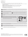
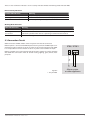
COMMUNICATOR
ET08 / ET081
User Manual v1.2
Safety instructions
Please read and follow these safety guidelines in order to maintain safety of operators and people around:
• GSM communicator ET08 / ET081 (further referenced as system or device) contains a radio transceiver operating in
GSM850/900/1800/1900 bands.
• DO NOT use the system where it can interfere with other devices and cause any potential danger.
• DO NOT use the system with medical devices if this is required in the manual of the medical device.
• DO NOT use the system in hazardous environment.
• DO NOT expose the system to high humidity, chemical environment or mechanical impacts.
• DO NOT attempt to personally repair the system.
• System labelling sticker is at the bottom of the device.
System ET08 / ET081 is a device mounted in limited access areas. Any system repairs must be done only by qualified, safety
aware personnel.
Mains power must be disconnected before any installation or tuning work starts. The system installation or maintenance
must not be done during stormy conditions.
The system must be powered by main 10-24V
dard and be easily accessible.
������������������������������������������������������������������
300mA power supply which must be approved by LST EN 60950-1 stan-
Any additional devices linked to the system ET08 / ET081 (computer, sensors, relays etc.) must be approved by LST EN 609501 standard.
External power supply can be connected to AC mains only inside installation room with automatic 2-pole circuit breaker capable of disconnecting circuit in the event of short circuit or over-current condition.
Open circuit breaker must have a gap between connections of more
than 3mm and the disconnection current is 5A.
Phase
Null
PE
AC 230V
50 Hz/DC 24V
ET08/
ET081
USB cable
Fuse F1 model - miniSMDC 500mA. Blown fuse cannot be replaced by the user and the replacement fuses have to be exactly
the same as indicated by the manufacturer.
The device is fully turned off by disconnecting 2-pole switch off device of the external power supply or any other linked
device that the system ET08 / ET081 is powered from.
The WEEE (Waste Electrical and Electronic Equipment) marking on this product (see left) or its documentation indicates that in the EU
the product must not be disposed of together with household waste.
Copyright © “ELDES UAB”, 2011. All rights reserved.
It is strictly forbidden to copy and distribute information in this document or pass to a third party without an advanced written authorization from
“ELDES UAB”. “ELDES UAB” reserves the right to update or modify this document and/or related products without a warning. Hereby, ELDES UAB
declares that this communicator ET08 / ET081 is in compliance with the essential requirements and other relevant provisions of Directive 1999/5/EC.
The declaration of conformity may be consulted at www.eldes.lt
Limited Liability
The buyer must agree that the system will reduce the risk of fire, theft, burglary or other dangers
but does not guarantee against such events. “ELDES UAB” will not take any responsibility regarding
personal, property or revenue loss while using the
system. “ELDES UAB” responsibility according to
local laws does not exceed value of the purchased
system. “ELDES UAB” is not affiliated with GSM operators providing cellular services, therefore is not
responsible for network services, coverage or its
operation.
CONTENTS
1. General Information...................................................................... 4
1.1 Operation Description................................................................................4
2. Technical Specifications............................................................... 5
2.1 Electrical & Mechanical Specifications..................................................5
2.2 Main Unit, Connector, Pin & LED Functionality..................................5
2.2.1 Main Unit Functionality..........................................................................6
2.2.2 Connector Functionality.........................................................................6
2.2.3 Pin Functionality........................................................................................6
2.2.4 LED Functionality......................................................................................6
2.3 Connection Circuit.......................................................................................7
Manufacturer Warranty
3. Installation..................................................................................... 8
The system carries a 24-month warranty by the
manufacturer “ELDES UAB”.
4. Communication Modes................................................................. 9
Warranty period starts from the day the system
has been purchased by the end user. The warranty
is valid only if the system has been used as intended, following all guidelines listed in the manual
and within specified operating conditions. Receipt
with purchase date must be kept as a proof.
The warranty is voided if the system has been
exposed to mechanical impacts, chemicals, high
humidity, fluids, corrosive and hazardous environment or other force majeure factors.
Package Content
1. System ET08 / ET081............................................1 pcs
2. ET08 / ET081 user manual.................................1 pcs
3. GSM antenna..........................................................1 pcs
4. Jumpers...................................................................4 pcs.
5. Fastening holders................................................4 pcs.
About User Manual
This document describes communicator ET08 /
ET081, its operation and installation. It is very important to read User Manual before start using the
system.
4.1 Communication Mode 1. Data Transmission from Alarm
System to Monitoring Station via GSM Audio Channel .............9
4.2 Communication Mode 2. Data Transmission from Alarm
System to Preset User (-s) by SMS..................................................... 10
4.3 Communication Mode 3. Data Transmission
from Alarm System to Monitoring Station via GSM
Audio Channel and SMS Messages to Preset User (-s).............. 11
4.4 Communication Mode 4. Data Transmission from
Alarm System to Monitoring Station via GPRS Network......... 12
4.5 Communication Mode 5. Data Transmission
from Alarm System to Monitoring Station via PSTN
using GSM Audio Channel as Backup Connection..................... 13
4.6 Communication Mode 6. Data Transmission
from Alarm System to Monitoring Station via PSTN
using SMS Messages as Backup Connection................................ 14
4.7 Communication Mode 7. Data Transmission
from Alarm System to Monitoring Station via PSTN
using GSM Audio Channel as Backup Connection
and SMS Messages to Preset User (-s)............................................. 15
4.8 Communication Mode 8. Data Transmission
from Alarm System to Monitoring Station via PSTN
using GPRS Network as Backup Connection................................. 16
4.9 Communication Mode 9. Data Transmission from Alarm
System to Monitoring Station via PSTN through PBX
using GSM Audio Channel as Backup Connection..................... 17
4.10 Communication Mode 10. Data Transmission from Alarm
System to Monitoring Station via PSTN through PBX
using SMS Messages as Backup Connection................................ 18
4.11 Communication Mode 11. Data Transmission
from Alarm System to Monitoring Station via PSTN
through PBX using GSM Audio Channel as a Backup
Connection and SMS Messages to Preset User (-s)..................... 19
4.12 Communication Mode 12. Data Transmission from
Alarm System to Monitoring Station via PSTN through
PBX using GPRS Network as Backup Connection........................ 20
5. SMS Commands*.........................................................................22
6. Appendix ...................................................................................24
6.1 Restoring Default Parameters ............................................................. 24
6.2 Upgrading Firmware................................................................................ 24
6.3 ELDES Configuration Tool Software.................................................... 24
6.4 Technical Support...................................................................................... 25
1. General Information
Communicator ET08 / ET081 is a device for transmitting data from alarm system to monitoring station via:
•
•
•
•
GSM audio channel;
GSM audio channel and/or to users via SMS message;
Telehone landline (PSTN);
GPRS network.
The system can be used in the following applications:
•
•
Property security.
GSM network backup for PSTN.
1.1 Operation Description
ET08 / ET081 communicator acts as a gateway between the alarm system and monitoring station providing a dial tone and fully
replacing the landline (PSTN). The communicator notifies monitoring station (ET081 ONLY) and/or the preset user by SMS message
in case PSTN is unavailable, has been cut off or disconnected by PSTN provider. ET08 / ET081 supports only outgoing calls. DTMF
number dialing mode in alarm system must be enabled.
ET08 / ET081 can detect temporary service suspension by the service provider for technical or billing reasons even if a dial tone is
still present (optional feature).
ET08 / ET081 features several communication ways between alarm system and monitoring station via:
1. GSM audio channel;
2. PSTN using GSM audio channel as backup connection;
3. SMS messages to preset users;
4. PSTN using GSM audio channel as backup connection with data duplication to preset users via SMS;
5. GPRS network.
6. PSTN using GPRS network as backup connection.
Please, refer to chapter 4. Communication Modes for more details.
The system ET08 / ET081 has 1 digital input (normally open) for sensor connection. The open collector output allows to connect
and control 1 electronic appliance on receipt of the correct SMS text message from one of the preset phone numbers. This feature
provides control over heating, lighting, gates, blinds etc.
ELDES Configuration Tool software is used to configure the system to operate in one of its communication modes, providing data
transmission either via SMS text message or via GPRS. The device has to be connected to the computer using a USB cable. Please,
refer to software‘s HELP section for more details.
4
2. Technical Specifications
2.1 Electrical & Mechanical Specifications
Power Supply
10-24V
Current Used in Standby Mode
120mA max
300mA max
GSM Modem Frequency
850/900/1800/1900 MHz
Supported Protocols
Contact ID, 4+2**
Maximum Number of Users to whom SMS Messages are De- 5
livered
Number of “Low” Level (Negative) Digital Inputs*
1
Allowable Input Values*
Voltage: 0... 1.45V; current: 0.8... 0.6mA
Input Type
NO (normally open)
Number of Outputs*
1
Output Circuit*
Open collector output. Output is pulled to COM when turned
on.
Maximum Allowed Output Values*
Voltage: 30V ; current: 50 mA
Dimensions
130 x 73 mm
Operating temperature range
-20...+55oC
Generated Phone Line Voltage
18 V
Generated Phone Line Current
25 mA
Generated Phone Line Impedance
600 Ω
Dial Tone Frequency of Generated Phone line
350 Hz
* only in ET081
** 4+2 protocol operates in communication mode 1, 5 and 9 ONLY (via GSM audio channel).
2.2 Main Unit, Connector, Pin & LED Functionality
For configurations
DEFAULT
GSM
MODEM
SET
MODE
PROG
SIM CARD
ANT
USB
INFO
B1
STATUS
GSM
B2
F1
L1 L2
L3
L4 RING TIP
USER MANUAL ELDES ET08 / ET081 V1.2
C1 DC+ COM
N/A N/A Z1
Fig. No 1
5
2.2.1 Main Unit Functionality
GSM MODEM
GSM network 850/900/1800/1900 MHz modem
SIM CARD
SIM card slot / holder
ANT
GSM antenna SMA type connector
F1
Fuse model – miniSMDC 500mA
USB
Mini USB port
2.2.2 Connector Functionality
Labelling
Description
L1 - L4
Landline or PBX contacts (according to backup mode)
RING
RING contact
TIP
TIP contact
C1
Output
DC+
Positive power supply contact
COM
Negative power supply contact / Common contact
Z1
Input
N/A
Not available
2.2.3 Pin Functionality
Labelling
Description
DEFAULT
For restoring factory default settings
SET
For enabling communication modes
MODE
For enabling communication modes
B1, B2
For communication backup connection
PROG
Not used
2.2.4 LED Functionality
Labelling
Description
INFO
Working mode indicator
STATUS
Device activity indicator
GSM
GSM network quality indicator
GSM Signal Strength Indication
GSM signal strength is indicated by GSM LED. To ensure the best quality of the network adjust the position of GSM antenna and
find the strongest possible signal by observing the GSM LED indications.
GSM LED Indication
GSM Signal Strength
Off
No connection
Flashing every 3 seconds
The connection is not reliable
Flashing every 1 second
Satisfactory
Flashing several times per second
Good
On
Excellent
It is recommended to install the GSM antenna away from the alarm system to ensure better quality of the audio signal. It is not
recommend to install the antenna inside the metal enclosure.
6
There are also a few other indicators - device activity indicator STATUS and working mode indicator INFO.
Device Activity Indication
STATUS LED Indication
Meaning
Off
No power supply or some fault is present
Flashing several times per second
SIM card is not inserted / insterted improperly
On
Device is operating and ready for use
Working Mode Indication
INFO LED Indication
Meaning
Off
Device is in standby mode
Flashing several times
per second
Device retransmits the data sent from alarm system to the monitoring station (this
indication is possible when device is operating in communication mode 1)
On
Device is decoding Contact ID data to user-understandable text format.
2.3 Connection Circuit
COM connectors of ET08 / ET081 and alarm system unit must be connected.
ET081 Input Z1 is connected to PGM output of alarm system unit if PGM output is implemented as open collector circuit or any other circuit and if it commutes with COM.
It is also possible to connect motion sensor or any other sensor to ET081 Z1 input.
ET081 C1 output can be connected to input of electronic appliance and if it commute
with COM. This connection allows to control heating, lighting, gates, blinds, water
pump etc.
ET08 / ET081
Z1*
DC+ COM C1*
PGM
+12V
Fig. No 2
* - only in ET081
USER MANUAL ELDES ET08 / ET081 V1.2
Alarm system
or other appliance
7
3. Installation
NOTE: Due to GSM network characteristics it is recommended that ET08/ET081 be equipped with a SIM card from the same
GSM operator who provided the SIM cards used by users who will receive messages from the system. Thus you will ensure the
quickest SMS message delivery and receipt.
NOTE: To ensure maximum system operation reliability we recommend not to use pay-as-you-go SIM cards. If the balance is
insufficient the system will not be able to inform users by SMS or send Contact ID messages.
IMPORTANT: Power supply at alarm system must be disconnected before any installation or tuning work.
The system can be installed in a metal or non-flammable plastic enclosure together with alarm control panel. When the metal
enclosure is also used it is necessary to ground the enclosure using yellow/green colour cable. For the connection use 0.50 mm2
1 thread cable.
Device Installation and Pre-operation:
1. Fasten the system in the enclosure using fastening holders.
2. Place SIM card into the SIM card slot and fix it with holder after making sure that SIM card PIN code is disabled. PIN code
can be disabled by inserting the SIM card into mobile phone and following proper menus. SIM card should not have any
remaining SMS messages.
3. Connect the GSM antenna to SMA connector. It is not recommended to turn on the device without GSM antenna connected.
4. Connect the circuit according to desired communication mode (see chapter 4. Communication Modes)
5. The system should start in less than a minute. GSM LED indicator should be blinking or be ON indicating successful connection to GSM network.
8
4. Communication Modes
ATTENTION: DTMF phone number dialing mode must be enabled on alarm system, activated Contact ID or 4+2 data
transmission protocol and monitoring station phone number set with international code, i.e. For UK London 20xxxxxxxx or
004420xxxxxxxx. The <plus> character is not allowed.
4.1 Communication Mode 1. Data Transmission from Alarm System
to Monitoring Station via GSM Audio Channel
In this mode the communicator retransmits Contact ID or 4+2 data sent from alarm system to monitoring station via GSM audio
channel. There is NO backup connection for this mode.
NOTE: No additional communicator configuration is required for this mode.
L1 L2 L3
L4 RING TIP
RING/TIP
C1 DC+ COM
N/A N/A Z1
AUX+ AUX-
ALARM SYSTEM
Fig. No 3
1. Connect the circuit as indicated in Fig. No. 3 – connect telephone contacts of the alarm system RING/TIP to RING/TIP contacts of the communicator.
2. Connect power supply to DC+/COM contacts. Power supply is usually used as AUX- and AUX+ output of alarm system.
3. No jumpers have to be set on any pins. See Fig. No. 4 for correct jumper position.
Fig. No 4
USER MANUAL ELDES ET08 / ET081 V1.2
9
4.2 Communication Mode 2. Data Transmission
from Alarm System to Preset User (-s) by SMS.
In this mode the communicator retransmits Contact ID data sent from alarm system and decodes it to user-understandable text
format which is sent to preset user (-s) by SMS message. There is NO backup connection for this mode.
NOTE: User phone number (-s) must be set for the communicator using ELDES Configuration Tool. Please, refer to software's
HELP section for more details.
ATTENTION: It is also necessary to set monitoring station phone number on alarm system in this mode. In such case you can
use any number (one digit is enough).
L1 L2 L3
L4 RING TIP
RING/TIP
C1 DC+ COM
N/A N/A Z1
AUX+ AUX-
ALARM SYSTEM
Fig. No 5
1. Connect the circuit as indicated in Fig. No. 5 – connect telephone contacts of the alarm system RING/TIP to RING/TIP contacts of the communicator.
2. Connect power supply to DC+/COM contacts. Power supply is usually used as AUX- and AUX+ output of alarm system.
3. Set the jumper on MODE pins. See Fig. No. 6 for correct jumper position.
Fig. No 6
10
4.3 Communication Mode 3. Data Transmission from Alarm System to
Monitoring Station via GSM Audio Channel and SMS Messages to Preset User (-s)
In this mode the communicator retransmits Contact ID data sent from alarm system to monitoring station via GSM audio channel.
In addition, the data is duplicated and decoded data to user-understandable text format and sent to preset user (-s) by SMS message. There is NO backup connection for this mode.
NOTE: User phone number (-s) must be set for the communicator using ELDES Configuration Tool. Please, refer to software's
HELP section for more details.
L1 L2 L3
L4 RING TIP
RING/TIP
C1 DC+ COM
N/A N/A Z1
AUX+ AUX-
ALARM SYSTEM
Fig. No 7
1. Connect the circuit as indicated in Fig. No. 7 – connect telephone contacts of the alarm system RING/TIP to RING/TIP contacts of the communicator.
2. Connect power supply to DC+/COM contacts. Power supply is usually used as AUX- and AUX+ output of alarm system.
3. Set the jumper on SET pins. See Fig. No. 8 for correct jumper position.
Fig. No 8
USER MANUAL ELDES ET08 / ET081 V1.2
11
4.4 Communication Mode 4. Data Transmission from Alarm System
to Monitoring Station via GPRS Network
NOTE: EGR100 software is required for this communication mode. The software is freeware and can be downloaded from
ELDES website at www.eldes.lt
In this mode the communicator retransmits Contact ID data via GPRS network sent from alarm system to monitoring station. There
is NO backup connection for this mode.
I. The following communicator GPRS settings must be set up using ELDES Configuration Tool software:
•
•
•
•
•
•
CID over GPRS Enabled – enables Contact ID data transmission via GPRS network.
APN – access-point-name provided by GSM operator.
User Name – user name provided by GSM operator.
Password – password provided by GSM operator.
Server IP – external IP address of the computer (router) running EGR100 software.
Server Port – forwarded UDP port for the computer running EGR100 software.
Please, refer to ELDES Configuration Tool software's HELP section for more details.
II. The following settings must be set up in EGR100 software:
• TCP/UDP Server Port - forwarded port for communication with the device via GPRS.
Please, refer to EGR100 software's user guide for more details.
NOTE: UDP port must be set the same both on the communicator using ELDES Configuration Tool and in EGR100 software.
L1 L2 L3
L4 RING TIP
RING/TIP
C1 DC+ COM
N/A N/A Z1
AUX+ AUX-
ALARM SYSTEM
Fig. No 9
1. Connect the circuit as indicated in Fig. No. 9 – connect telephone contacts of the alarm system RING/TIP to RING/TIP contacts of the communicator.
2. Connect power supply to DC+/COM contacts. Power supply is usually used as AUX- and AUX+ output of alarm system.
3. Set the jumpers on SET and MODE pins. See Fig. No. 10 for correct jumper position.
Fig. No 10
12
4.5 Communication Mode 5. Data Transmission from Alarm System to Monitoring
Station via PSTN using GSM Audio Channel as Backup Connection
In this mode the communicator retransmits Contact ID and 4+2 data via landline (PSTN) sent from alarm system to monitoring station. The communicator also monitors the voltage (dial tone monitoring optional) on the PSTN and in case the PSTN is unavailable,
disconnected or cut off (voltage drops below 4V), the system:
• switches to backup connection – GSM audio channel,
• notifies monitoring station about PSTN failure,
• continues transmitting data to monitoring station via GSM audio channel until the PSTN is restored.
NOTE: Notification about PSTN loss/restore (if required) has to be enabled for the communicator using ELDES Configuration
Tool. Please, refer to software‘s HELP section for more details.
L1 L2 L3
To landline
(PSTN)
L4 RING TIP
RING/TIP
C1 DC+ COM
N/A N/A Z1
AUX+ AUX-
ALARM SYSTEM
Fig. No 11
1. Connect the circuit as indicated in Fig. No. 11 – connect telephone contacts of the alarm system RING/TIP to RING/TIP
contacts of communicator.
2. Connect L3/L4 contacts to landline (PSTN).
3. Connect power supply to DC+/COM contacts. Power supply is usually used as AUX- and AUX+ output of alarm system.
4. Set the jumpers on B1 and B2 pins. See Fig. No. 12 for correct jumper position.
Fig. No 12
USER MANUAL ELDES ET08 / ET081 V1.2
13
4.6 Communication Mode 6. Data Transmission from Alarm System to Monitoring
Station via PSTN using SMS Messages as Backup Connection
In this mode the communicator retransmits Contact ID data via landline (PSTN) sent from alarm system to monitoring station. The
communicator also monitors the voltage (dial tone monitoring optional) on the PSTN and in case the PSTN is unavailable, disconnected or cut off (voltage drops below 4V), the system:
• sends an SMS report to the preset user (-s) on PSTN failure,
• decodes data to user-understandable text format and continues transmitting it to preset user (-s) by SMS message until the
PSTN is restored.
NOTE: User phone number (-s) must be set for the communicator using ELDES Configuration Tool. Please, refer to software's
HELP section for more details.
L1 L2 L3
To landline
(PSTN)
L4 RING TIP
RING/TIP
C1 DC+ COM
N/A N/A Z1
AUX+ AUX-
ALARM SYSTEM
Fig. No 13
1. Connect the circuit as indicated in Fig. No. 13 – connect telephone contacts of the alarm system RING/TIP to RING/TIP
contacts of communicator.
2. Connect L3/L4 contacts to landline (PSTN).
3 Connect power supply to DC+/COM contacts. Power supply is usually used as AUX- and AUX+ output of alarm system.
4. Set the jumpers on B1, B2 and MODE pins. See Fig. No. 14 for correct jumper position.
Fig. No 14
14
4.7 Communication Mode 7. Data Transmission from Alarm System
to Monitoring Station via PSTN using GSM Audio Channel as
Backup Connection and SMS Messages to Preset User (-s)
In this mode the communicator retransmits Contact ID data via landline (PSTN) sent from alarm system to monitoring station. The
communicator also monitors the voltage (dial tone monitoring optional) on the PSTN and in case the PSTN is unavailable, disconnected or cut off (voltage drops below 4V), the system:
•
•
•
•
•
switches to backup connection – GSM audio channel,
notifies monitoring station about PSTN failure,
sends an SMS report to the preset user (-s) on PSTN failure,
continues transmitting data to monitoring station via GSM audio channel until the PSTN is restored,
duplicates and decodes data to user-understandable text format and sends it to preset user (-s) by SMS message until the
PSTN is restored.
NOTE: User phone number (-s) must be set and notification about PSTN loss/restore (if required) has to be enabled for the
communicator using ELDES Configuration Tool. Please, refer to software‘s HELP section for more details. for more details.
L1 L2 L3
To landline
(PSTN)
L4 RING TIP
RING/TIP
C1 DC+ COM
N/A N/A Z1
AUX+ AUX-
ALARM SYSTEM
Fig. No 15
1. Connect the circuit as indicated in Fig. No. 15 – connect telephone contacts of the alarm system RING/TIP to RING/TIP
contacts of communicator.
2. Connect L3/L4 contacts to landline (PSTN).
3. Connect power supply to DC+/COM contacts. Power supply is usually used as AUX- and AUX+ output of alarm system.
4. Set the jumpers on B1, B2 and SET pins. See Fig. No. 16 for correct jumper position.
Fig. No 16
USER MANUAL ELDES ET08 / ET081 V1.2
15
4.8 Communication Mode 8. Data Transmission from Alarm System to
Monitoring Station via PSTN using GPRS Network as Backup Connection
In this mode the communicator retransmits Contact ID data via landline (PSTN) sent from alarm system to monitoring station. The
communicator also monitors the voltage (dial tone monitoring optional) on the PSTN and in case the PSTN is unavailable, disconnected or cut off (voltage drops below 4V), the system:
• switches to backup connection – GPRS network,
• notifies monitoring station about PSTN failure,
• continues transmitting data to monitoring station via GPRS network until the PSTN is restored.
NOTE: Notification about PSTN loss/restore (if required) has to be enabled for the communicator using
Please, refer to software‘s HELP section for more details.
I. The following communicator GPRS settings must be set up using ELDES Configuration Tool software:
•
•
•
•
•
•
CID over GPRS Enabled – enables Contact ID data transmission via GPRS network.
APN – access-point-name provided by GSM operator.
User Name – user name provided by GSM operator.
Password – password provided by GSM operator.
Server IP – external IP address of the computer (router) running EGR100 software.
Server Port – forwarded UDP port for the computer running EGR100 software.
Please, refer to ELDES Configuration Tool software's HELP section for more details.
II. The following settings must be set up in EGR100 software:
• TCP/UDP Server Port - forwarded port for communication with the device via GPRS.
Please, refer to EGR100 software's user guide for more details.
NOTE: UDP port must be set the same both on the communicator using ELDES Configuration Tool and in EGR100 software.
L1 L2 L3
To landline
(PSTN)
L4 RING TIP
RING/TIP
C1 DC+ COM
N/A N/A Z1
AUX+ AUX-
ALARM SYSTEM
Fig. No 17
1. Connect the circuit as indicated in Fig. No. 17 – connect telephone contacts of the alarm system RING/TIP to RING/TIP
contacts of communicator.
2. Connect L3/L4 contacts to landline (PSTN).
3. Connect power supply to DC+/COM contacts. Power supply is usually used as AUX- and AUX+ output of alarm system.
4. Set the jumpers on B1, B2, SET and MODE pins. See Fig. No. 18 for correct jumper position.
Fig. No 18
16
F O R A D VA N C E D U S E R S O N LY !
4.9 Communication Mode 9. Data Transmission from Alarm System to Monitoring
Station via PSTN through PBX using GSM Audio Channel as Backup Connection
In this mode the communicator retransmits alarm system Contact ID or 4+2 data to monitoring station via landline (PSTN) through
private branch exchange station (PBX). The communicator also monitors the voltage (dial tone monitoring optional) on the external PSTN. In case the external PSTN is unavailable, disconnected or cut off (voltage drops below 4V), the system:
• switches to backup connection – GSM audio channel,
• notifies monitoring station about PSTN failure,
• continues transmitting data to monitoring station via GSM audio channel until the external PSTN is restored.
NOTE: Notification about PSTN loss/restore (if required) has to be enabled for the communicator using ELDES Configuration
Tool. Please, refer to software‘s HELP section for more details.
To external
landline (PSTN)
L1 L2 L3
PBX
L4 RING TIP
C1 DC+ COM
RING TIP
AUX+ AUX-
ALARM SYSTEM
Internal
landline (PSTN)
N/A N/A Z1
Fig. No 19
1. Connect the circuit as indicated in Fig. No. 19 – connect telephone contacts of the alarm system RING/TIP to RING/TIP
contacts of communicator.
2. Connect L1/L2 contacts to external landline (PSTN).
3. Connect L3/L4 contacts to internal landline (PSTN) of PBX.
4. Connect power supply to DC+/COM contacts. Power supply is usually used as AUX- and AUX+ output of alarm system.
5. No jumpers have to be set on any pins. See Fig. 20 for correct jumper position.
Fig. No 20
USER MANUAL ELDES ET08 / ET081 V1.2
17
F O R A D VA N C E D U S E R S O N LY !
4.10 Communication Mode 10. Data Transmission from Alarm System to Monitoring
Station via PSTN through PBX using SMS Messages as Backup Connection
In this mode the communicator retransmits alarm system Contact ID data to monitoring station via landline (PSTN) through private branch exchange station (PBX). The communicator also monitors the voltage (dial tone monitoring optional) on the external
PSTN. In case the external PSTN is unavailable, disconnected or cut off (voltage drops below 4V), the system:
• sends an SMS report to the preset user (-s) on PSTN failure,
• decodes data to user-understandable text format and continues transmitting it to preset user (-s) by SMS message until the
external PSTN is restored.
NOTE: User phone number (-s) must be set and notification about PSTN loss/restore (if required) has to be enabled for the
communicator using ELDES Configuration Tool. Please, refer to software‘s HELP section for more details.
To external
landline (PSTN)
L1 L2 L3
PBX
L4 RING TIP
C1 DC+ COM
RING TIP
AUX+ AUX-
ALARM SYSTEM
Internal
landline (PSTN)
N/A N/A Z1
Fig. No 21
1. Connect the circuit as indicated in Fig. No. 21 – connect telephone contacts of the alarm system RING/TIP to RING/TIP
contacts of communicator.
2. Connect L1/L2 contacts to external landline (PSTN).
3. Connect L3/L4 contacts to internal landline (PSTN) of PBX.
4. Connect power supply to DC+/COM contacts. Power supply is usually used as AUX- and AUX+ output of alarm system.
5. Set the jumper on MODE pins. See Fig. No. 22 for correct jumper position.
Fig. No 22
18
F O R A D VA N C E D U S E R S O N LY !
4.11 Communication Mode 11. Data Transmission from Alarm System to
Monitoring Station via PSTN through PBX using GSM Audio Channel
as Backup Connection and SMS Messages to Preset User (-s)
In this mode the communicator retransmits alarm system Contact ID data to monitoring station via landline (PSTN) through private branch exchange station (PBX). The communicator also monitors the voltage (dial tone monitoring optional) on the external
PSTN. In case the external PSTN is unavailable, disconnected or cut off (voltage drops below 4V), the system:
•
•
•
•
•
switches to backup connection – GSM audio channel,
notifies monitoring station about PSTN failure,
sends an SMS report to the preset user (-s) on PSTN failure,
continues transmitting data to monitoring station via GSM audio channel until the external PSTN is restored,
duplicates and decodes data to user-understandable text format and sends it to preset user (-s) by SMS message until the
external PSTN is restored.
NOTE: User phone number (-s) must be set and notification about PSTN loss/restore (if required) has to be enabled for the
communicator using ELDES Configuration Tool. Please, refer to software‘s HELP section for more details.
To external
landline (PSTN)
L1 L2 L3
PBX
L4 RING TIP
C1 DC+ COM
RING TIP
AUX+ AUX-
ALARM SYSTEM
Internal
landline (PSTN)
N/A N/A Z1
Fig. No 23
1. Connect the circuit as indicated in Fig. No. 23 – connect telephone contacts of the alarm system RING/TIP to RING/TIP
contacts of communicator.
2. Connect L1/L2 contacts to external landline (PSTN).
3. Connect L3/L4 contacts to internal landline (PSTN) of PBX.
4. Connect power supply to DC+/COM contacts. Power supply is usually used as AUX- and AUX+ output of alarm system.
5. Set the jumper on SET pins. See Fig. No. 24 for correct jumper position.
Fig. No 24
USER MANUAL ELDES ET08 / ET081 V1.2
19
F O R A D VA N C E D U S E R S O N LY !
4.12 Communication Mode 12. Data Transmission from Alarm System to Monitoring
Station via PSTN through PBX using GPRS Network as Backup Connection
In this mode the communicator retransmits alarm system Contact ID data to monitoring station via landline (PSTN) through private branch exchange station (PBX). The communicator also monitors the voltage (dial tone monitoring optional) on the external
PSTN. In case the external PSTN is unavailable, disconnected or cut off (voltage drops below 4V), the system:
• switches to backup connection – GPRS network,
• notifies monitoring station about PSTN failure,
• continues transmitting data to monitoring station via GPRS network until the external PSTN is restored.
NOTE: Notification about PSTN loss/restore (if required) has to be enabled for the communicator using ELDES Configuration
Tool. Please, refer to software‘s HELP section for more details.
I. The following communicator GPRS settings must be set up using ELDES Configuration Tool software:
•
•
•
•
•
•
CID over GPRS Enabled – enables Contact ID data transmission via GPRS network.
APN – access-point-name provided by GSM operator.
User Name – user name provided by GSM operator.
Password – password provided by GSM operator.
Server IP – external IP address of the computer running EGR100 software.
Server Port – forwarded UDP port for the computer running EGR100 software.
Please, refer to ELDES Configuration Tool software's HELP section for more details.
II. The following settings must be set up in EGR100 software:
• TCP/UDP Server Port - forwarded port for communication with the device via GPRS.
Please, refer to EGR100 software's user guide for more details.
NOTE: UDP port must be set the same both on the communicator using ELDES Configuration Tool and in EGR100 software.
To external
landline (PSTN)
L1 L2 L3
PBX
L4 RING TIP
C1 DC+ COM
RING TIP
AUX+ AUX-
ALARM SYSTEM
Internal
landline (PSTN)
20
N/A N/A Z1
Fig. No 25
F O R A D VA N C E D U S E R S O N LY !
1. Connect the circuit as indicated in Fig. No. 25 – connect telephone contacts of the alarm system RING/TIP to RING/TIP
contacts of communicator.
2. Connect L1/L2 contacts to external landline (PSTN).
3. Connect L3/L4 contacts to internal landline (PSTN) of PBX.
4. Connect power supply to DC+/COM contacts. Power supply is usually used as AUX- and AUX+ output of alarm system.
5. Set the jumper on SET and MODE pins. See Fig. No. 26 for correct jumper position.
Fig. No 26
USER MANUAL ELDES ET08 / ET081 V1.2
21
5. SMS Commands*
* - only in ET081
ATTENTION! In this user manual the underscore _ character represents one <space> character. There must be no spaces or
other characters at the beginning and at the end of the message. XXXX – 4-digit SMS password.
In order to configure and control ET081 system using SMS message, send the text command to ET081 SIM card phone number
from one of the authorized phone numbers. The structure of SMS message consists of 4-digit SMS password (the default SMS password is 0000 – four zeros), the command and the parameters. For some commands the parameters are not applied, i.e. STATUS.
ET081 notifies the user if a mistake was made in SMS command: “Command is not correct”.
Status
The SMS report indicating information on system input and output status.
SMS text:
XXXX_STATUS
Password
The 4-digit SMS password intended for system configuration and control via SMS messages.
Manufacturer default SMS password is 0000 (four zeros) which is NECESSARY to change.
SMS text:
0000_PSW_XXXX
Value: XXXX – new 4-digit password.
Output ON
This function switches the output ON.
SMS text:
XXXX_ON
22
Output OFF
This function switches the output OFF.
SMS text:
XXXX_OFF
Output Pulse ON
This function switches the output ON for a set period of time and switches the output back to
OFF after the set period of time is over.
SMS text:
XXXX_ON_T
Value: T – period of time in seconds, range - [1-9999]
Output Pulse OFF
This function switches the output OFF for a set period of time and switches the output back to
ON after the set period of time is over.
SMS text:
XXXX_OFF_T
Value: T – period of time in seconds, range - [1-9999]
Telephone Line
Failure/Restore Delay
The delay period of time between telephone line failure and restore events. If telephone line
failure and restore events occur before the set delay period of time is over, the system will not
send the SMS report.
SMS text:
XXXX_TELDLY_T
Value: T – period of time in seconds, range - [1-250]
USER MANUAL ELDES ET08 / ET081 V1.2
23
6. Appendix
6.1 Restoring Default Parameters
To restore the default parameters:
1.
2.
3.
4.
5.
6.
Disconnect the power supply;
Short circuit (connect) DEFAULT pins;
Power up ET08 / ET081 for 7 seconds;
Disconnect the power supply;
Remove short circuit from DEFAULT pins;
Parameters restored to default.
6.2 Upgrading Firmware
1. Disconnect the power supply and backup battery.
2. Short circuit (connect) DEFAULT pins.
3. Connect the device via USB cable to the PC.
4. Power up the device.
5. The new window must pop-up where you will find the .bin file. Otherwise open My Computer and look for Boot Disk drive.
6. Delete the .bin file found in the drive.
7. Copy the new firmware .bin file to the very same window.
8. Power down the device.
9. Unplug USB cable.
10. Remove short circuit from DEFAULT pins.
11. Power up the device.
12. Firmware upgraded.
NOTE: It is strongly recommended to restore default parameters after the firmware upgrade.
6.3 ELDES Configuration Tool Software
To configure the system, please install configuration software ELDES Configuration Tool which can be downloaded from ELDES
website at www.eldes.lt
Before connecting USB cable to the computer, please, read ELDES Configuration Tool user guide available in the HELP section of the
software.
24
6.4 Technical Support
Indication
Possible Reason
GSM LED is off or not flashing
•
•
•
•
No external power supply
Circuit not properly connected
Blown fuse
No GSM network signal
STATUS LED flashing several times per second
•
•
•
SIM card not inserted / improperly inserted
PIN code enabled
SIM card inactive
System does not send any SMS messages
•
•
•
•
SIM card credit limit exceeded
Incorrect SMS centre phone number
No GSM network signal
User phone number is not preset.
Received SMS message “Incorrect Format”
or “Command is not correct”
•
Incorrect syntax
Extra <space> character is left in SMS message
For product warranty repair service, please, contact your local retail store where this product was purchase.
If your problem could not be fixed by the self-guide above, please, contact your distributor or ELDES technical support by email
[email protected]
More up to date information about your device and other products can be found at the manufacturer‘s website www.eldes.lt
USER MANUAL ELDES ET08 / ET081 V1.2
25
For notes
26
For notes
USER MANUAL ELDES ET08 / ET081 V1.2
27
Made in Lithuania.
www.eldes.lt