1
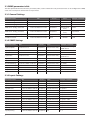
I/O ETHERNET CONTROLLER ELAN1 Manual v1.0 Safety instructions Please read and follow these safety guidelines in order to maintain safety of operators and people around: • • • • Don’t use the system in hazardous environment. Don’t expose the system to high humidity, chemical environment or mechanical impacts. Don’t attempt to personally repair the system. System label is on the bottom side of the device. System ELAN1 is a device mounted in limited access areas. Any system repairs must be done only by qualified, safety aware personnel. The system must be powered by main 10-24V 120mA max/ 10-24V 50Hz~ 120mA max power supply which must be approved by LST EN 60950-1 standard and be easily accessible. External power supply must be reachable and can be connected to AC mains only inside installation room with automatic 2-pole circuit breaker capable of disconnecting circuit in the event of short circuit or overcurrent condition. Open circuit breaker must have a gap between connections of more than 3mm. Phase Null PE AC 230V 50 Hz/DC 24V ELAN1 USB cable Mains power must be disconnected before any installation or tuning work starts. The system installation or maintenance must not be done during stormy conditions. The device is switched off by 2-pole circuit breaker. Fuse F1 type – miniSMDC 0,5A. Replacement fuses have to be exactly the same as indicated by the manufacturer. Any additional devices linked to the system ELAN1 (computer, sensors, relays etc.) must be approved by LST EN 60950-1 standard. The device is fully turned off by disconnecting 2-pole switch off device of the external power supply or any other linked device that the system ELAN1 is powered from. If you use I security class computer for setting the parameters it must be connected to earth. The WEEE (Waste Electrical and Electronic Equipment) marking on this product (see right) or its documentation indicates that the product must not be disposed of together with household waste. To prevent possible harm to human health and/or the environment, the product must be disposed on in an approved and environmentally safe recycling process. For further information on how to dispose of this product correctly, contact the system supplier, or the local authority responsible for waste disposal in your area. Copyright © “ELDES UAB”, 2011. All rights reserved It is not allowed to copy and distribute information in this document or pass to a third party without advanced written authorization by “ELDES UAB”. “ELDES UAB” reserves the right to update or modify this document and/or related products without a warning. Hereby, ELDES UAB declares that this ELAN1 device is in compliance with the essential requirements and other relevant provisions of Directive 1999/5/EC. The declaration of conformity may be consulted at www.eldes.lt Limited Liability The buyer must agree that the system will reduce the risk of fire, theft, burglary or other dangers but does not guarantee against such events. “ELDES UAB” will not take any responsibility regarding personal or property or revenue loss while using the system. “ELDES UAB” liability according to local laws does not exceed value of the purchased system. “ELDES UAB” is not affiliated with any of the Internet providers therefore is not responsible for the quality of Internet service. Manufacturer Warranty This device carries a 24-month warranty by the manufacturer “ELDES UAB”. Warranty period starts from the day the system has been purchased by the end user. The warranty is valid only if the system has been used as intended, following all guidelines listed in the manual and within specified operating conditions. Receipt must be kept as a proof of purchase date. The warranty is voided if the system has been exposed to mechanical impact, chemicals, high humidity, fluids, corrosive and hazardous environment or other force majeure factors. Package content: CONTENT 1. General Information ...................................................................... 4 1.1 Function .................................................................................................................4 1.2 Operation description ......................................................................................4 1.3 Connectors and main unit decription.........................................................4 1.4 Technical Specifications ....................................................................................5 1.5 LED indications.....................................................................................................5 1.6 Powering ELAN1 device....................................................................................5 2. Configuration.................................................................................. 6 2.1 First time connection ........................................................................................6 2.2 Web interface........................................................................................................6 2.2.1 General ................................................................................................................6 2.2.2 SNMP ....................................................................................................................6 2.2.3 Inputs ...................................................................................................................6 2.2.4 Outputs................................................................................................................7 2.2.5 Monitoring .........................................................................................................7 2.2.6 Support................................................................................................................7 2.3 SNMP parameters table ....................................................................................8 2.3.1 General ................................................................................................................8 2.3.2 SNMP ....................................................................................................................8 2.3.3 Inputs ...................................................................................................................8 2.3.4 Outputs................................................................................................................9 2.3.5 Monitoring .........................................................................................................9 3. Appendix ......................................................................................10 3.1 Restoring to default parameters ................................................................ 10 3.2 Checking the firmware version ................................................................... 10 3.3 Firmware upgrade............................................................................................ 10 1. ELAN1......................................................................qty. 1 2. ELAN1 User Manual............................................qty. 1 About User Manual This document describes I/O Ethernet Controller ELAN1 based on SNMP protocol, it‘s installation and operation. It is very important to read User Manual before start using the system. 1. General Information 1.1 Function ELAN1 is a micro-controller based device used to inform users about the state changes on digital or analog inputs and control one electric appliance – open collector. All these features can be configured via Web interface or SNMPv1 protocol. 1.2 Operation description Monitoring and control system ELAN1 uses Ethernet Network for transmission of inputs (traps generated by one of the inputs) to Network Monitoring Systems (NMS). In addition to being informed about triggers/resets of the inputs, user can manage the system and use it to control one electronic device. The system has 4 inputs which can be set to operate in Digital, Analog mode or swtiched off (Off mode). By connecting an electronic device to ELAN1 open collector output user can control 1 electronic device on receipt of the correct SNMP set command with correct community string or change the output state via Web interface. For example, turn on or off the heating, lighting, lift the gates, blinds etc. The system remembers the output setting in case of electricity failure. Once initialized, ELAN1 will function 24/7. When there is a change on any of inputs, ELAN1 generates SNMP Enterprise specific (6) trap with the following sequence of 4 variables: SysLocation, Input name, Input state name, Priority. 1.3 Connectors and main unit description Short explanation of the main units USB LAN OUT PWR DEF Ethernet RJ-45 port USB Mini USB port OUT Output ON/OFF red LED indicator PWR Power green LED indicator DEF Connectors for restoring default settings IN1 - IN4 Inputs 1 - 4 COM For connecting common pins of inputs OUT1 Output 1 AC/DC Power supply pins AC/DC COM AC/DC IN4 OUT1 IN3 4 COM IN2 IN1 COM PWR OUT LAN LAN Ethernet RJ-45 port USB Mini USB port PWR Power GREEN LED indicator OUT Output ON/OFF RED LED indicator Terminal block connector layout IN1 Input1 COM For connecting Input1 and Input2 common pin IN2 Input2 IN3 Input3 COM For connecting Input3 and Input4 common pin IN4 Input4 OUT1 Output1 COM For connecting controlled device common pin. AC/DC Power supply pins AC/DC Power supply pins 1.4 Technical Specifications Power supply voltage 10-24V 10/100BaseT Ethernet port yes 120mA max/ 10-24V 50Hz ~ 120mA max Number of inputs 4 Allowable input voltage values 0-10 V DC Number of outputs 1 Output maximum switching ratings Current - 500mA, voltage - 30V Open collector output. Output is pulled to COM when enabled. Output circuit Status LEDs 2 Dimensions 86x53x23mm Operating temperature range -30…+55°C 1R OUT 1.5 LED indications PWR Status (green LED) Description OUT Status (red LED) Description Flashing once per second ELAN1 is operating successfully Lighting continuously Output1 is activated Lighting continuously Firmware or hardware failure Switched Off Output1 is deactivated Switched Off Power supply failure 1.6 Powering ELAN1 device ELAN1 device must be powered from the voltages of 10-24V AC/DC. After successful power feed the power PWR LED (green) is flashing and ELAN1 generates SNMP cold-start (0) trap with one variable: SysLocation. In case of power failure or firmware malfunction PWR LED is switched off or lighting continuously. USER MANUAL ELAN1 V1.0 5 2. Configuration 2.1 First time connection To start configuring the ELAN1 device it is necessary to make an Ethernet connection first. When connecting ELAN1 directly to the PC, please, use a crossover Ethernet cable, any other connections can be made by using straight-through cables. After making physical connection and powering the device, please, use the standard Web browser. When connecting first time, please, ensure that the IP address of the PC has the same subnet as ELAN1 device. By default the IP address of ELAN1 is 192.168.1.101. In order to make an Ethernet connection, please, set the TCP/IP settings of PC as follows: IP address: 192.168.1.105 Subnet mask: 255.255.255.0 Gateway: 192.168.1.1 DNS1: (blank) DNS2: (blank) After configuring the TCP/IP settings, please, put the address in URL field as http://192.168.1.101 and hit Enter. User will be prompted to enter user name and password. The default user name and password are 1234. After successful log in process user can configure ELAN1 device as needed. The connection session closes after 5 minutes of inactivity. 2.2 Web interface After successful access to ELAN1 device via Web browser you will see 6 main menu sections: • • • • • • General SNMP Inputs Outputs Monitoring Support All these menu sections are described in detail below. 2.2.1 General In General configuration menu section, users can configure these parameter groups: • • Ethernet configuration: IP – IP address of ELAN1. Default IP address is 192.168.1.101 Mask – subnet mask of ELAN1. Default subnet mask is 255.255.255.0 Gateway – gateway of ELAN1. Default gateway is 192.168.1.1 Web server configuration: Username – user name for authorization to log in to configuration web interface. Default user name is 1234. Password – password for authorization to log in to configuration web interface. Default password is 1234. Local Port – local TCP port of ELAN1. Default port is 80. 2.2.2 SNMP In SNMP configuration menu users can configure these parameters: • • • • • • • • • 6 Read Community – password for authorization to read SNMP parameters from ELAN1. Default read community is public. Write Community – password for authorization to write SNMP parameters to ELAN1. Default write community is private. SysDescription - general description of ELAN1 device, ex. „Inputs monitoring via SNMP device“ SysContact - the name of person or company whom user can contact if support needed SysName - general name of device, ex. „ELAN1“ SysLocation - the name of location where ELAN1 device is installed Trap destination1 - IP address of 1st trap destination Trap destination2 - IP address of 2nd trap destination Trap destination3 - IP address of 3rd trap destination 2.2.3 Inputs When users access Inputs configuration menu section they can configure these parameters for all available ELAN1 inputs: • • • • • General Settings Mode – switch between 3 available input modes (Analog, Digital, Off) and assign the selected mode to any available system input. Digital Mode Settings Type – switch between 2 available digital input modes (No – normally open, Nc – normally closed) and assign the selected mode to the respective digital input: In No mode – input is triggered when input voltage runs below the set threshold value; input is restored when the set threshold value is exceeded. In Nc mode – input is triggered when the set threshold value is exceeded; input is restored when input voltage runs below the set threshold value. In Off mode – the respective input is disabled. Threshold – set the voltage value (mV) boundary for respective input trigger and restore state detection. Default threshold value is 5000 (mV). Analog Mode Settings Delta – set the value of voltage (mV) change. When the voltage increases or decreases by the set delta value,ELAN1 transmits the trap data packet indicating the voltage of the respective input. Default delta value is 1000 (mV). In Off mode – the respective input is disabled. SNMP Settings Input Name – title of the input which will be indicated in trap data packets State ON name – title of the input’s ON state which will be indicated in trap data packets State OFF name – title of the input’s OFF state which will be indicated in trap data packets Priority – priority level for setting unique identification of trap data packets related to particular input. User can set priority level from 1 to 8. 2.2.4 Outputs The output state can be set to ON or OFF state by selecting it from the drop down list and pressing Write to device button. During ON state output transistor is activated, OUT1 pin is connected to COM pin and OUT LED is illuminated indicating that Output1 is activated. During OFF state output transistor is deactivated, OUT1 pin disconnected from COM pin and OUT LED is switched off indicating that Output1 is deactivated. 2.2.5 Monitoring In this section user can view and monitor every system input. The page is automatically refreshed every 5 seconds. Status – indicates the status of respective digital input. Values: 0 – input restored; 1 – input triggered; Na – not available. Value – indicates the voltage value (mV) of respective analog input. Values: 1–10000 mV; Na – not available. 2.2.6 Support In case you need any assistance, please, call us +370 526 35437. You may also try to find helpful information on our website: www.eldes.lt USER MANUAL ELAN1 V1.0 7 2.3 SNMP parameters table The table provided below describes the parameters, OIDs, action available for each parameter which can be configured via SNMP, value and an example or comment for each parameter. 2.3.1 General Settings Parameter name OID Access Ethernet config - IP address 1.3.6.1.4.1.34093.1.2.10.1.0 read/write Ethernet config - subnet mask 1.3.6.1.4.1.34093.1.2.10.2.0 Ethernet config - gateway 1.3.6.1.4.1.34093.1.2.10.3.0 Web server config - username Value Example / comment IP address i.e. 192.168.1.101 read/write subnet IP i.e. 255.255.255.0 read/write gateway IP 1.3.6.1.4.1.34093.1.2.11.1.0 read/write text (16 chars max.) i.e. user Web server config - password 1.3.6.1.4.1.34093.1.2.11.2.0 read/write text (16 chars max.) i.e. psw1234 Web server config – local port 1.3.6.1.4.1.34093.1.2.11.3.0 read/write number i.e. 80 Firmware version 1.3.6.1.4.1.34093.1.2.12.1.0 read number i.e. 80 i.e. 192.168.1.1 2.3.2 SNMP Settings Parameter name OID Access Value Example / comment SysDescription 1.3.6.1.2.1.1.1.0 read/write text (32 chars max.) i.e. Inputs monitoring SNMP device SysObjectID SysUpTime 1.3.6.1.2.1.1.2.0 read 1.3.6.1.4.1.34093.1.2 constant 1.3.6.1.2.1.1.3.0 read counter i. e. 10778 seconds SysContact 1.3.6.1.2.1.1.4.0 read/write text (32 chars max.) i.e. ELDES, Tel. No. +370111111 SysName 1.3.6.1.2.1.1.5.0 read/write text (32 chars max.) i.e. ELAN1 device SysLocation 1.3.6.1.2.1.1.6.0 read/write text (32 chars max.) i.e. Vilnius, Lithuania Read Community 1.3.6.1.4.1.34093.1.2.30.1.0 read/write text (16 chars max.) i.e. public Write Community 1.3.6.1.4.1.34093.1.2.30.2.0 read/write text (16 chars max.) i.e. private Trap Destination1 1.3.6.1.4.1.34093.1.2.31.1.0 read/write IP address i.e. 192.168.1.201 Trap Destination2 1.3.6.1.4.1.34093.1.2.31.2.0 read/write IP address i.e. 192.168.1.202 Trap Destination3 1.3.6.1.4.1.34093.1.2.31.3.0 read/write IP address i.e. 192.168.1.203 2.3.3 Inputs Settings Parameter name OID Value Example / comment Input1 name 1.3.6.1.4.1.34093.1.2.60.1.0 read/write text (16 chars max.) i.e. Input-1 Input2 name 1.3.6.1.4.1.34093.1.2.60.2.0 read/write text (16 chars max.) i.e. Input-2 Input3 name 1.3.6.1.4.1.34093.1.2.60.3.0 read/write text (16 chars max.) i.e. Input-3 Input4 name 1.3.6.1.4.1.34093.1.2.60.4.0 read/write text (16 chars max.) i.e. Input-4 Input1 state ON name 1.3.6.1.4.1.34093.1.2.61.1.0 read/write text (16 chars max.) i.e. Input-1 is ON Input2 state ON name 1.3.6.1.4.1.34093.1.2.61.2.0 read/write text (16 chars max.) i.e. Input-2 is ON Input3 state ON name 1.3.6.1.4.1.34093.1.2.61.3.0 read/write text (16 chars max.) i.e. Input-3 is ON Input4 state ON name 1.3.6.1.4.1.34093.1.2.61.4.0 read/write text (16 chars max.) i.e. Input-4 is ON Input1 state OFF name 1.3.6.1.4.1.34093.1.2.62.1.0 read/write text (16 chars max.) i.e. Input-1 is OFF Input2 state OFF name 1.3.6.1.4.1.34093.1.2.62.2.0 read/write text (16 chars max.) i.e. Input-2 is OFF Input3 state OFF name 1.3.6.1.4.1.34093.1.2.62.3.0 read/write text (16 chars max.) i.e. Input-3 is OFF Input4 state OFF name 1.3.6.1.4.1.34093.1.2.62.4.0 read/write text (16 chars max.) i.e. Input-4 is OFF Input1 priority 1.3.6.1.4.1.34093.1.2.63.1.0 read/write 1-8 i.e. 2 Input2 priority 1.3.6.1.4.1.34093.1.2.63 2.0 read/write 1-8 i.e. 3 8 Access Parameter name OID Access Value Example / comment Input3 priority 1.3.6.1.4.1.34093.1.2.63.3.0 read/write 1-8 i.e. 8 Input4 priority 1.3.6.1.4.1.34093.1.2.63.4.0 read/write 1-8 i.e. 1 Input1 mode 1.3.6.1.4.1.34093.1.2.64.1.0 read/write 0, 1, 2 0 – Digital; 1 – Analog; 2 – Off Input2 mode 1.3.6.1.4.1.34093.1.2.64.2.0 read/write 0, 1, 2 0 – Digital; 1 – Analog; 2 – Off Input3 mode 1.3.6.1.4.1.34093.1.2.64.3.0 read/write 0, 1, 2 0 – Digital; 1 – Analog; 2 – Off Input4 mode 1.3.6.1.4.1.34093.1.2.64.4.0 read/write 0, 1, 2 0 – Digital; 1 – Analog; 2 – Off Digital Input1 type 1.3.6.1.4.1.34093.1.2.65.1.0 read/write 0, 1 0 – No (normally open); 1 – Nc (normally closed) Digital Input2 type 1.3.6.1.4.1.34093.1.2.65.2.0 read/write 0, 1 0 – No (normally open); 1 – Nc (normally closed) Digital Input3 type 1.3.6.1.4.1.34093.1.2.65.3.0 read/write 0, 1 0 – No (normally open); 1 – Nc (normally closed) Digital Input4 type 1.3.6.1.4.1.34093.1.2.65.4.0 read/write 0, 1 0 – No (normally open); 1 – Nc (normally closed) Digital Input1 - threshold 1.3.6.1.4.1.34093.1.2.66.1.0 read/write 1-10000 i.e. 6000 mV Digital Input2 - threshold 1.3.6.1.4.1.34093.1.2.66.2.0 read/write 1-10000 i.e. 5000mV Digital Input3 - threshold 1.3.6.1.4.1.34093.1.2.66.3.0 read/write 1-10000 i.e. 2000mV Digital Input4 - threshold 1.3.6.1.4.1.34093.1.2.66.4.0 read/write 1-10000 i.e. 4000mV Analolg Input1 - delta 1.3.6.1.4.1.34093.1.2.67.1.0 read/write 1-10000 i.e. 200 mV Analolg Input2 - delta 1.3.6.1.4.1.34093.1.2.67.2.0 read/write 1-10000 i.e. 300 mV Analolg Input3 - delta 1.3.6.1.4.1.34093.1.2.67.3.0 read/write 1-10000 i.e. 250 mV Analolg Input4 - delta 1.3.6.1.4.1.34093.1.2.67.4.0 read/write 1-10000 i.e. 360 mV 2.3.4 Outputs Settings Parameter name OID Access Output1 control 1.3.6.1.4.1.34093.1.2.200.1.0 read/write Value Example / comment 0, 1 0 - OFF (output deactivated); 1 - ON (output activated); 2.3.5 Monitoring Parameter name OID Value Example / comment Input1 montoring - status 1.3.6.1.4.1.34093.1.2.300.1.0 read Access 0, 1, Na 0 – input is restored; 1 – input is triggered; Na – not available Input2 montoring - status 1.3.6.1.4.1.34093.1.2.300.2.0 read 0, 1, Na 0 – input is restored; 1 – input is triggered; Na – not available Input3 montoring - status 1.3.6.1.4.1.34093.1.2.300.3.0 read 0, 1, Na 0 – input is restored; 1 – input is triggered; Na – not available Input4 montoring - status 1.3.6.1.4.1.34093.1.2.300.4.0 read 0, 1, Na 0 – input is restored; 1 – input is triggered; Na – not available Input1 montoring - value 1.3.6.1.4.1.34093.1.2.301.1.0 read 1-10000, Na i.e. 6000 mV; Na – not available Input2 montoring - value 1.3.6.1.4.1.34093.1.2.301.2.0 read 1-10000, Na i.e. 6000 mV; Na – not available Input3 montoring - value 1.3.6.1.4.1.34093.1.2.301.3.0 read 1-10000, Na i.e. 6000 mV; Na – not available Input4 montoring - value 1.3.6.1.4.1.34093.1.2.301.4.0 read 1-10000, Na i.e. 6000 mV; Na – not available If the problem persists and it cannot be fixed by the self-guide above, please, contact your distributor or ELDES technical support by e-mail: [email protected] More up to date information about your device and other products can be found at the manufacturer’s website www.eldes.lt USER MANUAL ELAN1 V1.0 9 3 Appendix 3.1 Restoring to default parameters In order to restore the default device parameters, please, carefully follow these steps 1. Disconnect the power supply. 2. Disconnect the USB cable. 3. Short-circuit (connect) the two DEF connectors (see section 1.3 Connectors and main unit description). 4. Power up the device and wait for 5 seconds. 5. Disconnect the power supply. 6. Remove the short-circuit. 7. Power up the device. 8. Default parameters restored. 3.2 Checking the firmware version In order to find out the current running device firmware version, please, log in to ELAN1 Web configuration interface. After successful log in process the firmware version will be indicated in the upper part of Web interface. In order to find out the firmware version via SNMP, please, refer to section 2.3.1 General Settings. 3.3 Firmware upgrade The following steps describes ELAN1 firmware upgrade procedure. Please, follow them carefully: 1. Disconnect the power supply. 2. Connect the device to the PC using USB cable. 3. Short-circuit (connect) the two DEF connectors (see section 1.3 Connectors and main unit description). 4. Power up the device. 5. After the new window pops-up, replace the existing .bin firmware file with a new firmware .bin file. 6. After firmware file replacement, please, disconnect the power supply. 7. Unplug the USB cable from the device. 8. Remove the short-circuit. 9. Power up the device. 10. ELAN1 firmware upgraded. Copyright © “ELDES UAB”, 2011. All rights reserved It is not allowed to copy and distribute information in this document or pass to a third party without advanced written authorization by “ELDES UAB”. “ELDES UAB” reserves the right to update or modify this document and/or related products without a warning. Hereby, ELDES UAB declares that this ELAN1 device is in compliance with the essential requirements and other relevant provisions of Directive 1999/5/EC. The declaration of conformity may be consulted at www.eldes.lt


![Vartotojo instrukcija [EN-LT]](http://vs1.manualzilla.com/store/data/005677878_1-a86a2af2e1ae82877aae962daf812c7c-150x150.png)