1
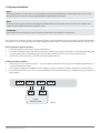
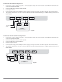
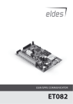
COMMUNICATOR
ET08
User Manual v1.0
Safety instructions
Please read and follow these safety guidelines in order to maintain safety of operators and people around:
•
•
•
•
•
•
•
GSM communicator (gateway) ET08 (further referenced as system or device) contains a radio transceiver operating in
GSM850/900/1800/1900 bands.
Don’t use the system where it can interfere with other devices and cause any potential danger.
Don’t use the system with medical devices if this is required in the manual of the medical device.
Don’t use the system in hazardous environment.
Don’t expose the system to high humidity, chemical environment or mechanical impacts.
Don’t attempt to personally repair the system.
System labelling sticker is at the bottom of the device.
System ET08 is a device mounted in limited access areas. Any system repairs must be done only by qualified, safety aware
personnel.
Mains power must be disconnected before any installation or tuning work starts. The system installation or maintenance
must not be done during stormy conditions.
The system must be powered by main 10-24V
dard and be easily accessible.
300mA power supply which must be approved by LST EN 60950-1 stan-
External power supply can be connected to AC mains only inside installation room with automatic 2-pole circuit breaker capable of disconnecting circuit in the event of short circuit or over-current condition.
Open circuit breaker must have a gap between connections of more
than 3mm.
Phase
Null
PE
AC 230V
50 Hz/DC 24V
ET08
USB cable
Any additional devices linked to the system ET08 (computer, sensors, relays etc.) must be approved by LST EN 60950-1
standard.
Fuse resettable F1 type - miniSMDC 500mA. Blown fuse cannot be replaced by the user and the replacement fuses have to
be exactly the same as indicated by the manufacturer.
If you use I security class computer for setting the parameters it must be connected to earth
ET08 can be powered direct from 12V battery. The battery capacity shouldn‘t be higher than 7Ah.
The WEEE (Waste Electrical and Electronic Equipment) marking on this product (see left) or its documentation indicates that in the EU
the product must not be disposed of together with household waste.
Copyright © “ELDES UAB”, 2011. All rights reserved.
It is strictly forbidden to copy and distribute information in this document or pass to a third party without an advanced written authorization from “ELDES
UAB”. “ELDES UAB” reserves the right to update or modify this document and/or related products without a warning. Hereby, ELDES UAB declares that this
COMMUNICATOR ET08 is in compliance with the essential requirements and other relevant provisions of Directive 1999/5/EC. The declaration of conformity may be consulted at www.eldes.lt.
Limited Liability
The buyer must agree that the system will reduce the risk of fire, theft, burglary or other dangers but does not guarantee against such events. “ELDES UAB” will not take any responsibility regarding
personal, property or revenue loss while using the
system. “ELDES UAB” responsibility according to
local laws does not exceed value of the purchased
system. “ELDES UAB” is not affiliated with GSM operators providing cellular services, therefore is not
responsible for network services, coverage or its
operation.
CONTENT
1 General Information......................................................................... 4
1.1 Function...........................................................................................................4
1.2 Operation Description................................................................................4
1.3 Technical Specifications ............................................................................5
1.4 Block Circuit ...................................................................................................5
1.5 Connectors Functionality..........................................................................5
1.6 Jumpers Functionality................................................................................6
1.7 LED Indicators Functionality.....................................................................6
1.8 System Installation.......................................................................................7
Manufacturer Warranty
2 System Pre-operation...................................................................... 9
The system carries a 24-month warranty by the
manufacturer “ELDES UAB”.
2.1 Operation Modes.................................................................................................9
2.1.1 Monitoring Station Mode.......................................................................9
2.1.2 SMS Messages Mode................................................................................9
2.1.3 Combined Monitoring Station Mode
and SMS Messages Mode........................................................................9
Warranty period starts from the day the system
has been purchased by the end user. The warranty
is valid only if the system has been used as intended, following all guidelines listed in the manual
and within specified operating conditions. Receipt
with purchase date must be kept as a proof.
The warranty is voided if the system has been
exposed to mechanical impacts, chemicals, high
humidity, fluids, corrosive and hazardous environment or other force majeure factors.
3 Appendix.........................................................................................10
3.1 Restoring Factory Default Parameters............................................... 10
3.2 ELDES “Configuration Tool” Program.................................................. 10
3.3 Technical Support...................................................................................... 10
Package Content
System ET08................................................................1 pcs
ET08 user manual......................................................1 pcs
GSM antenna..............................................................1 pcs
Fastening holders......................................................4 pcs
About User Manual. Quick Start.
This document describes communicator ET08, its operation and installation. It is very important to read User Manual before start
using the system. A quick start guide is located in first two chapters.
1. General Information
1.1 Function
Communicator ET08 is a device for transferring information from the Alarm Control Panel to the monitoring station via GSM
audio connection channel or/and users via SMS message.
The system can be used in the following applications:
•
Property security
•
Backup PSTN line using GSM network
1.2 Operation Description
ET08 provides a “dial tone” and fully replaces a telephone landline (PSTN) for Alarm Control Panel reporting to the central monitoring station when telephone line is unavailable or has been cut or disconnected by PSTN provider. ET08 supports only outgoing
calls. DTMF number dialling mode in alarm control panel must be enabled.
Can detect temporary service suspension by the service provider for technical or billing reasons even if a “dial tone” is still
present (Option available only for ET08B version).
Communicator ET08 backup function can work in 2 modes:
•
Backup Mode 1. ET08 is connected direct to PSTN landline.
If this mode is enabled the Alarm Control Panel's Ring&Tip contacts are switched direct to the PSTN landline and the
ET08 communicator just monitors the PSTN landline. In case of PSTN failure, ET08 "switches" the Alarm Control Panel's
Ring&Tip contacts to the GSM network and all communication goes to the Alarm receiving centre (ARC) through GSM
voice.
•
Backup Mode 2. ET08 is connected to PSTN landline via PBX station.
If this mode is enabled the Alarm Control Panel's Ring&Tip contacts are switched by ET08 direct to the PBX station
internal line. Then the signal initiated by the Alarm Control Panel for the Alarm Receiving Centre (ARC) is routed via the
PBX to an external PSTN landline. The ET08 communicator only monitors that the external PSTN landline is connected
to the PBX and does not monitor the internal line. In the case of external PSTN failure, the PBX still provides a dial tone
but ET08 "switches" the Alarm Control Panel's Ring&Tip contacts to the GSM network and all communication goes to
the ARC through GSM voice. This mode is used for sites where the internal telephone lines are sufficiently protected
by the alarm system but where it is impossible for the alarm system to protect the external PSTN landlines and ensure
they are connected to the PBX.
ET08 can operate in 3 communication modes, i.e.:
•
transmits information from the Alarm Control Panel to the monitoring station via GSM voice;
•
transmits information from the Alarm Control Panel only to the registered users via SMS message;
•
transmits information from the Alarm Control Panel to the monitoring station via GSM voice as well as to registered
users via SMS message.
A computer program ELDES “Configuration Tool” is used for configurations which are necessary for the system to operate in
the second and third modes, i.e., to send SMS messages to the registered users. The device is connected to the computer via USB
connection.
4
1.3 Technical Specifications
Electrical and Mechanical Specifications
Supply voltage
10-24V
Current used in standby mode
120mA max
300mA max
GSM modem frequency
850/900/1800/1900 MHz
Supported protocols
CONTACT ID, 4+2*
Maximum number of users to whom SMS messages are delivered
5
Dimensions
130x73 mm
Operating temperature range
-20...+55oC
Generated phone line voltage
18 V
Generated phone line current
25 mA
Generated phone line impedance
600 Ohm
Dial tone of generated phone line
350 Hz
* When SMS mode is enabled, system doesn‘t support 4+2 protocol. 4+2 protocol works only with Monitoring Station Mode.
1.4 Block Circuit
For configurations
DEFAULT
SIM CARD
GSM
MODEM
SET
MODE
PROG
ANT
USB
INFO
B1
STATUS
GSM
B2
FUSE
500 mA
L1 L2
L3
L4 RING TIP
N.C. DC+ COM
N.C. N.C. N.C.
1.5 Connectors Functionality
Connector Functionality
Main Units
GSM MODEM
GSM network
850/900/1800/1900 MHz
modem
Labelling
Explanation
DC+
Power supply positive connector
COM
Common contact
Pin connected to the Alarm Control Panel pin RING
SIM CARD
SIM card holder
RING
ANT
GSM antenna SMA type
connector
TIP
Pin connected to the Alarm Control Panel pins TIP
L1-L4
Pins connected to landline or PBX according back-up mode
Resettable F1 type – miniSMDC
500mA
USB
Mini USB port
N.C.
Not connected
FUSE
USER MANUAL ELDES ET08 V1.0
5
1.6 Jumpers Functionality
Labelling
Explanation
DEFAULT
Jumpers for restoring factory default settings
SET
Jumpers for enabling the 3rd operation mode of the device
MODE
Jumpers for connecting the 2nd operation mode of the device
PROG
Not used
B1 and B2
Jumpers for choosing GSM back-up operation mode
1.7 LED Indicators Functionality
Light Emitting Diodes LED
INFO
Working mode indicator
STATUS
Device activity indicator
GSM
GSM network quality indicator
Connection Strength Indicator
To identify connection strength GSM indicator is used. To ensure the best quality of the network adjust the position of GSM antenna and find the best possible connection by watching the frequency of indicator blinking.
GSM indicator blinking
Meaning
Off
No connection
Every 3 seconds
The connection is not reliable
Every second
Satisfactory
Several times per second
Good
Indicator is lit
Excellent
It is recommended to install the antenna remotely from communicator panel. Thus you will ensure better quality of audio signal.
We do not recommend installing the antenna in a metal box.
Device Activity Indication
STATUS indicator blinking
Meaning
Off
No power supply or some fault is present
Blinking several times per second
SIM card is used improperly/is not used
Indicator is lit
The device is working properly and ready for use
Working Mode Indication
INFO indicator blinking
Reikšmė
Off
The device is in passive mode
Blinking several times per second
The device retransmits the data sent from Security Control Panel to the panel of security service.
(this indication is possible then device is working
in first mode)
Indicator is lit
The device decodes the data sent via CONTACT
ID protocol to textual, user-understandable
information.
6
1.8 System Installation
NOTE
Due to GSM network characteristics it is recommended to use the system ET08 with the same GSM operator which is used
by system users. Thus you will ensure the quickest SMS message delivery and receipt.
NOTE
To ensure maximum system operation reliability we recommend do not use prepaid cards. If the balance is insufficient the
system will not be able to inform users about the alarm.
IMPORTANT:
power supply at Alarm Control Panel must be disconnected before any installation or tuning work.
The system can be installed in a metal or non-flammable plastic enclosure together with alarm control panel. When the metal box
is also used it is necessary to ground the box using yellow/green colour cable. For the connection use 0.50 mm2 1 thread cable.
Device installation and Pre-operation:
1.
Fasten the system in the enclosure using fastening holders.
2.
Place SIM card into the holder but make sure that SIM card PIN code is disabled. (PIN code can be disabled by putting SIM
card into mobile phone and following proper menus). SIM card should not have any remaining SMS messages.
3.
Connect the antenna (the device cannot be turned on without antenna).
For ET08 use with no landline:
1.
Connect the circuit as shown in Fig. No.2 – connect telephone input of the Alarm Control Panel RING/TIP to RING/TIP connectors of communicator ET08.
2.
Connect power supply to DC+/COM pins. Power supply is usually used as AUX- and AUX+ output of Alarm Control Panel.
3.
The system should start in less than a minute. GSM LED indicator should be blinking or be ON indicating connection to
GSM network.
L1 L2 L3
L4 RING TIP
RING/TIP
N.C. DC+ COM
AUX+ AUX-
ALARM
CONTROL PANEL
USER MANUAL ELDES ET08 V1.0
N.C. N.C. N.C.
Fig. No2
7
For ET08 use with landline backup mode 1:
1.
Connect the circuit as shown in Fig. No.3 – connect telephone input of the Alarm Control Panel RING/TIP to RING/TIP connectors of communicator ET08.
2.
Connect L3&L4 pins to external landline (PSTN).
3.
Put Jumpers B1 & B2.
4.
Connect power supply to DC+/COM pins. Power supply is usually used as AUX- and AUX+ output of Alarm Control Panel.
5.
The system should start in less than a minute. GSM LED indicator should be blinking or be ON indicating connection to
GSM network.
L1 L2 L3
N.C. DC+ COM
L4 RING TIP
To landline
(PSTN)
RING/TIP
N.C. N.C. N.C.
AUX+ AUX-
ALARM
CONTROL PANEL
Fig. No3
For ET08 use with PBX & landline backup mode 2:
1.
Connect the circuit as shown in Fig. No.4 – connect telephone input of the Alarm Control Panel RING/TIP to RING/TIP connectors of communicator ET08.
2.
Connect L1&L2 pins to external landline (PSTN).
3.
Connect L3&L4 pins to Internal PBX line.
4.
Remove Jumpers B1 & B2.
5.
Connect power supply to DC+/COM pins. Power supply is usually used as AUX- and AUX+ output of Alarm Control Panel.
6.
The system should start in less than a minute. GSM LED indicator should be blinking or be ON indicating connection to
GSM network.
L1 L2 L3
To landline
(PSTN)
PBX
Internal
Tel line
8
L4 RING TIP
N.C. DC+ COM
RING TIP
AUX+ AUX-
ALARM
CONTROL PANEL
N.C. N.C. N.C.
Fig. No 4
2. System Pre-operation
2.1Operation Modes
ET08 can operate in 3 modes, i.e.:
•
Transmits information from the Alarm Control Panel to the monitoring station via GSM voice;
•
Transmits information from the Alarm Control Panel only to the registered users via SMS message;
•
Transmits information from the Alarm Control Panel to the monitoring station via GSM voice as well as to registered users
via SMS message.
This chapter describes pre-operation and system operation when each of the above mentioned modes is enabled.
ATTENTION:
on the Alarm Control Panel you should enable tonal (DTMF) number dialling mode, activate CONTACT ID or 4+2 data transmission protocol and enter telephone number of Alarm receiving centre with geographic area or international code. Eg. For UK
London 020xxxxxxxx or 004420xxxxxxxx
ATTENTION:
it is also necessary to enter telephone number of security service on the Alarm Control Panel when you do not need to transmit
data to security service and you are using only SMS messaging mode. In such a case you can use any telephone number (you
can use the number consisting of one digit).
2.1.1 Monitoring Station Mode
If you want the device to operate in Monitoring station mode you must ensure that all Jumpers SET-MODEPROG are not used.
When this mode is enabled communicator ET08 only retransmits data sent from Alarm Control Panel via
CONTACT ID or 4+2 protocol to security service panel via GSM voice channel. ET08 does not require any
additional configurations.
SET
MODE
PROG
2.1.2 SMS Messages Mode
This operation mode is enabled by putting a jumper on MODE connectors in connector group SET-MODEPROG (as demonstrated in the example). Other connectors must not be short-circuited.
When this operation mode is used the information about the secured object is delivered only to user (users)
and alarm receiving centre is not informed. In this case ET08 decodes the data sent from the Alarm Control
Panel via CONTACT ID protocol to user-understandable text and sends it via SMS message. This decoding
is performed according to the preset parameters which can be specified by the user only by using the program ELDES “Configuration Tool” (for more information please refer to user manual of this program). SMS
messages can be received by up to 5 users.
SET
MODE
PROG
2.1.3 Combined Monitoring Station Mode and SMS Messages Mode
This operation mode is enabled by putting a jumper on SET connectors in connector group SET-MODEPROG (as demonstrated in the example). Other connectors must not be short-circuited.
When this operation mode is used the information about the secured object is received by the user (users)
as well as alarm receivig centre (ARC). Device retransmits the data sent from the Alarm Control Panel via
CONTACT ID protocol to the ARC and decodes this data to user-understandable text and sends it via SMS
message (indicator INFO informs only about decoding). The text is created by the user. This decoding is
performed according to the preset parameters which can be specified by the user only by using the program ELDES “Configuration Tool” (for more information please refer to user manual of this program). SMS
messages can be received by up to 5 users.
USER MANUAL ELDES ET08 V1.0
SET
MODE
PROG
9
3. Appendix
3.1 Restoring Factory Default Parameters
To restore factory default parameters:
•
disconnect power supply and USB from PC in case it was connected;
•
short circuit (connect) connectors DEFAULT;
•
connect power supply for 5 seconds;
•
disconnect power supply;
•
disconnect connectors DEFAULT.
3.2 ELDES “Configuration Tool” Program
System configuration is performed by using program software ELDES “Configuration Tool” that can be downloaded from internet
website www.eldes.lt
Before connecting the cable to the computer via USB port read ELDES “Configuration Tool” user manual that can be found in HELP
section of the program.
3.3 Technical Support
Indicator STATUS is off and not blinking
•
•
•
•
no external power supply
circuit not properly connected
blown fuse
no network signal
Indicator STATUS is blinking several times per second
•
•
•
SIM card is not inserted
SIM card PIN code request has not been disabled
SIM card not active
System does not deliver any SMS messages
•
•
•
•
•
SIM card account depleted
incorrect SMS central number
no network signal
user telephone number is not programmed in users list
user telephone number is indicated improperly (read more
about it in ET08 Configuration Tool user manual which can
be found in Help section of the program)
If your problem could not be fixed by the self-guide above, please contact your distributor or ELDES technical support by e-mail
[email protected]. More up to date information about your device and other products can be found at the manufacturer’s website
www.eldes.lt
10