1
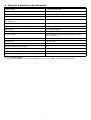
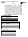
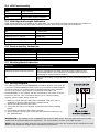
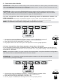
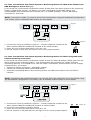
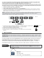
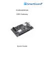
E18SGGSMGW
GSM Gateway
Quick Guide
1. Safety Instructions
Please read the following safety guidelines prior to installation.
• The SmartAccess GSM Gateway contains an integrated radio transceiver operating in GSM
850/900/1800/1900 MHz bands.
• Do not install the system where it can interfere with other devices or cause any potential danger.
• Do not mount the system next to medical equipment or medical devices.
• Do not use the system in hazardous environments.
• Do not expose the system to high humidity or in chemical environments.
• The system must only be installed by a qualified engineer.
• Any system repairs must be done only by qualified engineer.
• The system must be powered by 10-24V DC.
The WEEE (Waste Electrical and Electronic Equipment) marking on this product or its documentation
indicates that in the EU the product must not be disposed of together with household waste.
2. Function
The E18SGGSMGW is a device for transmitting data from alarm system to a monitoring station via:
• GSM audio channel
• Telehone landline (PSTN)
• GPRS network
It can also send an SMS message to the user.
3. Operation Description
The E18SGGSMGW communicator acts as a gateway between the alarm system and monitoring station
providing a dial tone and fully replacing the landline (PSTN). The communicator notifies the monitoring
station (E18SGGSMGW ONLY) and/or the user by SMS message in case PSTN is unavailable, has been
cut off or disconnected by PSTN provider. E18SGGSMGW supports only outgoing calls. DTMF number
dialling mode in the alarm system must be enabled.
The E18SGGSMGW features several communication paths between an alarm system and monitoring
station:
1.
2.
3.
4.
5.
6.
GSM audio channel;
PSTN using GSM audio channel as backup connection;
SMS messages to preset users;
PSTN using GSM audio channel as backup connection with data duplication to preset users via SMS;
GPRS network.
PSTN using GPRS network as backup connection.
Please, refer to section 6 (Communication Modes) for more details.
The E18SGGSMGW has 3 digital inputs (normally open) for sensor connection. The 3 open collector
outputs allow you to connect and control up to 3 electronic appliances on receipt of SMS text message(s)
from one of the pre-programmed phone numbers. This feature provides control of heating, lighting,
gates, blinds etc.
The SmartGuard Configuration Tool software is used to configure the system to operate in one of its
communication modes, providing data transmission either via SMS text message or via GPRS. The device
has to be connected to the computer using a USB cable. Please, refer to software‘s HELP section for
more details. This software can be downloaded from the Reliable Security Products Website—www.rspl.ie
2
4. Electrical & Mechanical Specifications
Power supply
10-24V 300 mA max
Current used in standby mode
120mA max
GSM modem frequency
850/900/1800/1900 MHz
Supported protocols
Contact ID, 4+2**
Maximum number of users to whom SMS messages 3
are delivered
Number of “low” level (negative) digital inputs*
3
Allowable input values*
Voltage: 0... 1.45V; current: 0.8... 0.6mA
Input type
NO (normally open)
Number of outputs*
3
Output circuit*
Open collector output. Output is pulled to COM
when turned on.
Maximum allowed output values*
Voltage: 30V ; current: 50 mA
Dimensions
130 x 73 mm
Operating temperature range
-20...+55°C
Generated phone line voltage
18 V
Generated phone line current
25 mA
Generated phone line impedance
600 Ω
Dial tone frequency of generated phone line
350 Hz
*only in E18SGGSMGW
**4+2 protocol operates in communication mode 1, 5 and 9 ONLY (via GSM audio channel).
3
5. Components, Connections, Pin & LED Functionality
Figure 1
5.1. Component Functionality
GSM MODEM
GSM network 850/900/1800/1900 MHz modem
SIM CARD
SIM card slot / holder
ANT
GSM antenna SMA type connector
F1
Fuse model – miniSMDC 500mA
USB
Mini USB port
5.2. Connector Functionality
Labelling
Description
L1 - L4
Landline or PBX contacts (according to backup mode)
RING
RING contact
TIP
TIP contact
C1 - C3
Outputs
DC+
Positive power supply contact
COM
Negative power supply contact / Common contact
Z1 - Z3
Inputs
N/A
Not available
5.3 Pin Functionality
Labelling
Description
DEF
For restoring factory default settings
SET
For enabling communication modes
MODE
For enabling communication modes
JP8, JP9
For communication backup connection
UART
Not Used
4
5.4 LED Functionality
Labelling
Description
INFO
Mode indicator
STATUS
Device activity indicator
GSM
GSM network quality indicator
5.5 GSM Signal Strength Indication
GSM signal strength is indicated by the GSM LED. To ensure best network signal adjust the position of
GSM antenna and find the strongest possible signal by observing the GSM LED indications.
GSM LED Indication
GSM Signal Strength
Off
No connection
Flashing every 3 seconds
The connection is not reliable
Flashing every 1 second
Satisfactory
Flashing several times per second
Good
On
Excellent
5.6 Device Activity Indication
STATUS LED Indication
Meaning
Off
No power supply or some fault is present
Flashing several times per second
SIM card is not inserted / inserted improperly
On
Device is operating and ready for use
5.7 Working Mode Indication
INFO LED
Indication Meaning
Off
Device is in standby mode
Flashing several times per second
Device retransmits the data sent from alarm system to the
monitoring station (this indication is possible when device is
operating in communication mode 1)
On
Device is decoding Contact ID data to user-understandable text
format
5.8 Wiring Diagram
The COM connectors of E18SGGSMGW and Alarm System unit must be
connected. E18SGGSMGW Inputs Z1-Z3 are connected to PGM outputs
of alarm system unit if PGM output is implemented as open collector
circuit or any other circuit and if it commutes with COM. The
E18SGGSMGW C1-C3 outputs can be connected to the inputs of other
electronic devices. This connection allows you to control heating,
lighting, gates, blinds, water pump etc.
Figure 2
1. Make sure that SIM card PIN code is disabled. PIN code can be
disabled by putting SIM card into a mobile phone
2. Insert the SIM card into the holder.
3. Terminate the Input and Output connections first before adding
power.
4. The system will start in less than a minute.
5. LED2 indicator should flash or will be ON indicating connection to
the GSM Network.
ATTENTION: The system is not compatible with pure 3G SIM cards. Only 2G SIM cards and 3G SIM
cards with 2G profile enabled are supported. For more details, contact your GSM operator.
NOTE: Pay-as-you-go SIM cards are not recommended for use with the system as an insufficient credit
balance will disable the system from transmitting information.
5
6. Communication Modes
ATTENTION: DTMF phone number dialling mode must be enabled on alarm system, activated Contact
ID or 4+2 data transmission protocol and monitoring station phone number set with international code,
i.e. 00353XXXXXXXX. Do not use the + character.
ATTENTION: Before connecting E18SGGSMGW power supply to alarm system‘s auxiliary output
(AUX), please ensure that the output is able to maintain peak current consumption of up to 700mA
max. Otherwise, please, use an external power supply for E18SGGSMGW.
6.1 Data Transmission from Alarm System to Monitoring Station via GSM Audio Channel - No
PSTN Connection
In this mode the communicator retransmits Contact ID or 4+2 data sent from alarm system to the
monitoring station via the GSM audio channel. There is NO backup connection for this mode.
NOTE: No additional communicator configuration is required for this mode.
Figure 3
Figure 4
1. Connect the circuit as indicated in Figure 3 above—connect telephone contacts of
the alarm system RING/TIP to RING/TIP contacts of the communicator.
2. Power the unit from the alarm panel +12V and –0V.
3. No jumpers have to be set on any pins. See Figure 4 for correct jumper position.
6.2 Data Transmission from Alarm System to Preset User (-s) by SMS
In this mode the communicator retransmits Contact ID data sent from alarm system and decodes it to
user-understandable text format which is sent to preset user (-s) by SMS message. There is NO backup
connection for this mode.
NOTE: User phone number (-s) must be set for the communicator using the SmartGuard Configuration
Tool. Please, refer to software's HELP section for more details.
ATTENTION: You must set a monitoring station phone number in the alarm system’s digital
communicator (one digit is enough).
Figure 5
Figure 6
1. Connect the circuit as indicated in Figure 5 – connect telephone contacts of the
alarm system RING/TIP to RING/TIP contacts of the communicator.
2. Power the unit from the alarm panel +12V and –0V.
3. Set the jumper on MODE pins. See Figure 6 for correct jumper position.
6
6.3 Data Transmission from Alarm System to Monitoring Station via GSM Audio Channel and
SMS Messages to Preset User (-s)
In this mode the communicator retransmits Contact ID data sent from alarm system to the monitoring
station via GSM audio channel. In addition, the data is duplicated and decoded data to userunderstandable text format and sent to preset user (-s) by SMS message. There is NO backup
connection for this mode.
NOTE: User phone number (-s) must be set for the communicator using the SmartGuard Configuration
Tool. Please, refer to software's HELP section for more details.
Figure 7
Figure 8
1. Connect the circuit as indicated in Figure 7 – connect telephone contacts of the
alarm system RING/TIP to RING/TIP contacts of the communicator.
2. Power the unit from the alarm panel +12V and –0V.
3. Set the jumper on SET pins. See Figure 8 for correct jumper position.
6.4 Data Transmission from Alarm System to Monitoring Station via PSTN using GSM Audio
Channel as Backup Connection
In this mode the communicator retransmits Contact ID and 4+2 data via landline (PSTN) sent from the
alarm system to the monitoring station. The communicator also monitors the voltage (dial tone
monitoring optional) on the PSTN and in case the PSTN is unavailable, disconnected or cut off (voltage
drops below 4V), the system:
• switches to backup connection – GSM audio channel,
• notifies the monitoring station about PSTN failure,
• continues transmitting data to the monitoring station via GSM audio channel until the PSTN is
restored.
NOTE: Notification about PSTN loss/restore (if required) has to be enabled for the communicator using
the SmartGuard Configuration Tool. Please, refer to software‘s HELP section for more details.
Figure 9
1. Connect the circuit as indicated in Figure 9 – connect telephone contacts of the
alarm system RING/TIP to RING/TIP contacts of communicator.
2. Connect L3/L4 contacts to landline (PSTN).
3. Power the unit from the alarm panel +12V and –0V.
4. Set the jumpers on JP8 and JP9 pins. See Figure 10 for correct jumper position.
7
Figure 10
6.5 Data Transmission from Alarm System to Monitoring Station via PSTN using GSM Audio
Channel as Backup Connection and SMS Messages to Preset User (-s)
In this mode the communicator retransmits Contact ID data via landline (PSTN) sent from alarm system
to monitoring station. The communicator also monitors the voltage (dial tone monitoring optional) on the
PSTN and in case the PSTN is unavailable, disconnected or cut off (voltage drops below 4V), the system:
• switches to backup connection – GSM audio channel,
• notifies monitoring station about PSTN failure,
• sends an SMS report to the preset user (-s) on PSTN failure,
• continues transmitting data to monitoring station via GSM audio channel until the PSTN is restored,
• duplicates and decodes data to user-understandable text format and sends it to preset user (-s) by
SMS message until the PSTN line is restored.
NOTE: User phone number (-s) must be set and notification about PSTN loss/restore (if required) has
to be enabled for the communicator using the SmartGuard Configuration Tool. Please, refer to
software‘s HELP section for more details. for more details.
Figure 11
1. Connect the circuit as indicated in Figure 11 – connect telephone contacts of the
alarm system RING/TIP to RING/TIP contacts of communicator.
2. Connect L3/L4 contacts to landline (PSTN).
3. Power the unit from the alarm panel +12V and –0V.
4. Set the jumpers on JP8, JP9 and SET pins. See Figure 12 for correct jumper
position.
Figure 12
7. SMS Commands
ATTENTION! In this user manual the underscore _ character represents one <space> character. There
must be no spaces or other characters at the beginning and at the end of the message. XXXX – 4-digit
SMS password.
In order to configure and control E18SGGSMGW system using SMS message, send the text command to
E18SGGSMGW SIM card phone number from one of the authorized phone numbers. The structure of
SMS message consists of 4-digit SMS password (the default SMS password is 0000 – four zeros), the
command and the parameters. For some commands the parameters are not applied, i.e. STATUS.
E18SGGSMGW notifies the user if a mistake was made in SMS command: “Command is not correct”.
Password
The 4-digit SMS password intended for system configuration and control via SMS
messages. Manufacturer default SMS password is 0000 (four zeros) which is
NECESSARY to change.
SMS Text:
0000_PSW_XXXX
Value: XXXX – new 4-digit password.
8
Status
The SMS report indicating information on system input and output status.
SMS Text:
XXXX_STATUS
Set User Phone
Number
The system supports up to 3 user phone numbers which can receive input alarm
and restore texts by SMS. User 1 phone number is mandatory while other phone
number entries are optional. All numbers must be entered starting with
international country code e.g. [country code][area code][local number]. Do not
use the plus (+) symbol.
SMS Text:
XXXX_NRx:[country code][area code][local number]
Value: NRx: - user phone number entry, range - [NR1... NR3]
Set Input
Alarm Text
Each input has an alarm text which is sent by SMS message to a preset user(-s)
in case the input is violated. Manufacturer default input alarm texts: Z1 - Input 1
TRIGGERED, Z2 - Input 2 TRIGGERED, Z3 - Input 3 TRIGGERED.
This command sets an alarm text for a specified input. Maximum allowed length
is 23 characters including space characters.
SMS Text:
XXXX_TZx:ON:NewAlarmText
Value: TZx - input number, range - [TZ1... TZ3].
Example: 1111_TZ3:ON:Sensor violated
Set Input
Restore Text
Each input has a restore text which is sent by SMS message to a preset user(-s)
in case the input is restored. Manufacturer default input alarm texts: Z1 - Input 1
RESTORED, Z2 - Input 2 RESTORED, Z3 - Input 3 RESTORED.
This command sets a restore text for a specified input. Maximum allowed length
is 23 characters including space characters.
SMS Text:
XXXX_TZx:OFF:NewAlarmText
Value: TZx - input number, range - [TZ1... TZ3].
Example: 1111_TZ3:OFF:Sensor restored
9
Disable Input
This command disables a specified input. By default, all inputs are enabled.
SMS Text:
XXXX_Zx:OFF
Value: Zx - input number, range - [Z1... Z3]
Example: 1111_Z3:OFF
Enable Input
This command enables a specified input.
SMS Text:
XXXX_Zx:ON
Value: Zx - input number, range - [Z1... Z3]
Example: 1111_Z1:ON
Set Output
Name
Each output has a name which is sent by SMS to a preset user (-s). Manufacturer
default output names: C1 - Output1, C2 - Output2, C3 - Output3.
This command sets at name for a specified output. Maximum allowed length is
23 characters.
SMS Text:
XXXX_TCx:NewOutputName
Value: TCx - output number, range - [TC1 ... TC3]
Example: 1111_TC2:Pump
Output ON
This function switches a specified output ON.
SMS Text:
XXXX_Cx:ON or XXXX_OutputName:ON
Value: Cx - output number, range - [C1 … C3]
10
Output OFF
This function switches a specified output OFF.
SMS Text:
XXXX_Cx:OFF or XXXX_OutputName:OFF
Value: Cx - output number, range - [C1 … C3]
Output Pulse
ON
This function switches a specified output ON for a set period of time and switches
the output back to OFF after the set period of time is over.
SMS Text:
XXXX_Cx:ON:T or XXXX_OutputName:ON:T
Value: T - period of time in seconds, range - [1-9999]
Output Pulse
OFF
This function switches a specified output OFF for a set period of time and
switches the output back to ON after the set period of time is over.
SMS Text:
XXXX_Cx:OFF:T or XXXX_OutputName:OFF:T
Value: T - period of time in seconds, range - [1-9999]
Telephone Line
Failure/Restore
Delay
The delay period of time between telephone line failure and restore events. If
telephone line failure and restore events occur before the set delay period of time
is over, the system will not send the SMS report.
SMS Text:
XXXX_TELDLY_T
Value: T - period of time in seconds, range - [1-250]
11
8. Appendix
8.1 Restoring Default Parameters
To restore the default parameters:
1. Disconnect the power supply;
2. Short circuit (connect) DEF pins;
3. Power up E18SGGSMGW for 7 seconds;
4. Disconnect the power supply;
5. Remove short circuit from DEF pins;
6. Parameters restored to default.
8.2 SmartGuard Configuration Tool Software
To configure the system, please install the configuration software, the SmartGuard Configuration Tool
which can be downloaded from www.rspl.ie. Before connecting USB cable to the computer, please, read
the SmartGuard Configuration Tool user guide available in the HELP section of the software.
8.3 Troubleshooting
Problem
Possible Reason
GSM LED is off or not flashing
•
•
•
•
STATUS LED flashing several times per
second
• SIM card not inserted / improperly inserted
• PIN code enabled
• SIM card inactive
System does not send any SMS
messages
•
•
•
•
Received SMS message “Incorrect
Format”
or “Command is not correct”
• Incorrect syntax
Extra <space> character is left in SMS message
No external power supply
Circuit not properly connected
Blown fuse
No GSM network signal
SIM card credit limit exceeded
Incorrect SMS centre phone number
No GSM network signal
User phone number is not preset.
12