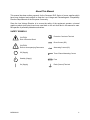
1
DHP Series
DC Power Supplies
Operation Manual
SORENSEN
Division of Elgar
9250 Brown Deer Road
San Diego, CA 92121-2294
1-800-733-5427
Tel: (858) 450-0085
Fax: (858) 458-0267
Email: [email protected]
www.elgar.com
©2002 by Sorensen, Division of Elgar Electronics Corporation
This document contains information proprietary to Sorensen, division of Elgar Electronics Corporation. The information
contained herein is not to be duplicated or transferred in any manner without prior written permission from Sorensen.
September 12, 2002
Document No. M550004-01 Rev C
Safety Notice
Before applying power to the system, verify that the unit is configured properly for the user's
particular application.
CE and UL recognition status of this series of power supplies is based on rack mounted
application only. Use of the power supplies outside of a rack mount enclosure will expose the
user to high voltage and/or high current sources. Extreme caution must be used under these
circumstances.
The analog control inputs (connectors J1 and J2) on the rear panel are referenced to the
negative output of the power supply. Grounding the positive output of the power supply or
biasing the output of the supply above chassis potential will cause these inputs (along with the
output of the supply) to have a potentially hazardous offset voltage. Exercise caution under
these conditions. Under no circumstances should the output of the supply be biased more than
500 volts from chassis potential.
Installation and service must be performed only by properly trained and
qualified personnel who are aware of dealing with attendant hazards. This
includes simple tasks such as fuse verification.
Ensure that the AC power line ground is connected properly to the unit
input connector or chassis. Similarly, other power ground lines including
those to application maintenance equipment must be grounded properly
for both personnel and equipment safety.
Always ensure that facility AC input power is de-energized prior to connecting or disconnecting
the input/output power cables.
Warning:
Lethal voltages may be present inside the power supply even when the AC input
voltage is disconnected. Only properly trained and qualified personnel should
remove covers and access the inside of the power supply.
During normal operation, the operator does not have access to hazardous voltages within the
chassis. However, depending on the user's application configuration, HIGH VOLTAGES
HAZARDOUS TO HUMAN SAFETY may be generated normally on the output terminals.
Ensure that the output power lines are labeled properly as to the safety hazards and that any
inadvertent contact with hazardous voltages is eliminated.
Due to filtering, the unit has high leakage current to the chassis. Therefore, it is essential to
operate this unit with a safety ground.
This unit is designed to be permanently connected to the power source and as such must have
a readily accessible disconnect device incorporated in the fixed wiring.
After the unit has been operating for some time, the metal near the rear of the unit may be hot
enough to cause injury. Let the unit cool before handling.
These operating instructions form an integral part of the equipment and must be available to the
operating personnel at all times. All the safety instructions and advice notes are to be followed.
Neither Sorensen nor any of the subsidiary sales organizations can accept responsibility for
personal, material or consequential injury, loss or damage that results from improper use of the
equipment and accessories.
M550004-01
i
SERVICE SAFETY NOTICES
WARNING!
Hazardous voltages in excess of 480 V RMS,
700 V peak may be present when covers are
removed.
Qualified personnel must use
extreme caution when servicing this equipment.
Circuit boards, test points, and output voltages
may be floating above chassis ground.
WARNING!
To guard against risk of electrical shock during
open cover checks, do no touch any portion of
the electrical circuits. Even when the power is
off, capacitors can retain an electrical charge.
Use safety glasses during open cover checks to
avoid personal injury by any sudden failure of a
component.
WARNING!
Some circuits are live even with the front panel
switch turned off. Service, fuse verification,
and connection of wiring to the chassis must be
accomplished at least five minutes after power
has been removed via external means; all
circuits and/or terminals to be touched must be
safety grounded to the chassis.
WARNING!
Qualified service personnel need to be aware
that some heat sinks are not necessarily at
ground, but at high potential.
WARNING!
Under no condition should the negative output
terminal exceed 150 volts, positive or negative,
from chassis potential.
M550004-01
ii
FCC NOTICE
This equipment has been tested and found to
comply with the limits for a Class A digital device,
pursuant to part 15 of the FCC Rules. These limits
are designed to provide reasonable protection
against harmful interference when the equipment is
operated in a commercial environment.
This
equipment generates, uses, and can radiate radio
frequency energy and, if not installed and used in
accordance with the instruction manual, may cause
harmful interference to radio communications.
Operation of this equipment in a residential area is
likely to cause harmful interference in which case
the user will be required to correct the interference
at his own expense.
M550004-01
iii
About This Manual
This manual has been written expressly for the Sorensen DHP Series of power supplies which
have been designed and certified to meet the Low Voltage and Electromagnetic Compatibility
Directive Requirements of the European Community.
Since the Low Voltage Directive is to ensure the safety of the equipment operator, universal
graphic symbols (see below) have been used both on the unit itself and in this manual to warn
the operator of potentially hazardous situations.
SAFETY SYMBOLS
CAUTION
Risk of Electrical Shock
Protective Conductor Terminal
Direct Current (DC)
CAUTION
Refer to Accompanying Documents
Off (Supply)
M550004-01
Alternating Current (AC)
Three–Phase Alternating Current
Standby (Supply)
Fuse
On (Supply)
Earth (Ground) Terminal
iv
TABLE OF CONTENTS
Chapter 1 DESCRIPTION OF EQUIPMENT ......................................................................... 1-1
1.1
PURPOSE AND CAPABILITIES ________________________________________ 1-1
1.2
TECHNICAL CHARACTERISTICS ______________________________________ 1-1
Chapter 2 INSTALLATION.......................................................................................................... 2-1
2.1
INSPECTION_______________________________________________________ 2-1
2.2
INPUT/OUTPUT CONNECTORS _______________________________________ 2-1
2.3
LOCATION AND MOUNTING __________________________________________ 2-1
2.4
WIRE SIZING ______________________________________________________ 2-4
2.5
OUTLINE DRAWINGS _______________________________________________ 2-4
Chapter 3 OPERATING INSTRUCTIONS.............................................................................. 3-1
3.1
CONTROLS AND INDICATORS ________________________________________ 3-1
3.2
BASIC OPERATION _________________________________________________ 3-2
3.3
LOCAL OPERATION_________________________________________________ 3-8
3.4
REMOTE CURRENT PROGRAMMING __________________________________ 3-8
3.5
REMOTE VOLTAGE PROGRAMMING __________________________________ 3-9
3.6
REMOTE SENSING _________________________________________________ 3-9
3.7
REMOTE OUTPUT ON/OFF CONTROL ________________________________ 3-10
3.8
REMOTE OVERVOLTAGE SET _______________________________________ 3-10
Chapter 4 AUTO-STEP PROGRAMMING ............................................................................. 4-1
4.1
INTRODUCTION ____________________________________________________ 4-1
4.2
PROGRAMMING____________________________________________________ 4-1
4.3
RUNNING A PROGRAM ______________________________________________ 4-4
Chapter 5 CALIBRATION.......................................................................................................... 5-1
5.1
INTRODUCTION ____________________________________________________ 5-1
5.2
REQUIRED EQUIPMENT _____________________________________________ 5-1
5.3
CALIBRATION PROCEDURE__________________________________________ 5-1
Chapter 6 MAINTENANCE ....................................................................................................... 6-1
6.1
INTRODUCTION ____________________________________________________ 6-1
6.2
PREVENTIVE MAINTENANCE_________________________________________ 6-1
M550004-01
v
LIST OF FIGURES
Figure 2-1 Outline Drawing, 2kW to 3kW (Output Voltage <=60 V)...........................................2-5
Figure 2-2 Outline Drawing, 2kW to 3kW (Output Voltage >=80 V)...........................................2-6
Figure 2-3 Outline Drawing, 3.3kW to 15kW (Output Voltage <=60 V)......................................2-7
Figure 2-4 Outline Drawing, 3.3kW to 15kW (Output Voltage >=80 V)......................................2-8
Figure 2-5 Outline Drawing, 13.3kW & 16kW to 30kW (Output Voltage <=60 V) ......................2-9
Figure 2-6 Outline Drawing, 13.3kW & 16kW to 30kW (Output Voltage >=80 V) ....................2-10
Figure 3-1 DHP Series Controls and Indicators.........................................................................3-1
Figure 3-2 Pin-out for Connector J1...........................................................................................3-8
Figure 3-3 Remote Current Programming Using Resistance ..................................................3-11
Figure 3-4 Remote Current Programming Using 0-5 or 0-10 VDC Source..............................3-11
Figure 3-5 Remote Voltage Programming Using Resistance ..................................................3-12
Figure 3-6 Remote Voltage Programming Using 0-5 or 0-10 VDC Source .............................3-12
Figure 3-7a Remote Sensing Operation at the Load ...............................................................3-13
Figure 3-8b Remote Sensing Operation at the Load ≤ 60V Out ..............................................3-13
Figure 3-9 Remote On/Off Control by Contact Closure ...........................................................3-14
Figure 3-10 Remote On/Off Using Isolated AC or DC Voltage Source....................................3-14
Figure 3-11 Remote On/Off Using Isolated TTL/CMOS Voltage Supply .................................3-15
Figure 3-12 Remote Overvoltage Set Using DC Voltage Source ............................................3-15
Figure 4-1 Auto-step Programming Screen ...............................................................................4-1
Figure 4-2 Auto-step Programming Menu System.....................................................................4-2
Figure 4-3 Programming Start Screen .......................................................................................4-3
Figure 4-4 Control Source Menu................................................................................................4-4
Figure 4-5 Control Source – Auto-step ......................................................................................4-4
Figure 4-6 Auto-step Activation Screen .....................................................................................4-4
Figure 5-1 Power Supply Calibration Screen.............................................................................5-1
Figure 5-2 Calibration Abort Screen ..........................................................................................5-2
Figure 5-3 Prepare Shunt Screen ..............................................................................................5-2
Figure 5-4 Current Calibration 1 ................................................................................................5-2
Figure 5-5 Hot Shunt Warning Screen.......................................................................................5-3
Figure 5-6 Current Calibration 2 ................................................................................................5-3
Figure 5-7 Prepare Load Screen ...............................................................................................5-4
Figure 5-8 Voltage Calibration 1 ................................................................................................5-4
Figure 5-9 High Voltage Warning Screen ..................................................................................5-4
Figure 5-10 Voltage Calibration 2 ..............................................................................................5-5
Figure 5-11 Accept Calibration Screen ......................................................................................5-5
LIST OF TABLES
Table 1-1 2 kW to 3 kW Series Technical Characteristics .........................................................1-2
Table 1-2 5kW to 15kW and 16kW to 30kW Series Technical Characteristics..........................1-4
Table 1-3 Available Voltages and Currents ...............................................................................1-6
Table 2-1 2kW to 3kW High Series Input/Output Connectors....................................................2-2
Table 2-2 5kW to 15kW and 16kW to 30kW Series Input/Output Connectors...........................2-2
Table 2-3 Output Connection Descriptions*...............................................................................2-3
Table 2-4 Input Connection Descriptions...................................................................................2-3
Table 2-5 Minimum Wire SizeTable...........................................................................................2-4
Table 3-1 2U, 3U and 6U High Series Controls and Indicators .................................................3-1
Table 3-2 J1 Designations and Functions..................................................................................3-6
Table 6-1 Preventive Maintenance Schedule ............................................................................6-1
Table 6-2 Inspection and Corrective Action ...............................................................................6-2
M550004-01
vi
Chapter 1
DESCRIPTION OF EQUIPMENT
1.1
PURPOSE AND CAPABILITIES
The Sorensen DHP Series power supplies are general purpose power supplies designed
specifically for laboratory test and systems applications requiring variable DC sources
with good ripple and regulation characteristics. The DHP power supplies include three
separate series: the 2U High, the 3U High and the 6U High. The power supplies of each
series are constant current/constant voltage supplies with an automatic crossover
feature. The 2U High Series models provide up to 3000 watts, the 3U High models up to
15 kilowatts, and the 6U High models up to 30 kilowatts, each over a wide range of
voltage and current levels.
1.2
TECHNICAL CHARACTERISTICS
The physical, electrical, and environmental characteristics for the 2U, 3U and 6U High
Series are listed in Tables 1-1 through 1-3.
M550004-01
1-1
Table 1-1
2 kW to 3 kW Series Technical Characteristics
PARAMETERS
PHYSICAL CHARACTERISTICS
Width
Depth
Height
Weight
ELECTRICAL CHARACTERISTICS
Input Power (Standard)
Voltage
SPECIFICATIONS
19.00 in.
18.00 in (output connections not included)
3.50 in.
45 lbs. max.
208-230 VAC
(tested to 190-253 VAC)
Frequency
47 to 63 Hz
Phases
Single, 2-wire plus ground
Three, 3-wire plus ground (optional)
Regulation (Line or Load)
Voltage
Current
0.1% of max. output voltage
0.1% of max. output current
Transient Response
A 30% step load will recover to within 2% of
original value within 10ms.
Stability
+0.05% of set point after 8 hr. warm-up
at fixed line, load and temp.
Remote Control/Monitor
Output On/Off control via contact closure,
6-120 VDC or 12-120 VAC, and TTL or CMOS
switch, output voltage and current monitor,
OVP limit set, and summary fault status
Power Density
2.5 Watts/cubic in.
Power Factor
.72 min.
Efficiency
80% minimum at full load
M550004-01
1-2
Table 1-1
2 kW to 3 kW High Series Technical Characteristics – Continued
PARAMETERS
SPECIFICATIONS
REMOTE PROGRAMMING
Resistive:
Constant Voltage (0-100%)
Constant Current (0-100%)
0 - 5k ohms
0 - 5k ohms
Voltage:
Constant Voltage (0-100%)
Constant Current (0-100%)
0 - 5/10 VDC
0 - 5/10 VDC
Remote Sensing
ENVIRONMENTAL CHARACTERISTICS
Temperature Coefficient
Terminals are provided to sense output voltage
at point of load. Maximum line drop
3% of rated voltage per line, or 2 volts,
whichever is less.
0.02%/°C of max. output voltage rating for
voltage set point.
0.03%/°C of max. output current rating for
current set point.
Ambient Temperature
Operating
Storage
0 to 50°C
-40° to 75°C
Humidity
0-80% RH, non-condensing
Cooling
Internal fans
Agency Approvals (excludes 600 volt
models)
TÜV NRTL to UL1950
TÜV to IEC 950
CE mark
M550004-01
1-3
Table 1-2
5kW to 15kW and 16kW to 30kW Series Technical Characteristics
PARAMETERS
PHYSICAL CHARACTERISTICS
Width
Depth
Height
Weight
ELECTRICAL CHARACTERISTICS
Input Power
Voltage
Standard
Options
SPECIFICATIONS
≤60V to 10kW
≤60V to 20kW
≥80V to 15kW
≥80V to 30kW
600V to 10kW
600V to 20kW
19.00 in.
19.00 in.
22.00 in.
22.00 in.
(output connections not included)
5.25 in.
10.5 in.
120 lbs. max.
163 lbs. max.
208-230 VAC (tested to 190-253 VAC)
400 VAC (tested to 360-440 VAC)
480 VAC (tested to 432-528 VAC)
Frequency
47 to 63 Hz
Phases
3-phase, 3-wire plus ground
Regulation (Line or Load)
Voltage
Current
0.1% of max. output voltage
0.1% of max. output current for 80V and higher
0.5% of max. output current for <80V
Transient Response
A 30% step load will recover to within 2% of
original value within 10ms.
Stability
+0.05% of set point after 8 hr. warm-up
at fixed line, load and temp.
Remote Control/Monitor
On/Off control via contact closure, 6-120
VDC or 12-120 VAC, and TTL or CMOS
switch, output voltage and current monitor,
OVP limit set, summary fault status.
Power Density
Power Factor
Efficiency
M550004-01
4.5 Watts/cubic in. (10 & 20 KW)
6.8 Watts/cubic in. (15 & 30 KW)
.72 min.
80% minimum at full load
1-4
Table 1-2
5kW to 15kW and 16kW to 30kW Series Technical Characteristics - Continued
PARAMETERS
REMOTE PROGRAMMING
Resistive
Constant Voltage (0-100%)
Constant Current (0-100%)
Voltage
Constant Voltage (0-100%)
Constant Current (0-100%)
Remote Sensing
ENVIRONMENTAL CHARACTERISTICS
Temperature Coefficient
SPECIFICATIONS
0 - 5k ohms
0 - 5k ohms
0 - 5 VDC or 0 -10 VDC
0 - 5 VDC or 0 -10 VDC
Terminals are provided to sense output voltage
at point of load. Maximum line drop, 3% of
rated voltage per line, or 2 volts, whichever is
less.
0.02%/°C of max. output voltage rating for
voltage set point.
0.03%/°C of max. output current rating for
current set point.
Ambient Temperature
Operating
Storage
0 to 50°C
-40° to 75°C
Humidity
0-80% RH, non condensing
Cooling
Internal fans
Agency Approvals (excludes 600 volt
models)
TÜV NRTL to UL1950
TÜV to IEC 950
CE mark
M550004-01
1-5
Table 1-3
Available Voltages and Currents
2U HEIGHT
V Out
2KW
5
325
3KW
3U HEIGHT
5KW
6U HEIGHT
6.6KW
10KW
15KW
13.3KW 16.6KW
1000
1500
2000
2500
20KW
3000
8
250
350
800
1200
10
200
300
660
1000
1600
1300
2000
1650
2400
2000
530
800
1060
1325
1600
12.5
15
130
200
440
660
880
1100
1320
20
100
150
330
500
665
830
1000
265
400
520
650
800
25
25KW
30KW
30
66
100
220
330
440
550
660
40
50
75
166
250
330
415
500
50
40
60
133
200
265
330
400
60
33
50
110
166
220
275
330
80
25
37
62
125
187
250
312
375
100
20
30
50
100
150
200
250
300
120
16
25
38
76
115
153
192
230
150
13
20
33
66
100
133
166
200
200
10
15
25
50
75
100
125
150
250
8
12
20
40
60
80
100
120
300
6.6
10
16
33
50
66
83
100
400
5
7.5
12
25
37
50
62
75
130
600
11
16
22
27
33
Output Ripple - Typical
Notes:
RATING
P-P
RMS
voltage and current from
5-15V
30 mV
10-15 mV
from table, e.g.
20-60V
45 mV
15 mV
80V
100 mV
25 mV
100V
125 mV
25 mV
120V
135 mV
25 mV
150V
150 mV
25 mV
200V
175 mV
25 mV
250-300V
200 mV
25 mV
400V
225 mV
25 mV
600V
2V
250 mV
- Basic model number includes
DHP5-325
VOLTS
CURRENT
- 600 volt models are not CE
marked or UL listed.
M550004-01
1-6
Chapter 2
INSTALLATION
2.1
INSPECTION
Inspect the shipping carton for possible damage before unpacking the unit. Carefully
unpack the equipment. Save all packing materials until inspection is complete. Verify
that all items listed on the packing slips have been received. Visually inspect all exterior
surfaces for broken knobs, connectors, or meters. Inspect for dented or damaged
exterior surfaces. External damage may be an indication of internal damage. If any
damage is evident, immediately contact the carrier that delivered the unit and submit a
damage report. Failure to do so could invalidate future claims.
2.2
INPUT/OUTPUT CONNECTORS
Tables 2-1 and 2-2 list all external connections for the 2U, 3U and 6U High Series
models, respectively. Tables 2-3 and 2-4 provide input and output connector
descriptions.
For permanently connected equipment, a readily accessible disconnect device shall be
incorporated in the fixed wiring. For plugable equipment, the socket outlet shall be
installed near the equipment and shall be easily accessible.
Take precautions to ensure that the concentration of ozone is limited to a safe value.
The recommended long-term exposure limit for ozone is 0.1 PPM (0.2 mg/m3).
NOTICE
For proper connection to the mains, a
100 amp or less circuit breaker or fuse
is required.
2.3
LOCATION AND MOUNTING
The DHP Series models are intended for mounting in a standard 19.0-inch equipment
rack. Four screws, two on each side of the front panel, should be used to secure the
unit in place.
NOTICE
The unit should be provided with
proper ventilation. The top, rear and
both sides of the unit should be free of
obstructions.
M550004-01
2-1
Follow the instructions in paragraph 3-2 for setup and operation of the equipment.
Table 2-1
2kW to 3kW High Series Input/Output Connectors
CONNECTOR
FL1 - AC
FL1 – AC
FL1-AC
CHASSIS - GND
Pos. Bus Bar
Neg. Bus Bar
Pos. Threaded Stud
Neg. Threaded Stud
(>=80V)
FUNCTION
Prime Power Input
(Std)
(with opt. 3 phase)
190-253 VAC (Std)
47-63 Hz
Power Source
Output Power
(see Table 2-3)
User load(s)
(see Table 2-3)
Control Interface
J1
CONNECTS TO
See Table 3-2 for
description
Table 2-2
5kW to 15kW and 16kW to 30kW Series Input/Output Connectors
CONNECTOR
FL1 - AC
FL1 - AC
FL1 - AC
CHASSIS - GND
FUNCTION
Prime Power Input
(Std)
CONNECTS TO
200-240 VAC (Std)
47-63 Hz
360-440 VAC (option)
432-528 VAC (option)
Output Power
User load(s)
Pos. Bus Bar
Neg. Bus Bar
(<=60V)
(see Table 2-3)
Pos. Threaded Stud
Neg. Threaded Stud
(>=80V)
(see Table 2-3)
J1
M550004-01
Control Interface
See Table 3-2 for a
Description
2-2
Table 2-3
Output Connection Descriptions*
SUPPLY TYPE
*
CONNECTION DESCRIPTION
2kW to 3kW
<=60V
Bus Bar with hole for 3/8” bolt
6.6kW to 10kW
<=60V
Bus Bar with two holes for 3/8” bolts
13.3kW to 20kW
<=60V
Bus Bar with three holes for 3/8” bolts
2kW to 3kW
>=80V
Terminal Block with 10-32 screws
5kW to 15kW
>=80V
3/8” Threaded Studs
16kW to 30kW
>=80V
3/8” Threaded Studs
Under no condition should the negative output terminal exceed 150 volts, positive or
negative, from chassis potential.
Table 2-4
Input Connection Descriptions
SUPPLY TYPE
CONNECTION DESCRIPTION
2kW to 3kW
10-32 Threaded Studs
5kW to 30kW
3/8” Threaded Studs
Note: Observe the maximum torque specification indicated on the cover.
M550004-01
2-3
2.4
WIRE SIZING
Care must be taken to properly size all conductors for the input and output of the power
supply. Table 2-5 below gives minimum recommended wire size for the input. This
table is derived from the National Electrical Code and is for reference only. Local laws
and conditions may have different requirements. The table is for copper wire only.
Table 2-5
Minimum Wire SizeTable
SIZE
AWG
MCM
14
12
10
8
6
4
3
2
1
0
00
000
0000
TEMPERATURE RATING OF COPPER CONDUCTOR
60 °C
75 °C
85 °C
90 °C
TYPES
TYPES
TYPES
TYPES
V, MI
TA, TBS, SA,
RUW, T, TW, FEPW, RH,
AVB, SIS, FEP,
UF
RHW, RUH,
FEPB, RHH,
THW, THWN,
THHN, XHHW
XHHW, USE,
ZW
CURRENT RATING
20
20
25
25
25
25
30
30
30
35
40
40
40
50
55
55
55
65
70
75
70
85
95
95
85
100
110
110
95
115
125
130
110
130
145
150
125
150
165
170
145
175
190
195
165
200
215
225
195
230
250
260
For higher ratings wires can be paralleled or refer to the National Electrical Code.
2.5
OUTLINE DRAWINGS
The following pages (figures 2-1 through 2-6) show the outlines and overall dimensions
for the DHP product lines.
M550004-01
2-4
J1
J3
NEG
POS
J2
DC OUTPUT
REMOTE
REMOTE
PROGRAM
PROGRAM
IEEE ADDRESS
AC CONTROL
STATUS
DC CONTROL
CONSTANT VOLTAGE
CONSTANT CURRENT
MENU
CONSTANT POWER
LAST SET
REMOTE
3
1
2
4
5
6
7
.
8
9
ENTER
0
Figure 2-1
Outline Drawing, 2kW to 3kW (Output Voltage <=60 V)
M550004-01
2-5
J1
J3
POS
NEG
J2
DC OUTPUT
REMOTE
REMOTE
PROGRAM
PROGRAM
IEEE ADDRESS
AC CONTROL
STATUS
DC CONTROL
CONSTANT VOLTAGE
CONSTANT CURRENT
MENU
CONSTANT POWER
LAST SET
REMOTE
1
2
3
4
5
6
7
.
8
9
ENTER
0
Figure 2-2
Outline Drawing, 2kW to 3kW (Output Voltage >=80 V)
M550004-01
2-6
AC CONTROL
STATUS
DC CONTROL
CONSTANT VOLTAGE
CONSTANT CURRENT
MENU
CONSTANT POWER
LAST SET
REMOTE
1
2
3
4
5
6
7
.
8
9
ENTER
0
Figure 2-3
Outline Drawing, 3.3kW to 15kW (Output Voltage <=60 V)
M550004-01
2-7
AC CONTROL
STATUS
DC CONTROL
CONSTANT VOLTAGE
CONSTANT CURRENT
MENU
CONSTANT POWER
LAST SET
REMOTE
1
2
3
4
5
6
7
.
8
9
ENTER
0
Figure 2-4
Outline Drawing, 3.3kW to 15kW (Output Voltage >=80 V)
M550004-01
2-8
AC CONTROL
STATUS
DC CONTROL
CONTSTANT VOLTAGE
CONTSTANT CURRENT
MENU
CONTSTANT POWER
LAST SET
REMOTE
1
2
3
4
5
6
7
.
8
9
ENTER
0
Figure 2-5
Outline Drawing, 13.3kW & 16kW to 30kW (Output Voltage <=60 V)
M550004-01
2-9
AC CONTROL
STATUS
DC CONTROL
CONTSTANT VOLTAGE
CONTSTANT CURRENT
1
MENU
CONTSTANT POWER
LAST SET
REMOTE
2
3
4
5
6
7
.
8
9
ENTER
0
Figure 2-6
Outline Drawing, 13.3kW & 16kW to 30kW (Output Voltage >=80 V)
M550004-01
2-10
Chapter 3
OPERATING INSTRUCTIONS
3.1
CONTROLS AND INDICATORS
Front panel controls and indicators for the DHP Series are identified in Figure 3-1.
Although different models may have different heights, the controls remain the same
across the entire series. Table 3-1 provides a description of all operator controls and
indicators.
1
3
2
4
CONSTANT VOLTAGE
OFF
OUTPUT:
10.00 VOLTS
100 AMPS
CONSTANT CURRENT
MENU
3
1
2
4
5
7
.
8
9
0
CANCEL
VOLTAGE
ON
6
CURRENT
CONSTANT POWER
REMOTE
LAST SET
OVERVOLT
ENTER
Figure 3-1
DHP Series Controls and Indicators
Table 3-1
2U, 3U and 6U High Series Controls and Indicators
INDEX NO.
CONTROL/INDICATOR
FUNCTION
1
ON/OFF Switch
Turns power on or off to the supply.
Note: Standby power is present when
switch is in the off position.
2
Alphanumeric Display
Displays output voltage and current,
power supply status and other
information.
3
Status Displays
Display operating mode of power
supply.
4
Control Keyboard
Allows user control of power supply.
M550004-01
3-1
3.2
BASIC OPERATION
The following section describes the basic operation of the power supply including the
use of most keyboard functions and the related displays.
ACTION / PROCEDURE
DISPLAY
Turn power switch to ON
INITIALIZING The Model Number is identified and initialization begins. Initializing
consists of internal diagnostics and self-calibration of control boards.
OUTPUT After initialization, the Output is displayed.
Note that the voltage and current settings read “0”,
unless it is in the remote mode. The “0” reading
indicates no output on the terminals at the rear of the supply.
MODEL NUMBER AND RATINGS
Displayed by pressing and holding down the ▼
(down) key when the Output is displayed.
LIMIT SETTINGS Displayed by pressing and holding
down the ▲ (up) key when the output screen is
displayed. The output settings displayed are those
applied at the output terminals.
LAST SET retrieves and displays the last voltage and current settings applied to the
output terminals and it applies these settings to the output terminals.
WARNING
LAST SET applies the last voltage and
current settings to the output terminals.
Hazardous voltage levels that could cause
shock and be lethal may be present at the
terminals.
SET VOLTAGE LIMIT To set the output voltage
limit, press the Voltage button, then enter a limit
from the keypad or, using the ▲ ▼ keys, scroll to
desired limit. Press ENTER to set limit.
SET CURRENT LIMIT To set the current limit,
press the Current button, then enter a limit from
M550004-01
3-2
keypad or, using the ▲ ▼ keys, scroll to desired limit. Press ENTER to set limit.
SET OVERVOLTAGE Press overvoltage button,
then enter limit from keypad or, using the ▲ ▼ keys,
scroll to desired limit. Press ENTER to set limit.
MENU BUTTON Use the menu button to access advanced functions of the power
supply. Cycle through the main menu by pressing and releasing the MENU button. The
following list describes the functions in the main menu.
Restore From Memory
Save to Memory
Control Source
Set Power Limit
Auto-step Programming
SCPI Control Options (Optional)
Analog Control Options
INT Data:
Power Supply Calibration
RESTORE FROM MEMORY There are nine
memory locations (1-9) from which stored data can
be retrieved (After data has been saved in them).
To access a memory location, cycle the MENU
button to the Restore From Memory mode, enter the desired memory location from the
keypad or scroll to the location using the ▲ ▼ keys. Once the desired location is
selected, press ENTER to retrieve the settings. Upon their retrieval, the settings are
applied to the output terminals. To verify that retrieved settings are at the output
terminals, cycle the MENU button until the output screen is displayed and press the ▲
arrow key (See Limit Settings above).
WARNING
Restoring from memory immediately applies
the new voltage and current settings to the
output terminals. Hazardous voltage levels
may be present at the terminals.
SAVE TO MEMORY There are nine memory
locations (1-9) where voltage and current settings
can be saved for future retrieval and use. This
function saves the present voltage, current,
overvoltage and control source settings into one of the nine memories. The memory
location appears immediately after the function title, Save To Memory.
M550004-01
3-3
Cycle the MENU button to Save To Memory and select a memory location by entering it
from the key pad or by scrolling to it using the ▲ ▼ keys. Once selected, press ENTER
and all current settings will be saved.
CONTROL SOURCE The control source for the
power supply is the location from which the output of
the power supply can be controlled. To select the
control source for the power supply, cycle to the Control Source function, and then use
the bc keys to scroll through the eight programming modes. The four modes are listed
below.
KEYBOARD All control is from the keyboard.
REM ANALOG This mode allows an analog remote source connected to the power
supply at the input connector J1 on the rear panel to control the power supply. This
control mode enables the remote source to control either the voltage limit or the
current limit, or both with a 0-5 volt or 0-10 volt or 0-5,000 ohm signal. Selection of
what is controlled and how is done via the ANALOG CONTROL OPTIONS MENU
explained later in this section.
SCPI (Optional) Control is passed to the SCPI interface. For use please refer to the
SCPI Option User’s Manual.
AUTO-STEP Control is passed to the auto-step program. Instructions on how to
set up the program are in Auto-step Programming Section of this manual.
ANALOG CONTROL OPTION: When REM
ANALOG is selected as the control source, this menu
allows the user to select whether voltage is
controlled, current is controlled, or both are controlled remotely. In addition, the type of
control source may be selected. Control sources allowed are 0-5 volts, 0-10 volts, and
0-5,000 ohms.
SET POWER LIMIT The maximum output power of
the power supply can be set via this menu. To set
the Power Limit, cycle the Menu button until Set
Power Limit is displayed. Enter a limit from the keypad or the ▲ ▼ keys. Set this limit
by pressing ENTER. When the load is increased to the power level set, the Constant
Power light will illuminate and the voltage and current will be automatically adjusted to
maintain a constant power. When the power is set to less than the maximum rating of
the power supply, the alphanumeric display will always display the current output power.
AUTO-STEP PROGRAMMING This menu allows the
user to program the auto-step sequence. To enter
this program, refer to the section on auto-step
programming.
M550004-01
3-4
SCPI CONTROL OPTIONS (Optional) This will only
display when a SCPI option is installed. Details on use
of this option are included in the SCPI Option User’s
Manual.
INT DATA The internal data menu provides
information about the internal operation of the power
supply. To access this function, cycle the MENU
button to INT data, then scroll using the ▲ arrow key to view each data item. The
following list identifies the six data items provided.
AC Input Now This displays the current AC input voltage of the power supply.
AC Input Maximum This displays the maximum input voltage recorded for the
power supply.
Air Temp Now This displays the current inlet air temperature for the power supply.
Air Temp Max This displays the maximum recorded air temperature for the power
supply.
Fault Counts This displays
recorded faults that may have
occurred in the power supply.
This display consists of eight
integers. From left to right they
represent:
Firmware This display identifies the software and revision level currently used in the
power supply. Also included is a date code indicating the implementation date of
the revision level.
POWER SUPPLY CALIBRATION The DHP Series of
power supplies can be fully calibrated without removal
of any covers and with very little specialized
equipment. This menu selection begins the calibration process. For full instructions on
calibration of this power supply, please refer to the calibration section.
WARNING
Do not enter this mode unless you plan to
fully calibrate the supply.
Entering the calibration mode will change all
calibration constants of the power supply.
Improper completion of the calibration may
lead to incorrect operation of the supply.
M550004-01
3-5
Table 3-2
J1 Designations and Functions
J1
DESIGNATOR
SCHEMATIC
SYMBOL
1
ISO ON/OFF
2
ISO RTN
3
REM OV SET
4
VP RTN
5
ON/OFF
6
COM
7
I MON
8
9
V SET
V PROG
10
I PROG
11
12
13
14
ISET
SENSE SENSE +
ISO TTL/CMOS
M550004-01
FUNCTIONAL
DESCRIPTION
Isolated remote on/off. Externally supplied AC/DC voltage
source for output on/off control. A positive (+) voltage will
turn on the output of the supply. This input control is
optically isolated from the power supply circuit up to 500
VDC.
Isolated circuit return used with isolated on/off control J1-1
and J1-14.
Remote overvoltage set. A remote 0-5 VDC (referenced
to circuit common – pin6) signal sets the overvoltage trip
level, 0-100%. This input is logically OR’d with the front
panel OVP.
Voltage programming return. Used with J1-9, J1-15 or J121 and must be referenced to or within ±3V of the circuit
common (same as pin 20).
Remote on/off. Switch/relay contacts or a direct short
between this terminal and circuit common turns on the
output of the unit.
Circuit Common (electrically referenced to the negative
output of the supply, unless ordered with the M51 option)
Output current monitor. 0-10 VDC equals 0-100% rated
current.
0-5 VDC local voltage control monitor
Remote voltage programming using a 0-5 or 0-10 VDC
source (same signal as pin 15).
Remote current programming using a 0-5 or 0-10 VDC
source (same signal as pin 16).
0-5 VDC local current control monitor.
Remote Sense (-) on ≤60 volts output units.
Remote Sense (+) on ≤60 volts output units.
Isolated TTL/CMOS on/off control. A high state
TTL/CMOS voltage turns on the output of thepower
supply, and a low state or open connection turns the
supply off.
3-6
Table 3-2
J1 Designations and functions - Continued
J1
DESIGNATOR
SCHEMATIC
SYMBOL
15
V PROG
16
I PROG
17
FAULT
18
S/D FAULT
19
V MON
20
VP RTN
21
VP RES
22
IP RES
23
IP RTN
24
COM
25
IP RTN
M550004-01
FUNCTIONAL
DESCRIPTION
Remote voltage programming using a 0-5 or 0-10 VDC
source (same signal as pin 9).
Remote current programming using a 0-5 or 0-10 VDC
source (same signal as pin 10).
Fault state. A high state indicates a converter,
temperature or bias supply fault, and the LED on the front
panel will illuminate.
Shutdown fault. This terminal goes to high state in the
event a converter, temperature, overvoltage or bias
supply fault. This signal may also be used as an input to
shut down the output of the power supply. It requires a
+12 volt signal (referenced to circuit common). To
activate shutdown.
Output voltage monitor. 0-10 VDC equals to 0-100%
rated voltage.
Voltage programming return. Used with J1-9, J1-15 or
J1-21 and must be referenced to or within ±3V of the
circuit common (same as pin 4).
1 milliamp current source for remote voltage
programming using resistance. 0-5k ohm resistor
referenced to common will program the output voltage
from 0-100%.
1 milliamp current source for remote current programming
using resistance. 0-5k ohm resistor referenced to
common will program the output from 0-100%.
Current programming return. Used with pins 10, 16 or 22
for remote current programming and must be referenced
to or within ±3V of the circuit common (same as pin 23).
Circuit common (electrically referenced to the negative
output of the supply, unless ordered with the M51 option).
Current programming return. Used with pins 10, 16 or 22
for remote current programming and must be referenced
to or within ±3V of the circuit common (same as pin 23).
3-7
1
14
The power supply may be configured via
connector J1 on the rear panel for different
operating configurations: local and remote
current programming, local and remote
voltage programming, normal parallel,
auto-parallel, normal series, auto-series,
and auto-tracking. The use and operating
requirements of each configuration are
provided in the following paragraphs.
Reference Table 3-2 for connector J1
designations and functions. See Figure 3-2
for pin-out diagram.
25
13
Figure 3-2
Pin-out for Connector J1
3.3
CAUTION:
These control inputs are referenced to the
negative output of the power supply.
Grounding the positive output of the power
supply or biasing the output of the supply
above chassis potential will cause this input
(along with the output of the supply) to
have a potentially hazardous offset voltage.
Exercise caution under these conditions.
LOCAL OPERATION
Units are shipped from the factory configured for local voltage/current control and local
voltage sensing. J1 is supplied with a mating connector with remote on/off jumpered for
ON (terminal 5 shorted to terminal 6).
3.4
REMOTE CURRENT PROGRAMMING
The remote current programming is used for applications that require the output current
be programmed (controlled) from a remote source. An external resistance or external
voltage source may be used as a programming device. When using remote current
programming, a shielded, twisted-pair, hookup wire is recommended to prevent noise
interference with programming signals.
1.
M550004-01
External Current Programming Using Resistance. The resistance coefficient
for remote current programming is 5k ohms/100% rated output with respect
to terminal J1-23 (IP RTN). The programming current from terminal J1-22
(IP RES) is factory set for 1 milliamp. This yields a coefficient of 1.0% of
rated output current for each 50 ohms. If multiple switches or relays are
used to program different levels, make-before-break contacts are
recommended. Note that if an external resistance is used for remote
programming, the current programming return (IP RTN), terminal J1-23,
must be connected directly to or within ±3 volts of the power supply common
terminal, J1-24. See Figure 3-3 for connection requirements.
3-8
2.
3.5
External Current Programming Using a 0-5 VDC or 0-10 VDC Voltage
Source. A DC voltage source for remote current programming is connected
between J1-10 or J1-16 (IPROG) and the return terminal J1-23 (IP RTN).
Note that the return terminal J1-23 (IP RTN) must be referenced directly to
or within ±3V of the power supply common, J1-24. The voltage coefficient
for 5V remote current programming is 50 millivolts = 1% of rated output, i.e.,
for a 300 amp model, each 50 millivolts of programming voltage equals 3
amps of output current. The voltage coefficient for 10V remote current
programming is 100 millivolts = 1% of rated output, i.e., for a 300 amp
model, each 100 millivolts of programming voltage equals 3 amps of output
current. See Figure 3-4 for connection requirements.
REMOTE VOLTAGE PROGRAMMING
The remote voltage programming configuration is used for applications that require the
output voltage be programmed (controlled) from a remote source. An external
resistance or external voltage source may be used as a programming device. When
using remote voltage programming, a shielded, twisted-pair, hookup wire is
recommended to prevent noise interference with programming signals.
3.6
1.
External Voltage Programming Using Resistance. The resistance coefficient
for remote voltage programming is 5k ohms/100% of rated output voltage
with respect to the VP RTN, J1-20. The programming current from terminal
J1-21 (VP-RES) is factory set to 1 milliamp. This yields a coefficient of 1.0%
of rated output voltage for each 50 ohms. If multiple switches or relays are
used to program different levels, make-before-break contacts are
recommended. Note that if an external resistance is used for remote
programming, the voltage programming return (VP RTN), terminal J1-20,
must be connected directly to or within ±3 volts of the power supply common
terminal, J1-24 See Figure 3-5 for connection requirements.
2.
External Voltage Programming Using a 5 VDC or 10 VDC Voltage Source.
A DC voltage source for remote voltage programming is connected between
J1-9 or J1-15 (VPROG) and the return terminal J1-20 (VP RTN). Note that
the return terminal (VP RTN) must be referenced directly to or within ±3V of
the power supply common, J1-24. The voltage coefficient for 5V remote
voltage programming is 5 volts = 100% of rated output voltage. The voltage
coefficient for 10V remote voltage programming is 10 volts = 100% of rated
output voltage. To program voltage slightly above the rated output will not
damage the unit, but degraded performance may result. See Figure 3-6 for
connection requirements.
REMOTE SENSING
In applications where the load is located some distance from the power supply, or the
voltage drop of the power output leads significantly interferes with load regulation,
remote voltage sensing may be used. When remote sensing is used, voltage is
M550004-01
3-9
regulated at the load versus the power supply output terminals. To connect the power
supply for remote voltage sensing (see Figure 3-7 for connection requirements), perform
the following procedure.
CAUTION
If the power supply is operated with load
power lines disconnected and sensing line
connected, internal power supply damage
may occur. (Output current then flows
through sensing terminals.)
Connect sensing leads from the load positive to J3-1 and the load negative to J3-2. A
shielded, twisted-pair, hookup wire is recommended to avoid potential noise
interference.
3.7
REMOTE OUTPUT ON/OFF CONTROL
Remote on/off control may be accomplished by contact closure or by an isolated
external AC/DC or TTL/CMOS voltage source.
3.8
1.
Remote on/off by contact closure. Output is on when contacts are closed.
See Figure 3-8 for connection requirements.
2.
Remote on/off control may be accomplished by an external 12 to 120 VAC or
6 to 120 VDC or TTL/CMOS source. Application of AC/DC or high state
TTL/CMOS voltage will turn on the power supply. See Figures 3-9 and 3-10
for connection requirements.
REMOTE OVERVOLTAGE SET
A remote DC voltage source can be connected externally between terminals J1-3 (REM
OV SET) and J1-6 (COM) to set the output overvoltage trip level. A 0-5 VDC signal = 0110% of rated output voltage. See Figure 3-11 for connection requirements. Do not
program the remote overvoltage set point greater than 10% (5.0V) above the power
supply rated voltage as internal power supply damage may occur.
NOTE
The following modes of operation are used
for applications requiring more current or
voltage than is available from a single
power supply. To meet the requirements for
greater output voltage or current, two
supplies may be connected in series or
parallel.
M550004-01
3-10
1
16 I PROG
5
COM 6
22 IP RES
23 IP RTN
0-5 Kohms
PROGRAM
13
Figure 3-3
Remote Current Programming Using Resistance
1
COM 6
0-5 VDC
OR
0-10 VDC
VOLTAGE
SOURCE
IPROG 10
23 IP RTN
+
-
13
Figure 3-4
Remote Current Programming Using 0-5 or 0-10 VDC Source
M550004-01
3-11
1
COM 6
15 VPROG
20 VP RTN
21 VP RES
0-5 Kohms
PROGRAM
13
Figure 3-5
Remote Voltage Programming Using Resistance
1
COM 6
20 VP RTN
VPROG 9
0-5 VDC
OR
0-10 VDC
VOLTAGE
SOURCE
+
13
-
Figure 3-6
Remote Voltage Programming Using 0-5 or 0-10 VDC Source
M550004-01
3-12
LOAD
+
−
3
2
1
J3
SUPPLY
OUTPUT
TERMINALS
Figure 3-7a
Remote Sensing Operation at the Load
Remote Sensing Operation at the Load ≥ 80V Out
SUPPLY
OUTPUT
TERMINALS
+
−
1
14
5
6
LOAD
SENSE - 12
25
SENSE + 13
J1
Figure 3-8b
Remote Sensing Operation at the Load ≤ 60V Out
M550004-01
3-13
1
14
ON/OFF 5
6
25
Figure 3-9
Remote On/Off Control by Contact Closure
+
AC OR DC
SOURCE
ISO ON/OFF 1
14
ISO RTN 2
-
25
Figure 3-10
Remote On/Off Using Isolated AC or DC Voltage Source
M550004-01
3-14
1
14 ISO TTL/CMOS
ISO RTN 2
25
Figure 3-11
Remote On/Off Using Isolated TTL/CMOS Voltage Supply
1
REM OV SET 3
0-5.5 VDC
VOLTAGE
SOURCE
+
COM 6
13
Figure 3-12
Remote Overvoltage Set Using DC Voltage Source
M550004-01
3-15
This page intentionally left blank.
M550004-01
3-16
Chapter 4
AUTO-STEP PROGRAMMING
4.1
INTRODUCTION
The DHP series power supplies allow the user to enter a sequence of up to nine steps
into memory for later execution. These steps include settings for voltage, current, OVP,
and time for each step. A simple programming sequence is used. This chapter
describes the use of the auto-step programming feature of the power supply.
4.2
PROGRAMMING
The programming sequence for each of the nine steps is identical. Each programming
sequence requires the input entries:
1.
2.
3.
4.
5.
6.
The step number to be programmed
The output voltage for the step
The output current for the step
The OVP setting for the step
The time for the step
What to do after the step is completed
A diagram showing an overview of the auto-step programming menu system is shown in
figure 4-2 on the following page.
To enter the auto-step programming mode push the MENU key until the auto-step
programming screen shown below in Figure 1 appears.
Figure 4-1
Auto-step Programming Screen
Press enter at this screen to enter the auto-step programming mode.
M550004-01
4-1
Figure 4-2
Auto-step Programming Menu System
M550004-01
4-2
After entering the programming mode the Programming Start Screen is displayed. The
components of this screen are shown in Figure 4-3. This screen allows the user to
review the settings for each step that has been programmed and to choose a step to
change, if desired. To move between programmed steps use the ▲ (up) or the ▼
(down) keys. If one or less steps have been programmed, only step one will be
accessible.
Figure 4-3
Programming Start Screen
DURATION OF STEP
ACTION AFTER THIS STEP
N = GO TO NEXT STEP
R = REPEAT STEPS
S = OUTPUT OFF - STOP
STEP NUMBER
AUTO STEP PROGRAMMING MODE
VOLTAGE FOR THIS STEP
CURRENT FOR THIS STEP
OVP FOR THIS STEP
To program a step, use the following sequence after entering the Programming Start
Screen:
1.
2.
3.
4.
5.
6.
Choose the step to be programmed using the ▲ (up) or the ▼ (down)
keys (the program must start with step one). Press ENTER.
Use the keyboard ▲ or ▼ keys to enter the output voltage desired for
the current step. Press ENTER.
Use the keyboard ▲ or ▼ keys to enter the output current desired for the
current step. Press ENTER.
Use the keyboard ▲ or ▼ keys to enter the overvoltage protection
setting desired for the current step. Press ENTER.
Use the keyboard ▲ or ▼ keys to enter the time duration (in seconds)
desired for the current step. Press ENTER.
Choose the desired action to be taken after completion of the current
step. There are three choices for this:
7.
a.
b.
c.
Proceed to the Next step.
Repeat all steps beginning with step one through this step forever.
Stop after this step and set the output to zero.
Press ENTER after this step and you will be returned to the Programming
Start Screen.
M550004-01
4-3
At this point, if ‘N’ (Proceed to Next step) was chosen the ▲ (up) key may be used to
select the next step for programming. If R (Repeat steps) or S (Stop) was chosen, then
the LAST SET key may be pushed to exit the Auto-step Programming Mode.
After pressing the LAST SET key the supply will return to normal operating mode. The
program will be retained in memory until the user changes it.
4.3
RUNNING A PROGRAM
Once a program is in memory it may be activated at any time. At any time a program
may be stopped by pressing the CANCEL key. To activate the program, the control
source must be change to AUTO-STEP. To do this press the menu key until the
CONTROL SOURCE menu as seen in Figure 4-4 is reached.
Figure 4-4
Control Source Menu
When the CONTROL SOURCE is reached use the ▲ key to scroll to AUTO-STEP as
shown in Figure 4-5.
Figure 4-5
Control Source – Auto-step
After reaching this screen press ENTER. The screen shown in Figure 4-6 will appear.
Pressing ENTER again at this point will begin execution of the previously entered
program.
Figure 4-6
Auto-step Activation Screen
The Auto-step Mode may be exited at any time by selecting a different control source.
M550004-01
4-4
Chapter 5
CALIBRATION
5.1
INTRODUCTION
This power supply has been design to be extremely easy to calibrate. A minimum of
tools and instrumentation are required, and all adjustments are made from the front
panel.
5.2
REQUIRED EQUIPMENT
Four items are needed to calibrate the power supply; these are:
1.
2.
3.
4.
5.3
A 5 ½ digit voltmeter
A current shunt rated for the full output current of the power supply with a
minimum accuracy of ¼ of the desired calibration accuracy (.025% to
achieve .1% calibration)
A small resistive load of approximately 10% to 50% of the full rating of the
power supply (at full output voltage).
Wire of sufficient size to carry the full output current of the supply
CALIBRATION PROCEDURE
The calibration of the power supply is done by observing the output voltage and the
output current of the supply at two points each. With this data the controller can
determine both gain and zero information. Each step of the calibration is accompanied
by on-screen instructions. It is important to fully complete the calibration procedure once
started or the power supply will not function properly.
To enter the calibration mode, press the MENU key until the Power Supply Calibration
Screen as shown in Figure 5-1 is reached. Press ENTER to begin power supply
calibration.
Figure 5-1
Power Supply Calibration Screen
M550004-01
5-1
After pressing ENTER a warning screen will display as shown in Figure 5-2. This
display gives the user a chance to abort the calibration sequence without changing any
internal calibration constants or to continue with the calibration.
Figure 5-2
Calibration Abort Screen
To abort the calibration sequence press the CANCEL key. To continue with the
calibration sequence press the ENTER key.
Current Calibration.
The first two steps of the calibration are for the current. Step one is a reading at a low
current (~10% of rating) and step two is at a high current (~90% of rating). To begin
these two steps the output of the power supply must be shorted through a current shunt
rated for the full output current of the supply. Connect one end of the shunt to the
positive output of the supply and the other to the negative output of the supply. Be sure
to use adequately sized cable for the connections. Connect the volt meter directly
across the shunt at the kelvin sense points of the shunt (not at the power supply
terminals). After pressing ENTER at the screen displayed in Figure 5-2, the screen
shown in Figure 5-3 will be displayed. This is the correct time to connect the shunt.
WARNING
Hazardous voltages exist on the rear of the
supply. Great care must be taken to avoid
both the input terminals, and while the
supply is enabled, the output terminals.
Only properly trained and qualified
personnel should perform this procedure.
Figure 5-3
Prepare Shunt Screen
When the shunt is properly connected press ENTER. At this time the supply will output
a small current and request that you tell it exactly what that current is. The display will
be as shown in Figure 5-4.
Figure 5-4
Current Calibration 1
M550004-01
5-2
In this figure the number 230 is for example only and will vary with each supply. The
“OK” means the value being read internally is within an acceptable range and the
calibration may proceed. At this time read the output current using the volt meter and
shunt, and using the numeric keypad enter the correct current to five places. Press
ENTER when the correct current has been input. The next current calibration step is to
take a reading at a high output current level. After the previous ENTER is pressed the
warning screen shown in Figure 5-5 will be displayed. On high output current supplies
the current shunt may get quite hot in this step and proper precautions should be taken.
Figure 5-5
Hot Shunt Warning Screen
Proceed with the calibration by pressing ENTER again. At this time the output current
will rise to about 90% of the rating of the supply and the screen displayed in Figure 5-6
will be displayed.
Figure 5-6
Current Calibration 2
In this figure the number 3300 is for example only and will vary with each supply. The
“OK” means the value being read internally is within an acceptable range and the
calibration may proceed. At this time read the output current using the volt meter and
shunt, and using the numeric keypad enter the correct current to five places. Press
ENTER when the correct current has been input. A reading of “LOW” instead of “OK”
indicates either too high a resistance in the shunt and cables or a faulty power supply.
Voltage Calibration.
The third and fourth steps of the calibration are for the output voltage. Do not use
external sense for this step. The first of these is a reading at a low voltage (~10% of
rating); the second is at a high voltage (~90% of rating). To begin these two steps the
output of the power supply must be connected to a small load able to load the supply to
any value between 10% and 50% of the maximum current rating at full output voltage.
Connect one end of the load to the positive output of the supply and the other to the
negative output of the supply. Be sure to use adequately sized cable for the
connections. Connect the volt meter directly across the remote sense terminals (not the
load). After pressing ENTER at the screen displayed in Figure 5-6 above, the first of the
screens shown in Figure 5-7 will be displayed. A second ENTER will display the second
screen shown in Figure 5-7. This is the correct time to connect the load.
M550004-01
5-3
Figure 5-7
Prepare Load Screen
When the load is properly connected press ENTER. At this time the supply will output a
small voltage and request that you tell it exactly what that voltage is. The display will be
as shown in Figure 5-8.
Figure 5-8
Voltage Calibration 1
In this figure the number 230 is for example only and will vary with each supply. The
“OK” means the value being read internally is within an acceptable range and the
calibration may proceed. At this time read the output voltage using the volt meter, and
using the numeric keypad enter the correct voltage to five places. Press ENTER when
the correct voltage has been input. The next voltage calibration step is to take a reading
at a high output voltage. After the previous ENTER is pressed the warning screen
shown in Figure 5-9 will be displayed. On high output voltage supplies the voltage at the
output of the supply may be hazardous and proper precautions should be taken.
Figure 5-9
High Voltage Warning Screen
M550004-01
5-4
Proceed with the calibration by pressing ENTER again. At this time the output voltage
will rise to about 90% of the rating of the supply, and the screen displayed in Figure 5-10
will be displayed.
Figure 5-10
Voltage Calibration 2
In this figure the number 3300 is for example only and will vary with each supply. The
“OK” means the value being read internally is within an acceptable range and the
calibration may proceed. At this time read the output voltage using the volt meter, and
using the numeric keypad enter the correct voltage to five places. Press ENTER when
the correct voltage has been input. A reading of “LOW” instead of “OK” indicates either
too low a resistance in the load or a faulty power supply.
After ENTER of the last step has been pressed, the power supply will automatically
calibrate the overvoltage protection circuits. No user intervention is needed for this step.
When the OVP calibration is complete the display shown in Figure 5-11 will be shown.
At this time pressing ENTER will save the new calibration constants and return the
supply to normal operation. Pressing CANCEL will discard the new calibration
information and return the supply to normal operation.
The calibration is now complete.
Figure 5-11
Accept Calibration Screen
M550004-01
5-5
This page intentionally left blank.
M550004-01
5-6
Chapter 6
MAINTENANCE
6.1
INTRODUCTION
This chapter contains preventive maintenance information for the DHP Series.
WARNING
All maintenance that requires removal of the
cover of the unit should only be done by
properly trained and qualified personnel.
Hazardous voltages exist inside the unit.
Disconnect the supply from the input power
before performing any maintenance.
Service, fuse verification, and connection of
wiring to the chassis must be accomplished
at least five minutes after power has been
removed via external means; all circuits
and/or terminals to be touched must be
safety grounded to the chassis.
6.2
PREVENTIVE MAINTENANCE
Preventive maintenance for the DHP series consists of scheduled inspection and
cleaning.
1.
Schedule. Table 6-1 lists the preventive maintenance routines and the
recommended performance intervals.
2.
Inspection. Table 6-2 lists the visual inspection checks to be performed. It
also indicates the corrective action to be taken.
Table 6-1
Preventive Maintenance Schedule
PREVENTIVE MAINTENANCE
ROUTINE
RECOMMENDED PERFORMANCE
INTERVAL
Inspection
Annual
Cleaning
As required
M550004-01
6-1
Table 6-2
Inspection and Corrective Action
ITEM
Connector plugs and
jacks
INSPECT FOR
Loose, bent or corroded
contacts, damage or improper
seating in mating connector
CORRECTIVE ACTION
Clean contacts with solvent
moistened cloth, soft bristle brush,
small vacuum, or low compressed
air.
Replace damaged or corroded
connectors.
Chassis, fan and
extruded heatsinks
Dirt and Corrosion
Clean with cloth moistened with
soapy water.
External Electrical
Wiring
Broken, burned or pinched
wire; frayed, worn or missing
insulation
Repair or replace defective wires.
External Solder
Connections
Corrosion, loose, cracked, or
dirty connections
Clean and resolder connections.
Dirt and moisture
buildup
Short circuits, arcing, corrosion,
overheating
Clean as required.
Front panel controls
and meters
Dirt and corrosion
Clean with cloth moistened with
soapy water.
Use a Kimwipe tissue and GTC
glass cleaning compound to clean
the meter faces.
M550004-01
6-2