1
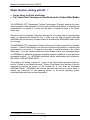
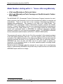
AEROMAG LAKOTA Wind Turbine Generator Manual Comprehensive Use, Care and Installation Manual for LAKOTA Wind Turbine Generator Copyright by AEROMAG Corporation, November 14, 2001, Version 4 United States and International Patents Pending Important: Please read and completely understand entire manual prior to any installation or assembly. 9234 East Valley Rd, Prescott Valley, AZ 86314 Phone toll free: 1-888-407-WIND (9463) Local Phone: 928–775–0085 Fax: 928-775–0803 E–Mail: [email protected] Web site: www.aeromaxenergy.com www.smallwindturbines.com 1 This page is intentionally left blank. 2 DISCLAIMER This document is provided for informational purposes only and AEROMAG makes no warranties, either expressed or implied, in this document. Information in this document is subject to change without notice. The entire risk for the use of, or results from, this document remains with the user. The example companies, organizations, products, people and events depicted herein are fictitious. No association with any real company, organization, product, person or event is intended or should be inferred. Complying with all applicable copyright laws is the responsibility of the user. Without limiting the rights under copyright, no part of this document may be reproduced, stored in or introduced into a retrieval system, or transmitted in any form or by any means (electronic, mechanical, photocopying, recording, or otherwise), or for any purpose, without the expressed written permission of AEROMAG Corporation. AEROMAG products may have patents, patent applications, trademarks, copyrights, and/ or other intellectual property rights covering subject matter in this document. Except as expressly written the furnishing of this document does not give you any license to these patents, trademarks, copyrights, or other intellectual property. Unpublished work Copyright 2001, AEROMAG Corporation. All rights reserved. AEROMAG, its logo, and slogan are either registered trademarks or trademarks of AEROMAG Corporation in the USA and/or other countries. The names of actual companies and products mentioned herein may be the trademarks of their respective owners. We appreciate your input, comments, questions and criticisms. Please contact us to improve and further evolve this user manual. 3 Want to live beyond the power lines? Set up your own self-reliant, fail-safe, hybrid energy system. United States and International Patents Pending AEROMAX INC. Next Generation Wind & Solar Energy Systems and Components 9234 East Valley Road, Prescott Valley, AZ 86314 Phone: 1-888-407-WIND (9463) FAX: 1-928-775-0803 www.aeromag.com or www.smallwindturbines.com E-mail : [email protected] 4 TABLE OF CONTENTS Disclaimer ___________________________________________________________ 2 Want to live beyond the power lines?_______________________________________ 4 Table of Contents ______________________________________________________ 5 Introduction __________________________________________________________ 7 Included with this wind turbine generator ____________________________________ 7 AEROMAG Warranty and Registration Policy for all AEROMAG wind turbine generators _________________________________________________ 8 Site Selection ________________________________________________________ 11 Site Selection Considerations ___________________________________________ 14 Topography _______________________________________________________ 14 Barriers___________________________________________________________ 15 Surface Roughness _________________________________________________ 15 Power loss with a 1000 W Generator on various surfaces ____ Error! Bookmark not defined. Two Rules of Thumb ________________________________________________ 16 Pre-installation Procedure for your LAKOTA wind turbine generator tower Structure _ 17 Important Notice: _____________________________________________________ 17 Tower selection for the following wind turbine generators utilizing 2” Water pipe towers __________________________________________________ 17 Tower selection for the following wind turbine generators utilizing 2” structural tubing _ 18 WHAT IS NOT INCLUDED WITH YOUR WIND TURBINE GENERATOR _________ 19 Tower Mast, Gin Pole, Mast Riser and Concrete ___________________________ 19 Tower Mast and Gin Pole ___________________________________________ 19 Mast Riser_______________________________________________________ 21 LAKOTA Wind Turbine Generator Tower Riser __________________________ 21 Note: ___________________________________________________________ 22 Concrete base pad and anchors ______________________________________ 22 THIS WIND TURBINE GENERATOR REQUIRES THE FOLLOWING TOOLS ______ 23 Maximum Allowable Ampacities of Insulated Conductors according to U.S. national electric code __________________________________________________ 24 Cable Selection for various Wind Turbine System Voltages___________________ 25 Line Losses for LAKOTA Wind Turbine Generator 12V, 24V, and 48V System Voltages at 1300 Watts of Peak Power_________________________________ 25 Line Losses for LAKOTA Wind Turbine Generator 12V, 24V, and 48V System Voltages at 500 Watts of Median Power ________________________________ 25 5 LAKOTA Wind Turbine Generator System Identification _______________________ 26 Identifying your specific Wind Turbine Generator___________________________ 27 Wind Turbine System check_____________________________________________ 30 Fitting your Generator Main Housing to your specific Tower Riser________________ 31 LAKOTA And LAKOTA S Wind Turbine Assembly____________________________ 32 Connecting your Wind Turbine Generator to your existing Tower Riser __________ 32 Connecting your Wind Turbine Generator Tail Fin and Boom Tube Assembly_____ 33 Connecting your Wind Turbine Generator Hub Assembly and Blade Array and Nose Cone_____________________________________________________________ 35 Installing the Nose Cone _____________________________________________ 39 NEW STYLE CONTROLLER 40 OLD STYLE CONTROLLER 41 Connecting your Control _______________________________________________ 42 Converting your Control into a Manual Load Divergence Center with optional DC input ___________________________________________________ 43 Final System Connection Considerations ___________________________________ 47 LAKOTA WIND TURBINE NORMAL OPERATION __________________________ 488 Safety Check _____________________________________________________ 488 Stopping the Wind Turbine Generator ________________________________ 488 Starting the Wind Turbine Generator _________________________________ 499 Turning OFF Your Renewable Energy System__________________________ 499 Lighting Protection and Grounding 50 Wiring Connections 51 LAKOTA WIND TURBINE TROUBLE SHOOTING 52 6 General Information about the LAKOTA INTRODUCTION Thank you, for choosing a wind turbine generator from the AEROMAG SMALL WIND TURBINE GENERATOR FAMILY. This wind turbine generator has been designed for greater safety and ease of installation utilizing superior components combined with the finest quality hardware available. Also available through AEROMAX is the optional AEROMAG LOAD TRANSPORT TILT TOWER KIT that utilizes forged and/or machined couplers/compression couplers with smoother and superior structural qualities. The machined threads are much easier for the layman to install when compared to conventional cut threads. This wind turbine generator combined with the comprehensive use, care and installation manual will instill in you the confidence to raise and lower your wind turbine generator with the AEROMAG LOAD TRANSPORT TILT TOWER KIT whenever necessary. The LAKOTA wind turbine generator was designed as a battery-charging unit for 12, 24 or 48-Volt Hybrid Energy Systems. Other System Voltages are available upon request. INCLUDED WITH THIS WIND TURBINE GENERATOR • Complete LAKOTA Wind Turbine Generator with PM Generator Technology • Stealth-Acoustic Uni-Directional Carbon Fiber Blades • One of the following Controllers: (According to your specification at the point of sale) • • Rectifier Module with Stop Switch (RM-240) (Default) • Manual Load Divergence Center with DC Breakers (MLDC240-200) • Automatic Load Divergence Center (ALDC240-120) • Full Wind Turbine Flight and Battery Charge Controller (180A CC) A Warranty Registration Cards for your warranty on the Wind Turbine Generator and for the warranty on your Stealth-Acoustic Carbon Fiber Blades with Hub Kit. The Warranty Registration Card must be returned within 60 days from the date of purchase in order to validate the AEROMAG Warranty. 7 General Information about the LAKOTA AEROMAG WARRANTY AND REGISTRATION POLICY FOR LAKOTA WIND TURBINE GENERATOR AND STEALTHACOUSTIC CARBON FIBER BLADES AEROMAG products are of the highest quality available in the renewable energy industry. AEROMAG offers several warranties for any manufacturing defects on your Wind Turbine Generator Unit as well as on your Stealth-Acoustic Carbon Fiber Blades depending on your specification at the point of purchase. All set-up procedures must be completed according to the enclosed use and care manual. AEROMAG’s warranty does not apply to damages caused by installation irregularities or misuse of the products. Carry In Service with Return Authorization. The end user is responsible for shipping and must pay any and all shipping charges in order to return the unit to AEROMAG and or an AEROMAG authorized agent for warranty service. If the necessary repairs are covered by the warranty, AEROMAG will pay the return shipping charges. If your unit requires service, it should be returned to AEROMAG Corporation USA. The warranty is not enforceable outside the USA without an approved registration authorization from AEROMAG. We may refer you to an authorized service center or we may authorize you to return the unit to the factory for service. Please do not return the unit to the factory without prior authorization. Whenever service is required you must present the original bill of sale as proof of the original date of purchase. This warranty gives you specific legal rights and these rights may vary from state to state. Except as specified below, this warranty cover all defects in material and workmanship of the wind turbine generator assembly. The warranty does not cover the following: 1. Damage resulting from negligence, accident, misuse, abuse, or neglect. 2. Damage resulting from failure to follow instructions supplied with the product. 3. Damage resulting from repairs by anyone not authorized by Aeromag Corporation. 4. Damage occurring during shipment of the product (claims must be submitted to the carrier). 5. Damage to any unit which has been altered or on which the serial number has been altered or removed. 6. Damage to or deterioration of the external housings due to excessive, severe, atmospheric degradation from extreme and unusual environments that require routine maintenance and refinishing service. 7. Damage caused by neglect and or failure to service when the required annual inspections is due as required by the unit’s USE AND CARE MANUAL. 8 General Information about the LAKOTA 8. Damaged if improperly connected to the equipment of other manufacturers. 9. Ordinary adjustments to the product as outlined by the USE AND CARE MANUAL. 10. Cost incurred by de-installation, re-installation and shipping of the product for service. 11. Products damaged by or due to improper or inadequate packaging when returned for Return Merchandise Authorization (RMA) purposes. This Warranty is void if the product is: 1. 2. 3. 4. Damaged through misuse, abuse or accident. Utilized in an unauthorized commercial or rental application. Modified or repaired by anyone not authorized by AEROMAG Corporation. Damaged because it is improperly connected to the equipment of other fabricators, installers or manufacturers. AEROMAG products need to be visually inspected every year. Inspect the Carbon Fiber Blades for abrasive damage from weather especially on the leading edge. If you live in a coastal or desert area, inspect your blades twice a year. It is important that you keep your Carbon Fiber Blades clean to maximize your power output. If you experience difficulties in inspecting your blades, contact AEROMAG at 1-888-407-9463 for assistance. If you experience a problem with your AEROMAG Wind Turbine Generator Unit, contact your nearest Authorized Distributor or AEROMAG direct (1-888-407-9463) to determine the nature of the problem. Either the Authorized Distributor or AEROMAG will issue a return authorization number to return the Wind Turbine Generator, or send you the necessary parts, or, at our option, repair the defective component. All returns accompanied with the purchase receipt will need to be shipped, freight, prepaid to AEROMAG. AEROMAG will pay the return shipping cost to you, the customer. All AEROMAG products must be registered for coverage by the warranty policy. Failure to return the warranty registration form within 60 days after your purchase will negate the warranty of your wind turbine and/ or operating system. 9 General Information about the LAKOTA Model Number starting with A1… 1 • Two Years on Parts and Labor • Three Years Parts Coverage on Stealth-Acoustic Carbon Fiber Blades AEROMAG warrants the wind turbine generator head assembly to be free from manufacturing defects in the materials and workmanship for a period of 2 years from the date of original purchase in the United States only. Should service be necessary under this warranty for any reason due to manufacturing defect or malfunctioning during the first 2 years from the date of original purchase AEROMAG will provide carry in repair service at an authorized AEROMAG repair center at no charge. The AEROMAG GTP (Guaranteed Turbine Performance Program) warrants the StealthAcoustic Carbon Fiber Blades to be free from manufacturing defects in materials and workmanship for a period of 3 years from the date of original purchase in the United States only. If you are located outside the United States consult your authorized dealer or AEROMAG for additional information regarding warranty conditions for your particular geographic location. For AEROMAG warrantee service authorization and information dial toll free 1 -888-407-WIND (9463). 1 For information on your model number, see page 26. 10 General Information about the LAKOTA Model Number starting with B1…2 • Seven Years on Parts and Labor • Ten Years Parts Coverage on Stealth-Acoustic Carbon Fiber Blades The AEROMAG GTP (Guaranteed Turbine Performance Program) warrants the wind turbine generator head assembly to be free from manufacturing defects in materials and workmanship for a period of 7 years from the date of original purchase in the United States only. Should service be necessary under this warranty for any reason due to manufacturing defect or malfunctioning during the first 7 years from the date of original purchase AEROMAG will provide carry in repair service at an authorized AEROMAG repair center at no charge. The AEROMAG GTP (Guaranteed Turbine Performance Program) warrants the StealthAcoustic Carbon Fiber Blades to be free from manufacturing defects in materials and workmanship for a period of 10 years from the date of original purchase in the United States only. If you are located outside the United States consult your authorized dealer or AEROMAG for additional information regarding warranty conditions for your particular geographic location. For AEROMAG warrantee service authorization and information dial toll free 1 -888-407-WIND (9463). This warranty will remain in effect for 7 years on the wind-turbine generator head unit and for 10 years on the Stealth-Acoustic Carbon Fiber Blades from the date of the first consumer’s purchase as shown on the original bill of sale from an authorized AEROMAG Dealer. AEROMAG will cover all parts and labor and at its option repair or replace any component of the operating system, or the entire operating system excluding blades which are covered separately. 2 For information on your model number, see page 26. 11 General Information about the LAKOTA Model Number starting with L1…3 have a Life Long Warranty • Life Long Warranty on Parts and Labor • Life Long Warranty on Parts Coverage on Stealth-Acoustic Carbon Fiber Blades The AEROMAG GTP (Guaranteed Turbine Performance Program) warrants the windturbine generator head assembly to be free from manufacturing defects in materials and workmanship. There is no time limit on the coverage of manufacturing defects in materials and workmanship. This warranty is only valid in the United States. The AEROMAG GTP (Guaranteed Turbine Performance Program) warrants the StealthAcoustic Carbon Fiber Blades to be free from manufacturing defects in materials and workmanship in the United States only. If you are located outside the United States consult your authorized dealer or AEROMAG for additional information regarding warrantee conditions for your particular geographic location. For AEROMAG warrantee service authorization and information call toll free 1 -888-407-WIND (9463) This warranty will remain in effect for the “life of the ownership” of the original purchaser of the wind -turbine generator head unit. It will also remain in effect for the life of the ownership of the original purchaser on the blade array (Blades) from the date of the first consumer purchase as shown on the original bill of sale from an authorized Dealer. AEROMAG will cover all parts and labor and at its option repair or replace any component of the operating system, or the entire operating system excluding blades which are covered separately. Should service be necessary under this warranty for any reason due to manufacturing defect or malfunctioning AEROMAG will provide carry in repair service at an authorized AEROMAG repair center at no charge. 3 For information on your model number, see page 26. 12 General Information about the LAKOTA Model Number starting with F1…4 have a Foreign Warranty • Two Years on Parts and Labor • Two Years Parts Coverage on Stealth-Acoustic Carbon Fiber Blades AEROMAG warrants the wind-turbine generator head assembly to be free from manufacturing defects in the materials and workmanship for a period of 2 years from the date-of-original-purchase. Should service be necessary under this warranty for any reason due to manufacturing defect or malfunctioning during the first 2 years from the date of original purchase AEROMAG will provide carry in repair service at an authorized AEROMAG repair center at no charge. The AEROMAG GTP (Guaranteed Turbine Performance Program) warrants the StealthAcoustic Carbon Fiber Blades to be free from manufacturing defects in materials and workmanship for a period of 2 years from the date of original purchase in the United States only. For AEROMAG warrantee service authorization and information dial toll free 1-888-407-WIND (9463). 4 For information on your model number, see page 26. 13 General Information about the LAKOTA SITE SELECTION Site selection is extremely important for optimal wind turbine generator (WTG) performance. The three primary requirements for optimum WTG performance are: (1) (2) (3) Relatively high average wind speed. Relatively low wind turbulence. Emotional intelligence and compliance among couples or partners. A higher than average wind speed will deliver a substantially higher annual energy output. If a site has high turbulence it will deliver less energy than a site with relatively the same wind speed but lower turbulence. A turbine located in a turbulent wind regime will also incur higher levels of stress and fatigue resulting in higher WTG maintenance than a low turbulence site. The most common problem with poorly sited turbines has been an emotional or aesthetic conflict between couples or partners. For example, Hazel wants the WTG tower located away from the bird feeders, while Bob wants the WTG installed on the windward side of his workshop (where the feeders are). Or Bill, who is being asked to sacrifice 70% of his wind turbine’s annual performance by installing it on the north side of his 2 story home where the prevailing winds (and the view) are out of the south. In this case, Bill is forced to choose between destroying all cost effective WTG performance and appeasing his partner’s concerns over scenic views to the south. The power available in the wind is proportionate to the speed of the wind cubed. Therefore a comparatively small increase in average wind speed can make a dramatic difference in power production. The theoretical energy available at a 9-MPH site (14.49 km/h) average speed is approximately 28% less then that at a site with a 10-MPH (16.09 km/h) average wind speed. SITE SELECTION CONSIDERATIONS When selecting a site for a wind turbine there are three factors that must be considered. In order of importance they are Topography, Barriers, and Surface Roughness. In addition, wind turbines located atop taller towers encounter less turbulence, harvest substantially more energy annually, and require less maintenance than units that have harvested the same energy values from turbulent flows. Topography During the evening, as the air cools, it tends to sink into low-lying areas and remain calm until warmed by the morning sun. Because of this effect, lower areas tend to have very little wind at night. In some sites the same effect can occur due to winter cooling as well. This phenomenon is usually responsible for lower levels of energy in the wintertime. This is why you must take into consideration that the relative annual energy distribution for your site could be considerably lower in the winter months. To help compensate for this factor you 14 General Information about the LAKOTA will want to place your WTG tower at the highest elevated land point on your site, provided that it is logistically practical to do so. There are also cases where the highest land point available is not the best WTG site. The highest point may be inaccessible or inconvenient due to vegetation or rough terrain. The high point may also be too far away for efficient power transmission or may expose the WTG to severe icing conditions. In addition, the highest point may not even always have the highest wind speed due to the micro dynamics of the site or the effects of terrain in the area around the site. There are a number of topographical effects that can provide the effect of concentrating or funneling wind coming from a particular direction. Some of the most important of these include a ridge or cliff perpendicular to the prevailing wind, a valley parallel to the prevailing wind with a topography that concentrates the wind, and/or a pass or saddle perpendicular to the wind. The only sure way to determine if a particular land feature acts as a wind concentrator is to simultaneously measure the wind at various points. You can get a good idea of relative wind speeds by informal experience, or by examining local vegetation for signs of wind damage. Use caution as areas of very high turbulence often accompany higher wind speed caused by increased wind concentration. A good way to observe the turbulence at a potential site is to fly a kite and watch the behavior of a series of 4 ribbons tied to the kite string on a moderately windy and sunny day. Watch the behavior of the ribbons. Are they all flying in the same direction with moderate flapping or are they flapping heavily and moving erratically? Barriers Barriers to the smooth flow of the wind (buildings, trees, etc.) generate wakes that may extend far downwind of the barrier. These wakes are areas of decreased wind speed and potentially damaging turbulence. Surface Roughness Wind flow is slowed by friction with the ground surface. The smoother the ground, the less the effect. The roug her the terrain, the greater the effect, and taller the tower will need to be to compensate. Assuming 30-MPH (48.3 km/h) winds and a 1000 Watt generator on a 20 ft (6.1m) tower, the following chart illustrates surface effect on power output. 15 General Information about the LAKOTA Power loss with a 1000 W Generator on various surfaces Surface Type Output Loss Smooth (sand or water) 900 watts 100 watts Medium (grass or crops) 800 watts 200 watts Rough 700 watts 300 watts (trees or houses) Two Rules of Thumb • A tower immediately downwind of a building should be at least twice the height of the building. • A tower should be at least 25 feet (7.62 m) higher than the highest barrier within a 500-foot (152.4 m) radius. Approximate Power Output vs. Tower Height 120 Approximate Monthly 103 kWh 100 80 kWh 80 Power Output [kWh] 60 kWh 60 40 20 0 100 ft 50 ft 40 ft Tower Height This figure illustrates an approximation of height versus energy production using an average wind speed, a 1000-Watt wind turbine generator, and a rough surface. Note that going from 40 up to 50 feet (25% higher tower) increases output by 33%, but going from 50 up to 100 feet (100% higher tower) yields only a further 25%. At a tower height of 40 feet (12.2 m), most surface turbulence effect is negligible except for that caused by houses and trees. 16 General Information about the LAKOTA PRE-INSTALLATION PROCEDURE FOR YOUR LAKOTA WIND TURBINE GENERATOR TOWER STRUCTURE All tower designs with guy wire cables depend entirely on these cables for support strength. Extreme care must be taken when handling the aircraft cable included with this kit. Any damage or kinking to cables must be avoided to insure that the structural integrity of the cable is not compromised. Before erecting your tower you should pre-fit the turbine and wires on and into the mast riser. You do not want to do this when the turbine is in the air. If the turbine does not fit, check the pipe dimension first. Variances in pipe dimension are common, and in some cases it may be necessary to file the pipe with a rough file in order to get a proper fit. IMPORTANT NOTICE: • • Never attempt to mount a turbine when the tower is in the air! Never install the turbine before the tower structure has been test lifted and all cables have been properly adjusted! Finished Tower Structure using the AEROMAG 2 inch Water Pipe Load Transfer Tower Kit. 17 Tower Selection for 2” Structural Tubing Load Transport Tilt Tower Kit TOWER SELECTION FOR THE FOLLOWING WIND TURBINE GENERATORS UTILIZING 2” WATER PIPE TOWERS Tower Specification Approximate Tower Height Application Southwest Windpower AIR 303 Module TOW 2-25 A 25 ft Southwest Windpower AIR 403 Module Southwest Windpower AIR 403 Marine Southwest Windpower AIR 403 Industrial TOW 2-25 W 25 ft Southwest Windpower Windseeker 502 Southwest Windpower Windseeker 503 TOW 3-28 W 5 28 ft WSW Wind Baron TOW 3-52 W5 52 ft AEROMAG Windseeker 503C TOW 3-76 W5 76 ft AEROMAG LAKOTA AEROMAG LAKOTA Marine Southwest Windpower AIR 303 Module TOW 2-47 A 47 ft Southwest Windpower AIR 403 Module Southwest Windpower AIR 403 Marine Southwest Windpower AIR 403 Industrial Southwest Windpower Windseeker 502 Southwest Windpower Windseeker 503 WSW Wind Baron TOW 2-47 W 47 ft AEROMAG Windseeker 503C AEROMAG LAKOTA AEROMAG LAKOTA Marine “W” type kits use 2-inch diameter pipe as a mast riser and the appropriate reducer. 45 Users with the TOW 3- 28 W, TOW 3- 52 W or TOW 3-76 W use the compression coupler reducer listed in the Use, Care and Installation Manual for AEROMAG Load Transport Tilt Towers. 17 Tower Selection for 2” Structural Tubing Load Transport Tilt Tower Kit TOWER SELECTION FOR THE FOLLOWING WIND TURBINE GENERATORS UTILIZING 2” STRUCTURAL TUBING Tower Specification Approximate Tower Height Application Southwest Windpower AIR 303 Module TOW 2-28 S 28 ft Southwest Windpower AIR 403 Module Southwest Windpower AIR 403 Marine Southwest Windpower AIR 403 Industrial AEROMAG LAKOTA S AEROMAG LAKOTA S Marine Southwest Windpower AIR 303 Module TOW 2-52 S 52 ft Southwest Windpower AIR 403 Module Southwest Windpower AIR 403 Marine Southwest Windpower AIR 403 Industrial AEROMAG LAKOTA S AEROMAG LAKOTA S Marine “S” type kits use 2-inch diameter structural tubing such as SS-20/ SS-40 or Tuff-20/ Tuff-40 pipe as a mast riser. 18 LAKOTA Wind Turbine Pre-Assembly Procedures WHAT IS NOT INCLUDED WITH YOUR WIND TURBINE GENERATOR Tower Kit, Tower Mast, Gin Pole, Mast Riser and Concrete Tower Kit The tower kit is not included with your wind turbine generator. We recommend that you select a tower from page 17. Only select a 25 or 28 ft tower if your wind turbine will be installed on a hilltop or a tower site that is extremely windy. Otherwise, select a 47 or 52 ft tower. This will minimize the wind turbine’s exposure to turbulence, thus maximizing your annual energy output of your generating wind system. Only select a tower kit with an –S extension if your LAKOTA wind turbine generator comes with a –S extension, i.e.: LAKOTA S or LAKOTA S MARINE. Tower Mast and Gin Pole The tower mast and gin pole are not included in this kit and must be obtained from your local water pipe supplier, hardware or plumbing store in addition to your AEROMAG LOAD TRANSPORT TILT TOWER KIT. For “W” type kits, you will need to purchase 2-inch diameter schedule 40 water pipe sections, 21 ft long. Some regions may have metric sizes or slightly different lengths. The quantity of pipe required is dependent on the particular kit that you have purchased (see chart on next page). The tower riser or mast riser will also need to be considered when purchasing your pipe. Different wind turbines call for different size risers that will vary between 3 ft and 6 ft in length. Be sure to review your wind turbine owner’s manual for this information. In addition to the pipe for the tower mast you will also need one 21-foot section of 2-inch diameter Schedule 40 water pipe for the gin pole. For “S” type kits, you will need to purchase 2-inch diameter structural tubing sections, 24 ft long. You may select SS-20, SS-40, or Tuff-20 for your structural tubing sections. The same tower riser considerations mentioned above still apply for your tower. Be sure to review your wind turbine owner’s manual for this information. 19 LAKOTA Wind Turbine Pre-Assembly Procedures Required Pipe Purchasing 6 Tower Kit Approximate Total Tower Height No. of 21 ft sections for Tower Mast 21 ft section for Gin Pole Total Number of 21 ft sections TOW 2-25 W 25 ft 1 1 2 TOW 2-47 W 47 ft 2 1 3 24 ft section for Gin Pole Total Number of 24 ft sections Required Pipe Purchasing 7 Tower Kit Approximate Total Tower Height No. of 24 ft sections for Tower Mast TOW 2-28 S 28 ft 1 1 2 TOW 2-52 S 52 ft 2 1 3 6 In addition, every tower requires a specific mast riser according to your wind turbine model. Refer to Mast Riser section, page 21 to determine the correct riser length. 7 In addition, every tower requires a specific mast riser according to your wind turbine model. Refer to Mast Riser section, page 21 to determine the correct riser length. If you selected a Tower Kit with a –S extension, make sure your wind turbine generator carries a –S extension as well. 20 LAKOTA Wind Turbine Pre-Assembly Procedures Mast Riser The mast riser is located at the top of the tower mast. The riser is used to provide standoff clearance between the wind turbine blades and the cables that support the tower. Water pipe sections come threaded on both ends, but the riser needs to be threaded on one end only. Towers utilizing compression coupler connectors use structural tubing and do not rely on threads for their connection. To make a riser, simply cut an end from a length of water pipe or structural tubing, or to save $$$, check with your pipe supplier for a remnant end. The turbine can never be mounted on an end that is threaded, unless the wind turbine utilizes a compression coupler only. A longer than required mast riser increases the risk of structural failure caused by increased stress concentration on the coupler joint at the bottom end of the riser section. Please refer to your wind turbine manufacturer’s manual for the correct mast riser length and specification. LAKOTA Wind Turbine Generator Tower Riser Required Pipe Purchasing for Tower Riser using Water Pipe Towers* Approximate Total Tower Height 2” Water Pipe Riser Length8 TOW 2-25 W 25 ft 4 ft TOW 2-47 W 47 ft 4 ft Tower Kit 8 Important: The LAKOTA Wind Turbine Generator has been designed to fit into a 2 inch (nominal) Schedule 40 wrought iron black pipe, not galvanized pipe. This pipe has a standard outside diameter of 2.375 inches and an inside diameter of 2.067 inches. Every LAKOTA Wind Turbine Generator has been machined and individually tested to properly fit into black iron pipe. Do not use galvanized pipe for the tower riser. 21 LAKOTA Wind Turbine Pre-Assembly Procedures Required Pipe For Tower Riser Structural Tubing Tower Approximate Total Tower Height 2” Structural Tubing, SS-20 Riser length 2” Structural Tubing, SS-40 Riser Length TOW 2-28 S 28 ft 4 ft 5 ft TOW 2-52 S 52 ft 4 ft 5 ft Tower Kit Note: If the mast riser is to be cut with a pipe cutter and not a saw you need to make sure that the inside of the pipe is properly reamed by the pipe supplier since a pipe cutter can leave a flange inside the pipe that is extremely difficult to file. Cutting into the pipe in smaller increments on the final turns will help reduce this flange. An experienced pipe threader/cutter should ream the inside end of the cut pipe with the reaming attachment that is built in to most threading/cutting machines. This is very important as the turbine may be configured to mount inside the pipe to a close tolerance. You may want to have your turbine head with you (do not install the blades onto the turbine head) for a test fitting when you have the riser cut. If the pipe has been cut with a saw it is usually easy to dress the inside diameter with a metal file. Concrete base pad and anchors In most permanent installations the tower anchors are made of ready-mix concrete, mixed and poured on site. Each anchor pad must weigh at least 800 lbs. or more for high wind sites and should whenever possible be recessed into the ground. An 800 pound anchor is equivalent to 4.5 cubic feet of volume (1.5 ft x 1.5 ft x 2 ft deep). Each anchor pad will use at least nine bags of ready-mix concrete (depending on size) while the base will use about seven bags of ready-mix concrete. Be sure to review the complete details in your tower kit manual or call AEROMAG at 1888-407-9463 for a detailed tower kit manual. 22 LAKOTA Wind Turbine Pre-Assembly Procedures THIS WIND TURBINE GENERATOR REQUIRES THE FOLLOWING TOOLS FOR ASSEMBLY After your tower structure has been successfully installed and you made sure with a test tilt that it is safe to install your wind turbine generator, you will need the following tools for assembling your wind turbine generator: Two or more of the following tools: Hub and Blade Array Assembly o o o o 24 mm or 15/16” box wrench 10 mm nut-driver, ratchet wrench, 10 mm socket 10 mm box wrench 4 mm hex key (included in the package) Tail and Tail Fin Assembly o 10 mm nut-driver, ratchet wrench, 10 mm socket o 10 mm box wrench o 17 mm box wrench Tower Riser and Yaw Shaft Assembly for Water Pipe Tower Structures o 17 mm box wrench Tower Riser and Yaw Shaft Assembly for Structural Tubing Tower Structures (Compression Coupler Assembly for LAKOTA S and LAKOTA S MARINE only!) o 10 mm nut-driver, ¼ inch drive ratchet with a 10 mm socket o 10 mm Box Wrench Additional Tools Required o Pipe thread compound for compression coupler bolts (available at your local hardware store) o Tape measure, 12 ft or longer and Multi-meter (Ohm-meter) o One semi-round metal file o One medium slotted screwdriver o One medium Phillips head screwdriver o One rubber mallet or hammer and wood block o ½ inch heavy duty electrical tape o Quality leather work gloves o Safety glasses or goggles especially in windy places o Hard hats or safety helmets are strongly recommended for tower erection 23 LAKOTA Wind Turbine Pre-Assembly Procedures MAXIMUM AMP CAPACITY OF INSULATED CONDUCTORS/ SYSTEM WIRES ACCORING TO U.S. NATIONAL ELECTRIC CODE Size Temperature Rating of Conductor/System Wires 60°C (142oF) AWG or 75°C (167oF) 90°C (194oF) Types: Types: Types: TW, UF FEPW, RH, RHW, THHW, THW, THWN, XHHW, USE, ZW TBS, SA, SIS, FEP, FEPB, MI, RHH, RHW-2, THHN, THHW, THW-2, THWN-2, USE-2, XHH, XHHW, XHHW-2, ZW-2 kcmil Copper Conductors/System Wires (Amps) 18 16 14 12 10 8 20 25 30 40 20 25 35 50 14 18 25 30 40 55 6 4 3 2 1 55 70 85 95 110 65 85 100 115 130 75 95 110 130 150 1/0 2/0 3/0 4/0 125 145 165 195 150 175 200 230 170 195 225 260 24 LAKOTA Wind Turbine Pre-Assembly Procedures Cable Selection For Various Wind Turbine System Voltages Line Loss For LAKOTA Wind Turbine Generator 12V, 24V, And 48V System Voltages At 1300 Watts Of Power 12 Volts 24 Volts 48 Volts Multi-strand Wire Distance Distance Distance Distance Distance Distance RecomResistance up to, up to, up to, up to, up to, up to, mended per 1000 ft size 2% loss 4% loss 2% loss 4% loss 2% loss 4% loss 0.264 Ω at 2.5 m 5.1 m 10.2 m 20.4 m 40.9 m 81.8 m #4 (420/30) 25 mm2 4.0 m 8.0 m 16.1 m 32.3 m 64.6 m 129.3 m #2 (665/30) 0.167 Ω at 35 mm2 5.0 m 10.1 m 20.3 m 40.6 m 81.2 m 162.4 m #1 (836/30) 0.133 Ω at 50 mm2 6.4 m 12.8 m 25.7 m 51.4 m 102.9 m 205.7 m #1/0 (1064/30) 0.105 Ω at 55 mm2 8.04 m 16.08 m 32.1 m 64.3 m 128.6 m 257.2 m #2/0 (3325/34) 0.084 Ω at 70 mm2 Line Loss For LAKOTA Wind Turbine Generator 12V, 24V, And 48V System Voltages At 500 Watts Of Median Power 12 Volts 24 Volts 48 Volts Multi-strand Wire Distance Distance Distance Distance Distance Distance RecomResistance up to, up to, up to, up to, up to, up to, mended per 1000 ft 2% loss 4% loss 2% loss 4% loss 2% loss 4% loss size 6.6 m 13.3 m 26.6 m 53.2 m 106.4 m 212.8 m #4 (420/30) 0.264 Ω at 25 mm2 10.5 m 21.0 m 42.0 m 84.1 m 168.2 m 336.4 m #2 (665/30) 0.167 Ω at 35 mm2 13.2 m 26.4 m 52.8 m 105.6 m 211.2 m 422.4 m #1 (836/30) 0.133 Ω at 50 mm2 16.7 m 33.4 m 66.8 m 133.7 m 267.5 m 535.0 m 20.9 m 41.8 m 83.6 m 167.2 m 334.4 m 668.8 m #1/0 (1064/30) #2/0 (3325/34) 0.105 Ω at 55 mm2 0.084 Ω at 70 mm2 25 LAKOTA Wind Turbine Pre-Assembly Procedures LAKOTA WIND TURBINE GENERATOR SYSTEM IDENTIFICATION Locate the cover plate on the main body housing. The cover plate contains all the information needed to identify your specific wind turbine generator. Use the table on the following page to help you to identify your specific wind turbine generator. Model Number (X1-###-…)9 Serial Number (3-###-….) Cover Plate The first number on the cover plate is the model number. It determines your specific wind turbine generator. The second number is the serial number. Both numbers will be needed in case of a defect or malfunction of the wind turbine generator in order to issue a return authorization number. It is important that you keep a record of your Model Number and Serial Number. Take the time and record it in the table below. Model Number (Starting with X1-007-….) 9 Serial Number (Starting with 3-007-….) 9 X represents an alphabetical character describing your specific warranty, i.e. A1, B1, C1, or L1. Your specific warranty is listed beginning on page 7. 26 LAKOTA Wind Turbine Pre-Assembly Procedures Identifying Your Specific Wind Turbine Generator Use the table below to determine your specific wind turbine generator. Your model number is generated from the voltage, edition, rotor and tail specification you specified before or at the point of purchase. Model number Voltage Nominal 12 V -0000 24 V • • -0010 • -0020 -0030 • • • -0013 • -0023 • • -0053 -0006 • • -0016 • -0026 -0036 -0046 -0056 • • • Marine Extended • • • • • • • • • • • • • -0043 Rotor • • • • -0050 -0033 Land • -0040 -0003 48 V Edition Tail Regular • • • • • • • • • • • • 27 Short • • • • • • • • • • • • • • • Long • • • • • • • • • • • • LAKOTA Wind Turbine Pre-Assembly Procedures INVENTORY AND PACKAGING COMPONENTS Part 1: LAKOTA Wind Turbine Generator Body Assembly Approximately 30 pounds (14 kg) Use, Care and Installation Manual Wind Turbine Head Assembly 2 1 Stainless Steel Metric Hex Head Cap Screw M10 x 25 Stainless Steel Yaw Shaft Clamp OR 1 2 1 6 6 Part 2: Stainless Steel Compression Coupler End Cap Brass Compression Coupler Rings Stainless Steel Compression Coupler Distance Ring Stainless Steel Metric Hex Head Cap Screw M6 x 60 Stainless Steel Metric Medium Split Lock Washer for M6 LAKOTA Tail Fin Assembly Approximately 3 pounds (1.4 kg) Part 3: 1 1 2 1 Left Tail Fin Right Tail Fin Support Braces Cross Brace 10 5 2 3 Stainless Steel Metric Flat Washer for M6 Stainless Steel Metric Nylon Insert Locknut for M6 Stainless Steel Metric Hex Bolt M6 x 16 Stainless Steel Metric Hex Bolt M6 x 45 LAKOTA Blade Array and Tail Boom Assembly Approximately 8 pounds (3.6 kg) 3 1 Uni-Directional Carbon Fiber Blades Stainless Steel Tail Boom 28 LAKOTA Wind Turbine Pre-Assembly Procedures Part 4: LAKOTA Hub Assembly Approximately 3 pounds (1.4 kg) 1 2 1 2 1 Stainless Steel or Carbon Fiber Hub Plate Neoprene Damper Stainless Steel or Carbon Fiber Hub Cover Replacement Torque Key (One Extra) Stainless Steel Torque Ring 1 1 Stainless Steel Metric Nylon Insert Locknut for M16 Stainless Steel Metric Flat Washer for M16 3 Stainless Steel Metric Flat Head Socket Cap Screw M6 x 12 Metric Short Arm Hex Key 4mm for Flat Head Socket Cap Screw M6 x 12 1 Part 5: 12 24 12 Stainless Steel Metric Hex Head Cap Screw, M6 x 55 Stainless Steel Metric Flat Washer for M6 Stainless Steel Metric Nylon Insert Locknut for M6 1 Spinner One of the following Modules ° ° ° Rectifier Module with Stop Switch (Default) Manual Load Divergence Center Automatic Load Divergence Center ° Full Wind Turbine Flight and Battery Charge Controller (The Full Wind Turbine Flight and Battery Charge Controller may be shipped separately). In the unlikely case that one or multiple items were omitted or lost during shipping and handling contact your closest AEROMAX Dealer or AEROMAG directly at 1-888-4079463. Make sure to have your model and serial number ready to make identification of your specific wind turbine generator easier for our technical support team. The model and serial number are located on the side face of the main body housing above the yaw shaft or compression coupler assembly. Refer to page 26 for further details on your serial and model number. 29 LAKOTA Wind Turbine Pre-Assembly Procedures WIND TURBINE SYSTEM CHECK Tools required: 1 Multi-meter (Ohmmeter) The following tests have been made at our factory. However, in case internal shipping damage could have occurred to the wind turbine or one of its electrical components, we recommend that you perform the following two operational tests. Test One: Test Two: 1. Set your Multi-Meter to read AC Voltage in the range of 1-5 Volts. 2. Connect the Multi-Meter to the first pair (any pair, wire one – wire two) of wires and slowly turn the shaft of the generator assembly by hand. 3. Your Multi-Meter should read a voltage reading that confirms proper wiring. 4. Repeat step two and three for the following wire pairs: Wire one – Wire three Wire two – Wire three 1. Set your Multi-Meter to read Resistance (Ω, Ohm) 2. Place one of the Multi-Meter probes to one of the first lead wire from the yaw shaft or compression coupler assembly and the other Multi-Meter probe to the aluminum housing. 3. The Multi-Meter should read a very high resistance (Mega Ohm) or “OL” for over limit. 4. Repeat step two and three for wire number two and wire number three. 5. If you are using a Multi-Meter that omits a “beep” when both probes are connected to each other, you may follow step two and three using your “beep” feature. Your Multi-Meter should not omit a “beep” while repeating step two and three. If your Multi-Meter does not indicate an open circuit in test two or emits a “beep” in test two, please contact AEROMAX direct at 1-888-407-9463 or your authorized AEROMAX Dealer/Distributor. 30 LAKOTA Wind Turbine Pre-Assembly Procedures FITTING YOUR GENERATOR MAIN HOUSING TO YOUR SPECIFIC TOWER RISER Tools required: 1 semi-round, rough file For proper fitting procedure perform the following instructions of this section on a bench or table. Fitting a tower riser onto the yaw shaft on a bench or table reduces the possibility of an accident occurring. Note 1: This section is not applicable if you have purchased a LAKOTA S or LAKOTA S MARINE Wind Turbine Generator with a Compression Coupler Assembly at the Yaw Shaft. If you have purchased a LAKOTA S or LAKOTA S MARINE to fit to a 2 inch Structural Tubing Tower Riser utilizing a compression coupler, please see note 2 on this page. The inside diameter of the tower riser pipe may need to be filed and cleaned for a proper fit with the yaw shaft assembly. Do not file the three fins on the yaw shaft to enable a proper fit with the tower riser. Filing the yaw shaft fins may cause the yaw shaft to separate from the tower riser under certain conditions. If the yaw shaft of the LAKOTA Wind Turbine Generator does not fit properly into the tower riser after removing excessive burrs and sharp edges, turn the yaw shaft approximately 30 degrees and repeat the above procedures. To reduce vibration induced by the wind turbine generator, make sure that the tower riser end is milled flat and not cut with a rough saw blade. The milled surface enhances the structural bond between the yaw shaft and yaw shaft clamp and significantly reduces noise emission in the form of low-pitch vibrations through the tower structure. Note 2: This section is only applicable if you have purchased a LAKOTA S or LAKOTA S MARINE wind turbine generator with a Compression Coupler Assembly on the yaw shaft. To reduce vibration induced by the wind turbine generator, make sure that the tower riser end is milled flat and not cut with a rough saw blade. The milled surface enhances the structural bond between the compression coupler assembly and tower riser and significantly reduces noise emission in the form of low-pitch vibrations through the tower structure. The compression coupler rings must be mounted using a malleable hammer and/ or wood block on the structural tubing. 31 LAKOTA and LAKOTA S Wind Turbine and Control Assembly Procedures LAKOTA AND LAKOTA S WIND TURBINE ASSEMBLY Connecting Your Wind Turbine Generator To Your Existing Tower Riser Tools required: 17-mm box or socket wrench Your wind turbine generator tower should now be properly installed and test lifted to assure a safe and working tower structure. Be sure that the wires from the yaw or compression coupler assembly form three separate uninterrupted cable runs. Refer to the wire size table (page 25) to verify wire size. Wire size needs to be selected according to your acceptable power loss/distance from the turbine to the Control/Battery Bank. The WTG is shipped without wire terminals on the wires. We recommend that you use standard wire terminals designed for #8 AWG wire and use wire connectors that match the wire size required for wire runs to the control center. Use heat shrink tubing or heavy-duty electrical tape to reinforce the connection between each cable pairs. When the wind turbine generator wires have been connected to the existing tower wires, slide the wind turbine generator assembly onto the tower riser until the yaw shaft is snug and fully inserted onto the riser pipe. Tighten the two-yaw shaft clamp bolts (M10 x 25) and then torque to 43-ft lb. (58 N⋅m). Repeat Electrical Test One (page 30) at the control center next to the battery bank or PowerCell 10. Twist together the three AC wires from the tower structure using a wire nut at the bottom of the tower or next to the control center. Do not connect the three AC wires to the control center. NEVER connect the AC wires to the battery bank. 10 PowerCell is a trademark of AEROMAG Corporation and represents a specific energy storage unit. Call AEROMAX Corporation at 1-888-407-9463 and request more information about your PowerCell unit. 32 LAKOTA and LAKOTA S Wind Turbine and Control Assembly Procedures Connecting Your Wind Turbine Generator Tail Fin And Boom Tube Assembly Tools required: 10-mm box wrench 10-mm nut driver or drive ratchet and 10 mm socket 17-mm box wrench Caution: secure the tail boom onto the back of the generator housing before attaching tail fins. The tail assembly is now ready to be secured onto the wind turbine generator. The following steps are necessary in order to properly secure tail assembly onto the WTG: 1. Lubricate the round end of the boom tube with light oil. 2. Prior to inserting the boom tube into the generator housing line up the boom tube mounting holes with those in the generator housing. This will simplify bolt installation, as the boom tube is difficult to rotate when fully seated. 3. Insert the lubricated end of the boom tube into the end of the generator unit. Once the boom tube is inserted it should fit snugly. 4. When the holes are lined up insert an M10 x 70 bolt using a M10 flat washer on each side of the boom tube. Use a 17-mm box wrench or socket to install an M10 x 70 locknut. Torque to 55-ft lb. (75 Nm). 33 LAKOTA and LAKOTA S Wind Turbine and Control Assembly Procedures The tail fin is secured onto the boom tube as follows: 1. Install each tail fin by placing a rectangular spacer between the tail fin and boom tube. 2. Insert three M6 x 50 bolts through the holes of the tail fins and boom tube using an M6 flat washer on each side of the tail fins. Loosely attach M6 locknuts. 3. Using two M6 x 50 bolts position tail brace between the bottom portion of the tail fins using a M6 flat washer on each side of fin (4 required). Loosely attach M6 locknuts. 4. Gradually tighten M6 lock nuts until fin assembly is secure to tail boom then torque to 8-ft lb. using a 10mm box wrench and nut-driver or socket wrench. 34 LAKOTA and LAKOTA S Wind Turbine and Control Assembly Procedures 5. Tighten the tail fin brace bolts to 8-ft lb. of torque using a 10-mm box wrench and 10 mm nut driver or socket wrench. 6. The tail assembly is now complete. Connecting Your Wind Turbine Generator Hub Assembly, Blade Array And Nose Cone Tools required: 24-mm box wrench 10-mm nut driver or drive ratchet with 10-mm socket 10-mm box wrench 4-mm hex key (included in package) Place all components listed on the packing list on a clean, flat surface. Install the torque key and then the hub torque ring onto the LAKOTA generator shaft. Place the hub plate onto the LAKOTA generator shaft, carefully aligning the three inner holes on the hub plate with the three holes on the hub torque ring. 35 LAKOTA and LAKOTA S Wind Turbine and Control Assembly Procedures Locate the three flat-head M6 x 12 setscrews and apply one drop of thread locking compound to the middle of the threads of each set screw. Insert the three setscrews through the hub plate clearance holes and screw into the hub torque ring as shown. Using the 4-mm socket wrench tighten setscrews evenly until each is securely fastened to the hub plate. After completing this assembly remove the assembled hub plate and torque ring. Insert nine M6 x 55 hex head bolts through the nine holes in the hub plate from the rear where the hub torque ring is located. The hex head of the bolts should be on the same side as the hub torque ring using an M6 washer on each hex head cap screw. Next, place one of the hub dampers over the nine bolts on the hub plate/torque ring assembly. Place the hub portion of the three wind turbine blades over the bolts on the plate/torque ring assembly. Place a second hub damper and the hub cover plate over the wind turbine blade array. Install a M6 flat washer over six bolts followed by the hex locknuts. 36 LAKOTA and LAKOTA S Wind Turbine and Control Assembly Procedures Do not install a washer or locknut on the bolts at the apexes of the triangular hub plate at this time. Tighten the six locknuts using a 10-mm box wrench and a 10-mm socket wrench or nut driver. Do not completely tighten locknuts but make sure the turbine blades are firmly secured. The box wrench is used on the rear hex head bolts and the socket wrench or nut driver is used for the locknuts on the hub cover plate. Make sure that the curved side (lifting side) of each blade faces the LAKOTA wind turbine generator unit. NOTE: The radius of the tip should now face the right side while the trailing edge (thin edge) should face to the left side for a blade in a vertical upright position. The blade rotation is clockwise when facing the generator unit. Tools Required: Measuring Tape With the measuring tape verify the length between blade tips to make sure that all blades have been assembled exactly 120 degrees apart. If needed adjust the blades accordingly. After all adjustments have been made, torque each of the six locknuts to 9 ft lbs. Make sure that all bolts have been tightened evenly. Fasten the completed blade array assembly onto the wind turbine generator shaft using the M16 x 2 locknut and washer supplied. 37 LAKOTA and LAKOTA S Wind Turbine and Control Assembly Procedures Tighten the M16 x 2 locknut using a ratchet with a 24-mm socket (15/16 in.) while holding the blade array in place. We recommend a torque setting of 14-ft lb. for the drive shaft locknut. The blade array will be properly assembled when the locknut bottoms against the hub plate and two to four complete threads protrude past the M16 x 2 locknut. OR Tighten the 24-mm (15/16-in.) locknut with a socket wrench by holding the LAKOTA wind turbine generator shaft with a 10-mm box wrench and blade assembly. We recommend a torque setting of 14-ft lb. for the generator shaft locknut. 38 LAKOTA and LAKOTA S Wind Turbine and Control Assembly Procedures Installing the Nose Cone Slip the nose cone onto the three remaining bolts. There should be only one unused bolt on each blade mounting block section. Place an M6 washer onto each bolt then install a hex head locknut. Install the locknuts using a 10 mm box wrench and a 10 mm socket wrench and torque to 9 ft lb. Make sure that all bolts have been tightened evenly. Finished Hub Array Assembly. 39 LAKOTA and LAKOTA S Wind Turbine and Control Assembly Procedures NEW STYLE CONTROLLER 40 LAKOTA and LAKOTA S Wind Turbine and Control Assembly Procedures OLD STYLE CONTROLLER 41 LAKOTA and LAKOTA S Wind Turbine and Control Assembly Procedures CONNECTING YOUR CONTROLLER Your wind turbine generator comes with a simple control. The control allows you to connect your LAKOTA wind turbine generator with alternating current output rectified to charge the battery bank that stores energy in the form of direct current. The rectifier module also prevents the battery bank from back feeding into the wind turbine generator. If you are using the control you must ensure through your existing renewable energy system that the batteries cannot be overcharged. A proper Automatic Load Divergence (i.e. Inverter with optional wall heater, warm water heater) must be installed before you proceed to connect the controller to the wind turbine generator and battery bank. If you do not have a load divergence unit installed in your existing renewable energy system you may convert your rectifier controller to a controller with manual load divergence breakers. A Manual Load Divergence Breaker option will require that you monitor your battery bank voltage closely. A Manual Load Divergence Breaker will not protect your battery bank from an over-voltage condition. The Manual Load Divergence Center could also be utilized to accommodate additional DC Load Inputs into the existing battery bank. Old Style Controller Old Style Controller 3 Phase AC Input terminals: The order of how the three AC input cables are attached to the input terminals is not relevant. Controller as supplied with your wind turbine generator 42 Controller upgraded to a manual load divergence center with additional solar input. (Additional parts such as DC breakers or conduit adapter are not included). LAKOTA and LAKOTA S Wind Turbine and Control Assembly Procedures Converting Your Controller Into A Manual Load Divergence Center With Optional DC Input Old Style Controller Additional DC Input using 1 ½” NPT conduit 3 Phase AC Input terminals From Wind Turbine Generator Red = Positive Black = Negative Stop Switch ON = Break ON OFF = Break OFF Load Divergence or Dump Load using ¾” NPT conduit Additional Input using 1 ½” NPT conduit Red = Positive Black = Negative DC Output terminals to battery bank Additional Input using 1 ½” NPT conduit Red = Positive Black = Negative This Controller has been modified to utilize one Manual Load Divergence and one DC (solar) input. The controller will adapt to a maximum of two 100 AMP DC breakers in this enclosure. Several combinations are therefore possible and have to be explored 43 LAKOTA and LAKOTA S Wind Turbine and Control Assembly Procedures and evaluated by the installer of the wind turbine generator to be compatible with the existing renewable energy system. Combinations could include but not be limited to two of the following: Option 1: Up to two of the following 1 Wind Turbine Circuit Breaker (up to 100 Amp) 1 DC (Solar) input Circuit Breaker (up to 100 Amp) 1 Load Divergence Breaker (up to 100 Amp) Option 2: 2 Load Divergence Breaker (up to 100 Amp each) First, assemble the one or two breakers according to your selection from the above options using the supplied four hex head cap screw supplied with the enclosure. Decide on how you want to use your Manual Load Divergence Center. If you are connecting a Load Divergence Breaker, connect a positive (red) #2 AWG multi-stranded wire from the positive (red) battery (DC) output terminal to upper lug of the breaker. Your cable must come from the positive (red) 3/8” terminal and follow at the folded right hand edge of the enclosure, below the stop switch and turn into the left breaker position. This allows enough bend radii on the cable. Exit on the lower lug of the same breaker with another #2 AWG multi-stranded wire and exit on the lower of the two ¾” NPT knock-outs or the 1 ½” NPT knockout to your Divergence Load, wall heater or warm water heater. Utilize either flex or stiff conduit to adapt to the pre-manufactured knockouts. In a similar fashion for the negative (black) terminal, start from the negative output terminal (black) and exit through the upper of the two ¾” NPT knockouts or the 1 ½” NPT knockout to the negative terminal of your divergence load. Utilize #2 AWG multi-stranded wires as well for this connection. Refer to page 24 to select a lower or different wire gauge for DC breakers of value other than 100 Amp. 44 LAKOTA and LAKOTA S Wind Turbine and Control Assembly Procedures If you are connecting an additional DC (solar) input breaker, connect a positive (red) #2 AWG multi-stranded wire from the positive (red) source (solar panels) to the upper lug of the right hand breaker. Exit on the lower lug of the same breaker with another #2 AWG multi-stranded wire and connect it to the DC Output positive (red) terminal. Perform a similar operation for the negative (black) DC connection. Connect a negative (black) #2 AWG multi-stranded wire from the negative (black) source (solar panels) to the negative (black) DC Output terminal of the controller. DC Output terminals to battery bank Red = Positive Black = Negative DC Output terminals to battery bank with load divergence and solar input breaker close-up. Red = Positive Black = Negative Note: If your existing renewable energy system uses an inverter with netmetering capabilities, installing a load divergence will be optional. To connect your Controller to the Battery Bank, connect the positive (red) DC Output terminal to the positive (red) terminal of the battery bank and the negative (black) DC Output terminal to the negative (black) terminal of the battery bank. You cannot connect your Controller directly to an inverter! Do not connect your AC wires from your wind turbine generator directly to the battery bank. 45 LAKOTA and LAKOTA S Wind Turbine and Control Assembly Procedures OTHER OPTIONAL CONTROL CONFIGURATIONS 46 LAKOTA and LAKOTA S Wind Turbine and Control Assembly Procedures FINAL SYSTEM CONNECTION CONSIDERATIONS Proper wiring of the batteries, installation of wind turbine generator to the tower, raising of the tower, and securing of the tower have to be completed prior to beginning this section. If any of the aforementioned steps have not been properly completed, then STOP and go back and finish those steps first so unfortunate events can be avoided. WARNING: • • • Batteries are capable of storing a tremendous amount of energy. Under certain conditions the stored energy may be discharged in a very short time in the form of an explosion. Lead-acid batteries give off hydrogen gas, especially during the charging cycle and to a lesser extent during discharging. Hydrogen gas is extremely explosive. Venting is most important. The following steps must be followed to prevent serious personal injury: 1. Never connect the regulator to the batteries, which are gassing (bubbling). Make sure the battery area is properly ventilated. 2. Disconnect (at the fuse box) all charging sources and all loads (solar panel, lights, appliances, etc.) and wait for 1 hour (to let the hydrogen gas clear the area) before making any battery connections. 3. Wrap non-working portions of metal tools with vinyl electrical tape to prevent sparks in case the tool is dropped across the battery terminals. 4. Wear eye protection and rubber gloves, and keep plenty of water and baking soda near the battery work area. (Sprinkle baking soda on battery acid spills. Acid is neutralized when foaming stops.) 5. Follow all connection sequences specified in this manual. A spark will be produced at the final connection point. This spark can ignite hydrogen gas if the area is not properly ventilated. NOTE: Use the proper size terminal lugs when connecting to the batteries. 47 LAKOTA and LAKOTA S Wind Turbine Usage Procedures LAKOTA WIND TURBINE NORMAL OPERATION Safety Check At this point, the installation of your renewable energy system should be completed. Follow the instructions from the manufacturer to turn on the inverter. To start wind turbine generator and solar array charging of the batteries, place the “WIND ON” or “BREAK OFF” and the “SOLAR ON” breaker to the up or “ON” positions. There are a few basic operational procedures to learn and be followed. WARNING: Always observe and follow these safety precautions. Failure to adhere to the following precautions could lead to serious injury and even death. 1. A licensed and qualified electrician should do the maintenance of high voltage systems (64 Volts and greater). 2. Avoid contact with the rotor blades (propellers) during high speed operation. Contact with moving rotor blades (propellers) can be lethal. Make sure that children and others cannot climb the tower mast. Keep ladders, steps, or any object that could give access to climbing the mast away from the tower structure. 3. When lowering or raising a tilt tower, follow all safety instructions from the manufacturer and installer. Make sure the area where the tower or its guy wires could fall is clear of people. 4. Batteries may emit explosive and irritating gases while charging. Never turn on a light switch, make any electrical connection, light a match, or make any type of spark near a battery that has recently been charged. 5. Use protective gloves and eyeglasses when working around a battery. 6. NEVER place any object on top or near the controller enclosure or the Diversion Load Resistor (load dump system). These devices must dissipate heat as part of normal operation. FIRE AND FAILURE can result if any airflow is blocked. NOTE: Make sure that you read and understand all the information that comes with the controller system for your renewable energy system. Failure to follow those instructions can cause damage to your renewable energy system, and more importantly can cause injuries or even death. If you have any questions or concerns while installing either your wind turbine generator or control system contact your AEROMAX Distributor or AEROMAX Direct. 48 LAKOTA and LAKOTA S Wind Turbine Usage Procedures Stopping the Wind Turbine Generator To stop the wind turbine generator and propeller from turning in the wind, move the wind switch to the “ON” (breaker ON) position on the controller. The propeller should quickly come to a stop, i.e. it will cease to function as an airfoil and will turn very slowly in a moderate wind. The propeller may also come to a complete stop in winds that are strong enough to tilt the wind into the governing position. However, the braking system will not stop the wind turbine generator in strong winds just below the tilt-up governing speed or in very high winds. If, after 30 seconds of braking attempts, the propeller cannot be stopped, wait for the wind to die down. Leaving the switch in the “ON” (breaker ON) or down position in high winds with the propeller turning at high speed can destroy the wind turbine generator unit, which will void your warranty. With the wind turbine generator and propeller stopped and the wind switch of the controller in the “ON” (brake ON) or down position, the propeller will turn very slowly, well below airfoil operational speeds, even in hurricane force winds. This is the safe and correct way of placing the generator in a non-operational status for storms when the cabin is not being used, when the battery is fully charged in systems without an automatic regulator, etc. or for periods of a year or more. Starting the Wind Turbine Generator To start the wind turbine generator, place the wind switch in the “OFF” (breaker OFF) position. The propeller will start to rotate depending on wind conditions, usually at 3-5 mph. If there is sufficient wind, 6-8mph, the propeller will quickly gain speed to the point where the generator will start delivering a significant amount of power to the load. Once started the propeller will continue to run down to the winds below its starting point, without delivering any significant amount of power. Turning OFF Your Renewable Energy System If your renewable energy system will not be used for up to three months, make sure the battery is full. Switch OFF ALL input sources (wind, solar, etc.), turn OFF all DC loads by turning OFF the load switch of the controller, and turn OFF the inverter. If your renewable energy system will not be used for three months to a year, follow the above steps. Clean and dry the battery tops, and disconnect the battery by removing the fuse(s) or by opening a battery connection. The battery should be recharged once a year if the system is dormant. 49 LAKOTA and LAKOTA S Wind Turbine Usage Procedures Lightning Protection And Grounding If you are in an area where lightning strikes are a problem, you should be concerned about erecting a high tower near your home. While local conditions vary too much to give you definitive advice about lightning protection for your tower, the following are some general guidelines. The basic principle of lightning protection is to provide an easy path into the ground to minimize damage. If the ground in your area is fairly moist or otherwise electrically conductive, once a lightning strike reaches the ground, it will quickly dissipate into the conductive soil. In very dry frozen or gravely soil, or on bare rock, special effort must be made to minimize the electrical resistance of the connection into the ground. Where possible, connection to the ground may be by driving an approximately 8 foot long copper or metal rod or pipe into the ground. If there is no soil at all, (i.e. bare rock) a ring of conducting material should be placed around the area to protect the tower structure, wind turbine generator as well as surrounding structures. In this situation, a metal fence with a good continuous electrical connection is a possibility. You should not ground the tower structure to the casing of a well with an electrical pump installed and in use. Essentially, you want to connect everything in your system to the ground. If you have a metal tower its base should be solidly connected to a ground. If you have a wooden tower structure, you should run a #8 AWG wire from the wind turbine riser at the top of your tower to your grounding rod. In addition, ground all guy wires. Connect all ground connections to each other. If any are near buildings that have lightning protection systems, connect your tower grounding system to the lightning protection system of the building. Avoid sharp bends in wiring that is part of your lightning protection system. A sharp bend presents large electrical impedance to a lightning strike and may cause the lightning to arc out of the wire. You can use this to your advantage by deliberately introducing sharp bends into the wiring that goes from your tower to your control unit. This advice makes it less likely that lightning will enter your house. 50 LAKOTA and LAKOTA S Wind Turbine Usage Procedures CAUTION THE GREEN WIRE IS NOT A GROUND DO NOT CONNECT ANY WIRES FROM THE WINDINGS TO GROUND Step 1: Connect the two blue wires together using o ne wire nut. Step 2: Connect the two orange wires together using one wire nut. Step 3: Connect the two gray wires together using one wire nut. Step 4: Connect the red wire to the first wire of the cables coming from the cable hose. Step 5: Connect the black wire to the second wire of the cables coming from the cable hose. Step 6: Connect the white wire to the third wire of the cables coming from the cable hose. Step 7: Cap the green neutral wire with a wire nut. DO NOT CONNECT TO GROUND It might be necessary to open the upper connector and loosen the wires enabling you easier assembly. After you have connected your stators winding leads as described in step 1 through step 7 put the cables back into the generator housing and close the back cap casting using the four Philips screws. If you are changing the winding back to a lower voltage rating contact AEROMAX for detailed reconfiguration winding instructions. 51 LAKOTA and LAKOTA S Wind Turbine Usage Procedures LAKOTA WIND TURBINE GENERATOR TROUBLESHOOTING LAKOTA Wind Turbine Generator is not working and/or the Blades are not turning! Are you sure your Blades are mounted as described on page 35 and the following? Are you sure you are there is enough wind at your tower site? Estimating wind speed at higher altitudes is difficult and you may have to compare your wind speed with tree tops or equivalent at the same height. Refer to your tower manual as needed. Did this step solve your problem? Yes No Repeat Wind Turbine System Check 1 and 2 on page 30 without the 3 power cables from your wind turbine connected to the Control. Did this step solve your problem? Yes Verify Test 2 with one lead of the Multi-meter to the power cable of the wind turbine and the other end to the tower structure itself. No Check that the breaker is in the OFF position, for “Break Off”. Did this step solve your problem? Yes Disconnect the Wind Turbine Generator from your Control and see if the turbine starts rotating. If your LAKOTA Wind Turbine Generator is configured for low wind speed performance/higher system voltage configuration and you performed the modification yourself, check page 49 to determine that no errors in wiring have been made. Remove the terminal from the green wire on the picture on page 49. Make sure that the end of the green wire is completely isolated from the housing. You can access this part of the wind turbine generator by removing the four pan head screws on the back of the generator unit. Call AEROMAG at 1-888-407-9463. No Did this step solve your problem? No Did this step solve your problem? No 52 Yes Yes Done LAKOTA and LAKOTA S Troubleshooting 53