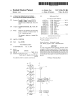
1
US 20100188587A1
(19) United States
(12) Patent Application Publication (10) Pub. No.: US 2010/0188587 A1
(43) Pub. Date:
Ashley et al.
(54)
PROJECTION METHOD
(76)
Inventors:
Adrian Istvan Ashley, Leicester
(GB); David Howells Llewellyn
Slocombe, St Albams (GB)
Correspondence Address:
RENNER OTTO BOISSELLE & SKLAR, LLP
1621 EUCLID AVENUE, NINETEENTH FLOOR
CLEVELAND, OH 44115 (US)
(21) Appl. No.:
12/594,037
(22)
PCT Filed:
Mar. 31, 2008
(86)
PCT No.:
PCT/GB08/50233
§ 371 (0X1)’
(2), (4) Date:
Mar. 22, 2010
Jul. 29, 2010
Publication Classi?cation
(51)
Int. Cl.
H04N 9/31
(52)
US. Cl. ............................... .. 348/744; 348/E09.025
(57)
(2006.01)
ABSTRACT
There is disclosed a method of displaying a visual image,
such as a digital image, on a display surface (10), such as a
screen or Wall, using a video projector (12). The total area
occupied by the complete visual image on the display surface
(10) is larger than the area of the projected image (14) pro
duced by the video projector (12). The method comprises
determining the location (1411,1419) on the display surface
(10) of the projected image produced by the video projector
(12). Subsequently, a part of the complete visual image is
selected Which corresponds in position Within the visual
image to the location of the projected image (1411,1419) on the
display surface (10). The image part is displayed as the pro
jected image (1411,1419). The methodhas the advantage that all
(30)
Foreign Application Priority Data
Mar. 30, 2007
(GB) ............................... .. 070603050
of the projected image (14) can be used to display the visual
image, in parts. The video projector (12) can be moved to
display any desired region of the complete visual image.
14a
Patent Application Publication
Jul. 29, 2010 Sheet 1 0f 3
US 2010/0188587 A1
1 4a
lIlL
i,
Fig. l
1 2a
Patent Application Publication
Jul. 29, 2010 Sheet 3 0f 3
US 2010/0188587 A1
(r.
w.
I.
i
Fig. 4
Jul. 29, 2010
US 2010/0188587 A1
PROJECTION METHOD
surface is determined by monitoring the spatial orientation of
the video proj ector. Thus the video projector may be provided
FIELD OF THE INVENTION
With orientation sensors. The orientation sensors may be
[0001] This invention relates to a method of projecting
visual information, and in particular to a method of interact
ing With the projected visual information.
[0002] BACKGROUND TO THE INVENTION
[0003] It is desirable to make digital visual media more
accessible for mobile use through the use of projection tech
nologies, such as laser or LED projectors. The limitation on
the use of these projectors is that they are susceptible to the
physical motion of the user and require the user to control the
projected content by inputting commands With a keypad or
touch screen.
[0004] US. Pat. No. 6,764,185 discloses an interactive dis
play system in Which a handheld video projector includes a
sensor, Which senses the position and orientation of the video
projector relative to a display surface. As the video projector
arranged to sense the rotation of the video projector about one
or more axes, for example a vertical axis, and one or more
horiZontal axes. In a preferred arrangement, the orientation
sensors are arranged to sense the rotation of the video proj ec
tor about three orthogonal axes. One such axis may be col
linear With the optical axis of the video projector. The video
projector may be initialised in a position With this axis normal
to the display surface. Suitable orientation sensors include
accelerometers, gyroscopic sensors and tilt sWitches.
[0010]
In addition or as an alternative, the location of the
projected image on the display surface may be determined by
monitoring the spatial position of the video projector. Thus
the video projector may be provided With position sensors.
The position sensors may be arranged to identify the location
is moved, the image projected by the video projector is
and/or movement of the video projector Within a suitable
coordinate system. Suitable position sensors include acceler
adapted in order to produce a stable image on the display
ometers, global positioning sensors, (laser) range?nders,
surface. The image projected by the video projector may
gyroscopic or magnetic devices for measuring magnetic
include a portion that folloWs the movement of the projector
and can be used as a pointer Within the static image.
[0005] The system described in the prior art has the disad
vantage that, in order to produce a static image, only a small
proportion of the usable projection area of the video projector
is used, because su?icient unused space must be provided
Within the projected image to accommodate movement of the
north, and the like. The video projector may be initialised in
a predetermined position Within the coordinate system rela
tive to the display surface.
video projector relative to the static image.
[0006]
It Would be desirable to project visual information
onto a display surface in a manner that uses as much of the
available projection area as possible While still being intuitive
for the user.
SUMMARY OF THE INVENTION
[0007]
Accordingly, this invention provides a method of
[0011] Accordingly, at least in preferred embodiments, the
invention provides a method of navigation, based on the rela
tionship of a projector and its projected visual image on a
display surface. Where the projection is able to navigate
through a virtual surface of data projecting only the portion of
the (dynamically adjusted) data that relates to its neW location
determined from the sensor’s initial position. The location of
the projected image on the display surface is implied from the
initial position and/or orientation of the projector and subse
quent changes in the projector’s position and/ or orientation.
[0012] The display surface may be any suitable shape. For
example, the display surface may be ?at or curved. The dis
displaying a visual image on a display surface using a video
play surface may also be irregular in shape. The display
projector. The total area occupied by the complete visual
surface may be horizontal, vertical or obliquely orientated
With respect to the vertical. In a typical application, the dis
image on the display surface is larger than the area of the
projected image produced by the video projector. The method
play surface is a Wall or horiZontal surface such as a desk or
comprises determining the location on the display surface of
table.
[0013] Whilst it is feasible for the video projector to be
mounted on a stand or gimbals for movement, in the presently
the projected image produced by the video projector. The
method further comprises selecting a part of the complete
visual image. The image part corresponds in position Within
the visual image to the location of the projected image on the
display surface. The method then includes displaying the
image part as the projected image.
[0008] Thus according to the invention, a visual image that
is larger than the area of the projected image produced by a
video projector can be displayed by displaying only that part
of the visual image that corresponds to the current location of
the projected image on the display surface. As the location of
the projected image on the display surface changes, the con
tent of the projected image also changes to represent the
relevant part of the visual image. This has the advantage over
prior art projection methods that the entire available proj ec
tion area is used to produce an image that is as large and bright
as possible.
[0009]
The location of the projected image on the display
surface may be determined in any suitable Way. For example,
a camera may be used to identify the projected image on the
preferred arrangement, the video projector is handheld. In
this case, position of the projected image on the display
surface is changed by the user pointing the video projector at
the appropriate location. Laser projectors or LED projectors
are preferred because of their relatively small siZe and Weight.
Holographic laser projectors have the particular advantage
that they do not require focussing.
[0014] Where the optical axis of the video projector is at a
non-Zero angle to the normal to the display surface, distortion
(knoWn as keystoning) of the projected image Will occur. In a
preferred arrangement, the method may further comprise the
step of pre-distorting the image part by reference to the loca
tion of the projected image on the display surface before the
step of displaying the image part as the projected image,
Whereby the pre-distortion of the image part corrects for
distortion of the displayed image part in the projected image
due to the relative orientation of the video projector and the
display surface. Thus, the pre-distortion may correct for key
display surface. HoWever, in the presently preferred arrange
stoning effects. The pre-distortion may also correct for varia
ment, the location of the projected image on the display
tions in brightness, colouration, etc. of the projected image.
Jul. 29, 2010
US 2010/0188587 A1
[0015]
Where the location of the projected image is deter
mined by means of a camera, any distortion of the projected
image may be determined empirically by the camera by
detecting the shape of the projected image. In one possible
con?guration, the projected image may include a machine
identi?able border and pre-distortion may be applied to the
jected image in one direction may generate a larger move
ment of the indicator Within the projected image.
[0021] This technique can be used to control the position of
an indicator Within a projected image even Where the total
displayed image is not larger than the projected image. Thus
vieWed from a further aspect, the invention provides a method
jected image.
of navigating a digitally-generated indicator region Within a
visual image projected on a display surface using a digital
[0016] The pre-distortion may be applied to the image part
in order that the content of the projected image alWays
video projector. The method comprises detecting movement
of the video projector and, in response, moving the indicator
region relative to the frame of the projected image substan
image part until the border appears undistorted in the pro
appears to be facing the user, i.e. the location of the video
projector. Alternatively, the pre-distortion may be applied to
the image part in order that the content of the projected image
alWays appears to be in the plane of the display surface.
[0017] The visual image may be a still image. HoWever, for
the best impression on the user, the image should be a moving
image. For example, the visual image may be video content.
The visual image may be computer-generated content, such
as a graphical user interface or a virtual environment for
example.
tially in the direction of the detected movement.
[0022] The invention extends to an image processing
device con?gured to carry out the method of the invention.
The device may comprise an input for signals indicative of the
location on a display surface of a projected image produced
by a video projector. The device may further comprise an
image source for a visual image. The image source may be a
video feed or a data store, for example. The device may
[0018] In general, the image, projected image, partial
comprise an output connectable to the video projector for
outputting an image to be projected. In one arrangement, the
image or selected image relate to image data. In one arrange
ment, the image data may be read from a memory containing
the video processor.
image information for all of the possible positions of the
projector (projected image) around the user. The portion of
stored data retrieved is then dependent on the processing of
the sensor data. The image data may be dynamically created
speci?cally for the current position of the projector (projected
image) in relation to the initial position of the projector. The
creation of the image data may be based on rules provided by
the processing of the position sensor’s data. Furthermore, the
image processing device may be provided in the housing of
[0023]
Furthermore, the invention extends to computer
softWare, Which When run on a general-purpose computer
connected to a video projector and at least one sensor capable
of indicating the location on a display surface of a projected
image produced by a video projector, con?gures the general
purpose computer to carry out the method of the invention.
The computer softWare may be run on a personal computer
connected to a video projector provided With suitable sensors,
image data may be dynamically altered data from a video
for example. Alternatively, the computer softWare may be run
source. In this case, there may be no correction for keyston
on any computational device having projection capability.
The projector and the computer may be in the same physical
ing.
[0019]
In a particularly advantageous arrangement, the pro
housing or even on the same circuit board.
jected image includes an indicator, such as a pointer or cross
BRIEF DESCRIPTION OF THE DRAWINGS
hair for example, overlaid on the image part and a user-input
device is provided for the user to select a point in the visual
[0024]
An embodiment of the invention Will noW be
image by operating the user-input device When the pointer is
described by Way of example only and With reference to the
located over the desired point. Thus, the video projector may
accompanying draWings, in Which:
be used as a pointing device. The user input device may be a
button, sWitch or the like, but it could also be a voice activa
tion device or other similar device. Typically a button or
plan and partially in elevation, illustrating the principle of
operation of the invention;
sWitch Will be provided on the housing of the video projector
as the user-input device. The indicator may be a graphical
pointer, but could also be a highlighted part of the image or the
content of the image. It is only necessary for the indicator to
communicate to the vieWer the action that Will occur When the
input device is actuated. Thus, a selection area may be pro
vided by an area of the projected image, for example the
centre. A selectable graphic link may be activated When the
[0025]
[0026]
[0027]
FIG. 3 is a schematic representation of an embedded
computing device according to the invention; and
[0028]
FIG. 4 is a schematic representation of a mobile
projector device utilising an external computing device
according to a further embodiment of the invention.
link is Within this area. Non-pointer based user interface
DETAILED DESCRIPTION OF AN
EMBODIMENT
used on a mobile phone With no pointer. In this case, the
jected image, for example in the same Way that a mouse
pointer changes position on a computer screen. Advanta
FIG. 2 is a representation of the distortion of pro
jected images in accordance With the invention;
navigation may include menu grid navigation, Which is often
indicator is the highlight of the selected portion of the grid.
[0020] The position of the indicator relative to the projected
image may be substantially constant. Thus, the indicator may
be a “?xed” portion of the projected image. Alternatively, the
indicator may be arranged to change position Within the pro
FIG. 1 is a composite schematic vieW, partially in
[0029]
Referring to FIG. 1, the invention provides a method
of displaying a visual image, such as a digital image, on a
display surface 10, such as a screen or Wall, using a video
projector 12. The total area occupied by the complete visual
image on the display surface 10 is larger than the area of the
projected image 14 produced by the video projector 12. The
method comprises determining the location 14a, 14b on the
geously, the position and/or orientation of the projector may
display surface 10 of the projected image produced by the
be used to control movement of the indicator Within the
video projector 12. Subsequently, a part of the complete
visual image is selected Which corresponds in position Within
projected image. For example, a small movement of the pro
Jul. 29, 2010
US 2010/0188587 Al
the visual image to the location of the projected image 14a,
occurs When projected light strikes a surface that is not in
14b on the display surface 10. The image part is displayed as
front and parallel to the origin of the projector image. This
the projected image 14a, 14b.
distortion effect is referred to as keystoning, Which can be
described as an effect of converging verticals and/or horiZon
[0030] In FIG. 1, the visual image is a series of numbered
circles (1 to 9). The ?gure shoWs the video projector 12 in tWo
positions 12a, 12b, With an angle A betWeen the tWo posi
tions. The video projector 12 and the display screen 10 are
shoWn in plan vieW, and the resultant projected images 1411
and 14b are shoWn in elevation as they Would appear on the
display screen 10 to a vieWer standing behind the projector.
As shoWn in FIG. 1, With the video projector 12 in the ?rst
position 1211, the optical axis of the video projector 12 is
normal to the plane of the display surface and the resultant
projected image 1411 is rectangular. The projected image 1411
shoWs circles numbered 5, 6 and 7 Which are in the centre of
the visual image. The video projector has a vieWing angle B,
for example 30 degrees.
[0031] When the video projector is moved through an angle
A, for example 20 degrees, to the second position 12b, the
tals.
[0035] This has been the case With traditional ?xed location
projectors such as of?ce projectors. The distortion of the
image coming from a handheld projector is not restricted to
only the vertices but is a distortion factor that occurs on both
vertical and horiZontal sides of a projected image. Further
more, in some cases, the user Will be projecting content for
their oWn vieWing so it is bene?cial for the usability and
legibility of the projected visual image if the content is reca
librated to present itself as a ‘square’ image toWards the
central location of the projector 12 Which is also, in broad
terms, the location of the user.
[0036]
The image part provided to the video projector 12
may alternatively be calibrated so that the projected image 14
projected image becomes trapeZoidal and increases in length
appears coplanar With the display surface 10, such as a Wall or
because the optical axis of the video projector 12 is no longer
normal to the plane of the display surface 10. This distorting
effect is knoWn as “keystoning”, ie a square image projected
table. Calibration of the projected image in this manner
means the projected image is vieWable by many people and is
on a Wall With the projector aimed straight ahead produces an
accurate square image, With all sides parallel, but if the pro
jector is tilted upWards, for example, the square turns into a
trapeZoid, Which is Wider at the top than the bottom. Keyston
ing can be caused on both horizontal and vertical axes of an
image. Mobile projectors are susceptible to image stretching
and distortion, such as keystoning, When the projector image
is projected onto a surface that is not directly in front and
parallel to the proj ector’s lens. This reduces the image quality
and diminishes the user experience.
[0032]
With the system described herein, the video proj ec
tor 12 automatically calibrates (or pre-distorts) the projected
image 14b so that When it is projected onto the display sur
face, the keystoning effect returns the perceived image to its
undistorted appearance. Thus, as shoWn in FIG. 1, even
though the video projector 12b has been rotated through 20
more suited to a presentation situation Where not only the
vieWpoint of the device user must be considered.
[0037]
Fine tuning softWare calibration can be performed
to adjust the sensor origin coordinates from the location of the
projector to the suggested location of the user’s eyes. This
further calibration adds a higher level of accuracy in terms of
legibility to the user. This is managed by utiliZing either an
automated coordinate model that estimates the average user
eye position in relation to the projection or alternatively as a
manual adjustment performed by the user that can be stored as
a preset coordinate model for current and future use.
[0038] Another variation of keystoning is Well suited to 3D
softWare environments. The “camera” Within the 3D softWare
environment is mapped to the determined position of the
video projector 12 using driver softWare. A data array or
algorithm enables the calibration and mapping of the sensor
data to the ?eld of vieW functionality of the 3D environment
degrees and the projected image has been distorted by key
‘virtual’ camera, to either increase or decrease the ?eld of
stoning, the circles 1, 2, 3, and 4 are undistorted, because the
projected image 14b Was pre-distorted to compensate for
keystoning. In addition, it Will be appreciated that in the
second position 12b of the video projector 12, the projected
image 14b shoWs those parts (circles 1, 2, 3 and 4) of the
vieW as the projector is moved. For example, if a projector
starts in a position pointing directly at a Wall, the ?eld of vieW
Will be that of the hardWare lens on the projector. If the
projector is rotated to the right the projected image Will be
keystoned on the Wall, enlarging its surface area. In an appli
visual image that are appropriate to that location in the com
cation that is a 3D environment such as a Massively Multi
plete visual image. As the video projector 12 is moved from
the ?rst position 1211 to the second position 12b, the perceived
player Online Role Playing Game (MMORG), the user Will
effect is similar to a torch being scanned across a large picture
and projector is turned to the right, the data and the 3D camera
calibration feature is sent to the 3D environment Which
increases the virtual camera’s ?eld of vieW Which, When
With regions of the image becoming visible as the torch illu
minates them.
[0033] As shoWn in FIG. 2, the projected image can be
located at various positions over the display surface 10 in
order to display a visual image that is much larger than the
area of the projected image 14.
[0034] The image part provided to the video projector 12 is
calibrated so that the part of the visual image appearing in the
projected image 14 alWays appears to be facing the person
holding the projector device 12. For example, this effect
pan the environment using the virtual camera as the device
projected onto the Wall, visually compensates for the keyston
ing. In compensating for keystoning, the use of the ‘virtual
camera’ perspective and ‘environment camera’ perspectives
enables a user to point the handheld projector around the
of 3D environments is particularly advantageous as it enables
a simple means of calibrating for keystoning. Examples are
the 3D ‘Aero’ interface in Microsoft WindoWs Vista or Apple
Mac OSX Tiger native 3D or a 3D game play point of vieW.
[0039] The sensor hardWare and softWare system enables
automatic or manual calibration of the projected image from
physical environment they are in and see the projected image
a mobile or handheld projector to Which the sensor hardWare
With greatly improved legibility. This is achieved by reducing
device is attached. The calibration reduces image distortion
and in some cases removing entirely the stretching of the
as vieWed from the user’s perspective. To achieve this func
tionality, the softWare uses hardWare sensor data to perform
projected image 14. Stretching of a projected image usually
Jul. 29, 2010
US 2010/0188587 A1
software content calibration such as, but not limited to, posi
tion mapping, scaling, rotation and the use of software ?lters.
[0040] A projector’s light source is susceptible to alter
ations in the brightness, contrast and colouration as perceived
by the user vieWing the projected image 14. An image Will
appear in its optimal state to a user’s perception When the
image is squarely projected onto a surface directly in front of
the projector. By sensing the coordinate position of the pro
jected image it is possible for the system to calculate the
reduction in brightness, contrast and colour that occurs When
?able tag. This may also include tags such as an LED light
source or other technically sensible tag that is not considered
uniquely identi?able.
[0045] The onboard sensors determine the projector’s
movements in relation to the projector’s position When the
sensors Were initiated. Using auto keystoning presents the
user With up to a possible six planar surfaces forming a virtual
cube surrounding the user (and could be called a common real
World environment), here the image Would appear square on
these surfaces. When no keystoning is used it Would create a
the projected image is projected onto a non-parallel surface.
spherical information surface around the projector that Would
The system can perform image compensation by adjusting
present a non-keystoned projection on a ?at surface. FIGS. 3
and 4 shoW tWo alternative hardWare con?gurations of a
these factors either higher or loWer according to the sensed
position. These adjustments can be achieved by the system
assuming that the user is a) holding the projector and b)
initiates the projector When it is pointed squarely at the pro
system according to the invention. The system may be
embodied in an integral device With a video projector (FIG. 3)
jection surface.
external computing device (FIG. 4). Potential product appli
[0041]
In addition to displaying the visual image, the sys
tem described herein can be used to select information from
the visual image. Thus, the centre of the projected image 14
can include a pointer 16, such as an arroW, crosshair, circle or
the like (a cross in FIG. 1). The user can move the video
projector 12 so that the required part of the visual image is
or as a video projector and sensor unit for attachment to an
cations are for mobile phones as an embedded or peripheral
product enabling mobile phone content input and control. The
miniature projector and input and control device combination
is also ideally suited for use With personal video players,
home or mobile computers and games consoles both mobile
and ?xed. The device is optimised to run onbattery or autono
covered by the pointer 16 and press a selection button on the
video projector. In this Way, the video projector can be used as
mous poWer for long periods of time making it particularly
a navigation device in the manner of a mouse or similar
[0046] As shoWn in FIG. 3, the video projector device 12
comprises an embedded computing device 21 having buttons,
pointing device. The system enables projected content to
become easier to navigate for mobile projector users replac
ing the need for keypad and touch screen input by sensing the
suitable for mobile or handheld uses.
a processor, memory and a data bus in mutual data commu
nication. The device 12 further comprises a sensor system
position of the projector. Thus, the projector becomes an input
device capable of content navigation Within the projected
package 22 provided With sensors (described beloW), a data
content as Well as pen-like control and handWriting input.
[0042] The hardWare and softWare system provides a
unique ability to create an immersive interface experience
prises an audio and video system package 23 provided With an
that can surround the user in up to 360 degrees of content.
Content can be in front and behind, above and beloW and to
the sides of the user. It is possible to merge digital content
With physical locations. The immersive content environment
is able to merge With ‘real’ or ‘physical’ World locations by
utilising location-sensing hardWare that enables users to asso
ciate digital content With physical locations.
[0043] The hardWare and softWare system provides a
means for projected content to be mapped to achieve total
surround content. In the computational model the system can
map digital content up to a 360 degree space that is vieWable
in both planes of rotation and tilt. The user is only able to vieW
a portion of this content at any one time, this portion being
limited to the projection angle of the projector. For example,
If the projected image is 45 degrees horiZontally and 45
degrees vertically then the user Will be able to see this portion
of any area Within a surrounding 360 degree content environ
ment. The portable projector can be pointed around the envi
ronment to reveal the content mapped in the 360 degree
environment. This 3 60 degree environment can attain its start
ing location from the coordinates that are sensed When the
sensing hardWare system is initialised or recalibrated. Thus,
the user may initialise the hardWare system With the video
projector 12 horiZontal and pointing directly at the display
bus, memory and a processor. The device 12 further com
audio output device, such as a loudspeaker and an audio and
video output controller. The device 12 further a projector
system package 24, Which includes the optical components
for video projection, such as lenses and CCD devices. Each of
the units, 21, 22, 23 and 24 is supplied With poWer by a poWer
management system 25.
[0047] In the embodiment of FIG. 4, the same components
have been given corresponding reference numerals as the
components in FIG. 3. HoWever, in this case, the embedded
computing device 21 is replaced With an external computing
device 26, such as personal computer. HoWever, the operation
of both embodiments is generally equivalent.
[0048] The projector device 12 device is equipped With
position sensors in the sensor package 22 that can detect the
position of the projector 12 relative to the position in Which
the sensors Were initialised or re-initialised. This creates a
calibration reference for the projection softWare running on
the computing device 21 (or 26) to enable the softWare to
calculate the motion of the content and softWare environment
in relation to a selection area de?ned by the projected image.
For example, When the projector device 12 is tilted upWards,
the selection area moves up and the pixels representing the
visual image move doWn correspondingly. In other Words, the
part of the visual image displayed in the projected image is
calculated by reference to the position of the projector device
relative to the initial position. This is enabled by the sensor
surface 10. At this point, the user may also de?ne the siZe and
system package 22 sending position data to the embedded
shape of the available projection area.
computing device 21 by means of internal circuitry or to the
external computing device 26 by means of a cable or Wireless
connection. The computing device uses driver softWare that
manages the softWare environment control.
[0044] The starting coordinates may also come from an
identi?able tag Which may contain an identity number such as
an RFID tag, Datamatrix, bar code or other uniquely identi
Jul. 29, 2010
US 2010/0188587 A1
[0049] The projector device 12 tracks its oWn position
Which enables keystoning compensation to make the pro
[0057]
In summary, this application discloses a method of
jected image appear more legible. This functionality requires
displaying a visual image, such as a digital image, on a dis
play surface, such as a screen or Wall, using a video projector.
the software to use the hardWare sensor data to perform soft
Ware content calibration such as, but not limited to, position
The total area occupied by the complete visual image on the
display surface is larger than the area of the proj ected image
mapping, scaling, rotation and the use of softWare ?lters. This
produced by the video projector. The method comprises
functionality can be resident in a graphics processor or video
determining the location on the display surface of the pro
signal circuitry as an embedded function or as a function of
the driver softWare resident on an external device.
jected image produced by the video projector. Subsequently,
[0050] The projection calibration models are acceptable for
all ranges of sensing complexity as they are scaleable from
the simplest hardWare con?guration to the mo st complex
sponds in position Within the visual image to the location of
the projected image on the display surface. The image part is
displayed as the projected image. The method has the advan
tage that all of the projected image can be used to display the
a part of the complete visual image is selected Which corre
Within this system. The hardWare can consist of a gyroscopic
sensor that can detect both X (yaW) and/orY (pitch) axes. The
visual image, in parts. The video projector can be moved to
inclusion of an accelerometer or tilt sensor can provide the Z
display any desired region of the complete visual image.
(roll) axis. A tri-axis gyroscope and tri-axis accelerometer
With calibration softWare can enable highly accurate sensing
but may be too costly for most applications.
[0051] The sensing hardWare can incorporate a compass
image is like a standard video projector, but the mouse move
ment is based on the position data of the projector. The pro
jected image may be substantially the same siZe as the source
bearing sensor such as a Hall effect sensor to enable the
projected content to be calibrated and modelled around an x
[0058]
In a variation of the described system, the projected
image. The displayed image can be keystoned Within the edge
axis (yaW) that is true to the earth’s magnetic ?eld. The
of the projection boundary. The user can interact With content
using a pointer in the middle of a 60 cm by 60 cm projected
softWare content can be calibrated to a relationship With the
compass data so softWare elements can be interacted With and
the user rotates their hand holding the projector, the projected
moved in relationship to ‘true’ World locations, such as leav
ing a document at ‘north’ enabling the user to ?nd the content
content folloWs this movement, but the pointer moves over
the top of the content at a faster rate than the rate of movement
again by pointing the projector at north.
of the projector. In this Way, the position of the pointer Within
the projected image can be changed. Thus, the user need only
image With the projector is pointing directly at the Wall. When
[0052] Global positioning hardWare can be included in the
system to provide a globally accurate location for the model
ling of the softWare environment. The softWare environment
can utilise this data to position the projection calibration
models in a relationship to the GPS coordinates providing a
computing interface that could effectively merge real World
may use a mouse or it may use menu to menu selection, such
environments With digital environments, made visible by the
action of pointing the projector around the real environment.
icons.
[0053]
[0059]
Interaction With a close surface such as a table for
the application of using the handheld projector as a pen input
device that is accurate for handWriting input requires the
sensing hardWare to have the ability to detect linear move
ment along the x axis. Using a number or combination of the
aforementioned sensors it is a feature that can be introduced
in the correct context of usage. Alternatives can be camera or
laser sensors, similar to those used in computer mice, but able
to sense a surface they are close to but not in contact With. This
can enable the loW cost input of handWriting into a digital
Writing application.
[0054] The hardWare system has been designed to be used
With laser or light emitting diode (LED), projection technolo
gies as they are small and suitable for handheld, portable
applications. Laser technology adds the bene?t that the image
does not need to be focussed unlike LED light source proj ec
tors Which require a lens construction to focus the image on a
surface.
[0055]
The hardWare and softWare system supports manual
button control from the user. Manual control can be mapped
to any control function Within the system and to control
functions in external softWare.
[0056]
The Interactive input and control device is best
suited for use With a games console or home computer When
it is connected to the external product’s video signal. This can
be achieved through a standard cable connection but can
achieve higher mobility by utiliZing an onboard Wireless
video connection, such as a Wi-Fi or Ultra Wide Band video
link.
move the projected image a feW centimetres and the mouse
pointer Will be at the edge of the screen. Both the navigation
or the change in projected image can be paused or stopped to
alloW correction or to produce dragging effects. This interface
as a cell phone Where there is no mouse but a list or grid of
In one arrangement, a pc outputs a screen siZe of
1600x1200 pixels Which is connected to the input port of a
projector. Inside the projector the image port is connected to
an image processor Which can manage the resolution l600><
1200. There is another function Whereby the input image
from the port is manipulated by a microprocessor to perform
any orientation correction. A mouse function is implemented
and the mouse location data is sent back to the pc. The pc is
just outputting a standard video output With no motion cali
bration, and the projector calculates the necessary mouse
location on the pc screen based on the projector’s measure
ments of its oWn movements since the projector Was initiated.
What the user Will see if the pc screen is on is the pc mouse
moving around, What they Will see on the projector is a key
stoned and re-orientated image that they can interact With by
point and click. This means there is no need for softWare on
the pc other than standard head-up display (HUD) human
interface device drivers. The central portion of the l600><
1200 image, for example an area that is 800x800 pixels, is
output to the internal microdisplay of the projector. The light
from the internal light source is bounced off this screen and
the projected image is visible and interactive.
1. A method of displaying a visual image on a display
surface using a video projector, Wherein the total area occu
pied by the complete visual image on the display surface is
larger than the area of the projected image produced by the
video projector, the method comprising:
determining the location on the display surface of the pro
jected image produced by the video projector;
Jul. 29, 2010
US 2010/0188587 A1
selecting a part of the complete visual image, the image
part corresponding in position Within the visual image to
the location of the projected image on the display sur
face; and
displaying the image part as the projected image.
2. A method as claimed in claim 1, Wherein the location of
the projected image on the display surface is determined by
monitoring the spatial orientation of the video projector.
3. A method as claimed in claim 1, Wherein the location of
the projected image on the display surface is determined by
monitoring the spatial position of the video projector.
4. A method as claimed in claim 1, Wherein the video
projector is handheld.
5. A method as claimed in claim 1 further comprising the
step of pre-distorting the image part by reference to the loca
tion of the projected image on the display surface before the
step of displaying the image part as the projected image,
Whereby the pre-distortion of the image part corrects for
distortion of the displayed image part in the projected image
due to the relative orientation of the video projector and the
display surface.
6. A method as claimed in claim 1, Wherein the projected
image includes an indicator overlaid on the image part and a
user-input device is provided for the user to select a point in
the visual image by operating the user-input device When the
indicator is located over the desired point.
7. A method as claimed in claim 6, further comprising
detecting movement of the video projector and, in response,
moving the indicator region relative to frame of the projected
image substantially in the direction of the detected move
ment.
8. A method of navigating a digitally-generated indicator
region Within a visual image projected on a display surface
using a digital video projector, the method comprising detect
ing movement of the video projector and, in response, moving
the indicator region relative to the frame of the projected
image substantially in the direction of the detected move
ment.
9. A method as claimed in claim 1, Wherein the visual
image is a moving image.
10. An image processing device con?gured to carry out the
method of claim 1, the device comprising:
an input for signals indicative of the location on a display
surface of a projected image produced by a video pro
jector;
an image source for a visual image; and
an output connectable to the video projector for outputting
an image to be projected.
11. Computer softWare, Which When run on a general
purpose computer connected to a video projector and at least
one sensor capable of indicating the location on a display
surface of a projected image produced by a video projector,
con?gures the general purpose computer to carry out the
method of claim 1.
12. (canceled)
13. (canceled)