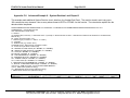
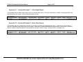
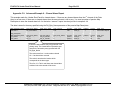
1
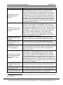
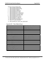
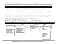
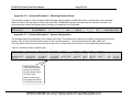
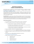
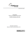
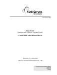
A Sierra Monitor Company
Driver Manual
(Supplement to the FieldServer Instruction Manual)
FS-8700-74 Veeder-Root
APPLICABILITY & EFFECTIVITY
Effective for all systems manufactured after May 1, 2001
Driver Version:
1.01
Document Revision: 3
FS-8700-74 Veeder Root Driver Manual
Table of Contents
TABLE OF CONTENTS
1. Veeder-Root Driver Description ..........................................................................................3
2. Driver Scope of Supply ........................................................................................................4
2.1.
Supplied by FieldServer Technologies for this driver ...................................................4
2.2.
Provided by the Supplier of 3rd Party Equipment ..........................................................4
2.2.1. Required 3rd Party Hardware.....................................................................................4
3. Hardware Connections ........................................................................................................5
4. Configuring the FieldServer as a Veeder-Root Client.......................................................6
4.1.
Data Arrays...................................................................................................................6
4.2.
Client Side Connections ...............................................................................................7
4.3.
Client Side Nodes .........................................................................................................8
4.4.
Client Side Map Descriptors .........................................................................................8
4.4.1. FieldServer Specific Map Descriptor Parameters .....................................................8
4.4.2. Driver Specific Map Descriptor Parameters ..............................................................9
4.4.3. Timing Parameters ....................................................................................................9
4.4.4. Map Descriptor Example 1 - Alarms........................................................................10
4.4.5. Map Descriptor Example 2 - Inventory ....................................................................11
4.4.6. Map Descriptor Example 3 – Most Recent Delivery Report ....................................12
5. Configuring the FieldServer as a (Veeder-Root Driver) Server......................................13
Appendix A. Advanced Topics ............................................................................................14
Appendix A.1. Data Type and Required Lengths .................................................................14
Appendix A.2. Supported Functions .....................................................................................15
Appendix A.3. Alarm Types ..................................................................................................16
Appendix A.4. Security Codes ..............................................................................................20
Appendix B. Trouble Shooting and Driver Error Messages .............................................21
Appendix B.1. Driver Stats....................................................................................................24
Appendix B.2. Table of Module Types..................................................................................25
Appendix C. Advanced Map Descriptor Examples............................................................26
Appendix C.1. Advanced Example 1 – Polling for Tank / Sensor / Input / Relay / Device
Status
26
Appendix C.2. Advanced Example 2 – Resetting Remote Alarms .......................................27
Appendix C.3. Advanced Example 3 – System Configuration ..............................................27
Appendix C.4. Advanced Example 4 – System Diagnostics.................................................28
Appendix C.5. Advanced Example 5 – System Revision Level Report ................................29
Appendix C.6. Advanced Example 6 – System Revision Level Report II .............................30
Appendix C.7. Advanced Example 7 – Stick Height Report ................................................31
Appendix C.8. Advanced Example 8 – Active Alarm Report ................................................31
Appendix C.9. Advanced Example 9 – Cleared Alarm Report .............................................32
FieldServer Technologies 1991 Tarob Court Milpitas, California 95035 USA Web:www.fieldserver.com
Tel: (408) 262-2299 Fax: (408) 262-9042 Toll_Free: 888-509-1970 email: [email protected]
FS-8700-74 Veeder Root Driver Manual
1.
Page 3 of 33
Veeder-Root Driver Description
The Veeder-Root Serial Driver allows the FieldServer to transfer data to and from devices over
either RS-232 or RS-485 ports using Veeder-Root protocol as defined in Veeder Root
Document 576013-635 Revision J.
The FieldServer emulates a Client.
The Veeder-Root Serial Driver is a poll response driver. Only one query or command can be
processed at a time.
A limited set of the queries and commands defined in the protocol specification have been
implemented. The reason for the limitation is two-fold. Firstly, not all commands/queries will
have any meaning to a downstream device as they are principally defined to configure the
Veeder-Root Device. Secondly some commands return very complex data sets which cannot
be processed in a method suitable for loading into the FieldServer’s Data Arrays.
The driver is capable of exposing its communications statistics. This can be useful if you wish
to monitor them using a downstream device. In this way you can ensure that you are using
valid data and can generate alarms if communication problems arise.
FieldServer Technologies 1991 Tarob Court Milpitas, California 95035 USA Web:www.fieldserver.com
Tel: (408) 262-2299 Fax: (408) 262-9042 Toll_Free: 888-509-1970 email: [email protected]
FS-8700-74 Veeder Root Driver Manual
2.
Page 4 of 33
Driver Scope of Supply
2.1.
Supplied by FieldServer Technologies for this driver
FieldServer Technologies
PART #
FS-8915-10
FS-8917-01
FS-8700-74
2.2.
Description
UTP cable (7 foot) for RS-232 use
RJ45 to DB25M connection adapter
Driver Manual.
Provided by the Supplier of 3rd Party Equipment
2.2.1.
PART #
Required 3rd Party Hardware
DESCRIPTION
Veeder-Root Panel
FieldServer Technologies 1991 Tarob Court Milpitas, California 95035 USA Web:www.fieldserver.com
Tel: (408) 262-2299 Fax: (408) 262-9042 Toll_Free: 888-509-1970 email: [email protected]
FS-8700-74 Veeder Root Driver Manual
3.
Page 5 of 33
Hardware Connections
The FieldServer is connected to the Veeder-Root Panel as shown below.
Configure the Veeder-Root Panel according to manufacturer’s instructions.
TLS-350
8917-07
RJ45 CAT 5 Cable
Connect to
RS232 port P1-P8
P8
P7
R1
P1
Rx
Tx
P2
Rx
Tx
P3
Rx Tx
P4
Rx Tx
P5
Rx Tx
P6
Rx Tx
N1
R2
RS485
P7
Rx Tx
P8
Rx Tx
R1
Rx
Tx
R2
Rx
Tx
Net 1
Net 2
Tx Rx Con
Tx Rx Con
N2
10 Base T
ETHERNET
Pwr
P6
Run
P5
Act
P4
RS232
Sys
P3
P2
Com
P1
FieldServer
8917-07 WIRE LIST
FIELDSERVER
FUNCTION
RX
CTS
DSR
GND
DTR
RTS
TX
FROM
TO
RJ45-01
RJ45-02
RJ45-03
RJ45-04
RJ45-06
RJ45-07
RJ45-08
COLOR
DB25M-02
DB25M-05
DB25M-08
DB25M-07
DB25M-20
DB25M-06
DB25M-03
WHITE
BROWN
YELLOW
GREEN
BLACK
ORANGE
BLUE
(408)-262-2299
VEEDER ROOT
CONNECTION DIAGRAM
BASE NAME:
FILE NAME: FS-T28700-74 .VSD
DATE: 1/17/02
BY:
MN
FieldServer Technologies 1991 Tarob Court Milpitas, California 95035 USA Web:www.fieldserver.com
Tel: (408) 262-2299 Fax: (408) 262-9042 Toll_Free: 888-509-1970 email: [email protected]
FS-8700-74 Veeder Root Driver Manual
4.
Page 6 of 33
Configuring the FieldServer as a Veeder-Root Client
For a detailed discussion on FieldServer configuration, please refer to the FieldServer
Configuration manual. The information that follows describes how to expand upon the factory
defaults provided in the configuration files included with the FieldServer.
This section documents and describes the parameters necessary for configuring the FieldServer
to communicate with a Veeder-Root Device.
The configuration file tells the FieldServer about its interfaces, and the routing of data required.
In order to enable the FieldServer for Veeder-Root Driver communications, the driver
independent FieldServer buffers need to be declared in the “Data Arrays” section, the
destination device addresses need to be declared in the “Client Side Nodes” section, and the
data required from the Servers needs to be mapped in the “Client Side Map Descriptors”
section. Details on how to do this can be found below.
Note that in the tables, * indicates an optional parameter, with the bold legal value being the
default.
4.1.
Data Arrays
Section Title
Data_Arrays
Column Title
Function
Data_Array_Name
Provide name for Data Array
Data_Format
Provide data format. Each Data
Array can only take on one format.
Number of Data Objects. Must be
larger than the data storage area
Data_Array_Length
required for the data being placed in
this array.
Legal Values
Up to 15 alphanumeric
characters
FLOAT, BIT, UInt16, SInt16,
Packed_Bit, Byte,
Packed_Byte, Swapped_Byte
1-10,000
Example
// Data Arrays
//
Data_Arrays
Data_Array_Name,
DA_AI_01,
DA_AO_01,
DA_DI_01,
DA_DO_01,
Data_Format,
UInt16,
UInt16,
Bit,
Bit,
Data_Array_Length
200
200
200
200
FieldServer Technologies 1991 Tarob Court Milpitas, California 95035 USA Web:www.fieldserver.com
Tel: (408) 262-2299 Fax: (408) 262-9042 Toll_Free: 888-509-1970 email: [email protected]
FS-8700-74 Veeder Root Driver Manual
4.2.
Page 7 of 33
Client Side Connections
Section Title
Connections
Column Title
Port
Function
Specify which port the device is
connected to the FieldServer
Baud*
Specify baud rate
Parity*
Data_Bits*
Stop_Bits*
Specify parity
Specify data bits
Specify stop bits
Legal Values
P1-P8, R1-R21
300 – 9600, standard baud rates
only – Vendor limitation.
Even, Odd, None
7, 8
1, 2
Protocol
Specify protocol used
Handshaking* Specify hardware handshaking
Poll Delay*
Time between internal polls
Vroot, Veeder
None
0-32000 seconds, 1 second
Example
//
Client Side Connections
Connections
Port,
P1,
Baud,
9600,
Parity,
None,
Protocol,
Vroot,
Handshaking,
None,
Poll_Delay
0.100s
1
Not all ports shown are necessarily supported by the hardware. Consult the appropriate Instruction
manual for details of the ports available on specific hardware.
FieldServer Technologies 1991 Tarob Court Milpitas, California 95035 USA Web:www.fieldserver.com
Tel: (408) 262-2299 Fax: (408) 262-9042 Toll_Free: 888-509-1970 email: [email protected]
FS-8700-74 Veeder Root Driver Manual
4.3.
Page 8 of 33
Client Side Nodes
Section
Title
Nodes
Column
Title
Node_Name
Node_ID
Protocol
Port
Function
Legal Values
Up to 32 alphanumeric
characters
This commonly used parameter is not required for this driver.
Specify protocol used
Vroot, Veeder
Specify which port the device is connected
to the FieldServer
P1-P8, R1-R22
Provide name for node
Only one node per port.
This parameter is only required if security
is enabled on the Veeder-Root device.
In this case the route must be set to
contain the 6 digits that form the security
code.
*Route
a.b.c.d.e.f
a,b,c,d,e,f must be decimal
digits in the range 0 to 9.
Example. If the security code is 556741
then enter route as
5.5.6.7.4.1
Example
//
Client Side Nodes
Nodes
Node_Name,
VR_Node1 ,
4.4.
Protocol,
Vroot ,
Port
P1
Client Side Map Descriptors
4.4.1.
FieldServer Specific Map Descriptor Parameters
Column Title
Function
Map_Descriptor_Name Name of this Map Descriptor
Data_Array_Name
Name of Data Array where
data is to be stored in the
FieldServer
Data_Array_Location
Starting location in Data Array
Function
Function of Client Map
Descriptor
Legal Values
Up to 32 alphanumeric
characters
One of the Data Array names
from “Data Array” section
above
0 to maximum specified in
“Data Array” section above
RDBC, WRBC, WRBX
2
Not all ports shown are necessarily supported by the hardware. Consult the appropriate Instruction
manual for details of the ports available on specific hardware.
FieldServer Technologies 1991 Tarob Court Milpitas, California 95035 USA Web:www.fieldserver.com
Tel: (408) 262-2299 Fax: (408) 262-9042 Toll_Free: 888-509-1970 email: [email protected]
FS-8700-74 Veeder Root Driver Manual
4.4.2.
Page 9 of 33
Driver Specific Map Descriptor Parameters
Column
Title
Function
Node_Name
Name of Node to fetch data from
Data_Type
Data type
Legal Values
One of the node names
specified in “Client Node
Descriptor” above
System, Tank, Liquid Sensor,
Vapor Sensor, Input,
Volumetric Line, Groundwater
Sensor, Type-B Sensor,
Universal Sensor, Auto-Dial,
Mech. Dispenser, Elec.
Dispenser, Product, Press.
Line, External, WPLLD
The address is used to specify the
Tank/Sensor/Input /Relay … Number to
be used in the poll. For some data
types the address has no meaning and
should be set to 1.
*Address¥
Veeder-Root Tanks / Sensors … are
numbered from 1. The maximum tank
number is 12 and the maximum sensor
number if 64.
0, 1, 2, 3…
When zero is used as the value of the
address then (in most cases) the driver
polls for all Tanks/ Sensors belonging
to that data type. This is discussed in
the Advanced Topics Section.
Length of Map Descriptor
Length¥
4.4.3.
The length is used to tell the driver how
many elements of the Data Array are
under the control of the Map Descriptor.
This is important because the driver
uses the length to, for example, clear
Data Array elements when a
Tank/Sensor has no alarms.
Timing Parameters
Column Title
Scan_Interval
¥
1 - 1000
Function
Rate at which data is polled
Legal Values
>0.1s
See Appendix A.1 for Data Type, Address and Length Limitations.
FieldServer Technologies 1991 Tarob Court Milpitas, California 95035 USA Web:www.fieldserver.com
Tel: (408) 262-2299 Fax: (408) 262-9042 Toll_Free: 888-509-1970 email: [email protected]
FS-8700-74 Veeder Root Driver Manual
4.4.4.
Page 10 of 33
Map Descriptor Example 1 - Alarms.
This example provides one Map Descriptor to poll for alarm data and many Map Descriptors to store the response from the poll. One
Map Descriptor is required for each tank/sensor/input/device defined for the system. The address of each of these passive Map
Descriptors must correspond to the tank/sensor/input/device number. For example, where 5 tanks are defined as tanks 1,2,3,6,7
then 5 Map Descriptors with the data type ‘Tank’ are required and the address of each of these 5 Map Descriptors must be set to
1,2,3,6,7. The length parameter tells the driver how much array space is reserved for each tank/sensor… for storing alarms.
Map_Descriptors
Map_Descriptor_Name,
Poller
Map_Descriptors
Map_Descriptor_Name,
Sys_alms01
,
Tank_Alms1
,
LiqSensor_Alm1,
VaporSens_Alm1,
Input_Alm1
,
VolLine_Alm1 ,
GWater_Alms1 ,
TypeB_SensALm1 ,
Univ_SensAlm1 ,
AutoDial_Alms1 ,
MechDisp_Alm1 ,
ElecDisp_Alm1 ,
Product_Alms1 ,
PressLine_Alm1 ,
External_Alm1 ,
WPLLD_Alms1 ,
Only the Map
Descriptor used to
generate the poll
requires a scan
interval.
scan_interval,
1.0s
,
Data_Array_Name,
DA_101
,
Data_Array_Offset,
0
,
Function,
rdbc ,
node_name,
Node_A ,
Address,
1
,
Length,
30 ,
Data_Array_Name,
DA_S1
,
DA_T1
,
DA_L1
,
DA_V1
,
DA_I1
,
DA_O1
,
DA_G1
,
DA_B1
,
DA_U1
,
DA_F1
,
DA_M1
,
DA_E1
,
DA_P1
,
DA_R1
,
DA_X1
,
DA_W1
,
Data_Array_Offset
0
,
0
,
0
,
0
,
0
,
0
,
0
,
0
,
0
,
0
,
0
,
0
,
0
,
0
,
0
,
0
,
Function,
passive ,
passive ,
passive ,
passive ,
passive ,
passive ,
passive ,
passive ,
passive ,
passive ,
passive ,
passive ,
passive ,
passive ,
passive ,
passive ,
node_name,
Node_A ,
Node_A ,
Node_A ,
Node_A ,
Node_A ,
Node_A ,
Node_A ,
Node_A ,
Node_A ,
Node_A ,
Node_A ,
Node_A ,
Node_A ,
Node_A ,
Node_A ,
Node_A ,
Address,
1
,
1
,
1
,
1
,
1
,
1
,
1
,
1
,
1
,
1
,
1
,
1
,
1
,
1
,
1
,
1
,
Length,
30 ,
30 ,
30 ,
30 ,
30 ,
30 ,
30 ,
30
30 ,
30 ,
30 ,
30 ,
30 ,
30 ,
30 ,
30 ,
Data_Type
System
Tank
Liquid Sensor
Vapor Sensor
Input
Volumetric Line
Groundwater Sensor
Type-B Sensor
Universal Sensor
Auto-Dial
Mech. Dispenser
Elec. Dispenser
Product
Press. Line
External
WPLLD
These Map
Descriptors are
passive because
they do not
generate
messages. They
are used to store
data returned by
the system status
poll.
The address must
correspond to the
tank/sensor/input/device
number.
One Map Descriptor
required for each
tank/sensor/input/device.
Data_Type,
System Status
The length parameter tells the driver how much array space must be reserved
for storing alarms for a given tank/sensor/input/device.
When an alarm occurs for tank 1 the driver stores the alarm type by setting
the array position corresponding to the alarm type to a non-zero value as well
as setting the first element of the reserved space non-zero as a summary.
See Table 6.3 for alarm type numbers and descriptions.
Example: Tank 1 has two alarms
02 = Tank Leak Alarm
05 = Tank Low Product Alarm
The driver sets array DA_T1 as follows
Index=0 : Value=1 (Summary)
Index=2 : Value=2 (Leak)
Index=5 : Value=5 (Product)
FieldServer Technologies 1991 Tarob Court Milpitas, California 95035 USA Web:www.fieldserver.com
Tel: (408) 262-2299 Fax: (408) 262-9042 Toll_Free: 888-509-1970 email: [email protected]
FS-8700-74 Veeder Root Driver Manual
4.4.5.
Page 11 of 33
Map Descriptor Example 2 - Inventory
This example illustrates how you can poll for Tank Inventory Data. You need one Map Descriptor for each tank. Change the address
to correspond to the tank number. The Length parameter DOES NOT tell the driver how many tanks to process but it does tell the
driver how much storage space to reserve for storing the inventory data. The inventory data is stored as follows.
Index
0.
1.
2.
3.
4.
5.
6.
7.
8.
Contents
Product Code (Example Array value = 49 indicates product code = ASCII ‘1’)
Tank Status (Bit 1 - (LSB) Delivery in Progress, Bit 2 - Leak Test in Progress, Bit 3 - Invalid Fuel Height Alarm (MAG Probes Only))
Volume
TC Volume
Ullage
Height
Water
Temperature
Water Volume
.
Map_Descriptor_Name,
InventoryPoll1,
Reading the
inventory requires
an active Map
Descriptor.
Data_Array_Name,
DA_INVENTORY ,
Data_Array_Offset
0
,
Set the address equal to the
tank number. One Map
Descriptor per tank.
Function,
rdbc ,
Scan_Interval,
1.0s
,
node_name,
Node_A ,
Address,
1
,
Length,
10 ,
This is the minimum number of Data
Array elements required to store
inventory data.
Tanks 1’s data will be stored in the
array DA_INVENTORY starting at the
zero’th element (offset=0) and 10
elements of the array are reserved for
this data.
FieldServer Technologies 1991 Tarob Court Milpitas, California 95035 USA Web:www.fieldserver.com
Tel: (408) 262-2299 Fax: (408) 262-9042 Toll_Free: 888-509-1970 email: [email protected]
Data_Type
In-Tank Inventory
Setting the data type
generates the
correct poll. Ensure
that spelling,
periods, hyphens in
exactly the same as
this example.
FS-8700-74 Veeder Root Driver Manual
4.4.6.
Page 12 of 33
Map Descriptor Example 3 – Most Recent Delivery Report
This example illustrates how you can poll for Tank Delivery Data. You need one Map Descriptor for each tank. Change the address
to correspond to the tank number. The Length parameter DOES NOT tell the driver how many tanks to process but it does tell the
driver how much storage space to reserve for storing the delivery data. The delivery data is stored as follows. (This function
corresponds to the function 20C in the Veeder-Root protocol specification.)
Index
0.
1.
2.
3.
4.
5.
6.
7.
8.
9.
10.
11.
12.
13.
.
Contents
Product Code
Number of Deliveries
Start Time
Stop Time
Starting Volume
Starting TC Volume
Starting Water
Starting Temp
Ending Volume
Ending TC Volume
Ending Water
Ending Temp
Starting Height
Ending Height
Map_Descriptor_Name
DeliveryPoll01
Data_Array_Name
DA_DELIVERY
Data_Array_Offset
0
Function
rdbc
Scan_Interval
1.0s
node_name
Node_A
Address
1
Length
30
FieldServer Technologies 1991 Tarob Court Milpitas, California 95035 USA Web:www.fieldserver.com
Tel: (408) 262-2299 Fax: (408) 262-9042 Toll_Free: 888-509-1970 email: [email protected]
Data_Type
In-Tank Delivery
FS-8700-74 Veeder Root Driver Manual
5.
Page 13 of 33
Configuring the FieldServer as a (Veeder-Root Driver) Server
The server functionality of this driver was developed for testing the Client. Its features are not
documented and not intended for end-users. It may be possible to extend and document the
server at the request of an end-user.
FieldServer Technologies 1991 Tarob Court Milpitas, California 95035 USA Web:www.fieldserver.com
Tel: (408) 262-2299 Fax: (408) 262-9042 Toll_Free: 888-509-1970 email: [email protected]
FS-8700-74 Veeder Root Driver Manual
Page 14 of 33
Appendix A. Advanced Topics
Appendix A.1. Data Type and Required Lengths
The following table provides a list of possible values for the data type parameter as well as
the minimum value that the length parameter should be set to for each Map Descriptor of
that data type.
Data Type
Normal
System
Tank
Liquid Sensor
Vapor Sensor
Input
Volumetric Line
Groundwater Sensor
Type-A Sensor
Type-B Sensor
Universal Sensor
Auto-Dial
Mech. Dispenser
Elec. Dispenser
Product
Press. Line
WPLLD
External
Relay
Configuration
In-Tank Inventory
Misc
In-Tank Delivery
System Reset
Clear Power Reset
Remote Alarm Reset
Confirm Clear
Clear Delivery Reports
Start In-Tank Leak Detect Test
Stop In-Tank Leak Detect Test
Delete CSLD Rate Table
Start P-Line Leak Detect Test
Stop P-Line Leak Detect Test
Start WPLLD Leak Detect Test
Stop WPLLD Leak Detect Test
System Status
Length Parameter Setting
1
30
30
30
30
30
30
30
30
30
30
30
30
30
30
30
30
30
30
1
10
20
100
20
20
20
20
20
20
20
20
20
20
20
20
1
FieldServer Technologies 1991 Tarob Court Milpitas, California 95035 USA Web:www.fieldserver.com
Tel: (408) 262-2299 Fax: (408) 262-9042 Toll_Free: 888-509-1970 email: [email protected]
FS-8700-74 Veeder Root Driver Manual
Page 15 of 33
Appendix A.2. Supported Functions
The Veeder-Root protocol specification defines a large number of enquiries and commands
that may be sent to a Veeder-Root device. This driver supports a limited set of the functions.
The revision number indicates the minimum Veeder-Root firmware revision required for
support of the function.
Function_
Revision_
Description
SYSTEM REPORTS (7.2.1)
101
1 System Status Report
102
1 System Configuration Report
113
14 Active Alarm Report
114
19 Cleared Alarm Report
IN-TANK REPORTS (7.2.2)
201
1 In-Tank Inventory Report
202
1 In-Tank Delivery Report
203
1 In-Tank Leak Detect Report
204
1 In-Tank Shift Inventory Report
205
1 In-Tank Status Report
20C
15 In-Tank Most Recent Delivery Report
20D
15 In-Tank Stick Height Report
SENSOR REPORTS (7.2.3)
301
1 Liquid Sensor Status Report
306
1 Vapor Sensor Status Report
311
1 Groundwater Sensor Status Report
341
2 Type A (2 Wire CL) Sensor Status Report
346
2 Type B (3 Wire CL) Sensor Status Report
34B
4 Universal Sensor Status Report
LINE LEAK REPORTS (7.2.4)
381
7 Pressure Line Leak Status
386
10 WPLLD Line Leak Status
I/O DEVICE REPORTS (7.2.6)
401
1 Input Status Report
406
1 Relay Status Report
SYSTEM DIAGNOSTIC REPORTS (7.4.1)
901
1 Self Test Results Report
902
1 System Revision Level Report
905
15 System Revision Level Report II
CONTROL FUNCTIONS (7.1)
1
1 System Reset
2
1 Clear Power Reset Flag
3
1 Remote Alarm Reset
31
10 Confirm Clear Function
51
1 Clear In-Tank Delivery Reports
52
1 Start In-Tank Leak Detect Test
53
1 Stop In-Tank Leak Detect Test
54
5 Delete CSLD Rate Table
81
7 Start Pressure Line Leak Test (3.0 GPH only in V18)
82
7 Stop Pressure Line Leak Test
83
10 Start WPLLD Line Leak Test (3.0 GPH only in V18)
84
10 Stop WPLLD Line Leak Test
FieldServer Technologies 1991 Tarob Court Milpitas, California 95035 USA Web:www.fieldserver.com
Tel: (408) 262-2299 Fax: (408) 262-9042 Toll_Free: 888-509-1970 email: [email protected]
FS-8700-74 Veeder Root Driver Manual
Page 16 of 33
The function numbers in Appendix A.1are hexadecimal numbers. If you specify them in the
CSV file using the Veed_Function parameter then either convert them to decimal or
specify them in the CSV file using the notation 0xnnn where nnn is the function number.
Example:
…..,Veed_Function, ….
….., 0x901
,….
Appendix A.3. Alarm Types
Category
1 System
1 System
1 System
1 System
1 System
1 System
1 System
1 System
1 System
1 System
1 System
1 System
1 System
1 System
1 System
1 System
1 System
1 System
Alarm Type & Description
1 Printer out of Paper
2 Printer Error
3 EEPROM Configuration Error
4 Battery Off
5 Too Many Tanks
6 System Security Warning
7 ROM Revision Warning
8 Remote Display Communications Error
9 Autodial Error
10 Software Module Warning
11 Tank Test Shutdown Warning
12 Protective Cover Alarm
13 BIR Shift Close Pending
14 BIR Daily Close Pending
15 PC(H8) Revision Warning
16 System Self Test Error
17 System Clock Incorrect Warning
18 System Device Poll Timeout
2
2
2
2
2
2
2
2
2
2
2
2
2
2
2
2
2
2
2
2
2
2
2
2
2
2
1 Tank Setup Data Warning
2 Tank Leak Alarm
3 Tank High Water Alarm
4 Tank Overfill Alarm
5 Tank Low Product Alarm
6 Tank Sudden Loss Alarm
7 Tank High Product Alarm
8 Tank Invalid Fuel Level Alarm
9 Tank Probe Out Alarm
10 Tank High Water Warning
11 Tank Delivery Needed Warning
12 Tank Maximum Product Alarm
13 Tank Gross Leak Test Fail Alarm
14 Tank Periodic Leak Test Fail Alarm
15 Tank Annual Leak Test Fail Alarm
16 Tank Periodic Test Needed Warning
17 Tank Annual Test Needed Warning
18 Tank Periodic Test Needed Alarm
19 Tank Annual Test Needed Alarm
20 Tank Leak Test Active
21 Tank No CSLD Idle Time Warning
22 Tank Siphon Break Active Warning
23 Tank CSLD Rate Increase Warning
24 Tank AccuChart Calibration Warning
25 Tank HRM Reconciliation Warning
26 Tank HRM Reconciliation Alarm
Tank
Tank
Tank
Tank
Tank
Tank
Tank
Tank
Tank
Tank
Tank
Tank
Tank
Tank
Tank
Tank
Tank
Tank
Tank
Tank
Tank
Tank
Tank
Tank
Tank
Tank
FieldServer Technologies 1991 Tarob Court Milpitas, California 95035 USA Web:www.fieldserver.com
Tel: (408) 262-2299 Fax: (408) 262-9042 Toll_Free: 888-509-1970 email: [email protected]
FS-8700-74 Veeder Root Driver Manual
Category
2 Tank
2 Tank
2 Tank
Alarm Type & Description
27 Tank Cold Temperature Warning
28 Tank Missing Delivery Ticket Warning
29 Tank/Line Gross Leak Alarm
3
3
3
3
3
3
3
3
3
Liquid Sensor Alarm
Liquid Sensor Alarm
Liquid Sensor Alarm
Liquid Sensor Alarm
Liquid Sensor Alarm
Liquid Sensor Alarm
Liquid Sensor Alarm
Liquid Sensor Alarm
Liquid Sensor Alarm
2 Sensor Setup Data Warning
3 Sensor Fuel Alarm
4 Sensor Out Alarm
5 Sensor Short Alarm
6 Sensor Water Alarm
7 Sensor Water Out Alarm
8 Sensor High Liquid Alarm
9 Sensor Low Liquid Alarm
10 Sensor Liquid Warning
4
4
4
4
4
4
4
4
4
Vapor Sensor Alarm
Vapor Sensor Alarm
Vapor Sensor Alarm
Vapor Sensor Alarm
Vapor Sensor Alarm
Vapor Sensor Alarm
Vapor Sensor Alarm
Vapor Sensor Alarm
Vapor Sensor Alarm
2 Sensor Setup Data Warning
3 Sensor Fuel Alarm
4 Sensor Out Alarm
5 Sensor Short Alarm
6 Sensor Water Alarm
7 Sensor Water Out Alarm
8 Sensor High Liquid Alarm
9 Sensor Low Liquid Alarm
10 Sensor Liquid Warning
5 Input
5 Input
5 Input
1 Input Setup Data Warning
2 Input Normal
3 Input Alarm
6
6
6
6
6
6
6
6
6
6
6
6
6
6
6
6
6
6
6
6
6
6
6
6
6
6
6
6
1 VLLD Setup Data Warning
2 VLLD Self Test Alarm
3 VLLD Shutdown Alarm
4 VLLD Leak Test Fail Alarm
5 VLLD Selftest Invalid Warning
6 VLLD Continuous Handle On Warning
7 VLLD Gross Line Test Fail Alarm
8 VLLD Gross Line Selftest Fail Alarm
9 VLLD Gross Pump Test Fail Alarm
10 VLLD Gross Pump Selftest Fail Alarm
11 VLLD Periodic Test Needed Warning
12 VLLD Annual Test Needed Warning
13 VLLD Periodic Test Needed Alarm
14 VLLD Annual Test Needed Alarm
15 VLLD Periodic Line Test Fail Alarm
16 VLLD Periodic Line Selftest Fail Alarm
17 VLLD Periodic Pump Test Fail Alarm
18 VLLD Periodic Pump Selftest Fail Alarm
19 VLLD Annual Line Test Fail Alarm
20 VLLD Annual Line Selftest Fail Alarm
21 VLLD Annual Pump Test Fail Alarm
22 VLLD Annual Pump Selftest Fail Alarm
23 VLLD Pressure Warning
24 VLLD Pressure Alarm
25 VLLD Gross Test Fault Alarm
26 VLLD Periodic Test Fault Alarm
27 VLLD Annual Test Fault Alarm
28 VLLD Fuel Out Alarm
Volumetric Line Leak
Volumetric Line Leak
Volumetric Line Leak
Volumetric Line Leak
Volumetric Line Leak
Volumetric Line Leak
Volumetric Line Leak
Volumetric Line Leak
Volumetric Line Leak
Volumetric Line Leak
Volumetric Line Leak
Volumetric Line Leak
Volumetric Line Leak
Volumetric Line Leak
Volumetric Line Leak
Volumetric Line Leak
Volumetric Line Leak
Volumetric Line Leak
Volumetric Line Leak
Volumetric Line Leak
Volumetric Line Leak
Volumetric Line Leak
Volumetric Line Leak
Volumetric Line Leak
Volumetric Line Leak
Volumetric Line Leak
Volumetric Line Leak
Volumetric Line Leak
Page 17 of 33
FieldServer Technologies 1991 Tarob Court Milpitas, California 95035 USA Web:www.fieldserver.com
Tel: (408) 262-2299 Fax: (408) 262-9042 Toll_Free: 888-509-1970 email: [email protected]
FS-8700-74 Veeder Root Driver Manual
Page 18 of 33
Category
Alarm Type & Description
7 Groundwater Sensor Alarm 2 Sensor Setup Data Warning
7 Groundwater Sensor Alarm 3 Sensor Fuel Alarm
7 Groundwater Sensor Alarm 4 Sensor Out Alarm
7 Groundwater Sensor Alarm 5 Sensor Short Alarm
7 Groundwater Sensor Alarm 6 Sensor Water Alarm
7 Groundwater Sensor Alarm 7 Sensor Water Out Alarm
7 Groundwater Sensor Alarm 8 Sensor High Liquid Alarm
7 Groundwater Sensor Alarm 9 Sensor Low Liquid Alarm
7 Groundwater Sensor Alarm 10 Sensor Liquid Warning
8
8
8
8
8
8
8
8
8
Type-A Sensor Alarm
Type-A Sensor Alarm
Type-A Sensor Alarm
Type-A Sensor Alarm
Type-A Sensor Alarm
Type-A Sensor Alarm
Type-A Sensor Alarm
Type-A Sensor Alarm
Type-A Sensor Alarm
2 Sensor Setup Data Warning
3 Sensor Fuel Alarm
4 Sensor Out Alarm
5 Sensor Short Alarm
6 Sensor Water Alarm
7 Sensor Water Out Alarm
8 Sensor High Liquid Alarm
9 Sensor Low Liquid Alarm
10 Sensor Liquid Warning
12 Type-B Sensor Alarm
12 Type-B Sensor Alarm
12 Type-B Sensor Alarm
12 Type-B Sensor Alarm
12 Type-B Sensor Alarm
12 Type-B Sensor Alarm
12 Type-B Sensor Alarm
12 Type-B Sensor Alarm
12 Type-B Sensor Alarm
2 Sensor Setup Data Warning
3 Sensor Fuel Alarm
4 Sensor Out Alarm
5 Sensor Short Alarm
6 Sensor Water Alarm
7 Sensor Water Out Alarm
8 Sensor High Liquid Alarm
9 Sensor Low Liquid Alarm
10 Sensor Liquid Warning
13 Universal Sensor Alarm
13 Universal Sensor Alarm
13 Universal Sensor Alarm
13 Universal Sensor Alarm
13 Universal Sensor Alarm
13 Universal Sensor Alarm
13 Universal Sensor Alarm
13 Universal Sensor Alarm
13 Universal Sensor Alarm
2 Sensor Setup Data Warning
3 Sensor Fuel Alarm
4 Sensor Out Alarm
5 Sensor Short Alarm
6 Sensor Water Alarm
7 Sensor Water Out Alarm
8 Sensor High Liquid Alarm
9 Sensor Low Liquid Alarm
10 Sensor Liquid Warning
14 Auto-Dial
14 Auto-Dial
14 Auto-Dial
14 Auto-Dial
14 Auto-Dial
1
2
3
4
5
18 Elec. Dispenser
18 Elec. Dispenser
18 Elec. Dispenser
2 DIM Disabled Alarm
3 DIM Communication Failure Alarm
4 DIM Transaction Alarm
20 Product Alarm
20 Product Alarm
20 Product Alarm
20 Product Alarm
1
2
3
4
21 Pressure Line Leak
21 Pressure Line Leak
1 PLLD Setup Data Warning
2 PLLD Gross Test Fail Alarm
Autodial Setup Data Warning
Autodial Failed Alarm
Autodial Service Report Warning
Autodial Alarm Clear Warning
Autodial Delivery Report Warning
BIR Setup Data Warning
BIR Threshold Alarm
BIR Close Shift Warning
BIR Close Daily Warning
FieldServer Technologies 1991 Tarob Court Milpitas, California 95035 USA Web:www.fieldserver.com
Tel: (408) 262-2299 Fax: (408) 262-9042 Toll_Free: 888-509-1970 email: [email protected]
FS-8700-74 Veeder Root Driver Manual
Category
21 Pressure Line Leak
21 Pressure Line Leak
21 Pressure Line Leak
21 Pressure Line Leak
21 Pressure Line Leak
21 Pressure Line Leak
21 Pressure Line Leak
21 Pressure Line Leak
21 Pressure Line Leak
21 Pressure Line Leak
21 Pressure Line Leak
21 Pressure Line Leak
21 Pressure Line Leak
21 Pressure Line Leak
21 Pressure Line Leak
21 Pressure Line Leak
Alarm Type & Description
3 PLLD Annual Test Fail Alarm
4 PLLD Periodic Test Needed Warning
5 PLLD Periodic Test Needed Alarm
6 PLLD Sensor Open Alarm
7 PLLD High Pressure Alarm (Obsolete V19)
8 PLLD Shutdown Alarm
9 PLLD High Pressure Warning (Obsolete V19)
10 PLLD Continuous Handle On Warning (Obsolete V19)
11 PLLD Periodic Test Fail Alarm
12 PLLD Annual Test Needed Warning
13 PLLD Annual Test Needed Alarm
14 PLLD Low Pressure Alarm
15 PLLD Sensor Short Alarm (Obsolete V19)
16 PLLD Continuous Handle On Alarm
17 PLLD Fuel Out Alarm
18 PLLD Line Equipment Alarm
26 Wireless PLLD
26 Wireless PLLD
26 Wireless PLLD
26 Wireless PLLD
26 Wireless PLLD
26 Wireless PLLD
26 Wireless PLLD
26 Wireless PLLD
26 Wireless PLLD
26 Wireless PLLD
26 Wireless PLLD
26 Wireless PLLD
26 Wireless PLLD
26 Wireless PLLD
26 Wireless PLLD
26 Wireless PLLD
26 Wireless PLLD
26 Wireless PLLD
1 WPLLD Setup Data Warning
2 WPLLD Gross Test Fail Alarm
3 WPLLD Periodic Test Fail Alarm
4 WPLLD Periodic Test Needed Warning
5 WPLLD Periodic Test Needed Alarm
6 WPLLD Sensor Open Alarm
7 WPLLD Communications Alarm
8 WPLLD Shutdown Alarm
9 WPLLD Continuous Handle On Warning (Obsolete V19)
10 WPLLD Annual Test Fail Alarm
11 WPLLD Annual Test Needed Warning
12 WPLLD Annual Test Needed Alarm
13 WPLLD High Pressure Warning (Obsolete V19)
14 WPLLD High Pressure Alarm (Obsolete V19)
15 WPLLD Sensor Short Alarm (Obsolete V19)
16 WPLLD Continuous Handle On Alarm
17 WPLLD Fuel Out Alarm
18 WPLLD Line Equipment Alarm
99 Externally Detected Alarm
99 Externally Detected Alarm
99 Externally Detected Alarm
99 Externally Detected Alarm
99 Externally Detected Alarm
99 Externally Detected Alarm
99 Externally Detected Alarm
99 Externally Detected Alarm
99 Externally Detected Alarm
99 Externally Detected Alarm
99 Externally Detected Alarm
99 Externally Detected Alarm
99 Externally Detected Alarm
1 Externally Detected Communication Alarm
2 Communications - Data Reception Timeout
3 Communications - Failed Checksum
4 Communications - Parity Error
5 Modem - Line Busy
6 Modem - No Answer
7 Modem - No Carrier
8 Modem - No Dial Tone
9 Modem - Modem Error
10 Modem - Modem Not Responding
11 Modem - Port Not Available
12 Polling - Could Not Update Queue
13 Polling - Invalid Data Type Requested
Page 19 of 33
FieldServer Technologies 1991 Tarob Court Milpitas, California 95035 USA Web:www.fieldserver.com
Tel: (408) 262-2299 Fax: (408) 262-9042 Toll_Free: 888-509-1970 email: [email protected]
FS-8700-74 Veeder Root Driver Manual
Page 20 of 33
Appendix A.4. Security Codes
The RS-232 security code is an optional six-digit code used to limit external serial access to
the system for security purposes. It can be set to any unique set of characters using either
the front panel switches or the external communication interface setup commands. The
system will not respond to a command without the proper security code, if the DIP switch is
set to enable RS-232 security.
A four-position DIP switch is located on the CPU board, which is mounted in the right-back
of the console printer compartment. The DIP switch is next to the battery switch. The DIP
switch enables the security code and the switch positions are assigned as follows:
Switch
1
Front Panel Setup Security Enable
2
RS-232 Security Enable
3, 4
Unused
If RS-232 security is enabled then the Route parameter must be specified for the node. Set
the route parameter equal to the security code. Use a period to separate each digit of the
code.
Example: Security Code=234419
Set Route = 2.3.4.4.1.9
Special Note for security codes with alphabetic characters : Alphabetic characters cannot be
directly specified in the route field. They need to be specified as ASCII values.
Example : Security Code = 123abc
Set Route = 1.2.3.97.98.99
If the security feature has been disabled on the panel the set the route to zero as illustrated
in the following CSV file fragment.
Nodes
Node_Name, Port, Protocol, Route
Node_A , P1 , VEEDER , 0
FieldServer Technologies 1991 Tarob Court Milpitas, California 95035 USA Web:www.fieldserver.com
Tel: (408) 262-2299 Fax: (408) 262-9042 Toll_Free: 888-509-1970 email: [email protected]
FS-8700-74 Veeder Root Driver Manual
Page 21 of 33
Appendix B. Trouble Shooting and Driver Error Messages
Driver statistics provide an effective troubleshooting method.
Generally RUINET may be used to monitor the driver stats. The connection overview screen
displays the number of messages & bytes sent / received as well as the number of errors.
As a point of departure:
• The number of messages received should equal the number of messages sent.
• The number of errors should be zero (in a perfect world) or should represent a small
percentage of the total number of messages sent (less then 5%).
• Several errors in consecutive messages may cause the FieldServer kernel to place the node
offline in which case polling is slowed significantly until good communications are reestablished.
If the number of messages received is zero and the number of timeouts is equal to the number
of messages sent then
• The connection is bad. Check the cables …
• The security configuration is invalid
• The port settings are incorrect. Check the baud rate ….
If the number of messages received and the number of messages sent are roughly equal and
the number of errors is small but the Data Arrays do not update then
• If you are polling for System Status – Check the 1st element of the Data Array associated
with the poll Map Descriptor. The driver sets or clears the element as a summary alarm state
for the Veeder-root device. Check that the data age is no more than the scan interval.
If the number of messages ignored is non-zero then this indicates that some data cannot be
stored and is being discarded. Generally this arises when the driver cannot find an appropriate
Map Descriptor to store data received in response to a poll (for composite data such as system
status). For example: A system alarm occurs but you have not defined Map Descriptors to store
system alarms or an alarm occurs for a sensor for which you have not defined a Map
Descriptor.
You can monitor the error log to see if the driver has reported any errors or important
information. These messages arise in two ways. Firstly, there are configuration errors and
warnings which arise from the way that the CSV file has been configured. You should eliminate
all these errors before putting your system into production. Secondly there are errors that arise
from some run-time condition. Many of these errors are produced in the error log only once
even though they may be produced over and over. The driver suppresses repetition so that the
log does not overflow or hide other meaningful information.
Messages proceeded with an* are ones where multiple occurrences are suppressed by the
driver. Thus the error may occur continuously but only one occurrence will be reported in the
error log.
FieldServer Technologies 1991 Tarob Court Milpitas, California 95035 USA Web:www.fieldserver.com
Tel: (408) 262-2299 Fax: (408) 262-9042 Toll_Free: 888-509-1970 email: [email protected]
FS-8700-74 Veeder Root Driver Manual
Error
VRoot:#1
FYI.
The
mapDesc called <%s> is
too short.§
VRoot:#2 FYI. You could
have used a mapDesc
called <%s> to expose
diagnostic info.
*VRoot:#3 Err. Data
Type=%d is unknown. Data
will be discarded.
VRoot:#4 FYI. If there is
more than one VRoot node
then connect each node to
a dedicated port
VRoot:#5 Err. Data Type
invalid for this driver.
Md=<%s>§
VRoot:#6 Err. No Default
Poll Function for this data
type. Md= <%s>§
VRoot:#7 Err. Length too
short. Rqd=%d. Md=<%s>§
VRoot:#11 Err. Command
0x54 cannot specify all
tanks§
VRoot:#12 Err. Command
0x54. Bad confirmation
code.
Page 22 of 33
Action Required
The length of the Map Descriptor used to expose driver statistics
is too short. Set the length to at least 600.
You can safely ignore this message. It is a prompt. Refer to
Appendix B.1.
The driver has encountered a message reporting an alarm for an
equipment category/data type the driver does not recognize.
Take a port log and consult with FieldServer Technical Services.
You may ignore this message if only one Veeder-Root node is
connected to the FieldServer. If more than one node is
connected then, you must explicitly connect each node to a
separate port. Do this by editing the CSV file and then reset the
FieldServer to eliminate the message.
The CSV fragment below illustrates explicit connection of a node
to a port.
Connections,
Port,…,Protocol.
P1,…...,VRoot
Nodes,.…, Port, ….,Protocol
N1 ,…., P1 ,…..,Vroot
The Data types must be spelled, spaced and punctuated exactly
as in Appendix A.1
Some data types require an addition Map Descriptor parameter
‘VEED_Function’ to be specified. Read the notes / example in the
Advanced Topics section to determine the requirements to
correct this error.
The message reports the offending Map Descriptor and the
number of array elements required. Adjust the length parameter
accordingly. Ensure that the new length coupled with the offset
fits in the array size.
For the Data Type (or Veed_Function) specified the address may
not be set to zero. You need one Map Descriptor per
tank/sensor/input/device. There are a few variations of this error
message each reporting the offending function.
You cannot take any corrective action to eliminate this error.
Report the message to FieldServer support. It will assist in the
diagnosis of the error if you can take a port log. . There are a few
variations of this error message each reporting the offending
function.
§
This is a configuration error which can be eliminated by correcting an error in the CSV file and resetting
the FieldServer.
FieldServer Technologies 1991 Tarob Court Milpitas, California 95035 USA Web:www.fieldserver.com
Tel: (408) 262-2299 Fax: (408) 262-9042 Toll_Free: 888-509-1970 email: [email protected]
FS-8700-74 Veeder Root Driver Manual
Error
*VRoot:#13 Err. Device
Rejected message.
Md=<%s>
*VRoot:#16 Err. Array too
short to store. Md=<%s>
Rqd=%d
*VRoot:#17 Err. Array too
short to store. Md= <%s>
ByteArray
*VRoot:#18 Err. Array too
short to store. Md= <%s>
Float Array
VRoot:#19 Err. Cant
process msg type= %x
*VRoot:#20 FYI. Incoming
data is being abandoned.
Func= %x DT= <%s>
Addr=%d
*VRoot:#21 Err. Md=<%s>
not bound to a port. Can’t
be used. §
Vroot:#22 FYI. Config
reported zero modules.
*VROOT:#23 Err. Address=
0 invalid for this command.
Page 23 of 33
Action Required
This message is generated the first time that the Error Statistic
‘Function Error’ is produced. This error can arise in several
ways. The firmware version of the Veeder-Root device may not
support the poll generated by the Map Descriptor. The VeederRoot device may not have the tank/sensor/device specified or it
may arise if the message received by the Veeder-Root device is
corrupted. If there are a significant number of these errors then
use Appendix A.2 to determine if the firmware supports the poll.
You can also check the devices configured against the address
specified in the Map Descriptor.
When this error is produced incoming data is being discarded
and alarm or other data will not be updated. There are a few
variations on this message. Some do not report the Rqd length.
This message is produced as a run-time error. It may arise from a
configuration error that has not been corrected. Check for Error
#7 messages. If there are any correct the errors by editing the
CSV file. Then reset the FieldServer. If the driver is still
producing error 16 then you should report this to FieldServer
support. Provide a copy of your configuration file and a port log
to assist in the diagnosis of this error.
This error is similar to #16 except that it applies to the array
named in the DA_Byte_Name parameter for the Map Descriptor.
This error is similar to #16 except that it applies to the array
named in the DA_Float_Name parameter for the Map Descriptor.
You cannot take any corrective action to eliminate this error.
Report the message to FieldServer support. It will assist in the
diagnosis of the error if you can take a port log and provide a
copy of your CSV file.
This message is a warning. It indicates that a response to a poll
contains data for which a Map Descriptor cannot be found to
store the data. For example: The response to poll for System
Status returns an alarm for Liquid Sensor #3 but you have not
defined a Map Descriptor for Liquid sensor #3. You may be able
to use the Data Type and the Address to determine what kind of
Map Descriptor is required. If, however, you are satisfied that you
have Map Descriptors for the data of interest to you then you may
safely ignore this message.
Read the notes for Error #4 to see how to correct this problem.
You may ignore this message. The Veeder-Root device reported
zero configured modules in response to a configuration enquiry.
Set the address to a positive number corresponding to the
tank/sensor/input/device whose data you are polling for.
§
This is a configuration error which can be eliminated by correcting an error in the CSV file and resetting
the FieldServer.
FieldServer Technologies 1991 Tarob Court Milpitas, California 95035 USA Web:www.fieldserver.com
Tel: (408) 262-2299 Fax: (408) 262-9042 Toll_Free: 888-509-1970 email: [email protected]
FS-8700-74 Veeder Root Driver Manual
Error
Md= <%s>§
*VROOT:#24 Err.
Function=%x not supported.
Md= <%s>§
VROOT:#25 FYI.
Node=<%s> No password.
Is security disabled on
panel?
VROOT:#26 FYI.
Node=<%s>
Password=<%s>. Is
security enabled on panel?
Page 24 of 33
Action Required
Check the data type’s spelling spacing and punctuation. If this is
correct and you have specified the Veed_Function parameter in
the Map Descriptor then check that the function is supported by
the driver (Table 6.1) and check that you specified it correctly.
The functions numbers in table 6.1 are hexadecimal numbers.
Either convert them to decimal or specify them in the CSV file
using the notation 0xnnn where nnn is the function number.
This message may be safely ignored. It does not indicate an
error. This message is printed once for each node which does not
have a password. This message provides confirmation that your
configuration is not using a password and suggests that you
check the panel configuration for the corresponding node to
ensure that the security feature has been disabled. Additional
information is provided in Appendix A.4
This message may be safely ignored. It does not indicate an
error. This message is printed once for each node which does
have a password configured in the CSV file. This message
provides confirmation that your configuration is using a password
and suggests that you check the panel configuration for the
corresponding node to ensure that the security feature has been
enabled. Additional information is provided in Appendix A.4
Appendix B.1. Driver Stats
In addition to the standard FieldServer communication statistics described in the FieldServer
User’s Manual Veeder-Root Driver can also expose some driver statistics by writing data to
a Data Array. A special Map Descriptor named “vroot-stats” is required.
The following example shows how this special Map Descriptor can be configured. You can
copy this section of text directly into your CSV file.
Nodes
Node_name,
null_node ,
Protocol
VRoot
Data_Arrays,
Data_Array_Name,
VROOT_STATS ,
Data_Format,
UINT32
,
Data_Array_Length
1000
Map_Descriptors,
Map_Descriptor_Name,
VRoot-stats
,
Data_Array_Name,
VROOT_STATS ,
Node_name,
null_node ,
Length,
1000 ,
Data_Type
Stats
When the driver sees this Map Descriptor it uses the Data Array VROOT _STATS (in this
example) to store driver specific statistics. Only one of these Map Descriptors may be
specified per FieldServer.
§
This is a configuration error which can be eliminated by correcting an error in the CSV file and resetting
the FieldServer.
FieldServer Technologies 1991 Tarob Court Milpitas, California 95035 USA Web:www.fieldserver.com
Tel: (408) 262-2299 Fax: (408) 262-9042 Toll_Free: 888-509-1970 email: [email protected]
FS-8700-74 Veeder Root Driver Manual
Page 25 of 33
The driver stores the following data.
1
VEED_MASTER_SENDS_MSG
2
VEED_MASTER_SENDS_BYTES
3
VEED_MASTER_TIMEOUT
4
VEED_MASTER_STREAMING
5
VEED_MASTER_RCVS_NAK
6
VEED_MASTER_RCVS_CHECKSUM
7
VEED_MASTER_RCVS_PROTOCOL
8
VEED_MASTER_COMPLETE_ERR
9
VEED_MASTER_RCVS_MSG
10 VEED_MASTER_RCVS_BYTES
11 VEED_MASTER_IC_TIMEOUT
12 VEED_MASTER_SEND_BAD_MSG
13 VEED_STAT_MSG_IGNORED
14 VEED_MASTER_RCV_BAD_FUNC_RESPONSE
Appendix B.2. Table of Module Types
00 - Not used
01 - FourProbe Module
02 - Vapor Sensor Module
03 - Liquid Sensor Module
04 - FourRelay Module
05 - I/O Combo Module
06 - Printer Module
07 - RS-232 Module
08 - Modem Module
09 - Volumetric Line Leak Module
10 - Type B Sensor Module
11 - Universal Sensor Module
12 - Fax/Modem (1785) Module
13 - Remote/Local Printer Module
14 - Pump Sensor Module
15 - European RS-232 Module
17 - EightProbe Module
18 - Mechanical Dispenser Interface Module
19 - Electronic Dispenser Interface Module
20 - Wireless PLLD AC Interface Module
21 - Wireless PLLD Communications Module
22 - Wireless PLLD Controller Module
23 - Hughes Satellite J-Box Module
24 - Fax/Modem (1786) Module
25 - Serial Satellite Module
26 - Three Probe / Three Liquid Sensor Module
27 - Three PLLD Sensor Module
0A - Four Probe w/ Ground Temp Module
0B - Groundwater Sensor Module
0C - Type A Sensor Module
0D - Remote Display Module
1A - Pressure Line Leak Sensor Module
1B - Pressure Line Leak Controller Module
1D - Remote Printer Module
1E - External Fax/Modem Module
1F - RS-485 Module
FieldServer Technologies 1991 Tarob Court Milpitas, California 95035 USA Web:www.fieldserver.com
Tel: (408) 262-2299 Fax: (408) 262-9042 Toll_Free: 888-509-1970 email: [email protected]
FS-8700-74 Veeder Root Driver Manual
Page 26 of 33
Appendix C. Advanced Map Descriptor Examples
Appendix C.1. Advanced Example 1 – Polling for Tank / Sensor / Input / Relay / Device Status
In section 4.4.1 we polled for the system status. This returns the alarm states for the whole system which includes tank status
information. In this example we poll directly for the status of a particular tank. Only the status of this tank is returned. The length
parameter reserves space in the array for the driver to store the possible alarm states for the tank. The table in section 6.2 provides
details of the alarm types.
The first element of the array is used to store an alarm summary state. The array element is set non-zero if there are any alarms and
is set to zero if there are none. The remaining array elements are set non-zero based on the types of alarms active for the tank.
Example: Tank 1 has two alarms
02 = Tank Leak Alarm 05 = Tank Low Product Alarm
The driver sets array DA_TANK1_ALMS as follows
Index=0 : Value=1 (Summary)
Index=2 : Value=2 (Leak)
Index=5 : Value=5 (Product)
Map_Descriptor_Name
Tank1_01_status
Data_Array_Name
DA_TANK1_ALMS
The biggest difference
between this Map
Descriptor and the one
provided in example
4.4.4 is that this is an
active Map Descriptor
producing a poll
whereas the other
example is passive
relying on the
response to a different
poll.
Data_Array_Offset
0
The address must
correspond to the tank
number (in this
example or the sensor
/ input / relay / device
number depending on
the data type. )
Function
rdbc
Scan_Interval
1.0s
node_name
Node_A
Amount of array space
required to store the
alarm types.
Address
1
Length
30
Other possible values
are
System
Liquid Sensor
Vapor Sensor
Input
Groundwater Sensor
Type-A Sensor
Type-B Sensor
Universal Sensor
Press. Line
WPLLD
Relay
FieldServer Technologies 1991 Tarob Court Milpitas, California 95035 USA Web:www.fieldserver.com
Tel: (408) 262-2299 Fax: (408) 262-9042 Toll_Free: 888-509-1970 email: [email protected]
Data_Type
Tank
FS-8700-74 Veeder Root Driver Manual
Page 27 of 33
Appendix C.2. Advanced Example 2 – Resetting Remote Alarms
This example provides a ‘write-on-change’ Map Descriptor used to send the Veeder-Root device a remote alarm reset command.
When the value of the first element of the array named DA_COMMANDS changes value the driver will send the command. The
driver stores the Veeder-Root System time in the array on completion of the command.
Map_Descriptor_Name,
Reset_Alms_01 ,
Data_Array_Name,
DA_COMMANDS ,
Data_Array_Offset,
0
,
Function,
wrbx ,
node_name,
Node_A ,
Address,
1
,
Length,
30 ,
Data_Type
Remote Alarm Reset
Appendix C.3. Advanced Example 3 – System Configuration
This example reads the configuration of the Veeder-Root Panel. The module type is stored in the location corresponding to the slot
number. Slot 1’s data is stored at index location 0, slot 2 at index location1, and if you define the DA_Byte_Name and
DA_Float_Name arrays then the driver also stores the Power on Reset and Current Values in the corresponding array locations.
Table 6.7 provides a listing of module types.
Map_Descriptor_Name,
Config_poll_1 ,
Data_Array_Name,
DA_MODULES ,
Data_Array_Offset,
0
,
Scan_interval,
10.0s
,
Function,
rdbc ,
node_name,
Node_A ,
Address,
1
,
Length,
30 ,
Data_Type,
Configuration,
Map_Descriptor_Name,
Config_poll_1 ,
Data_Array_Name,
DA_MODULES ,
DA_Byte_Name,
DA_POWER ,
DA_Float_Name
DA_CURRENT
Data_Array_Offset,
0
,
Scan_interval,
10.0s
,
Function,
rdbc ,
node_name,
Node_A ,
Address,
1
,
Power-On-Reset and
Current values are also
stored if you define the
DA_Byte_Name and the
DA_Float_Name.
Make sure that both of
these arrays are UINT32
or FLOAT if you use them.
FieldServer Technologies 1991 Tarob Court Milpitas, California 95035 USA Web:www.fieldserver.com
Tel: (408) 262-2299 Fax: (408) 262-9042 Toll_Free: 888-509-1970 email: [email protected]
Length,
30 ,
Data_Type
Configuration
FS-8700-74 Veeder Root Driver Manual
Page 28 of 33
Appendix C.4. Advanced Example 4 – System Diagnostics
This example reads the System Diagnostics Report from the Veeder-Root Panel. The results are stored in 3 consecutive array
elements. If the value is set non-zero then the test FAILED. A value of zero means the test passed.
Index Contents
I/O test result
Ram test result
Prom test result
Map_Descriptor_Name,,
System1poll_1
Data_Array_Name,
DA_SELF_TEST ,
Data_Array_Offset,
0
,
Scan_interval,
10.0s
,
Function,
rdbc ,
node_name,
Node_A ,
Address,
1
,
Length,
3 ,
Veed_Function,
0x901
,
FieldServer Technologies 1991 Tarob Court Milpitas, California 95035 USA Web:www.fieldserver.com
Tel: (408) 262-2299 Fax: (408) 262-9042 Toll_Free: 888-509-1970 email: [email protected]
Data_Type
Misc.
FS-8700-74 Veeder Root Driver Manual
Page 29 of 33
Appendix C.5. Advanced Example 5 – System Revision Level Report
This example reads the System Revision Level from the Veeder-Root Panel. The result is stored in ascii using up to 100
consecutive array elements. Use an array whose format is BYTE or STRING for this function. The notes below explain how the data
should be interpreted.
YYMMDDHHmmSOFTWARE# nnnnnn-vvv-rrrCREATED - YY.MM.DD.HH.mm&&CCCC<ETX>
Notes:
1. YYMMDDHHmm - Current Date and Time
2. nnnnnn-vvv - Software version number (ASCII text string)
3. rrr - Software revision level (ASCII text string)
4. YY.MM.DD.HH.mm - Date and time of software creation
5. && - Data Termination Flag
6. CCCC - Message Checksum
.
Map_Descriptor_Name,
System1poll_1 ,
Data_Array_Name,
DA_REVISION ,
Data_Array_Offset,
0
,
Scan_interval,
10.0s
,
Function,
rdbc ,
node_name,
Node_A ,
Address,
1
,
Length,
100 ,
Veed_Function,
0x902
,
FieldServer Technologies 1991 Tarob Court Milpitas, California 95035 USA Web:www.fieldserver.com
Tel: (408) 262-2299 Fax: (408) 262-9042 Toll_Free: 888-509-1970 email: [email protected]
Data_Type
Misc.
FS-8700-74 Veeder Root Driver Manual
Page 30 of 33
Appendix C.6. Advanced Example 6 – System Revision Level Report II
This example reads additional System Revision Level data from the Veeder-Root Panel. The result is stored in ascii using up to
100 consecutive array elements. Use an array whose format is BYTE or STRING for this function. The notes below explain how the
data should be interpreted.
i90500YYMMDDHHmmSOFTWARE# 346abb-Tvv-rrrCREATED - YY.MM.DD.HH.mmnnAABBCCDDEEFFGGHHIIJJS-MODULE# nnnnnn-vvv-r
YYMMDDHHmm - Current Date and Time
346 - Software Base number (fixed)
a – Platform
(0 = Standard CPU, PLLD only 1 = Enhanced CPU 2 = (Unused) 3 = Enhanced CPU 16 Tank 4 = Standard CPU without PLLD & WPLLD 5 = Standard CPU,
WPLLD only )
bb - Version level (egg version "15")
T - Software Type (1 = "Real" 2 = "Demo" 3 = "IFSF")
vv - Language
rrr - Revision level (e.g. revision "AX1")
YY.MM.DD.HH.mm - Date and time of software creation
nn - number of 2 byte values to follow (Hex)
AA - PERIODIC IN-TANK TESTS (00 = DISABLE, 01 = ENABLE)
BB - ANNUAL IN-TANK TESTS (00 = DISABLE, 01 = ENABLE)
CC - CSLD (00 = DISABLE, 01 = ENABLE)
DD - BIR (00 = DISABLE, 01 = ENABLE)
EE - FUEL MANAGER (00 = DISABLE, 01 = ENABLE)
FF - PRECISION PLLD (00 = DISABLE, 01 = ENABLE)
GG - TANKER LOAD (00 = DISABLE, 01 = ENABLE)
HH - 0.2 GPH PLLD (00 = DISABLE, 01 = ENABLE)
II - PRECISION PLLD ON DEMAND (00 = DISABLE, 01 = ENABLE)
JJ - SPECIAL 3-TANK/LINE CONSOLE (00 = DISABLE, 01 = ENABLE)
nnnnnn-vvv-r - SEM Info 3 parts, if none "NO SOFTWARE MODULE"
nnnnnn - SEM number (ASCII text string)
vvv - SEM Software version number (ASCII text string)
r - SEM Software revision level (ASCII text string)
.
Map_Descriptor_Name,
System1poll_1 ,
Data_Array_Name,
DA_REVISION2 ,
Data_Array_Offset,
0
,,
Scan_interval,
10.0s
,
Function,
rdbc ,
node_name,
Node_A ,
Address,
1
,
Length,
100 ,
Veed_Function,
0x905
,
FieldServer Technologies 1991 Tarob Court Milpitas, California 95035 USA Web:www.fieldserver.com
Tel: (408) 262-2299 Fax: (408) 262-9042 Toll_Free: 888-509-1970 email: [email protected]
Data_Type
Misc.
FS-8700-74 Veeder Root Driver Manual
Page 31 of 33
Appendix C.7. Advanced Example 7 – Stick Height Report
This example reads the Stick height Report from the Veeder-Root Panel. The result is stored as a (scaled if scaling specified in the
Map Descriptor) real number. Use one Map Descriptor per tank.
Map_Descriptors
Map_Descriptor_Name,
Poll_Height1 ,
Data_Array_Name,
DA_STICKHEIGHT,
Data_Array_Offset,
0
,
Scan_Interval,
0.8s
,
Function,
rdbc ,
node_name,
Node_A,
Address,
1,
Length,
1 ,
Data_Type
In-Tank Stick Height
Appendix C.8. Advanced Example 8 – Active Alarm Report
This example reads the Veeder-Root Panel for active alarms (includes acknowledged and active). If there are any active alarms
then the 1st element of the Data Array is set non-zero. If there are no active alarms then the array element is set to zero. You need a
number of passive Map Descriptors to store alarms for the tanks. Sensor / inputs / devices just like in example 4.4.4
Map_Descriptors
Map_Descriptor_Name,
AlarmPoll-11 ,
Data_Array_Name,
DA_ACTIVEALM ,
Data_Array_Offset,
0
,
Scan_Interval,
2.0s
,
Function,
rdbc ,
node_name,
Node_A,
Address,
1,
Length,
1 ,
FieldServer Technologies 1991 Tarob Court Milpitas, California 95035 USA Web:www.fieldserver.com
Tel: (408) 262-2299 Fax: (408) 262-9042 Toll_Free: 888-509-1970 email: [email protected]
Data_Type
Active Alarm Report
FS-8700-74 Veeder Root Driver Manual
Page 32 of 33
Appendix C.9. Advanced Example 9 – Cleared Alarm Report
This example reads the Veeder-Root Panel for cleared alarms. If there are any cleared alarms then the 1st element of the Data
Array is set non-zero. If there are no cleared alarms then the array element is set to zero. You need a number of passive Map
Descriptors to store the cleared alarm info for the tanks / sensors / inputs / devices just like in example 4.4.4
The data is stored in the array specified using the DA_Byte_Name parameter of the passive Map Descriptors.
Map_Descriptor_Name,
AlarmPoll-11 ,
Data_Array_Name,
DA_ACTIVEALM ,
Data_Array_Offset,
0
,
Scan_Interval,
2.0s
,
Function,
rdbc ,
node_name,
Node_A,
Address,
1,
Length,
1 ,
Data_Type
Active Alarm Report
Map_Descriptors
Map_Descriptor_Name,
Sys_alms01
,
Tank_Alms1
,
Data_Array_Name,
DA_S1
,
DA_T1
,
DA_Byte_Name,
DA_S1_CLEAR ,
DA_T1_CLEAR ,
Data_Array_Offset,
0
,
0
,
Function,
passive ,
passive ,
node_name,
Node_A ,
Node_A ,
Address,
1
,
1
,
Length,
30 ,
30 ,
Data_Type
System
Tank
If there are active alarms they will get stored in the
primary array. The cleared alarm information gets
stored in the secondary array specified with the
DA_Byte_Name
The value stored is a 1 to show alarm cleared
Or 1 2 to show alarm occurred.
The value is stored at the location which
corresponds to the alarm type.
Thus if a 02 = Tank Leak Alarm was cleared then
at index=2 the value stored will be a one.
FieldServer Technologies 1991 Tarob Court Milpitas, California 95035 USA Web:www.fieldserver.com
Tel: (408) 262-2299 Fax: (408) 262-9042 Toll_Free: 888-509-1970 email: [email protected]
FS-8700-74 Veeder Root Driver Manual
Page 33 of 33
This page intentionally left blank.
FieldServer Technologies 1991 Tarob Court Milpitas, California 95035 USA Web:www.fieldserver.com
Tel: (408) 262-2299 Fax: (408) 262-9042 Toll_Free: 888-509-1970 email: [email protected]