1
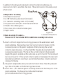
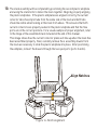
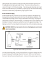
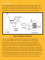
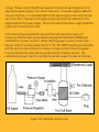
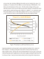
TekStack™ MANUAL AND REFERENCE INFORMATION
≥Introduction
Parker has teamed with TDM Fuel Cell Technologies and the E-TEK division
of PEMEAS Fuel Cell Technologies to produce the TekStak™, line of fuel cell
components, stacks and accessories. This family of rugged, high performance
fuel cell hardware was designed to be easily and repeatedly assembled, operated
and then disassembled. Parker and our partners hope that the TekStak™ product
line serves as a useful educational tool to help train the next generation of
scientists, engineers, technicians and business managers who will be the key
players to implement the Hydrogen Economy of tomorrow.
This manual provides instructions for stack assembly and basic stack testing
procedures, followed by
a brief overview of Proton
Exchange Membrane
(PEM) fuel cells.
Please refer to the
included DVD for
additional assembly and
testing information.
≥ Stack Assembly Procedure
Before beginning assembly, please identify each of the following components.
≥Stack Components
≥ 2 plastic endplates – 1 endplate with pressed-in nuts; 1 without
≥ 1 graphite cathode endplate
≥ 1 graphite anode endplate
≥ graphite bipolar plates, 1 less than the number of cells in stack
≥ membrane electrode assemblies (MEAs), 1 per cell in stack
≥ 8 socket head cap screws, size #10-32
≥ 8 size #10 flat washers
≥ 2 brass slotted screws, size #8-32
≥ 2 size #8-32 hex nuts
≥ 2 nickel-coated brass current collectors
≥ precut PTFE gaskets, 2 per cell in stack
≥ 2 ¼” PrestolokTM, tube fittings
≥ 2 plugs for push-to-connect fittings
≥ 8 Nitrile O-rings, size 2-010
Figure 1: Plastic Endplate
Figure 2: Graphite Cathode Endplate
Figure 3: Graphite Anode Endplate
Figure 4:
Graphite Bipolar Plate
Figure 5:
MEA
Figure 7:
Current Collector
Figure 8:
PTFE Gasket
Figure 9:
Prestolok Fitting
Figure 10: Acetal
Plug
C* Indicates Cathode Side
Figure 6: Bolt,
Washer, and PEM Nut
Figure 11:
O-rings
In addition to the included components listed, the items listed below are
necessary in order to assemble the stack. These items are not included, except
where noted.
Flow Ports
≥Required for Assembly
≥Flat head screw driver
≥4x 1/8” diameter guide dowels (included)
≥¼” diameter assembly stand-off (included)
≥Torque wrench with 5/32” Allen head attachment
≥Powder-free rubber gloves
≥Flat, clean, non-conductive table space
≥Paper towels
Figure 12:
Location of Flow Ports
≥Stack Assembly Procedure –
Please refer to the included DVD for additional assembly instructions
1. Insert 4 of the O-rings into the 4 O-ring grooves on the underside of each
plastic endplate. Next gently press the 2 current collector plates into the
recessed pockets on the plastic endplates. When pressing the current
collector plate into place, it is important that the plate be inserted into the
recessed pocket properly. The tab on the current collector should extend
beyond the plastic endplate on the same side as ports 2 and 3. The tab should
be closest to port 2. If the current collector plate is misaligned, the stack will
leak when assembled, resulting in a potentially hazardous situation and poor
stack performance.
2. One plastic endplate has nuts pressed into the bolt holes. Take this plate and
lay it flat on the table so the Parker logo faces down.
3. Insert the 4 - 1/8”-diameter plastic assembly dowels into the flow ports of the
plastic endplate. The flow ports are the small diameter
ports located within the O-ring grooves.
4. Gently slide the graphite anode endplate over the 1/8” dowels, then lower it so
that it rests on top of the current collector.
5. Slide a white PTFE gasket over the dowels so that it rests on top of the graphite
anode end plate.
6. Carefully slide an MEA over the dowels and on top of the PTFE gasket.
It is
very important that the cathode side of the MEA—marked with a “C” —faces up,
away from the flow field on the anode endplate. Note: As the stack is used, the
“C” written on each MEA may fade. During disassembly, identify and mark the
cathode side of the MEA so as to allow for proper reassembly. To mark the MEA,
use a felt tipped pen.
7. Slide another PTFE gasket on top of the MEA, again using the dowels for positioning.
8. If assembling a 1 cell stack, ignore this step and go to step 10. Otherwise, slide
a graphite bipolar plate over the dowels and on top of the PTFE gasket. Ensure
that the serpentine flow field (the hydrogen flow channels) is facing up and
that the notch in the bipolar plate lines up with the notch in the graphite anode
end plate. Align the parallel flow channels on
the face of the plate so that the flow channels
are perpendicular to the tab on the current
collector plate.
9. Repeat steps 6-9 until there are no additional
MEAs to be added to the stack. After
positioning the final MEA and PTFE gasket,
add the graphite cathode endplate rather
than a bipolar plate. Note: At this point, there
should not be any additional bipolar plates,
PTFE gaskets, or MEAs) Again, use the dowels
to slide the plate into place, ensuring that the
notches are aligned and the serpentine flow
field faces downward.
Figure 13: MEA positioning
10. The stack assembly will be completed by positioning the second plastic endplate
and using the stack bolts to fasten the stack together. Begin by properly aligning
the plastic endplates. If the plastic endplates are aligned correctly, the current
collector tabs should protrude from the same side of the stack and both tabs
should be visible when looking at the stack from above. This ensures that both
current collectors are properly seated in the plastic endplate and that the flow
ports are in the correct positions. For a visual example of proper alignment, refer
to the image of the assembled stack included at the end of this manual.
This image shows how the current collector plates will line up when the stack has
been assembled properly. Next, carefully remove the 4 assembly dowels from
the stack as necessary to slide the plastic endplate into place. After positioning
the endplate, reinsert the dowels through the two open ports (ports 3 and 4).
Align Notches
Figure 14: Notch alignment
11. Insert the 8 socket-head cap screws into the bolt holes and into the pressed-
in nuts on the opposite endplate. Ensure that the graphite plates are still
properly aligned prior to tightening the screws. The socket-head cap screws
should be tightened in an alternating diagonal pattern to a maximum torque of
8 in.-lbs using a torque limiting wrench with a 5/32” Allen head attachment. To
assist in proper tightening of the 8 screws, the ¼” diameter height gauge dowel
can be used. When all the bolts are tightened properly, the height gauge dowel
should fit in between the two plastic endplates with little resistance. If the
height gauge dowel does not fit easily into the space between plastic endplates,
the assembly screws should be loosened.
12. With the bolts tightened to 6-8 in.-lbs of torque, the assembly dowels and
height gauge dowel may be removed. The brass screws may now be passed
through the hole in the current collector tabs
and tightened into place using the brass
#8-32 nuts. These brass screws can
be used to connect electrical leads to
the stack for testing.
13. If push-to-connect fittings
are not integrated into the plastic
endplates, then threaded push-toconnect fittings have been included in
the kit. If applicable, screw the threaded
fittings into the appropriate ports on the
endplate. The fuel inlet fitting should be
screwed into port #4 on the endplate
with the pressed in nuts; the fuel
exhaust fitting should be inserted into
port #3 on the opposite endplate.
Figure 15: Bolt tightening pattern
A.Test Infrastructure
Fuel cell testing requires control of two different but equally important set
of parameters—the reactant flow and the electronic load. Both groups are
addressed briefly below. In all cases, ensure that whatever test infrastructure is
put in place is in compliance with all local safety codes and facility regulations.
Warning: Normal precautions associated with hydrogen must be taken. DO NOT use hydrogen in a sealed or unvented
room. DO NOT use in close proximity to open flame or other
ignition sources. Observe all local safety codes and regulations.
Reactant Flow Control Infrastructure
Fuel Supply Options
Two methods that can be used to control the fuel supply to the stack. They are
known as “dead-ended” and “continuous flow.” Dead-ended flow is based upon
pressure regulation. Continuous flow is based upon flow rate control.
Regardless of the option selected, the fuel source can be a pressurized hydrogen
cylinder, a charged metal hydride cylinder, or a hydrogen generator. “High purity”
grade (99.995% or greater) or better will ensure the catalysts in the MEAs are
not contaminated by impurities in the fuel stream. If a cylinder of compressed
hydrogen gas is not used as the fuel source, it is important that a filter be
inserted into the fuel supply line immediately downstream of the hydrogen source
to prevent contaminants from poisoning the MEAs. This is especially true if
alternative hydrogen storage/supply options, such as a hydride cylinder or sodium
borohydride, are employed.
For both dead-ended and continuous-flow fuel supply options, the maximum fuel
supply pressure is 3 psi. Two-stage regulators can be used to reduce the fuel
pressure to an appropriate level.
The hydrogen source must be connected to the stack and other infrastructure
through appropriate tubing and tube fittings. The stack comes with push-toconnect fittings for ¼” OD flexible tubing. The tubing used should be semi-rigid
and be selected based upon permeability of hydrogen gas. Recommended tubing
materials include PTFE, polyurethane, polypropylene or PVC.
Dead-ended Fuel Supply
If dead-ended fuel flow is selected, precise pressure regulators and gauges will
be required to achieve the necessary control over the fuel delivery pressure. The
recommended operating pressure range is between 0.5 and 2 psig. If hydrogen is
supplied via a cylinder of compressed gas, it is likely that two or more regulators will
be needed to reduce the pressure seen by the stack to the appropriate range. The
hydrogen outlet of the stack should be blocked with one of the included acetal plugs.
CAUTION: DO NOT over pressurize the stack. Hydrogen pressure should never exceed 3 psi.
Figure 16: Dead-ended H2 flow setup
For dead-ended operation, no flow controller/meter is required, though one may
be used to measure the hydrogen flow into the stack. With no current load on
the stack, the fuel flow rate should be zero. A non-zero flow rate at open circuit
indicates leaks within fuel supply line. If the leak rate at open circuit is found to
be greater than approximately 15 mL/min, then steps should be taken to reduce
the leak rate, such as checking that all fittings are sufficiently tight and that the
stack is assembled properly.
In this configuration, humidification of the hydrogen stream is optional. Reactant
humidification helps the stack to attain optimum performance. If the hydrogen
stream is humidified, it is necessary that the fuel line is purged approximately every
30 minutes to prevent water build up on the anode of the cells. Note: Purging the
stack should be done carefully and in a well-ventilated area. If the hydrogen stream
is not humidified, then no purge is required.
Continuous Flow Fuel Supply
If a continuous flow configuration is used, fuel supply will be managed via a flow
controller or a flow meter combined with a valve. The flow meter/controller used
can be a simple rotameter (if a hydrogen calibration scale is available) or a more
sophisticated digital flow controller complete with computer control options. The
required range of the flow meter/controller will vary depending upon the number
of cells in the stack and the maximum current load to be placed on the fuel cell
stack. As a general guideline, the hydrogen flow required (assuming that all
hydrogen reacts with oxygen to form water) is 7.5 ccm/A/cell at room temperature
and standard pressure. Refer to section III for information on how to calculate the
required hydrogen flow rate for a specific test scenario.
In the continuous flow configuration, it is still necessary to regulate the hydrogen
supply pressure such that the stack does not see fuel pressures above 3 psig.
It is necessary that the fuel stream be humidified prior to introduction to the
stack. Ideally, the stream would be saturated prior to introduction to the stack.
If budgetary constraints prevent the use of an appropriately sized humidifier, a
bubbler or diffuser with deionized water may be used to provide a humidified, but
not saturated, hydrogen stream.
Air Supply Options
The air supply method used is dictated by the design of the stack; specifically, it
is dictated by the flow fields on the cathode sides of each graphite plate. If the
plates have several parallel air flow channels, the stack is “air breathing.” If the
flow pattern is serpentine, then the stack requires a pressurized air supply.
Air Breathing
The term “air breathing” is used to indicate that the stack is supplied with
air in a passive manner. That is, there is no requirement for any air supply
infrastructure—the stack will produce power as long as fuel is supplied to it.
However, the user may wish to use a small fan to realize slightly improved cell
performance. If this is the case, a DC fan can be positioned in front of the air flow
channels in the graphite plates. If the stack is large enough that it can supply the
fan with sufficient power, the fan can be powered off of the stack by connecting the
positive lead from the fan to the stack cathode (air electrode) and the negative lead
to the stack anode (hydrogen electrode). Alternatively, a DC power supply set to
the proper voltage can be used to run the fan. Note: If the stack is used to power
the fan, any test data collected should reflect this parasitic load on the stack.
If the stack to be tested requires a forced air supply, the requirements are similar
for pressure and flow control of hydrogen, in that pressure regulator(s) and a
flow controller or a flow meter and an adjustable valve are required. The primary
difference is in the flow rate of air selected. Again, the user should determine the
appropriate air flow rate for the test that he or she wishes to run. In this case,
the general rule is that the oxygen required (assuming that all oxygen reacts with
hydrogen to form water) is 3.75 ccm/A/cell at room temperature and standard
pressure. However, oxygen comprises only about 20% of the air, so the air flow
required, again assuming complete oxygen conversion, is 18.75 ccm/A/cell.
It is also necessary that the air stream be cleaned by a 10 micron filter (or better).
The air should then be passed through a desiccator to dry the air prior to passing
through the flow controller. Downstream from the flow control device, the air
must be humidified to the maximum extent possible, as discussed above in
relation to fuel humidification in continuous flow configuration.
Caution: Prevent electric shock through the use of proper plugs and
wires and good earth ground connections. Ensure that no bare wire is exposed.
Follow all safety instructions provided by the electronic load manufacturer.
In a laboratory setting, fuel cell stacks are commonly tested using DC electronic
loads to control the current load placed on the stack. For ongoing stack testing,
it is advisable to use a DC load because of the precise control and measurement
offered, as well as the ability to communicate with a properly equipped data
acquisition system. The DC load selected must have current, power, and voltage
ranges that are appropriate for the stack or stacks to be tested. Often, the lower
end of the voltage range of a DC electronic load is greater than 0 V; examples of
some common lower voltage limits include 5 V and 1.5 V. If it is necessary to test
the stack while the operating voltage is less than this lower limit, a DC power
supply with an appropriate current range can be put in series with the fuel cell
stack to boost the voltage seen by the DC load. This “extra” voltage can then be
subtracted from the total voltage measured by the load to determine the stack
voltage. Please consult the DC load supplier for selection and integration of an
appropriate power supply, if this step is necessary. If a power supply is added in
series to the stack, it is recommended that the power supply comes after the fuel
cell stack; that is, the stack cathode (positive) lead should be connected to the
negative lead of the power supply. The positive lead of the power supply should be
connected to the electronic load.
If the stack testing requirements are such that a DC electronic load is not
necessary, then the stack can be tested using digital multimeters (DMMs) and
combinations of power resistors. When selecting power resistors, ensure that
they are rated for a proper power level (P = I2R). One DMM should be put in parallel
with the fuel cell stack and used to measure voltage; another should be placed
in series between the stack and the load and used to measure current. The
combination of power resistors can then be varied to adjust the load on the stack.
Figure 18: Simplified system setup
B.Test Preparation/Set-up
As discussed above, there are several ways that reactant streams may be
supplied to the fuel cell stack. Here, the test prep procedure is described for each
of those flow scenarios.
If the hydrogen outlet is to be closed off so that the stack is “dead-ended,” then
hydrogen flow will be controlled by a pressure regulator. Begin by connecting the
hydrogen supply to the stack via pressure regulators. If a flow controller is in the
fuel line, set it to full flow. Turn the pressure regulator(s) down to fully open (no
pressure). Cap off the fuel outlet of the stack with the included plug. Turn on the
hydrogen source--either by opening the pressurized cylinder or by activating the
hydrogen generator. Slowly increase the pressure on the regulator closest to the
hydrogen supply. If only one regulator is used, set the pressure seen by the stack
(i.e. downstream from the regulator and upstream of the stack) to between 0.3
and 2 psi. Record the fuel pressure.
Warning: Hydrogen pressure should never exceed 3 psi. Immediately
turn off hydrogen supply and relieve hydrogen pressure in a WELL VENTILATED
area if a pressure spike occurs.
If a series of regulators is used to supply fuel to the stack at an appropriate
level, then set the pressure in each regulator sequentially, beginning with the
regulator closest to the fuel supply. Make sure that each regulator receives
an input pressure within its operating range. Increase the pressure at each
regulator from 0 very slowly. If the pressure exceeds the recommended range for
a regulator or the stack itself, carefully vent the hydrogen and lower the pressure
setting on the regulator to 0. Turn the hydrogen supply back on and slowly
increase the pressure until it is in the appropriate range. Note: If the fuel supply
is humidified and the stack is dead-ended, then it will be necessary to purge the
fuel side of the stack by opening the fuel outlet and allowing water to be drained.
This should be done approximately every 30 minutes.
Setup for Continuous Flow Testing
Connect the fuel supply to pressure regulators such that the supply pressure is
no more than 2 psi. Install a flow controller or a flow meter and proportional valve
downstream of the last regulator. Close the controller or valve so that there is
no flow. Ensure that the hydrogen outlet is open. Slowly open the controller or
valve to increase the hydrogen flow rate to an appropriate level based upon the
tests to be conducted. Assuming that the hydrogen is Ultra-High Purity (UHP)
or chemically pure, then no filtration is required. Otherwise, be sure to use a 10
micron (or finer) filter to eliminate impurities. Downstream of the flow controller,
the hydrogen should be hydrated as described above.
Air Flow Setup
If the stack is air-breathing, no setup is required. As an option, a small fan can be
connected to a power supply to increase the air flow through the fuel cell stack. If
the stack requires a pressurized air supply, set up the air supply in similar fashion
to how the hydrogen supply is set up for continuous flow testing, using pressure
regulators and a flow controller. If a shop air supply is used, it is important
that the gas be dried and be sure to use a 10 micron (or finer) filter to eliminate
impurities. After the air has passed through the flow controller, it should be
humidified using an appropriately sized humidifier or bubbler.
Electrical Setup
In order to measure the electrical performance of the fuel cell stack, the stack
cathode (air electrode) should be connected to the positive terminal of the
electronic load and the anode should be connected to the negative terminal of
the load. If using a four point measurement system, the positive voltage sense
lead should be connected to the cathode and the negative sense lead should be
connected to the anode. Once fuel flow has been initiated, the load can be turned
on. Ensure that the current load is off (set to 0 A).
C.Common Testing Procedures
There are many ways to test a fuel cell stack depending upon what sort of
information is sought. This section will introduce the break-in procedure
recommended in order to reach maximum performance and the most common
simple tests. Additional tests can be designed by the user in order to provide data
to answer specific questions.
After the stack has been assembled for the first time, it is necessary to
“break-in” the membranes in order to achieve optimal performance. The
point of this process is to hydrate the membranes so as to maximize their ionic
conductivity. This is done by introducing humidified reactant flow to the stack. It
is recommended that the fuel flow be dead-ended. Remember to occasionally
purge at the fuel outlet to drain excess water. Once an Open-Circuit Voltage (OCV)
of approximately 0.9 – 1 V/cell is observed, slowly begin increasing the current
load on the stack from 0 A up to a maximum of 1 A in steps of 0.1 A. Increment
the load once voltage has stabilized from the previous increase. Since the
goal is to fully hydrate the membranes, this will be achieved most quickly by
pulling the maximum current load that is safe for the stack. A safe level is best
determined by the average cell voltage. For brief periods (less than 2 minutes),
it is acceptable for the stack to operate with an average cell voltage of 0.4 V/cell.
For longer periods of time, a safe minimum average cell voltage is 0.55 V/cell
during break-in. Once the stack voltage has stabilized at this level, maintain the
current load for a period of two to eight hours. The time required to break-in
the stack is dependent upon how high the current load is. One convenient way to
determine if break-in is complete is to check the stack voltage every few hours at
a specific current level, such as 1 A or 1.5 A. If the stack voltage has not changed
substantially from the previously measured operating voltage, the break-in
process may be considered complete.
It is strongly recommended that the stack be monitored during the break-in
period. However, if the stack is to be left unattended, then fuel humidification will
need to be discontinued to prevent the anode flow channels from flooding while
the stack is unattended. Alternatively, the stack could be run within a continuous
flow configuration and humidification may be continued.
After break-in is complete, actual testing may begin. The most common test
for a fuel cell or a fuel cell stack is the polarization curve. Polarization curves
are also known as V-I or V-j curves as they are plots of the stack voltage against
the current load (I) or current density (j). A second common plot that typically
accompanies the V-j curve is the power density curve, which plots power density
(the product of stack voltage and current density) against current density. One
method for collecting V-j and power density curves is briefly introduced here; for
additional information, the reader is encouraged to refer to the multitude of peerreviewed journals and reference texts such as Fuel Cell Systems Explained and
The Fuel Cell Handbook.
1.Begin flowing humidified fuel to the stack using either dead-ended or
continuous-flow methods as previously described. If desired, use a small
fan to actively supply air to the stack. The stack temperature should also be
monitored using a thermocouple.
2.Turn on the electronic load and set the current load to 0 A (open circuit). Allow
the stack voltage to stabilize and record this voltage. This is the OCV. If the
stack is being operated dead-ended, note the hydrogen flow with no load.
Under these conditions, if a fuel flow is indicated by the meter/controller, it is
most likely due to a hydrogen leak within the system.
3.Increase the current load on the stack to 0.1 A and allow the stack voltage to
stabilize. Record the stack voltage and the fuel flow rate. The stack voltage
should take about a minute to reach a stable level.
4.Continue to increase the stack current in small increments until the power
output of the stack has begun to decrease as current increases or the stack
voltage does not stabilize at a particular current load.
5.Using the same current increment, decrease the current load on the stack and
record stack voltage as it stabilizes. This will allow for the quantification of any
hysteresis effects.
6.Having done a complete current sweep, beginning and ending at 0 A, now
the data must be plotted. To calculate the current density, simply take the
0.100
4.00
0.080
3.00
0.060
2.00
0.040
1.00
0.020
0.00
0.00
(W/cm 2)
5.00
Cell Power Density
Stack Potential (V)
active area of an individual MEA and divide the current load by this value. For
example, a 1 A load on a 10 cm2 MEA is a current density of 100 mA/cm2. Plot
these current densities on the x-axis. Plot the stack voltage on the y-axis.
Take the product of the current density and stack voltage to calculate the stack
power density, which will have units of W/cm2 or mW/cm2. It is common to plot
the power density curve on the same graph as the V-j curve, using a second
y-axis so that the stack current and power density are properly scaled.
0.000
0.02
0.04
0.06
0.08
0.10
0.12
0.14
0.16
0.18
0.20
2
Current Density (A/cm )
Forced Air Supply - V
Passive Air Supply - V
Forced Air Supply - Power
Passive Air Supply - Power
Figure 19: Example V-j and Power Density curves
Several parameters can be varied to yield a significant number of V-j curves for
basic analysis—including running the stack with continuous fuel flow versus
dead-ended fuel flow, running the stack with humidified versus dry fuel, testing the
stack with a passive air supply versus a forced air supply, varying the fuel flow rate
(continuous flow) or fuel pressure (dead-ended), and varying stack temperature.
A.Testing Precautions
To ensure the safety of the testers and the product, precautions must be taken
when testing a fuel cell stack. With regard to the test system, this includes
ensuring that the hydrogen gas is properly vented from the area.
To avoid damaging the stack during testing, there are several other precautions
that should be taken. The first is to avoid operating the stack at very low voltage.
Do not ever short circuit the fuel cell stack. Do not allow the stack operate at
level such that the average operating voltage of the individual cells is less than
0.2 V for a hydrogen fueled stack. A second precaution that should be taken
to ensure proper stack operation is to introduce only humidified (preferably
saturated) gases to the stack. If localized dry out of the MEA occurs, small holes
could develop in the membrane material due to local hot spots. These holes
would allow hydrogen and air to mix, resulting in a dangerous situation.
Caution: Confirm that MEAs are in good condition prior to exposure to
hydrogen. Conduct a leak check to prevent mixing of hydrogen and ambient air.
III.P roton Exchange Membrane Fuel Cells Reference Information
This section seeks to provide a general introduction to basic concepts related to
basic operation of fuel cells and how to quantify the performance of a fuel cell.
For more detailed information, please refer to more in-depth fuel cell references,
such as Fuel Cell Systems Explained and The Fuel Cell Handbook.
On a fundamental level, a PEM fuel cell is a device that converts hydrogen and
oxygen into water and electricity. As shown in the schematic below, hydrogen
molecules flow to the anode of the MEA. Here, they are split into electrons and
positive ions. The positive ions migrate through the membrane material; the
electrons cannot pass through the membrane, so they are forced to pass through
the load (e.g. a light bulb) before the electrons reach the cathode of the MEA. At
the cathode, the electrons combine with the positive ions (positive hydrogen ions
or protons) that have passed through the membrane and oxygen molecules from
the air to form water. This completes the electrical circuit, resulting in electrical
power from the stack.
A fuel cell’s performance is primarily defined by the amount of fuel and air
required to produce a certain amount of power. More specifically, the amount of
reactants necessary to yield a specific cell or stack voltage at a specific current
density defines a fuel cell’s performance.
The voltage at which a fuel cell functions is known as the operating voltage. The
operating voltage can range from 0 V up to a theoretical maximum known as the
Nernst Potential. The Nernst Potential is, in essence, the electrical potential
difference (voltage) that would result from a given chemical reaction, such as the
combination of hydrogen and oxygen, at very specific conditions. In the case of
the formation of water from hydrogen and oxygen at standard temperature and
pressure, the Nernst Potential is approximately 1.2 V. The voltage efficiency of
a single cell can therefore be calculated by dividing the operating voltage by this
voltage. For an multi-cell stack, voltage efficiency is calculated by taking the
stack voltage and dividing it by the Nernst Potential multiplied by the number of
cells in the stack.
Similarly, the current load on a stack is also an important parameter used
to measure the performance of a fuel cell. The maximum current, or ideal
current, is dictated by the amount of fuel and air supply. The ideal current can
be calculated using Faraday’s current law, which states that the ideal current is
proportional to the reactant flow rate multiplied by the number of electrons being
transferred in the reaction. Detailed calculations will not be carried out here, but
using Faraday’s current law, it can be shown that a 1 A current is equivalent to
7.5 mL/min H2 at room temperature and standard pressure.
Based on the total current produced by the stack and fuel flow going into the
stack, the fuel utilization can be calculated. Fuel utilization is defined as the ratio
of actual current produced to the ideal current that could be produced from a
given fuel flow rate. For instance, if the fuel flow rate is set at 15 mL/min and the
current load produced by the stack is 1.5 A, the fuel utilization is 75%
(1.5 A actual current / 2 A ideal current).
The inverse of utilization is, mathematically, the ratio of ideal current to actual
current; this is referred to as NOS or “stoics.” Air/oxygen supply is commonly
considered in terms of stoics, which effectively describe the excess reactant
supplied. For example, if the air is supplied at 2 stoics, this means that there
is exactly twice as much oxygen flowing into the stack as is required for a given
current load. For air breathing stacks, the number of stoics is not reported.
IV.C ustomer Support
Contact your authorized Parker Distributor, or if you purchased the product direct
from Parker, contact us at:
Parker Energy Systems
Parker Hannifin Corporation
95 Edgewood Avenue
New Britain, CT 06051-4100
Tel: 1-877-217-4501
Fax: 1-866-781-7426
[email protected]
V. Introduction to Parker Energy Systems and Parker Hannifin Corporation
About Parker Hannifin
Headquartered in Cleveland, Ohio with over 200 locations in 45 countries, Parker
Hannifin Corporation is a world-leading manufacturer of engineered components
and systems for a wide range of fluid control applications. Parker appreciates the
far-reaching benefits of a hydrogen-based economy and is well positioned to help
the fuel cell industry along the challenging road towards commercialization.
About Parker Energy Systems
Parker’s involvement with fuel cell technology is a natural outgrowth of its existing
product technologies and engineering capabilities. Parker already manufactures
most of the individual fittings, valves, hoses, seals and filters required to meet
balance of plant needs for mobile and stationary fuel cell power plants. However,
to achieve the kind of dramatic cost reductions required for the commercialization
of fuel cell products, Parker created its Energy Systems Business Unit to combine
components with high efficiency motors, pumps, compressors and programmable
electronic controls to deliver complete system solutions. Through Parker Energy
Systems (PES), Parker offers humidifiers, fuel cell stack assemblies, cathode air
compressors, hydrogen circulators, flexible stainless steel tubing, filtration products,
control valves, liquid pumps, pressure regulators & transducers, positioning tables,
PEM fuel cell stack components, seals, manifolds, fittings and tubing.
Parker’s recent collaboration with Vectrix Corporation to design and build a
prototype Fuel Cell/Electric Hybrid Motorbike is an example of PES’s system
integration capabilities. Under PES’s guidance, ten Parker divisions provided
product and engineering assistance to a start-up company (Vectrix) launching the
world’s first hybrid fuel cell/electric scooter. The scooters will be sold in Europe
where high priced gasoline, lack of parking space and even government taxes and
outright bans on internal combustion engines in some cities should make them
very popular. Additionally, PES is working with fuel cell manufacturers producing
power units for public transportation, utility companies and residential systems.
Parker believes that it’s incumbent on manufacturers to think ahead, to provide
for the future of more than just our industries. Oil won’t last forever. Solar, wind
and fuel cell technologies, in addition to being environmentally friendlier right
now, should be developed against the day when they will be urgently needed to
provide the power many take for granted.
To be ready for this day, tomorrow’s engineers and scientists must begin working
with these technologies now. The TekStak product line is intended to provide
students from high school through university-level with the ability to assemble
and test customizable fuel cell stacks. To enhance the educational opportunity
for students, the TekStak product line includes a range of balance of plant
components that can be combined with the fuel cell stacks, allowing students to
construct their own complete fuel cell system.
≥Parker Energy Systems
is preparing the world. Today.
VII.Recommended Reading
The following is a brief list of recommended sources for additional information
relating to fuel cells and fuel cell systems.
Books
Fuel Cell Systems Explained, Second Edition by James Larminie and Andrew
Dicks, John Wiley & Sons, Ltd. 2003
Fuel Cell Handbook (Seventh Edition) by EG&G Technical Services, Inc. for the
National Energy Technology Lab (NETL). 2004 Available online at
http://www.netl.doe.gov/seca/pubs/FCHandbook7.pdf
Websites
www.parker.com/fuelcells - Homepage of Parker Energy Systems
www.fuelcells.org - Contains a wide variety of information relating to fuel cells
www.nrel.gov - Homepage of the National Renewable Energy Lab (DOE)
www.netl.doe.gov - Homepage of the National Energy Technology Lab (DOE)
www.usfcc.com - Homepage of the US Fuel Cell Council (USFCC)
For more information, please visit: parker.com/fuelcells
FC0616
May 2006