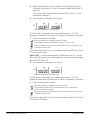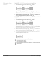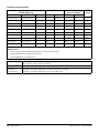
1
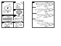
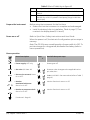
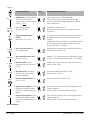
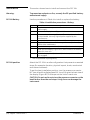
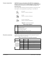
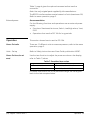
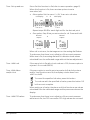
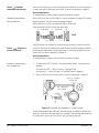
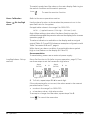
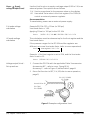
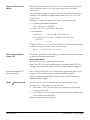
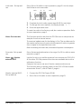
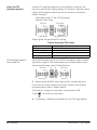
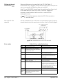
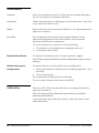
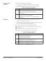
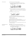
GE
Measurement & Control
Druck DPI 104
Digital Pressure Indicator
User manual - K0394
© 2011 General Electric Company. All Rights Reserved. Specifications are subject to change without notice. GE is a
registered trademark of General Electric Company. Other company or product names mentioned in this document
may be trademarks or registered trademarks of their respective companies, which are not affiliated with GE.
A1.1
A1.2
Customer service
B2
Visit our web site: www.ge-mcs.com
1
(a)
A2
A1.3
2
3
5
7
(b)
8
6
4
9
10
Vo
A2
A3
13
(c)
(A)
12
14
11
(B)
16
(E)
15
(C)
(D)
(F)
B1
(d)
K0394 Issue 3
Table of Contents
Table of Contents .......................................... 1
Introduction ................................................... 2
Safety .............................................................. 2
Marks and symbols ............................................. 2
To Start ........................................................... 3
Key to figure A1 (Instrument) .......................... 3
Key to figure A2 (Display) .................................. 4
Key to figure A3 (Accessories) ......................... 4
Prepare the instrument ..................................... 5
Power on or off ...................................................... 5
Menu operation ..................................................... 5
Installation ..................................................... 7
DPI 104 battery ...................................................... 7
DPI 104 position .................................................... 7
Pressure connections ......................................... 8
Electrical connections ........................................ 8
External power ...................................................... 9
Operation ....................................................... 9
Menu: Set units ...................................................... 9
Menu: Set tare (or set zero) .............................. 9
Menu: Monitor maximum/minimum ........ 11
Menu: Monitor a pressure switch .............. 11
Menu: Calibration .............................................. 12
Menu: Set low/high alarm ............................. 12
Menu: Supply voltage output (Vout) ......... 13
Menu: Set Vout scale factor ......................... 14
Menu: Set automatic power OFF ............... 14
Menu: Set lock code ......................................... 14
Menu: Set scan rate ......................................... 15
Menu: Monitor external IDOS ....................... 15
Menu: Set FSO low/high registers .............. 16
Software/network connections ................. 17
Error indications ................................................. 17
[EN] English - K0394 Issue 3
Maintenance ............................................... 18
Replace the batteries ....................................... 18
Restore the original configuration ............. 18
Calibration .................................................. 18
Equipment and conditions ............................ 19
Procedures ............................................................ 19
Specification ............................................... 23
General ................................................................... 23
Environmental conditions................................23
Electrical ................................................................. 23
Additional data......................................................23
Pressure measurement .................................. 24
Table of Contents 1
Introduction
The Druck DPI 104 is a digital pressure indicator that measures the
pressure of liquid, gas or vapor and shows the pressure value on a
liquid crystal display (LCD). It also has the Intelligent Digital Output
Sensor (IDOS) technology to use data from a Universal Pressure
Module (UPM).
The DPI 104 includes the functions that follow:
Function
* Measure pressure - Accuracy: 0.05% full scale (FS)
Large 5-digit main display with 11 pressure units
Adjustable Full Scale Output (FSO)
20 segment analog dial in increments of 5% FSO
(large division marks = 10% increments).
2.5 digit percentage indicator (0-100% FSO)
8-pin connector port: For RS232, **IDOS UPM, external power supply
Alarm output for high/low pressure conditions
Switch input to monitor an external pressure switch
Analogue voltage output (Vout/Vo): 0.05 to 5 Vdc
Other functions: maximum/minimum, tare, Vout scale factor, automatic
power off
* Refer to —enu operations.
** Optional item
Safety
Other marks and
symbols
Before using the DPI 104, read and understand all the related data.
This includes: all local safety procedures, Safety instructions and
User Guide and this publication.
Complies with European Union directives
Warning - refer to the manual
Do not dispose of this product as household waste. Refer to
Maintenance.
2
Introduction/Safety
K0394 Issue 3 - [EN] English
To Start
Key to figure A1
(Instrument)
Table 1: Key to figure A1
Item
1.
2. •
•
•
•
3.
5. •
•
•
10.
[EN] English - K0394 Issue 3
Menu mode: Press and hold to show the first menu option. To
move down the menu structure, press repeatedly, or continue to
press and hold.
Reject or stop the change to a value.
In maximum/minimum mode. Press to show the maximum and
minimum values since the last reset.
= maximum
= minimum
In menu mode:
- On/OFF selection
- Increase/decrease a value
4.
6.
7.
8.
9.
Description
8-pin connector for external power supplies, RS232/UPM
connections and signal input/output.
Power on button.
- Move the decimal left/right
Pressure sensor and connector with 320° of turn: gauge (g),
absolute (a) or sealed gauge (sg). Refer to menu operations, page 5.
In menu mode:
- Accepts a menu selection
- Accepts a value
- Shows the next menu level
In Tare mode: Set the pressure value on the display to zero.
In maximum/minimum mode. Reset the maximum/minimum
values.
Display bezel with 348° of turn.
O-ring.
Battery connector.
Battery: 9 V Alkaline (supplied but not installed). Refer to menu
operations, page 5.
Battery clamp with two screws.
To Start 3
Key to figure A2
(Display)
Table 2: Key to figure A2
Item
11.
12.
13.
Description
5-digit main display.
2.5-digit percentage indicator (0-100% FSO).
%FSO = [applied pressure/(FSOHigh—FSOLow)] * 100
20 segment analog dial in increments of 5% FSO (large division
marks = 10% increments).
%FSO = [applied pressure/(FSOHigh—FSOLow)] * 100
14.
The units of measurement: kPa, MPa, kg/cm2, psi, mbar, bar,
mmHg, mmH2O, mH2O, inH2O, inHg.
15.
Mode indication.
Voltage output (Vout) mode - On.
RS232 connection. The data transmit/receive function is active.
Switch mode - On. To monitor an external pressure switch.
= switch closed
= switch open
Menu Lock mode - On. To restrict access to the menu functions.
Alarm mode - On. The symbol flashes when the measured value
satisfies one of the alarm conditions.
= High alarm
= Low alarm
Maximum/minimum mode - On.
IDOS UPM mode - On. To monitor pressure from a UPM
16.
Key to figure A3
(Accessories)
4 To Start
Low battery power indication: Battery life ≤ 15%.
Table 3: (Part of Table) Key to figure A3
Option Description
(A)
Part No. IA4090-1-V0: DPI 104 to PC RS232 cable (8-pin to 9-pin
D-type connector). To transmit data to a PC for applicable
monitor and control software (accessory D).
(B)
Part No. IA4101-1-V0: DPI 104 to UPM cable assembly. The
assembly has these connections:
UPM cable + 5-pin connector: To give an IDOS UPM a 3 V power
supply and an RS232 connection to the DPI 104 - Figure B2 (d).
GND: Ground connection.
V-OUT: To supply a voltage output (Vo) - Figure B2 (c).
ALARM: To supply an alarm output - Figure B2 (b).
SWITCH: To monitor an external switch - Figure B2 (a).
12V: 12V input for accessory C - Figure B2.
Note: The assembly can supply 12 V to the DPI 104 and 3 V to the
IDOS UPM.
(C)
Part No. 191-129: Universal 12V power supply for accessory B.
(D)
Part No. 1S-SICALPRO-DPI104: SiCal PRO monitor and control
software. This includes accessory A.
Note: Intecal calibration software is also available. To download a
copy, visit: www.ge-mcs.com
K0394 Issue 3 - [EN] English
Table 3: (Part of Table) Key to figure A3
Option Description
(E)
Part No. 1S-04-0027: 8-pin connector for A1: item 1. Refer to
Table 6.
(F)
Part No. 182-190: DPI 104 high pressure adaptor (9/16 UNF to
3/8 BSP) for a PV212 hydraulic hand pump [range ≥ 1000 bar
(15000 psi)].
Prepare the instrument
Power on or off
Before using the instrument for the first time:
•
Make sure that the instrument is complete and undamaged.
•
Install the battery (refer to installation, Table 4: page 7). Then
re-attach the display bezel [A1: item 6].
Refer to Quick Start, Safety Instructions and User Guide.
When the power is off, the last set of configuration options stays in
memory.
Note: The DPI 104 uses a small quantity of power while it is OFF. To
put into storage for a long period, disconnect the battery (refer to
menu operations).
Menu operation
Menu Description
Steps
1
2
OFF
= Power supply: OFF only.
unitS
= Set units: (A2: item 14).
Pressure value changes to the applicable units:
psi, mbar, bar ...
t On
= Set tare (or set zero): Set to
On or OFF.
On ➤ tA 00.000 : Set a tare value (refer to Table 7,
page 9).
= Monitor
maximum/minimum:
Set to On or OFF.
Monitor function is set on or off.
= Monitor a pressure switch:
Set to On or OFF.
Monitor function is set on or off.
OFF
OFF
-
Result/Subsequent steps
Power goes off.
(Continued - Page 6).
[EN] English - K0394 Issue 3
To Start 5
Page 5
Menu Description
Steps
1
2
Result/Subsequent steps
C _ _ _ _ = Calibration: To continue, set
the correct calibration
access code = last four digits
of S/N. *******
C0 (correct the zero offset value) ➤
C2 (do a two-point pressure calibration) ➤
V2 (do a two-point voltage calibration), refer to
menu operations.
= Set low/high alarm:
Set to On or OFF.
On ➤ 000.0 ↓ ➤ 100.0 ↑
Set a value for the low and/or high alarm (0 to
105% FSO).
= Supply voltage output
(Vout):
Set to OFF, P-V, or US.
P-V: Vout is proportional to the pressure value on
the display. Make sure the Vout scale factor is
correct.
US ➤ 000.0: Set a Vout value (0 to 100%) to control
an external pressure regulator. Make sure the
Vout scale factor is correct.
S 1.00
= Set Vout scale factor: A
Vout adjustment.
If applicable, set a new Vout scale factor (0.01 to
9.99), factory value = 1.00.
Au On
= Set automatic power OFF:
Set to On or OFF.
On ➤ Au 15 : Set the period for automatic power
OFF (1 to 99 minutes), factory value = 15 minutes.
L OFF
= Set lock code: A menu
protection facility. Set to On
or OFF.
On ➤ L 000 : Set a new lock code (if necessary),
factory code = 000.
Sc 02
= Set scan rate: A rate that
the DPI 104 uses to take
pressure samples.
Set an applicable rate (02 to 10 Hz),
factory value = 02 Hz.
OFF
= Monitor external IDOS: Set
to On or OFF.
Monitor function is set on or off.
FS ↓
= Set FSO low register: To set
a different range for these
functions: analog display, %,
alarm.
Set a value for the low end of the range (refer to
Table 8, page 16).
Factory value = Factory calibration value.
FS ↑
= Set FSO high register: To set
a different range for these
functions: analog display, %,
alarm.
Set a value for the high end of the range (refer to
Table 8, page 16).
Factory value = Factory calibration value.
A OFF
OFF
Normal display
6 To Start
K0394 Issue 3 - [EN] English
Installation
This section shows how to install and connect the DPI 104.
Warning:
To prevent an explosion or fire, use only the GE specified battery
and external supply.
DPI 104 Battery
Use the procedures in Table 4 to install or replace the battery.
Table 4: Installation procedures - Battery
Step
1
2
3
4
5
6
7
8
Procedure
If applicable, set the power to off and isolate the external
power supply.
Remove the display bezel (Figure A1.2).
Make sure that the o-ring [A1: item 7] and the related surfaces
are serviceable. Use only original parts supplied by the
manufacturer.
Remove the battery clamp [A1: item 10].
If applicable, disconnect the battery connector [A1: item 8] and
*discard the used battery.
Attach the battery connector [A1: item 8] to the new battery.
Install the new battery (Figure A1.3) and re-attach the battery
clamp [A1: item 10].
Push the display bezel [A1: item 6] back into position until it is
fully engaged.
* Use an applicable recycling facility.
DPI 104 position
Attach the DPI 104 in a safe configuration that prevents unwanted
stress (for example vibration, physical impact, shock, mechanical
and thermal stresses).
To get the best installation position, turn the pressure connector
(A1: item 4) and the display bezel (A1: item 6) to give the best view of
the display (Figure B1). End stops set the limits in each axis.
CAUTION: Do not use force to turn the pressure connector or the
bezel farther than the end stops. Using force can damage the
instrument.
[EN] English - K0394 Issue 3
Installation 7
Pressure connections
CAUTION: Do not use the body of the DPI 104 to tighten the
pressure connection, this can cause damage. Use the flat faces
on the pressure connector to hold the body and tighten the
pressure union.
Use an applicable method to seal the pressure connections, and
then tighten to the applicable torque (Figure 1 and Table 5).
1
a) 1/4 NPT:
Pressure < 1000 bar (15000 psi)
2
1
b) G1/4:
Pressure < 1000 bar (15000 psi)
3
1
c) 9/16 x 18 UNF cone:
Pressure ≥ 1000 bar (15000 psi)
Figure 1: Connection methods
Table 5: Key to figure 1
Item
1.
2.
3.
Electrical connections
Description
Applicable DPI 104 pressure connector.
Maximum torque:
1/4 NPT: 68 Nm (50 lbf.ft)
G1/4: 20 Nm (15 lbf.ft)
9/16 x 18 UNF cone: 34 Nm (25 lbf.ft).
(1/4 NPT only) Thread with an applicable sealant.
(G1/4 only) Applicable bonded seal.
The DPI 104 includes an 8-pin electrical connector (A1: item 1).
Table 6 shows the pin connections.
Table 6: Connections for the 8-Pin connector
Connector
Pin
1.
2.
3.
4.
5.
6.
7.
8.
8 Installation
Input/
Output
Input
Input
Output
Input
Output
Output
Input
Output
Description
12-24 Vdc power supply (+)
Signal ground (GND)
RS232 transmit (Tx)
RS232 receive (Rx)
Voltage output (Vo)
Alarm output
Pressure switch input
No connection
K0394 Issue 3 - [EN] English
Table 3, page 4 gives the optional accessories that use the
connector.
Note: Use only original parts supplied by the manufacturer.
The RS232 interface makes a serial network of units (maximum: 99).
Refer to menu operation, page 5.
External power
Recommendation
For the following functions and operations use an external power
supply :
•
Functions: Maximum/minimum, Switch, Low/high alarm, Vout,
IDOS
•
Operations that use the DPI 104 for long periods.
Operation
This section shows how to use the DPI 104.
Menu: Set units
There are 11 different units to measure pressure, refer to the menu
operation, page 5.
Units - Set-up
Refer to Safety Instructions and User Guide, publication K0387.
Menu: Set tare (or set
zero)
Use the tare function to adjust the pressure value on the display,
refer to Table 7, below.
Table 7: Permitted tare values
Range
g: 0.7 bar (10 psi)
a, sg, g: ≥ 2 bar (30 psi)
Permitted tare values
-0.7 bar (-10 psi) to 105% FS
-1 bar (-15 psi) to 105% FS
If a value is set that is not in the permitted range, the value goes
back to the last accepted value.
[EN] English - K0394 Issue 3
Operation 9
Tare - Set-up and use
Menu: Set this function to On (refer to menu operation, page 5).
When this function is On, there are two options to set a
tare value (tA):
•
Menu option: Set the menu “t On”, then set a tA value:
1 2
tA display
tA display
0 to 9, or -
0 to 9
Repeat steps 1 & 2 for each digit and for the decimal point.
•
Zero option: Step 1 lets you set a value for tA. Press and hold.
Normal
output
Normal
output
1
donE
tA = 0
tA = 70 mbar
When tA is not zero, the last segment on the analog dial flashes.
To make sure that there is an indication of the correct pressure:
While tare is On, the analog dial and % indication show values
calculated from the calibrated range without the tare adjustment.
Tare - With Lock
If the menu lock is On with a lock code set < 500, the zero option is
rejected - Error code (E0002).
Tare - With Alarm
and/or Vout
If the zero option is used to set a tare value (tA) while the alarm
and/or Vout functions are On, the display counts down from:
tArE9 to tArE0.
To cancel the specified tA value, press this button.
To continue with the specified tA value, press this button OR
let the count complete.
When setting a tA value, the alarm and Vout functions use values
calculated from the calibrated range and the pressure value on the
display.
Tare - With FSO values
10 Operation
To make sure that there is an indication of the correct pressure
while tare is On, the FSO Low and/or FSO High values are not used.
K0394 Issue 3 - [EN] English
Menu: Monitor
maximum/minimum
Use this function to monitor the maximum and minimum pressure.
It uses the specified scan rate (refer to menu operation, page 5).
Recommendation
To save battery power use an external power supply.
Maximum/minimum Set-up and use
Menu: Set function to On (refer to menu operation, page 5).To save
battery power use an external power supply.
When function is On, use steps 1 & 2 to show the
maximum/minimum since the last reset.
1
maximum
2
minimum
3
donE
Reset
Step 3 resets the values for maximum/minimum, press and hold.
Menu:
Monitor a
pressure switch
Use this function to measure the performance of a pressure switch
(mechanical operation and hysteresis). It uses the specified scan
rate (refer to menu operation, page 5).
Recommendation
To save battery power use an external power supply.
Pressure switch input Set-up and use
1. Connect the DPI 104 with the applicable Table 3 accessories,
page 4:
Accessories B/C - refer to cover, Figure B2 (a).
Accessory E - refer to Figure 2, below/Table 6, page 8.
2. Menu: Set function to On (refer to menu operation, page 5).
Pin 1 (+), 2 (GND)
12-24 Vdc
Pin 7 (Switch)
Pin 2 (GND)
Figure 2: Example configuration - Switch input
These examples (Figure B2 (a)/, above) show the display when the
switch condition changes (open or closed). The analog dial and the
% indication continue to monitor the normal pressure.
[EN] English - K0394 Issue 3
Operation 11
The switch symbol and the value on the main display flash to give
the switch condition and the switch pressure.
Press
To reset the monitor function.
Menu: Calibration
Refer to the menu operations section.
Menu:
alarm
Use the alarm function to show when the pressure is not in the
specified limits for the system.
Set low/high
Set applicable values in the range 0 to 105% FSO:
%FSO = [ Applied Pressure / (FSO High — FSO Low) ] x 100
Note: When setting a tare value, the alarm function uses the
calibrated range and the pressure value on the display (refer to menu
operation, page 5).
The alarm indication is available on the display and as a signal
output (Table 6). Figure B2 (b) shows an example configuration with
Table 3 accessories B and C, page 4.
While there is an alarm condition, the applicable alarm symbol
(high or low) flashes on the display (A2: item 15).
Recommendation
To save battery power use an external power supply.
Low/high alarm - Set-up
and use
Menu: Set function to On (refer to menu operation, page 5). Then
use these steps to set the low and/or high alarm.
Alarm
(% FSO)
Digit = 0 or 1
1
2
Alarm
(% FSO)
3
4
Digit = 0 to 9
5. To finish, repeat steps 3 & 4 for each digit.
If the value entered is not correct, the value resets to the nearest
permitted value. That is:
•
a value in the range 0 to 105% FSO
•
a low alarm value < high alarm value
To accept or change the new value, repeat steps 1 to 5.
Press
12 Operation
To cancel the new value.
K0394 Issue 3 - [EN] English
Menu:
Supply
voltage output (Vout)
Use the Vout function to supply a voltage output (0.05 to 5 V) to an
external system. Two options are as follows:
P-V: Vout is proportional to the pressure value on the display.
US: User mode. Set a value in the Vout register (0 to 100%) to
control an external pressure regulator.
Recommendation
To save battery power use an external power supply.
P-V mode voltage
calculation
Example DPI 104: FSO = 20 bar (or 300 psi),
Vout scale factor = 1.00.
Applying 10 bar (or 150 psi) to this DPI 104:
Vout =
US mode voltage
calculation
( 10/20 * 5V ) / 1.0 OR ( 150/300 * 5V) / 1.0 = 2.5 V
This calculation uses the values set up for the Vout register and the
Vout scale factor.
If the pressure ranges for the DPI 104 and the regulator are
different, set a new Vout scale factor (refer to menu operations).
Vout =
( Vout register / 100 ) * 5V
Vout scale factor
Example - If the Vout register is set to 25%, and the Vout scale
factor is set to 0.5:
Vout = ( 25/100 * 5V ) / 0.5 = 2.5 V
Voltage output (Vout) Set up and use
1. Connect the DPI 104 with the applicable Table 3 accessories:
Accessories B/C - refer to cover, Figure B2 (c).
Accessory E - refer to Figure 3, below/Table 6, page 8.
2. Menu: Set function to OFF, P-V, US (refer to menu operation,
page 5).
Pin 1 (+), 2 (GND)
12-24 Vdc
Vout: 0.05 to 5V
Pin 5 (Vo)
Pin 2 (GND)
Figure 3: Example configuration: Vout
[EN] English - K0394 Issue 3
Operation 13
Menu: Set Vout scale
factor
When the Vout function is set to P-V or US mode, the Vout scale
factor becomes part of the Vout calculation (refer to menu
operations).
If the pressure ranges for the DPI 104 and the external pressure
regulator are different, an applicable scale factor (0.01 to 9.99)
must be set.
Example - To get a 25 bar (or a 375 psi) line pressure with:
•
an External pressure regulator:
FSO = 100 bar (or 1500 psi)
•
a DPI 104: FSO = 200 bar (or 3000 psi)
In this example:
Scale factor
= 100/200 OR 1500/3000 = 0.5
Vout register (%)
= (25/200) x 100 OR (375/3000) x 100
(DPI 104)
= 12.5%
To get a 25 bar (or a 375 psi) line pressure, the DPI 104 uses these
values to supply the Vout value shown below:
Vout =
Menu: Set automatic
power OFF
( 12.5/100 * 5V ) / 0.5 = 1.25 V
The power goes off in a specified period after the last button press
or external software operation.
Recommendation
Use this function for maximum battery life.
Note: The DPI 104 uses a small quantity of power when OFF. For
storage, disconnect the battery (refer to menu operation, page 5).
Automatic power OFF Set-up and use
Menu: Set this function to On. Then set an applicable value in the
range 1 to 99 minutes, refer to menu operation, page 5.
Note: If continuous operation is required, set to OFF and use an
external power supply.
Menu:
Set lock code
Use the lock function to prevent accidental changes to the
configuration. Two options are as follows:
•
Lock code < 500: This locks the menu and the tare function.
Factory code = 000
•
Lock code > 499: This locks the menu but the zero option to set
a tare value is still available.
Refer to menu operation, page 5.
14 Operation
K0394 Issue 3 - [EN] English
Lock code - Set-up and
use
Menu: Set to On (refer to menu operation, page 5). Use the steps
that follow to set a new code.
Lock
Digit = 0 or 9
1
2
Lock
Digit = 0 to 9
3. Complete the lock code, repeat steps 1 & 2 for each digit.
4. To change the menu options, the display shows: L - - 5. Enter the applicable code.
To reset the code to the factory code, do a restore operation. Refer
to menu operations, page 5.
Menu: Set scan rate
This function sets the rate that the DPI 104 uses to take pressure
samples from the internal sensor.
The nominal update rate for the display is 2 Hz. The up-date rate for
the maximum/minimum function and the switch function is greater
than or equal to the specified scan rate.
Note: Increasing the scan rate, increases the power consumption.
Scan rate - Set-up and
use
Menu: Set an applicable value in the range 2 to 10 Hz, refer to menu
operation, page 5.
Menu:
Monitor
external IDOS
Use this function to read the pressure from an external IDOS UPM.
All the other DPI 104 pressure functions are available but not the
calibration function.
Example: Set tare (or set zero), Monitor maximum/minimum.
This function does not supply power to the IDOS UPM and needs
accessories B and C, refer to Table 3, page 4.
Monitor external IDOS Set-up and use
[EN] English - K0394 Issue 3
1. Connect the DPI 104 (Figure B2 (d)).
2. Menu: Set to On (refer to menu operation, page 5).
Operation 15
Menu: Set FSO
low/high registers
Use the FSO low/high registers to set a different range for the
functions that follow: analog display, % indication, low/high alarm.
Initially, these register values are set to the factory calibration
values. Example:
Calibrated range: 0.7 bar (10 psi) gauge.
Selected units: mbar
FSO low
FSO high
0 bar (0 psi)
700 mbar (10 psi)
Table 8 gives the permitted FSO values.
Table 8: Permitted FSO values
Range
All ranges: a, sg
g: 0.7 bar (10 psi)
g: ≥ 2 bar (30 psi)
All ranges
FSO low/high registers Set-up and use
Permitted FSO values
0 to 105% FS
-0.7 bar (-10 psi) to 105% FS
-1 bar (-15 psi) to 105% FS
FSO low < FSO high
Menu: Set the menu option to the FSO low register (refer to menu
operations, page 5). Use these steps to set an applicable value in
the permitted range, refer to Table 8 above:
FSO low
0 to 9, or -
1
2
FSO low
0 to 9
3. Repeat steps 1 & 2 for each digit and for the decimal point.
If an incorrect value is entered, the value resets to the nearest
permitted value, refer to Table 8 above.
To accept or change the new value, repeat steps 1 to 3.
Press
To cancel the new value.
4. If necessary, repeat the procedure for the FSO high register.
16 Operation
K0394 Issue 3 - [EN] English
Software/network
connections
External software can be used with the DPI 104 (Table 3
accessories A or D, page 4). If SiCal PRO (accessory D) is used, all the
menu commands and display data are available.
Note: To use SiCal PRO, it must have the serial number of each unit
to be used with (DPI 104, IDOS UPM, PC6-IDOS). Supply the
necessary serial numbers with an order or contact GE at
www.ge-mcs.com.
This symbol appears when the DPI 104 transmits or
receives data.
Set-up a DPI 104
network
Set-up a network of up to 99 units in series (‘daisy chain’). Figure 4
shows the electrical connections to do this, refer to Table 6 page 8.
PC: 9-way, D-type
connector
12-24 Vdc
(+) GND
GND
DPI 104 (1)
Tx Rx
DPI 104 (2)
Figure 4: Connections for a DPI 104 network
Error codes
Table 9: Error codes/indications
Code
Description
Action
E0001
E0002
Incorrect unlock code.
The tare facility is not available
because the menu lock is On and
the lock code < 500.
Start-up error.
Use the correct code.
Change the menu configuration.
E0004
E0005
E0006
E0007
E0009
OLoAd
99999/
-9999
[EN] English - K0394 Issue 3
Do a restore operation (refer to
menu operation, page 5).
External IDOS UPM not found.
Make sure that all the related
equipment and connections are
serviceable.
Incorrect calibration access code.
Use the correct code.
The power supply voltage is too low Use an external power supply or
to do a calibration.
replace the battery.
Unable to supply the specified Vout. Example:
Low battery. Use an external power
supply or replace the battery.
Bad connection. Make sure that all
the related equipment and
connections are serviceable.
Applied pressure ≥ 110% FS.
Reduce the pressure.
There are not enough digits in the Change the measurement units.
main display to give the correct
pressure value.
Operation 17
Maintenance
Cleaning
Clean the case with a moist, lint-free cloth and a weak detergent.
Do not use solvents or abrasive materials.
Inspecting
Make sure that there is no damage to the threads and o-rings, free
of grit and other obstructions.
Repair
Return the instrument to the manufacturer or an approved service
agent for all repairs.
Recycling
Do not dispose of this product as household waste. Use an
approved organisation that collects and/or recycles waste
electrical and electronic equipment.
For more information, contact one of the following:
Replace the batteries
•
GE customer service department: www.ge-mcs.com
•
Local government office.
To replace the batteries, refer to menu operation, page 5.
Note: When replacing batteries all the configuration options stay in
memory.
Restore the original
configuration
To restore the unit to the original factory configuration,
• Press and hold all four buttons until the display goes off ( ≈ five
seconds).
• The unit will restart.
Menu operations shows the factory settings.
The lock code is reset to the factory code (000).
Calibration
Return the DPI 104 to the manufacturer or an approved service
agent for calibration.
Note: GE can provide a calibration service that is traceable to
international standards.
If using an alternative calibration facility, make sure that it uses
these standards.
18 Maintenance/Calibration
K0394 Issue 3 - [EN] English
Equipment and
conditions
To do an accurate calibration, requires:
•
the calibration equipment specified in Table 10, below.
•
a stable temperature environment: 20 ±1°C (68 ±2°F).
Table 10: Calibration equipment
Function Calibration equipment
Pressure An applicable pressure standard (primary or secondary) with a
total uncertainty of 0.01% reading or better.
Make the pressure connection to A1: item 4. Refer to menu
operations.
Volts (V) Volts calibrator.
Accuracy: 0.025% reading or better.
Make the Vout connection to A1: item 1. Refer to menu
operations
Procedures
1. Connect the applicable calibration equipment (Table 10).
2. Menu: Set the menu option to C _ _ _ _ .
3. Set the calibration access code = last four digits of the serial
number (refer to Menu operation, page 5).
There are three calibration options (Table 11, below):
• Press this button to move to the next option without a change to
the values.
• Press this button to stop and make changes to a value.
• To return to the normal display, wait eight seconds.
Table 11: Calibration options
Option Description
Set the necessary offset value for the instrument to give the
C0:
correct pressure related to zero:
All ranges g or sg: Zero (bar/psi);
Ranges a: Ambient pressure*
Do a two-point pressure calibration.
C2:
All ranges g or sg: P1 = Zero (bar/psi); P2* = FS
Ranges a: P1* = Ambient pressure; P2* = FS
Do a two-point voltage calibration.
V2:
All ranges: P1** = 0.1000 V; P2** = 5.0000 V
* adjustable by 5% FS; ** adjustable by 50 mV
[EN] English - K0394 Issue 3
Calibration 19
C0 (Zero offset)
The DPI 104 shows the following displays:
1. The calibration point to be used for C0. This value is only
adjustable for an absolute type DPI 104 (Table 11, page 19).
C0 - Gauge = 0000.0
C0 - Absolute
2.
8 seconds
C0 - Absolute
3.
4.
0 to 9
5. Repeat steps 3. & 4. for each digit and for the decimal point.
The value is ignored if it is not in the permitted limits (Table 11).
The value is then used as the Set Point (SP) on the subsequent
displays.
6. This sequence of displays will follow:
C0
Example sequence: Absolute type
The SP value is followed by the measured pressure - current
pressure (CP). This sequence continues until the offset value is
accepted or rejected.
7. When the pressure is stable:
• Press this button to accept the new offset value.
• The display shows “donE”, and then the next calibration option (C2).
• Press this button to reject the new offset value and move to the
next calibration option (C2).
The value is ignored if it is not in the permitted limits (5% FS) or if the
CP value is not stable.
C2 (two-point pressure
calibration)
Point 1 (P1) - The DPI 104 shows the following displays:
1. The calibration point to be used for C2 - Point 1. This value is
only adjustable for an absolute type DPI 104 (Table 11, page
19). C2 - Point 1 (Gauge) = 0000.0
C2 - Absolute
8 seconds
20 Calibration
2.
C2 - Absolute
3.
4.
0 to 9
K0394 Issue 3 - [EN] English
5. Repeat steps 3. & 4. for each digit and for the decimal point.
The value is ignored if it is not in the permitted limits (Table 11,
page 19).
This value is then used as the set point (SP) for point 1 on the
subsequent displays.
6. This sequence of displays will follow:
P1
Example sequence: Absolute type
The SP value is followed by the measured pressure - CP. This
sequence continues until the point 1 value is accepted or rejected.
7. When the pressure is stable:
• Press this button to accept the new P1 value.
• The display shows the calibration point C2 - point 2 (C2).
• Press this button to reject the new P1 value and move to the next
calibration option (V2).
The value is ignored if it is not in the permitted limits (5% FS) or if the
CP value is not stable.
Point 2 (P2) - Use the same steps (1 to 5 above) to set C2 - Point 2.
This is the FS value and it is adjustable for the absolute and gauge
type DPI 104 (Table 11).
6. This sequence of displays will follow:
P2
Example sequence: Absolute type
The SP value is followed by the measured pressure - CP. This
sequence continues until the point 2 value is accepted or rejected.
7. When the pressure is stable:
• Press this button to accept the new P2 value.
• The display shows “donE”, and does a two-point calibration.
• The instrument will restart.
• Press this button to reject the new P2 value and move to the next
calibration option (V2).
The value is ignored if it is not in the permitted limits (5% FS) or if the
CP value is not stable.
[EN] English - K0394 Issue 3
Calibration 21
V2 (two-point voltage
calibration)
Point 1 (P1) - The DPI 104 shows the following displays:
1. The calibration point to be used for V2 - Point 1.
2.
8 seconds
3.
4.
0 to 9
After step 2, the DPI 104 sets Vout to 0.1 V. Correct the value
(P1) to the value shown on the voltage calibrator.
5. Repeat steps 3. & 4. for each digit. The value is ignored if it is
not in the permitted limits (Table 11, page 19).
Point 2 (P2) - If P1 has a permitted value, the DPI 104 shows these
displays:
1. The calibration point to be used for V2 - Point 2.
2.
8 seconds
3.
4.
0 to 9
After step 2, the DPI 104 sets Vout to 5.0 V. Correct the value
(P2) to the value shown on the voltage calibrator.
5. Repeat steps 3. & 4. for each digit. The value is ignored if it is
not in the permitted limits (Table 11, page 19).
6. If P2 has a permitted value, the DPI 104 uses the new P1/P2
values to adjust the output (Vt):
• Press this button to accept the V2 calibration.
• The display shows “donE”.
• The instrument will restart.
• Press this button to reject the V2 calibration and move to the next
menu option.
22 Calibration
K0394 Issue 3 - [EN] English
Specification
General
Display
EMC
Electrical Safety
Pressure Safety
Power supply
Environmental
conditions
LCD
EN 61326-1
EN 61010-1
Pressure Equipment Directive - Class: Sound
Engineering Practice (SEP).
9V, IEC 6LR61, ANSI/NEDA 1604 battery, OR use an
external 12-24 Vdc 50mA supply.
The DPI 104 is suitable for indoor use with the following
environmental requirements. It is permitted to use the DPI 104
outdoors as a portable instrument if the environmental
requirements are met
Operating
temperature
Storage temperature
Ingress Protection
Operating Humidity
Vibration
Operating altitude
Pollution degree
-10 to 50°C (14 to 122°F).
-20 to 70°C (-4 to 158°F).
IP65 *.
0 to 95% relative humidity (RH) non-condensing
Def Stan 66-31, 8.4 cat III.
2000 metres (6560 ft).
2
* The DPI 104 has been assessed to the European IEC60529
standard as having an ingress protection rating of IP65, but this is
for reliability purposes and not for safety reasons.
Electrical
Switch input
Alarm output
Analog output
Battery life
RS232/Network
capacity
Maximum impedance: 200Ω (mechanical contact
only).
Type: Open drain Field Effect Transistor (FET)
Maximum (mA): 250 mA; Maximum (V): 24 Vdc.
0.05 to 5 Vdc; Minimum load: 500 Ω;
Accuracy: 0.1% FS at 20°C (68°F) - user mode only.
Temperature coefficient:
0.007% FS / °C (0.0039% FS / °F).
Up to one year for pressure measurements:
Au (power save facility) - On; maximum/minimum,
alarm, Vout, switch - all set to OFF.
For: IDOS UPM, external software, or up to 99 units
in series (‘daisy chain’).
Additional Data
Materials
Approved
Size
Weight
Case: Acrylonitrile Butadiene Styrene (ABS) **
CE Marked.
Diameter = 95 mm (3.74 in); Depth = 55 mm (2.2 in)
Typical length (with connector) ≈ 120 mm (4.7 in).
350g (12.5 oz).
**The case of the DPI 104 is not suitable for prolonged exposure to
ultra-violet light.
[EN] English - K0394 Issue 3
Specification 23
Pressure measurement
Range: gauge (g), absolute (a),
sealed gauge (sg)
bar*
psi*
Type
(-0.7) 0 to 0.7
(-10.0) 0 to 10
g*
Resolution
mbar
0.01
psi
0.001
Maximum Working
Pressure (MWP)
bar
psi
0.77
11.2
Media
notes
(-1.0) 0 to 2.0
(-15.0) 0 to 30
g* or a
0.1
0.001
2.2
32
1
(-1.0) 0 to 7.0
(-15.0) 0 to 100
g* or a
0.1
0.01
7.7
111.7
2
(-1.0) 0 to 20
(-15.0) 0 to 300
g* or a
1
0.01
22
319
2
(-1.0) 0 to 70
(-15.0) 0 to 1000 g* or a
1
0.1
77
1117
2
0 to 200
0 to 3000
sg
10
0.1
220
3190
2
0 to 350
0 to 5000
sg
10
0.1
385
5583
2
0 to 700
0 to 10000
sg
10
1
770
11165
2
0 to 1000
0 to 15000
sg
100
1
1100
15950
3
0 to 1400
0 to 20000
sg
100
1
1540
22330
3
1
* Negative ranges shown in ( ... ) - gauge units only.
Media notes:
• Non-corrosive, non-conductive liquid or non-corrosive, dry gas.
•
Media applicable to stainless steel (316).
•
Media applicable to Inconel 625
Accuracy (0 to FS) 0.7 bar (10 psi): 0.15% FS
All ranges ≥ 2 bar (30 psi): 0.05% FS
Units
kPa, MPa, kg/cm2, psi, mbar, bar, mmHg, mmH2O, mH2O, inH2O, inHg
Pressure
connections
Ranges ≤ 700 bar (10000 psi): 1/4 NPT male OR G1/4 male.
Ranges > 700 bar (10000 psi): 9/16 x 18 male cone.
24 Specification
K0394 Issue 3 - [EN] English