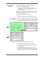
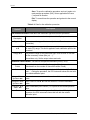
1
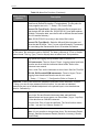
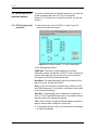
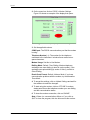
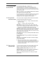
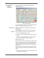
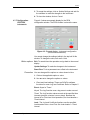
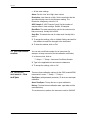
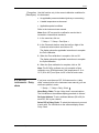
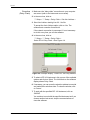
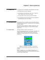
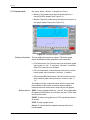
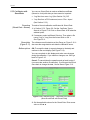
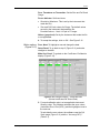
GE
Sensing
SiCalPro
Monitor and control software
User manual - K0452
Issue 1
Safety
Before you use the SiCalPro software program, make sure that
you read and understand all the related data. This includes: the
applicable local safety procedures, the instructions for the
equipment you are using with the software, and this
publication.
When you use equipment with this software, make sure that it
is serviceable and that it is in its normal condition for safe
operation.
Before you start an operation or procedure in this publication,
make sure that you have the necessary skills (if necessary, with
qualifications from an approved training establishment). Follow
good engineering practice at all times.
Copyright
© 2008 General Electric Company. All rights reserved.
The SiCalPro software uses a National InstrumentsTM
LabWindowsTM/CVITM Run-Time Engine. © 2008 National
Instruments Corporation. All rights reserved.
Trademarks
All product names are trademarks of their respective
companies.
Microsoft, Excel, and Windows are either registered
trademarks or trademarks of Microsoft Corporation in the
United States and/or other countries.
InstallShield is a registered trademark and service mark of
InstallShield Software Corporation in the United States and/or
other countries.
ii
Issue 1
Software purpose
The SiCalPro software is a virtual instrument panel that lets you
control and/or monitor a range of GE instruments from your
computer. Modem and internet facilities are available. The
software works with these instruments:
•
PC6-IDOS/PC6-IS pressure calibrator: monitor output,
control the instrument, change the configuration
•
DPI 104/DPI 104-IS pressure indicator: monitor output,
change the configuration, monitor a set of units (Safe area
only: up to 99 in a “daisy chain”)
•
IDOS pressure module (IDOS module): monitor output, set
tare, set the zero/span
•
Digital pressure module (DPM): monitor output; set tare, set
the zero/span
You can also use the software for these tasks:
Registration
•
Save records of the instrument operation in log files. You
can then see and/or print the results (as text or as a graph).
•
Design, save and print a calibration certificate. This can use
live data or data from saved log files.
•
Convert data files to *.xls and *.doc format.
•
PC6-IDOS/PC6-IS only: For applicable units under test
(UUT), set up or change a calibration procedure. The UUT
can then import the new procedure file.
The SiCalPro software is automatically registered when you
purchase it. The copy of the software that you receive will work
with all the instruments specified at the time of purchase.
Note: To use the software, it must have the serial number for
each instrument you want to use it with. To add a new
instrument, please contact us at www.gesensing.com.
iii
Issue 1
Table of Contents
Safety. . . . . . . . . . . . . . . . . . . . . . . . . . . . . . . . . . . . . . . . . . . . . . . . . . . . . . . . . . . . . . . . . . . .ii
Copyright . . . . . . . . . . . . . . . . . . . . . . . . . . . . . . . . . . . . . . . . . . . . . . . . . . . . . . . . . . . . . . . . .ii
Trademarks . . . . . . . . . . . . . . . . . . . . . . . . . . . . . . . . . . . . . . . . . . . . . . . . . . . . . . . . . . . . . . .ii
Software purpose . . . . . . . . . . . . . . . . . . . . . . . . . . . . . . . . . . . . . . . . . . . . . . . . . . . . . . . . . . iii
Registration . . . . . . . . . . . . . . . . . . . . . . . . . . . . . . . . . . . . . . . . . . . . . . . . . . . . . . . . . . . . . . iii
Table of Contents . . . . . . . . . . . . . . . . . . . . . . . . . . . . . . . . . . . . . . . . . . . . . . . . . . . . . . . . . . iv
Chapter 1: Installation
1.1 System specification . . . . . . . . . . . . . . . . . . . . . . . . . . . . . . . . . . . . . . . . . . . . . . . . . 1-1
1.2 Install SiCalPro software . . . . . . . . . . . . . . . . . . . . . . . . . . . . . . . . . . . . . . . . . . . . . . 1-1
1.3 After installation. . . . . . . . . . . . . . . . . . . . . . . . . . . . . . . . . . . . . . . . . . . . . . . . . . . . . 1-2
1.4 Remove the SiCalPro software . . . . . . . . . . . . . . . . . . . . . . . . . . . . . . . . . . . . . . . . . 1-2
Chapter 2: Getting started
2.1 Introduction . . . . . . . . . . . . . . . . . . . . . . . . . . . . . . . . . . . . . . . . . . . . . . . . . . . . . . . . 2-1
2.2 Start the software . . . . . . . . . . . . . . . . . . . . . . . . . . . . . . . . . . . . . . . . . . . . . . . . . . . . 2-1
2.2.1
2.2.2
2.2.3
2.2.4
General start up procedure . . . . . . . . . . . . . . . . . . . . . . . . . . . . . . . . . . . . . . . 2-1
Start up - Program group . . . . . . . . . . . . . . . . . . . . . . . . . . . . . . . . . . . . . . . . 2-2
Start up - Displays. . . . . . . . . . . . . . . . . . . . . . . . . . . . . . . . . . . . . . . . . . . . . . 2-2
Start up - Language . . . . . . . . . . . . . . . . . . . . . . . . . . . . . . . . . . . . . . . . . . . . 2-4
2.3 The menu options . . . . . . . . . . . . . . . . . . . . . . . . . . . . . . . . . . . . . . . . . . . . . . . . . . . 2-4
Chapter 3: Instrument communications
3.1 Introduction . . . . . . . . . . . . . . . . . . . . . . . . . . . . . . . . . . . . . . . . . . . . . . . . . . . . . . . . 3-1
3.2 Connections to the instrument. . . . . . . . . . . . . . . . . . . . . . . . . . . . . . . . . . . . . . . . . 3-1
3.3 Set up the RS232 communications . . . . . . . . . . . . . . . . . . . . . . . . . . . . . . . . . . . . . 3-2
3.3.1
3.3.2
RS232 configuration procedure . . . . . . . . . . . . . . . . . . . . . . . . . . . . . . . . . . . 3-2
Test for RS232 communications. . . . . . . . . . . . . . . . . . . . . . . . . . . . . . . . . . . 3-3
3.4 Set up modem communications. . . . . . . . . . . . . . . . . . . . . . . . . . . . . . . . . . . . . . . . 3-3
3.4.1
3.4.2
Set up the local modem . . . . . . . . . . . . . . . . . . . . . . . . . . . . . . . . . . . . . . . . . 3-3
Software settings for the Modem . . . . . . . . . . . . . . . . . . . . . . . . . . . . . . . . . . 3-3
3.5 Instrument data on the internet . . . . . . . . . . . . . . . . . . . . . . . . . . . . . . . . . . . . . . . . 3-5
3.5.1
3.5.2
Set up the data from the instrument . . . . . . . . . . . . . . . . . . . . . . . . . . . . . . . . 3-5
Log in to see the instrument data . . . . . . . . . . . . . . . . . . . . . . . . . . . . . . . . . . 3-5
iv
Issue 1
Chapter 4: Instrument configuration
4.1 Introduction . . . . . . . . . . . . . . . . . . . . . . . . . . . . . . . . . . . . . . . . . . . . . . . . . . . . . . . . 4-1
4.2 Configuration - Set or show settings . . . . . . . . . . . . . . . . . . . . . . . . . . . . . . . . . . . . 4-1
4.2.1
4.2.2
4.2.3
Configuration - PC6 instruments. . . . . . . . . . . . . . . . . . . . . . . . . . . . . . . . . . . 4-1
Configuration - DPI 104 instruments. . . . . . . . . . . . . . . . . . . . . . . . . . . . . . . . 4-2
Configuration - IDOS/DPM instruments . . . . . . . . . . . . . . . . . . . . . . . . . . . . . 4-3
4.3 Set a certificate number . . . . . . . . . . . . . . . . . . . . . . . . . . . . . . . . . . . . . . . . . . . . . . 4-4
4.4 IDOS/DPM instruments - Zero and Span . . . . . . . . . . . . . . . . . . . . . . . . . . . . . . . . . 4-4
4.5 DPI 104 instruments - Daisy chain . . . . . . . . . . . . . . . . . . . . . . . . . . . . . . . . . . . . . . 4-5
Chapter 5: Menu operations
5.1 Introduction . . . . . . . . . . . . . . . . . . . . . . . . . . . . . . . . . . . . . . . . . . . . . . . . . . . . . . . . 5-1
5.2 Mode operations . . . . . . . . . . . . . . . . . . . . . . . . . . . . . . . . . . . . . . . . . . . . . . . . . . . . 5-1
5.2.1
5.2.2
Control Mode . . . . . . . . . . . . . . . . . . . . . . . . . . . . . . . . . . . . . . . . . . . . . . . . . 5-1
Monitor Mode . . . . . . . . . . . . . . . . . . . . . . . . . . . . . . . . . . . . . . . . . . . . . . . . . 5-2
5.3 File operations . . . . . . . . . . . . . . . . . . . . . . . . . . . . . . . . . . . . . . . . . . . . . . . . . . . . . . 5-3
5.3.1
5.3.2
5.3.3
5.3.4
5.3.5
View files. . . . . . . . . . . . . . . . . . . . . . . . . . . . . . . . . . . . . . . . . . . . . . . . . . . . . 5-3
Delete files . . . . . . . . . . . . . . . . . . . . . . . . . . . . . . . . . . . . . . . . . . . . . . . . . . . 5-4
Import files . . . . . . . . . . . . . . . . . . . . . . . . . . . . . . . . . . . . . . . . . . . . . . . . . . . 5-4
Print files . . . . . . . . . . . . . . . . . . . . . . . . . . . . . . . . . . . . . . . . . . . . . . . . . . . . . 5-5
Convert files . . . . . . . . . . . . . . . . . . . . . . . . . . . . . . . . . . . . . . . . . . . . . . . . . . 5-5
5.4 Log! operations . . . . . . . . . . . . . . . . . . . . . . . . . . . . . . . . . . . . . . . . . . . . . . . . . . . . . 5-6
5.5 Certificate operations . . . . . . . . . . . . . . . . . . . . . . . . . . . . . . . . . . . . . . . . . . . . . . . . 5-9
5.5.1
5.5.2
5.5.3
5.5.4
5.5.5
5.5.6
5.5.7
5.5.8
Set a Certificate password . . . . . . . . . . . . . . . . . . . . . . . . . . . . . . . . . . . . . . . 5-9
New calibration certificates . . . . . . . . . . . . . . . . . . . . . . . . . . . . . . . . . . . . . . . 5-9
Certificates with Stored Data . . . . . . . . . . . . . . . . . . . . . . . . . . . . . . . . . . . . 5-12
Certificates with Live Data . . . . . . . . . . . . . . . . . . . . . . . . . . . . . . . . . . . . . . 5-15
Edit calibration certificates . . . . . . . . . . . . . . . . . . . . . . . . . . . . . . . . . . . . . . 5-19
Certificates - View before you print . . . . . . . . . . . . . . . . . . . . . . . . . . . . . . . . 5-20
Print a certificate . . . . . . . . . . . . . . . . . . . . . . . . . . . . . . . . . . . . . . . . . . . . . . 5-21
Delete a certificate . . . . . . . . . . . . . . . . . . . . . . . . . . . . . . . . . . . . . . . . . . . . 5-22
Chapter 6: Calibration procedures (for PC 6 instruments)
6.1 Introduction . . . . . . . . . . . . . . . . . . . . . . . . . . . . . . . . . . . . . . . . . . . . . . . . . . . . . . . . 6-1
6.2 New calibration procedures . . . . . . . . . . . . . . . . . . . . . . . . . . . . . . . . . . . . . . . . . . . 6-1
6.3 Edit calibration procedures . . . . . . . . . . . . . . . . . . . . . . . . . . . . . . . . . . . . . . . . . . . 6-3
Customer service. . . . . . . . . . . . . . . . . . . . . . . . . . . . . . . . . . . . . . . . . . . . . . . . . . . . . Back cover
v
Chapter 1: Installation
1.1 System
specification
1.2 Install SiCalPro
software
To use the SiCalPro software, this is the minimum specification
for your computer:
•
Operating system: Windows 95, Windows 98,
Windows 2000, Windows NT 4.0 or Windows XP
•
66 MHz processor (Intel® Pentium® processors
recommended)
•
128 MB of RAM (256 MB recommended)
•
CD-ROM drive or DVD-ROM drive
Before you install the software, close all other Windows
applications.
1. Insert the CD into the CD-ROM drive
Note: If your computer is not set up to open a CD
automatically, you must open the file from the CD yourself.
Double-click the file setup.exe
2. When the InstallShield® Wizard opens on your computer,
follow the on-screen instructions.
To prevent error messages, we recommend that you do not
change the default directories:
•
C:\sicalpro
•
C:\WINNT\sytem32\CVIRTE
•
C:\Program Files\National Instruments
3. To install the National InstrumentsTM LabWindowsTM/CVITM
Run-Time Engine, the installation can include these steps:
Installation
•
Insert Source: Click on Cancel. To use the SiCalPro
software, the Device Drivers CD is not necessary.
•
Installation Complete: Click on Finish. To use the SiCalPro
software, there is no additional activation.
1-1
Issue 1
1.3 After installation
When the installation is complete, you can do the following:
•
Chapter 2: Start the SiCalPro software. You can run more
than one copy of the software at the same time; one for
each instrument connected to the computer.
•
Chapter 3: Connect the applicable instrument or instruments
to your computer.
Caution! To prevent electrical damage when you
connect or disconnect the RS232 connection on your
computer, make sure the instrument power is set to off.
•
1.4 Remove the
SiCalPro software
Chapter 4: Set up and use the software with the applicable
instruments.
If it is necessary to remove the software from a computer, there
are two programs to remove: SiCalPro and the related Real
Time Engine. Use these steps to remove each program from
your computer:
1. On the Windows taskbar, click on the Start button and select
Settings > Control Panel > Add/Remove Programs.
2. Select the software program (SiCalPro or National
Instruments Software) and select the “Remove” option.
3. Follow the on-screen instructions.
1-2
Installation
Chapter 2: Getting started
2.1 Introduction
This chapter gives a description of these items:
•
the procedure to start the SiCalPro software
•
the start up displays
•
the procedure to set a different language
•
the menu structure and options
2.2 Start the
software
You can run more than one copy of the software at the same
time; one for each instrument connected to the computer.
2.2.1 General start up
procedure
1. On the Windows task bar, click on the Start button and
select Programs > SiCalPro > SiCalPro.
Figure 2-1: Example display - OFFLINE
2. Connect the instrument to a RS232 communications port on
your computer. Refer to Chapter 3.
Caution! To prevent electrical damage when you
connect or disconnect the RS232 connection on your
computer, make sure the instrument power is set to off.
3. To start communication between the SiCalPro software and
the instrument, click on OFFLINE.
Getting started
2-1
Issue 1
2.2.2 Start up - Program
group
Figure 2-2 shows the program group (Start > Programs >
SiCalPro):
NILWCVIRTE***: This re-installs the Run Time Engine.
SiCalPro: This starts the SiCalPro software. If you right-click
on this option, you can make a shortcut to put on your desktop.
vbdde: This starts a server connection to use the software over
a computer network.
Figure 2-2: SiCalPro program group
2.2.3 Start up - Displays
When you start the software, Figure 2-3 gives an example of
the OFFLINE window that opens for each type of instrument.
Table 2-1: Key to Figure 2-3
Item
2-2
Description
(1)
Menu bar (All instruments): To select a task from a menu list. There is a
standard set of menu options plus special options for the different instruments.
Refer to Section 2.3.
(2)
Analogue pressure gauge (PC6, IDOS module/DPM instruments only): To show
the pressure values measured by the instrument.
(3)
Simulation display and keypad (PC6 instruments only). To simulate the display
and control functions on the instrument. The keypad is not available (greyed out)
in MONITOR mode.
(4)
Maximum and Minimum (All): To show the maximum and minimum pressures
measured by the instrument.
(5)
Unit mode (PC6, DPI 104 instruments only): The mode gives an indication of the
operations available.
•
PC6 instruments: CONTROL (the PC6 simulation keypad is available) or
MONITOR (the monitor and log operations are available). This is set by menu
Mode.
•
DPI 104 instruments: NORMAL (the monitor and log operations are
available) or Daisy Chain (the daisy chain functions are available).
(6)
Communications status (All): The ONLINE/OFFLINE button starts or stops the
SiCalPro communications with the instrument. If the instrument power is off and
it has an internal power on function, ONLINE sets the power on.
(7)
QUIT button (All): To close the SiCalPro software.
Getting started
Issue 1
Table 2-1: Key to Figure 2-3 (Continued)
Item
Description
(8)
Simulation display (DPI 104 instruments only): To simulate the display functions
on the instrument.
(9)
Output panel (IDOS module/DPM instruments only): To show the output from
the instrument.
(10)
Tare button (IDOS module/DPM instruments only): To make an adjustment for
atmospheric pressure and set the pressure value to zero. The tare value is reset
each time the instrument goes ONLINE.
(11)
Reset Max/Min button (IDOS module/DPM instruments only): To reset the
maximum and minimum pressure values to zero.
1
2
3
4
8
5
6
7
(a) PC6-IDOS/PC6-IS:
Special and common SiCalPro functions
(b) DPI 104/DPI 104-IS (Part only):
Special SiCalPro functions
9
* Note: The DPM
has almost the
same display as
the IDOS module
10
11
(c) IDOS module (Part only)*:
Special SiCalPro functions
Figure 2-3: Example start up displays - Main functions
Getting started
2-3
Issue 1
2.2.4 Start up - Language The software can operate in these languages: English,
German, French, Spanish, Italian.
To change the language, use the menu bar:
Select *** Setup > Language and set the applicable option.
(Where *** = PC6 Pro; DPI 104, IDOS, DPM)
Note: For correct operation, make sure you are using the same
language on the instrument.
2.3 The menu options
Table 2-2 gives a description of the menu options available with
all the instrument types.
Note: Some of the fields that you are permitted to change
contain hidden characters. If you want to change these fields
(text or numeric values), highlight all the applicable characters
and overwrite them.
Table 2-2: Menu Bar Functions
Menu Heading/
Options
Description
Mode: Sets the operations available with the instrument. The default mode of operation is
Monitor (Text) mode. To use this menu, the instrument must be ONLINE.
Control
(PC6 instruments only) In this mode, you can use the MENU, UP,
DOWN, ENTER, PRINT/LOG, and ON/OFF buttons to simulate
operations on the instrument keypad. Refer to the instrument user
manual.
Note: The Log! menu is not available in Control mode. If necessary,
store the data on the PC6 instrument and export it to the SiCalPro
software later.
2-4
Getting started
Issue 1
Table 2-2: Menu Bar Functions (Continued)
Menu Heading/
Options
Monitor
Description
Two options: Graphical or Text.
Graphical: To monitor the instrument output in a two-graph window
format. Top graph: pressure values; bottom graph: an additional value
applicable to the instrument.
•
PC6 instruments: Use Control mode to set the bottom graph value
(volts, mV, mA, °C, maximum, minimum, % and tare). Other PC6
values are not available.
•
DPI 104 instruments: Use the Bottom Line menu to set the bottom
graph value (maximum, minimum, %, switch).
•
IDOS module/DPM instruments: Use the Function menu to set the
bottom graph value (maximum, minimum, tare, %, °C).
Buttons: EXIT (To go back to the normal display), STOP (stop a graph
record), START (start a new graph record), SAVE (save a graph record
to a *.mon file).
Text (Default): To monitor the instrument output on a normal SiCalPro
display (Figure 2-3). The PC6 keypad is not available in Monitor mode.
Refer to Section 5.2.
File: To work with the data files saved for an instrument (*.imp, *.mon, *.log files only). The
*.imp files from a PC6 instrument contain data from a completed calibration procedure or
normal log data.
View
Two options: Graphical or Text.
Graphical: To show a graph and related data for all the records saved
in a file. You can go through the records (▲ ▼), Print and Cancel.
Text: To show the data for each record saved in a file. You can go
through the records (Prev., Next) and Close.
Delete
To delete a file (with a two-step approval)
Import
(PC6 instruments only) To import a log file (*.imp) from a connected
PC6 instrument. To prevent errors, make sure you use the file export
procedure for the PC6 instrument. Refer to the instrument user manual.
Print
To print a file to the default printer for your computer. The file prints as
unformatted text. If the output is incorrect, adjust the printer settings or
use the option File > View > Graphical > Print.
Getting started
2-5
Issue 1
Table 2-2: Menu Bar Functions (Continued)
Menu Heading/
Options
Convert
Description
To convert a file (*.imp, *.mon, *.log) to Microsoft® Excel® or Microsoft®
Word format (Default file location: c:\sicalpro\data). The file paths for
these programs are set in: *** Setup > File Convert Path.
Convert File Type (Excel): Starts the Microsoft Excel program and
puts the data into the default file: SICALPRO.XLS (new data replaces
old data). To keep the data, save the file with a different filename and/or
save it to another directory.
Note: SICALPRO.XLS must stay in the default file location.
Convert File Type (Word): Starts the Microsoft Word program and
saves the data in the file: *.doc (* is your original filename). If necessary,
you can change the filename and move it to another file location.
Log! To make a permanent record of the instrument operation (normal Log or Leak Test). To
use this menu, the instrument must be ONLINE. The data is collected in a Text or Graphic
window format. The Log Type (Timed or Keyed) does not affect Leak Test operations.
Log! opens the Logging Set up window. Refer to Section 5.4.
PC6 instruments: Timed or Keyed; Timed - Logging Interval and Leak
Duration are all set with the instrument Menu button. Refer to the
instrument user manual.
To do a Leak Test, set the instrument to show Leak: Start Set-Time Exit
DPI 104, IDOS module/DPM instruments: Timed or Keyed; Timed Logging Interval and Leak Duration are all set in menu:
*** Setup > *** Setup > *** Configuration (Refer to Chapter 4)
Certificate: To set up and control the calibration certificates for an instrument. In menu
*** Setup, you can set up a password for this function. You can also set standard
header/footer text; set a standard adjustment to the printed layout; set a standard user
name for Calibrated by: ... .
New
Two certificate options: Normal or Leak
Type in the Test and Standard instrument data; add certificate
headers/footers and a user name; use Stored data (*.log or *.imp files)
or Live data from an ONLINE instrument.
You can View, Print or Save the certificate. The Save function makes
two files: *.cer and *.txt. Refer to Section 5.5.
Edit
To change a certificate.
Note: It is not possible to change these items: Test Instrument Details
(Range); Standard Instrument Details (Serial No, Accuracy); Results
(Stored Data).
2-6
Getting started
Issue 1
Table 2-2: Menu Bar Functions (Continued)
Menu Heading/
Options
Description
Print
To print a certificate to the default printer for your computer. Refer to
Section 5.5
Delete
To delete a certificate. This deletes the *.cer and the related *.txt file
(with a two-step approval).
RS232: To set up the RS232 communications and do tests for correct operation, or to set up
communications for a modem. The modem facility lets you communicate with an instrument
through the telephone system.
Config
To set up the communications between the SiCalPro software and the
RS232 port used by the instrument (for example: COM1). The settings
must be correct for the instrument. Refer to Chapter 3.
Test
To do a test for RS232 communications between the computer and the
instrument:
OK - Port settings correct; instrument ONLINE
No communication - Instrument OFFLINE
Failed - Port settings, power supply or connections are not correct
Modem Settings
To use this menu, the communications must be OFFLINE. Set the
applicable values for COMS port, Telephone Number (with area codes
but no space characters), Modem Usage, Dialling Mode, Result Code
Format. Refer to Chapter 3.
*** Setup: There is a standard set of options plus special options for the different
instruments.
Change Password To set, change or remove the password for menu Certificate.
Passwords are case sensitive. Default: no password.
You must confirm a New Password. Use the tab key or click on an
available option (Enter New Password, Re-enter New Password;
Remove Password ... No ▼).
If you lose your password, contact us at www.gesensing.com.
Getting started
2-7
Issue 1
Table 2-2: Menu Bar Functions (Continued)
Menu Heading/
Options
*** Setup Description
To set and/or see configuration options for the connected instrument;
set an instrument certificate number (for example: the last calibration
certificate); set applicable special instrument options:
DPI 104: Daisy Chain. If you have more than one DPI 104 instrument in
a network, these options are available: Abort Daisy Chain (to stop daisy
chain communications); Set Auto Address (to set addresses 00 to 99);
Select DPI ... (to select the instrument you want to work with).
IDOS module/DPM instruments: Zero/Span (to do a zero and span
calibration); Abort Zero/Span (to stop the calibration); History (to show
the last calibration date, span date and the overload history)
Refer to Chapter 4.
Software Setup
This gives data about the SiCalPro software version and the instrument
it communicates with:
Software Serial No (the serial number of the instrument);
Issue date (the software version date);
Language (the software language specified in *** Setup > Language);
Type (the instrument type).
Edition (Full or Demo). You can use a Demo version 30 times.
Internet Copy (Yes or No). An internet copy can send data to an internet
server. Refer to Chapter 3
Certificate Layout To set the Header offset (1 to 10) for your certificates. If you use
preprinted paper, set a value that stops the first line of the certificate
overwriting standard text and logos.
1 = Certificate starts on line 1.
Certificate
Header/Footer
User Names
To set up standard header and footer text for New certificates. Header
text goes above the Results section; footer text goes below the Results
section. Set the applicable text On or Off and click on Update.
To set up user names (1 to 10) for the Certificate function.
To change a name, highlight the text and overwrite it. To set a default
name for New certificates, use the Active User buttons (▲ ▼).
File Convert Path To set up the file paths for the Microsoft Excel and Microsoft Word
programs. If you use menu File > Convert, the SiCalPro software uses
the specified locations to find these programs.
Language To change the default language for the software.
Note: For correct operation, make sure you are using the same
language on the instrument.
2-8
Getting started
Issue 1
Table 2-2: Menu Bar Functions (Continued)
Menu Heading/
Options
Units
Description
(IDOS module/DPM instruments only) To set up two more pressure
units:
User defined unit 1 (or unit 2) text: Up to 6 characters.
User defined unit 1 (or unit 2) conversion factor: An applicable
value that changes the pressure (in bar) to another pressure unit.
To update the standard Units list (on the menu bar), Save the new units.
If a name is already used by a standard unit, the new unit is ignored.
Note: These units are only available in the SiCalPro software. They are
not saved in the instrument. If you use the software on more than one
computer, set up the new units in each copy.
Internet
(Optional software for a Windows NT network that supports Active
Server Pages - contact us at www.gesensing.com) This option lets you
send instrument display data to an internet server. Another user can
then use the internet to log in and monitor the data.
You must set applicable values for Web address, Password, File
Update rate, Screen Refresh rate, Maximum no. of records. Refer to
Chapter 3.
Units (DPI 104 and IDOS module/DPM instruments only): To change the instrument’s
pressure units to another unit on the list (mbar, psi, MPa ...). To use this menu, the
instrument must be ONLINE.
UNIT 1
UNIT 2
(IDOS module/DPM instruments only). Two pressure units specified in
menu *** Setup > Units.
Bottom Line (DPI 104 instruments) OR
Function (IDOS module/DPM instruments): To set the value for the bottom graph that
you see in menu Mode > Monitor > Graphical. The pressure units are the same as in menu
Units.
Maximum
Maximum pressure
Minimum
Minimum pressure
Percentage
Switch
Tare
Temperature
Getting started
Pressure as a percentage of the full scale output
(DPI 104 instruments only) Pressure values to open/close a switch
(IDOS module/DPM instruments only) Tare pressure
(IDOS module/DPM instruments only) °C values from the instrument
sensor
2-9
Issue 1
Table 2-2: Menu Bar Functions (Continued)
Menu Heading/
Options
Description
Calibration procedure (PC6 instruments only): To set up and control the calibration
procedures for an instrument.
New
To set up a new calibration procedure. This includes File Name; Test
Instrument Details; Calibration Point Details and related text (to give
procedure instructions).
When the procedure is complete, click on the applicable button: Print,
Export, Save, Exit. See below.
Print: To print the procedure.
Export: To export a calibration procedure to a PC6 instrument. The
instrument must be ONLINE and it must be in the correct menu to
import a file. Refer to the instrument user manual.
Save: To save the procedure to a *.cal file.
Exit: To go back to the normal display.
Refer to Chapter 6.
Edit
2-10
To change a calibration procedure file (*.cal). When the changes are
complete, click on the applicable button: Print, Export, Save, Exit
Getting started
Chapter 3: Instrument
communications
3.1 Introduction
3.2 Connections to
the instrument
This chapter gives a description of these items:
•
how to make the RS232 connections to an instrument
•
how to set up the RS232 communications and use the test
function
•
how to set up modem communications with an instrument
•
(internet option) how you can send instrument data to an
internet server
Caution! To prevent electrical damage when you
connect or disconnect the RS232 connection on your
computer, make sure the instrument power is set to off.
Each instrument has an 8-way circular miniature connector. To
connect an instrument to the 9-way D type RS232
communication port on your computer, use an applicable cable
(Figure 3-1).
Power supply connector
(Not applicable to PC6 instruments)
8-way connector
(instrument)
9-way D type connector
(computer)
Figure 3-1: Example RS232 connection
(instrument to computer)
For the applicable connection instructions, refer to the user
manuals for the instrument and the computer.
Instrument communications
3-1
Issue 1
3.3 Set up the RS232
communications
To use this software with an attached instrument, you must set
up the necessary data for the PC Port Configuration
(Figure 3-2). To make sure it is working correctly, use the test
function.
3.3.1 RS232 configuration
procedure
1. On the menu bar, click on RS232 > Config. Figure 3-2
shows the window that opens.
Figure 3-2: Example display - PC port configuration
2. Set the applicable values:
COMS port: The RS232 communications port that the
instrument is using. Usually this is COM1. To use a computer to
monitor more than one instrument at a time, you must have
more than one RS232 communications port.
Baud Rate: The data transmission rate for the instrument (in
bits per second). Usually this is 9600.
Note: For the IDOS module, the baud rate is 19200; for PC6
and DPM instruments, it is possible to set different rates (refer
to the instrument settings).
Stop Bits: To indicate the end of a data word. Usually this is
set to 1. For PC6 and DPM instruments, it is possible to have 2
stop bits (refer to the instrument settings).
CTS: (Clear to Send). A signal to indicate that the computer is
ready to receive data. Usually this is set to ON.
3. To accept the settings, click on OK and wait for the software
to make the changes.
3-2
Instrument communications
Issue 1
4. If you get a Failed message, make sure the Windows
system has the same settings for the specified COM port:
Baud Rate = instrument value;
Stop Bits = instrument value;
Data bits = 8; Parity = None; Flow control = None
Note: To change the COM port settings in your Windows
system, refer to your computer instructions or contact your
system administrator.
3.3.2 Test for RS232
communications
To do a test on the RS232 communications:
1. On the menu bar, click on RS232 > Test.
One of these results will appear:
OK - Port settings correct; instrument ONLINE
No communication - Instrument OFFLINE
Failed - Port settings, power supply or connections are not
correct
2. If necessary, make changes to your settings or connections.
3.4 Set up modem
communications
3.4.1 Set up the local
modem
This facility makes it possible to communicate with an
instrument through the telephone system. You must have two
modems:
•
a local modem connected to your computer (the computer
with the SiCalPro software)
•
a modem connected to the instrument - refer to your modem
instructions
1. Set up or select the modem for your computer (for example:
Start > Settings > Control Panel > [... Modem ...]). Refer to
your computer instructions or contact your system
administrator.
Note: To use the modem function with an IDOS module, the
baud rate must be 19200. To use the modem function with the
other instruments, the baud rate must be 9600.
2. Keep a record of the specified COM port (if applicable, click
on the specified modem and click on Properties).
3.4.2 Software settings
for the Modem
To use this software with the attached modem, you must set up
the necessary data for the Modem Settings (Figure 3-3).
1. Make sure the software is OFFLINE. It is not possible to
open the menu option ONLINE. This prevents corruption of
your software settings.
Instrument communications
3-3
Issue 1
2. On the menu bar, click on RS232 > Modem Settings.
Figure 3-3 shows an example of the display that opens.
Figure 3-3: Example display - Modem Settings
3. Set the applicable values:
COMS port: The RS232 communications port that the modem
is using.
Telephone Number (...): The number for the telephone
connected to the instrument. Include all area codes but no
space characters.
Modem Usage: Set this to Use Modem.
Dialling Mode: Default: Tone Dialling. Modern telephone
exchanges use tone dialling (a tone for each number). If the
exchange uses pulse dialling (a series of 'clicks'), set this to
Pulse Dialling.
Result Code Format: Default: Verbose Mode. If you have
communication problems with the modem, try the alternative
Terse Mode.
4. To accept the settings, click on Update Settings and wait for
the software to make the changes.
5. To start using the modem, click on OFFLINE. A modem
status panel shows the telephone number your are dialling
and the communication status.
6. To close the modem connection, click on ONLINE.
Note: If there is a communications failure or if you click on
QUIT to close the program, this also disconnects the modem.
3-4
Instrument communications
Issue 1
3.5 Instrument data
on the internet
(For the internet option only - Contact us at
www.gesensing.com) This option lets you send a 2-line
instrument display (in real-time) to a specified data file on an
internet server. Another user can then use the internet to log in
and monitor the data.
Note: This software is only available for Windows NT networks
that support Active Server Pages (ASP).
For correct operation, the software installation for the computer
and the internet server must occur together. Refer to the
installation instructions supplied with the software.
3.5.1 Set up the data
You must set up the computer with the instrument connection
from the instrument to send the instrument data to the internet:
1. On the menu bar, click on *** Setup > Internet and set the
applicable values:
(Where *** = PC6 Pro; DPI 104, IDOS, DPM)
Web address: (Agreed with the system administrator) The
server location to which the SiCalPro software sends the data.
Example: http://SERVER NAME/sicalpro/extract.asp.
Password: (Agreed with the system administrator) A password
that is sent with the instrument data to the server. To see the
data, the other user must know the approved Password and the
Serial Number for the instrument.
File Update rate: The rate (in seconds) at which data is sent to
the web address.
Screen Refresh rate: The rate at which the internet page is
refreshed.
Maximum no. of records: The number of records to display
on the internet display.
2. When the Internet data is set up correctly, the software
sends the instrument data to the specified web address. The
instrument data includes the approved password, and the
instrument serial number.
3.5.2 Log in to see the
instrument data
To see the instrument data on the internet page correctly, the
display and printer properties must have these settings:
Display resolution (Screen size): Set to 1024 x 768
Specified Printer: Set the output orientation to landscape. In
portrait, the right hand side of the display is cut off.
Refer to your computer instructions or contact your system
administrator.
Instrument communications
3-5
Issue 1
When instrument data is available, use these steps to log in:
1. Type in the internet path to view the data.
Example: http://SERVER NAME/sicalpro/login.asp
2. On the login display, type in the approved Password and the
instrument Serial Number.
3-6
Instrument communications
Chapter 4: Instrument configuration
4.1 Introduction
This chapter gives a description of these items:
•
the instrument configuration options in menu:
*** Setup > *** Setup > *** Configuration
(Where *** = PC6 Pro; DPI 104, IDOS, DPM)
4.2 Configuration Set or show settings
•
the procedure to set an instrument certificate number
•
the special instrument options: Zero and Span
(IDOS module/DPM); Daisy chain (DPI 104).
If you want to set or see the configuration settings for an
instrument use menu:
*** Setup > *** Setup > *** Configuration
To use this menu, the instrument must be ONLINE.
4.2.1 Configuration - PC6
instruments
Figure 4-1 shows an example display for the PC6 configuration
window.
Figure 4-1: Example display - Instrument configuration
(PC6 Instruments)
It is not possible to change the PC6 settings in this window
(Language; Resolution; Log Status). To make changes to the
instrument configuration, use menu:
Mode > Control. Refer to Section 5.2.1.
Instrument configuration
4-1
Issue 1
4.2.2 Configuration DPI 104
instruments
Figure 4-2 shows an example display for the DPI 104
configuration window.
Figure 4-2: Example display - Instrument configuration
(DPI 104 Instruments)
You cannot change the settings (white) in the top half of this
window. To change the units, use menu: Units
Button options Cancel: To cancel/close the operation and go back to the
normal display.
Update Settings: To make the changes to the instrument.
Procedure You can change all the options or values shown in blue:
1. Click on the applicable option or value.
2. Use ▲ or ▼ (screen or keyboard) to change the options or
values.
•
Event and Leak settings: SiCalPro software functions for
menu Log! and Certificate. Refer to Chapter 5.
Event: Keyed or Timed.
Keyed: The Log! function uses a key press to make a record.
Timed: The Log! function makes records at the specified time
intervals (seconds, minutes, hours or days). Because the
interval is for Timed and Leak operations, set Leak duration ≥
Timed interval.
Leak: The Log! and Certificate functions use the specified
Leak duration to do a Leak Test. Set Leak duration ≥ Timed
interval.
•
4-2
All the other settings: DPI 104 instrument functions (refer to
the instrument user manual)
Instrument configuration
Issue 1
3. To accept the settings, click on Update Settings and wait for
the software to make the changes to the instrument.
4. To close the window, click on Cancel.
4.2.3 Configuration IDOS/DPM
instruments
Figure 4-3 shows an example display for the DPM
configuration window. The IDOS module is almost the same.
Figure 4-3: Example display - Instrument configuration
(IDOS/DPM Instruments)
You cannot change the settings (white) in the top half of this
window. To change the units, use menu: Units
Button options Exit: To cancel/close the operation and go back to the normal
display.
Update Settings: To make the changes to the instrument.
Reset Zero: To do a permanent zero offset to the instrument.
Procedure You can change all the options or values shown in blue:
1. Click on the applicable option or value.
2. Use ▲ or ▼ to change the options or values:
•
Event and Leak settings: These are SiCalPro software
functions for menu Log! and Certificate. Refer to Chapter 5.
Event: Keyed or Timed.
Keyed: The Log! function uses a key press to make a record.
Timed: The Log! function makes records at the specified time
intervals (seconds, minutes, hours or days). Because the
interval is for Timed and Leak operations, set Leak duration ≥
Timed interval.
Leak: The Log! and Certificate functions use the specified
Leak duration to do a Leak Test. Set Leak duration ≥ Timed
interval.
Instrument configuration
4-3
Issue 1
•
All the other settings:
Alarm: Set the ‘Low’ and ‘High’ alarm values.
Resolution: Low, Normal or High. Set the resolution that the
simulation display uses for the pressure reading. The
Resolution changes by a factor of 10.
ADC Sample C: (ADC Sample Count) Set the number of
samples taken in each average. Default: 25 samples.
Baud Rate: The data transmission rate for the instrument (in
bits per second). Usually this is 9600.
Stop Bits: To indicate the end of a data word. Usually this is
set to 1.
3. To accept the settings, click on Update Settings and wait for
the software to make the changes to the instrument.
4. To close the window, click on Exit.
4.3 Set a certificate
number
You can set a certificate number for an instrument (for
example: to keep a record of the last calibration certificate):
1. In the menu bar, click on:
*** Setup > *** Setup > Instrument Certificate Number
2. Type in the applicable text and numeric characters
3. To accept the settings, click on OK.
4.4 IDOS/DPM
instruments - Zero
and Span
There are three calibration options for the IDOS module/DPM
instruments in menu *** Setup > *** Setup > :
Zero/Span: (with password protection) To do a zero and span
calibration.
Abort Zero/Span: To stop the zero or span calibration.
History: To show the last calibration date, span date and the
overload history.
To use these menu options, the instrument must be ONLINE.
4-4
Instrument configuration
Issue 1
Procedure Use this function only in the correct calibration conditions for
(Zero/Span) the instrument:
•
An applicable pressure standard (primary or secondary)
•
A stable temperature environment
•
Applicable special conditions
Refer to the instrument user manual.
Note: Note: GE can provide a calibration service that is
traceable to international standards.
1. In the menu bar, click on:
*** Setup > *** Setup > Zero/Span >
2. In the Password window, enter the last four digits of the
instrument serial number and click on OK.
The display shows the applicable instructions to complete
the Zero calibration.
3. When the Zero calibration is complete, click on OK.
The display shows the applicable instructions to complete
the Span calibration.
4. When the Span calibration is complete, click on OK.
Note: The SiCalPro software can only complete a Span
calibration on a DPM instrument if the temperature is 10 to
30°C (50 to 86°F) and Span is ±5% of the full scale value.
4.5 DPI 104
instruments - Daisy
chain
If you have more than one DPI 104 instrument in a “daisy
chain” network (refer to the instrument user manual), you can
use these options in menu:
*** Setup > *** Setup > Daisy Chain Abort Daisy Chain: To stop “daisy chain” communications.
The Unit Mode on the software display goes back to Normal.
Set Auto Address: To set a software address (00 to 99) for
each DPI 104 in your network.
Select DPI in Daisy Chain: To select the instrument you want
to work with. The Unit Mode on the software display shows
Daisy Chain.
Instrument configuration
4-5
Issue 1
Procedure 1. Make sure the “daisy chain” connections to your computer
are correct (refer to the instrument user manual).
(Daisy Chain)
2. In the menu bar, click on:
*** Setup > *** Setup > Daisy Chain > Set Auto Address >
3. Start Auto Address starting from 00 - Yes/No:
To accept the Auto Address option, click on Yes. The
software sets a number for each unit.
If the network connection is permanent, it is not necessary
to do this every time you use the software
4. In the menu bar, click on:
*** Setup > *** Setup > Daisy Chain >
Select DPI in Daisy Chain > See Figure 4-4.
Figure 4-4: Example display - Select DPI 104 Daisy address
5. To select a DPI 104 instrument, click on one of the available
options and click on Select. The Unit Mode on the software
display shows Daisy Chain.
6. If necessary, you can move the selection window to one side
and make other selections later. To close the window, click
on Cancel.
7. To work with the specified DPI 104 instrument, click on
ONLINE.
You continue to work with the specified instrument until you
choose another instrument, stop the communications or
close the software.
4-6
Instrument configuration
Chapter 5: Menu operations
5.1 Introduction
5.2 Mode operations
This chapter gives a description of the standard menu items:
•
the Mode menu (Control or Monitor)
•
the File menu to work with your *.log; *.imp; *.mon files
(View, Delete, Import, Print, and Convert)
•
the Log! menu to save your Log and Leak Test files
•
the Certificate menu to set up and control your calibration
certificates (New, Edit, Print, Delete)
Menu Mode (Control or Monitor) sets the operations that are
available with an instrument. To use this menu, the instrument
must be ONLINE.
The default mode of operation is Monitor (Text) mode. This
shows the instrument output on a normal SiCalPro display
(Figure 2-3).
5.2.1 Control Mode
Use menu: Mode > Control > See Figure 5-1
Only PC6 instruments can use Control mode. The MENU, UP,
DOWN, ENTER, PRINT/LOG, and ON/OFF buttons are
available to simulate operations on the instrument keypad
(Figure 5-1).
Figure 5-1: Example PC6 display - Control Mode
To use the instrument keypad, refer to the instrument user
manual.
Note: The Log! menu is not available in Control mode. If
necessary, store the data on the PC6 instrument and export it
to the SiCalPro software later.
Menu operations
5-1
Issue 1
5.2.2 Monitor Mode
Use menu: Mode > Monitor (Graphical or Text) >
•
Monitor (Text) mode shows the instrument output on a
normal SiCalPro display (See Figure 2-3).
•
Monitor (Graphical) mode shows the instrument output in a
two-graph window format (See Figure 5-2).
Figure 5-2: Example display - Graphical Mode
Display information The top graph shows pressure values. The bottom graph
shows an additional value applicable to the instrument.
•
PC6 instruments: Use Control mode to set the bottom graph
value (volts, mV, mA, °C, maximum, minimum, % and tare).
Other PC6 values are not available.
•
DPI 104 instruments: Use the Bottom Line menu to set the
bottom graph value (maximum, minimum, %, switch).
•
IDOS module/DPM instruments: Use the Function menu to
set the bottom graph value (maximum, minimum, tare, %,
°C).
The display includes: instrument serial number; record start
time and date; total number of records; alarm conditions,
maximum/minimum and real-time output for the two graphs.
Button options SAVE: To save a graph record to a *.mon file. Set an applicable
file name and file location. You can then use menu File to View
and Print the results.
START: To start a new graph record. This discards the old set
of records.
STOP: To stop a graph record.
Cancel: To cancel/close the operation and go back to the
normal display.
5-2
Menu operations
Issue 1
5.3 File operations
Menu File lets you work with the data files saved for an
instrument (*.log; *.imp; *.mon files only).
You can: View, Delete, Import (PC6 instruments only), Print,
and Convert files (convert to a Microsoft Excel spreadsheet or
a Microsoft Word document).
5.3.1 View files
1. Use menu: File > View (Graphical or Text). A file selection
window opens.
2. If necessary, select a different Directory. Then select a file
name from the list and click on OK. >
•
View (Graphical) shows the specified instrument file in a
two-graph window format that includes all the records
(See Figure 5-3).
•
View (Text) shows the specified instrument file in a text
format - one record at a time (See Figure 5-4).
Figure 5-3: Example display - Graphical view
Display information The top graph shows pressure values. The bottom graph
shows an additional value applicable to the instrument. To set
the bottom graph, refer to Section 5.2.2.
The display includes: file name and location; instrument type;
instrument serial number; current record; record start time and
date/end time and date; total number of records; alarm
conditions, maximum/minimum and output values for the
current record.
Button options Print: To print the display for the specified record. A print
window lets you set the necessary print options. If there is a
print error, set the option to Use Bitmap Printing.
Menu operations
5-3
Issue 1
Record (▲ ▼): To go through the records in the file. For each
change in record, a bar moves across the two graphs.
(Alternative: Use your mouse to drag the bar across the graph).
Cancel: To cancel/close the operation and go back to the
normal display.
Figure 5-4: Example display - Text view
Display information This display shows the data one record at a time.
Button options Record Num. (▲ ▼); Prev., Next: To go through the records in
the file.
Close: To close the window and return to the normal display.
5.3.2 Delete files
1. Use menu: File > Delete. A file selection window opens.
2. If necessary, select a different Directory. Then select a file
name from the list and click on OK. >
3. Delete File Yes/No: To accept the Delete File option, click on
Yes.
5.3.3 Import files
(PC6 instruments only) Use this option to import a log file
(*.imp) from a connected PC6 instrument. The *.imp files can
contain data from a completed calibration procedure or normal
log data.
Procedure 1. Connect the PC6 instrument and click on ONLINE
2. Use the file export procedure for the PC6 instrument. Refer
to the instrument user manual.
3. Use the SiCalPro software menu: File > Import. A file
selection window opens.
4. Select a file name from the list and click on OK.
5-4
Menu operations
Issue 1
5.3.4 Print files
1. Use menu: File > Print. A file selection window opens.
2. If necessary, select a different Directory. Then select a file
name (*.log; *.imp; *.mon) from the list and click on OK. >
The file prints to the default printer for your computer as
unformatted text. If the output is incorrect, adjust the printer
settings or use the option File > View > Graphical > Print.
5.3.5 Convert files
Use this option to convert a file (*.log; *.imp; *.mon) to
Microsoft Excel or Microsoft Word format.
Note: Make sure the file paths for these programs are set up
correctly in menu: *** Set Up > File Convert Path.
Procedure 1. Use menu: File > Convert. A file selection window opens.
2. If necessary, select a different Directory. Then select a file
name from the list and click on OK. > See Figure 5-5.
Figure 5-5: Example display - Convert window
3. Select one of the options (Excel or Word) and click on OK.
> See Option 1 / Option 2
Option 1 Convert File Type (Excel): Starts the Microsoft Excel program
and puts the data into the default file: SICALPRO.XLS (new
data replaces old data).
To keep the data, save the file with a different file name and/or
save it to another directory.
Note: SICALPRO.XLS must stay in the default file location.
Option 2 Convert File Type (Word): Starts the Microsoft Word program
and saves the data in the file: *.doc (* is your original
file name).
If necessary, you can change the file name and/or move it to
another file location.
Menu operations
5-5
Issue 1
5.4 Log! operations
Menu Log! makes a permanent record of the instrument
operation (normal Log or Leak Test). To use this menu, the
instrument must be ONLINE.
The data is collected in a Text or Graphic window format
(Figure 5-7).
Starting procedure 1. Use menu: Log! > See Figure 5-6
Figure 5-6: Example display - Logging set up
2. The Log Type (Timed or Keyed Event), and leak settings
(Leak Duration and Logging Interval) are part of the
instrument set up.
•
PC6 instruments: To change the Event and Leak settings,
use the instrument Menu button (See Section 5.2.1).
•
DPI 104 and IDOS module/DPM instruments: To change the
Event and Leak settings, use menu:
*** Setup > *** Setup > *** Configuration (Chapter 4)
Procedure 1. For Log / Leak: Select Log
(Log) 2. For Display Mode: Select Graphic or Text.
Figure 5-7 shows the difference between the two options.
3. Set the applicable ... Number of Records (▲ ▼).
4. To accept the settings, click on OK.
5. In the window that opens, set a file name and file location for
the *.log file and click on OK. >
Figure 5-7 shows the type of display that you see and use for
each option (Graphic or Text - specified in step 2).
5-6
Menu operations
Issue 1
Note: Figure 5-7 shows the displays when the Log Type is
Keyed (records are made with the EVENT button). If the Log
Type is Timed, the EVENT button is greyed out.
Button options EVENT: Log Type (Keyed) only. Each time you select this key,
(Log) you make a record of the instrument values.
START: To start the sequence of records.
STOP: To stop the sequence of records. You get the option to
save the available records before the window closes.
Cancel or Abort: To cancel/close the operation and go back to
the normal display.
Figure 5-7: Example display - Log (Text or Graphic)
6. To start a set of records, click on START. >
Log Type (Keyed): Click on EVENT to make each record.
When you reach the number of records specified in step 3,
you get a Logging message (“... File stored”).
Log Type (Timed): The software uses the specified Logging
Interval until it reaches the number of records specified in
step 3. You get a Logging message (“... File stored”).
7. When you get the Logging message, click on OK. The
normal display is available again.
Procedure Note: PC6 instruments only. The instrument display must show
(Leak Test) Leak: Start Set-Time Exit (Refer to the instrument user
manual).
1. For Log / Leak: Select Leak Test
2. For Display Mode: Select Graphic or Text.
Figure 5-8 shows the difference between the two options.
3. To accept the settings, click on OK.
Menu operations
5-7
Issue 1
Note: The software uses the specified Leak Duration and
Logging Interval to set the number of records automatically.
(Minimum: 2 for the Leak Duration + 1 start record). Refer to
the Log! starting procedure.
Figure 5-8 shows the type of display that you see and use for
each option (Graphic or Text - specified in step 2).
Note: The Log Type (Keyed or Timed) does not affect the Leak
Test display.
Button options START: 1) To set a file name and file location for the *.log file;
(Leak Test) 2) To start a new sequence of records. Each time you click on
START, you overwrite the data in the specified file.
DoCert: Graphic mode only. To go to the Certificate function
and set the certificate data for a Leak calibration certificate.
Refer to Section 5.5.2, Figure 5-10.
Cancel: 1) Log! function: To cancel/close the operation and go
back to the normal display. 2) Certificate function: See DoCert.
Figure 5-8: Example display - Leak Test (Text or Graphic)
4. Click on START. In the window that opens, set a file name
and file location for the *.log file and click on OK.
5. To start a set of records, click on START again.
When the software has the correct number of records, you
get a Logging message (“... File stored”).
6. When you get the Logging message, click on OK.
7. If necessary, do steps 5 to 6 again until you have the correct
data.
8. To close the window, click on Cancel.
Procedure 9. To use the data for a calibration certificate, click on DoCert.
> See Section 5.5.2, Figure 5-10. Use the specified
(Leak certificate)
procedures to complete a Leak calibration certificate with
Live Data.
5-8
Menu operations
Issue 1
5.5 Certificate
operations
Menu Certificate lets you set up and control the calibration
certificates for an instrument. These functions are available:
•
New: To make a new calibration certificate (Normal or Leak)
with Stored Data (*.log; *.imp files) or Live Data. You can
use this function to View, Print or Save the certificate.
•
Edit: To change some of the data on a calibration certificate.
You can use this function to View, Print or Save the
certificate.
•
Print: To print a calibration certificate (*.txt file) to the default
printer for your computer.
•
Delete: To delete the files (*.cer and *.txt) for a calibration
certificate. This is a two-step approval procedure.
In menu *** Setup, you can set up a password for this function.
You can also set standard header/footer text; set a standard
adjustment to the printed layout; set a standard name for
Calibrated by: ... . For these Setup options, refer to Table 2-2.
5.5.1 Set a Certificate
password
To set a password for the Certificate menu, select *** Setup >
Change Password (See Table 2-2).
If you set a password, you must enter the password the first
time you want to use a Certificate function (the password is
case sensitive). You do not have to enter it again unless you
close down the software.
5.5.2 New calibration
certificates
The starting procedure for a New calibration certificate (Normal
or Leak) is almost the same.
Note: If you are going to use Live Data, make sure the
instrument is set up correctly (refer to the instrument user
manual) and make sure it is ONLINE.
Starting procedure 1. Use menu: Certificate > New > See Figure 5-9
(Normal/Leak)
Figure 5-9: Example display - Certificate Type selection
2. Set the certificate type (Normal or Leak).
3. Click on Select > See Figure 5-10
Menu operations
5-9
Issue 1
Button options Stored Data: To make a Normal or Leak calibration certificate
(Normal/Leak) with data you have saved or imported (See Section 5.5.3).
Live Data: To make a Normal or Leak calibration certificate
with Live Data from an ONLINE instrument (See Section 5.5.4).
View: To see the calibration certificate with all the specified
data. This includes your setting for Certificate Layout in menu
*** Setup (Table 2-2). Use View before you use Print Cert.
Print Cert: To print the calibration certificate to the default
printer for your computer (the certificate must include Stored or
Live Data). The file prints immediately.
Save: To save the calibration certificate (the certificate must
include Stored or Live Data). Set an applicable file name and
file location. This function makes two files: *.txt and *.cer.
Cancel: To cancel/close the operation and go back to the
normal display.
Figure 5-10: Example display - Certificate of calibration
4. Set the necessary data:
•
the Test and Standard Instrument data (See Table 5-1)
•
the Stored Data (See Section 5.5.3)
or Live Data (See Section 5.5.4).
When the Stored Data / Live Data procedures are complete,
you come back to this display. You can use the button related to
your initial selection (Stored Data / Live Data) and the other
buttons. If necessary, you can make more changes.
5-10
Menu operations
Issue 1
Table 5-1: Data for the Certificate of calibration
Heading/
Options
Description
Test Instrument Details: The data for the instrument you are calibrating.
Serial No /
Description
Enter the serial number and a description (Maximum: 20 characters).
Certificate No
Enter a number for the calibration certificate (Maximum: 20 characters).
Date of Issue
Default: current date. Delete or overwrite the current date
(Maximum: 10 characters).
Accuracy(%FS)
▲▼
Leak Rate Spec
▲▼
Range
For Normal certificates: Enter a value or use ▲ ▼ to set the accuracy
limit as a percentage of the full scale (FS) range. If the Instrument
Reading and the Applied Pressure are not in the calculated limits, the
calibration entry has a “ * ” = Outside Accuracy Statement.
For Leak certificates: Enter a value or use ▲ ▼ to set a leak rate limit.
The units are in the Stored or Live Data (instrument configuration Chapter 4). If the Instrument Leak Rate is more than the Leak Rate
Spec., the certificate shows “FAILED”.
The pressure range for the certificate. For Normal certificates, this is set
as part of the Stored or Live Data (Figure 5-11/5-14). The software uses
the Range to set the certificate pass/fail condition.
For Leak certificates (Information only): Enter an applicable pressure
range (Maximum: 26 characters).
Standard Instrument Details: The data for the instrument you are using as a standard.
Serial No
Description
Accuracy(%FS)
▲▼
Permanent data. The serial number of the instrument (set in the Stored
Data or set by the ONLINE instrument).
Enter an applicable description.
Information only. Enter a value or use ▲ ▼ to show the accuracy as a
percentage of the specified full scale (FS) range.
Header
Enter up to two lines of header text to go above the Results section of
the certificate. Standard header text is set in menu: *** Setup >
Certificate Header/Footer (See Table 2-2).
Footer
Enter up to four lines of footer text to go below the Results section of the
certificate. Standard footer text is set in menu: *** Setup >
Certificate Header/Footer (See Table 2-2).
User Name
Enter a name to go on the certificate (Calibrated by: ... ). You can set a
standard user name in menu: *** Setup > User Names (See Table 2-2).
Menu operations
5-11
Issue 1
5.5.3 Certificates with
Stored Data
You can use Stored Data to make a calibration certificate
(Normal or Leak) with data you have saved or imported:
•
*.log files from menu: Log! (See Section 5.4) OR
•
*.imp files from a PC6 instrument; menu: File > Import
(See Section 5.3.3)
Procedure To make a Normal calibration certificate with Stored Data:
(Stored Data - Normal) 1. In Section 5.5.2, Figure 5-9: Set the Certificate Type to
Normal; In Figure 5-10: Click on Stored Data. A file selection
window opens.
2. If necessary, select a different Directory. Then select a file
name (*.log or *.imp) from the list and click on OK. >
See Figure 5-11.
Description The software uses this data to set the Range on Figure 5-10. It
(Figure 5-11) also uses the range data to calculate the calibration errors.
Button options OK: To accept the data (or accept changes to the data) and
continue to the next display (See Figure 5-12).
You can come back to this display and make more changes
during the calibration. If you make no changes, use OK to go
back to Figure 5-10.
Cancel: To cancel/close the operation and go back to step 2
(you can make another file selection). If you accept the file but
come back to change the data, Cancel shows Figure 5-10.
Figure 5-11: Example display - Certificate Unit Parameters
(Normal certificate with Stored Data)
3. Set the applicable values for the Stored Data. Enter a new
value or use ▲ ▼.
5-12
Menu operations
Issue 1
For a Transducer or Transmitter: Set the Zero and Full Scale
Range.
For an Indicator: Set these items:
•
Resolution (Maximum: This is set by the instrument that
made the file).
•
Zero and Full Scale values for Range. The default values
are set by the instrument that made the file.
Permitted values: -1 bar/-14.5 psi to FS range.
Values (greyed out): Set by the instrument that made the file
or not applicable.
4. To accept the settings, click on OK > See Figure 5-12
Button options Prev., Next: To highlight a row and change the data.
(Figure 5-12) Setup Panel: To go back to step 3 (Figure 5-11) and make
changes to the data.
Main Cert. Panel: To go back to the Certificate of Calibration
display (Figure 5-10).
Figure 5-12: Example display - Certificate Data
(Normal certificate with Stored Data)
5. For each calibration point, set an applicable Instrument
Reading value. The software calculates the error values
(Instrument Error, Error(%FS) ) and the highlight moves to
the next row.
To calculate the error values, the software uses the Full
Scale range (Figure 5-11) and the “ Accuracy(%FS) ”
(Table 5-1).
Menu operations
5-13
Issue 1
If the Instrument Reading and the Applied Pressure are not
in the specified limit, the calibration entry has a “ * ” =
Outside Accuracy Statement.
6. If necessary, you can delete an Instrument Reading value
and set a new value. You can also use the Setup Panel and
Main Cert. Panel buttons to make changes to your certificate
data.
7. If necessary, do step 5 again for the applicable calibration
points.
8. To complete the Certificate operation, go back to the
Certificate of Calibration display (Figure 5-10) and use the
applicable button options: View, Print Cert., Save, Cancel.
Procedure To make a Leak calibration certificate with Stored Data:
(Stored Data - Leak) 1. In Section 5.5.2, Figure 5-9: Set the Certificate Type to
Leak; In Figure 5-10: Click on Stored Data. A file selection
window opens.
2. If necessary, select a different Directory. Then select a file
name (*.log or *.imp) from the list and click on OK. >
See Figure 5-13.
Figure 5-13: Example display - Leak Results
(Leak certificate with Stored Data)
3. You cannot change this display. To close the file, click on OK
> See Figure 5-10.
If the Instrument Leak Rate is more than the Leak Rate
Spec., the certificate shows “FAILED”.
4. If applicable, make changes to your certificate data
(See Table 5-1).
5. To complete the Certificate operation, use the applicable
button options: View, Print Cert., Save, Cancel.
5-14
Menu operations
Issue 1
5.5.4 Certificates with
Live Data
You can make a Normal or Leak calibration certificate with Live
Data. Make sure the instrument is set up correctly (refer to the
instrument user manual) and make sure it is ONLINE.
Procedure To make a Normal calibration certificate with Live Data:
(Live Data - Normal) 1. In Section 5.5.2, Figure 5-9: Set the Certificate Type to
Normal; In Figure 5-10: Click on Live Data. > See
Figure 5-14
Description The software uses this data to set the Range on Figure 5-10
(Figure 5-14) and the calibration points (Instrument Reading values) on
Figure 5-15. It also uses the range data to calculate the
calibration errors.
Button options OK: To accept the data (or accept changes to the data) and
continue to the next display (Figure 5-15).
You can come back to this display and make more changes
during the calibration. If you make no changes, use OK to go
back to Figure 5-10.
Cancel: To cancel/close the operation and go back to the
Certificate of Calibration display (Figure 5-10)
Figure 5-14: Example display - Certificate Unit Parameters
(Normal certificate with Live Data)
2. Set the applicable values for the attached instrument. Enter
a new value or use ▲ ▼.
For a Transducer or Transmitter: Set the Zero and Full Scale
values for Output and Range.
For an Indicator: Set these items:
•
Menu operations
Resolution (Maximum: 5 decimal places)
5-15
Issue 1
•
Zero and Full Scale values for Range.
Permitted values: -1 bar/-14.5 psi to FS range.
•
No of Points (number of calibration points) for Vacuum. Only
available if the Zero range value is negative (-0.1 to
-1 bar/-14.5 psi). AND
No of Points (number of calibration points) for Pressure.
Permitted values (Vacuum/Pressure): 0 or more than 1
(Total of all points: More than 2 but ≤ 22).
3. To accept the settings, click on OK > See Figure 5-15
Description Figure 5-15 shows the pressure and temperature readings on
(Figure 5-15) the instrument (Live Data).
The software calculates a set of Instrument Reading values
(calibration points) from the Zero/Full Scale range and No of
Points (Figure 5-14).
Button options Take Reading: To use the pressure value on the instrument
and get the applicable calibration error.
Prev., Next: To highlight a row and change the data.
Setup Panel: To go back to step 2 (Figure 5-14) and make
changes to the data.
Main Cert. Panel: To go back to the Certificate of Calibration
display (Figure 5-10).
Figure 5-15: Example display - Certificate Data
(Normal certificate type)
5-16
Menu operations
Issue 1
4. For each calibration point, apply the necessary pressure to
the instrument and click on Take Reading. The software
calculates the error values (Instrument Error, Error(%FS) )
and the highlight moves to the next row.
To calculate the error values, the software uses the Full
Scale range (Figure 5-11) and the “ Accuracy(%FS) ”
(Table 5-1).
If the Instrument Reading and the Applied Pressure are not
in the specified limit, the calibration entry has a “ * ” =
Outside Accuracy Statement.
5. If necessary, you can delete an Instrument Reading value
and set a new value. You can also use the Setup Panel and
Main Cert. Panel buttons to make changes to your certificate
data.
Note: You cannot change the specified “ Accuracy(%FS) ” after
a Live calibration sequence.
6. If necessary, do step 4 again for the applicable calibration
points.
7. To complete the Certificate operation, go back to the
Certificate of Calibration display (Figure 5-10) and use the
applicable button options: View, Print Cert., Save, Cancel.
Procedure The leak settings (Leak Duration and Logging Interval) are part
(Live Data - Leak) of the instrument set up.
•
PC6 instruments: To change the Leak settings, use the
instrument Menu button (See Section 5.2.1).
•
DPI 104 and IDOS module/DPM instruments: To change the
Leak settings, use menu:
*** Setup > *** Setup > *** Configuration (Chapter 4)
The software uses the specified Leak Duration and Logging
Interval to set the number of records. Minimum: 2 for the Leak
Duration + 1 start record.
Menu operations
5-17
Issue 1
To make a Leak calibration certificate with Live Data.
1. PC6 instruments only. The instrument display must show
Leak: Start Set-Time Exit (Refer to the instrument user
manual).
2. In Section 5.5.2, Figure 5-9: Set the Certificate Type to
Leak; In Figure 5-10: Click on Live Data. > See Figure 5-16.
Button options START: 1) To set a file name and file location for the *.log file;
(Figure 5-16) 2) To start a new sequence of records. Each time you click on
START, you overwrite the data in the specified file.
DoCert: To go back to Figure 5-10 and set the certificate data
for a Leak calibration certificate.
Cancel: To go back to Figure 5-10.
Figure 5-16: Example display - Leak Test
3. Click on START. In the window that opens, set a file name
and file location for the *.log file and click on OK.
4. To start a set of records, click on START again.
When the software has the correct number of records, you
get a Logging message (“... File stored”).
5. When you get the Logging message, click on OK.
6. If necessary, do steps 4 to 5 again until you have the correct
data.
7. To complete the Certificate operation, go back to the
Certificate of Calibration display (Figure 5-10) and use the
applicable button options: View, Print Cert., Save, Cancel.
5-18
Menu operations
Issue 1
5.5.5 Edit calibration
certificates
You can use the Edit function to change these items on a
Normal or Leak calibration certificate:
•
Test Instrument Details: Description, Certificate No,
Accuracy(%FS) - on a Normal certificate, Leak Rate Spec on a Leak certificate.
Note: If you change the “Accuracy(%FS)”, or the “Leak Rate
Spec”, the change goes on the certificate. The results do not
change in the Stored Data.
•
Standard Instrument Details: Description.
•
Certificate format: Header/Footer text and User Name.
Procedure 1. Use menu: Certificate > Edit. A file selection window opens.
(Edit certificates) 2. If necessary, select a different Directory. Then select a file
name (*.cer) from the list and click on OK. > See Figure 5-17
Normal
Leak
Figure 5-17: Example display - Edit sequence (Normal or Leak)
3. Make the applicable changes to the certificate data.
4. To see the original calibration data, click on Stored Data.
You cannot change it.
5. To complete the Certificate operation, go back to the
Certificate of Calibration display (∗) and use the applicable
button options: View, Print Cert., Save, Cancel. See below.
Menu operations
5-19
Issue 1
Button options View: To see the calibration certificate with all the specified
(Normal/Leak) data. This includes your setting for Certificate Layout in menu
*** Setup (Table 2-2). Use View before you use Print Cert.
Print Cert: To print the calibration certificate to the default
printer for your computer. The file prints immediately.
Save: To save the calibration certificate. Set an applicable file
name and file location. This function makes two files: *.txt and
*.cer.
Cancel: To cancel/close the operation and go back to the
normal display.
5.5.6 Certificates - View
before you print
To make sure a certificate prints correctly, you can use the View
button in these menu options:
•
menu Certificate > New (Section 5.5.2) > See Figure 5-10.
•
menu Certificate > Edit (Section 5.5.5) > See Figure 5-17.
Figure 5-18: Example display - Certificate View option
Procedure 1. When all the data is set up (Section 5.5.2 or 5.5.5), click on
the View button to see the contents of the certificate. > See
(View)
Figure 5-18.
2. To make more changes to the data or to change the
Certificate Layout, click on Cancel.
3. To change your setting for the Certificate Layout, go to menu
*** Setup (Table 2-2). It is not necessary to leave the
Certificate function.
4. When the content and the layout are correct, click on the
Print Cert button.
5-20
Menu operations
Issue 1
5.5.7 Print a certificate
You can use one of these options to print a certificate:
Option 1 1. Go to one of these menus:
•
For a New certificate: menu Certificate > New
(Section 5.5.2) > See Figure 5-10.
•
For an available certificate: menu Certificate > Edit
(Section 5.5.5) > See Figure 5-17.
2. To make sure the certificate prints correctly, click on the
View button. See Section 5.5.6.
3. Click on the Print Cert button. The file prints to the default
printer for your computer. It prints immediately. >
See Figure 5-19.
Option 2 1. Use menu: Certificate > Print. A file selection window opens.
2. If necessary, select a different Directory. Then select a file
name (*.txt) from the list and click on OK.
3. Print Yes/No: To accept the Print option, click on Yes. The
file prints to the default printer for your computer. >
See Figure 5-19.
Figure 5-19: Example calibration certificate
Menu operations
5-21
Issue 1
5.5.8 Delete a certificate
1. Use menu: Certificate > Delete. A file selection window
opens.
2. If necessary, select a different Directory. Then select a file
name (*.cer) from the list and click on OK.
3. Delete File Yes/No: To accept the Delete File option, click on
Yes. This deletes the *.cer and the related *.txt file.
5-22
Menu operations
Chapter 6: Calibration procedures
(for PC 6 instruments)
6.1 Introduction
Use this menu option to set up the calibration procedures you
want to use with a PC6 instrument. These functions are
available:
•
New: To make a new calibration procedure.
•
Edit: To change a calibration procedure saved in a *.cal file.
You can use these functions to Print, Export, or Save a
calibration procedure.
6.2 New calibration
procedures
To make a New calibration procedure:
1. Use menu: Calibration > New > See Figure 6-1
Figure 6-1: Example display - New calibration procedure
2. Set the necessary data for the Test Instrument and the
Calibration Points (See Table 6-1).
3. To complete the calibration procedure, use the applicable
button options: Print, Export, Save, Exit.
Button options Print: To print the display for the specified calibration point
(Cal point ▲ ▼). A print window lets you set the necessary print
options. If there is a print error, set the option to Use Bitmap
Printing.
Export: To export a calibration procedure to a PC6 instrument.
The instrument must be ONLINE and it must be in the correct
menu to import a file. Refer to the instrument user manual.
Calibration procedures (for PC 6 instruments)
6-1
Issue 1
Save: To save the calibration procedure and use it again or to
make another procedure (Edit). Set an applicable file name
(*.cal) and file location.
Exit: To cancel/close the operation and go back to the normal
display.
Table 6-1: Data for the calibration procedure
Heading/
Options
Description
Test Instrument Details: Data about the instrument type that uses this procedure.
Serial No /
Description
Type ▲ ▼
Accuracy(%FS)
▲▼
Range ▲ ▼
Enter a serial number and a description to identify the procedure.
Use ▲ ▼ to set the type of instrument (Indicator, Transducer,
Transmitter)
Enter a value or use ▲ ▼ to set the accuracy limit as a percentage of the
full scale (FS) range. This limit is applied to each calibration point in the
procedure.
The pressure range for the instrument type. Enter a value or use ▲ ▼.
Set the necessary units ▼ (Bar, psi, ... ).
Transmitters only: Set the output values and units.
Calibration Points Details: The data for the specified calibration point (1 to N).
Number of Cal
Points
Set text
Shows the total number of calibration points (N) in the procedure
(calculated from the number of Vacuum/Pressure Points).
Enter the instruction text that goes in front of “Cal point ... ” (Set Cal
point ... ). During the procedure, the PC6 instrument shows this text with
the related calibration point.
Vacuum Points
Up/Down ▲ ▼
Enter a value or use ▲ ▼ to set the number of Vacuum calibration
points.
Pressure Points
Up/Down ▲ ▼
Enter a value or use ▲ ▼ to set the number of Pressure calibration
points.
Cal point ▲ ▼
Value ▲ ▼
Text
6-2
Enter a calibration point number (1 to N) and set the related pressure
value.
Enter the instruction text that goes after “Cal point ... ”. During the
procedure, the PC6 instrument shows this text with the related
calibration point.
Calibration procedures (for PC 6 instruments)
Issue 1
6.3 Edit calibration
procedures
You can use the Edit function to change a calibration procedure
or to make another procedure.
1. Use menu: Calibration > Edit. A file selection window opens.
2. If necessary, select a different Directory. Then select a file
name (*.cal) from the list and click on OK. > See Figure 6-1
The Edit display is almost the same.
3. You can change all the items specified in Table 6-1.
4. To complete the calibration procedure, use the applicable
button options: Print, Export, Save, Exit.
Calibration procedures (for PC 6 instruments)
6-3
Customer service
Visit our web site: www.gesensing.com