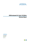
1
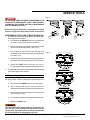
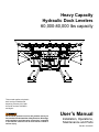
Heavy Capacity
Hydraulic Dock Levelers
60,000-80,000 lbs capacity
This manual applies to hydraulic
dock levelers manufactured
beginning February 2013 with
the serial numbers 61058683
and higher.
Do not install, operate or service this product unless you
have read and understand the Safety Practices, Warnings,
and Installation and Operating Instructions contained
in this manual. Failure to do so could result in death or
serious injury.
User’s Manual
Installation, Operations,
Maintenance and Parts
Part No. 6001947C
Contents
Introduction..................................................................2
Safety Signal Words....................................................2
Safety Practices..........................................................3
Owner's Responsibilities.............................................4
Ramp and Lip Grades.................................................5
Installation...................................................................6
Service Tools............................................................. 11
Components and Specifications................................ 12
Hydraulic System Operation......................................14
Operating Instructions...............................................15
Three Button Control..............................................15
One Button Control.................................................18
Planned Maintenance................................................21
Troubleshooting Guide..............................................24
Hydraulic Power Unit Adjustment.............................. 27
Hydraulic Schematic..................................................28
Electrical Schematics................................................32
Optional Auto Return to Dock (A.R.T.D.)
Operations..............................................................34
A.R.T.D. Proximity Switch Adjustment....................... 35
Parts List
Dock Leveler...........................................................36
Hydraulic and Electrical..........................................40
Control Panel..........................................................47
Warranty....................................................................53
Distributor Information...............................................54
Introduction
Welcome and thank you for choosing this dock leveler. This manual covers Serco® model HD and Kelley® model
HHC dock levelers. It is equipped with the patented HYDRA MAX® Lip Extension.
This User’s Manual contains information that you need to safely install, operate and maintain the dock leveler. It
also contains a complete parts list and information about ordering replacement parts. Please keep and read this
User’s Manual before using your new dock leveler.
Safety signal words
You may find safety signal words such as DANGER, WARNING, or CAUTION throughout this Owner’s Manual.
Their use is explained below:
This is the safety alert symbol. It is used
to alert you to potential personal injury
hazards. Obey all safety messages that
follow this symbol to avoid possible death or injury.
Indicates an imminently hazardous situation which, if
not avoided, will result in death or serious injury.
Indicates a potentially hazardous situation which,
if not avoided may result in minor or moderate
injury.
Indicates a potentially hazardous situation which,
if not avoided, could result in death or serious
injury.
Notice is used to address practices not related to
personal injury.
2
6001947C — Heavy Capacity Hydraulic Dock Levelers, 60-80K
©2013 4Front Engineered Solutions, Inc.
February 2013
Safety practices
OPERATION (continued)
Read these Safety Practices before installing, operating
or servicing the dock leveler. Failure to follow the Safety
Practices could result in death or serious injury.
If you do not understand the instructions, ask your supervisor
to explain them to you or contact your local authorized
distributor.
OPERATION
Use restricted to trained operators. Follow the procedures
on the placard posted near the dock leveler. Do not operate
the dock leveler with equipment, material or people on the
ramp or lip.
Do not use this unit to service vehicles outside its intended
working range which is 12" above and 12" below dock on 6'
and 8' long levelers, 15" above and 12" below dock on 10'
long levelers, and 16" above and 12" below dock on 12' long
levelers.
Do not operate the dock leveler when anyone is in front of it
unless they are securing the maintenance struts.
Stay clear of the dock leveler when it is moving.
KEEP HANDS CLEAR OF HINGES AT ALL TIMES. Do not
use hands to position dock leveler ramp or lip, or to store dock
leveler. Do not use the dock leveler if it appears damaged
or does not operate properly. Inform your supervisor
immediately. Do not stand in the driveway between the dock
leveler and the backing vehicle.
Chock vehicle wheels or lock vehicle into place with vehicle
restraining device and set brakes before loading or loading.
Before chocking wheels or engaging vehicle restraint, dump
air from air ride suspensions and set parking brake.
Ensure lip avoids contact with vehicle sides and cargo. If lip
does not lower to vehicle bed, reposition vehicle.
INSTALLATION, MAINTENANCE AND SERVICE
Place barricades on the dock floor around the dock leveler
pit and in the driveway in front of the pit while installing,
maintaining or repairing the dock.
Do not operate the dock leveler when anyone is standing
in front of the dock leveler unless they are securing the
maintenance struts.
Do not enter pit or do any maintenance or repair under
dock leveler unless leveler is securely supported by both
maintenance struts.
Disconnect the power and properly tag or lock out before
climbing into the pit or doing any maintenance or repair
under the leveler.
All electrical troubleshooting or repair must be done by a
qualified technician and must meet applicable codes.
Disconnect the power and properly tag or lock out before
doing any electrical work.
If it is necessary to make troubleshooting checks inside the
control box with the power on, USE EXTREME CAUTION!
Do not place fingers or uninsulated tools inside the control
box. Touching wires or other parts inside the control box
could result in electrical shock, death or serious injury.
Visually check that the lip is supported by the vehicle bed
or the lip is supported by both lip keepers before driving on
the ramp.
Store dock leveler to dock level with lip in both lip keepers
after use.
Move all equipment, material or people off the dock leveler
and store the dock leveler after use.
Do not use a forklift or other material handling equipment to
lower the ramp.
February 2013
6001947C — Heavy Capacity Hydraulic Dock Levelers, 60-80K
©2013 4Front Engineered Solutions, Inc.
3
Owner’s responsibilities
The owner’s responsibilities include the following:
The owner should recognize the inherent danger of the
interface between dock and transport vehicle. The owner
should, therefore, train and instruct operators in the safe use
of dock leveling devices.
When a transport vehicle is positioned as closely as practicable
to a dock leveling device, there shall be at least 4" of overlap
between the front edge of the lip and the edge of the floor or
still of the transport vehicle.
Nameplates, cautions, instructions and posted warnings
shall not be obscured from the view of operating or
maintenance personnel for whom such warnings are intended.
Manufacturer’s recommended periodic maintenance and
inspection procedures should be kept.
Dock leveling devices that are structurally damaged or
have experienced a sudden loss of support while under
load, such might occur when a transport vehicle is pulled
out from under the dock leveling device, shall be removed
from service, inspected by the manufacturer’s authorized
representative, and repaired as needed before being placed
back in service.
The owner shall see that all nameplates caution and
instruction markings or labels are in place and legible and
that the appropriate operating and maintenance manuals are
provided to users.
Modifications or alterations of dock leveling devices
shall be made only with written permission of the original
manufacturer.
When industrial vehicles are driven on and off transport
vehicles during the loading and unloading operation, the
brakes on the transport vehicle shall be applied and wheel
chocks or positive restraints that provide the equivalent of
wheel chocks engaged.
The dock leveler should never be used outside the
manufacturer’s labeled rated capacity. It must also be
compatible with the loading equipment and other conditions
relating to the dock.
4
6001947C — Heavy Capacity Hydraulic Dock Levelers, 60-80K
©2013 4Front Engineered Solutions, Inc.
February 2013
Ramp and lip grades
Fig. 1
Leveler grade
Lip grade
-------
-------
-------
-------
--8.1
7.6
--4.4
3.9
7.1
6.7
6.3
3.5
3.1
2.7
12.0
10.0
8.0
10.9
9.4
7.8
7.3
5.8
4.2
8.3
7.1
5.9
4.7
3.5
2.3
6.6
5.7
4.7
3.0
2.1
1.1
5.5
4.8
4.0
1.9
1.2
0.4
6.0
4.0
2.0
6.3
4.7
3.2
2.7
1.1
-0.4
4.7
3.6
2.4
1.1
0.0
-1.2
3.8
2.9
1.9
0.2
-0.7
-1.7
3.2
2.4
1.6
-0.4
-1.2
-2.0
0.0
-2.0
-4.0
-6.0
1.6
0.1
-1.4
-3.0
-2.0
-3.5
-5.0
-6.6
1.2
0.1
-1.1
-2.3
-2.4
-3.5
-4.7
-5.9
1.0
0.1
-0.9
-1.8
-2.6
-3.5
-4.5
-5.4
0.8
0.1
-0.7
-1.5
-2.8
-3.5
-4.3
-5.4
-8.0
-10.0
-12.0
-4.5
-6.1
-7.6
-8.1
-9.7
-11.2
-3.4
-4.6
-5.8
-7.0
-8.2
-9.4
-2.8
-3.7
-4.6
-6.4
-7.3
-8.2
-2.3
-3.1
-3.9
-5.9
-6.7
-7.5
Leveler and lip grades minimum bend, 18" lip.
February 2013
Above dock
Above dock
Below dock
16.0
15.0
14.0
Leveler and lip grades,
Vehicle bed
% for each dock leveler length
position
6'
Leveler
8' Leveler 10' Leveler 12' Leveler
from dock,
(in.)
Leveler Lip Leveler Lip Leveler Lip Leveler Lip
Below dock
Leveler and lip grades,
Vehicle bed
% for each dock leveler length
position
6'
Leveler
8' Leveler 10' Leveler 12' Leveler
from dock,
(in.)
Leveler Lip Leveler Lip Leveler Lip Leveler Lip
16.0
15.0
14.0
-------
-------
-------
-------
--8.6
8.2
--1.4
1.0
7.6
7.2
6.8
0.4
0.0
-0.4
12.0
10.0
8.0
11.8
10.3
8.7
4.6
3.1
1.5
8.9
7.7
6.6
1.7
0.5
-0.6
7.2
6.2
5.3
0.0
-1.0
-1.9
6.0
5.2
4.4
-1.2
-2.0
-2.8
6.0
4.0
2.0
7.2
5.6
4.1
0.0
-1.6
-3.1
5.4
4.2
3.1
-1.8
-3.0
-4.1
4.3
3.4
2.5
-2.9
-3.8
-4.7
3.6
2.9
2.1
-3.6
-4.4
-5.1
0.0
-2.0
-4.0
-6.0
2.5
-1.0
-0.6
-2.1
-4.7
-6.2
-7.8
-9.3
1.9
0.7
-0.4
-1.6
-5.3
-6.5
-7.6
-8.8
1.5
0.6
-0.4
-1.3
-5.7
-6.6
-7.6
-8.5
1.3
0.5
-0.3
-1.1
-6.0
-6.7
-7.5
-8.3
-8.0
-10.0
-12.0
-3.7
-5.2
-6.8
-10.9
-12.4
-14.0
-2.8
-3.9
-5.1
-10.0
-11.1
-12.3
-2.2
-3.2
-4.1
-9.4
-10.4
-11.3
-1.9
-2.7
-3.4
-9.1
-9.9
-10.6
Leveler and lip grades maximum bend, 18" lip.
6001947C — Heavy Capacity Hydraulic Dock Levelers, 60-80K
©2013 4Front Engineered Solutions, Inc.
5
Installation
PIT CHECK
1. Check entire dock leveler pit for proper construction
according to certified pit drawings. Check electrical service
to assure it agrees with the phase and voltage of the
hydraulic power unit and control panel supplied with the
dock leveler. See tag attached to motor, and the wiring
diagram located inside the control panel.
leveler CHECK prior to installation
1. Visually check that all rear hinge pins, cotter pins, and
kliprings are in place.
Fig. 2
48"
Push-button
control panel
May be different depending
on owner’s requirement
2. Visually check that the lip pin retainers are in place on
both ends of the lip rod.
3. Visually check that both the maintenance bar and both
maintenance struts are undamaged and pins securely
attached.
Installation of dock leveler
Place barricades around pit on dock floor and drive
while installing, maintaining or repairing dock leveler.
Power to control box must be from fused disconnect
supplied by others. Fuse size for a time delay type
fuse can be no greater than 225% of motor FLA. Before
doing any electrical work, make certain the power is
disconnected and properly tagged or locked out. All
electrical work must be done by a qualified technician
and must meet all applicable codes. If it is necessary to
make troubleshooting checks inside the control panel
with the power on, USE EXTREME CAUTION. Do not
place fingers or uninsulated tools inside the control
panel. Touching wires or other parts inside the control
panel could cause electrical shock, death or serious
injury.
1. Mount and wire control panel. See wiring diagram located
inside the control panel and wiring diagrams in this manual.
See Fig. 2.
2. 4" × 4" shims are to be placed under each of the rear
upright supports, under the hydraulic cylinder mount(s),
under both of the front lip keepers and both maintenance
struts and behind the rear frame to the back of the pit wall.
See Fig. 4.
6
6001947C — Heavy Capacity Hydraulic Dock Levelers, 60-80K
©2013 4Front Engineered Solutions, Inc.
February 2013
Installation, continued
3. Stack shims so the dimension from the top of the shims
to the top of the dock floor is 23" at the back of the pit
and 23-1/2" at the front of the pit. See Fig. 5.
Before installing the dock leveler, read and follow the
Safety Practices on page 3. Failure to follow the safety
practices could result in death or serious injury.
Fig. 4
Shim to the back of pit wall
60,000 lbs. capacity
4. Remove shims from pit and weld in place on the bottom
of the dock leveler frame under the corresponding upright
support. Weld shims needed behind the rear frame to
contact the back pit wall using 1" welds. See Fig. 4.
5. Screw in two 3/4"-10 load centering eye bolts into the
top of the top plate. Place a chain or other suitable lifting
device through the eye bolts. The dock leveler should not
be lifted in any other manner when placed into the pit.
See Fig. 6.
Inadequate lifting equipment or practices can cause a
load to fall unexpectedly. Make sure the lifting chain or
other lifting devices are in good condition and have a
rated capacity of at least 3500 lbs for the lifting angle
used. Never allow anyone to stand on or near the dock
leveler when it is lifted or placed into the pit. Stand clear
of the dock leveler when it is placed into the pit. Failure
to follow this warning can allow the dock leveler to
fall, tip, or swing into people, causing death or serious
injury.
80,000 lbs. capacity
Fig. 5
Dock floor
Rear pit
curb angle
23" to string line
6. Place the dock leveler into the pit. Leave room between
the rear of the dock leveler frame and the rear of the pit
so that electrical wires can be connected.
7. Connect the electrical wiring to the dock leveler junction
box. See Fig. 3 and applicable wiring schematic.
Pit floor
4"
Fig. 6
3/4"-10
load centering
eye-bolts
February 2013
6001947C — Heavy Capacity Hydraulic Dock Levelers, 60-80K
©2013 4Front Engineered Solutions, Inc.
7
Installation, continued
8. Move the dock leveler back to the rear pit angle. With the
rear leveler angle touching the rear pit angle, square up
the sides of the pit to the sides of the leveler. The gap
should be even on both sides. See Fig. 7.
Fig. 7
1/2"
NOTE:
If the pit is out-of-square, the resulting gap between the
rear frame and the rear curb angle should be shimmed as
necessary at the weld locations. Use steel shim(s) equal to
the weld length and weld in place.
Rear
frame
angle
Rear pit
curb angle
1/2"
Ramp
Pit side curb angle
Route power cord clear of edges and resting surfaces
so that it is not damaged during lifting and placement.
9. Shim the front end of the leveler per Fig. 8 so it is level
with dock floor.
10. Check to confirm that the shimmed height of the rear of the
dock leveler frame is proper for a smooth transition from the
dock to the dock leveler. Add or remove shims as required.
Fig. 7A
The rear edge of the dock leveler should be level or
slightly (1/16" maximum) below dock level.
Shim the front end of the dock leveler LEVEL with the
dock floor. See Fig. 8 and 9. Add or remove shims as
required.
Weld
4" x 4" shim
11. Check the alignment of the dock leveler with the sides of
the pit. See Fig. 7.
Welding with the dock leveler’s power connected can
damage electrical components. If the dock leveler has
previously been electrically connected, turn off power
to control box. Ground welder to dock leveler frame.
Failure to do so can result in product damage.
Be certain that the rear frame angle is held tightly against
the rear pit curb angle before welding.
If front and rear pit curb angles are not parallel do not
attempt to shim dock leveler supports to match pit
angles. The front supports and rear frame angle must
be parallel for proper operation of the dock leveler. Add
or subtract shims as required.
12. Weld rear frame angle to the rear pit curb angle. See Fig.
8.
8
6001947C — Heavy Capacity Hydraulic Dock Levelers, 60-80K
©2013 4Front Engineered Solutions, Inc.
February 2013
installation, continued
NOTE:
If the pit width conforms to the certified pit drawing, there
will be a 1/2" gap between the ends of the frame at the rear
hinge assembly and the side curb angles. If this is not the
case, the dock leveler will have to be positioned as required to
accommodate dimensional discrepancies and any additional
considerations (e.g. conduit runs, etc.).
13.Weld front frame to shims, and shims to front curb angle
with a minimum of 3" long 1/4" fillet welds on the front
and sides.
14.Remove shipping banding holding lip assembly closed.
Discard banding.
Fig. 8
Shim under
rear hinge
posts
(Shims –
4" x 4"
x height)
16.Two people are needed to place the dock leveler on the
maintenance strut.
a. One person must hold dock leveler in its highest
position with electrical controls or other lifting
device.
Level
with
floor
Gap
1/2" - 1"
Gap
1/2" - 1"
Level
with
floor
at this
area
15.If electrical power is available, use the electrical controls
to raise the ramp and lip to their full above dock position.
See operating instructions in this manual. If electrical
power is not available, use a chain and load centering
eyebolt.
Hydraulic pressure must be maintained on the ramp to
hold it in the raised position until the maintenance strut
is in place. DO NOT WORK UNDER THE DOCK LEVELER
RAMP OR LIP UNLESS BOTH Maintenance strutS
ARE SECURELY SUPPORTING THE DOCK LEVELER.
Weld rear frame at
1/4" bevel locations
Door
contact
area
Shim under both subframe tubes. Shim
behind lip keepers if keepers project below
pit floor, and weld to front face of curb
angle. Shim under both maintenance struts.
See Fig. 4 for all weld locations.
(Shims – 4" x 4" x height)
NOTE:
Shim under both subframe tubes. Shim behind lip keepers if
keepers project below pit floor, and weld to front face of curb
angle. Shim under both maintenance struts. See Fig. 4 for
all weld locations.
Fig. 9
Improper installation
b. The second person positions the maintenance struts
into their upright position. See Fig. 13.
c. Electrical controls may now be released.
17.Remove shipping cotter pins from telescopic toe guards
(if equipped). See Fig. 10.
Proper installation
February 2013
6001947C — Heavy Capacity Hydraulic Dock Levelers, 60-80K
©2013 4Front Engineered Solutions, Inc.
9
Installation, continued
Fig. 10
Welding with dock leveler’s power connected can
damage electrical components. If the dock leveler has
previously been electrically connected, turn off power
to control box. Ground welder to dock leveler frame.
Failure to do so could result in product damage.
18. Install shims under both ramp cylinder mounting pads to
provide solid support to concrete. Weld shims together
and to lower cylinder mounting pad(s) using 1" long 1/4"
fillet welds on three sides. See Fig. 7A.
Remove
shipping cotter
pins
19. Remove lifting chain or other lifting devices.
20.Read Safety Practices on page 3 and Operating
instruction on pages 15-20.
21. Connect electrical wiring and turn on power to dock
leveler control panel. See Fig. 3.
22. Two people are needed to store the maintenance
struts.
a. Press raise button on the control panel and hold.
b. The second person lowers both maintenance
struts.
c. First person can now release raise button and
leveler will float down.
Keep hands, fingers and head away from the lip when
the raise button is released. The lip and dock leveler
are free to move downward when hydraulic pressure is
removed from cylinders.
Fig. 11
3/8" side of pit to
side of bumper
mounting plate
Full length
of bumper
mounting plate.
Downhill welds are
not acceptable.
Vertical bumper
mounting angle
Laminated Bumper
Fig. 12
Warning and
operating
instruction
placard
23. Mount dock bumpers to face of dock. Downhill welds are
not acceptable. See Fig. 11.
24. Permanently mount the laminated dock leveler warning
and operating placard on the wall near the dock leveler
controls. See Fig. 12. Make sure the customer gets the
User's Manual and is properly trained.
3/4" dia. anchor
bolt, field
installed,
supplied
by others
1/4"
48"
25. Operate the dock leveler four times through the complete
cycle to check operation. Read Safety Practices on page
3 and Operating Instructions on pages 15-20.
26. Check hydraulic fluid level. Reference page 27.
10 6001947C — Heavy Capacity Hydraulic Dock Levelers, 60-80K
©2013 4Front Engineered Solutions, Inc.
February 2013
Service tools
Fig. 13
DO NOT WORK UNDER THE DOCK LEVELER RAMP OR LIP
UNLESS BOTH Maintenance strutS ARE SECURELY
SUPPORTING THE LEVELER, AND THE LIP Maintenance
BAR IS SUPPORTING THE LIP.
Before servicing the dock leveler, read and follow the Safety
Practices on page 3 and the operation section of this manual.
Maintenance strutS and LIP Maintenance BAR
1. To raise both maintenance struts and the lip maintenance
bar two people are needed:
a. Push and hold the raise button on the control panel
so leveler is fully raised and lip is extended.
1
2
3
b. The second person raises the maintenance struts
into the locked vertical position. See Fig. 13.
c. Pull out hitch pin and clevis pin from top hole of lip
maintenance bar bracket and raise lip maintenance
bar. See Fig. 14.
Fig. 14
d. Reinsert clevis pin through brackets and lip maintenance
bar bracket. Then reinsert the hitch pin into the clevis pin.
e. Release the raise button and leveler will lower to
securely supported position resting on both maintenance struts.
2. To lower both maintenance struts from their locked upright
position two people are needed:
NOTE:
Avoid pressing the RAISE button with lip maintenance bar in
the raised position, as this can damage the lip maintenance bar.
a. Push and hold the raise button on the control panel.
b. Pull out hitch pin and clevis pin from top hole on lip
maintenance bar bracket and lower lip maintenance bar.
c. Reinsert clevis pin through brackets and then put hitch
pin in clevis pin to store.
d. Lift up and then push back to lower both maintenance struts.
e. Release the raise button.
It is important to always engage the lip maintenance bar
lock pin when ever working under the leveler with the
lip extended. Any upward force on the lip could release
the lip maintenance bar allowing the lip to fall.
February 2013
6001947C — Heavy Capacity Hydraulic Dock Levelers, 60-80K
©2013 4Front Engineered Solutions, Inc.
11
Components and specifications
The main components of the dock leveler are shown below.
See the Parts List for specific part numbers.
Fig. 15 (80K leveler shown)
Lip plate
ARTD sensor
(optional)
Lip hinge
Lip
maintenance
bar
Lip cylinder
Leveler stored switch
mounting bracket
(optional)
Safety stop (velocity fuse)
Top plate
Hydraulic power unit
Maintenance strut
Lip keepers/
ramp stops
12 Main lift cylinders
Maintenance strut
Frame
6001947C — Heavy Capacity Hydraulic Dock Levelers, 60-80K
©2013 4Front Engineered Solutions, Inc.
February 2013
Components and specifications, continued
Fig. 16
Fig. 17
RAISE
button
RAISE
button
LIP EXTEND
button
1-button unit
STOP
button
3-button unit
Control Panel - NEMA 4 (plastic enclosure), automatic motor
starter, thermal overload, 0.5A resettable control circuit
breaker. UL or cUL approved.
Auto Return to Dock Proximity Switch - NEMA 6P, normally
open, with LED pilot light.
Motor - NEMA Standard T.E.N.V. / 48YZ frame, 1 h.p., single
or three phase or 24V DC.
Hydraulic Fluid - An all weather hydraulic fluid with a
viscosity of 15 CSt at 40°C (100°F), such as:
Shell Tellus T 15
Mobil Aero HFA (49011)
Exxon Univis: HV13, N15, J13
Texaco Aircraft Oil #1554
U.S. Oil Co., Inc #ZFI-5606 (Low Temp.)
Pump - Fixed displacement gear pump, 2 gpm, primary relief
valve factory set at 1400 psi.
February 2013
6001947C — Heavy Capacity Hydraulic Dock Levelers, 60-80K
©2013 4Front Engineered Solutions, Inc.
13
Hydraulic system operation
Fig. 18
The following describes the operation of the hydraulic
system when the control is activated:
RAISE
• Pump starts
• Main lift cylinder extends and lip cylinder retracts
Fully Raised
•Pressure increases
•Sequence valve shifts
•Lip cylinder extends
Stop Raise
•Sequence valve resets
•Deck floats down forcing fluid to reservoir
•Float speed controlled by flow control needle valve
LIP EXTEND
•With leveler above dock height, pump starts as above
•Solenoid valve shifts locking main cylinder in partial
raised position
•Pressure increases, sequence valve shifts and lip
extends
STOP
• Solenoid valve shifts, stopping main cylinder and lip
cylinder
•Power cut off from motor control circuit
3-button unit
Fig. 19
1-button unit
14 RAISE
• Pump starts and shuttle valve shifts
• Main lift cylinder extends and lip cylinder retracts
• Pilot check valve opens.
Fully Raised
• Pressure increases
• Sequence valve shifts
• Lip cylinder extends.
Stop Raise
• Sequence valve and shuttle valve return
• Top plate floats down forcing fluid to reservoir
• Float speed controlled by flow control in shuttle valve.
6001947C — Heavy Capacity Hydraulic Dock Levelers, 60-80K
©2013 4Front Engineered Solutions, Inc.
February 2013
Operating instructions
3-Button Controls
INTRODUCTION
Before operating the dock leveler, read and follow the
Safety Practices on page 3.
Use by untrained people can result in death or serious
injury. Read and follow complete operating instructions.
DO NOT USE DOCK LEVELER IF IT APPEARS
DAMAGED, OR DOES NOT SEEM TO WORK PROPERLY.
Inform your supervisor immediately.
Always be certain that the vehicle wheels are chocked , or
that the vehicle is locked in place by a vehicle restraining
device and the brakes set before loading or unloading.
Visually inspect vehicle restraint to make sure it is
properly engaged. Vehicles pulling away unexpectedly
can cause uncontrolled drop of the dock leveler which
can result in death or serious injury. The maximum
uncontrolled drop of this hydraulic dock leveler from
any position is 4 inches.
Visually check that the lip is supported by the vehicle
bed or the ramp is supported by both front lip keepers
before driving or walking on the ramp.
Always return the dock leveler to its dock level (stored)
position before allowing the vehicle to leave the dock.
If the vehicle pulls away before the dock leveler is
stored, the lip will fall to its pendant position and may
not be supported by the lip keepers. In addition, failure
to properly store the dock leveler may leave the leveler
in a position below the level of the dock floor. These
conditions may result in unexpected drop of personnel
or material handling equipment and result in death or
serious injury.
This dock leveler is designed to span and compensate for
space and height differences between a loading dock and
freight carrier to allow safe, efficient freight transfers.
The Hydraulic Dock Leveler with Three Button Control has
a stop button control to stop downward movement of the
ramp and shuts off the raise and lip extend push-button
controls. A valve will not allow the ramp to lower. The stop
button must be out during normal use.
Pushing and holding the raise push-button operates a
hydraulic cylinder to raise the ramp. Releasing the raise
push-button allows the ramp to lower.
When the dock leveler reaches its full raised position, a
second hydraulic cylinder extends the dock leveler lip. The
dock leveler with its lip extended settles onto the vehicle
bed forming a bridge.
After loading, pushing and holding the raise push-button
raises the ramp, and the extended lip lowers to its stored
position. Releasing the raise push-button allows the dock
leveler to lower to its level, stored position.
With the dock leveler in its stored position, lip keepers
support the dock leveler ramp at a position level with the
dock floor.
The Hydraulic Dock Leveler with Three Button Control also
has a lip extend push-button control to extend the dock
leveler lip before the ramp reaches its full raised position.
Releasing the LIP extend push-button allows the ramp
to lower.
Before pressing button, ensure lip avoids contact with
vehicle sides and cargo. If lip does not lower to vehicle
platform, reposition the vehicle.
Before chocking wheels or engaging vehicle restraint,
dump air from air ride suspensions and set parking
brakes.
Never drive on dock leveler with STOP button pressed in.
Failure to follow these instructions could result in death
or serious injury to operators and/or bystanders.
February 2013
6001947C — Heavy Capacity Hydraulic Dock Levelers, 60-80K
©2013 4Front Engineered Solutions, Inc.
15
Operating instructions, continued
3-Button Controls
3-button unit
Always secure the vehicle with a vehicle restraint or
wheel chocks before operating the dock leveler.
Do not operate dock leveler with anyone standing on or
in front of it.
Before allowing vehicle to leave always return the dock
leveler to its dock level (stored) position with the lip
stored in both lip keepers. See Fig. 23. Failure to do so
may leave the dock leveler in a position below the level of
the dock floor. This condition may result in unexpected
drop of personnel or material handling equipment and
could result in death or serious injury.
Do not drive on dock leveler or lip until it is fully extended
and supported by the vehicle's platform.
Always keep hands and feet clear of all moving parts.
Always restore the leveler to its safe dock level position
after servicing the vehicle.
Fig. 20
Press to raise
Do not drive on leveler with STOP button pressed in.
Never use fork lift or other material handling equipment
to lower the ramp and lip sections.
Raise
If equipped with Auto Return to Dock the dock leveler
will automatically raise and return to dock level when
the lip starts to retract.
Raising Leveler
1. Press the RAISE button on the control panel to raise the
leveler. See Fig. 19.
2. When the leveler is fully raised, the lip will automatically
extend. To extend earlier, press the LIP EXTEND button.
See Fig. 20.
3. When lip is fully extended release the RAISE button. The
leveler will slowly float down to the vehicle's platform.
Push the STOP button at any time to stop the leveler.
Pull the STOP button to release. See Fig. 22.
Fig. 21
Press to extend
Lip extend
NOTE:
If an obstruction prevents the lip from deploying properly,
push the STOP button. Press the RAISE button to raise
and retract the lip. Restore the leveler to the safe dock level
position with the lip in both lip keepers for endloading.
16 6001947C — Heavy Capacity Hydraulic Dock Levelers, 60-80K
©2013 4Front Engineered Solutions, Inc.
February 2013
Operating instructions, continued
3-Button Controls
3-button unit, continued
Fig. 22
Release to lower
Storing Leveler
1. To return the leveler to the stored position, press the
RAISE button. As the leveler raises the lip will retract.
When the lip is fully retracted, release the RAISE button.
The leveler will float down to the stored position. See Fig.
23.
Below-Dock Endloading
1. Press the RAISE button until leveler is about 6" above
dock. Press the LIP EXTEND button until the lip has
extended 2 to 3 inches to clear the front of the keepers
and release the button. Leveler will float down for
endloading. See Fig. 24.
Float down
Fig. 23
Press to raise
Release to lower
Fig. 24
Press to raise
Press to extend lip
Auto-return-to-dock (a.r.t.d optional)
The A.R.T.D. automatically resets the leveler whenever a
vehicle just pulls away from the loading dock with the lip
resting on the vehicle.
1. If the vehicle pulls away, the leveler will float down to
the lowest position and the lip will fall. The leveler will
automatically raise, retract the lip, then float down to the
stored position. See Fig. 25.
Lip extend
Float down
Fig. 25
February 2013
6001947C — Heavy Capacity Hydraulic Dock Levelers, 60-80K
©2013 4Front Engineered Solutions, Inc.
17
Operating instructions
1-Button Control
INTRODUCTION
Before operating the dock leveler, read and follow the
Safety Practices on page 3.
Use by untrained people can result in death or
serious injury. Read and follow complete operating
instructions.
DO NOT USE DOCK LEVELER IF IT APPEARS
DAMAGED, OR DOES NOT SEEM TO WORK PROPERLY.
Inform your supervisor immediately.
Always be certain that the vehicle wheels are chocked , or
that the vehicle is locked in place by a vehicle restraining
device and the brakes set before loading or unloading.
Visually inspect vehicle restraint to make sure it is
properly engaged. Vehicles pulling away unexpectedly
can cause uncontrolled drop of the dock leveler which
can result in death or serious injury. The maximum
uncontrolled drop of this hydraulic dock leveler from
any position is 4 inches.
This dock leveler is designed to span and compensate for
space and height differences between a loading dock and
freight carrier to allow safe, efficient freight transfers.
This dock leveler uses a push-button control to position the
ramp. Pushing and holding the raise button operates a
hydraulic cylinder(s) to raise the ramp. Releasing the raise
button allows the ramp to lower.
When the dock leveler reaches its full raised position, a
second hydraulic cylinder(s) extends the dock leveler lip. The
dock leveler with its lip extended settles onto the vehicle bed
forming a bridge.
After loading pressing and holding the raise button allows
the ramp to raise. The lip will retract as the dock leveler is
raised. Releasing the raise button lowers the ramp into its
level, stored position.
With the dock leveler in its stored position, lip keepers support
the dock leveler ramp at a position level with the dock floor.
Visually check that the lip is supported by the vehicle
bed or the ramp is supported by both front lip keepers
before driving or walking on the ramp.
Always return the dock leveler to its dock level (stored)
position before allowing the vehicle to leave the dock.
If the vehicle pulls away before the dock leveler is
stored, the lip will fall to its pendant position and may
not be supported by the lip keepers. In addition, failure
to properly store the dock leveler may leave the leveler
in a position below the level of the dock floor. These
conditions may result in unexpected drop of personnel
or material handling equipment and result in death or
serious injury.
Before pressing button, ensure lip avoids contact with
vehicle sides and cargo. If lip does not lower to vehicle
platform, reposition the vehicle.
Before chocking wheels or engaging vehicle restraint,
dump air from air ride suspensions and set parking
brakes.
18 6001947C — Heavy Capacity Hydraulic Dock Levelers, 60-80K
©2013 4Front Engineered Solutions, Inc.
February 2013
Operating instructions, continued
1-Button Control
1-button unit
Fig. 26
Press to raise
Always secure the vehicle with a vehicle restraint or
wheel chocks before operating the dock leveler.
Do not operate dock leveler with anyone standing on or
in front of it.
Raise
Do not drive on dock leveler or lip until it is fully extended
and supported by the vehicle's platform.
Always keep hands and feet clear of all moving parts.
Always restore the leveler to its safe dock level position
after servicing the vehicle.
Never use fork lift or other material handling equipment
to lower the ramp and lip sections.
Fig. 27
Press to extend
Lip extend
If equipped with Auto Return to Dock the dock leveler
will automatically raise and return to dock level when
the lip starts to retract.
Raising Leveler
1. Press the RAISE button on the control panel to raise the
leveler.
2. Continue to press the RAISE button. The lip will
automatically extend when the leveler is fully raised.
3. When lip is fully extended release the RAISE button. The
leveler will slowly float down to the vehicle's platform.
NOTE:
If an obstruction prevents the lip from deploying properly,
press the button to raise and retract the lip. Restore the
leveler to the safe dock level position with the lip in both lip
keepers for endloading.
Before allowing vehicle to leave always return the
dock leveler to its dock level (stored) position with the
lip stored in both lip keepers. See Fig. 26. Failure to
do so may leave the dock leveler in a position below
the level of the dock floor. This condition may result
in unexpected drop of personnel or material handling
equipment and could result in death or serious injury.
February 2013
6001947C — Heavy Capacity Hydraulic Dock Levelers, 60-80K
©2013 4Front Engineered Solutions, Inc.
19
Operating instructions, continued
1-Button Control
1-button unit, continued
Fig. 28
Release to Lower
Before allowing vehicle to leave always return the dock
leveler to its dock level (stored) position with the lip
stored in both lip keepers. See Fig. 29. Failure to do so
may leave the dock leveler in a position below the level
of the dock floor. This condition may result in unexpected
drop of personnel or material handling equipment and
could result in death or serious injury.
Float down
Storing Leveler
1.To return the leveler to the stored position, press the
RAISE button. As the leveler raises the lip will retract.
When the lip is fully retracted, release the RAISE button.
The leveler will float down to the stored position. See Fig.
28.
Fig. 29
Press to raise
Release to lower
Below-Dock Endloading
1.Press the RAISE button until leveler is fully raised and
the lip starts to extend. When the lip has extended 2 to
3 inches to clear the front of the keepers, release the
RAISE button. Leveler will float down for endloading.
See Fig. 30.
Auto-return-to-dock (a.r.t.d optional)
The A.R.T.D. automatically resets the leveler whenever a
vehicle just pulls away from the loading dock with the lip
resting on the vehicle. This is how it works.
1.If the vehicle pulls away, the leveler will float down to
the lowest position and the lip will fall. The leveler will
automatically raise, retract the lip, then float down to the
stored position. See Fig. 31.
Fig. 30
Press to raise
and extend Lip
Lip extend
Float down
Fig. 31
20 6001947C — Heavy Capacity Hydraulic Dock Levelers, 60-80K
©2013 4Front Engineered Solutions, Inc.
February 2013
Planned Maintenance
To ensure the proper operation of your dock leveler, perform
the following planned maintenance procedures.
quarterly
Be certain before climbing into the dock leveler pit or
doing any maintenance or repair under the dock leveler,
that:
1) THE MAINTENANCE STRUT IS SECURELY
SUPPORTING THE LEVELER (see page 13-14).
2) The power is disconnected and properly tagged or
locked out.
2.Clean out the inside of the pit area. If washing out, take
care not to spray any electrical parts.
Before servicing the dock leveler, read and follow the
Safety Practices on page 3 and the operation section of
this manual.
Place barricades on the dock floor around the dock
leveler pit and in the driveway in front of the pit while
installing, maintaining or repairing the dock leveler.
WEEKLY
1.Inspect all warning labels and placards. See page 23.
Replace as necessary.
3.Inspect and lubricate all mechanical pivot points on
the leveler with S.A.E. 30 oil. Cycle the leveler when
lubricating.
4.Inspect the hydraulic cylinders and hoses for any fluid
loss and check the reservoir level. Add fluid as required.
See Hydraulic Fluid Level on page 27.
5.Inspect all welds under the leveler for fatigue or failure,
particularly the lip plate hinge and top plate beams and
front hinge bar. If cracks are discovered, contact your
authorized Serco distributor.
6.Check the full operation of the leveler. Make any
adjustments required.
1.Clean the upper portion of the lip plate hinge with a brush
and blow away all dirt and debris. This will ensure proper
lip plate operation.
7.Lubricate the lip hinge tubes with a molybdenum disulfide
NLGI #2 grease. Do not over grease. Stop when grease
begins to ooze out of the hinge tube ends. Wipe off excess
grease.
2.Inspect for debris in rear hinge area of the leveler and
between the sides and curb angles to ensure smooth
operation. Clean as required.
8. Inspect dock bumpers. Six inches (6") of bumper
protection is required. Worn, torn, loose or missing
bumpers must be replaced.
3.Check the full operation of the leveler to ensure there is
no hesitation in the hydraulic system. Any loss of fluid
will affect the safety valve operation.
4.Inspect the operation of the telescopic toe guards to
ensure they are not distorted or binding when the leveler
is operating.
5.Clean away any debris from the rear hinge area of the
leveler and between the sides and curb angles to ensure
smooth operation.
February 2013
6001947C — Heavy Capacity Hydraulic Dock Levelers, 60-80K
©2013 4Front Engineered Solutions, Inc.
21
Planned Maintenance, continued
Hydraulic Fluid - An all weather hydraulic fluid with a
viscosity of 15 CSt at 40°C (100°F), such as:
Legend
Symbol
Shell Tellus T 15
Mobil Aero HFA (49011)
Exxon Univis: HV13, N15, J13
Texaco Aircraft Oil #1554
U.S. Oil Co.,Inc #ZFI-5606 (Low Temp.)
Description
Lubricate - oil
Light oil - SAE 30
Lubricate - grease
Molybdenum disulfide
NLGI #2
Cleaning
(Location - frequency)
Fig. 32
Visually Inspect
(Replace damaged or worn)
Rear hinge pins 5 places
Pins
Hoses
Pit - quarterly
22 6001947C — Heavy Capacity Hydraulic Dock Levelers, 60-80K
©2013 4Front Engineered Solutions, Inc.
February 2013
Planned Maintenance, continued
Every 90 days (quarterly) inspect all safety labels and
tags to ensure they are on the dock leveler and are easily
legible. If any are missing or require replacement, please
call 1-800-525-2010 or 972-466-0707 for replacements.
Fig. 33
6008485 (x2)
138-837 (x2)
Locate at
middle of leveler
921-075
(note: labels on
reservoir should
face center of leveler)
Optional
ARTD Only
921-074 (x2)
921-070
(x2)
OPERATIONS
921-051
921-026
921-050
921-027
6004906
(3-Button)
921-023
921-052
921-053
OPERATIONS
6004905
(1-Button)
921-054
921-147
February 2013
WARNING AND OPERATION PLACARD
(MOUNTED ON WALL NEAR LEVELER)
6001947C — Heavy Capacity Hydraulic Dock Levelers, 60-80K
©2013 4Front Engineered Solutions, Inc.
23
Troubleshooting guide
Use the Troubleshooting Guide if ever the leveler fails
to perform properly. Find the condition that most closely
matches your situation and make the recommended
adjustments. Observe all safety warnings before attempting
any maintenance procedure.
PROBLEM
1. Leveler does not raise. Motor is
silent.
2. Leveler does not raise; motor
starts then stops, motor starter
relay chatters.
3. Leveler does not raise. Motor
hums.
4. Leveler does not raise. Motor
runs.
24 Before servicing the dock leveler, read and follow the
Safety Practices on Page 3 and the Operation section in
this manual.
POSSIBLE CAUSE
SOLUTION
a) No electrical power to control panel.
a) Check that voltage is present at
terminal connections to the control
panel.
b) Electrical connections incorrect or
broken.
b) Check that wiring matches the wiring
diagram.
a) Overload relay, main circuit breaker
or leveler control circuit breaker
tripping.
a) Verify overload relay is set to approx.
15% above FLA indicated on motor
nameplate.
b) Voltage drop due to undersized
wiring run a long distance from the
power source.
b) Check voltage when motor is started.
Voltage drop is more often a problem
on single phase motors. Verify the
power supply wiring to the control panel
is sized correctly.
a) Voltage drop.
a) Measure voltage when motor is started.
Voltage drop is more often a problem
on single phase motors. Verify the
power supply wiring to the control panel
is sized correctly.
b) Loss of 1 phase. (Three phase
only.)
b) Measure for voltage at all three motor
connections (T1, T2, T3) in control panel.
a) Low fluid level in reservoir.
a) The hydraulic fluid level should be
checked when the leveler is resting
on the maintenance strut with the lip
pendant. Add fluid if required and check
for leaks. See page 27, Fig. 35.
b) Pump not running or pressure
insufficient.
b) Remove the hose from main lift cylinder
and point free end into reservoir opening.
If no oil is pumped, replace pump.
c) Pump running in reverse.
c) Check motor rotation and change
electrical connections if necessary. See
motor name plate.
d) Primary relief valve setting too low.
d) Set primary relief valve setting to 1400
PSI. See page 26-27. Note: Requires
use of pressure gauge or pump will be
severely damaged.
6001947C — Heavy Capacity Hydraulic Dock Levelers, 60-80K
©2013 4Front Engineered Solutions, Inc.
February 2013
Troubleshooting guide, continued
Before servicing the dock leveler, read and follow the
Safety Practices on Page 3 and the Operation section in
this manual.
PROBLEM
5. Overload relay tripping.
POSSIBLE CAUSE
SOLUTION
a) Overload relay set too low.
a) Check motor full load amperage and
overload relay setting.
b) Loss of one phase. (Three phase
only.)
b) Check for voltage at all three motor
connections (T1,T2,T3) in control
panel.
6. Leveler will not lower.
a) Automatic safety stop (velocity fuse)
is locked.
a) If a load was on the leveler, remove
the load and jog the RAISE button to
unlock the leveler. If no load was on
the leveler, adjust the needle valve to
reduce drop speed. See page 26-27.
7. Leveler floats down too slowly.
a) Flow control requires adjustment.
a) Adjust flow needle valve for faster flow.
Turn counterclockwise to increase
speed. See page 26-27.
8. Lip plate will not extend, or
extends too slowly.
a) Low fluid level in reservoir.
a) Check fluid level. Add fluid if required
and check for leaks. See page 27, Fig.
35.
b) Sequence valve set too high.
b) Decrease sequence valve setting. See
page 26-27.
c) Lip hinge binding.
c) Inspect hinge area for damage or
trapped debris. Lubricate hinge.
d) Primary relief valve set too low.
d) Set primary relief valve to 1400 PSI.
See page 26-27. Note: Requires use
of pressure gauge or pump will be
severely damaged.
a) Sequence valve set too low.
a) Turn clockwise to increase pressure
so that the lip plate does not extend
until the deck is fully raised. See pages
26-27.
9. Lip plate extends too soon.
February 2013
6001947C — Heavy Capacity Hydraulic Dock Levelers, 60-80K
©2013 4Front Engineered Solutions, Inc.
25
Troubleshooting guide, continued
Before servicing the dock leveler, read and follow the
Safety Practices on Page 3 and the Operation section in
this manual.
PROBLEM
10. Lip plate will not stay out / falls
as leveler is lowering.
11. Optional Auto Return To Dock
not operating properly.
POSSIBLE CAUSE
SOLUTION
a) Pilot operated check valve / valve
not closing.
a) Remove and inspect for foreign matter.
Clean as required.
b) Lip cylinder damaged.
b) Replace lip cylinder piston seal, or
replace cylinder.
a) Proximity switch faulty or faulty
electrical connection.
a) Check for 110V at terminal 2 in control
panel.
b) Proximity switch or lip target arm
not properly adjusted.
b) Check adjustment of proximity switch
and lip target arm. Refer to adjustment
procedure on page 19.
Hydraulic power unit adjustment
Fig. 34 Motor
Be certain before climbing into the dock leveler pit or
doing any maintenance or repair under the dock leveler,
that:
1) BOTH Maintenance strutS ARE SECURELY
SUPPORTING THE DOCK LEVELER RAMP.
2) The power is disconnected and properly tagged or
locked out.
Before servicing the dock leveler, read and follow the
Safety Practices on page 3 and the Operation section in
this manual.
Place barricades on the dock floor around the dock
leveler pit and in the driveway in front of the pit while
installing, maintaining or repairing the dock leveler.
Sequence
valve
Secondary
relief valve
Breather cap
(with dip stick)
Solenoid valve
(3 button unit only)
Sequence
valve
Secondary
relief valve
26 Solenoid valve
(3 button unit only)
Shuttle
valve
Primary
relief
valve
Reservoir
6001947C — Heavy Capacity Hydraulic Dock Levelers, 60-80K
©2013 4Front Engineered Solutions, Inc.
February 2013
Hydraulic power unit adjustment, continued
DescriptionPurposeAdjustment
Primary
Relief Valve
(RV1)
Controls maximum pressure in the
hydraulic system and protects the other
components from excessive force.
Loosen threaded nut. Using 3/16" allen wrench, turn screw
clockwise to increase relief pressure. Relief pressure will be
factory set at 1400 PSI and should not require adjustment.
Note: a suitable hydraulic pressure gauge MUST BE
USED when adjusting. Ensure threaded nut is securely
fastened to prevent screw from turning when complete.
Reference TSB2009-0722G for primary relief adjustment
procedure.
Flow Control
Needle Valve
Controls the lowering speed of the ramp
plate and directs fluid to the cylinders
when the pump is running.
Loosen locknut. Turn the knob clockwise to decrease
lowering speed. Adjust the lowering speed to approximately
equal the ramp raise speed.
Sequence
Valve
Controls lip
extension.
Loosen threaded nut. Using 3/16" allen wrench, turn screw
to adjust lip speed. If the lip extends before the ramp is fully
raised, the valve should be turned clockwise. Tightening
the valve too far will cause very slow lip extension, or no
extension at all. Ensure threaded nut is securely fastened to
prevent screw from turning when complete.
plate
retraction
and
Solenoid Valve Stops the fall of the top plate when
either the LIP EXTEND or LEVELER
STOP button is pushed.
No adjustment required.
Secondary
Relief Valve
(RV2)
Loosen threaded nut. Using 1/4" allen wrench, turn screw
to adjust lip retraction speed. If the lip is not closing fully
when the lip is above the keepers, turn the adjusting screw
counterclockwise. Ensure threaded nut is securely fastened
to prevent screw from turning when complete. If the lip is
closing too forcefully, turn the adjusting screw clockwise.
Controls the force and speed of lip
retraction when the power unit is
running. (Does not affect speed of lip
closing when power unit is not running.)
Hydraulic Fluid Level
Fig. 35
The hydraulic fluid level should be checked when the leveler
is resting on the maintenance strut with the lip pendant.
3" ± 1/2"
If the leveler is equipped with A.R.T.D., allow the deck to
descend to the maintenance struts and the lip to fall pendant,
then push the E-Stop before the A.R.T.D. initiates.
The fluid level in reservoir should register below the MAX oil
limit within the hatched markings near centerline of the tank.
See Fig. 41. If the level is low or not visible on the dipstick,
add fluid to the desired level using an approved oil from the
list on page 16.
February 2013
6001947C — Heavy Capacity Hydraulic Dock Levelers, 60-80K
©2013 4Front Engineered Solutions, Inc.
27
Hydraulic schematic
Fig. 36 — 60,000 lbs. capacity configuration shown (single main cylinder)
THREE BUTTON
UNITS ONLY
28 6001947C — Heavy Capacity Hydraulic Dock Levelers, 60-80K
©2013 4Front Engineered Solutions, Inc.
February 2013
Hydraulic schematic
Fig. 37 — 60,000 dual and 80,000 lbs. capacity configuration shown (dual lip and main cylinders)
THREE BUTTON
UNITS ONLY
February 2013
6001947C — Heavy Capacity Hydraulic Dock Levelers, 60-80K
©2013 4Front Engineered Solutions, Inc.
29
Hydraulic valve — cross section
Fig. 38
Lip cylinder
extend
Main cylinder
Lip cylinder
retract
Sequence valve
One button unit
Primary
Relief valve
(RV1) - 1,400 PSI
Needle valve
Secondary
relief valve
(RV2)
Solenoid valve
Lip cylinder
extend
Main cylinder
Lip cylinder
retract
Sequence valve
Needle valve
Three button unit
Primary
Relief valve
(RV1) - 1,400 PSI
Secondary
relief valve
(RV2)
30 6001947C — Heavy Capacity Hydraulic Dock Levelers, 60-80K
©2013 4Front Engineered Solutions, Inc.
February 2013
Electrical schematic
One Button Units
Before doing any electrical work, make certain the power
is disconnected and properly tagged or locked off. All
electrical work must be done by a qualified technician
and meet all applicable codes. If it is necessary to make
troubleshooting checks inside the control box with
the power on, USE EXTREME CAUTION. Do not place
your fingers or uninsulated tools inside the control box.
Touching wires or other parts inside the control box
could result in electrical shock, death or serious injury.
Fig. 39
NOTE:
For 24V incoming power consult factory.
NOTE:
480V/3PH shown. For other voltages,
reference schematic located inside
control panel or consult factory
CONTROL PANEL
VOLTAGE PHASE HZ MOTOR F.L.A PANEL F.L.A O/L SETTING CB/FU MAX
SERCO KELLEY
6006420 6006461
120
1
60
11.2A
11.3A
11.2 AMPS
20A
6006421
6006462
208
1
60
7.0A
7.1A
7.0
AMPS
10A
CONTROL PANEL
VOLTAGE
PHASE240
HZ MOTOR
F.L.A O/L SETTING
CB/FU
MAX
6006421
6006462
1 F.L.A
60 PANEL
6.6A
6.7A
6.6 AMPS
10A
SERCO KELLEY
6006423120
6006450 1 208
3
60
4.0A
4.020A
AMPS
6A
6006420 6006461
60
11.2A
11.3A
11.24.1A
AMPS
6006423
6006450
240
3
60
3.6A
3.7A
3.6
AMPS
6A
6006421 6006462
208
1
60
7.0A
7.1A
7.0 AMPS
10A
6006425240
6006451 1 480
3
60
1.8A
1.810A
AMPS
3A
6006421 6006462
60
6.6A
6.7A
6.6 1.9A
AMPS
6006426208
6006452 3 575
3
60
1.6A
1.66A
AMPS
3A
6006423 6006450
60
4.0A
4.1A
4.0 1.7A
AMPS
Use class
6006423 6006450
240CC time
3 delay
60 fuses
3.6A
3.7A
3.6 AMPS
6A
6006425 6006451
480
3
60
1.8A
1.9A
1.8 AMPS
3A
6006426 6006452
575
3
60
1.6A
1.7A
1.6 AMPS
3A
Use class CC time delay fuses
February 2013
6001947C — Heavy Capacity Hydraulic Dock Levelers, 60-80K
©2013 4Front Engineered Solutions, Inc.
31
Electrical schematic
One Button Units with Optional Interlock and A.R.T.D.
Fig. 40
NOTE:
480V/3PH shown. For other voltages,
reference schematic located inside
control panel or consult factory
CONTROL PANEL
VOLTAGE PHASE HZ MOTOR F.L.A PANEL F.L.A O/L SETTING CB/FU MAX
SERCO KELLEY
6012848 6012869
120
1
60
11.2A
11.3A
11.2 AMPS
20A
6012853 6012870
208
1
60
7.0A
7.1A
7.0 AMPS
10A
6012854 6012871
240
1
60
6.6A
6.7A
6.6 AMPS
10A
6012855 6012872
208
3
60
4.0A
4.1A
4.0 AMPS
6A
6012856 6012873
240
3
60
3.6A
3.7A
3.6 AMPS
6A
6012857 6012874
480
3
60
1.8A
1.9A
1.8 AMPS
3A
6012848 6012875
575
3
60
1.6A
1.7A
1.6 AMPS
3A
Use class CC time delay fuses
32 6001947C — Heavy Capacity Hydraulic Dock Levelers, 60-80K
©2013 4Front Engineered Solutions, Inc.
February 2013
Electrical schematic
Three Button Units with Optional A.R.T.D.
Fig. 41
NOTE:
480V/3PH shown. For other voltages,
reference schematic located inside
control panel or consult factory
CONTROL PANEL
SERCO KELLEY VOLTAGE PHASE HZ MOTOR F.L.A PANEL F.L.A O/L SETTING CB/FU MAX
6012859 6012876
120
1
60
11.2A
11.3A
11.2 AMPS
20A
6012860 6012877
208
1
60
7.0A
7.1A
7.0 AMPS
10A
6012861 6012878
240
1
60
6.6A
6.7A
6.6 AMPS
10A
6012865 6012879
208
3
60
4.0A
4.1A
4.0 AMPS
6A
6012866 6012880
240
3
60
3.6A
3.7A
3.6 AMPS
6A
6012867 6012881
480
3
60
1.8A
1.9A
1.8 AMPS
3A
6012868 6012882
575
3
60
1.6A
1.7A
1.6 AMPS
3A
Use class CC time delay fuses
February 2013
6001947C — Heavy Capacity Hydraulic Dock Levelers, 60-80K
©2013 4Front Engineered Solutions, Inc.
33
OPTIONAL AUTO-RETURN-TO-DOCK (A.R.T.D.)
— OPERATIONS
Use information in the section for those levelers equipped
with the optional auto-return-to-dock (A.R.T.D.) feature.
1. When the lip (1) is extended the target bracket (2) rotates
to the position shown.
2. When the leveler floats down to the frame, the lip will fall
and cause the target bracket (2) on the lip arm to activate
the proximity switch (3) on the deck. The motor will start
and the leveler will raise.
3. When raised above the lip keepers (4), the lip will fully
retract and the target bracket will be forced away from
the proximity switch. The motor will stop and the leveler
will float down until the lip rests in the keepers.
Fig. 42
1
3
2
2
4
34 6001947C — Heavy Capacity Hydraulic Dock Levelers, 60-80K
©2013 4Front Engineered Solutions, Inc.
February 2013
optional A.R.T.D. proximity switch adjustment
Be certain before climbing into the dock leveler pit or
doing any maintenance or repair under the dock leveler,
that:
1) BOTH Maintenance strutS ARE SECURELY
SUPPORTING THE dock LEVELER.
2) The power is disconnected and properly tagged or
locked out.
Fig. 43
Clamp
bracket
Before servicing the dock leveler, read and follow the
Safety Practices on page 3 and the Operation section in
this manual.
Place barricades on the dock floor around the dock leveler
pit and in the driveway in front of the pit while installing,
maintaining or repairing the dock leveler.
Switch bracket
Proximity switch
Target
Lip arm
3/8"
Lip
Clamp
bolt
1/16"
1. The end of the proximity switch should be 1/16" (1.5 mm)
above the end of the guard bracket as shown. To adjust
the proximity switch, turn the nuts and secure when the
desired position is achieved.
2. The target bracket should rotate easily by hand yet must
be held firmly to the lip arm by the clamp bracket. Adjust
the clamp bolt as required. Proper clamping should be
achieved by turning the nut 1/2 turn more than required
to prevent the bolt from being loose.
February 2013
Target
adjusting bolt
3. With the leveler raised and the lip fully retracted, the
clearance between the proximity switch and the target
bracket should be approximately 3/8" (10mm). To adjust
the target clearance, loosen the two locking nuts and
turn the adjusting bolt. Secure the nuts when the desired
position is achieved.
4. Restore the electrical power and operate the dock leveler.
If the lip does not close fully and store properly in the lip
keepers, adjust the bolt to decrease the target clearance.
If the motor does not stop when the lip is fully closed,
adjust the bolt to increase the target clearance.
6001947C — Heavy Capacity Hydraulic Dock Levelers, 60-80K
©2013 4Front Engineered Solutions, Inc.
35
Parts list — dock leveler
60,000 Single/Dual and 80,000 lb. Capacity
To ensure proper function, durability and safety of the
product, only replacement parts that do not interfere with
the safe, normal operation of the product must be used.
Incorporation of replacement parts or modifications that
weaken the structural integrity of the product, or in a way
alter the product from its normal working condition at
the time of purchase from 4Front Engineered Solutions,
Inc. could result in product malfunction, breakdown,
premature wear, death or serious injury.
Note: For installation of rear weatherseal, lift
rear with 3/4" eyebolt to clear backframe
36
Note: - Rubber overlaps slotted hinge
- 3/4" between rubber
Left
Fig. 44
NOTE:
Left hand side toe guard removed for clarity.
Right
View “A”
24
36
23
22
12
36
36
36
12 16
34
Note: Install
self-tapping
screws (item 6)
with hex socket
driver. Hold back
rubber for access
5
10
4
35
6
25 26
36
28
11
1
7
6
27
View “A”
2
8
14
18
9
19
24
20
25
26
17
3
16
21
7
7
31
37
32
15
13
3
16
30
29
36 17
37
6001947C — Heavy Capacity Hydraulic Dock Levelers, 60-80K
©2013 4Front Engineered Solutions, Inc.
33
7
February 2013
Parts list — dock leveler, continued
60,000 Single/Dual and 80,000 lb. Capacity
Part Number
ItemQty.Part Description
600
800
1000
1200
1
1
Toe Guard, Middle, Left
586-1657 586-0438
586-1043
586-2737
1
Toe Guard, Middle, Right
586-1658 586-0439
586-1042
586-2738
2
1
Toe Guard, Lower, Left
586-1659
586-0440
586-1045
586-2739
1
Toe Guard, Lower, Right
586-1660
586-0441
586-1044
586-2740
3
2
Maintenance Strut, Dock Leveler
586-2966
586-2966
586-2966
586-2966
4
2
Weather Seal Mounting Strip
328-897
328-898
328-899
328-896
5
2
Weather Seal - Narrow Projection - Rubber 152-324(5ft) 152-324(7ft) 152-324(9ft) 152-324(11ft)
2
Weather Seal - Wide Projection - Rubber
2
Weather Seal - Narrow Projection - Brush
328-886
328-887
328-888
328-865
2
Weather Seal - Wide Projection - Brush
328-907
328-908
328-909
328-900
6
—
Self Tapping Screw - STS #12-14 x 3/4 TEKS 215-702(6)
215-702(8)
215-702(8)
215-702(14)
7
10
PW 1/2" Bolt Size, 9/16" Hole
234-121
234-121
234-121
234-121
8
6
Plain Washer - 7/16" I.D.
234-101
234-101
234-101
234-101
9
2
Hex Nut - 3/8" Nylock
214-538
214-538
214-538
214-538
10
1
Lip Cylinder Mount 60K
586-1456
586-1456
586-1456
586-1456
2
Lip Cylinder Mount 80K
586-3119
586-3119
586-3119
586-3119
11
1
Lip Plate Maintenance Bar - Dock Leveler
6003106
6003106
6003106
6003106
12
2
Clevis Pin - 1/2" x 1-1/4"
035-049
035-049
035-049
035-049
13
2
Safety Label (Entering Pit)
921-070
921-070
921-070
921-070
14
1
Safety Label (Optional A.R.T.D.) 921-075
921-075
921-075
921-075
15
1
Serco® label
824-002
824-002
824-002
824-002
1
Kelley® label
921-140
921-140
921-140
921-140
16
5
COTP 1/8" x 3/4"
231-341
231-341
231-341
231-341
17
4
Clevis Pin - 1/2" Dia x 2-1/4" long
231-506
231-506
231-506
231-506
18
5
Retaining Ring
236-114
236-114
236-114
236-114
19
10
Rear Hinge Spacer
586-1382
586-1382
586-1382
586-1382
20
5
Pin, Deck Pivot HD
6003855
6003855
6003855
6003855
21
2
Spring D84 - Extension
333-029
333-029
333-029
333-029
February 2013
152-325(5ft) 152-325(7ft) 152-325(9ft) 152-325(11ft)
6001947C — Heavy Capacity Hydraulic Dock Levelers, 60-80K
©2013 4Front Engineered Solutions, Inc.
37
Parts list — dock leveler, continued
60,000 Single/Dual and 80,000 lb. Capacity
Capacity and Part Number
ItemQty.Part Description
60,000
80,000
586-0287
586-1495
586-0392
586-2333
586-2334
586-2335
22
1
1
1
Lip Hinge Pin - 6'
Lip Hinge Pin - 6.5'
Lip Hinge Pin - 7'
23
1
1
Lip Plate Assy - 6' x 18"
Lip Plate Assy - 6' x 20"
3-0896
3-0897
3-1602
3-1603
1
1
Lip Plate Assy - 6'6" x 18"
Lip Plate Assy - 6'6" x 20"
3-3485
3-3486
3-1621
3-1622
1
1
Lip Plate Assy - 7' x 18"
Lip Plate Assy - 7' x 20"
3-0898
3-0899
3-1604
3-1605
dock guard lip (A replacement dock guard lip cannot be ordered for a leveler not originally equipped with this item.)
23
1
1
DGL Lip Plate Assy - 6' x 18"
DGL Lip Plate Assy - 6' x 20"
3-1630
3-1633
3-1636
3-1639
1
1
DGL Lip Plate Assy - 6'6" x 18"
DGL Lip Plate Assy - 6'6" x 20"
3-1631
3-1634
3-1637
3-1640
1
1
DGL Lip Plate Assy - 7' x 18"
DGL Lip Plate Assy - 7' x 20"
3-1632
3-1635
3-1638
3-1641
ItemQty.Part Description
Model and Part Number
6' wide
6.5' wide
7' wide
24
1
Rear Weatherseal Assy. - Right
8-8645
8-9374
8-8646
25
4
Rear Weatherseal Assy. - Middle
8-9172
8-9172
8-9172
26
1
Rear Weatherseal Assy. - Left
8-8640
8-9375
8-8641
38 6001947C — Heavy Capacity Hydraulic Dock Levelers, 60-80K
©2013 4Front Engineered Solutions, Inc.
February 2013
Parts list — dock leveler, continued
60,000 Single/Dual and 80,000 lb. Capacity
ItemQty.Part Description
600
Part Number
800
1000
1200
27
2
Do Not Lift/Trip Warning Label
138-837
138-837
138-837
138-837
28
1
Hitch Pin Clip - 1/8" Dia
231-503
231-503
231-503
231-503
29
1
Serial tag
6009761
6009761
6009761
6009761
30
1
Placard (1-Button Control)
6004905
6004905
6004905
6004905
1
Placard (3-Button Control)
6004906
6004906
6004906
6004906
31
2
Tension Bolt Assy.
8-8010
8-8010
8-8010
8-8010
32
2
Plain Washer 5/8" Bolt Size - 11/16" Hole
234-131
234-131
234-131
234-131
33
2
Lock Nut 5/8" - 11 UNC NYLOCK
215-288
215-288
215-288
215-288
34
2
User Warning Label
6008485
6008485
6008485
6008485
35
2
Brand Identifier Label - Serco®
921-185
921-185
921-185
921-185
2
Brand Identifier Label - Kelley®
921-186
921-186
921-186
921-186
36
10
Slotted Plate - 3/8" Deck
328-878
328-878
328-878
328-878
37
2
Safety Label - Maintenance Strut
921-074
921-074
921-074
921-074
February 2013
6001947C — Heavy Capacity Hydraulic Dock Levelers, 60-80K
©2013 4Front Engineered Solutions, Inc.
39
Parts list — Hydraulic and electrical
Before doing any electrical work, make certain the power
is disconnected and properly tagged or locked off. All
electrical work must be done by a qualified technician
and meet all applicable codes. If it is necessary to make
troubleshooting checks inside the control box with
the power on, USE EXTREME CAUTION. Do not place
your fingers or uninsulated tools inside the control box.
Touching wires or other parts inside the control box
could result in electrical shock, death or serious injury.
Fig. 45 - Single Cylinder - Single and 3 Button Control - Pit Mount
18
A.R.T.D.
units only
34
23
28 16
19
21
29
34
17
30
31
15
23
27
34
12
11
19
14
20
35
21
34
22
26
24
21
1
13
2
19
25
10
4
23
26
21
3
24
28
32 33
40 6001947C — Heavy Capacity Hydraulic Dock Levelers, 60-80K
©2013 4Front Engineered Solutions, Inc.
February 2013
Parts list — Hydraulic and electrical, continued
Fig. 46 - Single Cylinder - Single Button Control - Remote Mount
A.R.T.D.
units only
28
29
17
31
30
20
Conduit
27
21
37
12
11
19
23
15
27
37
18
16
20
21
24
26
2
21
19
25
10
4
23
22
13
21
28
32 33
Fig. 47 - Single Cylinder - 3 Button Control - Remote Mount
A.R.T.D.
units only
28
37
16
34 18
29
17
31
30
27
21
19
23 16
15
20
21
34
12
11
34
34
25
19
10
4 22
23
Conduit
37
20
14
24
21
37
26
13
21
26
28
24
32 33
36
February 2013
6001947C — Heavy Capacity Hydraulic Dock Levelers, 60-80K
©2013 4Front Engineered Solutions, Inc.
41
Parts list — Hydraulic and electrical, continued
Fig. 48 - Dual Cylinder - Single and 3 Button Control - Pit Mount
A.R.T.D.
units only
23
34
38
20
34
39
26
21
20
11
21
12
18
19
39
34
21
20
34
25
10
4
23
22
26
34
29
11
17
19
26
16
28
19
21
27
31
30
34
5
9
25
10
5
4
23
22
38
15
34
21
23
21
26
19
20
9
34
21
12
35
26
14
24
6
9
13
6
21
6
28
24
32 33
42 6001947C — Heavy Capacity Hydraulic Dock Levelers, 60-80K
©2013 4Front Engineered Solutions, Inc.
February 2013
Parts list — Hydraulic and electrical, continued
Fig. 49 - Dual Cylinder - Single Button Control - Remote Mount
23
34
A.R.T.D.
units only
20
29
17
31
30
34
34
11
20
23 26
15
10
22
1
4
26
8
9
9
Conduit
21
23 34
22
5
5
12
20
34
7
9
21
8
21
19
4
34
11
21
10
18
21
25
34
21
19
19
25
27
38
20
12
21
16
28
19
26
26
24
13
22
39
24
28
23
34 21
26
32 33
36
39
February 2013
6001947C — Heavy Capacity Hydraulic Dock Levelers, 60-80K
©2013 4Front Engineered Solutions, Inc.
43
Parts list — Hydraulic and electrical, continued
Fig. 50 - Dual Cylinder - 3 Button Control - Remote Mount
38
23
A.R.T.D.
units only
26
20
12
34
29
17
19
19
34
11
30
34
27
10 4
22
12
26
23
34
26
9
38
21
34
20
9
8
Conduit
34
19
19
10 4 22
26
21
23
8
39
20
21
25
23
15
11
21
25
31
39
21
18
16
28
34
9
21
8
26
14
24
35
13
5
5
28
24
21
32 33
36
44 6001947C — Heavy Capacity Hydraulic Dock Levelers, 60-80K
©2013 4Front Engineered Solutions, Inc.
February 2013
Parts list — Hydraulic and electrical, continued
Model and Part Number
ItemPart Description
600
800
1000
1200
1
Hose Assy. 1/4 x 50"
31958
—
—
—
Hose Assy. 1/4 x 72"
—
31247
—
—
Hose Assy. 1/4 x 84" —
—
33641
—
Hose Assy. 1/4 x 116"
—
—
—
34521
Hose Assy. 1/4 x 55-1/2" 31245
—
—
—
2
Hose Assy. 1/4 x 78" —
33637
—
—
Hose Assy. 1/4 x 90"
—
—
33638
—
Hose Assy. 1/4 x 110"
—
—
—
34522
3
Hose Assy. 1/4 x 34" 31937
31937
31937
31937
4
Main Cyl. Hose 3-1/2 x 20
313545
313545
313545
313545
5
Hose Assy. 3/8 x 44"
—
—
30062
30062
Hose Assy. 3/8 x 36"
30061
30061
—
—
6
Hose Assy. 3/8 x 36"
30061
—
—
—
Hose Assy. 3/8 x 57"
—
30063
—
—
Hose Assy. 3/8 x 81"
—
—
30064
—
Hose Assy. 3/8 x 105"
—
—
—
34622
7
Hose Assy. 3/8 x 16"
30065
30065
30065
30065
8
Hose Assy. 3/8 x 24ft
31401
—
—
—
Hose Assy. 3/8 x 26ft
—
31402
—
—
Hose Assy. 3/8 x 28ft
—
—
31403
—
Hose Assy. 3/8 x 30ft
—
—
—
34623
Union Tee
313-215
313-215
313-215
313-215
10
Velocity Fuse - 10 gpm
313-239
313-239
313-239
313-239
11
60K Single - Main Lift Cyl
313-563
313-563
313-563
313-563
60K Dual, 80K - Main Lift Cyl
313-042
313-042
313-042
313-563
12
Lip Plate Cylinder, 2.5" x 6" stroke
313-043
313-043
313-043
313-043
13
Hydraulic Power Unit 120, 208, 240/1/60
6011027
6011027
6011027
consult factory
Hydraulic Power Unit 240, 480/3/60
6011028
6011028
6011028
consult factory
Hydraulic Power Unit 575/3/60
6011029
6011029
6011029
consult factory
9
February 2013
6001947C — Heavy Capacity Hydraulic Dock Levelers, 60-80K
©2013 4Front Engineered Solutions, Inc.
45
Parts list — Hydraulic and electrical, continued
Part Number
ItemPart Description
600
800
1000
1200
14
Solenoid Valve Assy. (3 button UNITS only)
313-546
313-546
313-546
313-546
15
A.R.T.D. Bracket
328-554
328-554
328-554
328-554
A.R.T.D. Bracket - DGL
586-1953
586-1953
586-1953
586-1953
16
A.R.T.D. Clamp Bracket
328-551
328-551
328-551
328-551
17
A.R.T.D. Target Bracket
586-1838
586-1838
586-1838
586-1838
18
Proximity Switch
586-040
586-040
586-040
586-040
19
Main Cylinder Pivot Pin
586-1066
586-1066
586-1066
586-1066
20
Lip Cylinder Pivot Pin
586-1063
586-1063
586-1063
586-1063
21
Cotter Pin
6001832
6001832
6001832
6001832
22
Swivel Nut Tee
313-105
313-105
313-105
313-105
23
Fitting - Elbow
313-106
313-106
313-106
313-106
24
Fitting - O-Ring Elbow
313-214
313-214
313-214
313-214
25
Fitting - Street Elbow
313-102
313-102
313-102
313-102
26
Swivel Nut Elbow
313-595
313-595
313-595
313-595
27
Hex Bolt
212-065
212-065
212-065
212-065
28
Nylock 5/16" - 18
214-522
214-522
212-065
212-065
29
CB 1/4" x 1-1/4"
213-019
213-019
213-019
213-019
30
Nylock 1/4"
214-502
213-502
213-502
213-502
31
Hex Nut 1/4"-20
214-161
214-161
214-161
214-161
32
Junction Box 4" x 4" x 2-1/8"
521-327
521-327
521-327
521-327
33
Junction Box Cover
521-328
521-328
521-328
521-328
34
Flat Washer, 1" ID
234-161
234-161
234-161
234-161
35
Hirschmann Cord Set
6001351
6001351
6001351
6001351
36
Bracket, Wall Mount
6000703
6000703
6000703
6000703
37
Hose Assy. 1/4 x 20ft
31938
—
—
—
Hose Assy. 1/4 x 22ft
—
31649
—
—
Hose Assy. 1/4 x 24ft —
—
31650
—
Hose Assy. 1/4 x 26ft
—
—
—
34624
38
Hose Assy. 3/8 x 42"
30060
30060
30060
30060
39
Hose Assy. 3/8 x 36"
30061
30061
30061
30061
46 6001947C — Heavy Capacity Hydraulic Dock Levelers, 60-80K
©2013 4Front Engineered Solutions, Inc.
February 2013
Parts list — CONTROL PANEL
Standard Control Panel
Fig. 51
1
4
5
2
3
6
Where Used / Qty
Complete Control Panel Assy. No.
Serco® Kelley®
120/1/60 208/1/60 240/1/60 208/3/60 240/3/60 480/3/60 575/3/60
6006420 6006421 6006421 6006423 6006423 6006425 6006426
6006461 6006462 6006462 6006450 6006450 6006451 6006452
ItemPart DescriptionPart #
1
Plastic Control Panel - Enclosure 6006437
1
1
1
1
1
1
1
2
Serco® Control Panel Label 6006436
1
1
1
1
1
1
1
Kelly® Control Panel Label
6006453
1
1
1
1
1
1
1
3
12-18A Overload Relay
6006435
1
5.5-8A Overload Relay
6006434
2.5-4A Overload Relay
6006433
1.6-2.5A Overload Relay
6006432
120VAC Motor Contactor, H.D. 6006427
4
1
1
1
1
1
1
1
208-240VAC Motor Contactor, H.D. 6006428
1
1
1
1
480VAC Motor Contactor, H.D. 6006430
600VAC Motor Contactor, H.D. 6006431
1
5
Push-Button
6006439
1
1
1
1
1
1
1
6
Contact Assy. Plastic Panel
6006438
1
1
1
1
1
1
1
1
NOTE:
For 24V incoming power consult factory.
February 2013
6001947C — Heavy Capacity Hydraulic Dock Levelers, 60-80K
©2013 4Front Engineered Solutions, Inc.
47
Parts list — CONTROL PANEL, continued
Optional 3-Button Control Panel
Fig. 52
1
10
3
8 11
4
11
5
7 10
6
11 12
9 10
1
10
3
8 11
4
2
13
11
5
7 10
6
11 12
9 10
48 6001947C — Heavy Capacity Hydraulic Dock Levelers, 60-80K
©2013 4Front Engineered Solutions, Inc.
February 2013
Parts list — CONTROL PANEL, continued
Optional 3-Button Control Panel
Where Used / Qty
Complete Control Panel Assy. No.
Serco® Kelley®
120/1/60 208/1/60 240/1/60 208/3/60 240/3/60 480/3/60 575/3/60
6012859 6012860 6012861 2012865 2012866 6012867 6012868
6012876 6012877 6012878 6012879 6012880 6012881 6012882
ItemPart DescriptionPart #
1
SERCO® CONTROL PANEL LABEL 6012851
1
1
1
1
1
1
1
KELLEY® CONTROL PANEL LABEL 6012852
1
1
1
1
1
1
1
2
TRANSFORMER 200/600 - 23/110, 50VA 6012567
1
1
1
1
1
1
3
CIRCUIT BREAKER 0.5A
6012021
1
1
1
1
1
1
1
4
CONTACTOR 18A 120V COIL
6012549
1
CONTACTOR 9A 1 N/O + 1 N/C 120V
6012922
5
OVERLOAD RELAY 9-13A
6012560
OVERLOAD RELAY 5.5-8A
6012559
OVERLOAD RELAY 2.5-4A
6012558
OVERLOAD RELAY 1.6-2.5A
6012557
1
1
6
TERMINAL 2 POLE
6000542
11
11
11
9
9
9
9
7
PUSH BUTTON GREEN
6013065
1
1
1
1
1
1
1
8
PUSH BUTTON BLUE
6013066
1
1
1
1
1
1
1
9
PUSH BUTTON MUSHROOM RED 6012566
1
1
1
1
1
1
1
10
MOUNTING COLLAR
6012562
3
3
3
3
3
3
3
11
CONTACT BLOCK N/O
6012563
4
4
4
4
4
4
4
12
CONTACT BLOCK N/C
6012564
1
1
1
1
1
1
1
13
FUSE, ATQR 1/2A 600V CC
6011358
2
2
2
2
2
FUSE, ATQR 1/4A 600V CC
6011974
February 2013
1
1
1
1
1
1
1
1
1
1
1
6001947C — Heavy Capacity Hydraulic Dock Levelers, 60-80K
©2013 4Front Engineered Solutions, Inc.
2
49
parts list — CONTROL PANEL, continued
Optional Interlockable and A.R.T.D. 1-Button Control Panel
Fig. 53
1
8
7
9
2
3
10
4
5
6
50 6001947C — Heavy Capacity Hydraulic Dock Levelers, 60-80K
©2013 4Front Engineered Solutions, Inc.
February 2013
Parts list — CONTROL PANEL, continued
Optional Interlockable and A.R.T.D. 1-Button Control Panel
Where Used / Qty
Complete Control Panel Assy. No.
Serco® Kelley®
120/1/60 208/1/60 240/1/60 208/3/60 240/3/60 480/3/60 575/3/60
6012848 6012853 6012854 3012855 3012856 3015857 6012858
6012869 6012870 6012871 6012872 6012873 6012874 6012875
ItemPart DescriptionPart #
1
SERCO® CONTROL PANEL LABEL
6012850
1
1
1
1
1
1
1
KELLEY® CONTROL PANEL LABEL
6012849
1
1
1
1
1
1
1
2
TRANSFORMER 200/600 - 23/110, 50VA 6012567
1
1
1
1
1
1
3
CIRCUIT BREAKER 0.5A
6012021
1
1
1
1
1
1
1
4
CONTACTOR 18A 120V COIL
6012549
1
CONTACTOR 9A 1 N/O + 1 N/C 120V
6012922
5
OVERLOAD RELAY 9-13A
6012560
OVERLOAD RELAY 5.5-8A
6012559
OVERLOAD RELAY 2.5-4A
6012558
OVERLOAD RELAY 1.6-2.5A
6012557
1
1
6
TERMINAL 2 POLE
6000542
8
8
8
6
6
6
6
7
PUSH BUTTON BLUE
6013066
1
1
1
1
1
1
1
8
CONTACT BLOCK N/O
6012563
1
1
1
1
1
1
1
9
MOUNTING COLLAR
6012562
1
1
1
1
1
1
1
10
FUSE, ATQR 1/2A 600V CC
6011358
2
2
2
2
2
FUSE, ATQR 1/4A 600V CC
6011974
February 2013
1
1
1
1
1
1
1
1
1
1
1
6001947C — Heavy Capacity Hydraulic Dock Levelers, 60-80K
©2013 4Front Engineered Solutions, Inc.
2
51
NOTES
52 6001947C — Heavy Capacity Hydraulic Dock Levelers, 60-80K
©2013 4Front Engineered Solutions, Inc.
February 2013
Limited warranty information
THIS LIMITED WARRANTY IS 4FRONT’S SOLE AND EXCLUSIVE WARRANTY WITH RESPECT TO THE DOCK
LEVELER AND IS IN LIEU OF ANY OTHER GUARANTEES OR WARRANTIES, EXPRESS OR IMPLIED
4FRONT warrants that this DOCK LEVELER will be free from flaws in material and workmanship under normal use for a
period of one (1) year from the earlier of 1) 60 days after the date of initial shipment by 4FRONT, or 2) the date of installation
of the DOCK LEVELER by the original purchaser, provided that the owner maintains and operates the DOCK LEVELER in
accordance with this User's Manual.
Hydraulic Limited Warranty: The hydraulic power unit and cylinders for this dock leveler are warranted to cover the cost of
replacement costs only for an extended period of four (4) years beyond the base warranty period.
In the event that this DOCK LEVELER proves deficient in material or workmanship within the applicable Limited Warranty
period, owner shall so notify 4FRONT, and 4 Front will, at its option:
1. Replace the DOCK LEVELER, or the deficient portion(s) thereof, without charge to the owner; or
2. Alter or repair the DOCK LEVELER, on site or elsewhere, without charge to the owner.
This Limited Warranty does not cover any failure caused by improper installation, abuse, improper operation, negligence,
or failure to maintain and adjust the DOCK LEVELER properly. Parts requiring replacement due to damage resulting from
vehicle impact, abuse, or improper operation are not covered by this warranty. 4FRONT DISCLAIMS ANY RESPONSIBILITY
OR LIABILITY FOR ANY LOSS OR DAMAGE OF ANY KIND (INCLUDING WITHOUT LIMITATION, DIRECT, INDIRECT,
CONSEQUENTIAL OR PUNITIVE DAMAGES, OR LOST PROFITS OR LOST PRODUCTION) arising out of or related to
the use, installation or maintenance of the DOCK LEVELER (including premature product wear, product failure, property
damage or bodily injury resulting from use of unauthorized replacement parts or modification of the DOCK LEVELER).
4FRONT’s sole obligation with regard to a DOCK LEVELER that is claimed to be deficient in material or workmanship shall
be as set forth in this Limited Warranty. This Limited Warranty will be null and void if the original purchaser does not notify
4FRONT’s warranty department within ninety (90) days after the product deficiency is discovered. .
THERE ARE NO WARRANTIES, EXPRESS OR IMPLIED, WHICH EXTEND BEYOND THE DESCRIPTION ON THE
FACE HEREOF, INCLUDING, BUT NOT LIMITED TO, A WARRANTY OF MERCHANTABILITY OR OF FITNESS FOR A
PARTICULAR PURPOSE, ALL OF WHICH 4FRONT HEREBY DISCLAIMS.
February 2013
6001947C — Heavy Capacity Hydraulic Dock Levelers, 60-80K
©2013 4Front Engineered Solutions, Inc.
53
Please direct questions about your leveler to your local distributor or to 4Front Engineered Solutions, Inc.
Your local 4Front Engineered Solutions, Inc. distributor is:
Corporate Head Office:
1612 Hutton Dr. Suite 140
Carrollton, TX. 75006
Tel. (972) 466-0707
Fax (972) 323-2661
©2013 4Front Engineered Solutions, Inc.
Part No. 6001947C