1
UEISim User Manual
UEISim User Manual 2.9
November 2014 Edition
© Copyright 2014 United Electronic Industries, Inc. All rights reserved
No part of this publication may be reproduced, stored in a retrieval system, or transmitted, in any form by any means,
electronic, mechanical, by photocopying, recording, or otherwise without prior written permission.
1
UEISim User Manual
Table of contents
1. Introduction ............................................................................................ 5
2. Software Installation .............................................................................. 5
2.1.
2.2.
2.3.
Pre-requisites....................................................................................................... 5
Install UEISim Software for Windows ............................................................... 5
Install UEISim Software for Linux ..................................................................... 9
3. Configuring the UEISim........................................................................ 9
3.1.
Connecting the serial port console ..................................................................... 9
3.2.
Configuring the IP address................................................................................ 10
3.3.
File system ........................................................................................................ 11
3.3.1.
Booting the SD card with system partition read-only............................... 11
3.3.2.
Restoring or creating a new SD card ........................................................ 12
3.3.3.
Booting from a RAM drive (no SD card needed) ..................................... 13
3.3.3.1. Customize the RAM drive image ......................................................... 13
3.3.3.2. Upload RAM drive image to flash ........................................................ 14
4. Using UEISim add-on from MATLAB/Simulink ............................. 15
4.1.
Convert your model .......................................................................................... 15
4.2.
Create an executable from the model................................................................ 18
4.3.
Running the simulation ..................................................................................... 23
4.3.1.
From the command line ............................................................................ 23
4.3.2.
Using the UEISIM desktop API ............................................................... 23
4.4.
Tuning step size and sample time ..................................................................... 23
4.5.
Remote monitoring ........................................................................................... 24
4.5.1.
Remote monitoring with UEISIM desktop ............................................... 24
4.5.2.
Remote monitoring with Simulink in external mode ................................ 30
4.6.
Logging Data to file .......................................................................................... 33
4.7.
Running a simulation automatically after boot ................................................. 36
5. UEISIM Blockset ................................................................................. 38
5.1.
Analog Input block ........................................................................................... 38
5.2.
Thermocouple Input block ................................................................................ 39
5.3.
Analog Output block ......................................................................................... 41
5.4.
Digital Input block ............................................................................................ 42
5.5.
Digital Output block ......................................................................................... 42
5.6.
Counter Input block .......................................................................................... 44
5.7.
PWM Output block ........................................................................................... 46
5.8.
ICP/IEPE block ................................................................................................. 48
5.9.
LVDT ................................................................................................................ 49
5.9.1.
LVDT Input block..................................................................................... 49
5.9.2.
LVDT Simulation block ........................................................................... 51
5.10. Synchro/Resolver .............................................................................................. 53
2
UEISim User Manual
5.10.1. Synchro/Resolver Input block................................................................... 53
5.10.2. Synchro/Resolver Simulation block ......................................................... 55
5.11. Serial port communication ................................................................................ 57
5.11.1. Serial Setup block ..................................................................................... 58
5.11.2. Serial Send block ...................................................................................... 60
5.11.3. Serial Receive block ................................................................................. 61
5.11.4. Serial example ........................................................................................... 62
5.12. CAN bus communication .................................................................................. 63
5.12.1. CAN Setup block ...................................................................................... 64
5.12.2. CAN Send block ....................................................................................... 66
5.12.3. CAN Receive block .................................................................................. 67
5.12.4. Utility blocks ............................................................................................. 68
5.12.4.1.
Intel format........................................................................................ 68
5.12.4.2.
Motorola format ................................................................................ 69
5.12.4.3.
CAN pack block ................................................................................ 70
5.12.4.4.
CAN unpack block ............................................................................ 71
5.12.5. CAN examples .......................................................................................... 72
5.13. ARINC-429 communication ............................................................................. 74
5.13.1. ARINC-429 Setup block ........................................................................... 75
5.13.2. ARINC-429 Send block ............................................................................ 76
5.13.3. ARINC-429 Receive block ....................................................................... 77
5.13.4. ARINC-429 Encode block ........................................................................ 79
5.13.4.1.
BCD .................................................................................................. 79
5.13.4.2.
BNR .................................................................................................. 80
5.13.4.3.
Discrete ............................................................................................. 82
5.13.4.4.
Raw ................................................................................................... 83
5.13.5. ARINC-429 Decode block ........................................................................ 83
5.13.5.1.
BCD .................................................................................................. 83
5.13.5.2.
BNR .................................................................................................. 84
5.13.5.3.
Discrete ............................................................................................. 84
5.13.5.4.
Raw ................................................................................................... 85
5.13.6. ARINC-429 examples ............................................................................... 85
5.14. Network communication ................................................................................... 87
5.14.1. UDP........................................................................................................... 87
5.14.1.1.
UDP Send block ................................................................................ 87
5.14.1.2.
UDP Receive block ........................................................................... 88
5.14.2. TCP/IP Client ............................................................................................ 89
5.14.2.1.
TCP/IP Send block ............................................................................ 89
5.14.2.2.
TCP/IP Receive block ....................................................................... 90
5.14.3. Utility blocks ............................................................................................. 92
5.14.3.1.
UEISIM Pack block .......................................................................... 92
3
UEISim User Manual
5.14.3.2.
UEISIM Unpack block ..................................................................... 93
5.14.4. UDP example ............................................................................................ 94
5.15. Miscellaneous ................................................................................................... 96
5.15.1. Watchdog block ........................................................................................ 96
4
UEISim User Manual
1. Introduction
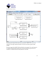
UEISim turns a PowerDNx Ethernet data acquisition module into a target on which you
can run Simulink models and read/write physical I/Os.
The UEISim host software uses the Simulink add-on “Real-time Workshop” to convert
your Simulink model to C code and then cross-compiles it into an executable that runs
directly on the UEISim hardware.
You can access all analog I/Os, digital I/Os, counter timer I/Os offered by PowerDNA
from your Simulink model.
You can experiment with control system design, signal processing, data acquisition and
similar tasks directly from the Simulink environment using its powerful block library
without the need to use any additional tool.
2. Software Installation
The UEISim software runs on a Linux PC or on Windows.
2.1.
Pre-requisites
Before installing the UEISim software make sure that the following software is installed
on your computer:
Matlab R2009a, R2009b, R2010a, R2010b, R2011a, R2011b, R2012a, R212b,
R2013a, R2013b, R2014a, R2014b
Simulink
Real-time Workshop (for older versions of matlab) or Simulink Coder (for
version r2011a and up)
2.2.
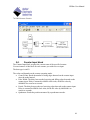
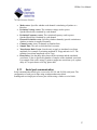
Install UEISim Software for Windows
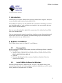
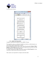
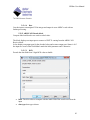
Insert the UEISIM Software CDROM in your CD drive. If the installer doesn’t start
automatically (it depends on whether autorun is enabled or disabled on your PC) run the
ueisim_installer.exe program on the CD-ROM.
5
UEISim User Manual
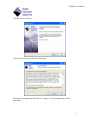
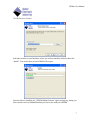
Click on Next to move to the next wizard page.
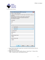
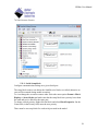
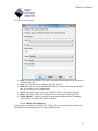
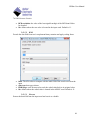
Read the license agreement and click on “I Agree” if you accept the terms of the
agreement.
6
UEISim User Manual
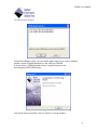
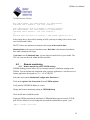
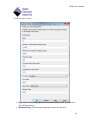
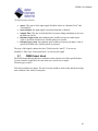
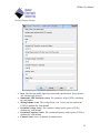
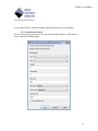
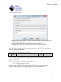
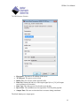
Select the location on your hard drive where you wish to install the software then click
“Install”. You need to have at least 250MB of free space.
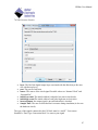
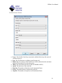
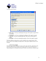
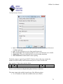
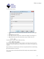
Once the files are installed, the “UEISIM Matlab Selector” applet will pop-up, letting you
select which version of Matlab/Simulink you wish to use with your UEISIM.
7
UEISim User Manual
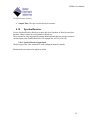
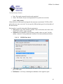
After the installation is done, you can run that applet again if you want to configure
another version of Matlab/Simulink to work with your UEISIM.
You can run the “UEISIM Matlab selector” using the shortcut in the
Start/Programs/UEI/UEISIM menu.
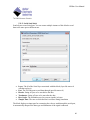
Once all the files are installed, click on “Finish” to exit the installer.
8
UEISim User Manual
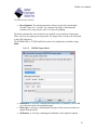
Important Note: In a few rare occasions, we encountered a problem where the Matlab’s
ActiveX automation server was not properly registered which prevented our “UEISIM
Matlab Selector” applet to work.
When that happens the “UEISIM Matlab Selector” applet will pop-up an error message
and you will need to manually configure Matlab’s path:
Start Matlab and at the prompt enter the following commands (change the path to the
location you selected during the installation):
addpath(`c:\program files\uei\ueisim\simulink`)
savepath
2.3.
Install UEISim Software for Linux
Insert the “UEISim” CDROM in your CD drive. You might need to mount it if your
Linux distribution doesn’t detect the CDROM automatically.
To mount it, type:
mount /dev/cdrom /mnt/cdrom
cd /mnt/cdrom
bash install.sh
3. Configuring the UEISim
The IP address must be configured using the serial port.
3.1.
Connecting the serial port console
Connect the serial cable to the serial port on the UEISIM cube and the serial port on your
PC.
You will need a serial communication program:
Windows: ucon, MTTTY, putty.
Linux: minicom or cu (part of the uucp package).
The PowerDNA I/O module uses the serial port settings: 57600 bits/s, 8 data bits, 1 stop
bit and no parity. Run your serial terminal program and configure the serial
communication settings accordingly.
Connect the DC output of the power supply (24VDC) to the “Power In” connector on the
PowerDNA cube and connect the AC input on the power supply to an AC power source.
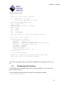
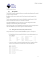
You should see the following message on your screen:
9
UEISim User Manual
U-Boot 1.1.4 (Jan 10 2006 - 19:20:03)
CPU:
MPC5200 v1.2 at 396 MHz
Bus 132 MHz, IPB 66 MHz, PCI 33 MHz
Board: UEI PowerDNA MPC5200 Layer
I2C:
85 kHz, ready
DRAM: 128 MB
Reserving 349k for U-Boot at: 07fa8000
FLASH: 4 MB
In:
serial
Out:
serial
Err:
serial
Net:
FEC ETHERNET
Type "run flash_nfs" to mount root filesystem over NFS
Hit any key to stop autoboot:
5
## Booting image at ffc10000 ...
Image Name:
Linux-2.6.16.1
Created:
2006-11-10 16:07:06 UTC
Image Type:
PowerPC Linux Kernel Image (gzip compressed)
Data Size:
917636 Bytes = 896.1 kB
Load Address: 00000000
Entry Point: 00000000
Verifying Checksum ... OK
Uncompressing Kernel Image ... OK
id mach(): done
...
< lots of kernel messages >
...
BusyBox v1.2.2 (2006.11.03-19:16+0000) Built-in shell (ash)
Enter 'help' for a list of built-in commands.
~ #
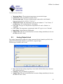
You can now navigate the file system and enter standard Linux commands such as ls, ps,
cd…
3.2.
Configuring the IP address
Your UEISIM cube is configured at the factory with the IP address 192.168.100.2 to be
part of a private network.
You can change the IP address for the current session using the command:
setip <new IP address>
10
UEISim User Manual
3.3.
File system
The UEISIM file system contains the libraries, executables and configuration files needed
to make the system functional.
By default, the file system is stored on the SD card inserted on the front panel of the
UEISIM.
The file system can alternatively be located in a RAM drive loaded from the FLASH
memory or loaded from a remote server using the NFS protocol.
The standard UEISIM file system is read/write to ease the configuration and allow
uploading of model files during the development phase.
Once a model is stable, it is recommended to convert the file system to read-only mode to
render the UEISIM file system resilient against un-scheduled shutdowns.
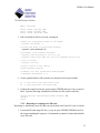
3.3.1. Booting the SD card with system partition read-only
The procedure below converts the standard UEISIM file system to a read only one.
1. Edit /etc/fstab as below to mount a RAM disk at /var (ram disk maximum size is
set to 2MBytes):
/dev/sdcard1
none
none
none
tmpfs
2.
/
/proc
/sys
/dev/pts
/var
ext3
proc
sysfs
devpts
tmpfs
defaults,noatime
defaults
defaults
defaults
defaults,size=2M
1
0
0
0
0
1
0
0
0
0
Create a new script /etc/varsetup.sh with the content below. It setups the folders
needed in /var and maps a few writable folders at /tmp, /mnt and /home
mkdir
mkdir
mkdir
mkdir
mkdir
mkdir
mkdir
mkdir
mkdir
mkdir
/var/tmp
/var/log
/var/lib
/var/lib/misc
/var/spool
/var/spool/cron
/var/spool/cron/crontabs
/var/run
/var/lock
/var/mnt
11
UEISim User Manual
mkdir /var/home
mount --bind /var/tmp /tmp
mount --bind /var/mnt /mnt
mount --bind /var/home /home
3. Edit /etc/inittab as below to execute varsetup.sh
# Mount all filesystem listed in /etc/fstab
::sysinit:/bin/mount –a
# Create and mount non-persistent folders
::sysinit:/etc/varsetup.sh
# Configure local network interface
::sysinit:/sbin/ifconfig lo 127.0.0.1 up
::sysinit:/sbin/route add -net 127.0.0.0 netmask 255.0.0.0 lo
# run rc scripts
::sysinit:/etc/rcS
# Start a shell on the console
ttyS0::respawn:-/bin/sh
# unmount root file system when shutting-down
::shutdown:/bin/umount -a -r
4. Create symbolic links to files stored in /etc that need to be kept writeable.
ln –s /var/resolv.conf /etc/resolv.conf
ln –s /var/layers.xml /etc/layers.xml
5. Connect the console serial port, power-up the UEISIM and press a key to enter UBoot. Type the following commands to load the root file system read-only:
setenv bootargs console=ttyS0,57600 root=62:1 ro
saveenv
reset
3.3.2. Restoring or creating a new SD card
Restoring or initializing a new SD card can only be done on a Linux PC (real or virtual).
1. Locate the SD card image file rfs-x.y.z.tgz on your UEISIM CDROM as well as
the script containing the sequence of commands to partition, format and initialize
a new SD card.
12
UEISim User Manual
2. Connect the SD card via a USB adapter (or directly if your computer has a builtin reader).
3. Type the command dmesg to find out what device node is associated with the SD
card. (Linux kernel outputs messages when it detects a new removable drive)
4. Assuming that /dev/sdb is the SD card device node, type ./createsdcard.sh
/dev/sdb rfs-x.y.z.tgz to partition, format and copy files to the card.
3.3.3. Booting from a RAM drive (no SD card needed)
Booting from a RAM disk is faster than any other method. However the RAM disk size is
limited to 16Mbytes and any data written to the RAM disk is lost when the system shuts
down or reboot.
The RAM disk can only fit in the flash memory of the UEIPAC models based on the
8347 CPU (UEIPAC-1G or UEIPAC-R ).
3.3.3.1.
Customize the RAM drive image
Customizing the RAM drive image is necessary to add your model and tweak the startup
script if you wish to start the model automatically.
This can only be done on a Linux PC. You might need to install the uboot mkimage
utility.
For example under Ubuntu or Debian:
$sudo apt-get install uboot-mkimage
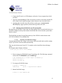
1. Extract compressed RAM disk image from uImage file. The following command
converts the file uRamdisk-x.y.z to ramdisk.gz
$ dd if=uRamdisk-x.y.z bs=64 skip=1 of=ramdisk.gz
21876+1 records in
21876+1 records out
2. Un-compress RAM disk image
$ gunzip -v ramdisk.gz
ramdisk.gz:
66.6% -- replaced with ramdisk
3. Mount RAM disk image
$ mount -o loop ramdisk /mnt
13
UEISim User Manual
Now you can add, remove, or modify files in the /mnt directory. Once you are done, you
can re-pack the RAM disk into a U-Boot image:
1.
Un-mount RAM disk image:
$ umount /mnt
2.
Compress RAM disk image
$ gzip -v9 ramdisk
ramdisk:
66.6% -- replaced with ramdisk.gz
3.
Create new U-Boot image
$ mkimage -T ramdisk -C gzip -n 'My UEISIM RAM disk' -d
ramdisk.gz new-uRamdisk-x.y.z
Image Name:
UEIPAC RAM disk
Created:
Wed Apr 11 17:32:41 2012
Image Type:
PowerPC Linux RAMDisk Image (gzip compressed)
Data Size:
2425561 Bytes = 2368.71 kB = 2.31 MB
Load Address: 0x00000000
Entry Point: 0x00000000
3.3.3.2.
Upload RAM drive image to flash
Uploading the RAM disk image must be done from the boot loader command line using
the TFTP protocol. Make sure you have a TFTP server running on your workstation.
Follow the steps below to upload the RAM disk to memory and boot from it
1. Connect a serial cable to your UEISIM and start a serial terminal software with
communication settings set to 57600,8,N,1
2. Copy the RAM drive image uRamdisk-x.y.z file to the root directory of your
TFTP server
3. Power-up the UEISIM and press any key to enable the boot loader command line.
You should see the prompt ‘=>’
4. Configure the UEISIM’s IP address
=> setenv ipaddr <IP address of the UEISIM>
5. Configure U-Boot to use your host PC as TFTP server:
=> setenv serverip <IP address of your host PC>
14
UEISim User Manual
6. Upload RAM disk:
=> tftp 4000000 uRamdisk-x.y.z
7. Copy the RAM disk to flash:
=> erase fe200000 fe7fffff
=> cp.b 4000000 fe200000 ${filesize}
8. Update bootargs variable to tell the kernel that its root file system is a RAM disk:
=> setenv bootargs console=ttyS0,57600 root=/dev/ram0
rw
9. Change boot command to unpack the RAM disk in memory before starting the
kernel:
=> setenv bootcmd bootm fe000000 fe200000
10.
Save environment to make those changes permanent and reset:
=> saveenv
=> reset
4. Using UEISim add-on from MATLAB/Simulink
4.1.
Convert your model
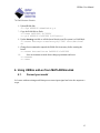
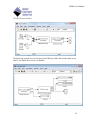
Let’s start with an existing model that process some input signal and view the output on a
scope.
15
UEISim User Manual
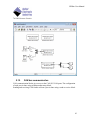
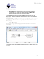
In order to test our model with a real signal, let’s use the UEISim analog input and output
blocks.
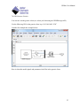
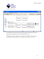
The UEISim I/O blocks are located in the Simulink library:
16
UEISim User Manual
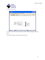
Replace the input sine wave block with an Analog Input block and add an Analog Output
block to generate the result as well as display it on the scope.
17
UEISim User Manual
Double-click on the Analog Input and Output blocks to configure the parameters (see
chapter 5 for details on the parameters for each of the UEISIM block).
4.2.
Create an executable from the model
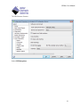
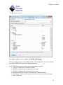
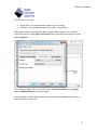
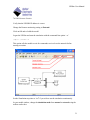
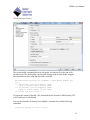
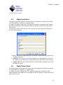
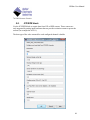
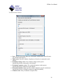
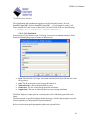
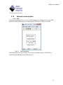
Select the menu option “Simulation/Configuration Parameters…”
Click on the “Solver” option on the left pane and make sure the solver type is set to
“Fixed-step”.
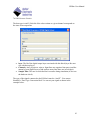
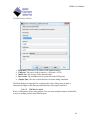
If you are running a Matlab version earlier than R2012a, Select the Real-Time
Workshop option then click on Browse… to change the system target file.
For Matlab R2012a and later, select the Code Generation option then on Browse… to
change the system target file.
Select the UEISim Real-Time Target and click OK.
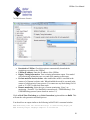
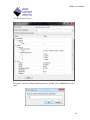
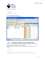
For Matlab R2012a and later, select the Code Generation/Interface option and make
sure Classic call interface is enabled.
18
UEISim User Manual
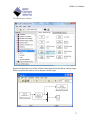
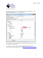
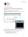
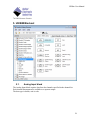
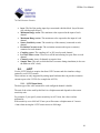
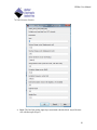
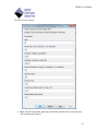
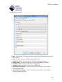
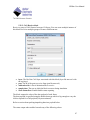
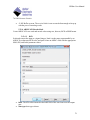
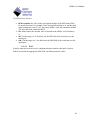
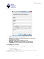
Select UEISim options
19
UEISim User Manual
Download to UEISim: Check this option to automatically download the
simulation executable to the UEISim.
UEISim IP address: Enter the IP address of the UEISim.
Display Timing Information: Turn on timing information output. Your model
will print timing information once a second while running on the target.
Execute model in hard real-time: when enabled the model is executed in the
context of a Xenomai real-time task. When disabled the model is executed in the
context of a high priority Linux process. You cannot use any block doing file I/O
(such as “To File”) in hard real-time mode.
Remote monitoring: Select the type of remote monitoring. ‘None’: no
monitoring, ‘External’: Use Simulink in external mode, ‘UEISIMDesktop’: Use
UEISIMDesktop protocol (more details in section 3.5)
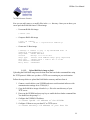
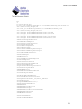
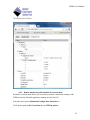
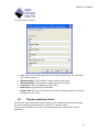
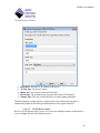
Click on Real-Time Workshop (or on Code Generation) again and then on Build. This
will start the code generation and build process.
You should see an output similar to the following in MATLAB’s command window:
### Generating code into build directory: C:\test\ueisim_ueipac_rtw
### Invoking Target Language Compiler on ueisim.rtw
20
UEISim User Manual
tlc
-r
C:\test\ueisim.rtw
e:\uei_svn\software\powerdna\3.3.x\UEIPAC\Simulink_rtw\ueisim.tlc
-OC:\test\ueisim_ueipac_rtw
-Ie:\uei_svn\software\powerdna\3.3.x\UEIPAC\Simulink_rtw
-IC:\test\ueisim_ueipac_rtw\tlc
-IC:\Program Files\MATLAB\R2007b\rtw\c\tlc\mw
-IC:\Program Files\MATLAB\R2007b\rtw\c\tlc\lib
-IC:\Program Files\MATLAB\R2007b\rtw\c\tlc\blocks
-IC:\Program Files\MATLAB\R2007b\rtw\c\tlc\fixpt
-IC:\Program Files\MATLAB\R2007b\stateflow\c\tlc
-aEnforceIntegerDowncast=1
-aFoldNonRolledExpr=1
-aInlineInvariantSignals=0
-aInlineParameters=0
-aLocalBlockOutputs=1
-aRollThreshold=5
-aZeroInternalMemoryAtStartup=1
-aZeroExternalMemoryAtStartup=1
-aInitFltsAndDblsToZero=1
-aGenerateReport=0
-aGenCodeOnly=0
-aRTWVerbose=1
-aIncludeHyperlinkInReport=0
-aLaunchReport=0
-aGenerateTraceInfo=0
-aForceParamTrailComments=0
-aGenerateComments=1
-aIgnoreCustomStorageClasses=1
-aIncHierarchyInIds=0
-aMaxRTWIdLen=31
-aShowEliminatedStatements=0
-aIncDataTypeInIds=0
-aInsertBlockDesc=0
-aSimulinkBlockComments=1
-aInlinedPrmAccess="Literals"
-aTargetFcnLib="ansi_tfl_table_tmw.mat"
-aIsPILTarget=0
-aLogVarNameModifier="rt_"
-aGenerateFullHeader=1
-aExtMode=0
-aExtModeStaticAlloc=0
-aExtModeTesting=0
-aExtModeStaticAllocSize=1000000
-aExtModeTransport=0
-aRTWCAPISignals=0
-aRTWCAPIParams=0
-aGenerateASAP2=0
-aDownloadToUEIPAC=1
21
UEISim User Manual
-aUEIPACIPAddress="192.168.15.200"
-aGenerateTraceInfo=0
-p10000
### Loading TLC function libraries
.....
### Initial pass through model to cache user defined code
.
### Caching model source code
.............................
### Writing header file ueisim_types.h
.
### Writing header file ueisim.h
### Writing source file ueisim.c
### Writing header file ueisim_private.h
.
### Writing header file rtmodel.h
### Writing source file ueisim_data.c
### Writing header file rt_nonfinite.h
### Writing source file rt_nonfinite.c
.
### TLC code generation complete.
~~~~~~~~~~~~~~~~~~~~~~~~~~~~~~~~~~~~~~~~~~~~~~~~~~~~~~~~~~~~~~~~~~~~~~
### Evaluating PostCodeGenCommand specified in the model
Adding e:\uei_svn\software\powerdna\3326E1~1.X\UEIPAC\SIMULI~1 to
source and include paths
.
### Processing Template Makefile:
e:\uei_svn\software\powerdna\3.3.x\UEIPAC\Simulink_rtw\ueipac.tmf
### ueisim.mk which is generated from
e:\uei_svn\software\powerdna\3.3.x\UEIPAC\Simulink_rtw\ueipac.tmf is up
to date
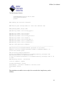
### Building ueisim: .\ueisim.bat
<lots of compiler output>
Created executable: ueisim
Downloading ../ueisim to UEIPAC at 192.168.15.200
Downloaded: ueisim
>>
The simulation executable is now ready to be executed in the /tmp directory on the
UEISim.
22
UEISim User Manual
4.3.
Running the simulation
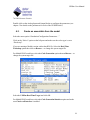
4.3.1. From the command line
Log on the UEISim using the serial port console, Telnet or SSH and run the simulation
executable in the /tmp folder:
/tmp # ./ueisim
StepSize: 0.010000
Model: 201 Option:
Model: 308 Option:
Model: 207 Option:
Model: 205 Option:
Model: 404 Option:
s
100
1
1
1
1
** starting the model **
4.3.2. Using the UEISIM desktop API
UEISim Software comes with an API to remotely control the simulation. The API can be
used from C, C++, C# or VB.NET.
The UEISIM desktop API can start/stop a simulation, read signal and parameter values as
well as timing statistics. It can also write tunable parameter values.
The API is documented in more details in the manual UEISIM Desktop User Manual.
4.4.
Tuning step size and sample time
The sample time parameter in the various I/O blocks determines the maximum amount of
work your model can perform within one step.
To get an idea of your model “load”, you can enable the option “Display Timing
Information” in the “UEISIm Options” configuration panel.
The model will display timing information once a second while running:
**May run forever. Model stop time set to infinity.**
Step completed its work in 0.000085 s, remains 0.000915 s
Min. TET=0.000083, max. TET=0.000148, avg. TET=0.000085
Simulated time 1.000000 s, real time 0.999156 s
Step completed its work in 0.000085 s, remains 0.000915 s
Min. TET=0.000082, max. TET=0.000148, avg. TET=0.000085
Simulated time 2.001000 s, real time 2.000157 s
Step completed its work in 0.000091 s, remains 0.000909 s
23
UEISim User Manual
Min. TET=0.000082, max. TET=0.000148, avg. TET=0.000085
Simulated time 3.002000 s, real time 3.001146 s
Step completed its work in 0.000085 s, remains 0.000915 s
Min. TET=0.000082, max. TET=0.000148, avg. TET=0.000085
Simulated time 4.003000 s, real time 4.002159 s
^C
Executed 4047 iterations in 4.047741 s (999.816935 updates per sec.)
In the output above, the model is running at 1kHz, each step is taking 85us to do its work
out of an allocated 1000us.
The TET values are minimum, maximum and average task execution time.
Simulated time is the expected simulation time. Real time is the measured simulation
time while running on the target.
If real time exceeds simulated time, you are doing too much work in your model. The
CPU can’t execute the task within the allocated time.
4.5.
Remote monitoring
4.5.1. Remote monitoring with UEISIM desktop
UEISIM desktop protocol allows you to remotely monitor a simulation running on the
UEISim. You can monitor the simulation using a generic application, a web browser or a
custom application developed in C/C++, C# or VB.NET.
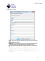
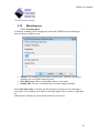
Select the menu option Simulation/Configuration Parameters….
Click on the option Code Generation then on UEISim options.
Verify that the UEISIM IP address is correct
Change the Remote monitoring setting to UEISimDesktop.
Click on OK and re-build the model.
Logon the UEISim and start the simulation. UEISimDesktop protocol uses the TCP/IP
port 2345 by default. You can change the port with the command line option ‘-port’.
/tmp # ./ueisim –port 1234
24
UEISim User Manual
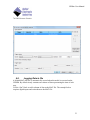
You can now run the generic client (or a client you built using the UEISIM target API)
Use the following URL in the generic client “tcp://192.168.100.2:1234”
Consider for example the example below:
Here is what this model signals and parameters look like in the generic client:
25
UEISim User Manual
The signals available are the 4 outputs of UEISIM Analog Input.
The only tunable parameter is the Gain parameter of the Gain block (You can not change
any of the UEISIM block parameters during simulation)
The UEISIM desktop protocol also makes timing statistics available:
AvgTET: average task execution in seconds
MaxTET: maximum task execution time in seconds
MinTET: minimum task execution time in seconds
ModelExecutionTime: Number of seconds since simulation started
Overloaded: 1 is max task execution time ever becomes greater than the sample
time. 0 otherwise
26
UEISim User Manual
SampleTime: The simulation base sample time in seconds
StopTime: The simulation duration in seconds (-1 for inifinite)
Other signals must be exported to be able to monitor them remotely. For example to
export the signal out of the Signal Conversion block, right-click on the signal wire and
select Properties
Give the signal a name (“Scan”) and click on the Code Generation tab. Set Storage
class to ExportedGlobal to export the signal.
After the model is rebuilt and executed the client show the new Scan signal (which is a
vector of 4 values in this case)
27
UEISim User Manual
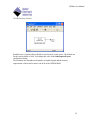
The generic client can change tunable parameters. Double Click on Gain and set a new
value:
28
UEISim User Manual
We can immediately see the effect of changing the gain, the second channel out of the
UEISIM Analog Input block is now multiplied by 10.
The simulation can also be monitored from a web browser. The built-in web server uses
the client’s port incremented by 1.
For example if you start the simulation with /tmp/ueisim_demo –p 1234, you can
monitor the parameter and signals from the URL http://192.168.100.2:1235/ueisim.html
29
UEISim User Manual
4.5.2. Remote monitoring with Simulink in external mode
Simulink’s external mode allows you to remotely monitor a simulation running on the
UEISim from the Simulink application running on your host OC.
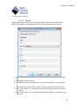
Select the menu option Simulation/Configuration Parameters….
Click on the option Code Generation then on UEISim options.
30
UEISim User Manual
Verify that the UEISIM IP address is correct
Change the Remote monitoring setting to External.
Click on OK and re-build the model.
Logon the UEISim and start the simulation with the command line option ‘-w’.
/tmp # ./ueisim -w
This option tells the model to wait for commands received over the network before
starting execution.
Set the Simulation stop-time to “inf” if you wish to run the simulation continuously.
In your model window, change the simulation mode from normal to external using the
toolbar combo-box.
31
UEISim User Manual
Click on the Connect to target button.
After a few seconds, you will be notified that the connection is established when the
Start real-time code button becomes enabled and the word External appears in the
status bar.
Click on the Start real-time code button to start the simulation.
Double-click on the scope to view the acquired signal as well as the result of the transfer
function.
You can use the scope block to visualize any signal while the model is executing.
Scope only displays 1000 samples per signal, to change the scope’s maximum signal
duration:
Select the menu option Code/External Mode Control Panel
Click on the “Signal & Triggering…” button
Change the duration field in the “Trigger options”
32
UEISim User Manual
4.6.
Logging Data to file
A Matlab MAT data file is automatically created when the model is executed on the
UEISIM. By default it only contains one column of data representing the time of each
step.
Use the “Out” block to add a column of data to the MAT file. The example below
acquires digital inputs and writes them to the MAT file:
33
UEISim User Manual
Simulink uses a circular buffer in RAM to store the most recent values. The default size
for the circular buffer is 1000. You change this value in the Data Import/Export
configuration dialog.
The maximum size depends on the number of signals logged and the memory
requirements of the model so that it can all fit in the UEISIM RAM.
34
UEISim User Manual
The circular buffer containing the latest data points is written to file at the end of the
simulation run. The model prints a notification message if the circular buffer wrapped
(the simulation ran more steps that the buffer can hold)
Executed 52093 iterations in 26.046967 s (1999.964142 updates per
sec.)
*** Log variable tout has wrapped 4 times
using a circular buffer of size 12000
*** Log variable yout has wrapped 4 times
using a circular buffer of size 12000
** created test_fast_ai.mat **
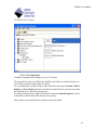
To look at the content of the MAT file, download the file from the UEISIM (using FTP
or SCP) and open it with Matlab.
You can download the file directly from Matlab’s command line with the following
commands:
f=ftp('192.168.100.2','root', 'root')
35
UEISim User Manual
cd(f,'tmp')
binary(f)
mget(f,'untitled.mat')
“rt_tout” is the time of each step
“rt_yout” is the data sent to the Out block.
4.7.
Running a simulation automatically after boot
Edit the file /etc/rc.local and add an entry for any number of programs that you want to
run after the UEISIM complete its power-up sequence.
In the example below, the /etc/rc.local file is modified to run the program “ueisim” at
boot time.
#!/bin/sh
#
# rc.local
#
# This script is executed at the end of the boot sequence.
# Make sure that the script will "exit 0" on success or any other
36
UEISim User Manual
# value on error.
#
listlayers > /etc/layers.xml
sync
devtbl
# start Sample201
/tmp/ueisim &
exit 0
Note that “ueisim” is executed in the background (‘&’ prefix). To stop “ueisim” you must
send the SIGINT signal with the following command (It is equivalent to typing CTRL+C
on the console if “ueisim” was running in the foreground):
killall –SIGINT ueisim
37
UEISim User Manual
5. UEISIM Blockset
5.1.
Analog Input block
The Analog Input block acquires data from the channels specified in the channel list.
Each channel measurement is available as a separate output.
The data type is double; unit is volts.
38
UEISim User Manual
layer: The Id of the analog input layer associated with this block. (layer Ids start
at 0 with the top layer)
Minimum Range: The minimum voltage expected at the input
Maximum Range: The maximum voltage expected at the input
Channel list: Array of channels to acquire from
Input Mode: Single Ended or Differential
Sample Time: The rate at which the block executes during simulation (it also sets
the hardware ADC clock).
5.2.
Thermocouple Input block
The Thermocouple Input block acquires data from the channels specified in the channel
list. Each temperature measurement is available as a separate output.
The data type is double; unit is same as the temperature scale specified in the block
parameters.
39
UEISim User Manual
layer: The Id of the analog input layer associated with this block. (layer Ids start
at 0 with the top layer)
Minimum Range: The minimum temperature expected at the input
40
UEISim User Manual
Maximum Range: The maximum temperature expected at the input
Channel list: Array of channels to acquire from
Thermocouple type: The type of thermocouple connected to each channel.
Supported types are E, J, K, R, S, T, B, N, C
Temperature Scale: The temperature scale for each channel. ‘C’ for Celsius, ‘F’
for Fahrenheit, ‘K’ for Kelvin and ‘R’ for Rankin.
CJC Type: The type of cold-junction compensation. It can be ‘Built-in’ or
‘Constant’.
CJC Value: The temperature constant used when CJC type is set to ‘Constant’
Input Mode: Single Ended or Differential
Sample Time: The rate at which the block executes during simulation (it also sets
the hardware ADC clock).
5.3.
Analog Output block
The Analog Output block updates the voltage generated by the channels specified in the
channel list. Each channel update is specified as a separate input.
The data type is double; unit is volts.
layer: The Id of the analog output layer associated with this block (layer Ids start
at 0 with the top layer)
Channels: Array of channels to generate to
Sample Time: The rate at which the block executes during simulation (it also sets
the hardware DAC clock).
41
UEISim User Manual
5.4.
Digital Input block
The Digital Input block acquires the digital state of the channels specified in the channel
list. Each channel is available as a separate output.
A channel is a group of input lines. The number of input lines contained in each channel
depends on the hardware (for example the DIO-405 groups its input lines in one port of
twelve lines).
The data type is uint32. Each bit of the value read from a given channel corresponds to
the state of one input line.
layer: The Id of the digital input layer associated with this block (layer Ids start at
0 with the top layer)
Channels: Array of ports to read from. Input lines are organized into ports (read
the manual of your digital layer to find out how many lines there are in each port).
Sample Time: The rate at which the block executes during simulation (it also sets
the hardware clock).
5.5.
Digital Output block
The Digital Output block updates the digital state of the channels specified in the channel
list. Each channel is available as a separate input.
A channel is a group of output lines. The number of output lines contained in each
channel depends on the hardware (for example the DIO-405 groups its output lines in one
port of twelve lines).
42
UEISim User Manual
The data type is uint32. Each bit of the value written to a given channel corresponds to
the state of one output line.
layer: The Id of the digital output layer associated with this block (layer Ids start
at 0 with the top layer)
Channels: Array of ports to write to. Input lines are organized into ports (read the
manual of your digital layer to find out how many lines there are in each port).
Sample Time: The rate at which the block executes during simulation (it also sets
the hardware clock).
The type of the signals connected to the DO block must be “uint32”. You can use
Simulink’s “Data Type Conversion block” to convert your signal as shown in the
example below:
43
UEISim User Manual
5.6.
Counter Input block
The Counter Input block acquires the current count of the specified counter.
Use one instance of this block for each counter you wish to use as input.
The data type is uint32.
The value read depends on the counter operating mode:
Count Events: Reads the number of rising edges detected on the counter input
since the model started
Pulse Width: The delay between the last rising and falling edges detected on the
counter input. Delay is returned in 66MHz clock ticks; divide the value by
66000000.0 to convert to seconds.
Period: The delay between the two last rising edges detected on the counter input.
Delay is returned in 66MHz clock ticks; divide the value by 66000000.0 to
convert to seconds.
Quadrature: Reads the position measured by a quadrature encoder.
44
UEISim User Manual
layer: The Id of the digital output layer associated with this block (layer Ids start
at 0 with the top layer)
port: The port to read from.
mode: The operation mode. Possible values are “Count Events”, “Measure Pulse
width”, “Measure period” and “Quadrature Encoder”.
45
UEISim User Manual
source: The source of the input signal. Possible values are “Internal Clock” and
“External Pin”.
inverted input: the input signal is inverted when this is checked.
Sample Time: The rate at which the block executes during simulation (it also sets
the hardware clock).
Debounce input count: the minimum pulse width to accept on counter input.
Value is specified in 66Mz ticks. Smaller pulses are rejected.
Debounce gate count: the minimum pulse width to accept on gate input. Value is
specified in 66Mz ticks. Smaller pulses are rejected
The type of the signals connected to the CI block must be “uint32”. You can use
Simulink’s “Data Type Conversion block” to convert your signal
5.7.
PWM Output block
The PWM output block generates a continuous train of pulses out of the specified timer.
Use one instance of this block for each timer you wish to use as output.
The data type is uint32.
This block contains two inputs: The new low state width (in clock ticks) and the new high
state width (in clock ticks) of each pulse.
46
UEISim User Manual
layer: The Id of the digital output layer associated with this block (layer Ids start
at 0 with the top layer)
port: The port to read from.
source: The source of the clock signal. Possible values are “Internal Clock” and
“External Pin”.
initial low count: The initial width of each pulse low state in clock ticks.
initial high count:The initial width of each pulse high state in clock ticks.
inverted output: the output signal is inverted when this is checked.
Sample Time: The rate at which the block executes during simulation (it also sets
the hardware clock).
The type of the signals connected to the CO block must be “uint32”. You can use
Simulink’s “Data Type Conversion block” to convert your signal
47
UEISim User Manual
5.8.
ICP/IEPE block
Use the ICP/IEPE block to acquire data from ICP or IEPE sensors. Those sensors are
only supported by analog input hardware that can provide excitation current to power the
sensors (for example the AI-211).
The data type of the value returned for each configured channel is double.
48
UEISim User Manual
layer: The Id of the analog input layer associated with this block. (layer Ids start
at 0 with the top/left layer)
Minimum Range vector: The minimum value expected at the input of each
channel
Maximum Range vector: The maximum value expected at the input of each
channel
Sensor Sensitivity vector: The sensitivity of the sensor(s) connected to each
channel
Excitation Current vector: The excitation current used to power sensor(s)
connected to each channel
Coupling vector: The coupling (AC or DC) used on each channel
Low Pass Filter vector: Turns on or off the anti-aliasing low pass filter on each
channel
Channel vector: Array of channels to acquire from
Sample Time: The rate at which the block executes during simulation (it also sets
the hardware ADC clock).
5.9.
LVDT
Use the LVDT blocks to acquire data from LVDT sensors and also simulate voltage
emitted by real LVDT sensors.
Those sensors are only supported by analog input hardware that can provide excitation
current to power the LVDTs (for example the AI-254).
5.9.1. LVDT Input block
The data type of the value returned for each configured channel is double.
The unit of the values read by this block is a displacement and depends on the sensor
sensitivity unit.
For example, if you specify sensor sensitivity in mV/V/mm, the values read are
millimeters.
With sensitivity set to 1000 mV/V/mm you will measure a displacement of -1mm to
+1mm when moving the LVDT sensor across its full range.
49
UEISim User Manual
layer: The Id of the analog input layer associated with this block. (layer Ids start
at 0 with the top/left layer)
50
UEISim User Manual
Minimum Range vector: The minimum value expected at the input of each
channel
Maximum Range vector: The maximum value expected at the input of each
channel
Sensor Sensitivity vector: The sensitivity of the LVDT(s) connected to each
channel
Wiring Scheme vector: The wiring scheme (4 or 5 wires) used to connect
LVDT(s) to each channel
Excitation Voltage vector: The excitation voltage used to power LVDT(s)
connected to each channel
Excitation Frequency vector: The excitation frequency used to power LVDT(s)
connected to each channel
External Excitation vector: Specifies whether channel(s) provide excitation to
LVDT(s) or whether excitation is supplied externally
Channel vector: Array of channels to acquire from
Sample Time: The rate at which the block executes during simulation (it also sets
the hardware ADC clock).
5.9.2. LVDT Simulation block
The data type of the value written to each configured channel is double
The unit of the value to simulate is a displacement and depends on the sensor sensitivity
unit.
For example, if you set sensor sensitivity in mV/V/mm, the values written to the block
must be specified in millimeters.
With sensitivity set to 1000 mV/V/mm, the values written to this block must be in the
range [-1,+1] to simulate an LVDT sensor with a full range of -1mm to +1mm.
51
UEISim User Manual
layer: The Id of the analog input layer associated with this block. (layer Ids start
at 0 with the top/left layer)
Simulated LVDT Sensitivity vector: The sensitivity of the LVDT(s) simulated
by each channel
Wiring Scheme vector: The wiring scheme (4 or 5 wires) used to connect the
LVDT(s) simulated by each channel
Excitation Voltage vector: The excitation voltage used to power LVDT(s)
simulated by each channel
Excitation Frequency vector: The excitation frequency used to power LVDT(s)
simulated by each channel
Channel vector: Array of channels to simulate from
52
UEISim User Manual
Sample Time: The rate at which the block executes.
5.10.
Synchro/Resolver
Use the Synchro/Resolver blocks to acquire data from Synchros or Resolvers and also
simulate voltage emitted by real Synchros or Resolvers.
Those sensors are only supported by analog input hardware that can provide excitation
current to power the Synchro/Resolvers (for example the AI-255 or AI-256).
5.10.1. Synchro/Resolver Input block
The data type of the value returned for each configured channel is double.
Measurements are returned as angles in radian.
53
UEISim User Manual
layer: The Id of the analog input layer associated with this block. (layer Ids start
at 0 with the top/left layer)
Mode vector: Specifies whether a Synchro or a Resolver is connected to each
channel
Excitation Voltage vector: The excitation voltage used to power
Synchro/Resolvers(s) connected to each channel
Excitation Frequency vector: The excitation frequency used to power
Synchro/Resolver(s) connected to each channel
External Excitation vector: Specifies whether channel(s) provide excitation to
Synchro/Resolver(s) or whether excitation is supplied externally
Channel vector: Array of channels to acquire from
54
UEISim User Manual
Sample Time: The rate at which the block executes during simulation (it also sets
the hardware ADC clock).
5.10.2. Synchro/Resolver Simulation block
The data type of the value written to each configured channel is double
The value must be specified as an angle in radian.
55
UEISim User Manual
layer: The Id of the analog input layer associated with this block. (layer Ids start
at 0 with the top/left layer)
56
UEISim User Manual
Mode vector: Specifies whether each channel is simulating a Synchro or a
Resolver
Excitation Voltage vector: The excitation voltage used to power
Synchro/Resolver(s) simulated by each channel
Excitation Frequency vector: The excitation frequency used to power
Synchro/Resolver(s) simulated by each channel
External Excitation vector: Specifies whether channel(s) provide excitation or
whether excitation is supplied externally
Channel vector: Array of channels to simulate from
Sample Time: The rate at which the block executes
Transformer Ratio Vector: Sets the ratio to apply to simulated waveforms
amplitude. For example if excitation amplitude is 10vpp and ratio is 0.5. The
simulated waveforms amplitude will be 5vpp
Phase Delay: Sets the phase delay between the excitation and the simulated
waveforms. Value is specified in number of samples of the simulated waveform.
For example if the card is using 32 points to output one waveform cycle, a phase
delay of 8 is equivalent to a 90 deg. phase shift.
5.11.
Serial port communication
Serial communication blocks give access to the SL-501 and SL-508 serial ports. The
configuration of each port is done using an independent setup block.
Sending and receiving bytes to/from a port is done using a send or receive block.
57
UEISim User Manual
5.11.1. Serial Setup block
Configure communication settings on a given Serial port.
The setup block needs to run before the Send/Receive blocks are called (otherwise an
error will be returned during model execution).
To view/change the execution context order: Select the menu option Format > Block
Displays > Sorted Order and make sure that the setup block has a priority lower than
the send and receive block for the same port.
To change a block priority: Right-click the block and select Block Properties. On the
General tab, in the Priority field, enter the new priority.
There must be one setup block for each serial port used in the model.
58
UEISim User Manual
Layer: The Id of the Serial layer associated with this block (layer Ids start at 0
with the top layer)
Port: The Id of the port to configure (port Ids start at 0)
Buffer size: Size in bytes of the send/receive buffers (determines the maximum
number of bytes able to be received or sent)
Mode: The serial link mode (RS-232/RS-485 HD/RS-485FD)
Speed: The baud rate of the serial link
Data bits: The number of data bits in each transmitted frame
Parity: The method used to calculate the parity bit
Stop bits: The number of stop bits in each transmitted frame
59
UEISim User Manual
5.11.2. Serial Send block
Send a bytes to one Serial port. You can create multiple instance of this block to send
data to the same port at different rate.
Layer: The Id of the Serial layer associated with this block (layer Ids start at 0
with the top layer)
Port: The Id of the port to send data through (port Ids start at 0)
Header: String of bytes to be sent before the data
Terminator: String of bytes to be sent after the data
Byte Order: The endianness used to convert signal(s) to bytes.
Sample Time: The rate at which the block executes during simulation
The block displays an input port for connecting the value to send through the serial port,
it automatically adapts to the data type and dimension of the signal connected.
60
UEISim User Manual
Use the mux block to combine multiple signals that needs to be sent together.
5.11.3. Serial Receive block
Receives bytes from a serial port. You can create multiple instance of this block to
receive data from different ports.
61
UEISim User Manual
Layer: The Id of the Serial layer associated with this block (layer Ids start at 0
with the top layer)
Port: The Id of the port to send data through (port Ids start at 0)
Header: String of bytes that signals the beginning of a data frame
Terminator: String of bytes that signals the end of a data frame
Data Size: Dimension and size of the output signal (for ex [2 4] will output
received data in a 2x4 matrix)
Data Type: The data type used to decode received data
Byte Order: The endianness used to convert received bytes to signal(s).
Sample Time: The rate at which the block executes during simulation
Show Status Port: Enable/disable status reporting
The block displays two output ports:
Data: The signals extracted from the packet payload.
Status: The status (see below).
The status output when enabled can take any of the following values:
0: No bytes were received
N: Number of bytes received
-1: A hardware error occurred
-2: Buffer overrun, The receive block is not executed often enough to keep up
with the pace of incoming bytes
Use the demux block to separate received data into individual signals.
5.11.4. Serial example
The following example sends simulated data to one port receive data from another port.
This example will read back the data sent if both ports are connected with a NULL
modem cable.
62
UEISim User Manual
5.12.
CAN bus communication
CAN communication blocks give access to the CAN-503 CAN ports. The configuration
of each port is done using an independent setup block.
Sending and receiving CAN frames to/from a port is done using a send or receive block.
63
UEISim User Manual
5.12.1. CAN Setup block
Configure communication settings on a given CAN port.
The setup block needs to run before the Send/Receive blocks are called (otherwise an
error will be returned during model execution).
To view/change the execution context order: Select the menu option Format > Block
Displays > Sorted Order and make sure that the setup block has a priority lower than
the send and receive block for the same port.
To change a block priority: Right-click the block and select Block Properties. On the
General tab, in the Priority field, enter the new priority.
There must be one setup block for each port used in the model.
64
UEISim User Manual
layer: The Id of the CAN layer associated with this block (layer Ids start at 0 with
the top layer)
port: The Id of the port to configure (port Ids start at 0)
speed: The speed in bits/s used on the CAN bus connected to this port
frame format: The type of frame sent or received (Standard or Extended)
acceptance code: Acceptance filter code configuration
acceptance mask: Acceptance filter mask configuration
initialization command: A sequence of frames to send to the CAN bus right
before the model start.
Termination command: A sequence of frames to send to the CAN bus right
before the model terminates.
65
UEISim User Manual
The initialization and termination sequences use the following format [ id1 len1
dataMSB1 dataLSB1 id2 len2 dataMSB2 dataLSB2 …]. For example to send a CAN
frame with ID 0x12 and 5 bytes of data (0x01 0z02 0x03 0x04 0x05) use the following:
[ hex2dec(‘12’) 5 hex2dec(‘05’) hex2dec(‘04030201’)]
5.12.2. CAN Send block
Send a group of CAN frames to one CAN port. You can create multiple instance of this
block to send multiple groups of frames at different rate.
layer: The Id of the CAN layer associated with this block (layer Ids start at 0 with
the top layer)
port: The Id of the port to send to (port Ids start at 0)
arbitration ids: A list of arbitration IDs to send
frame sizes: The size of the data payload for each frame
sample time: The rate at which the block executes during simulation
The block displays an input port for connecting the value of the data payload for each
frame.
The data payload is specified using the double data type, which is big enough to carry the
64 bits required for a full payload (8 bytes maximum).
Refer to section about packing/unpacking data into payload below.
66
UEISim User Manual
5.12.3. CAN Receive block
Receive a group of CAN frames from one CAN port. You can create multiple instance of
this block to receive multiple groups of frames at different rate.
layer: The Id of the CAN layer associated with this block (layer Ids start at 0 with
the top layer)
port: The Id of the port to receive from (port Ids start at 0)
arbitration ids: A list of arbitration IDs to receive
sample time: The rate at which the block executes during simulation
Show Status Port: Enable/disable status reporting
The block outputs the value of the data payload of each frame.
The data payload is specified using the double data type which is big enough to carry the
64 bits required for a full payload (8 bytes maximum).
Refer to section about packing/unpacking data into payload below.
The status output when enabled can take any of the following values:
67
UEISim User Manual
0: No CAN frame was received, the signal output contains the data of the last
received frame
1: A new CAN frame was received
-1: A bus error occurred
-2: Buffer overrun, The receive block is not executed often enough to keep up
with the pace of incoming frames
5.12.4. Utility blocks
Utility blocks are used to pack and unpack data stored in the payload of CAN frames that
are sent or received. You can specify the data types and position of multiple signals
within a single CAN frame.
Each signal is specified using four parameters:
data type: the type of the signal, possible values are boolean, int8, uint8, int16,
uint16, int32, uint32, single or double.
endianness: the endianness of the signal, possible values are:
intel for little endian. Bits are counted to the left from the start bit.Bytes are also
counted to the left.
motorola for big endian, Bits are counted to the left from the start bit. Bytes are
counted to the right.
alorotom for backward Motorola format. Bits are counted to the left from the
start bit. Bytes are counted to the right and the byte counting sequence is reversed.
start bit: defines where the least significant bit of a signal's least significant byte is
inserted into the message. It is always (even for big endian signals) counted from
the start of the message (bit 0), and can be in the range (0..63).
bit length: the number of bits used to represent the signal in the 8 bytes data
payload.
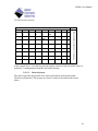
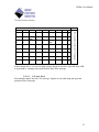
5.12.4.1. Intel format
The least significant bit position, lsb, is specified as the start bit for signals in
Intel format. The bits in an Intel CAN message are always counted as described in the
layout below:
68
UEISim User Manual
Bit number within a byte
4
3
2
5
6
7
X
15
6
X
14
5
X
13
4
X
12
1
0
2
>lsb
10
X
18
1
0
0
9
X
17
8
X
16
1
20
3
X
11
msb<
19
23
22
21
31
30
29
28
27
26
25
24
3
39
38
37
36
35
34
33
32
4
47
46
45
44
43
42
41
40
5
55
54
53
52
51
50
49
48
6
63
62
61
60
59
58
57
56
7
2
Byte number within CAN message
7
In the example above, a ten-bit long message begins at start bit 2 (the lsb of the LSB is at
position 2), counting upward from the start of the message.
5.12.4.2. Motorola format
The start bit specifies the position of the least significant bit in Motorola format.
The bits in a Motorola CAN message are always counted as described in the layout
below:
69
UEISim User Manual
Bit number within a byte
4
3
2
5
6
1
0
7
6
5
4
3
2
1
0
0
15
14
22
X
30
12
X
20
X
28
11
X
19
X
27
10
X
18
>lsb
26
9
X
17
8
X
16
1
23
X
31
13
msb<
21
X
29
25
24
3
39
38
37
36
35
34
33
32
4
47
46
45
44
43
42
41
40
5
55
54
53
52
51
50
49
48
6
63
62
61
60
59
58
57
56
7
2
Byte number within CAN message
7
In the example above, a twelve-bit long message begins at start bit 18 (the lsb of the LSB
is at position 8), counting downward from the start of the message.
5.12.4.3. CAN pack block
Pack multiple signals into one CAN message. Signals are encoded using data type and
position of bits in message.
70
UEISim User Manual
Data types: A cell array containing the data types of the signals to pack in the
message
Endianness: A cell array containing the endianness of the signals to pack
Start bits: A cell array containing the index of the first bit of the signals to pack
Bit length: A cell array containing the number of bits of the signals to pack
The block automatically converts itself to one with the correct number of input ports.
There is always one output port. The output value is ready to be connected to the CAN
Send block.
5.12.4.4. CAN unpack block
Unpack one CAN message into multiple signals. Signals are decoded using data type and
position of bits in message
71
UEISim User Manual
Data types: A cell array containing the data types of the signals to unpack from
the message
Endianness: A cell array containing the endianness of the signals to unpack
Start bits: A cell array containing the index of the first bit of the signals to
unpack
Bit length: A cell array containing the number of bits of the signals to unpack
The block displays one input port to connect a double value coming from the CAN
Receive block. It also displays an output port for each signal to unpack from the CAN
message.
5.12.5. CAN examples
The following example configures two ports on the same CAN-503, sends frames with
Ids 102 and 258 out of port 0 and receives frames with Ids 102 and 258 from port 1.
If port 0 and port1 are connected to the same CAN bus, you will receive what you send.
72
UEISim User Manual
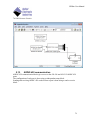
The example below shows how the status output can trigger a subsystem to only execute
portion of your model when a fresh CAN frame has been received.
The triggered subsystem “Trigger Type” is configured to “Rising”. It will execute when
the CAN Receive status goes from 0 to 1 each time a new CAN frame is received.
73
UEISim User Manual
5.13.
ARINC-429 communication
ARINC-429 communication blocks give access to the 429-566 and 429-512 ARINC-429
ports.
The configuration of each port is done using an independent setup block.
Sending and receiving ARINC-429 words to/from a port is done using a send or receive
block.
74
UEISim User Manual
5.13.1. ARINC-429 Setup block
Configure communication settings on a given ARINC-429 port.
The setup block needs to run before the Send/Receive blocks are called (otherwise an
error will be returned during model execution).
To view/change the execution context order: Select the menu option Format > Block
Displays > Sorted Order and make sure that the setup block has a priority lower than
the send and receive block for the same port.
To change a block priority: Right-click the block and select Block Properties. On the
General tab, in the Priority field, enter the new priority.
There must be one setup block for each port used in the model.
75
UEISim User Manual
layer: The Id of the ARINC-429 layer associated with this block (layer Ids start at
0 with the top layer)
port: The Id of the port to configure (port Ids start at 0)
buffer size: the size of the internal buffer allocated to store incoming words until
they are actually received in the model.
speed: The speed in bits/s used on the ARINC-429 bus connected to this port
parity:The parity setting. Set it to None to have full control of the parity bit.
Filtered labels: A sequence of labels to program the hardware filter. Matching
words will be rejected by the ARINc-429 port.
5.13.2. ARINC-429 Send block
Send a group of words to one ARINC-429 TX port. You can create multiple instances of
this block to send multiple groups of words at different rate.
76
UEISim User Manual
Layer: The Id of the ARINC-429 layer associated with this block (layer Ids start
at 0 with the top layer)
Port: The Id of the port to send data through (port Ids start at 0)
Sample Time: The rate at which the block executes during simulation
The block displays an input port for connecting an array of type UINT32 containing raw
values for each word to transmit.
Raw word is a 32 bits value coded as follow:
32 31 30
29
P
SSM
Data
11
10 9
SDI
8
1
Label
Use the ARINC-429 Encode block to encode a value using BCD, BNR or Discrete data
type in the data field.
Refer to section about encoding/decoding words below.
5.13.3. ARINC-429 Receive block
Receive a group of ARINC-429 words from one RX port. You can create multiple
instances of this block to receive multiple groups of words at different rate.
77
UEISim User Manual
layer: The Id of the ARINC-429 layer associated with this block (layer Ids start at
0 with the top layer)
port: The Id of the port to receive from (port Ids start at 0)
max. word count: The maximum number of word to read from the receive buffer
sample time: The rate at which the block executes during simulation
Show Status Port: Enable/disable status reporting
The block outputs a signal of type UINT32. The first value in the array contains the
number of words actually retrieved followed by the raw values of each word.
Raw word is a 32 bits value coded as follow:
32 31 30
29
P
SSM
Data
11
10 9
SDI
8
1
Label
Refer to section about encoding/decoding data field into word below.
The status output when enabled can take any of the following values:
N>=0: Number of words still available in the receive buffer
78
UEISim User Manual
-2: RX Buffer overrun, The receive block is not executed often enough to keep up
with the pace of incoming words
5.13.4. ARINC-429 Encode block
Create ARINC-429 raw word and encode value using raw, discrete, BCD or BNR format.
5.13.4.1. BCD
Scale and convert the input as a signed integer, limit it to the range representable by an
ARINC five-character BCD value, and pack it into an ARINC word with the appropriate
SSM, SDI, and Label parameter values.
label: The 8-bit value inserted in the label field of the word sent over the output
port
data type: data type selector
79
UEISim User Manual
BCD resolution: the value of the least significant digit of the BCD data field to
be encoded and sent. For example, if the associated resolution is .01 and the input
signal contains the value 3.1415, the output ARINC word will contain the number
314 in its data field, encoded in BCD.
lsb: defines where the encoded value is inserted in the ARINC word. Default is
11.
sdi: if in the range 0 to 3, the block sets the SDI field of the word sent over the
output port
ssm: if in the range 0 to 3, the block sets the SSM field of the word sent over the
output port
5.13.4.2. BNR
Scale the input and convert to two's complement binary notation, then pack it into an
ARINC word with the appropriate SSM, SDI, and Label parameter values.
80
UEISim User Manual
label: The 8-bit value inserted in the label field of the word sent over the output
port
data type: data type selector
BNR range: scale factor used to scale the input value which is then limited to [range, range]. Input values outside that range will be limited to ±range.
lsb: defines where the encoded value is inserted in the ARINC word. Default is
11.
sdi: if in the range 0 to 3, the block sets the SDI field of the word sent over the
output port
ssm: if in the range 0 to 3, the block sets the SSM field of the word sent over the
output port
81
UEISim User Manual
5.13.4.3. Discrete
Cast the input as an UINT32 and insert the low order 19 bits in the data field of the
ARINC word along with the appropriate SSM, SDI, and Label parameter values
label: The 8-bit value inserted in the label field of the word sent over the output
port
data type: data type selector
lsb: defines where the encoded value is inserted in the ARINC word. Default is
11.
msb: defines how much of the encoded value is truncated. Default value is 29.
sdi: if in the range 0 to 3, the block sets the SDI field of the word sent over the
output port
ssm: if in the range 0 to 3, the block sets the SSM field of the word sent over the
output port
82
UEISim User Manual
5.13.4.4. Raw
Cast the input to an unsigned 32-bit integer and output it as an ARINC word with no
further processing.
5.13.5. ARINC-429 Decode block
Compare label and decode raw word to scaled value.
The block displays one input port to connect a UINT32 coming from the ARINC-429
Receive block.
It also displays an output port for the decoded value and a status output port. Status is 0 if
the input raw word’s label field didn’t match the label parameter and 1 otherwise.
5.13.5.1. BCD
Decode the data field from 5 digit BCD value to double.
label: The 8-bit value to compare with the label field of the word received on the
input
data type: data type selector
83
UEISim User Manual
BCD resolution: the value of the least significant digit of the BCD data field to
be decoded.
lsb: defines where the raw value is located in the input word. Default is 11.
5.13.5.2. BNR
Decode the data field from two's complement binary notation and apply scaling factor.
label: The 8-bit value to compare with the label field of the word received on the
input
data type: data type selector
BNR range: scale factor used to scale the coded value back to its original value.
lsb: defines where the coded value is located in the ARINC word. Default is 11.
5.13.5.3. Discrete
Extract the data field from the input word and cast it as a double.
84
UEISim User Manual
label: The 8-bit value inserted in the label field of the word sent over the output
port
data type: data type selector
lsb: defines where the coded value is located in the ARINC word. Default is 11.
msb: defines how much of the coded value to extract. Default value is 29.
5.13.5.4. Raw
Cast the input to a double with no further processing
5.13.6. ARINC-429 examples
The following example configures two ports 0 and 6 to run at the same speed. (On 429566, port 6 is internal loopback port; it automatically receives whatever is transmitted out
of port 0).
Port 0 transmits two words where the value from a ramp function block is encoded using
BCD format and labels 102 and 103.
Port 6 receives those words and decodes them back using the same parameters than the
encode block.
85
UEISim User Manual
Note that the first output of the demux block connected to ARINC-429 receive is not
connected. This output contains the number of words received and is ignored in this
example.
The status output of the ARINC-429 decode blocks is also ignored. You could connect it
to a triggered subsystem that would execute when the decoder status goes from 0 to 1
(each time a word that matches the label parameter is decoded).
86
UEISim User Manual
5.14.
Network communication
5.14.1. UDP
UDP communication blocks give access to the Ethernet port. Sending and receiving UDP
packets to/from the Ethernet port is done using the UDP send or UDP receive block.
5.14.1.1. UDP Send block
Send UDP packets to a network host. You can create multiple instance of this block to
send packets to different ports at different rates.
87
UEISim User Manual
Host name: The name or IP address of the destination host
UDP port: The port to send to (must be > 1024 and < 65535)
Buffer size: Size in bytes of the network buffer
Byte Order: The endianness used to pack data in the UDP packet.
Sample Time: The rate at which the block executes during simulation
The block displays an input port for connecting the value of the packet payload, it
automatically adapts to the data type and dimension of the signal connected.
5.14.1.2. UDP Receive block
Receive UDP packets from a network host. You can create multiple instance of this block
to receive multiple packets from different ports.
88
UEISim User Manual
UDP port: The port to receive from (must be > 1024 and < 65535)
Buffer size: Size in bytes of the network buffer
Data Size: Dimension and size of the output signal (for ex [2 4] will output
received data in a 2x4 matrix)
Data Type: The data type used to decode received data
Byte Order: The endianness used to unpack the UDP packet payload.
Sample Time: The rate at which the block executes during simulation
The block displays two output ports:
Data: The signal extracted from the packet payload.
Status: The number of bytes in the payload (0 if no packet was received).
5.14.2. TCP/IP Client
5.14.2.1. TCP/IP Send block
Send TCP/IP packets to a TCP/IP server. You can create multiple instance of this block
to send packets to different servers at different rates.
89
UEISim User Manual
Host name: The name or IP address of the server
TCP/Ip port: The port to send to
Buffer size: Size in bytes of the network buffer
Byte Order: The endianness used to pack data in the TCP/IP packet.
Sample Time: The rate at which the block executes during simulation
The block displays an input port for connecting the value of the packet payload, it
automatically adapts to the data type and dimension of the signal connected.
5.14.2.2. TCP/IP Receive block
Receive TCP/IP packets from a server. You can create multiple instance of this block to
receive multiple packets from different servers.
90
UEISim User Manual
Host name: The name or IP address of the server
TCP/IP port: The port to receive from
Buffer size: Size in bytes of the network buffer
Data Size: Dimension and size of the output signal (for ex [2 4] will output
received data in a 2x4 matrix)
Data Type: The data type used to decode received data
Byte Order: The endianness used to unpack the TCP/IP packet payload.
Sample Time: The rate at which the block executes during simulation
The block displays two output ports:
91
UEISim User Manual
Data: The signal extracted from the packet payload.
Status: The number of bytes in the payload (0 if no packet was received).
5.14.3. Utility blocks
Utility blocks are used to pack and unpack data structures stored in the TCP/IP or UDP
packets that are sent or received. You can specify different data types for each member of
the data structure.
Each member is specified using the following parameters:
data type: the type of the member, possible values are boolean, int8, uint8, int16,
uint16, int32, uint32, single or double.
endianness: the endianness of the member, possible values are ‘intel’ for little
endian, ‘motorola’ for big endian and ‘alorotom’ for backward Motorola format
5.14.3.1.
UEISIM Pack block
Data types: A cell array containing the data types of the structure members to
pack in the buffer
Endianness: A cell array containing the endianness of the signals to pack
92
UEISim User Manual
Byte alignment: The minimum number of bytes occupied by each member.
Possible values are 1,2,4 and 8. For example with align=4, int8 and uint8
members will occupy 4 bytes with 3 zero bytes for padding.
The block automatically converts itself to one with the correct number of input ports.
There is always one output port of type uint8. The output value is ready to be connected
to the UDP Send block.
The UEISIM UDP or TCP/IP Send block needs to be configured to send data of type
uint8.
5.14.3.2.
UEISIM Unpack block
Dimensions: A cell array containing the dimensions (as returned by MATLAB
size() function) of the corresponding signal.
Data types: A cell array containing the data types of the structure members to
unpack from the buffer
Endianness: A cell array containing the endianness of the signals to unpack
93
UEISim User Manual
Byte alignment: The minimum number of bytes occupied by each member.
Possible values are 1,2,4 and 8. For example with align=4, int8 and uint8
members will occupy 4 bytes with 3 zero bytes for padding.
The block displays one input port to connect a uint8 vector coming from the UDP
Receive block. The block automatically converts itself to one with the correct number of
output ports.
The UEISIM TCP/Ip or UDP Receive block needs to be configured to receive a vector of
type uint8 whose dimension is the size occupied by all members defined in the unpack
block (in bytes).
5.14.4. UDP example
The following example acquires analog input channels and sends over the result to a
network host.
The following example sends simulated data and receives it too (IP address must be set to
127.0.0.1).
94
UEISim User Manual
The following example receives 44 bytes from UDP port 64001 and decodes them as one
uint32, one double and a vector of 4 doubles.
95
UEISim User Manual
5.15.
Miscellaneous
5.15.1. Watchdog block
A hardware watchdog can be configured to reboot the UEISIM if the model hangs or
takes too long to complete a step.
Timeout: The watchdog timeout delay in milliseconds. UEISIM will reboot if
watchdog isn’t reset before timeout expires.
Show Reset port: Allows to optionally connect a reset signal
Sample Time: The rate at which the block executes during simulation
When Show Reset Port is checked, this block displays an input port for connecting a
reset signal. The watchdog resets whenever the input signal value is greater or equal than
0.5.
Otherwise the watchdog is reset each time this block is executed.
96