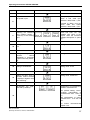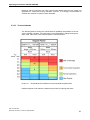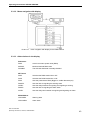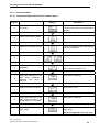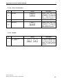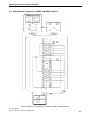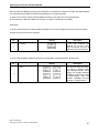
1
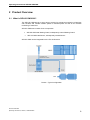
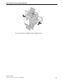
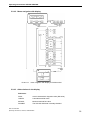
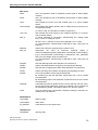
Operating Instructions SIPLUS CMS1000 Preface 1 Product Overview 2 Installation 3 6AT8001-1AA00 Wiring 4 SIPLUS CMS1000 Sensor Commissioning and Diagnosis 5 Technical Data 6 Appendix 7 SIPLUS CMS1000 SIPLUS CMS1000 Bearing Guard 6AT8001-1AA00-1XA0 Operating Instructions - English Release 2011-02 SIPLUS CMS1000 Operating Instructions, 02/2011, A5E01653960 1 Operating Instructions SIPLUS CMS1000 Safety Guidelines This document contains notices which you should observe to ensure your own personal safety as well as to avoid property damage. The notices referring to your personal safety are highlighted in the manual by a safety alert symbol, notices referring to property damage only have no safety alert symbol. Danger Indicates an imminently hazardous situation which, if not avoided, will result in death or serious injury. Warning Indicates a potentially hazardous situation which, if not avoided, could result in death or serious injury. Caution Used with the safety alert symbol indicates a potentially hazardous situation which, if not avoided, may result in minor or moderate injury. Caution Used without the safety alert symbol indicates a potentially hazardous situation which, if not avoided, may result in property damage. Notice Used without the safety alert symbol indicates a potential situation which, if not avoided, may result in an undesirable result or state. When several danger levels apply, the notices of the highest level (lower number) are always displayed. If a notice refers to personal damages with the safety alert symbol, then another notice may be added warning of property damage. Qualified Personnel The device / system may only be set up and operated in conjunction with this documentation. Only qualified personnel should be allowed to install and work on the equipment. Qualified persons are defined as persons who are authorized to commission, to earth, and to tag circuits, equipment and systems in accordance with established safety practices. Intended Use Please note the following: Warning This device and its components may only be used for the applications described in the catalog or technical description, and only in connection with devices or components from other manufacturers approved or recommended by Siemens. Trademarks All designations marked with ® are registered trademarks of Siemens AG. Other designations in this documentation might be trademarks which, if used by third parties for their purposes, might infringe upon the rights of the proprietors. Copyright Siemens AG 2010. All rights reserved. Reproduction, transmission or use of this document or its contents is not permitted without express written authority. Offenders will be liable for damages. All rights, including rights created by patent grant or registration of a utility model or design, are reserved. Disclaimer of Liability We have checked the contents of this document for agreement with the hardware and software described. Since deviations cannot be precluded entirely, we cannot guarantee full agreement. However, the data in the manual are reviewed regularly, and any necessary corrections will be included in subsequent editions. Suggestions for improvement are welcomed. Siemens AG Industry Sector Control Components and Systems Engineering P.O. Box 23 55 90713 Fuerth Germany Siemens AG 2010 Technical data subject to change SIPLUS CMS1000 Operating Instructions, 02/2011, A5E01653960 2 Operating Instructions SIPLUS CMS1000 Table of Contents 1 2 3 4 5 Preface ..................................................................................................................................... 5 1.1 Purpose of this document ......................................................................................... 5 1.2 Required basic knowledge ........................................................................................ 5 1.3 Validity of this document ........................................................................................... 5 1.4 Modification compared with the previous version ..................................................... 5 1.5 Declaration of conformity........................................................................................... 6 1.6 Standards .................................................................................................................. 6 1.7 Directory .................................................................................................................... 7 1.8 Recycling and disposal.............................................................................................. 7 Product Overview ................................................................................................................... 8 2.1 What is SIPLUS CMS1000? ..................................................................................... 8 2.2 What is a SIPLUS CMS1000 Bearing Guard?.......................................................... 9 2.3 What is a SIPLUS CMS1000 Sensor? .................................................................... 10 2.4 Scope of Delivery .................................................................................................... 11 Installation ............................................................................................................................. 12 3.1 3.1.1 3.1.2 Bearing Guard ......................................................................................................... 12 Installation Location, Installation Position, Dimensions .......................................... 12 Label Plate .............................................................................................................. 14 3.2 3.2.1 3.2.2 Sensor ..................................................................................................................... 15 Installation Position, Dimensions ............................................................................ 15 Assembly options .................................................................................................... 16 Wiring ..................................................................................................................................... 17 4.1 General Rules and Regulations for operation of SIPLUS CMS1000...................... 17 4.2 4.2.1 4.2.2 4.2.3 4.2.4 4.2.5 4.2.6 Bearing Guard wiring............................................................................................... 19 Sensor connection................................................................................................... 19 Connection of the Disable-Function ........................................................................ 20 Connection for signaling alarm and warning (signaling contacts ).......................... 20 Connection for motor rotation speed recording with variable rotation speed.......... 21 Connection power supply........................................................................................ 21 Connection assignment........................................................................................... 21 4.3 4.3.1 4.3.2 4.3.3 Sensor Cable........................................................................................................... 22 Connection Sensor cable ........................................................................................ 22 Connection assignment........................................................................................... 22 Sensor cable connection ......................................................................................... 22 Commissioning and diagnosis of Bearing Guard ............................................................. 23 5.1 5.1.1 Commissioning and start-up ................................................................................... 23 Preconditions for commissioning (IBS) ................................................................... 23 5.2 5.2.1 5.2.1.1 5.2.1.2 5.2.1.3 5.2.2 5.2.3 DKW-method........................................................................................................... 23 Learning (Teach-In) operation................................................................................. 24 Teach-In operation with constant rotation speed .................................................... 24 Teach-In operation with variable rotation speed ..................................................... 25 Display before and after Teach-In ........................................................................... 26 Measuring ranges with the DKW-method ............................................................... 27 Violation of limits ..................................................................................................... 27 SIPLUS CMS1000 Operating Instructions, 02/2011, A5E01653960 3 Operating Instructions SIPLUS CMS1000 6 5.2.3.1 5.2.3.2 5.2.3.3 5.2.4 5.2.4.1 5.2.4.2 5.2.4.3 5.2.5 5.2.5.1 5.2.5.2 5.2.5.3 5.2.5.4 Exeeding the warning limit....................................................................................... 27 Exeeding the alarm limit .......................................................................................... 28 Threshold bands...................................................................................................... 29 Menu navigation ...................................................................................................... 31 Description of the display ........................................................................................ 31 Menu navigation with display................................................................................... 32 Abbreviations in the display..................................................................................... 32 Parameterisation ..................................................................................................... 34 Parameterisation with fix motor rotation speed ....................................................... 34 Parameterisation with variable motor rotation speed .............................................. 36 Error / Confirmation ................................................................................................. 38 Disable 39 5.3 5.3.1 5.3.2 5.3.2.1 5.3.2.2 5.3.2.3 5.3.3 5.3.3.1 5.3.3.2 5.3.3.3 5.3.4 5.3.4.1 5.3.4.2 5.3.4.3 RMS-method ........................................................................................................... 40 Selection of frequency range for vibration analysis ................................................ 40 Exceeding of limits .................................................................................................. 40 Exceeding the warning limit..................................................................................... 40 Exceeding the alarm limit ........................................................................................ 40 Threshold bands...................................................................................................... 41 Menu navigation ...................................................................................................... 42 Description of the display ........................................................................................ 42 Menu navigation with display................................................................................... 43 Abbreviations in the display..................................................................................... 43 Parameterisation ..................................................................................................... 44 Parameterisation with fix motor rotation speed ....................................................... 44 Error / Confirmation ................................................................................................. 45 Disable 45 5.4 Simultaneous operation of RMS- and DKW- method ............................................. 46 Technical Data....................................................................................................................... 48 6.1 6.1.1 6.1.2 6.1.3 6.1.4 7 Standards and Approvals ........................................................................................ 48 Bearing Guard ......................................................................................................... 49 Sensor 50 Overall frequency response of the Sensor.............................................................. 51 Notice for approved cleaning .................................................................................. 51 Appendix................................................................................................................................ 52 7.1 Order numbers ........................................................................................................ 52 7.2 7.2.1 7.2.2 Dimensional Drawings............................................................................................. 53 Dimensional Drawing Bearing Guard...................................................................... 53 Dimensional Drawing Sensor.................................................................................. 53 7.3 Overview of chemical resistance of the PUR cable ................................................ 54 7.4 Service & Support in the Internet ............................................................................ 54 7.5 List of Abbreviations ................................................................................................ 55 SIPLUS CMS1000 Operating Instructions, 02/2011, A5E01653960 4 Operating Instructions SIPLUS CMS1000 1 Preface 1.1 Purpose of this document These operating instructions support you to operate the Condition Monitoring System SIPLUS CMS1000. 1.2 Required basic knowledge Basic knowledge of automation technology and condition monitoring equipment is necessary. These operating instructions contain a description of the components, which are valid at the time of publishing the manual. We reserve the right, to enclose product information with current information to new components and updated components. 1.3 Validity of this document This document is valid for the Condition Monitoring System SIPLUS CMS1000. 1.4 Modification compared with the previous version - Redesign and adjustment of pictures - Upgrading chapter 5 with subchapter Error! Reference source not found. and 5.4 - Correction of cable order numbers Notice You find the version of the operating instructions in the footer: A5E01653960. SIPLUS CMS1000 Operating Instructions, 02/2011, A5E01653960 5 Operating Instructions SIPLUS CMS1000 1.5 Declaration of conformity Product name, model SIPLUS CMS1000 6AT8001-xxxxx-xxxx is in compliance with the following standard(s) or documents: - Low-Voltage Equipment Directive 2006/95/EG - EMC Directive 2004/108/EG Harmonized standards applied to all devices - EN 61326 - EN 61010 In accordance with the aforementioned EC directives, the EC Declarations of Conformity are kept available for the relevant authorities by Siemens Aktiengesellschaft Control Components and Systems Engineering I IA CE SE R&D ECW Wuerzburgerstr. 121 D-90766 Fuerth If this product is used outside the European Union, the standards and regulations valid in the owner's country must be observed! 1.6 Standards You will find detailed information in chapter 6.1 of these operation instructions. Notice The specified concessions are only valid according to an authorized label on the product. SIPLUS CMS1000 Operating Instructions, 02/2011, A5E01653960 6 Operating Instructions SIPLUS CMS1000 1.7 Directory The operating instructions describe the hardware of the Condition Monitoring System SIPLUS CMS1000. It contains the following topics: Installation and wiring (Chapter 3 and 4) Commissioning and diagnosis (Chapter 5) Technical data (Chapter 6) Order numbers (Chapter 7.1) List of abbreviations with explanation of the general definitions of the used terms (Chapter 7.5) 1.8 Recycling and disposal The Condition Monitoring System SIPLUS CMS1000 is environmental compatible and recyclable. For environmental compatible recycling and disposal of your old device contact a certified waste disposal for electronic. SIPLUS CMS1000 Operating Instructions, 02/2011, A5E01653960 7 Operating Instructions SIPLUS CMS1000 2 Product Overview 2.1 What is SIPLUS CMS1000? The SIPLUS CMS1000 is an easy start-up system for permanent monitoring of bearings with constant and variable rotation speed in industrial plants as well as for vibration monitoring of machines. SIPLUS CMS1000 consists of two components: SIPLUS CMS1000 Bearing Guard, subsequently named Bearing Guard. SIPLUS CMS1000 Sensor, subsequently named Sensor. SIPLUS CMS can be integrated into the TIA-Architecture. Picture 1 Typical configuration SIPLUS CMS1000 Operating Instructions, 02/2011, A5E01653960 8 Operating Instructions SIPLUS CMS1000 2.2 What is a SIPLUS CMS1000 Bearing Guard? Definition The Bearing Guard analyses the condition of bearing by summarizing vibration data with the method based on VDI 3832 (K(t) in the following called DKW-method. The Bearing Guard also analysis the overall vibration condition of electromechanic machines through broadband measurement of signals between 2Hz/10Hz and 1000Hz and calculating the root mean square value according to ISO 10816, in the following called RMS-method. Application Area The Bearing Guard is suited for the application in a control cabinet (IP20). The compact design of the Bearing Guard enables the application in spacesaving ranges. Easy handling of the Bearing Guard provides a fast commissioning and maintenance. The product is designed for the application on a DIN Rail. Display The Bearing Guard consists of 4 terminal blocks A, B, C and D, one LC-display and some operational control keys. The terminal blocks are mechanically coded.. Picture 2 Bearing Guard SIPLUS CMS1000 Operating Instructions, 02/2011, A5E01653960 9 Operating Instructions SIPLUS CMS1000 2.3 What is a SIPLUS CMS1000 Sensor? Definition The Sensor collects reliable, and with high accuracy the increasing of vibration in one axis and changes it to an analogue, differential signal of voltage. Application Area The Sensor is suited for the application in industrial environment, due to the robust construction and the degree of protection IP67. The compact design of the Sensor enables the application in space-saving ranges. Easy handling of the Sensor provides a fast commissioning and maintenance. The device is applicable for direct use on motor or gearing chassis. Display The Sensor is constructed insulated to ground. It consists of a M12 sensor cable attachment and a M6-thread for mounting on the machine chassis. Picture 3 Sensor SIPLUS CMS1000 Operating Instructions, 02/2011, A5E01653960 10 Operating Instructions SIPLUS CMS1000 2.4 Scope of Delivery What is delivered? Depending on the scope of ordering (see Chapter 7.1): Device SIPLUS CMS1000 Bearing Guard + Manual (short) Device SIPLUS CMS1000 Sensor + Manual (short) CABLE-MEMS-44-xxxx ( xxxx: different cable lengths) Adapter M6/M6; M6/M8 Adapter M6/SPM Unpacking and Checking After unpacking, please check the packet for completeness and all parts for transport damages. Warning Do not use any parts that show signs of damage! SIPLUS CMS1000 Operating Instructions, 02/2011, A5E01653960 11 Operating Instructions SIPLUS CMS1000 3 Installation 3.1 Bearing Guard 3.1.1 Installation Location, Installation Position, Dimensions Installation Location The Bearing Guard is adapted for assembly in control cabinets. The control cabinet must fulfill the request for fire-protection. Protection against electric shock must be warranted. A pull relief of all outward cables must be secured. Installation Position The Bearing Guard is suited for installation on a DIN Rail. Bring the upper guard attachment into the rail and press the device down until catching. Constriction of the installation position: the module must be installed vertical. Distance to keep for correct ventilation: on the side: 0 mm; on the top: 40 mm; on the bottom: 22mm. Assembly recommendation Take care about an efficient grounding of the machine. The connection between motor and base must be bare (without any color) so that a good grounding is guaranteed. Dimensions Chart 1 Dimensions Dimensions (mm) Installation face length 45 mm Installation height 106 mm Installation depth 86 mm SIPLUS CMS1000 Operating Instructions, 02/2011, A5E01653960 12 Operating Instructions SIPLUS CMS1000 Picture 4 Example for installation position Bearing Guard SIPLUS CMS1000 Operating Instructions, 02/2011, A5E01653960 13 Operating Instructions SIPLUS CMS1000 3.1.2 Label Plate Characteristics You can mark the device with a label plate, which is exchangeable. Exchanging the label plate 1. Push the screwdriver in the small opening on the bottom edge of the label plate and hang it out. Picture 5 Label 1 and 2 2. Push the label plate with the finger in the indentation. The order numbers for additional labels (20 mm x 7 mm, ‘pastell-türkis’) can be found in the following catalogue in chapter 7: Niederspannungs-Schalttechnik SIRIUS - SENTRON - SIVACON Katalog LV 1 - 2010 Bestell-Nr. E86060-K1002-A101-A9 © Siemens AG, 2009 or on the Internet-website IA&DT Information- and Downloadcenter SIPLUS CMS1000 Operating Instructions, 02/2011, A5E01653960 14 Operating Instructions SIPLUS CMS1000 3.2 Sensor 3.2.1 Installation Position, Dimensions Installation Position The Sensor should be fixed radial to the rotating axis of the motor and as close as possible near the bearing in the load-zone that shall be monitored. The Sensor is only allowed to be fixed on safe grounded metal parts. The Sensor cable must only be installed in rooms with a maximal environmental temperature of +90º Celsius. Joining the cable to the crankcase is forbidden. Dimensions Chart 2 Dimensions Dimensions (mm) Installation length 64 mm Diameter 22 mm Notice - The Sensor must be fixed form-closed, to assure the correct transmission of the vibration. - The Sensor must not be mounted on curved or coated surfaces - The signal line should be as short as possible - Ensure that there are no additional changeover of material besides bearing and bearing carrier - Oscillating parts of housing are not permitted as measurement position - Measurement should proceed in direction of load - Mounting should be done in direction of highest velocity of vibration. As far as there are no measurement or data available mounting o o should be done in 135 or 225 from A-side - Very low diagnostic characteristic values might be caused by wrong measurement position or faulty installation of the sensor - Measurement of RMS should not be done with sensor mounted on exposed SPM-nipple - Changes in the setting-up area of the motor can influence the diagnostic characteristic values. SIPLUS CMS1000 Operating Instructions, 02/2011, A5E01653960 15 Operating Instructions SIPLUS CMS1000 3.2.2 Assembly options For the assembly of the Sensor (M6-thread) on the motor three adapters are available. If there is no thread to assembly the adapter on the machine a blind hole must be drilled with minimum 10 mm depth and fitting thread. Adapter M6/SPM Is needed for IEC cage rotor motors that are provided with the bearing monitoring option Q01/G50. To check the vibration of the bearing a fitting to measure the SPM-impact momentum is attached. Picture 6 Adapter M6/SPM Adapter M6/M6 Is needed for motors that have a M6-thread for bearing monitoring. Picture 7 Adapter M6/M6 Adapter M6/M8 Is needed for motors that have a M8-thread for bearing monitoring. Picture 8 Adapter M6/M8 SIPLUS CMS1000 Operating Instructions, 02/2011, A5E01653960 16 Operating Instructions SIPLUS CMS1000 4 Wiring 4.1 General Rules and Regulations for operation of SIPLUS CMS1000 Supply voltage The SIPLUS CMS1000 must either be supplied with 24 V DC or with 115 … 240 V AC/DC. (Both voltages at the same time are forbidden!) The following chart shows what you have to observe for the DC24 V-Supply. Chart 3 DC 24V-Supply At… you must ensure that … DC 24 V-Supply safe (electrical) disconnection of low voltage Protection against external electrical influences The following chart shows what you have to observe for the protection of electrical influences or faults. Chart 4 Protection of electrical influences At… you must ensure that … all devices or systems, where the device or system for conduction of electromagnetic failure on SIPLUS CMS1000 is installed grounding (SHIELD) is connected. Supply, signal and bus lines wiring arrangement and installation is correct. Signal and bus lines a line or strand breakage should not lead to an undefined situation of the device or system. Specifications to the wiring: Temperature: the wiring must be installed so that they can not take any damage. The wiring to the Bearing Guard must be applicable for environmental temperature of -25 °C to +60 °C. Important: The cables must not contact hot motor parts. Suitable distance pieces must be designed Insulation thickness: >=0.21 mm (wire insulation) ca. 1 mm (outer cover) conductor cross-section: 0.34 mm² strain-relief: A strain-relief both in the area of the Sensor and the Bearing Guard must be planned. Notice: The wiring must be fixed (binders), so that in case of loosening of a line link no bridging in the insulation can occur. (e.g. primary against 24 V DC). SIPLUS CMS1000 Operating Instructions, 02/2011, A5E01653960 17 Operating Instructions SIPLUS CMS1000 The connection-wires must be bared according to the drawings on the specification plate and when indicated be provided with core cable ends. Conductor cross section: see specification plate. The supply voltage connection (AC/DC 115… 240 V) must be realized according to VDE 0100 and VDE 0160. Core cable ends: the cross section characterization is also valid for core cable ends that have to be sleeve-insulated. Warning Take care that no contactable conductors/wires hang out of the clamps. Danger of electric shock ! SIPLUS CMS1000 Operating Instructions, 02/2011, A5E01653960 18 Operating Instructions SIPLUS CMS1000 4.2 Bearing Guard wiring Caution Only when the installation is correct, protection category IP20 and safe contacting are ensured. Picture 9: Pin assignment and circuit diagram with lamps for warning and alarm display 4.2.1 Sensor connection The Sensor signal has to be connected on clamp unit C, the Sensor feeding voltage to clamp unit D. Chart 5 Connection assignment Sensor Assignment Description / wire color VIB+ Sensor signal: black VIB- Sensor signal: blue VCC_S Sensor feeding voltage: brown GND_S Sensor feeding voltage: white SIPLUS CMS1000 Operating Instructions, 02/2011, A5E01653960 19 Operating Instructions SIPLUS CMS1000 4.2.2 Connection of the Disable-Function By activating the Disable-Input though SPS, frequency converter etc., e.g. during the start-stop procedure of the motor, the Bearing Guard can be disabled. The connections of the Disable-Function are on clamp unit C and D. Connection assignment Chart 6 Connection assignment Disable-Function Assignment Description DIS+ 24 V DC+ DIS- 24 V DC GND Notice: The device is also working without connecting the Disable-Input. 4.2.3 Connection for signaling alarm and warning (signaling contacts ) When the preset limits are reached, warning or alarm-state is signaled via two relay outputs (signaling contacts). The connectors for signaling warning and alarm are located on clamp units A and B. Warning The relay output (warning/alarm) must be fused with: 60°C environment temperature max. 500 mA allowed. (fuse 2.5 A) 40°C environment temperature max. 5 A allowed. (fuse 10 A) Connection assignment signaling contacts Chart 7 Connection assignment warning and alarm signaling Assignment Description 14C relay for voltage up to 230V AC alarm 25C relay for voltage up to 230V AC warning 14NOC (alternatively: 14NCC) *) indicating lamp for alarm 25NOC (alternatively: 25NCC) *) indicating lamp for warning *) NOC means normal open contact, NCC means normally closed contact SIPLUS CMS1000 Operating Instructions, 02/2011, A5E01653960 20 Operating Instructions SIPLUS CMS1000 4.2.4 Connection for motor rotation speed recording with variable rotation speed The rotation speed of motor or transmission shaft that is suitable for the bearing, can be collected either analog -as current or voltage value- or digital (BERO) by a counting input on the device. The connector for the analog recording is on clamp unit D, the connector for the digital recording is on clamp unit B. Connection assignment Chart 8 Connection assignment motor rotation speed / load recording Assignment Description M_I und M_GND rotation speed / load recording with current value 4..20 mA M_U und M_GND rotation speed / load recording with voltage value +-10 V CNT+ und CNT- rotation speed recording with digital signal (BERO) 24 V switching frequency max. 200 Hz 1 impulse per rotation 4.2.5 Connection power supply The device can be supplied with 115…240 V AC/DC or with 24 V DC. The connectors for feed-in 115…240 V AC/DC are on clamp unit A, the one for feed-in 24 V DC on clamp unit C. Caution The supply voltage (AC/DC 115…240 V; 50 Hz/60 Hz und DC 24V) of SIPLUS CMS1000 must be fused with 2.5 A. 4.2.6 Connection assignment Chart 9 Connection assignment power supply Assignment Description L1, N, FE1 Power supply AC/DC 115 … 240 V; 50 Hz/60 Hz; protective earth contact 1 P24, M24, FE2 Power supply DC 24 V; protective earth contact 2 Caution An extern allowed circuit breaker must be provided for separating elements. It must not be arranged in the earth or neutral conductor. This easily operable circuit breaker must have a certain value (16A EU / 20A USA) and must be arranged close to the device (3m). The switch must be marked as appendant to the device. SIPLUS CMS1000 Operating Instructions, 02/2011, A5E01653960 21 Operating Instructions SIPLUS CMS1000 4.3 Sensor Cable Caution Only when the installation is correct, protection category IP67 and safe contacting are ensured. 4.3.1 Connection Sensor cable Caution It is recommended to use standard SIPLUS CMS cables. Using self made cable connections leads to exclusion of warranty. Picture 10 SIPLUS CMS1000 Sensor cable 4.3.2 Connection assignment Chart 10 Connection assignment SIPLUS CMS1000 Sensor cable PIN Assignment 1 VCC_S brown 2 GND_S white 3 VIB- blue 4 VIB+ black shielding 4.3.3 Wire color Display knurled screw Sensor cable connection Push the connector of the Sensor cable in vertical position on the M12 connector plug. Twist the M12 plug with the knurled ring nut tight until it snaps. (about 1/2 rotation) For EMC safety it is obligatory that the Sensor-cable must be grounded across a wide area (e.g. grounding bar). The experience shows that especially with longer cables a screening is obligatory otherwise errors in measurement will occur. Caution Avoid canting between plug connector of the Sensor and M12 connector! SIPLUS CMS1000 Operating Instructions, 02/2011, A5E01653960 22 Operating Instructions SIPLUS CMS1000 5 Commissioning and diagnosis of Bearing Guard 5.1 Commissioning and start-up In delivery status the Bearing Guard has activated both methods, RMS-method and DKW-method. Detailed description of these methods and their relevant parameters can be found in chapter 5.2(DKW) and chapter Error! Reference source not found.(RMS). Please make sure that all parameters for the activated methods are set properly. 5.1.1 Preconditions for commissioning (IBS) 1. Bearing Guard mounted with Sensor (see chapter 3 ). 2. Bearing Guard wired with Sensor (see chapter 4 ). While operating with a frequency inverter it should be avoided to adjust the inverter frequency below 8 kHz. The closer the frequency approaches 8 kHz the more perturbations will occur. If it is not possible to adjust the inverter frequency outside this frequency range the perturbations can be partially filtered out by Teach-In with the LEARNING operation (see chapter 5.2.1 ). However initiating damages might not be detected (oscillations with small amplitude). Only increasing damages will lead to a detectable increased diagnosis value. 5.2 DKW-method A method for calculating a characteristic diagnosis value (DKW according VDI 3832) is detecting damages at an early stage especially for bearings. The DKW-value represents the condition of the bearing. Short disturbances are filtered out. The calculated value will be compared with reference values previously learnt during a Teach-In phase by running a failure free machine in normal condition. The Bearing Guard displays the deviation of actual DKW-value from reference value. Exceeding the threshold value of DKW (deviation from reference), potential-free contacts signal status ‘Warning’ or status ‘Alarm’. The calculated characteristic diagnosis value DKW is shown on the display. SIPLUS CMS1000 Operating Instructions, 02/2011, A5E01653960 23 Operating Instructions SIPLUS CMS1000 5.2.1 Learning (Teach-In) operation Before this sequence of learning is done all parameters must be adjusted. (see Chapter 5.2.5) It must be ensured that the motor has finished its run-in procedure. Parameter „LeaTi“ In menu “LEARN“ the learning of the machine reference condition is done. The Teach-In or reference operation measures the reference condition of the bearing oscillation. It is important to use a machine that is not damaged but has completed the run-in. 5.2.1.1 Teach-In operation with constant rotation speed Parameter „cons“ The recording of the Teach-In value must be done under operating load and with operating rotation speed. All diagnosis conclusions correspond to the Teach-In value of the start conditions of the monitored machine that has been established. The Teach-In value is stored persistent in the Bearing Guard and can be shown via keystroke on the display at every time. The maximum Teach-In time is terminated to one hour. The teach-In becomes more precisely the more time for learning is appointed. SIPLUS CMS1000 Operating Instructions, 02/2011, A5E01653960 24 Operating Instructions SIPLUS CMS1000 5.2.1.2 Teach-In operation with variable rotation speed Parameter „var“ With variable rotation speed the teach-in operation must include all operating points that occur during a normal operating. All rotation speeds occurring in normal operation must be reached during teach-in sequence. One rotation speed can be reached several times during Teach-In sequence. Hint: In case that the entire range of speed is relevant in normal operation mode, a Teach-In sequence with a ramp is recommended. The change of rotation speed during Teach-In must not exceed 180 rpm / min (= 3Hz s-1) Due to restricted number of DKW-supporting points of Bearing Guard corresponding deviations might occur on single rotational speeds in case of highly non-linear characteristic of DKW-curve. Operating points that could not be learnt during Teach-In phase can lead to false alarms. SIPLUS CMS1000 Operating Instructions, 02/2011, A5E01653960 25 Operating Instructions SIPLUS CMS1000 5.2.1.3 Display before and after Teach-In Advantages of the DKW-method for monitoring a bearing: One characteristic to detect a bearing damage Defects are detected early (DKW faster than RMS). Illustrates the defect from the early phase to the breakdown of the bearing. Picture 11 DKW-method SIPLUS CMS1000 Operating Instructions, 02/2011, A5E01653960 26 Operating Instructions SIPLUS CMS1000 5.2.2 All types of bearing defects are detected in one value (inner ring/outer ring, cage, rolling element). No input of bearing values necessary. Only one Teach-in operation necessary. Mostly independent of temperature. Mostly independent of load The sensor is mostly independent of its position compared to a fitting on the bearing shell Measuring ranges with the DKW-method With a raw filter two measurement bands for the analysis of the Sensor signal can be adjusted. Raw filter ON (recommended): 1 kHz to 6.5 kHz In this measurement area low-frequency interruptions are filtered out. The diagnosis is focused on monitoring the bearing. We recommend only using integrated RMS-method to detect unbalances. Both methods DKW and RMS can be run simultaneously (alternating calculation). Raw filter OFF (not recommended): 0 Hz to 6.5 kHz In this measurement area all frequencies are regarded, even potential machine vibrations. We recommend only using integrated RMS-method to detect machine vibration. 5.2.3 Violation of limits While start-up the System both threshold values for warning and alarm must be preset. Basically the limits have to refer to DKW-values that had been calculated during teachin-phase with an undamaged bearing. The Bearing Guard has defaults values that had been determined during laboratory tests with a damaged bearing type 6208. This value can differ from actual DKW-values with different type of bearing. There is no norm to determine to Threshold value. The user must assure that during commissioning the SIPLUS CMS1000 the correct limits are adjusted. 5.2.3.1 Exeeding the warning limit When the characteristic diagnosis value (DKW) exceeds the limit for warning, a relay for signaling this condition is switched on. This relay stays active till the user resets it by keystroke. If the device is switched currentless the state of warning will be reset. This is not a disadvantage since the device detects the existing damage during restart and goes back to warning state. A machine that violates the warning-limit of characteristic diagnosis value (DKW) is usually not applicable for continuous-running operation. But it is commonly allowed to work in this state for a terminated time, until there is an opportunity for corrective actions. SIPLUS CMS1000 Operating Instructions, 02/2011, A5E01653960 27 Operating Instructions SIPLUS CMS1000 Notice If a closer examination of the motor shows no noticeable problems, the warning-limit could be set to a higher level. 5.2.3.2 Exeeding the alarm limit When the characteristic diagnosis value (DKW) exceeds the limit for alarm, a relay for signaling this condition is switched on. This relay stays active till the user resets it by keystroke. If the device is switched currentless the state of alarm will be reset. This is no disadvantage since the device detects the existing damage during restart and goes back to alarm state. Machinery which characteristic diagnosis value (DKW) violate the alarm-limit are usually not applicable for continuous-running operation anymore. It is strongly recommended to maintain the machine and replace it when indicated. Notice If a closer examination of the motor shows no noticeable problems, the warning-limit can be set to a higher level. SIPLUS CMS1000 Operating Instructions, 02/2011, A5E01653960 28 Operating Instructions SIPLUS CMS1000 5.2.3.3 Threshold bands The following threshold bands are regarded as an example to adjust the SIPLUS CMS1000 Bearing Guard limit for warning and alert. To explore the following threshold bands a 5.5 kW motor with bearings of the type 6208 was used. The motor was mounted on stiff basement. The bearings have been specific damaged: lightly damaged: no warning necessary advanced damaged: warning necessary heavily damaged: alert necessary The measurement was taken in the load zone with the following threshold bands proposed. Picture 12 I II, III IV Threshold bands for motors with different rotational speed Rotation speed too slow for DKW-method For both rotation speed ranges different values for warning and alarm can be applied according to the chart. Within this rotation speed range the same value for warning and alarm should be entered . The distance between these values is too small. 5.2.3.3.1 Threshold values for variable rotation speed 200 rpm to 400 rpm If the rotational speed is between 200 rpm and 400 rpm please see orange and red curves in chart above E.g. it is recommended to take following DKW-values at rotational speed 300rpm: (In the example Warning: DKW = 16; Alarm: DKW = 22). 5.2.3.3.2 SIPLUS CMS1000 Operating Instructions, 04/2010, A5E01653960 29 Operating Instructions SIPLUS CMS1000 5.2.3.3.3 Threshold values rotation speed 400 rpm to 1000 rpm Due to stronger increasing DKW-values in speed range between 400 rpm and 1000 rpm the limits can be picked from the threshold band chart (see picture 15) only for limited rotational speed ranges. (e.g. 400-600rpm; 600-800 rpm; 800-1000rpm) 5.2.3.3.4 Threshold values rotation speed greater than1000 rpm For rotational speed greater than 1000 rpm it is recommended to merge the limits for warning and alarm. Notice If a closer examination of the motor shows no noticeable problems the alarm limit can be set to a higher level. SIPLUS CMS1000 Operating Instructions, 04/2010, A5E01653960 30 Operating Instructions SIPLUS CMS1000 5.2.4 Menu navigation 5.2.4.1 Description of the display RUN The default display is „DKW“. With the arrow keys (UP / DOWN) the display content can be changed. In this display mode active values are only displayed, the parameters can not be modified. SET When pressing ENTER for minimum 3 s, the system goes to „SET“ mode. Then ENTERkey leads to each parameter. The parameter values can be changed with the arrow keys (UP / DOWN). Pressing those keys for longer time changes the parameter value faster. When pressing ENTER for minimum 3 s, the system goes back to „RUN“ mode. This futhermore causes the parameters to be saved in a nonvolatile storage. If the parameter “LeaTi“ is set to a value bigger than 0 in „SET“ mode, the system navigates to “LEARN“ mode when leaving the SET-Mode. If parameter ”LeaTi“ is changed back to 0 (counting down from the set value, e.g. 60 to 0 ) this mode will be left. A manual abortion is possible by pressing the arrow keys (UP/DOWN) for minimum 1 s. LEARN The system navigates to ”LEARN“ mode if the parameter ”LeaTi“ is set to > 0 in “SET“ mode. In ”LEARN“ mode the Teach-In process for the reference conditions of the machine will start. The Teach-In process measures the reference conditions of the bearing oscillations. For the Teach-In process it is important not to use a pre-damaged machine. The reference points must be recorded with nominal load and during nominal rotation speed. In case constant rotation speed was adjusted, one characteristic diagnosis value (DKW) is recorded as reference value. With variable rotation speed the teach-in process must get all operating points that occur during normal operating. Operating points that are not taught can lead to false alarms. All diagnosis reports apply to the „Teach-Invalue“-characteristic that was calculated in original condition. For further information about the Teach-In process see chapter 5.2.1 ERROR The system automatically navigates into the „ERROR“ mode on condition that: PRI0 1: Warning „VIB WARN“ PRIO 2: Alarm „VIB ALARM“ PRIO 3: Cable break analog input/rotation speed „M_I BREAK“ This state can be confirmed by pressing both arrow keys (UP/DOWN) at the same time for minimum 1s. The adjusted limit will not be lost. If there are more than one error at the same time, the one with top priority is displayed. If necessary the limits have to be reassessed with the „SET“-menu. For further information see chapter 5.2.3 The error „ Cable break analog input “ can not be quit by the user. It is cancelled automatically when error is resolved. SIPLUS CMS1000 Operating Instructions, 04/2010, A5E01653960 31 Operating Instructions SIPLUS CMS1000 5.2.4.2 Menu navigation with display Picture 13 menu navigation with display for DKW-method 5.2.4.3 Abbreviations in the display RUN-menu DKW: Actual characteristic diagnosis value (DK-value) LeDKW: Learned/stored DK-value MxDKW: Maximal reached DK-value DISABLE The SIPLUS CMS1000 is actually disabled SIPLUS CMS1000 Operating Instructions, 04/2010, A5E01653960 32 Operating Instructions SIPLUS CMS1000 SET-menu RMS: Sets the operation mode of the Bearing Guard (with or without RMSmethod) DKW: Sets the operation mode of the Bearing Guard (with or without DKWmethod). va/co: Sets whether the motor runs with variable (var) or fix (cons) rotation speed. Volt/Curr/Digi: Sets whether the rotation speed is fed as voltage (Volt) current (Curr) or as digital pulse (Digi) (in case of “Digi” one impulse per rotation is expected.) 1Dir / R/L: Sets whether the motor works in one rotational direction or in counterand clockwise rotation. REF_0: If ”Volt“is selected for parameter “Volt/Curr/Digi“ the voltage value REF_0 refers to voltage at 0 rpm. IN case “Curr” s selected, At 0 rpm the parameter ”Curr“ is 4mA. (In case parameter “Volt/Curr/Digi” is selected as “Digi”, REF_M is not relevant) MxRPM: Adjusts the maximum expected motor rotation in rpm. REF_M: Represents the value at maximum rotational speed in Volt/Current/Digital Impulses. (dependant on parameter ”Volt/Curr/Digi“) E.g. in case parameter ”Volt/Curr/Digi“ is selected as ”Volt“, parameter REF_M is the voltage value at maximal rpm. (In case parameter “Volt/Curr/Digi” is selected as “Digi”, REF_M is not relevant) DKW/W: Sets the Warning DKW-value (deviation from reference) W/DEL: Adjusts the delay between recognizing and signaling a Warning. DKW/A: Sets the limit for signaling the alarm state.(deviation from reference) A/DEL: Adjusts the delay time between recognizing and signaling an Alarm. RAWFI: It is recommended to switch this parameter ON. By activating (on) the raw data filter, frequencies from 1 Hz to 6.5 kHz are interpreted. By deactivating (off) the raw data filter, frequencies from 0 Hz to 6.5 kHz are interpreted. NwDKW: If the Bearing Guard is replaced but the sensor will stay with the motor, the previous learnt DKW-value (visible as LeDKW) can be entered into the new Bearing Guard. This feature skips a new Teach-In-phase. LeaTi: Time for teaching the characteristic oscillation value(s) in seconds. Adjustable from 0 to 3600 sec. ERROR-Menu VIB WARN: Warning state VIB ALARM: Alarm state M_I BREAK: Cable break on motor speed input LEARN-menu LEARNING learning state SIPLUS CMS1000 Operating Instructions, 04/2010, A5E01653960 33 Operating Instructions SIPLUS CMS1000 5.2.5 Parameterisation 5.2.5.1 Parameterisation with fix motor rotation speed Step Nr. 1 Display Switch from RUN-mode to SET-mode. Press and hold „ENTER“ until „SET?“ is no longer shown but first parameter will be displayed. Switch off the RMS-method Only as an example in case RMS should be actually deactivated. Default is RMS On. 2 3 Description Switch on the DKW-method 4 Select mode. 5 Setting the WARNING. Setting the delay time in seconds, before WARNING is displayed with relay. Setting value: 0-3600 sec. 6 Setting the limit for ALARM. Setting value: 0-100. Setting the delay time in seconds, before ALARM is displayed with relay. Setting value: 0-3600 sec. 7 8 „fix rotation speed“ limit for Setting value: 0-100. Example for limits see Chapter 5.2.3 SIPLUS CMS1000 Operating Instructions, 04/2010, A5E01653960 34 Operating Instructions SIPLUS CMS1000 Step Nr. Display De-/activating the high-pass filter (>1000Hz). Description Suppression of low-frequency oscillation measurements On (default setting, recommended): interpretation of measurements from 1 kHz to 6.5 kHz 9 Off: interpretation of measurements from 0 Hz to 6.5 kHz. For further information.see chapter 5.2.2. Setting the learned DK-value. 10 (Only relevant in case of fixed rotational speed and device exchange) After exchanging a device, the former during Teach-In calculated „LeDKW“ from old device can be entered into the new device. Setting value: 0-100. Else go on with „ENTER“ 11 Setting the time for the Learncycle. The Teach-In-phase shall include all operating points that appear during normal operating. Setting value: 0-3600 sec. Press ENTER for 0.5 s to get into Learnmode 12 Switch from RUN -mode. SET-mode to Press and hold ENTER until „RUN?“ is no longer shown. Now all adjusted values get stored. SIPLUS CMS1000 Operating Instructions, 04/2010, A5E01653960 35 Operating Instructions SIPLUS CMS1000 5.2.5.2 Parameterisation with variable motor rotation speed Step Nr. Display Discription Switch from RUN-mode to SET-mode. Press and hold „ENTER“ until „SET?“ is no longer shown but first parameter will be displayed. Switch off method the RMS- 2 Only as an example in case RMS should be deactivated. Default is RMS On. 3 Switch on method the DKW- 4 Select „variable rotation speed“ mode. 1 Select whether rotational speed is fed in as current or voltage or digital pulse. „Volt“: The rotational speed/load is fed as voltage between -10 und +10 Volt. „Curr“: The rotational speed/ load is fed as current (4-20 mA) . 5 „Digi“: The rotation speed/load is fed as digital pulses. One digital pulse per rotation. 6 7 Adjust whether the motor works in one rotating direction or in counter-and clockwise rotation. Example 1 (one rotating direction): Motor runs between 0 and 4000 1/min: MxRPM = 4000, Rotat = „1Dir“ Example 2 (counter-and clockwise rotation): Motor runs between -4000 und +4000 : MxRPM = 4000, Rotat = „R/L“ Teach the reference point (rotational speed = 0) of the analog input. Press and hold „UP“ und „DOWN“ until „done“ is displayed, while the voltage/current/pulse for stopped motor is pending. SIPLUS CMS1000 Operating Instructions, 04/2010, A5E01653960 36 Operating Instructions SIPLUS CMS1000 Step Nr. Display Adjust the maximal rotation speed in rpm 8 9 10 Discription Example 1) Motor runs between 0 and 4000 rpm: MxRPM = 4000, Rotat = „1Dir“ Example 2) Motor runs between -4000 and +4000: MxRPM = 4000, Rotat = „R/L“ Teaching the reference point (rotation speed = maximum) of the analog input. Press and hold „UP“ und „DOWN“ until „done“ is displayed, while the maximum voltage/current/pulse is pending. Setting of limit. Setting value: 0-100. WARNING 11 Setting the delay time in seconds, before WARNING is displayed together with relay switching. Setting value: 0-3600 s. 12 Setting of ALARM limit Setting value: 0-100. Setting value: 0-3600 sec. 13 Setting the delay time in seconds, before ALARM is displayed together with relay-switching. De-/activate the highpass filter (>1000Hz). Suppression of low-frequency vibration measurements. 14 On: (default setting, recommended): interpretation of measurements from 1 kHz to 6.5 kHz Off: interpretation of measurements from 0 Hz bis 6.5 kHz. For further information.see chapter 5.2.2. SIPLUS CMS1000 Operating Instructions, 04/2010, A5E01653960 37 Operating Instructions SIPLUS CMS1000 Step Nr. 15 Display Setting the time for the teach-in-phase. Discription The learn cycle should include all operating points, that appear during the normal operating. Operating points that are not learnt can lead to false alarms. Example: the motor runs 5 minutes with 1500 rpm, after that 5 minutes with 4000 rpm, then again with 1500 rpm and so on. The time for the learn cycle should be minimum 10 minutes, or better 20 minutes. Setting value: 0-3600 sec 16 Switch from SET-mode to RUN-mode. Press and hold ENTER until „RUN?“ is not longer shown. Now all adjusted values get stored. 5.2.5.3 Error / Confirmation Nr. display description DKW-Warn Pressing both arrow keys (UP/DOWN) at the same time for minimum 1 s confirms the status „DKW-Warn“.The adjusted limit will not get lost. DKW-Alarm Pressing both arrow keys (UP/DOWN) at the same time for minimum 1 s confirms the status „DKW-Alarm“. The adjusted limit will not get lost. M_I Break This error cannot be removed by keystroke. 1 2 3 It indicates that the cable for current input has been disconnected. (This feature is only available for current interface) SIPLUS CMS1000 Operating Instructions, 04/2010, A5E01653960 38 Operating Instructions SIPLUS CMS1000 The Learn-Processing has been interrupted If a cable break appears during teach-in-phase, the timer and the processing are frozen. Important: If the calibration is realized with ramp function and the cable break appears during the teach-in-phase, the teach-in-phase must be executed again. 4 5.2.5.4 Disable Nr. display description The DKW-Processing has been disabled The SIPLUS CMS1000 Bearing Guard is disabled if 24V is applied on [DIS+; DIS-]. Display toggles between “DISABLE” and the last Value The Learn-Processing has been disabled If Disable is applied during Learn-Processing, the timer LeaTi and the Processing are frozen. 1 2 SIPLUS CMS1000 Operating Instructions, 04/2010, A5E01653960 39 Operating Instructions SIPLUS CMS1000 5.3 RMS-method The calculation of RMS-value (root mean square-value of vibration velocity according DIN ISO 10816) increasing vibrations of a machine can be detected. The RMS-method was implemented according ISO 10816. The vibration signals from the Sensor are analyzed, the root mean square value (RMS) is calculated and shown on the display. The RMS-value is an indicator for general vibration status of the machine. Short disturbances are filtered out. If exceeding tunable limit values potential-free contacts signal warning- or alarm-status. . 5.3.1 Selection of frequency range for vibration analysis Basically the rpm-range has to be adjusted via menu for processing the sensor signal (parameter RPM). The low frequency limit has to be adapted to rotational speed. The user has to determine the major operating mode, bigger or smaller than 600 rpm. 5.3.2 RPM ≥ 600 rpm: (pass filter: 10 .. 1000 Hz) 120 rpm < RPM < 600 rpm: (pass filter: 2 .. 1000 Hz) Exceeding of limits During commissioning both threshold values for warning and alarm-condition must be adjusted. The user can apply to table 5.3.2.3 (according ISO 10816). . Under circumstances the threshold values might differ from recommendations of ISO 10816 and have to be adapted to actual case. 5.3.2.1 Exceeding the warning limit When the root mean square value (RMS) exceeds the adjusted limit for warning, a relay for signaling this condition is switched-on. This relay stays active until the user resets it by keystroke. If the device is switched off the state of warning is reset. This is not a disadvantage because the device will detect the damage at restart and will go warning state again. Machines which exceed the root mean square value (RMS) warning-limit are usually not applicable for continuous-running operation. The reason for machine vibration has to be examined. Commonly machine may be allowed to work in this state for a terminated time until there is an opportunity for corrective actions. 5.3.2.2 Exceeding the alarm limit When the root mean square value (RMS) exceeds the adjusted limit for alarm, a relay for signaling this condition is switched-on. This relay stays active till the user resets it by keystroke. If the device is switched off the state of warning is reset. This is not a disadvantage because the device will detect the damage at restart and will go warning state again. SIPLUS CMS1000 Operating Instructions, 04/2010, A5E01653960 40 Operating Instructions SIPLUS CMS1000 Machines which exceed the root mean square value (RMS) alarm-limit are usually not applicable for continuous-running operation anymore. It is strongly recommended to maintain the machine or replace it when indicated. 5.3.2.3 Threshold bands The following table according ISO 10816 allows a qualitative interpretation of the machine’s vibration condition. The values are a recommendation to adjust warning and alarm level. Valid are the limit values between coloured sections. Picture 14 Threshold bands for different motors with different parameters Rotational speed is not relevant to determine the limits for warning and alarm. SIPLUS CMS1000 Operating Instructions, 04/2010, A5E01653960 41 Operating Instructions SIPLUS CMS1000 5.3.3 Menu navigation 5.3.3.1 Description of the display RUN The default display is „RMS“. With the arrow keys (UP / DOWN) the display content can be changed. In this display mode active values are only displayed, parameters can not be modified. SET When pressing ENTER for minimum 3 s, the system goes to „SET“ mode. Then ENTERkey switches to each parameter next. The parameter values can be changed with the arrow keys (UP / DOWN). Keeping the arrow keys pressed changes the parameter value faster. When pressing ENTER for minimum 3 s, the System goes back to „RUN“ mode. This also causes the parameters to be saved in a nonvolatile storage. ERROR The system automatically navigates into the „ERROR“ mode on following condition: PRI0 1: Warning „VIB WARN“ PRIO 2: Alarm „VIB ALARM“ This state can be confirmed by pressing both arrow keys (UP/DOWN) at the same time for minimum 1 s. The adjusted limit will not be lost. If there are more than one errors at the same time the one with top priority is displayed. For further information see chapter 5.2.3 SIPLUS CMS1000 Operating Instructions, 04/2010, A5E01653960 42 Operating Instructions SIPLUS CMS1000 5.3.3.2 Menu navigation with display Picture 15 menu navigation with display for the RMS-method 5.3.3.3 Abbreviations in the display RUN-menu RMS: Actual root mean square value (RMS) MxRMS: Maximal reached RMS value DISABLE The SIPLUS CMS1000 is actually disabled SET-menu RMS Switches the RMS-method On or Off. DKW Switches the DKW-method On or Off. RPM Sets the predominant RPM. (Bigger or smaller than 600 rpm) RMS/W: Sets the limit for signaling the warning state. W/DEL: Sets the delay between recognizing and signaling a warning. RMS/A: Sets the limit for signaling the alarm state. A/DEL: Sets the delay time between recognizing and signaling an Alarm. ERROR-Menu VIB WARN: Warning state VIB ALARM: Alarm state SIPLUS CMS1000 Operating Instructions, 04/2010, A5E01653960 43 Operating Instructions SIPLUS CMS1000 5.3.4 Parameterisation 5.3.4.1 Parameterisation with fix motor rotation speed Step Nr. 1 2 Display Switch from RUN-mode to SET-mode. Description Press and hold „ENTER“ until „SET?“ is no longer shown and the first parameter is displayed. Switch ON the RMS-method Switch OFF the DKW-method Only as an example in case DKW-method should be deactivated. Select the predominant RPM Setting value: <600 or ≥600 5 Setting the WARNING. Setting value: 0-20. Setting value: 0-3600 sec. 6 Setting the delay time in seconds, before WARNING is displayed and relay is switched. Setting des limit for ALARM. Setting value: 0-100. Setting the delay time in seconds, before ALARM is displayed and relay is switched. Setting value: 0-3600 sec. Switch from RUN -mode. Press and hold ENTER until „RUN?“ is no longer shown. 3 4 7 8 9 limit for Refer for limits to chapter 5.3.2 SET-mode to Now all new adjusted values get active SIPLUS CMS1000 Operating Instructions, 04/2010, A5E01653960 44 Operating Instructions SIPLUS CMS1000 5.3.4.2 Error / Confirmation Nr. display description RMS-Warn Pressing both arrow keys (UP/DOWN) at the same time for minimum 1 s confirms the status „RMS-Warn“.The adjusted limit will not get lost. RMS-Alarm Pressing both arrow keys (UP/DOWN) at the same time for minimum 1 s confirms the status „RMS-Alarm“. The adjusted limit will not get lost. 1. 2. 5.3.4.3 Disable Nr. display The RMS-method been disabled has 1. description The SIPLUS CMS1000 Bearing Guard is disabled when 24V is applied on [DIS+; DIS-], Display will toggle between “DISABLE” and the last calculated value SIPLUS CMS1000 Operating Instructions, 04/2010, A5E01653960 45 Operating Instructions SIPLUS CMS1000 5.4 Simultaneous operation of RMS- and DKW- method Picture 16: Menu for simultaneous operation of RMS- und DKW-method SIPLUS CMS1000 Operating Instructions, 04/2010, A5E01653960 46 Operating Instructions SIPLUS CMS1000 SIPLUS CMS1000 Bearing Guard can be configured for simultaneous operation of RMS- and DKW-method. The calculated values RMS and DKW will be displayed in an alternating way. To step into this modus the parameters RMS and DKW in menu SET have to be switched ON. Further settings for DKW and RMS refer exactly to chapter 5.2 (DKW) and 5.3 (RMS) Specialties: In case of deactivating both methods DKW and RMS an error will be displayed and SET-menu will restart. At least one method has to be activated. Nr. display 01 - ERROR description If the both methods are switched off, this Error message will remind you that at least one has to be activated. 1 In case of deactivating the Bearing Guard by Input DISABLE, following behavior will be shown Nr. display DISABLE 2 description The SIPLUS CMS1000 Bearing Guard is disabled when 24V is applied on [DIS+; DIS-], Display will toggles between “DISABLE” and the last value of RMS-method, after that between “DISABLE” and the last value of DKW-method. SIPLUS CMS1000 Operating Instructions, 04/2010, A5E01653960 47 Operating Instructions SIPLUS CMS1000 6 Technical Data 6.1 Standards and Approvals Product Name Device SIPLUS CMS1000 EMV Directive The product is designed for use in an industrial environment. EMV-requirements: IEC 61010-1:2001 Area of Application Industry Requirements for Emission Immunity IEC 61000-6-4:2006 IEC 61000-4-6:2008 IEC 61326-1:2005 Installation Guide Lines The product meets the requirements if you meet the installation instructions and safetyrelated notices as described in this commissioning manual. EC Declaration of Conformity The EC Declaration of Conformity is available for the responsible authorities according to the abovementioned EC Directive at the following address: SIEMENS AG I IA CE SE WUERZBURGER STR. 121 90766 FUERTH GERMANY Notes for the manufactures of machines This product is not a machine in the sense of the EC Machinery Directive. There is therefore no declaration of conformity relating to the EC Machinery Directive 89/392/ECC for this product. If the product is part of the equipment of a machine, it must be included in the procedure for the declaration of conformity by the manufacturer of the machine. SIPLUS CMS1000 Operating Instructions, 04/2010, A5E01653960 48 Operating Instructions SIPLUS CMS1000 Technical specification 6.1.1 Bearing Guard Interfaces Constructive Layout Power Supply Dimension (H x W x D) 106 mm x 45 mm x 86 mm Minimum distance: front / top / bottom 80 mm / 25 mm / 25 mm Input voltage DC 24 V ( ± 20 % ) Input voltage AC/DC 115 ... 240 V Typ. power loss 3.5 W ( ± 20 % ) Terminal screw M3 (for normal screw drive size 2 or pozidriv 2) Attraction torque 0.8 … 1.2 Nm Design Plastics Weight 300 g Mounting option DIN rail; EN 50022-35x15 2.3 mm Vib- Vib+ (sensor input) Number 1 for SIPLUS CMS1000 Sensor Type Differential interface Input voltage +5V Frequency range 2 Hz … 6.5 kHz Rotation speed input (digital) Rated operational voltage DC Environmental Conditions 24 V Rotation speed input (analog) Voltage DC ± 10 V Typ. current DC 4 ... 20 mA Disable Input Input voltage DC 24 V Thickness ( ± 20 % ) Relay outputs Number 2 changer Switching voltage 250 V AC / 24 V DC Maximum switching current 0,5 A Maximum switching capacity 120 VA / 120 W Isolation 5 kV Transport temperature and storage temperature -40 ... + 85 °C Ambient temperature during operation -25 ... +60 °C Humidity rating 5 ... 95 %, non condensing Safety regulation IEC 61010 - 1 Electromagnetic compatibility IEC 61326 - 1 Protection category IP20 Certificates CE EMV Directive 2004/108/EC Low voltage Directive 2006/95/EC UL In preparation SIPLUS CMS1000 Operating Instructions, 04/2010, A5E01653960 49 Operating Instructions SIPLUS CMS1000 6.1.2 Sensor Interfaces Environmental Conditions Power Supply Transport and storage temperature -40 ... +120 °C Ambient temperature during operation -40 ... +120 °C Relative humidity in operation 5 ... 95 %, condensation permitted Input voltage DC 5V Typ. power loss at DC 5 V 20 mW Sensor connection Measuring range ±5 g Safety regulation IEC 61010 - 1 Frequency range (linear) 2 Hz ... 6.5 kHz Electromagnetic compatibility IEC 61326 - 1 Typ. sensitivity 312 mV/g Protection category IP67 Connector type 4-pin connector M12 Cables 64 mm CABLE-MEMS 4 m, 4 x 0.34 mm² PUR-cable shielded, M12, to open end 6AT8001-1AA00-1AA4 CABLE-MEMS 10 m, 4 x 0.34 mm² PUR-cable shielded, M12, to open end 6AT8001-1AA00-1AB1 CABLE-MEMS 30 m, 4 x 0.34 mm² PUR-cable shielded, M12, to open end 6AT8001-1AA00-1AB3 Constructive Layout Dimension (l) Aperture (Ø) 22 mm (WS22) WS: wrench size Material stainless steel Weight 100 g Drawing Equipment optional Adapter M6/M6; M6/M8 6AT8001-2AA10-1AM0 Adapter M6/SPM 6AT8001-2AA10-1SA0 Certificates CE EMV Directive 2004/108/EC Low voltage Directive 2006/95/EC UL In preparation SIPLUS CMS1000 Operating Instructions, 04/2010, A5E01653960 50 Operating Instructions SIPLUS CMS1000 6.1.3 Overall frequency response of the Sensor Picture 17 Overall frequency response of the Sensor 6.1.4 Notice for approved cleaning The Bearing Guard is only allowed to be cleaned with a dry cloth. The Sensor can be cleaned with water and detergent (s. Cap. 7.3) .Cleaning with vapour stream or high-pressure clean is not allowed. SIPLUS CMS1000 Operating Instructions, 04/2010, A5E01653960 51 Operating Instructions SIPLUS CMS1000 7 Appendix 7.1 Order numbers Product Order numbers (MLFB) SIPLUS CMS1000 Bearing Guard 6AT8001-1AA00 SIPLUS CMS1000 Sensor 6AT8001-1AA00-1XA0 SIPLUS CMS1000 Operation Instructions download see chapter 7.4. Cable 4 x 0.34 mm² PUR-Cable*) screened, M12, open end CABLE-MEMS-44-0004 length 4 m 6AT8001-2AA00-1AA4 CABLE-MEMS-44-0010 length 10 m 6AT8001-2AA00-1AB1 CABLE-MEMS-44-0030 length 30 m 6AT8001-2AA00-1AB3 CABLE-MEMS-44- length variable on request *) chemical reliability see Chapter 7.3. accessories optional Adapter M6/M6; M6/M8 6AT8001-2AA10-1AM0 Adapter M6/SPM 6AT8001-2AA10-1SA0 Further information is available from your local Siemens office and on the homepage www.siemens.com/siplus-cms. SIPLUS CMS1000 Operating Instructions, 04/2010, A5E01653960 52 Operating Instructions SIPLUS CMS1000 7.2 7.2.1 Dimensional Drawings Dimensional Drawing Bearing Guard Picture 18 Dimensional drawing Bearing Guard 7.2.2 Dimensional Drawing Sensor Picture 19 Dimensional drawing Sensor SIPLUS CMS1000 Operating Instructions, 04/2010, A5E01653960 53 Operating Instructions SIPLUS CMS1000 7.3 7.4 Overview of chemical resistance of the PUR cable PUR-cable Chemicals good resistance acetal aldehyde, acetate, acetophenone, aldehyde, amine, alcohol, ammoniac, benzoic aldehyde, fuel, benzophenone, citric acid, cyclohexanone, diesel oil, diethylamine, dimethylamine, grain alcohol, ester, ether, fats, formaldehyde, gearbox oil, hydraulic oil, caustic potash, kerosene, ketones, hydrocarbons aliphatic, arenes, fuels, poor bases, solutions of inorganic salts, machine oil, metal chloride, metal sulfate, metal nitrate, methanol, methylamine, lactic acid, mineral oil, motor oil, natron base, propyl alcohol, seawater, ultraviolet resistance, detergent base, water distilled, water cold, water hot moderate resistance aceton, formic acid, benzol, boric acid, butanoic acid, acetic acid, unsaturated hydrocarbons chlorinated, ozoniferous, nitric acid, sulfuric acid, terpentine not resistant brake fluid, glacial acetic acid, halogens (fluor, chlorine, bromine, jodine), hydrocarbons chlorinated, strong bases, nitrobenzene, hydrochloric acid Service & Support in the Internet In addition to our documentation pool we offer our complete knowledge base on the Internet: www.siemens.com/automation/service&support There you can find: The newsletter, which is constantly updated to provide you with the latest information about your products. The right documents via our search function under Service & Support. The bulletin board, a worldwide knowledge exchange for users and experts. Your local representative for Industry Automation & Drives Technologies via our representatives database. Information about on-site services, repairs, spare parts, and lots more you will find under ”Support”. SIPLUS CMS1000 Operating Instructions, 04/2010, A5E01653960 54 Operating Instructions SIPLUS CMS1000 7.5 List of Abbreviations Abbreviation Item CMS Condition Monitoring System DV Diagnostics Value DKW Diagnosekennwert – diagnostic characteristic value IEPE Integrated Electronics Piezo-Electric MEMS Micro-Electro-Mechanical Systems RMS Root Mean Square TIA Totally Integrated Automation SIPLUS CMS1000 Operating Instructions, 04/2010, A5E01653960 55