1
Tracking Tools 2.4.0
User’s Guide
February 15, 2012
NaturalPoint Corporation
3658 SW Deschutes
Corvallis OR 97333
Copyright 2004-2012 NaturalPoint Inc. DBA OptiTrack. All rights
reserved.
NaturalPoint Publication Number: P-OT-052.1209.EN
Publication Date: September 25, 2012
INTRODUCTION
Information in this user’s manual is subject to change without notice and does not represent a commitment
on the part of NaturalPoint. The software described in this user’s manual is furnished under a license
agreement and may be used only in accordance with the terms of said license agreement.
This document is copyright 2012 NaturalPoint Inc. All rights reserved. No part of this publication may be
reproduced in any form, by any means, without express written permission.
OptiTrack, Tracking Tools and NaturalPoint are trademarks of NaturalPoint Inc.
Windows is a trademark of Microsoft. All other trademarks are property of their respective owners.
For providing VRPN, NaturalPoint would like to thank the NIH National Research Resource in Molecular
Graphics and Microscopy at the University of North Carolina at Chapel Hill, supported by the NIH
National Center for Research Resources and the NIH National Institute of Biomedical Imaging and
Bioengineering.
NaturalPoint Inc. is pleased to provide you with superior optical tracking products, we hope that you enjoy using
Tracking Tools.
Tracking Tools
2
TABLE OF CONTENTS
Introduction ............................................................................................................................................................................ 2
Table of Contents .................................................................................................................................................................... 3
Chapter 1: Getting Started ..................................................................................................................................................... 4
Minimum Requirements ............................................................................................................................................... 4
Installation..................................................................................................................................................................... 5
Activation and Licensing.............................................................................................................................................. 12
The Tracking Tools UI .................................................................................................................................................. 14
Menus.......................................................................................................................................................................... 16
Toolbar ........................................................................................................................................................................ 21
Status Bar .................................................................................................................................................................... 24
Application settings – Options .................................................................................................................................... 25
Chapter 2: Cameras .............................................................................................................................................................. 28
Setup ........................................................................................................................................................................... 28
Camera Controls.......................................................................................................................................................... 30
Camera Groups............................................................................................................................................................ 35
Camera Group Properties ........................................................................................................................................... 37
Synchronization ........................................................................................................................................................... 41
Chapter 3: Calibration .......................................................................................................................................................... 44
3 marker ...................................................................................................................................................................... 44
1 marker ...................................................................................................................................................................... 49
Wanding ...................................................................................................................................................................... 51
Ground plane............................................................................................................................................................... 55
Point Cloud Properties ................................................................................................................................................ 57
Chapter 4: Visualization ...................................................................................................................................................... 61
Application settings – display ...................................................................................................................................... 61
3D Perspective View.................................................................................................................................................... 66
2D Multi Camera ......................................................................................................................................................... 68
Frame Info ................................................................................................................................................................... 70
Chapter 5: Software Usage ................................................................................................................................................. 71
Project files .................................................................................................................................................................. 71
Project explorer ........................................................................................................................................................... 72
Rigid Body Settings ...................................................................................................................................................... 73
Trackables Pane........................................................................................................................................................... 80
Recording and Playback .............................................................................................................................................. 82
Exporting and Streaming ............................................................................................................................................. 83
Technical Support ................................................................................................................................................................. 85
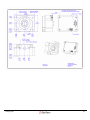
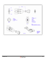
Appendix A: Camera Technical Drawings............................................................................................................................. 86
Glossary ................................................................................................................................................................................. 99
Index.................................................................................................................................................................................... 102
Tracking Tools
3
CHAPTER 1: GETTING STARTED
MINIMUM REQUIRE MENTS
Before getting started, you will need an appropriate copy of the Tracking Tools software. The current, as well as any
previous releases, can be found on our website at:
http://www.naturalpoint.com/optitrack/downloads
Additionally, you will need a computer with the following minimum requirements:
Hyper threaded or multi-core processor
3GB RAM
100MB available HDD space
1 available USB port for V100 or V120 series cameras
1 available USB port for hardware key
Network interface card for S250e cameras
Radeon HD series or NVIDIA GeForce 100 series or higher video card with minimum 256MB memory
Windows XP, Vista, or 7. 32 or 64 bit.
Recommended computer requirements
Intel Core i5 or i7 processor
8GB RAM
>4GB available HDD space
2 available USB ports on separate USB controllers for v100 and v120 cameras
1 available USB port for hardware key
Additional network interface card for S250e cameras
Radeon FirePRO or NVIDIA Quadro series video card with minimum 1GB memory
Windows 7 - 64 bit.
Tracking Tools
4
INSTALLATION
To install Tracking Tools, please download the latest version allowable under your licensing, and save to your hard drive.
If you need more information about versions you can use, you can check the valid dates of your license on our website
at http://www.naturalpoint.com/optitrack/support/.
Please ensure that you have the appropriate permissions to install software on your computer. If you are unsure, or are
using a computer on a domain or other organizational structure, please contact a system administrator to verify that
Tracking Tools can be installed on the machine.
If you are using Windows Vista or 7, start the installation by right clicking on the installer and selecting "Run as
administrator" to ensure that the installer has the appropriate rights.
When installing Tracking Tools, it is strongly recommended that all other programs be closed so that they do not
interfere with installation.
Tracking Tools
5
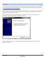
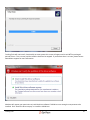
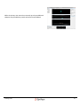
Please read all terms and conditions as outlined in the End User License Agreement presented during installation. If you
agree to the terms and conditions, click yes. If you do not, or have questions, click no to end installation and contact
NaturalPoint for clarification.
Tracking Tools
6
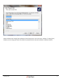
Select the folder that Tracking Tools will install to. The default location is C:\Program Files\NaturalPoint on 32 bit
operating systems, and C:\Program Files (x86)\NaturalPoint on 64 bit operating systems. Under most circumstances, the
default location is appropriate and should remain unchanged. If you would like to change the location, click browse and
select a new folder for installation.
Tracking Tools
7
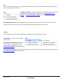
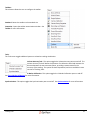
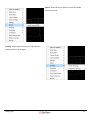
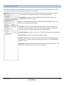
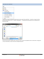
Select the components that you would like to have installed on the machine. By default, all components are selected.
Core components: The Tracking Tools software and licensing wizard.
Documentation: This document.
USB Drivers: USB drivers for OptiTrack V100 and V120 series cameras, hardware key, OptiHub, and other devices
connected through the USB interface.
API: The Tracking Tools API components. This is only required if you plan on integrating Tracking Tools functionality to
your own applications via the API.
Tracking Tools
8
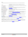
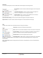
Select the folder that Tracking Tools software will install shortcuts to in the start menu. Default is "Tracking Tools",
however you can change the name of the folder if you would like the shortcuts installed in a different location.
Tracking Tools
9
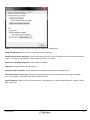
Tracking Tools will now install. Occasionally on some systems this screen will appear and sit at 100% for prolonged
periods of time. This is normal, and the installer should not be stopped. If you believe there is an issue, please contact
NaturalPoint support for more information.
Windows will request your permission to install the driver software if USB drivers are among the components to be
installed. Click "Install this driver anyway" to install the USB drivers.
Tracking Tools
10
Tracking Tools will attempt to register with all file types associated with the application. Click yes to allow, or no to keep
the file types unassociated.
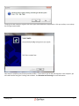
Once setup is complete, press finish to end the installer. If you have not yet run the licensing tool on this computer, you
will need to before using the Tracking Tools software. See Activation and Licensing for more information.
Tracking Tools
11
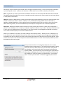
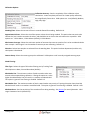
ACTIVATION AND LICEN SING
Before the Tracking Tools software can be used, you
must first activate your software license. The primary
mode of activation and licensing is the OptiTrack
License Tool, installed with Tracking Tools.
The OptiTrack License Tool collects information
required to activate your software. If you have not
previously activated your software, it will perform the
initial activation and lock your software license to the
serial number of the hardware key or camera specified.
Note: If activating software for the first time, please
use the hardware key included with the purchase of
your order. If you did not purchase a hardware key,
the software can be activated by locking it to a camera
instead, however this is not recommended by
NaturalPoint. A license locked to a camera is much less
portable than a hardware key, which can easily be
moved from one computer to another. Licenses locked
to cameras are not eligible for transfer to hardware
keys.
Before activating, please ensure you have an active
internet connection. Fill out all required fields in the
activation tool then click Activate. The License Tool will
communicate with NaturalPoint, verify your
information, and generate a license file. Once the
license file has been generated, it is saved to your computer in the following folder:
2.3.4 and earlier:
{Tracking Tools Installation Directory}\OptiTrack\License
2.3.5 and higher:
%ALLUSERSPROFILE%\Application Data\OptiTrack\License
Once the software is activated, you should not need to access the License Tool again except when adding additional
years of software maintenance to your license. If you have already activated the software, and are attempting to install
the software on an additional computer, you may copy the license files from the previous computer to the new
computer. Additionally, you can use the license tool on the new computer and enter the information as if activating for
the first time. If you have purchased extended years of maintenance for your system, you will need to activate the initial
as well as all additional license extension codes.
If you do not have an active internet connection at the computer you are attempting to install on, you can access the
OptiTrack website from any computer, and register the software via our support page at:
http://www.naturalpoint.com/optitrack/support/
Tracking Tools
12
The license file will be emailed to the provided address, and can be manually saved to the license directory on the
Tracking Tools computer.
If you experience difficulty, or require assistance registering, please contact NaturalPoint Technical Support.
Tracking Tools
13
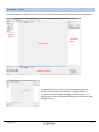
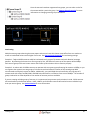
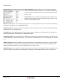
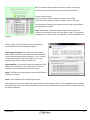
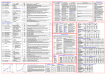
THE TRACKING TOOLS UI
Tracking Tools features a flexible interface which allows it to be easily customized for different tasks and usage patterns.
Project
Explorer
Trackables
Pane
Primary View
Viewport Window
Any pane (except for the Primary View) can be docked to another
location within the application window, or changed to float as a
separate window, by clicking and dragging the pane’s title bar. The
docking behavior can be disabled by holding the control key down while
dragging he pane.
Tracking Tools
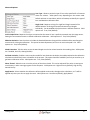
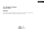
14
While the primary view cannot be removed, up to three additional
viewports may be added to provide enhanced visual feedback.
Tracking Tools
15
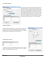
MENUS
Menus within Tracking Tools provide a straightforward interface for accessing software options.
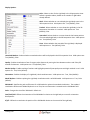
File:
The File menu contains options for loading, saving, and exporting data and projects.
New: Creates a new project to work from.
Open: Opens Tracking Tools projects and individual files. Multiple files may be
selected by holding the control key while clicking on the desired files. Valid file
types are .ttp (Project file), .cal (Calibration file), .tim (Timeline file), and .tra (Rigid
body definition).
Save Project: Saves all current timelines, rigid bodies, and calibration to their
respective files, and overwrites the current project file with all appropriate
information. If no project file exists, it will create one and prompt you for a name.
See Project Files for more information.
Save Project As: Functions as "Save Project" except that a new project file with a new name will be created instead of
automatically overwriting the previous save file.
Export Tracking Data: Allows the user to export the current timeline into .csv (Comma separated value) or .c3D (c3D
standard file, see http://www.c3D.org for more information on the standard). See Exporting for more information.
Save Camera Calibration: Saves the current camera calibration and ground plane orientation to a .cal file.
Save Timeline recording: Saves the current timeline camera data to a .tim file.
Save Trackables: Saves the current defined trackables to a .tra file.
Exit: Closes Tracking Tools.
Tracking Tools
16
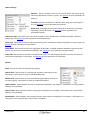
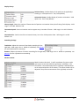
Edit:
The Edit menu provides options for cropping and deleting timeline data, access to the application settings pane, and a
way to restore application defaults.
Tracking Tools Settings: Opens the application settings pane, which can be used to
set preferences and change application behavior. See Application Settings –
Options and Application Settings – Display for more information.
Reset Application Defaults: Resets all application options to the default state, as if starting a new project. Default
settings for all options within the Tracking Tools application can be found throughout this manual.
Timeline:
This sub-menu contains functions for cropping and clearing the currently loaded timeline data.
Clear timeline: Erases all currently loaded
timeline data.
Delete Before Current Position: Deletes all
capture data in the timeline prior to the
current timeline scrubber position. See
Recording and Playback for more information.
Delete After Current Position: Deletes all capture data in the timeline after the current timeline scrubber position. See:
Recording and Playback for more information
Tracking Tools
17
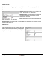
View:
The View menu provides options to open and close various panes within the UI, as well as toolbar customization.
Show All Panes: This option turns all panes on and displays them on screen.
Hide All Panes: This option removes all panes from the application, leaving only the
primary view window.
Project Explorer: This option toggles the Project explorer pane on and off. See
Project Explorer for more information.
Camera Calibration: This option toggles both the 3 Marker and 1 Marker Camera
Calibration panes on and off.
Camera Group Properties: This option toggles the Camera Group Properties pane
on and off. See Cameras - Camera Group Properties for more information.
Recording and Playback: This option toggles the Recording and Playback pane on
and off. See Recording and Playback for more information
Trackable Properties: This option toggles the Trackables pane on and off. See
Trackables Pane for more information
Frame Information: This option toggles the Frame Information pane on and off. See Frame Info for more information.
Streaming Pane: This option toggles the Streaming Pane on and off. See Streaming for more information.
Viewport 1 (2, 3) Pane: These options turn the additional viewport panes on and off. This allows up to 4 viewports
(including the base viewport) to be open for different views of the volume. See Visualization for more information.
Status bar: Toggles the Status Bar on and off. See Status Bar for more information.
Tracking Tools
18
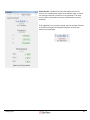
Toolbars:
This submenu allows the user to configure the toolbar.
Standard: Resets the toolbar to the standard size
Customize: Opens the toolbar customization window. See
Toolbar for more information.
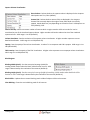
Tools:
The Tools menu toggles additional panes not related to tracking visualization.
Volume Accuracy Tool: This option toggles the Volume Accuracy pane on and off. The
Volume Accuracy Tool will detect the presence of a calibration wand and measure the
distance between the two outermost points, providing a measurement for the
accuracy of the reading. This option has been deprecated, and is not available in most
versions of Tracking Tools.
3-Marker Calibration: This option toggles the 3-Marker Calibration pane on and off.
See Three Marker Calibration for more information.
Synchronization: This option toggles the Synchronization pane on and off. See Synchronization for more information.
Tracking Tools
19
Community:
The Community menu gives you access to NaturalPoint Technical Support and training materials.
Ask a Question: Launches a browser window and navigates to the Tracking Tools
forums.
Tutorial & Training Videos: Launches a browser window and navigates to a
collection of training videos for the Tracking Tools software.
Submit Feedback: Opens a window to submit feedback such as comments,
feature requests, or bug reports to NaturalPoint.
OptiTrack Products Catalog: Launches a browser window and navigates to the OptiTrack web store.
Support Forums: Launches a browser window and navigates to the main NaturalPoint forums page.
Help:
The Help menu provides access to information about the Tracking Tools software.
Topic Index: Launches the Tracking Tools documentation.
News: Opens the news window and displays the latest news items for Tracking Tools.
Check for updates: Checks to see if any updates are available for Tracking Tools. If
updates are available, links will be provided to download the new version.
Show Quick Start: Launches the application quick start pane.
Startup News Check: Toggles whether Tracking Tools should check for news updates
on startup. If enabled and there is a news update, then it will be automatically displayed after Tracking Tools has
finished loading.
About Tracking Tools: Displays licensing and version information, connected devices, and a list of installed software
components.
Tracking Tools
20
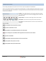
TOOLBAR
The Toolbar allows one click access to many of the functions of Tracking Tools. The Toolbar comes standard with basic
icons, and can be further customized via the View menu.
Customize Toolbar:
By clicking on customize toolbar, you have the option to add or remove icons from the toolbar, and even remove entire
bars from the system. The customize window is divided into 4 tabs.
Toolbars: This tab allows the user to add and remove toolbars from the Tracking Tools header by checking or
unchecking a particular toolbar. Users can add additional toolbars by clicking "New", and giving the new toolbar a name.
Tracking Tools
21
Commands: The commands tab lists all options that can be put onto a toolbar. Icons are divided into separate
categories, and can be dragged from the window into an existing toolbar. Commands with an icon next to them will
place the icon on the toolbar. If the command does not have an icon, the entire text will be placed as a button on the
toolbar.
Keyboard: The keyboard tab allows the user to create hotkeys and assign them to various functions within Tracking
Tools. The functions are categorized through the drop down at the top of the window, and hotkeys are placed by
clicking the shortcut key textbox then pressing the key you would like to assign to the selected task.
Tracking Tools
22
Options: The options tab contains general options for toolbars in Tracking Tools.
Always show full menus: Forces menus to show all items immediately.
Show full menus after a short delay: Will show partial menus at first, then auto expand after a pre-determined amount
of time. This option is not available if “Always Show Full Menus” is selected.
Reset menu and toolbar usage data: Resets toolbars to default.
Large Icons: Changes toolbar icons to large size.
Show ScreenTips on toolbars: Allows help balloons to appear when you hover over toolbar icons.
Show shortcut keys in ScreenTips: Displays associated keyboard shortcuts in balloons when hovering over toolbar
icons. Not available unless Show ScreenTips on toolbars is active.
Menu Animations: Selects the style of menu animation. Valid options are: (System default) (default), Random, Unfold,
Slide, Fade, None.
Tracking Tools
23
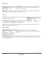
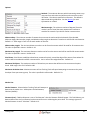
STATUS BAR
The Status Bar shows information on current status of Tracking Tools. While the status bar normally appears at the
bottom of the main Tracking Tools window in one piece, it is broken up here for easier viewing due to its size.
Status: Shows the current status of Tracking Tools.
Incoming Date Rate: Shows the current rate at which information is coming into Tracking Tools from the cameras. The
Data Rate is measured in Bytes per second.
Point Cloud: Shows the amount of time taken by the computer to reconstruct the point cloud(s).
Latency: Shows the total amount of time between the frame being captured and the software rendering the result,
including point cloud calculation and streaming if applicable.
Display: Shows the current rate that Tracking Tools is being rendered to your display.
Cameras: Shows the current rate of capture for the connected cameras in Frames per Second.
CAP/NUM/SCRL: Indicates if Caps Lock, Num Lock, and Scroll Lock are active. The word will be in light gray if they are
not active, black if they are.
Tracking Tools
24
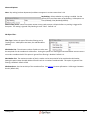
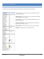
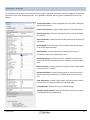
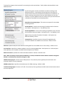
APPLICATION SETTINGS - OPTIONS
Standard Tracking Tools settings can be adjusted through the Application Settings panel. The panel can be accessed
through the Tracking Tools Settings option in the Edit menu.
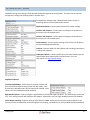
The Application Settings panel is divided into 6 sections to help in
organizing options into easily identifiable clusters.
Application options: Contains general options for marker tracking.
Interface: 2D Viewport: Contains options relating to the operation of
the mouse in the 2D viewport pane.
Interface: 3D Viewport: Contains options relating to the operation of
the mouse in the 3D viewport pane.
Camera Button: Contains options relating to the function of the button
on cameras equipped with buttons.
Timeline: Contains options for the playback and recording of timelines in
Tracking Tools software.
C3D Export Options: Contains options for unit of measurement and axis
identification when exporting files into C3D format. For more
information, visit http://www.c3D.org.
Application Options:
Track Selected Markers: Allows the user to select a marker and
have the selection follow through frames until the marker is lost.
If set to false, selected markers will be frozen until released. Valid
Options are True (enabled) and false (disabled).
Right Handed System: Used to configure a right handed or left handed coordinate plane. This selection only affects the
GUI. The Tracking Tools API will always be Left-Handed. Valid options are True (right handed) and False (left handed).
Active Marker Labeling: Enables tracking of active beacons. Note: Setting this to true without active beacons in the
system will cause unpredictable results and highly erratic tracking. Valid options are True (enabled) and false (disabled).
Tracking Tools
25
Interface: 2D Viewport:
Left Mouse Button: Selects the function of the left mouse button
in the 2D viewport window. Valid options are: Draw mask
(default), Pan Viewport.
Middle Mouse Button: Selects the function of the middle mouse button in the 2D viewport window. Valid options are:
Draw mask, Pan Viewport (default).
Interface: 3D Viewport:
Left Mouse Button: Selects the function of the left mouse button
in the 3D viewport. Valid options are: Pan Viewport, Rotate
viewport, Select (default).
Middle Mouse Button: Selects the function of the middle mouse
button in the 3D viewport. Valid options are: Pan Viewport
(default), Rotate viewport, Select.
Right Mouse Button: Selects the function of the right mouse
button in the 3D viewport. Valid options are: Pan viewport,
Rotate Viewport (default), Select.
Pan Sensitivity: Allows the user to make mouse panning more or less sensitive. A higher value will allow for faster
movement. Conversely, a lower number will allow for more deliberate adjustments. Valid range is 1 to 200 (default
100).
Rotate Sensitivity: Allows the user to make mouse rotating more or less sensitive. A higher value will allow for faster
movement. Conversely, a lower number will allow for more deliberate adjustments. Valid range is 1 to 200 (default
100).
Invert Pan: Allows the user to select an inverted mouse panning motion. This allows the user to move the object rather
than the tracking space. Valid options are True, False (default).
Invert Rotate: Allows the user to select an inverted mouse rotation. This allows the user to rotate the object rather
than the tracking space. Valid options are True, False (default).
Zoom to mouse: This option allows the user to select the mouse pointer as the focal point for zooming. If set to false,
zoom will occur based on the heading of the virtual camera. Valid options are: True (default), False.
Tracking Tools
26
Camera Button:
Switch to MJPEG: Controls whether the button will switch the camera to
MJPEG mode and back to the default camera group record mode. Valid
options are: True (default), False.
Boost Exposure: Controls whether the camera button will switch the camera to maximum exposure and back to the
default camera group exposure. Valid options are: True (default), False.
Timeline:
Playback speed %: Controls the playback speed of the current timeline file.
Valid range is 1 to 800 (default 100).
Loop Playback: Sets the playback engine to loop from the last frame to the
first and continue playing. When playing in reverse, loop will occur from
frame 1 to the last frame. Valid options are: True (default), False.
Start Record: Allows the user to change the function of the record button when a timeline is already present. Valid
options are: New Recording (default), Append.
C3D Export Options:
Units: Allows the user to select the base unit of measurement for
positioning in C3D export. Valid options are: Meters (default), Centimeters,
Millimeters.
Coordinate (axis) Axis: Allows the user to select translations for movement along axes for C3D export. Valid options
are: Positive X Axis, Positive Y Axis, Positive Z Axis, Negative X Axis, Negative Y Axis, Negative Z Axis. Default options are
Positive (axis) Axis respectively.
Tracking Tools
27
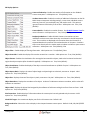
CHAPTER 2: CAMERAS
SETUP
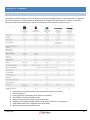
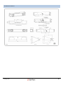
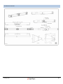
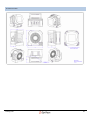
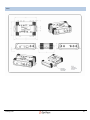
Tracking Tools software supports all current OptiTrack cameras and hardware devices. Camera selection is an important
part of the setup process. Please consult the guide below for detailed information about our cameras. If you need
assistance, please contact NaturalPoint, and our representatives will be more than happy to assist.
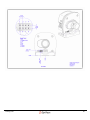
1.
2.
3.
4.
5.
6.
7.
8.
Allows cameras to switch between Infrared and Visible light for scene video.
Center imager only.
Using high power strobe mode, which requires an OptiHub.
Also accepts third party CS/C/M12 lenses.
Requires using the optional V120 sync break-out cable.
Hardware sync between multiple V120:Duo and V120:Trio devices is not supported.
S250e MJPEG frame rate is adjustable from 30 to 125fps.
With purchase of optional V120:Slim case.
Tracking Tools
28
IR Interference: Please ensure the capture volume setup area is free from external IR sources and reflections such as
sunlight, other lights which emit in the IR spectrum (incandescent, halogen, high pressure sodium), IR based devices, and
highly reflective materials. For IR sources and reflections which cannot be removed, the on-camera masking may be
used to block them. If you have questions regarding IR interference, please contact NaturalPoint support.
Flooring: Some environments use flooring that has a reflective coating, or is slightly flexible (such as hardwood). If
either of these applies, you should consider placing something to block reflections, or using heavy mats to pad any
movement in the floor.
Determining camera placement: In order to track markers, multiple OptiTrack cameras must be arranged to have
overlapping fields of view. This will create an area called a capture volume in which tracking can occur. Cameras should
be positioned such that a marker within any region of the capture volume will be visible to no less than two cameras,
and ideally more. Adjust camera placement and aiming so that the maximum overlap of camera fields of view occurs in
the area where most of the capture will take place. If you are mounting cameras on walls or truss, ensure you are using
mounting equipment that has sufficient ability to adjust camera positioning before mounting them. If you are using
tripods, ensure that they are placed in stable positions. Any movement of a camera or camera mounting hardware after
calibration will require recalibrating the volume. Please note that V100 and V100:R2 cameras have maximum mount
stud depths of .225”, and damage to the camera may occur if a longer stud is used.
Cabling: When placing cameras, keep in mind any restrictions that you may be subject to with cable lengths. Ethernet
cameras are subject to the limitations of the PoE and Ethernet communications standards (cables can be no longer than
100m). USB Cameras operating with OptiSync must have no more than 5m of cable and no extensions between the
camera and hub. The hub must be connected directly to the computer with no more than one 5m USB cable and up to
two 5m active USB extensions for a total of 15m between the computer and the hub. USB cameras using Wired Sync
instead of OptiSync may use cable extenders between the camera and the hub as long as the total cable length between
the computer and the camera does not exceed 20m. OptiHubs additionally require external power, and synchronization
cables must be connected between all OptiHubs.
USB Load Balancing: When connecting hubs to the computer, load balancing becomes important. Most computers
have several USB ports on the front and back, all of which go through two USB controllers. It is recommended
(especially in larger camera count systems) that you ensure the cameras are evenly split between the USB controllers to
best make use of the available bandwidth, as multiple cameras running in gray scale mode can easily overwhelm the
bus. The controller each camera is associated with can be viewed in the Project Explorer.
Network Setup: OptiTrack Ethernet cameras connect to the computer through a standard Ethernet port. A gigabit
(1000 Mb/second) Ethernet port is recommended in order to accommodate the high data rate of multiple cameras.
Camera network traffic should be segmented from the office or other local area network to avoid interference and
congestion. If the computer used for capture is connected to an existing network, then use a second Ethernet port or
add-on network card for connecting the computer to the camera network. For best performance, do not connect
devices other than the capture computer to the camera network. Add-on network cards should be installed if additional
network ports are required.
Tracking Tools
29
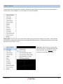
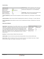
CAMERA CONTROLS
A context menu for changing camera settings is available by right clicking on a camera name in the project explorer, a
camera view in the 2D viewport, or on the camera icon in the 3D viewport.
Camera Name: The first line in the context menu displays the type and serial number of the camera. V100, V100:R2,
and V120:Slim cameras will indicate If they are equipped with Filter Switchers. V120:Duo and V120:Trio cameras will
denote if they are camera a, b, or c.
Video Type: Allows the user to set the video
type for the camera. Unsupported modes will
not be displayed. See the glossary for more
information on individual video types.
Tracking Tools
30
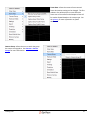
Frame Rate: Allows the camera frame rate and
frame decimations settings to be changed. The first
submenu line will display the current effective
frame rate of the camera and subsequent lines will
list modes allowed based on the camera type. See
the glossary for more information on frame
decimation.
Camera Group: Allows the user to switch the group
the camera is assigned to. See Cameras - Camera
Groups for more information.
Tracking Tools
31
Hardware Mask: Allows the user to perform camera
hardware mask operations. Block Visible Markers will mask
out all regions in a 2D camera view with detected markers.
Additionally, all current markers can be cleared. See the
glossary for more information on blocking.
Settings: Allows the user to adjust primary camera
control settings. See the glossary for definitions for all
camera settings.
Tracking Tools
32
Export: Allows the user to save the current 2D camera
frame as a bitmap.
Tracking: Allows single camera vector and projection
tracking options to be changed.
Tracking Tools
33
Projection: Allows the trackable image to be projected
onto the view pane using “Camera view”. The slider seen
in this screen shot has been deprecated and is not
available in Tracking Tools version 2.3.4 or later.
Frame Image Projection: Enables use of projection.
Orientation: Allows the user to rotate the orientation of
the 2D camera display on screen to a more natural viewing
angle. The angle slider allows the user to rotate the pane
in whole degree increments from -180 to 180.
Calculated Orientation: Sets the orientation of the camera
to display with the ground plane at the bottom of the view.
Clear Orientation: Resets pane orientation to 0 degrees.
Show Field of View: Toggles the camera field of view representation on and off in the 3D viewport.
Remove Camera: Removes the camera from Tracking Tools.
Identify: Causes the camera to blink in both the 2D and 3D viewports for easy identification.
Tracking Tools
34
CAMERA GROUPS
Cameras on the same system can be divided into different groups to create multiple capture volumes or increase the
effective frame rate. Simultaneous capture with separate groups is useful for the deployment of multiple tracking
volumes, such as pods in a shooting gallery. Additionally, camera groups can be used to achieve higher frame rates with
an interleaved configuration where cameras observing the same scene are divided into groups with different shutter
timing offsets.
Setting up camera groups:
To create a second camera group, right click on camera groups in the
project explorer, and select "Add Camera Group".
When the second camera group appears in the project explorer, you
can adjust the properties for the camera group by right clicking on it
and selecting properties. See Camera Group Properties for more
information.
To move a camera to a new camera group, right click on the camera in the project explorer, select the camera group
menu, then select "Move to Camera Group #" where # is the camera group you would like to move the device to.
When the camera has been successfully moved to the new camera group, it will appear in the project explorer under the
correct heading. The project explorer can be used to identify which cameras are placed in which group.
Tracking Tools
35
Once the cameras have been segmented into groups, you can select a color for
the cameras within a particular group. See Camera Group Properties for more
information on changing camera group visualization.
Interleaving:
Multiple camera groups observing the same capture volume can have their shutter times offset from one another to
create an interleaved volume with a higher frame rate. See Camera Group Properties for interleaving settings.
Example 1: Twelve V100R2 cameras could be interleaved into 2 groups of 6 cameras each with identical coverage
patterns. By offsetting the shutter time of one group by 5ms, the effective frame rate of the capture will be 200fps.
Each camera group must have its own master and its own synchronization chain to function properly.
Example 2: A volume with 24 S250e cameras can operate with one camera group featuring 24 cameras at 250fps, or you
can segment the cameras into two groups of 12 cameras each and offset the shutter of the second group 2000
microseconds to effectively capture at 500fps. Additionally, you could divide the volume further into 4 groups of 6
cameras each with offsets at 1000, 2000, and 3000 microseconds for an effective frame rate of 1000fps. The number of
groups involved in an offset depends on the number of cameras you have available.
If you are creating multiple groups of cameras, it is important to keep camera synchronization in mind. S250e cameras
will auto-handle synchronization offsets. V100, V100:R2, and V120:Slim cameras will need to have an individual sync
chain per camera group. See Synchronization for more information.
Tracking Tools
36
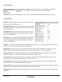
CAMERA GROUP PROPERT IES
Camera group properties allow the user to adjust settings for cameras on a group-wide basis. Any setting changed
within the camera group properties window will affect all cameras within that group.
The Camera Group Properties panel is divided into 4 sections which group
related settings together.
Camera Settings: Camera settings which will apply to all cameras within
the group.
Options: Visualization settings for the camera group.
Capture Volume: Visualization settings for the capture volume created
by the camera group.
Block Regions: Allows the user to specify the amount of over-masking to
apply when masking is used within the camera group.
Advanced: Advanced options which will apply to all cameras within the
group.
Tracking Tools
37
Camera Settings:
Exposure: Sets the exposure levels for all cameras within the camera group.
Valid range depends on cameras in group. See glossary for more information on
exposure.
Threshold: Sets the threshold for all cameras within the group. Valid range is 1255. See glossary for more information on threshold.
Illumination: Sets brightness level for IR LED rings on all cameras in the group.
Valid range is 0 (off) to 15 (full). See glossary for more information on
Illumination intensity .
Illumination Type: Sets IR LED rings to use either strobed or continuous IR mode. Availability of modes is based on
camera type. See glossary for more information on illumination type.
Video Type: Selects the on-camera image preprocessing mode. Availability of modes is dependent on camera type. See
glossary for more information on video modes.
Power Mode: Sets cameras to use low or high power IR LED mode. Available modes will depend on camera type and
whether the cameras are connected to an OptiHub. See glossary for more information on power modes.
Frame Rate: Sets cameras to operate at a specified frame rate. The rate will appear as either a percent or frames per
second count depending on camera type. See glossary for more information on Frame Rate.
Options:
Name: Sets the name for the selected camera group.
Camera Color: Sets the color for camera group members as they appear in the
3D viewport. Color values are input as standard RGB triplets.
Marker Color: Sets the color for point cloud markers generated by members of
the camera group. Color values are input as standard RGB triplets.
Visible Cameras: Selects whether cameras in the group are displayed in the viewport. Valid options are True (enabled)
(default), False (disabled).
Numeric LEDs: Selects whether cameras in the group are displayed in the viewport. Valid options are True (enabled)
(default), False (disabled).
Show Markers: Selects whether camera group 3D point cloud markers are displayed in the viewport. Valid options are
True (markers are visible) (default), False (markers are hidden).
Tracking Tools
38
Capture Volume Visualization:
Show Volume: Selects whether the capture volume is displayed in the viewport.
Valid options are True, False (default).
Camera FOV: Selects whether camera FOVs are displayed in the viewport.
Camera FOV accurately depicts the angle of view, while depth is artificially
capped. Actual depth may vary depending on the marker used. Valid options are
True (default), False.
Camera Overlap: Sets the minimum number of cameras which a region must be visible to in order for it to be
considered as part of the visualized capture volume. Higher numbers will tend to reduce the size of the visualized
capture volume. Valid range is 1 to 25 (default 3).
Volume Resolution: Sets the resolution of the capture volume visualization. A higher number represents a more
detailed visualization. Valid range is 1 to 120 (default 50).
Opacity: Sets the opacity of the volume visualization. A value of 1 is transparent and 100 is opaque. Valid range is 1 to
100 (default 100).
FOV Intensity: Sets the opacity of the FOV visualization. A higher value represents a more opaque volume visualization.
Valid range is 1 to 100 (default 50).
Block Regions:
Blocking Width (pixels): Sets the extra pixel coverage (width) for
masking visible markers when the block visible function is used. Valid
range is determined by the resolution of the cameras (default 4).
Blocking Height (pixels): Sets the extra pixel coverage (height) for masking visible markers when the block visible
function is used. Valid range is determined by the resolution of the cameras (default 4).
Block Visible: Updates the on-camera blocking mask to hide all objects visible to the camera.
Clear Blocking: Clears the entire blocking mask for all cameras.
Tracking Tools
39
Advanced:
Point Cloud: Specifies the engine used to solve the point cloud. Valid options
are Engine v1.0, Engine v2.0 (default). See glossary for more information on the
differences between Engine V1.0 and Engine V2.0.
Precision Cap (bytes): Sets the upper limit for the amount of data transmitted
by each camera in precision mode. This setting is used to prevent instability
caused by large spikes in the data rate. Default value is 20000.
Interleave Group: Used for setting up interleaved groups of cameras with identical frame rates and offset shutters to
effectively increase their recording frame rate. Valid options are True, False (default). See Camera Groups for more
information on interleaving.
Shutter Offset: Sets the offset in microseconds for the camera group when using camera group interleaving. Valid
range is dependent on capture frame rate. See Camera Groups for more information on interleaving.
Tracking Tools
40
SYNCHRONIZATION
Once set up, cameras must be synchronized in order to align their exposure timing. There are two primary methods of
synchronizing USB cameras - OptiSync and Wired Sync. S250E cameras use an Ethernet based synchronization.
Note: For general use, camera synchronization should be automatic once all the required cables have been connected.
The additional detail provided in this section is intended to provide assistance with custom needs such as shutter glasses
or force plate synchronization.
OptiSync: OptiSync is NaturalPoint’s custom synchronization that utilizes OptiHubs to control the synchronization of the
cameras. No extra sync cable is required. OptiSync is only available when using V100R2 cameras connected to
OptiHubs. Multiple OptiHubs in a camera group must be connected by a hub to hub sync cable in daisy chain fashion.
While technically possible, the use of mixed Wired Sync and OptiSync configurations are not officially supported.
Wired Sync: Wired sync provides camera to camera sync using an extra set of cables in a daisy chain arrangement in
addition to the USB cables. The Y-shaped sync adapter is required in addition to sync cables. Wired Sync should be used
if one or more non-V100:R2 cameras are present or if any of the cameras are not plugged into OptiHubs. Wired Sync
can be used instead of OptiSync if desired for V100:R2 cameras.
Wired sync is available for Flex:V100, Slim:V100, V100:R2, and V120:Slim cameras. Wired sync with an OptiHub in the
chain requires the master OptiHub to be at the start of the sync chain. If using the external trigger input capabilities of
an OptiHub, then the first camera in the daisy-chain must be connected to the Hub Sync Out jack of the OptiHub. V100
cameras can be used in the same Wired Sync chain with V100:R2 cameras. All other cameras (C120, V120:Slim) cannot
be mixed with other camera types.
The Synchronization Pane in Tracking Tools allows the user to select
between common usage scenarios. The "Default Synchronization" setting
allows the cameras to auto-detect their synchronization mode (Wired
Sync, OptiSync, or Ethernet Sync) and has no external synchronization
options enabled. If you are planning on synchronizing the system with an
externally-provided signal, you must have an OptiHub, an I/O-X Sync Box
(for V120:Duo or V:120 Trio systems), or Ethernet eSync. You can then
select "Custom Synchronization" or "Shutter Goggles Synchronization"
Tracking Tools
41
Shutter Goggles Synchronization:
Type: Sets the type of goggles to synchronize to. Valid options are:
Stereographics, NuVision 60GX, NuVision APG6000.
Sync Mode: Selects between OptiSync and Wired Sync. The correct mode
must be selected based on camera setup.
Video Frame Rate: Selects the frame rate that the reference video will be
shown at. User must select the correct frame rate based upon what is
encoded by the video synchronization input signal to the OptiHub.
Advanced Options: Advanced options were available in this pane in
Tracking Tools 2.3.3 and earlier. These options should not be adjusted,
and have been deprecated in newer versions of Tracking Tools.
Tracking Tools
42
Custom Synchronization:
Sync Mode: Selects between OptiSync and Wired Sync.
Internal Sync Freq (Hz): Controls the frequency in Hertz (Hz) of the
OptiHub's internal sync generator. This option is only valid if Sync Input:
Source is selected to be internal sync. Valid range is 8 to 100.
Global Sync Offset (us): Controls the delay in microseconds (us)
between the chosen sync source and when the cameras are actually told
to expose. This is a global system delay that is independent of, and in
addition to, an individual camera's exposure delay setting. Valid range is
0 to 65862us.
Source: Selects a source for the sync trigger. See glossary for more
information on Sync Sources.
USB Sync-In Control: Only available if Source is set to USB. Allows the
user to allow or block trigger events generated by the internal sync control. This option has been deprecated for use in
the GUI. Valid options are: Gate-Open and Gate-Closed.
External Input Trigger: Only available if source is set to External Sync. Selects the type of input source. See glossary for
more information on External Sync Signals.
Input Divider: Only available if Source is set to External Sync. Allows a triggering rate compatible with the camera
frame rate to be derived from higher frequency input signals (e.g. 300Hz decimated down to 100Hz for use with a
V100:R2 camera). Valid range is 1 (no decimation) to 15 (every 15th trigger signal generates a frame).
Pulse Type: Selects the condition and timing for the pulse to be sent out over the External Sync Out jack. See glossary
for more information on Sync Pulses.
Polarity: Selects output polarity of External Sync Out signal. Valid options are: Active High, Active Low.
Take Snapshot: Only available if Source is set to USB. Used to generate a one-time trigger event which will cause the
cameras to expose and transfer a single frame.
Tracking Tools
43
CHAPTER 3: CALIBRATION
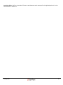
THREE MARKER
Three marker calibration is the preferred method of capture volume calibration. It provides greater system accuracy
and allows for more flexible camera positioning. This calibration method requires the OptiWand, and should be used if
you are running any version of Tracking Tools 2.2.0 or higher.
The three marker wand calibration pane is divided into 5 sections to organize the
settings.
Solver Options: Contains base options that are used for solving the calibration.
Data Acquisition: Contains settings that will affect how Tracking Tools detects the
wand.
Display options: Contains options to control visualizations during calibration.
Advanced Options: Contains options that can affect the overall quality and speed of the
calibration. Options within this submenu should only be changed under advisement of
technical support.
Wand Acquisition: Contains constraints for detecting markers on the wand.
Tracking Tools
44
Solver Options:
Quality: Selects the quality level at which the calibration will run. Quality
directly affects the number of samples used in solving the calibration.
Indirectly, increasing the quality of calibration will increase the amount of
time required to solve. See Wanding and Calculating for tips on selecting
a quality. Valid options are: Low, Medium (default), High, Very High.
Calibration Type: Selects the calibration type. See the glossary for more
information on Calibration Type. Valid options are: Full (Default), Refine, Visualize Only.
Solver Scope: Selects the features of each camera to adjust during solving. Extrinsic refers to camera orientation and
position, Intrinsic refers to lens distortion. Valid options are: All (Default), Extrinsic + Focal, Extrinsic Only, Intrinsic Only.
OptiWand: Selects the size of the wand used for calibrating. Valid options are: Small (250mm), Medium (400mm)
(default), Large (500mm), Custom.
Wand Length (mm): Adjustable constraint for a custom OptiWand that allows the user to define the distance in
millimeters between the two outer posts of your wand.
Center Distance (mm): Adjustable constraint for a custom OptiWand that allows the user to define the distance in
millimeters between the outer post and the center post (use the shorter of the two center offset distances).
Data Acquisition:
Sampling Speed %: The sampling speed, as a percent of the total frame
rate of the cameras, which is used for calibration. Valid range is 1 to 100,
Default 80.
Min Camera Coverage %: The minimum number of cameras, as a percent
of the total number of cameras in the group, which are required to see a marker to consider the sample valid. The
number of cameras is always rounded up. Valid range is 1-100. Default 20.
Stationary markers: Instructs the software to automatically block stationary markers. Markers are considered
stationary if their centers are in one position for more than a few seconds. Valid options are Block (default), unblocked.
Camera Group: Selects the camera group to be calibrated. Valid options are all currently assigned camera groups.
Tracking Tools
45
Display Options:
Solver Visualizations: Selects whether solver visualizations should be
displayed during wanding and calculations. In some cases, disabling this
can free resources to speed calibration solving. Valid options are: Show
(Default), Hide.
Lens Distortion: Selects whether lens distortion solver visualizations on
the 2D multi camera view should be displayed during calculations. Valid
options are: Show (Default), Hide.
Cameras: Selects whether camera adjustment visualizations in the 3D perspective view screen should be visible during
calculations. Valid options are: Show (Default), Hide.
Wanding Projection: Selects whether wand visualizations in the 3D perspective view should be visible during wanding.
Valid options are: Show (Default), Hide.
Projection Error: Selects whether wand and marker projection and visualization should be visible in the 3D projection
view during calculations. Valid options are: Show (Default), Hide.
Residual Error (mm): Sets the threshold for individual marker display in the projection error display. Any markers with
a residual below this number will display blue, any markers with a residual above this number will display red. Default is
6.00
Wand Error (mm): Sets the threshold for wand measurement error in the projection error display. Any wand samples
that are either larger or smaller than the expected size by a minimum of this value in millimeters will display as red.
Wand samples that are within this value are displayed as blue. Default is 8.00.
Sample Spacing: Sets the density of samples in the projection error display. The display will include every sample with a
value of 1, and every nth sample if it is raised higher. Valid range is whole numbers between 1 and 10. Default is 1.
Tracking Tools
46
Advanced Options:
Lens Type: Allows a particular type of lens to be specified for all cameras
within the volume. Valid options vary depending on the camera used.
Default selection is Auto-Select, which will attempt to identify the type of
lens used based on calibration data.
Single Focal: Requires solving of a single focal length instead of the
default behavior of solving horizontal and vertical focal lengths
individually. Can be enabled to help the solver in difficult situations. Valid
options are: True, False (Default).
Lock Principal Point: Requires the solver to assume that the camera's lens is perfectly centered over the image sensor.
Setting this can sometimes assist in difficult calibration calculations. Valid options are: True, False (Default).
Minimize Deviation: Sets the solver to include the Standard Deviation along with the residual and the wand length as
constraints for solving the calibration. This option has been deprecated, and is not in versions beyond 2.3.4. Valid
options are: True, False (Default).
Wand Constraint: Tells the solver to use the wand length to scale the volume based on the wanding data. Valid options
are: Disabled, Initial Fit, Always (Default).
3rd Order Intrinsics: Enables a more complex model for lens distortion calculation, but adds overhead to the calibration
calculations and will likely cause a slowdown in the process. This option should be enabled if you feel you need to try to
get better calibration results. Valid options are: True, False (Default).
Solver Thread: Allows the user to set the priority of the solver thread. This can be adjusted if the solver is causing too
much latency in other running programs on the computer. Valid options are: Highest Priority (Default), High Priority,
Normal Priority.
Apply Result: Selects whether the calibration will be applied continuously throughout the calculation, or if it will be
applied only when you elect to apply the result. Valid options are: Continuous (Default), Apply Button.
Tracking Tools
47
Wand Acquisition:
Imager Border: The size, in pixels, of the dead zone around the camera
imager. Any wand samples detected partially or wholly within the border
region are ignored. Default is 16.
Min Object Size (Pixels): The minimum number of pixels a wand marker
must be comprised of before being counted as valid during calibration.
Default is 2.
Max Object Size (Pixels): The maximum number of pixels a wand marker may be comprised of before not being
counted as valid during calibration. Default is 500.
Min Feature Size (Pixels): The minimum number of pixels that must exist between the two outer markers of the wand
for the sample to be considered valid for calibration. Default is 28.
Min Camera Distance (mm): The minimum distance that the wand must be from the camera in millimeters before it will
be accepted as a valid sample. Default is 300.
Min Object Roundness: Sets the sensitivity of the roundness filter during calibration. See glossary for more
information. Valid range is between 0 and 1 (Default 0.8)
Tracking Tools
48
ONE MARKER CALIBRATION
One marker calibration is a method available for use in older systems, and should only be used if access to the newer,
more flexible and more accurate three marker calibration is not available.
The one marker calibration wizard consists of four buttons, a progress bar, and two
sections of options to organize the interface into easily usable sections.
Start Wanding: This button starts the calibration wanding process, and instructs
Tracking Tools to look for the marker.
Reset: This button stops the calibration process without calculating the results. This
button is only available during wanding.
Status Bar: This bar is active during the wanding process and shows the amount of
wanding time that has elapsed. The bar will turn from gray to green as samples are
collected, and will be fully green when there are sufficient samples.
Calibration Options: Contains options for to the calibration methods and environment.
Wand Filtering: Contains options to filter markers by quality.
Calculate: Starts the solver calculation process after sufficient wanding samples have
been gathered. This button will remain grayed out until there are enough samples to
calculate a result.
Apply Result: Applies the solved calibration to the cameras and capture volume. This
button will remain grayed out until calculation is complete.
Tracking Tools
49
Calibration Options:
Calibration Accuracy: Sets the complexity of the calibration solver
calculations. Lower complexity will result in a lower quality calibration,
but a significantly faster solve. Valid options are: Low (Default), Medium,
High, Very High.
Wanding Time: Selects the amount of time in seconds allotted for wanding. Default is 10.
Approximate Volume: Selects the size of the capture volume that is being wanded. This option does not restrict the
volume size, but is used to constrain the solver, and should be set as close to the real volume size as possible. Valid
options are: 1 Cubic Meter, 3 Cubic Meters (default), 6 Cubic Meters.
Min Camera Coverage: Selects the minimum number of cameras that must see a marker for it to be considered valid to
take a sample. Valid range is 2 to the number of cameras you are calibrating. Default is 2.
Selection: Selects how samples are selected from the wanding data. This option has been deprecated, and the only
valid option is Distributed.
Camera Group: Selects the camera group to be calibrated. Valid options are all currently assigned camera groups.
Wand Filtering:
Filter Type: Selects the type of 2D marker filtering use by Tracking Tools.
Valid Options are None, Size and Roundness (default).
Min Marker Size: The minimum number of pixels a wand marker must
contain to be accepted during calibration. Setting this option to a value
higher than Max Marker Size will result in no markers considered valid.
This option is ignored if size filtering is disabled. Default is 8.
Max Marker Size: The maximum number of pixels a wand marker may consist of. Setting this option lower than Min
Marker Size will result in no markers considered valid. This option is ignored if size filtering is disabled. Default is 150.
Min Roundness: Sets the sensitivity of the roundness filter during wanding. See glossary for more information. Valid
range is between 0 and 1 (default 0.8).
Tracking Tools
50
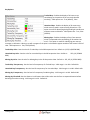
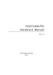
WANDING AND CALCULATING
Wanding is the primary method of calibrating a capture volume in the Tracking Tools software. A one or three marker
wand is waved through the entire capture volume while the cameras observe it and take samples. Once wanding data
has been collected, it is then used to solve the physical position (extrinsic) and lens characteristics (intrinsic) of the
cameras. Proper wanding technique is essential to a good calibration.
The information in this section is primarily for wanding with the Three Marker Calibration method.
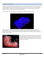
When wanding, move the wand slowly across the entire capture volume , covering as much space as possible for
sufficient sampling. For best results, wand the volume evenly and comprehensively throughout the space. See the
image above for an example of proper wanding for a large motion capture volume. Your volume may differ depending
on camera setup and aiming.
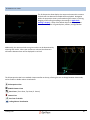
After wanding through all areas of the volume, consult the 2D Multi
Camera view to evaluate individual camera coverage. Each camera
should be thoroughly covered with wand samples. If there are any
large gaps, attempt to focus wanding on those to increase coverage,
as in the pictures to the left.
Tracking Tools
51
If a camera will not record samples while wanding, even though the wand is visible in its view, consult the 2D Multi
Camera view to see if other cameras are also detecting the wand. If the wand does not appear on any other cameras,
the area will not calibrate due to lack of coverage. If the markers show up on at least two other cameras, continue
wanding, but adjust the path and angle of the wand to give the camera different perspectives to record the data.
Cameras will only record samples if the wand is within a specific range of angles in relation to the camera. If samples are
not being collected, then try to adjust the wanding path and angle. If a region of the desired capture volume will not
record samples after taking all of the steps above, cancel the calibration and re-aim the cameras to obtain better camera
overlap for that area.
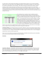
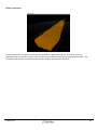
After wanding has been completed, check the calibration panel for
feedback on the number of samples collected. The window will give a
Sufficiency rating which defines whether sufficient samples were recorded
to meet the minimum requirements for low, medium, high, or very high
quality. The rating only takes into account minimum samples, so a higher
sample quantity should be used for larger volumes. A 6 camera system
will calibrate properly with an average of 1000 samples per camera. For
higher camera counts the average number of samples per camera should
be about 200-225 multiplied by the number of cameras (1600 per camera
for an 8 camera system, 3200-3600 per camera for a 16 camera system).
If there are any cameras with a significantly lower number of samples than the rest, as camera two has in this example
picture, attempt to focus more wanding on that camera to bring up the sample count.
One Marker Wanding: The wanding technique for One marker calibration is similar to Three Marker wanding, however
the visualizations are different. During the wanding process, green lines connecting the samples taken will be displayed
in each 2D camera view. Attempt to evenly distribute the sample coverage for all cameras since it can be challenging to
entirely fill each camera view with the green lines.
Note: The one marker calibration approach has been deprecated, and should not be used unless you are restricted by
your license to a version that does not offer three marker calibration.
Calculation:
One Marker Calibration: The One Marker calibration algorithm runs a single calculation phase and will return results
quickly. Once wanding is complete then solving can be started by pressing the “Calculate” button. When the dialog
shown above appears, press the “Apply Result” button to begin using the solved calibration. An opportunity will be
given to save the wanding timeline for future use. This is highly recommended.
Tracking Tools
52
Three Marker Calibration: Three marker calibration goes through multiple phases, and can be adjusted dynamically,
allowing the user significant control over the time required and final overall precision of the system. Immediately after
clicking calculate, the samples window will turn into the solver window. It will display the solver stage at the top,
followed by the overall result rating and the overall quality selection. The overall result rating is the lowest rating of any
one camera in the volume. The overall quality selection shows the current solver quality.
The solver window will display a quality rating for all cameras as well as the global average and the wand average.
Additionally, it will display the calculated focal length, standard deviation, and mean error for each. The quality rating is
directly related to the mean error, and will update accordingly. Valid quality ratings are (on order from worst to best):
Poor, Fair, Good, Great, Excellent, Exceptional.
The calculation process begins with automated refinement and
optimization phases. The first phase is "Refine initial solution", followed
by the "Global Optimization: Initial" phase, and finally the "Global
Optimization: Final" phase. Each successive phase will solve the
calibration of the system in greater detail, and the system will move from
one phase to the next automatically. Once the solver reaches the final
optimization phase, it will continue to refine the solution until the user
opts to apply the result. As the final optimization continues, the overall
quality of the calibration and accuracy of the system will improve.
You should allow each camera to reach "Good" as a minimum baseline for
accurate motion tracking, though it is recommended to continue until
each reaches "Excellent" or above. Once each camera reaches
"Exceptional", however, the solver will hit a point of diminishing returns as
it takes successively longer to receive smaller gains in calibration quality.
For high-precision calibrations, aim for a mean error of 0.145 or lower on
each camera.
Tracking Tools
53
TIP: To maximize sample count and calibration quality, increase the
quality setting incrementally during the final optimization phase.
Start on medium quality.
Once each camera reaches excellent or higher, move to high.
Once each camera reaches excellent or higher, move to very high.
This technique can speed up the calibration process and reveal problems
with wanding more quickly.
Note: Occasionally a system may reach exceptional very quickly on
medium and very high, but may stall out at great on high. This indicates a
sampling error. If this situation is encountered, cancel the calibration and
re-wand.
Clicking "Apply results" will launch a summary window to
review calibration results and additional options.
Apply Suggested Residual: This option will allow Tracking
Tools to set the residual for the calibrated cameras according
to the residual discovered during calibration. This is checked
by default and should only be unchecked if there are preexisting settings that you wish to override this.
Apply and Refine: This option will apply the calibration to the
capture volume while also continuing to further refine the
calibration in the background as you use the system.
Apply: This option will simply apply the results and end further
calibration calculation.
Cancel: Exits calibration without applying the results.
After applying the results, an option will be presented to save the wanding timeline. This is suggested, but not required.
Wanding timeline files can be used by NaturalPoint support to help troubleshoot any potential issues in data while using
the applied calibration.
Tracking Tools
54
GROUND PLANE
Once the cameras have been calibrated, a ground plane must be used to align their 3D coordinate system with the
physical capture volume. The ground plane is an L-shaped bracket with Markers attached at specific positions to form a
90 degree triangle.
The center of the marker in the corner of the ground plane represents the origin of the coordinate plane.
Long Arm: 400mm, points down the positive Z axis.
Short Arm: 300mm, points down the negative X axis (right handed coordinate plane (default)).
Top of Plane: Upwards from the plane (marker side) points down the positive Y axis.
The coordinate plane generated by the ground plane is right handed by default. To switch to a left handed coordinate
plane, see the option in "Application Settings - Options".
Tracking Tools
55
Three Marker Calibration:
Once the volume is calibrated, use the calibration square to set
the coordinate system. The vertical offset is preset to 53mm,
and indicates the distance between the ground and the center of
the markers. This allows the ground plane to sit directly on the
ground and have the ground act as the X-Z plane. This should
only be changed if the ground plane is not placed on the surface
that the origin should be on, such as if it is on a tripod. In this
case, measure the distance between the center of the markers
and the X-Z plane and enter the value in millimeters. Once the
desired vertical offset has been set, click “Set Ground Plane”
One Marker Calibration:
Setting the 1 ground plane during one marker calibration sets the volume
scaling in addition to aligning the coordinate system. When setting the
ground plane, ensure that the measurement between the two markers on
the long side is accurate, then press "Set Ground Plane".
Capture Volume Translation:
The Capture Volume Translation window allows the origin of the capture
volume to be moved using an offset for any of the three axes. Negative
numbers are valid for use within these fields.
Tracking Tools
56
POINT CLOUD PROPERTIES
The point cloud properties pane allows solving and 3D point cloud reconstruction settings to be changed. Point cloud
properties are set for camera groups and can be accessed by right clicking on a camera group and selecting properties.
Systems with multiple camera groups can have separate solving properties for each group.
The point cloud properties pane is divided into 5 sections to help separate
the available options into easily recognizable clusters.
Options: General point cloud solving options.
Advanced Options: Additional Options for point cloud solving.
2D Object Filter: Options for filtering 2D data before performing 3D
reconstruction. These options can be used to filter out unwanted objects
and prevent them from contributing to point cloud reconstruction.
Reconstruction Bounds: Contains options for setting point cloud
reconstruction boundaries. Any markers that fall outside of the
boundaries will not be reconstructed.
Enable Point Could Reconstruction: This checkbox allows point cloud
reconstruction to be turned on or off. Unchecking this box will prevent
the point cloud from being calculated, and can be used to improve
performance on machines that experience issues with real time
operation.
Tracking Tools
57
Options:
Residual: The maximum distance which intersecting camera rays
may pass from each other and still be used to construct a valid
3D marker. The value is specified in millimeters. The default is
determined during calibration. See the glossary for more
information on residual.
Minimum angle: The minimum number of degrees (from the
marker's point of view) that must separate two cameras to
consider the camera's rays valid for marker reconstruction.
Default is 2. Maximum value is 180.
Minimum Rays: The minimum number of cameras that must see the marker within the bounds of the Residual,
Minimum Angle, Minimum Ray Length, and Maximum Ray Length to determine if a marker is valid for 3D reconstruction.
Default is 2. Valid range is from 2 to the total number of cameras.
Minimum Ray Length: The minimum distance a marker can be from the camera and still be used for 3D reconstruction.
The value is specified in meters. Default is .20.
Maximum Ray Length: The maximum distance a marker can be from the camera and still be used for 3D reconstruction.
The value is specified in meters. Default is 10.
Pixel Gutter: Pixel Gutter establishes a dead zone, measured in pixels, around the edge of the camera frame where 2D
markers will be considered invalid for reconstruction. Use in cases of lens edge distortion. Default is 0.
Maximum 2D Objects: The maximum number of 2D markers per camera that will be used to reconstruct the point
cloud. Valid range is 0 to 512. Default is 100.
Maximum calculation time: Maximum amount of time Tracking Tools will spend attempting to reconstruct the point
cloud per frame per camera group. The value is specified in milliseconds. Default is 50.
Marker Size:
Marker Diameter: Select whether Tracking Tools will attempt to
determine the marker size. Valid options are Set Diameter,
Calculate (default).
Diameter (mm): If Marker Diameter is set to "Set Diameter" then the Diameter field will appear. This field allows a predetermined marker size (in millimeters) to be entered for use in calculating the point cloud. This setting is ignored if
Marker Diameter is set to "Calculate". Default is 12.
Tracking Tools
58
Advanced Options:
Note: Ray ranking has been deprecated, and does not appear in versions newer than 2.4.4.
Ray Ranking: Selects whether ray ranking is enabled. See the
glossary for more information on Ray Ranking. Valid options are
True (enabled), False (disabled) (default).
Minimum Ray Count: Sets the minimum number of rays used to create a 3D point before ray ranking is triggered for
that point. This setting is ignored if Ray Ranking is set to "False". Default is 4.
2D Object Filter:
Filter Type: Selects the type of 2D marker filtering use by
Tracking Tools. Valid Options are None, Size and Roundness
(default).
Min Marker Size: The minimum number of pixels a marker must
be comprised of to be considered a valid marker. Setting this option to a value higher than Max Marker Size will result in
no markers considered valid. This option is ignored if size filtering is disabled. Default is 4.
Max Marker Size: The maximum number of pixels a marker can be comprised of to be considered a valid marker.
Setting this option lower than Min Marker Size will result in no markers considered valid. This option is ignored if size
filtering is disabled. Default is 500.
Min Roundness: Sets the sensitivity of the roundness filter. See glossary for more information. Valid range is between
0 and 1 (default 0.6).
Tracking Tools
59
Reconstruction Bounds:
Bound Reconstruction: Selects whether reconstruction
bounding is enabled. See glossary for more information. Valid
options are True (enabled), False (disabled) (default).
Visible Bounds: Select whether the reconstruction bounds are
displayed in the viewport. This setting is ignored if Bound
Reconstruction is set to "False". Valid options are True (visible),
False (invisible) (default).
[Minimum/Maximum] [Axis] (meters): Sets the distance from the origin on each axis (in meters) for each of the 6
reconstruction bounds. See glossary for more information. Defaults are 6 for maximums, -6 for minimums.
Tracking Tools
60
CHAPTER 4: VISUALIZATION
APPLICATION SETTINGS - DISPLAY
The display tab in the application settings pane contains options for adjusting 2D and 3D visualization.
The display tab options are broken into 5 sections to organize options into
easily identifiable groups.
2D Display Options: Contains options for status overlay and marker display
within individual camera 2D viewports.
Distortion Map: Contains options for enabling and displaying camera lens
distortion characteristics.
Multi-Camera 2D Display: Contains rendering options for the pane which
displays multiple 2D viewport cameras.
3D Display Options: Contains visualization options for the 3D viewports.
Ray Options: Contains options for rendering camera rays.
Tracking Tools
61
2D Display Options:
Camera Info Overlay: Enables text overlay of information on the 2D Multi
Camera view panes. Valid options are: True (default), False.
Verbose Camera Info: Enables the overlay of additional information on the 2D
Multi Camera view panes including settings, current time, individual camera
data rate, Frame ID, current display rate, and marker count. This option is
ignored if Camera Info Overlay is set to false. Valid options are: True, False
(default).
Camera Reticle: Enables the crosshair feature. See 2D Multi Camera View for
more information. Valid options are: True, False (default).
Backproject Markers: Enables 2D Multi Camera view markers to have
individual crosshairs over them when they are selected in the 3D Perspective
view. The crosshairs are displayed at the location where the 2D marker is
expected based on the position of the related marker in 3D space. Crosshairs
that are not directly over the marker tend to indicate occlusion or poor camera
calibration. Valid options are: True (default), False
Object Filter: Enables display of filtering information. Valid options are: True (default), False.
Object Centroids: Enables the display of the marker centroid as a crosshair. Valid options are: True, False (default).
Object Extents: Enables the visualization of a rectangular box around the object, sized to the horizontal and vertical
region the object occupies (after threshold is applied). Valid options are: True, False (default).
Object Coordinates: Enables the display of the object centroid coordinates to 1/100th of a pixel. Valid options are:
True, False (default)
Object Aspect Ratio: Displays the ratio of object length to object height as a decimal, accurate to .01 pixel. Valid
options are: True, False (default).
Object Size: Displays the area of the object in pixels, accurate to .01 pixel. Valid options are: True, False (default).
Object Roundness: Displays the roundness of an object. A value of 1 indicates maximum roundness, while a value of 0
indicates no roundness.
Object Label: Displays the object label assigned by the software to facilitate tracking them from frame to frame. Valid
options are: True, False (default).
Pixel Inspection: Enables display of information about the camera pixel currently pointed to by the mouse. Valid
options are: True, False (default).
Visual FPS Target: Sets a maximum display rate for the 2D camera view. Default is 65.
Background Color: Selects the color to display in the viewport between camera panes. Default is 240; 240; 240 (FEFEFE
RGB).
Tracking Tools
62
Distortion Map:
Show Distortion: Enables visualization of the camera lens
distortion map over the individual camera in the 2D Multi
Camera View. Valid options are: True, False (default)
Overlay Color: Selects the color of the lens distortion map
display. Default is 204; 255; 102 (CCFF66 RGB).
Overlay Transparency: Selects the level of transparency for the lens distortion map. Valid range is: 5 to 100. Default
10.
Overlay Resolution: Selects the level of detail for displaying the lens distortion. Valid range is: 5 to 100. Default 40.
Show as Predistortion: Selects whether the map is shown as predistorted or distorted. Valid options are True, False
(default).
Multi-Camera 2D Display:
Display Mode: Toggles between Frame Buffer, Marker Centers, and Automatic
LOD modes. Frame Buffer mode pushes the entire camera frame to the video
card for scaling and display. Marker centers mode merely defines a white
circle of the rough size and shape of the marker as it would appear, and is
significantly less hardware intensive. Automatic LOD switches between Frame
Buffer mode and Marker Centers mode depending on distance. Default is
Automatic LOD.
Pane Gap: The distance between 2D Multi View camera panes.
LOD Threshold: The size at which the system switches between Marker Centers and Frame Buffer mode.
Raster Priority: Defines the update rate for the camera pixel data shown in the 2D Multi Camera views. A higher
priority indicates a higher rate of update. Valid range is 1 to 6. Default 1.
Tracking Tools
63
3D Display Options:
Camera Names: Enables the floating camera model, serial,
and master/slave status above and below camera objects.
Valid options are: True (default), False.
Text Size: Adjusts the size of the camera name text. Valid
range is: 10-300. Default 60.
Sync Cable: Enables the display of a virtual sync cable
between cameras. Valid options are: True, False (default).
Solid Cameras: Disables camera object transparency in the
3D Perspective view. Valid options are True (default), False.
Marker History: Enables the display of individual marker history trails within Tracking Tools and allows a visual history
to be kept of previous locations. Valid options are: True (default), False.
Selected History Only: Restricts the marker history to selected markers only, and prevents the display of unselected
marker history. Valid options are: True (default), False.
Show Marker Labels: Enables the display of the individual marker labels in the 3D Perspective view. Valid options are:
True, False (default).
Display mode: Enables the display of camera numbers projected onto the camera face in the 3D Perspective View.
Valid options are: Black, Camera Number (default).
Background Color: Selects the background color displayed in the 3D Perspective view. Default is
RGB).
0; 0; 0 (000000
Grid Color: Selects the color of the ground plane coordinate grid in the 3D Perspective view. Default is: 255; 255; 255
(FFFFFF RGB).
Grid Transparency: Selects the level of transparency applied to the ground plane coordinate grid in the 3D Perspective
view. Valid range is 0 to 100. Default 100.
Grid Size: Selects the area covered by the ground plane coordinate grid in the 3D Perspective view. Valid range is 1 to
100. Default 30.
Tracking Tools
64
Ray Options:
Tracked Rays: Enables the display of all camera rays
contributing to the position of the currently selected
marker(s). Valid options are: True (default), False.
Untracked Rays: Enables the display of all camera rays
which were not used in reconstructing 3D markers. This
option is useful for identifying background light interference
and poor camera calibration. Valid options are: True, False
(default).
Missing Rays: Enables the display of rays from cameras
which are expected to be contributing to 3D markers but
aren’t. This option is useful for identifying poor camera
coverage or calibration. Missing rays will not appear if the point is calculated to appear outside of the camera's field of
view. Valid options are: True, False (default).
Tracked Ray Color: Sets the color for Tracked Rays in the 3D Perspective View. Default is: 0; 255; 0 (00FF00 RGB).
Untracked Ray Color: Sets the color for untracked Rays in the 3D Perspective View. Default is:
RGB).
255; 0; 0 (FF0000
Missing Ray Color: Sets the color for Missing Rays in the 3D Perspective View. Default is: 255; 255; 0 (FFFF00 RGB).
Tracked Ray Transparency: Sets the level of transparency for Tracked Rays. Valid range is 1 to 100. Default 80.
Untracked Ray Transparency: Sets the level of transparency for Untracked Rays. Valid range is 1 to 100. Default 100.
Missing Ray Transparency: Sets the level of transparency for Missing Rays. Valid range is 1 to 100. Default 100.
Missing Ray Threshold: Sets the distance in millimeters that a 2D marker must be from an expected location before
declaring the marker missing. Valid range is 1 to 20. Default 10.
Tracking Tools
65
3D PERSPECTIVE VIEW
The 3D Perspective View displays the capture volume and its contents
for both real time data and recorded timeline playback. Navigation
within the perspective view is performed using the mouse, by clicking,
dragging, and scrolling (according to the settings in Application
Settings – Display). Some of the default objects in the perspective
view are cameras, the X-Z ground plane, markers, and rigid bodies.
Additionally, the cameras which see a given marker can be determined by
selecting that marker. When two markers are selected, the distance in
millimeters between them will be displayed in real time.
The 3D perspective view has a standard viewport toolbar at the top, allowing the user to change between view modes,
and to enable or disable volume visualizations:
3D Perspective View
2D Multi Camera View
Other Views: (Front View, Top View, Et. Cetera)
Camera View
View From Trackable
Tracking Volume Visualization
Tracking Tools
66
Volume Visualization:
The size and position of a capture volume can be estimated for a given camera group. Settings to adjust the
visualization such as resolution, camera count, and opacity can be found in the camera group properties panel. The
visualization and field of view color will match the color used for the cameras in the group.
Tracking Tools
67
2D MULTI CAMERA VIEW
The 2D Multi Camera View displays 2D image data from one or more cameras. The 2D multi camera view can be a
powerful tool in aiming and troubleshooting.
Click the 2D Multi Camera view icon (
) in the viewport to convert it to a 2D multi camera view. Additionally, this
icon can be used to zoom out and display the 2D views for all camera views evenly.
Each camera appears as a pane within the viewport window. The pane will display
information such as the mode, camera type and serial number, camera number, sync
type, and error messages. If an object in the camera pane has been identified as not
being a valid marker, a red X will be displayed over it along with an explanation of
why it was rejected (in this case, size filter).
Navigating the 2D Multi Camera view can be accomplished with the buttons defined in Application Settings - Options.
By default, the left click will draw masking (Blocking) on the camera, while the middle button will pan the cameras for
more precise aiming. Additionally, the scroll wheel will zoom in and out, allowing the user to get close up views of
individual camera pixels.
Toolbar:
The viewport toolbar contains many 2D Multi Camera view specific options for configuring the viewport. The first four
options affect the size of the camera view panes as they display in the viewport:
Sets all 2D camera views to one half their actual size (in pixels)
Sets all 2D camera views to display as their actual size (in pixels)
Sets all 2D camera views to double their actual size (in pixels)
Auto scales all 2D cameras to fit into the viewport window.
Tracking Tools
68
The toolbar also contains five options for adjusting the blocking mask features of Tracking Tools individually:
Block all markers visible in all cameras
Remove all blocking masks from all cameras
Draw a rectangular blocking region
Draw a circular blocking region
Draw a freehand blocking region
Finally, the toolbar contains an icon to enable a virtual camera reticle to display on the pane:
Enable Crosshairs
Tracking Tools
69
FRAME INFO
The Frame Info pane provides real time information about the point cloud.
Camera FPS: Current capture rate of the cameras in frames per second.
Display FPS: Current display rate of the application in frames per second.
2D Markers: Total number of individual 2D markers seen by all cameras
before point cloud reconstruction.
3D Markers: Total number of 3D markers in the point cloud.
Trackables: The number of defined rigid bodies currently being tracked.
Tracking Tools
70
CHAPTER 5: SOFTWARE USAGE
PROJECT FILES
Project files are a convenient way of storing and loading capture sessions. Project files store the camera calibration,
defined rigid bodies, and application settings in a single .ttp file. This can be useful when capture sessions span a single
day, or when moving data and settings to another computer for review.
If any cameras have moved since the project file was saved, then the system will need to be recalibrated. Additionally, if
markers in a rigid body have been altered, then it will need to be redefined. When a project file is loaded with no
cameras connected to the system then virtual cameras will be loaded in place of physical cameras. These virtual
cameras allow playback and examination of data, but are not able to record new data.
One particular use for project files outside of session storage is settings persistence. Once the user interface layout and
options have been customized, a project file can be saved to store the changes. Tracking Tools can then be launched by
double clicking on the project file or dragging the project file onto the Tracking Tools icon, and will load with all settings
and panes as they were when the file was created. This can be useful, as Tracking Tools does not normally store settings
when closed.
Project files can also be used to store settings for use with the Tracking Tools API. See API Guide for more information.
Tracking Tools
71
PROJECT EXPLORER
The Project explorer shows all components of the current project, as well as all detected hardware assets. The Project
explorer is interactive, right clicking on a component of the project will bring up a context menu for the object.
Cameras: This section lists all detected cameras, their type, and serial
number. Right clicking on a camera will bring up a context menu for
changing the settings of the individual device.
Devices: This section lists all non-camera hardware including OptiHubs
and hardware keys if present.
Camera Groups: This section shows all established camera groups.
Expanding a camera group node will show the devices associated with
that group. Right clicking on a camera group provides access to its
properties and the ability to change settings for all cameras within that
group.
Trackables: This section lists all currently defined rigid bodies
(trackables). Right clicking on a trackable provides access to the
properties for that rigid body.
Devices by connection: This section lists all cameras currently connected
to the system by their method of connection. All connected S250e
cameras will appear under Ethernet, and all connected V100 or V120
series cameras will appear under USB. It is important to note that in the
USB section, each camera will display the controller through which it is
connected to the system (In this particular case, the 6 cameras are
connected through two different USB controllers, 293A and 293C). This
can be useful in adjusting camera connections for load balancing, see
Cameras - Setup for more information. If no cameras are currently
connected, or previously recorded data is being viewed, a virtual camera
will be created and linked to the project for each camera in the
calibration.
Tracking Tools
72
RIGID BODIES - SETTINGS
The Trackables pane provides control over the various aspects of defined rigid bodies. Settings changed in this panel will
only affect the currently selected rigid body. If no rigid body is selected, the only options available will be the create
buttons.
Create From Visible: Creates a rigid body out of all visible, unassigned
markers on the screen.
Create From Selection: Creates a rigid body from all selected markers.
General Properties: Allows the name and ID of the selected Trackable
to be edited.
Solver Parameters: Contains options for the acquisition and tracking of
rigid bodies.
Display Options: Contains options for Trackable rendering and display
in the 3D perspective window.
Display History: Contains options for Trackable movement and
orientation history in the 3D perspective view.
Smoothing Settings: Contains options for Trackable Translation and
rotation smoothing. Smoothing is used to stabilize tracking and reduce
jitter.
Marker Locations: Contains options for editing Trackable marker offsets
in relation to their centroids.
Dynamic Constraints: Contains solving options to limit the amount of
distance and rotation allowed for a Trackable from one frame to the
next.
Static Constraints: Contains solving options for limiting the translation
and rotation of a Trackable to within a pre-defined range.
Tooltip Window: Displays tool tips for selected settings.
Trackable engine statistics: Displays information on the current status
of trackables and point cloud solving.
Tracking Tools
73
General Properties:
Name: Allows a custom name to be assigned to the rigid body.
Default is "Trackable X" where x is the Trackable ID.
Trackable ID: Assigns a numeric Identifier to the Trackable. Default is the lowest available positive whole number.
Solver Parameters:
Enabled: Allows the rigid body to be solved from the point cloud.
Valid options are True (default), False.
Max Marker Deflection: The maximum distance in millimeters that
a marker may be from its expected position before it is disregarded
for rigid body solving.
Min Marker Count: The minimum number of markers required to
solve and track the rigid body. Default is dependent on number of
markers in the rigid body.
Min Hit Count: The minimum number of marker to marker distance
checks that must succeed within the defined flexibility range to
consider a rigid body solved. Default is dependent on number of
markers in the rigid body.
Flexibility: The amount of flex or compression a rigid body is allowed to have from its original shape to allow it to fit the
markers in the point cloud. Valid range is 0 to 100, Default 50.
Share Markers: Allows markers for this Trackable to be used in solving multiple rigid bodies. In order for two rigid
bodies to share markers, both must have this option set to true. Valid options are: True, False (default).
Dynamic Override: Sets the number of frames that a rigid body must fail dynamic constraints before overriding them
and tracking the object. A value of 0 will disable Dynamic Override. Default is 100.
Static Override: Sets the number of frames that a rigid body must fail static constraints before overriding them and
tracking the object. A value of 0 will disable Static Override. Default is 0.
Precise Orientation: Allows the user to enable more stringent orientation solving at the cost of increased CPU usage.
Valid options are: True (enabled) (default), False (disabled)
Force Exhaustive: Forces a complete search of the Point Cloud for the best possible match of this Trackable even after a
potential match has already been found. Valid options are True, False (default).
Calculation Time: Defines the maximum amount of time in milliseconds that can be spent searching for the rigid body.
Default is 5.
Tracking Tools
74
Acquisition Delay: Defines the number of frames to wait between search attempts for the rigid body when it is in the
untracked state. Default is 1.
Tracking Tools
75
Display Options:
Color: Selects a color for the rigid body in the 3D perspective view.
Default is pseudo random, based on the number of rigid bodies
already defined.
Label: Selects whether or not to display the rigid body name in the
3D Perspective View. Valid options are: True (default), False.
Tracked: Selects whether or not to show the rigid body in the 3D
Perspective View when it is tracked. Valid options are: True
(default), False.
Untracked: Selects whether or not to show the last known position
of an untracked rigid body in the 3D Perspective View. Valid options
are: True (default), False.
Pivot: Selects whether the centroid of the rigid body is displayed.
Valid options are: True (default), False.
Untracked Markers: Selects whether untracked markers will be displayed in the 3D Perspective View. Valid options are:
True (default), False.
Quality: Enables visualization of out of range marker distances by turning the lines between markers red if they fall
outside of tolerances. Valid options are: True (default), False.
Marker Quality: Enables ranking of markers and highlights potentially low quality ones with high residuals in red. Valid
options are: True, False (default).
Orientation: Enables the display of a rigid body's local coordinate axes. Valid options are: True, False (default).
Model Replace: Enables replacing the rigid body visualization with a valid 3DS model. Valid options are: True, False
(default).
3DS Model: Specifies the path and filename for a 3DS model to replace the standard visualization. The standard
visualization will be used if Model Replace is set to True, but no information is entered into the 3DS Model field.
Scale: Changes the size of the 3DS Model. Default is 1.
Yaw/Pitch/Roll: Offsets the orientation of the 3DS Model in relation to the rigid body to correct for orientation
discrepancies.
X/Y/Z: Offsets the translation the position of the 3DS Model relative to the centroid of the rigid body.
Tracking Tools
76
Display History:
Position History: Enables display of the path that the rigid body is
traveling on. Valid options are: True, False (default)
Orientation History: Enables display of previous orientations. Valid
options are: True, False (default)
History Length: Selects the number of frames worth of position or orientation history that Tracking Tools displays. Valid
range is 1 to 1000. Default is 500.
Orientation Spread: Sets an orientation mark to appear every N number of frames. Valid range is 1 to 100. Default is
10.
Orientation Size: Sets the size of the orientation history icon in the 3D Perspective View. Valid range is 1 to 100.
Default is 10.
Smoothing Settings:
Translation: Adjusts the amount of translation smoothing for the
rigid body. Valid range is 0 to 1. Default is 0 (disabled). See glossary
for more information on smoothing.
Rotation: Adjusts the amount of rotation smoothing for the rigid body. Valid range is 0 to 1. Default is 0 (disabled). See
glossary for more information on smoothing.
Marker Location:
Marker locations lists the X, Y, and Z coordinates of a given marker
with respect to the centroid of the rigid body in millimeters. This
information is set automatically when a rigid body is defined based
on the measured position of the markers. The values should only be
adjusted if the precise measurements of the rigid body are known.
Tracking Tools
77
Dynamic Constraints:
Dynamic constraints are solving options which can be used to limit the amount of distance and rotation allowed for a
Trackable from one frame to the next. These allow high speed movements uncharacteristic of the Trackable to be
ignored.
Translation: Enables dynamic constraints on the translation of the
rigid body. Valid options are: True, False (default)
Max Translation/Frame: The maximum distance in millimeters that
a rigid body can travel between two frames before the solver
considers it invalid. Default is 100.
Rotation: Enables dynamic constraints on the rotation of the rigid
body. Valid options are: True, False (default)
Max Rotation/Frame: The maximum number of degrees a rigid body can rotate between two frames before the solver
considers it invalid. Default is 30.
Static Constraints:
Static constraints adjust the valid range of yaw/pitch/roll that a rigid
body can experience before being considered invalid. Each degree
of movement can be enabled or disabled independently, and has its
own set of restraints. Defaults for each are False (disabled), -90 and
90 (full rotation allowed).
Tracking Tools
78
Trackable Engine Statistics:
Defined Trackables: The total number of trackables
defined by the system (not necessarily visible).
Process Time: The total amount of time required by
Tracking Tools to process and solve all trackables.
Batches/Partitions: Diagnostic information. This has been depreciated and removed as of 2.4.0
Trackable Strike Tests/Tests: Diagnostic information. This has been depreciated and removed as of 2.4.0
Tracking Tools
79
TRACKABLES PANE
The Trackables Pane contains two additional tabs for further manipulation and information on the trackable.
Orientation: The Orientation Tab contains options for offsetting the
translation and orientation of the rigid body. Pivot-Point Translation
sets a translation offset for the centroid of the rigid body. Values are
entered in meters.
Before Translation
After Translation
Additionally, the orientation can be reset to match the current tracked orientation of the rigid body by pressing the
“Reset to current orientation” button.
For both translation and orientation offsets, the “Apply” buttons will add the values in the boxes to the current offsets,
while the “Undo” buttons will add the inverse of the values to the current offsets.
Tracking Tools
80
Real-Time Info: The Real-Time info pane displays the current
location of a trackable with respect to the Volume origin, as well as
the average residual for all markers in the rigid body. The name,
current status, and number of actively tracked markers are also
displayed.
If the rigid body is not currently tracked, then the number of frames
it has been missing will be displayed along with its last known
position and orientation.
Tracking Tools
81
RECORDING AND PLAYBA CK
The recording and playback pane contains controls for the capture and playback of recorded data.
There are two modes of operation, live video and recorded playback. Live video mode displays tracking data in real-time
and is activated by the stop or record buttons. Pressing any other button will automatically switch the mode to playback
of previously recorded data.
Scrubber: The scrubber shows the current position within the timeline.
It also allows navigation of the timeline by dragging the bar forward and
backward in time.
Length window: This shows the total length of the current timeline.
POS window: This shows the current position within the timeline
Size window: This window shows the size of the current timeline file in
megabytes.
Pauses playback and moves position to frame 1
Plays back recorded data in reverse
Stops playback of recorded data and switches to live video mode
Starts recording data. Recorded data will be appended to the end of the current timeline
Plays back recorded data
Pauses playback and advances position to the last recorded frame
Pauses playback and steps back one frame
Pauses playback and steps forward one frame
Tracking Tools
82
EXPORTING AND STREAMING
Tracking Tools supports exporting recorded timeline data to both CSV and C3D files. To perform an export, load the
desired timeline and click “File” -> “Export Tracking Data…”. A window will be presented to enter the filename and
destination folder.
Once the save location is selected, enter a name for the file, and use the dropdown menu to select either Tracking Data
(*.csv) or C3D format (*.c3D). Press save to complete the export.
Tracking Tools
83
Tracking Tools supports three protocols for streaming live and recorded data: TrackD, VRPN, and NaturalPoint's own
NatNet protocol.
The Streaming pane contains checkboxes to enable streaming to the
different protocols. It is possible to stream data over more than one
protocol at the same time provided the broadcast ports are different. To
enable streaming, simply ensure that any desired options are set, port
numbers are correct (default values are usually correct) and check the box
to broadcast frame data for the selected protocol.
NaturalPoint Streaming Engine: This section sets options for the NatNet
streaming protocol.
Stream Markers: Controls the streaming of individual marker locations
over NatNet. Valid options are: True (default), False.
Stream Rigid Bodies: Controls the streaming of rigid body name, centroid,
and orientation data over NatNet. Valid options are: True (default), False.
Type: Selects the mode of broadcast for NatNet. Valid options are:
Multicast (Default), Unicast.
Command Port: Specifies the port to be used for negotiating the
connection between the NatNet server and client. Default is 1510.
Data Port: Specifies the port to be used for streaming data from the NatNet server to the client(s). Default is 1511.
Local Interface: Specifies the network adapter to use for streaming NatNet data. Valid options are: Preferred (autoselect) (default), Local Loopback, Available network adapters by IP address.
Multicast interface: Specifies the multicast broadcast address. Default is 239.255.42.99.
Note: When streaming to clients based on NatNet 2.0 or below, the default multicast address should be changed to
224.0.0.1 and the data port should be changed to 1001.
VRPN Streaming Engine: Streams via the VRPN protocol. Only frame by frame rigid body centroid location and
orientation data is currently supported.
VRPN Broadcast Port: Specifies the broadcast port for VRPN streaming. Default is 3883.
TrackD Streaming Engine: Streams via TrackD. Only frame by frame rigid body centroid location and orientation data is
currently supported.
Tracking Tools
84
TECHNICAL SUPPORT
NaturalPoint is committed to providing best-in-class technical support.
In order to assist our customers as quickly as possible, we recommend the following procedure:
1.
Update to the latest software. For the latest versions of OptiTrack software, drivers, and SDK samples, please visit our
downloads section:
http://www.naturalpoint.com/optitrack/support/downloads.html
2.
Check out the OptiTrack FAQs:
http://www.naturalpoint.com/optitrack/support/opti-faq.html
3.
Check the forums. Very often a similar issue has been reported and solved in the forums:
http://forum.naturalpoint.com/
4.
Contact technical support:
Phone: 541-753-6645
Fax: 541-753-6689
Email: [email protected]
Mail:
Tracking Tools
NaturalPoint Corporation
P.O. Box 2317
Corvallis, OR 97339
85
APPENDIX A: TECHNICAL DRAWINGS
OPTITRACK V100
Tracking Tools
86
OPTITRACK V100:R2
Tracking Tools
87
OPTITRACK V120:DUO
Tracking Tools
88
OPTITRACK V120:TRIO
Tracking Tools
89
OPTITRACK V120:SLIM
Tracking Tools
90
Tracking Tools
91
Tracking Tools
92
OPTITRACK S250E
Tracking Tools
93
OPTITRACK S250E:SLIM
Tracking Tools
94
Tracking Tools
95
OPTIHUB
Tracking Tools
96
ESYNC
Tracking Tools
97
I/O-X
Tracking Tools
98
GLOSSARY
Blocking: Allows areas of the 2D camera image to be masked by clicking on a region of the screen or using the auto
blocking feature. When pixels are blocked, the software will ignore these regions when attempting to find markers.
Blocking is useful in situations where there is static glare or IR light interference such as if two cameras can see each
other (the ring light of the opposite camera will show up as a marker in the absence of blocking).
Calibration Type: Allows different functions for wanding and solving to be selected:
Full: Forces calibration to start from scratch and run a complete solving.
Refine: Uses data from the existing calibration and refines the position and distortion with new data.
Visualization Only: Will not affect the currently loaded calibration. Calibrating in this mode will only show solver
visualization.
Exposure: The exposure setting determines the amount of time per frame that the shutter is open. Shorter exposures
allow less light in and produce darker camera images. Exposure has different ranges depending on the type of camera.
For V100 and V120 series cameras, each point of exposure is equivalent to a single scanline, and the valid range is 1 to
480. For S250e cameras, each point of exposure is equal to one microsecond. The valid lower end for S250e exposure is
10 microseconds, and the upper end is 200 microseconds shorter than the frame period (1 second divided by frame
rate). At 250fps, the maximum value is 3800. At 125fps, the maximum value is 7800
External Sync Source Types: OptiHubs can support five different types of external sync signals.
Either Edge: Both rising and falling edge signals will be interpreted as a trigger event.
Rising Edge: Only a rising edge signal will be interpreted as a trigger event.
Falling Edge: Only a falling edge signal will be interpreted as a trigger event.
High Gated: Implies the use of the internal sync generator. A logic-high signal will enable the internal sync
generator while a logic-low signal will disable it.
Low Gated: Implies the use of the internal sync generator. A logic-low signal will enable the internal sync
generator while a logic-high signal will disable it.
Frame Decimation: The on-camera auto frame discarding (decimation) feature. This allows the cameras to expose at
fast shutter speeds while delivering a reduced data load and frame rate (every Nth) to the PC. This method of reducing
the effective frame rate is typically preferred over reducing the actual camera frame rate for V100/120 series cameras
because it does not change exposure timing and potentially cause motion blurring. See Frame Rate
Frame Rate: The number of frames captured by a camera per second. The frame rate listed for a given camera will
refer to the maximum frame rate it can operate at.
Flex V100 and V100:R2 cameras operate at a maximum of 100fps. V120:Slim, V120:Duo, and V120:Trio cameras operate
at a maximum of 120fps, and S250e cameras operate at a maximum of 250fps in precision and object modes (125fps in
greyscale video and mjpeg modes)
For V100/V120 series cameras a decrease in the actual frame rate will cause an increase in the exposure time unless the
exposure setting is also changed afterward. Increases in the exposure sample motion over a longer period of time which
may result in motion blur and less accurate position data.
Frame decimation is an alternate method for reducing the frame rate. See Frame Decimation
Tracking Tools
99
High Power Mode: V100:R2 cameras connected to an OptiHub additionally may utilize a higher power IR LED mode for
improved background light tolerance and longer range tracking. A V100:R2 camera operating in low power mode can
only attain an IR intensity of 7. Best practice is to always use V100:R2 cameras in conjunction with an OptiHub and high
power mode.
Intensity:
Intensity is a control for the IR LED rings on OptiTrack Flex:V100, V100:R2, V120:Duo, V120:Trio, and S250e cameras.
The intensity of the IR LED ring is represented by a value between 0 and 15, with 0 being off and 15 being full power.
Default values for Flex:V100, V100:R2, V120:Duo, and V120:Trio cameras is 15, the default value for S250e cameras is
13.
Additionally, Flex:V100, V100:R2, and S250e cameras can operate in both strobe mode and continuous-on mode. Strobe
mode delivers the IR lighting in a burst at the beginning of the Frame, and is generally more powerful and better at
stopping fast motions than continuous-on mode. V120:Duo and V120:Trio cameras do not support continuous-on
mode.
NatNet: A streaming protocol designed for use with OptiTrack software. Versions 2.0 and earlier use older default
addresses, See Exporting and Streaming for more information.
MJPEG Mode sends MJPEG compressed gray scale video, which consume less bandwidth than raw uncompressed
grayscale mode.
Object Mode sends basic information about the centroid location and size of a marker. It provides the most efficient
USB bandwidth and host PC CPU utilization. For V100/V120 series cameras, this mode is less precise than precision
mode.
Precision Mode A highly precise mode for marker detection which uses full grayscale information for each marker. This
mode requires more bandwidth than the other modes used for detecting markers. Cameras operating in this mode
should have unwanted light sources carefully blocked/masked during calibration in order to prevent excessive
bandwidth utilization.
Residual: The minimum distance, in millimeters, that two camera rays must come within each other to have their
intersection be considered a valid 3D marker.
Roundness: A metric for determining how round an object is. Roundness can be used to filter out reflections of oddly
shaped objects or off-angle non-round markers. The algorithm factors in shape, size, brightness of individual pixels, and
other information. Roundness is rated between 0 and 1, with 0 meaning the least roundness possible, and 1 meaning
perfectly round. Lowering the value of roundness will allow more irregularly shaped objects to be treated as valid
markers. The default roundness filter setting during capture is set to 0.6, and is set to 0.8 during calibration.
Segment Mode Sends selected threshold data from the camera to the PC software for final processing. This mode
provides a balance between precision and bandwidth use. Precision mode is typically recommended over Segment
mode.
Smoothing: Smoothing is a software based filter applied to marker position data which can minimize small jitter and
involuntary movement. If too much smoothing is used, then it may introduce noticeable lag to the position data.
Smoothing may or may not be appropriate for your application and care should be used when applying smoothing.
Tracking Tools
100
Sync Pulses: The type of pulse sent by the OptiHub over the External Sync Out jack during a trigger.
Exposure Time: Asserted during the exposure period.
Pass Through: A TTL level translated version of the signal applied to the input jack.
Recording - Level: Asserted continuously during recording.
Recording - Pulse: Asserted pulsing during recording.
Sync Source: the source of the synchronization signal for a group of cameras physically connected to each other via a
sync chain. Options are:
Internal: Sets the OptiHub to Master and generates a sync signal that is propagated through the sync out and USB
ports.
SMPTE: Sets the OptiHub to Slave and synchronizes to the STMPE input jack (currently disabled)
External Sync: Sets the OptiHub to Slave and synchronizes to the External Sync In jack.
USB: For customers who use the OptiTrack SDK and would like to have their software trigger the cameras instead.
Sets the OptiHub to slave, and using the provided API, the OptiHub will be sent the trigger signal from the PC via
the OptiHub's USB uplink connection to the PC.
Threshold: The threshold value represents a minimum intensity that a marker must appear at in order to be considered
valid, allowing the camera to discard faint objects as noise. Some unwanted light sources can be filtered out of the
cameras field of view by using a higher threshold value, however using too high of a threshold may reduce the quality of
the marker centroid calculation as well as a camera’s maximum tracking range. Threshold has a valid setting range of 0255, and the default value is 200.
Video Type: OptiTrack cameras feature image preprocessors that allow the camera to perform some calculations onboard before sending image tracking data to the PC software. Precision, Segment, and Object modes determine the 2D
position of valid markers on camera according to the threshold setting, and send only relevant information to Tracking
Tools. At current, all V100 and V120 series cameras support object, segment, precision gray scale, and raw gray scale at
full frame rate. V100:R2 and all V120 series cameras additionally support MJPEG mode at full frame rate. S250e
cameras support object, segment, and precision gray scale at full frame rate, raw gray scale and MJPEG modes are
supported at up to 125 frames per second. All OptiTrack cameras support raw gray scale mode spatial decimation, to
allow the user to cut bandwidth usage by reducing the number of pixels sent from the camera by half or one quarter.
See: Object mode, Segment Mode, Precision Mode, MJPEG Mode.
Tracking Tools
101
INDEX
2D Viewport
Controls ............................................................................................................................................................................... 26, 68
Multi-Camera Options ............................................................................................................................................................... 63
Options ...................................................................................................................................................................................... 62
Orientation ................................................................................................................................................................................ 34
Reticle .................................................................................................................................................................................. 62, 69
3D Viewport
Controls ......................................................................................................................................................................... 26, 38, 66
Capture Volume Visualization ................................................................................................................................................... 39
Display Options .......................................................................................................................................................................... 64
FOV Visualization ....................................................................................................................................................................... 39
Volume Visualization ................................................................................................................................................................. 67
Active Marker Labeling ............................................................................................................................................................................ 25
Application Settings – Options ................................................................................................................................................................. 25
Application Settings – Display .................................................................................................................................................................. 61
Automatic Gain Control ........................................................................................................................................................................... 32
Blocking ................................................................................................................................................................................... See: Masking
C3D ........................................................................................................................................................................................ See: Exporting
Calibration ................................................................................................................................................................................................ 44
1 Marker .................................................................................................................................................................................... 49
3 Marker .................................................................................................................................................................................... 44
3 Marker Calibration Visualization Options ............................................................................................................................... 46
Advanced Calibration Options ................................................................................................................................................... 47
Data Acquisition Options ........................................................................................................................................................... 45
Save Camera Calibration ............................................................................................................................................................ 16
Type ........................................................................................................................................................................................... 99
Quality ....................................................................................................................................................................................... 45
Solver Options ........................................................................................................................................................................... 45
Wand Acquisition....................................................................................................................................................................... 48
Calibration Square ......................................................................................................................................................... See: Ground Plane
Cameras
Camera Button........................................................................................................................................................................... 27
Camera Controls ................................................................................................................................................................... 30-34
Camera Group Pane................................................................................................................................................................... 18
Camera Setup ....................................................................................................................................................................... 28-29
Color .......................................................................................................................................................................................... 38
Identification ............................................................................................................................................................................. 34
In Project Explorer ..................................................................................................................................................................... 72
Numeric LEDs ............................................................................................................................................................................. 38
Verbose Information ................................................................................................................................................................. 62
Camera Groups
Camera Group Selection ............................................................................................................................................................ 31
Camera Group Setup ............................................................................................................................................................ 35-36
In Project Explorer ..................................................................................................................................................................... 72
Interleaving .......................................................................................................................................................................... 36, 40
Properties ............................................................................................................................................................................. 37-40
Shutter Offset ............................................................................................................................................................................ 40
Capture Volume Translation .................................................................................................................................................................... 56
Clear Timeline .......................................................................................................................................................................................... 17
Community Menu .................................................................................................................................................................................... 20
Contact Information................................................................................................................................................................................. 85
Tracking Tools
102
Coordinate Plane (Orientation)................................................................................................................................................................ 25
Crosshair .............................................................................................................................................. See: 2D Viewport Controls - Reticle
Decimation ............................................................................................................................................................................................... 99
Delete Before Current Position ................................................................................................................................................................ 17
Delete After Current Position .................................................................................................................................................................. 17
Display FPS ............................................................................................................................................................................................... 62
Dynamic Constraints ........................................................................................................................................................... See: Trackables
Edit Menu................................................................................................................................................................................................. 17
Exporting
BMP ........................................................................................................................................................................................... 33
C3D ...................................................................................................................................................................................... 27, 83
CSV ............................................................................................................................................................................................. 83
Export Tracking Data ................................................................................................................................................................. 16
Exposure ...................................................................................................................................................................................... 32, 38, 99
External Sync ...................................................................................................................................................................................... 43, 99
Field of View ............................................................................................................................................................................................ 34
File Menu ................................................................................................................................................................................................. 16
Frame Image Projection ........................................................................................................................................................................... 34
Frame Information Pane .......................................................................................................................................................................... 70
Frame Rate ................................................................................................................................................................................... 31, 38, 99
Ground Plane ........................................................................................................................................................................................... 55
Help Menu ............................................................................................................................................................................................... 20
Hide All Panes .......................................................................................................................................................................................... 18
High Power Mode ............................................................................................................................................................................ 38, 100
Input Triggers ........................................................................................................................................................................................... 43
Intensity ..................................................................................................................................................................................... 32, 38, 100
Interleaving ................................................................................................................................................................. See: Camera Groups
Lens Distortion Map ................................................................................................................................................................................. 63
Licensing
Check License Date .................................................................................................................................................................... 12
License File................................................................................................................................................................................. 12
Markers
Color .......................................................................................................................................................................................... 38
Deflection .................................................................................................................................................................................. 74
History ....................................................................................................................................................................................... 64
Size Filtering......................................................................................................................................................................... 48, 59
Sharing ....................................................................................................................................................................................... 74
Roundness Filtering ..................................................................................................................................................... 48, 59, 100
Masking
Block Visible Markers................................................................................................................................................................. 32
Blocking ................................................................................................................................................................................... 100
Clear Blocking ............................................................................................................................................................................ 32
Controls ..................................................................................................................................................................................... 69
Parameters ................................................................................................................................................................................ 39
Minimum Requirements ............................................................................................................................................................................ 4
Missing Ray Visualization .............................................................................................................................................................. See: Rays
MJPEG Mode ................................................................................................................................................................... See: Video Modes
NatNet.............................................................................................................................................................................................. 84, 100
New .......................................................................................................................................................................................................... 16
News ........................................................................................................................................................................................................ 20
Object Mode ................................................................................................................................................................... See: Video Modes
Open ........................................................................................................................................................................................................ 16
OptiSync ................................................................................................................................................................................................... 41
Tracking Tools
103
Point Cloud
Engine ........................................................................................................................................................................................ 40
Properties .................................................................................................................................................................................. 57
Reconstruction Bounds.............................................................................................................................................................. 60
Solving Options .......................................................................................................................................................................... 58
Precision Cap ............................................................................................................................................................................................ 40
Precision Mode ............................................................................................................................................................... See: Video Modes
Primary Viewport ..................................................................................................................................................................................... 14
Projection ....................................................................................................................................................... See: Frame Image Projection
Projection Tracking .................................................................................................................................................................................. 33
Projects
Project Explorer ................................................................................................................................................................... 14, 72
Project Files ............................................................................................................................................................................... 71
Save Project ............................................................................................................................................................................... 16
Save Project As .......................................................................................................................................................................... 16
Ray Ranking .............................................................................................................................................................................................. 59
Rays .......................................................................................................................................................................................................... 65
Recording and Playback Pane .................................................................................................................................................................. 82
Reset Application Defaults ....................................................................................................................................................................... 17
Residual ............................................................................................................................................................................................ 58, 100
Right Handed Coordinate Plane ............................................................................................................................................................... 25
Rigid Bodies ......................................................................................................................................................................... See: Trackables
Roundness............................................................................................................................................................................... See: Markers
Saving ....................................................................................................................................................................................................... 16
Segment Mode................................................................................................................................................................ See: Video Modes
Show All Panes ......................................................................................................................................................................................... 18
Shutter Goggles........................................................................................................................................................................................ 42
Shutter Offset ............................................................................................................................................................. See: Camera Groups
Size Filter ................................................................................................................................................................................. See: Markers
Smoothing ........................................................................................................................................................................... See: Trackables
Static Constraints ................................................................................................................................................................ See: Trackables
Status Bar ................................................................................................................................................................................................. 24
Streaming ................................................................................................................................................................................................. 84
Strobed IR .............................................................................................................................................................................. See: Intensity
Sync Signals ............................................................................................................................................................................................ 101
Sync Sources .......................................................................................................................................................................................... 101
Synchronization ................................................................................................................................................................................. 41, 99
Table of Contents ....................................................................................................................................................................................... 3
Technical Drawings
eSync.......................................................................................................................................................................................... 97
I/O-X........................................................................................................................................................................................... 98
S250e ......................................................................................................................................................................................... 93
S250e:SLIM ........................................................................................................................................................................... 94-95
OptiHub ..................................................................................................................................................................................... 96
V100 ........................................................................................................................................................................................... 86
V100:R2 ..................................................................................................................................................................................... 87
V120:DUO .................................................................................................................................................................................. 88
V120:SLIM ............................................................................................................................................................................. 90-92
V120:TRIO .................................................................................................................................................................................. 89
Technical Support .................................................................................................................................................................................... 85
Threshold ................................................................................................................................................................................... 32, 38, 101
Tracking Tools
104
Timelines
Options ...................................................................................................................................................................................... 27
Playback .................................................................................................................................. See: Recording and Playback Pane
Save Timeline Recording............................................................................................................................................................ 16
Timeline Submenu ..................................................................................................................................................................... 17
Toolbars ........................................................................................................................................................................................ 19, 21-23
Tools Menu .............................................................................................................................................................................................. 19
Track Selected Markers ............................................................................................................................................................................ 25
TrackD ...................................................................................................................................................................................................... 82
Trackables
Create ........................................................................................................................................................................................ 73
Display Options.... ...................................................................................................................................................................... 76
Dynamic Constraints .................................................................................................................................................................. 78
History.................. ..................................................................................................................................................................... 77
Flexibility ............. ...................................................................................................................................................................... 74
In Project Explorer ..................................................................................................................................................................... 72
Marker locations in .................................................................................................................................................................... 77
Modeling .................................................................................................................................................................................... 76
Real-Time Information ............................................................................................................................................................... 80
Rotation ..................................................................................................................................................................................... 79
Save Trackables ......................................................................................................................................................................... 16
Settings ................................................................................................................................................................................. 73-78
Smoothing ......................................................................................................................................................................... 77, 100
Solver Parameters ..................................................................................................................................................................... 74
Static Constraints ....................................................................................................................................................................... 78
Trackables Pane ................................................................................................................................................................... 14, 79
Translation ................................................................................................................................................................................. 79
Trackable Engine Statistics ....................................................................................................................................................................... 78
Tracking Tools Settings ............................................................................................................................................................................ 17
Untracked Ray Visualization ......................................................................................................................................................... See: Rays
Updating Tracking Tools .......................................................................................................................................................................... 20
USB Sync .................................................................................................................................................................................................. 43
Vector Tracking ........................................................................................................................................................................................ 33
Video Modes .................................................................................................................................................................................. 100, 101
Video Type ......................................................................................................................................................................................... 30, 38
View Menu ............................................................................................................................................................................................... 18
Viewport Windows ............................................................................................................................................................................ 14, 18
Volume Accuracy Tool ............................................................................................................................................................................. 19
Volume Visualization ....................................................................................................................................................... See: 3D Viewport
VRPN ........................................................................................................................................................................................................ 84
Wanding .............................................................................................................................................................................................. 51-54
Wired Sync ............................................................................................................................................................................................... 41
Zoom to Mouse ........................................................................................................................................................................................ 25
Tracking Tools
105