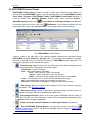
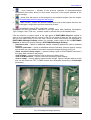
1
PHOTOMOD 4.4 Overview USER MANUAL Racurs, Moscow, 2009 PHOTOMOD 4.4 1. PHOTOMOD system and RACURS Company ................................................................................ 4 2. Distribution kit ................................................................................................................................... 5 3. Personal computer requirements .................................................................................................... 5 3.1 Operating systems ........................................................................................................................ 5 4. Installation, starting and deinstallation .......................................................................................... 6 5. Protection........................................................................................................................................... 8 6. Resources and networking .............................................................................................................. 9 7. PHOTOMOD network version......................................................................................................... 10 7.1 General info................................................................................................................................. 11 7.2 Resources storage in PHOTOMOD system ............................................................................... 12 7.2.1 Recommendations for the storages creation....................................................................... 12 7.2.2 Storages creating................................................................................................................. 13 7.2.3 Resources access setup ..................................................................................................... 14 7.2.4 Filling storages while working with a project ....................................................................... 15 8. PHOTOMOD local version .............................................................................................................. 15 9. PHOTOMOD System Monitor module ........................................................................................... 16 10. PHOTOMOD Control Panel........................................................................................................... 17 11. PHOTOMOD Explorer.................................................................................................................... 19 12. Geodetic calculator ....................................................................................................................... 23 13. PHOTOMOD MSTiff Maker utility ................................................................................................. 26 14. PHOTOMOD RasterView utility .................................................................................................... 28 14.1 Image printing ........................................................................................................................... 29 14.1.1 Printing settings ................................................................................................................. 30 15. Service tools .................................................................................................................................. 31 15.1 “Miscellaneous Utilities” program.............................................................................................. 31 15.1.1 Search & Replace in DGN files ......................................................................................... 31 15.1.2 Merge DGN files ................................................................................................................ 32 15.1.3 Fill sheets by polygons ...................................................................................................... 32 15.1.4 Replace font size in MIF/MID files ..................................................................................... 33 16. Equipment for stereo measurements.......................................................................................... 34 16.1 Stereoglasses ........................................................................................................................... 34 16.2 Video cards ............................................................................................................................... 36 16.2.1 Driver setup ....................................................................................................................... 38 16.3 Monitors .................................................................................................................................... 40 16.3.1 Stereo monitors ................................................................................................................. 41 16.4 Mice and hand wheels adjustment for stereo processing......................................................... 43 16.4.1 Three and five button mice ................................................................................................ 46 16.4.2 Immersion SoftMouse........................................................................................................ 47 16.4.3 GeoMouse ......................................................................................................................... 48 16.4.4 Stealth 3D Mice ................................................................................................................. 50 16.4.4.1 Stealth 3D Mouse-U ................................................................................................... 50 U © 2009 2 Overview July 25, 2009 16.4.4.2 Stealth 3D Mouse-Z ................................................................................................... 52 16.4.5 Hand wheels and foot pedals ............................................................................................ 55 16.4.5.1 Immersion compatible hand wheels and foot pedals ................................................. 55 16.4.5.2 Hand wheels and foot pedals “Vector-A” ................................................................... 56 16.4.6 Macro editor....................................................................................................................... 58 16.5 Hardware settings for working in stereomode .......................................................................... 62 17. Distributed processing ................................................................................................................. 64 17.1 General information .................................................................................................................. 64 17.2 Initial setup ................................................................................................................................ 65 17.3 Monitoring distributed processing ............................................................................................. 66 17.3.1 Tasks in queue .................................................................................................................. 66 17.3.2 Computers ......................................................................................................................... 67 17.3.3 Finished tasks.................................................................................................................... 68 18. Acknowledgments......................................................................................................................... 70 19. Glossary ......................................................................................................................................... 71 3 RACURS Co., Ul. Yaroslavskaya, 13-A, office 15, 129366, Moscow, Russia PHOTOMOD 4.4 1. PHOTOMOD system and RACURS Company PHOTOMOD is a digital system providing full photogrammetric production line from the aerial triangulation to output digital terrain models, digital maps and orthomosaics. PHOTOMOD system contains tools for processing aerial photos and scanner satellite images from different sensors such IKONOS, QuickBird, SPOT, IRS, ASTER, FORMOSAT, CARTOSAT, etc. Due to the system modular structure the user can choose the necessary configuration when purchasing the software. Network system version opens wide opportunities of working with a project simultaneously from several workplaces. PHOTOMOD system is produced by Racurs Co. (Moscow, Russia) and has been dynamically developing since version 1.1 in 1994. PHOTOMOD's growing user base includes organizations throughout more than 45 countries worldwide. The main fields of application include photogrammetric production, cadastral mapping, cartography and remote sensing, academic photogrammetry, mining, architecture and construction. You can get the additional information about Racurs and PHOTOMOD from: − Racurs web-site: www.racurs.ru − E-mail: [email protected] − Phone: (+7-495) 720-5127 − Fax: (+7-495) 720-5128 − Mail: RACURS Co., Ul. Yaroslavskaya, 13-A, office 15, Moscow, Russia Fig.1 Digital Photogrammetric Workstation PHOTOMOD © 2009 4 Overview July 25, 2009 2. Distribution kit Fig.2 Distribution kit The PHOTOMOD system distribution kit includes: - CD-ROM containing the system setup files and the documentation files in PDF format - hard lock key 3. Personal computer requirements The recommended PHOTOMOD workstation configuration may be as follows: • CPU: Pentium 4; 3.0 GHz, or similar • RAM: 1-2 Gb • For effective networking: network card 1000 Mb/s • HDD: you should keep in mind that working with big enough projects requires a considerable amount of the disk space. For example, the standard aerial image – 23 by 23 cm scanned with 20-mkm resolution (1200 dpi) is about 400 MB in uncompressed mode in PHOTOMOD image format (TIFF with a pyramid). If you use jpeg compression with a “quality” 80 percent, the image file size is about 80 MB. • Graphic card: see the chapter 15 Equipment for stereo measurements. 3.1 Operating systems PHOTOMOD system works under MS Windows 2000 and MS Windows XP operating systems. You are recommended to use MS Windows XP operating system (with installed Service Pack 2). Note. MS Windows Vista operating system does not support page-flipping stereomode at the moment. That is why work in PHOTOMOD in this system in page-flipping stereo mode (vectorization, tie points measurements, etc.) is impossible 5 RACURS Co., Ul. Yaroslavskaya, 13-A, office 15, 129366, Moscow, Russia PHOTOMOD 4.4 4. Installation, starting and deinstallation PHOTOMOD system installation requires 200 Mb free space on hard drive disk (for program files). Disk space required for data placement and storage is described below in appropriate chapters. During installation you should also consider the following: • PHOTOMOD system should be installed under administrative account. For further work standard user rights are enough; • in case of network PHOTOMOD version you should also install or update license manager HASP HL (Imsetup.exe file from Lmanager folder in PHOTOMOD distribution kit). The license manager must be installed on the PC the hard lock key is attached to. Then create or edit configuration file NetHasp.ini, which is located in Windows folder of each working station. The file should contain name of computer, where hard lock key HASP is attached. Standard NetHasp.ini file is created automatically during system installation, its further adjustment is performed manually, if needed. See also the chapter 7.1 General info. • hard lock key drivers are installed automatically along with local version of PHOTOMOD system. It may require reboot of operating system prior to the first PHOTOMOD start. In case of any errors corresponding with the system protection, try to install key drivers “manually” by running of HASPUsersetup.exe from HASP folder in PHOTOMOD distribution kit. Launch setup.exe file from PHOTOMOD distribution kit to start PHOTOMOD system installation. All necessary system settings are performed directly during installation. After its completion PHOTOMOD system is ready to work entirely. Installation process consists of several steps; each of them is accompanied by instructions in Installation help window (Fig.3). In case of some interruption of any step, program and data files already installed are not deleted, however you have to re-start installation after that and pass all steps once more. © 2009 6 Overview July 25, 2009 Fig.3 PHOTOMOD system installation and setup Installation process consists of the following steps: Preparation stage • Step 1: just push the Next button. • Step 2: read End user license agreement. If you agree mark the appropriate check box and push the Next button. • Step 3: select the folder on your PC to install PHOTOMOD system modules (usually C:\Program Files). • Step 4: select system components for installation considering free space on the disk chosen. • Step 5: enter the shortcut folder name to be shown in Start menu. Files copying • Step 6: push the Next button, to start installation of PHOTOMOD system on your PC. • Step 7: after files copying push the Next button and go to initial system configuration. System configuration stage • Step 8: it is necessary to check off this option, to launch PHOTOMOD System Monitor application while starting Windows. See also the chapter 7 PHOTOMOD network version. • Step 9: on this step select a folder for storing some PHOTOMOD system service information – the default one is PHOTOMOD.VAR folder in root directory of the system disk with recommended size not less than 1 Gb (do not mismatch with special folders for the data storing – storages – see the chapter 6 Resources and networking). You are not recommended to place this folder on network disk, because it would speed down the work of system significantly. 7 RACURS Co., Ul. Yaroslavskaya, 13-A, office 15, 129366, Moscow, Russia PHOTOMOD 4.4 After that you should also input the unique ID of work station in PHOTOMOD system, which is used for synchronization in cooperative access to working resources from several computers. It may be equal to the computer name in the Windows network, except that PHOTOMOD machine name must contain only letters of the Latin alphabet, digits and underline symbol. Computer name must be unique between the computers accessing the same data (resources). Note. Once-set machine name could be changed only during next PHOTOMOD installation • • • • Step 10: storages creating and/or connecting – most important step in PHOTOMOD system setup (see Fig.3). See chapters 10 PHOTOMOD Control Panel and 7.2 Resources storage in PHOTOMOD system. Step 11: if storages connected during previous step do not include necessary coordinate systems databases, select and install one or several coordinate system databases provided by PHOTOMOD installer. You can add coordinate system databases later using the corresponding option of PHOTOMOD Montage Desktop module or Control panel. Refer to PHOTOMOD Montage Desktop User Manual for detailed description of PHOTOMOD coordinate systems and map projections. Click the Next button after database installation. Step 12 (only for network version): indicate computer name in local network, where HASP hard lock key is connected to. See also the chapter 7.1 General info. Step 13: turn on options suggested if necessary and start main system modules, then push the Finish button to exit from installation process. Note. Prior to start PHOTOMOD make sure that PHOTOMOD System Monitor module (shown by the icon in Windows system tray, see the chapter 9 PHOTOMOD System Monitor module) is launched. If it is not, you should start it using the command START | Programs | PHOTOMOD | Utility | PHOTOMOD System Monitor Afterwards you can change this initial configuration using PHOTOMOD Control Panel or PHOTOMOD Explorer (see the chapters 10 PHOTOMOD Control Panel and 12 PHOTOMOD Explorer). Main system module PHOTOMOD Montage Desktop is launched using shortcut, created on (if the appropriate option was marked during installation), or using Windows Desktop double click on System Monitor icon shown in Windows system tray or using other ways described in PHOTOMOD Montage Desktop User Manual. To uninstall PHOTOMOD system from your computer use the command Start | Programs | PHOTOMOD | Uninstall PHOTOMOD or the standard remove programs procedure from OS Windows Control Panel. At that all running PHOTOMOD modules should be closed. 5. Protection The PHOTOMOD system is protected by HASP hard lock key from Aladdin Co. The hard lock key drivers are installed automatically along with the local version of PHOTOMOD system. In case of any errors corresponding with the system protection try to install key drivers “manually” by running of HASPUsersetup.exe from HASP folder on your installation CD. © 2009 8 Overview July 25, 2009 In case of network PHOTOMOD version the driver is not installed on work stations, however you should install license manager (Imsetup.exe file from Lmanager folder). The license manager must be installed on the PC the hard lock key is attached to. Please note that work in PHOTOMOD network version impacts considerably on resources of the computer where network hard lock key and License manager have been installed. That is why hard lock keys producer (Aladdin company, www.aladdin.ru) recommends to install the key on the isolated machine, where (CD/DVD recording, for instance) are not launched. You should keep in mind that HASP HL licence manager impacts considerably on computer resources. That is why resource-intensive tasks (CD/DVD recording, work in PHOTOMOD, etc.) on computer with network hard lock key installed may lead to failure of protection system, followed by disturbances in work with PHOTOMOD system on working stations up to data loss. It is recommended to install network hard lock on isolated machine, where resource-intensive tasks are not launched. 6. Resources and networking One of the PHOTOMOD software's distinctive features is the special system of project data storage and handling oriented on distributed network data processing. No matter in what folders and on what PCs in the LAN data are stored, an operator working in any of PHOTOMOD modules sees these data as a single virtual folder containing all accessible PHOTOMOD projects. Files stored in this virtual folder are called resources, while this virtual folder as a whole is called PHOTOMOD resources system. Physically files are stored in folders of the ordinary file system. These folders are called storages. PHOTOMOD resources system is administered completely by PHOTOMOD tools. No manipulations with resources from outside the system are implemented. During the PHOTOMOD installation procedure folders are indicated which will be used as storages and all further data distribution within the resources system will be done automatically. To control the accessibility of storages and availability of free space in them PHOTOMOD System Monitor is used. PHOTOMOD System Monitor provides permanent control of local and remote storages and generates warnings in case some of remote storages become unaccessible. Apart from working with resources in a completely automatic way, the user can manually set up data distribution options. Advantages of the implemented system of resources are as follows: • Possibility to distribute data of one project to different disks and network folders. This feature is very useful in working with large projects. • Fully automated data distribution. All free space in all connected storages is available for any newly created project. • Easy configuration procedure. Storages structure is configured only once in the process of system installation (or later using PHOTOMOD Control Panel utility). All further data distribution is implemented without user intervention. • Better structured data storage. All existing projects are located in a limited number of folders not spreading out over the disk space. As soon as a storage is connected to the system, all projects stored in it become available. • Flexibility. System tools for managing data distribution allow if necessary to move any resources from one storage to another and to define the data distribution rules. • Efficient use of available disk space. Automatic distribution of resources among storages is made in such a way that free space in them decreases evenly. Until the total volume of data is essentially less than available disk space you would not face the problem of absence of free space in any of storages. 9 RACURS Co., Ul. Yaroslavskaya, 13-A, office 15, 129366, Moscow, Russia PHOTOMOD 4.4 • • Convenient way of data sharing. No matter on what computer in the network a particular resource is located, this resource appears in "Load/Save" dialogues immediately. There is no need to select different folders as when working with ordinary files. Fast access to network resources. If it complies with company security rules PHOTOMOD can be configured to automatic network password enter when accessing storages located on remote computers. PHOTOMOD Explorer which is used for resources management has the user interface similar to Windows Explorer interface. This module provides the possibility to view and edit most of PHOTOMOD resources as well as many other useful service functions. See the chapter 11 PHOTOMOD Explorer. Montage Desktop module allows to backup projects in the form of ordinary folders and files and also to restore projects from backup copies to the system of PHOTOMOD resources. Backupped projects can be restored with network configurations different from that was used when backup was created. Restored projects are ready to use without any further adjustment. PHOTOMOD Control Panel utility allows to control the access to storages and free space in them. It is also possible to connect/disconnect storages. See the chapter 10 PHOTOMOD Control Panel. Rich experience of Racurs company production department gives rise to the following recommendations concerning storages configurations and data distribution: • For local configurations (when there is only one PHOTOMOD workplace or only one operator works with each project and data exchange between workstations is not considerable) it is recommended to create local storages at each workstation to benefit from higher local disk access speed versus access speed through the local network. • For network configurations when project data are processed simultaneously by many operators from different workstations it is recommended to have a special server which is not used as a workstation and place the storage (storages) on it. It is not recommended to store shared data on a computer used as a workstation because of increased danger of computer failure and hence failure in data access. This does not increase essentially the probability of data loss but decreases the overall productivity. When preparing a computer for working as a file-server please pay special attention to selection and configuring of operating system. Microsoft Windows 2000 Server or FreeBSD is recommended. Both these systems showed best results in testing as servers in the photogrammetric production line. If you are going to store data on a computer with nonserver version of Windows (NT, 2000 or XP), please take into account that such operating systems have a restriction on the number of network connections and if more than 10 computers are in the LAN, simultaneous work will be difficult or impossible. PHOTOMOD system has a lot of other service functions to facilitate working with large volume of photogrammetric data. 7. PHOTOMOD network version Recommended network configuration is as follows. PHOTOMOD storages with projects data are located on several file-servers (depending on work volumes of particular workflow). Generally, one storage should be located on one physical drive. It is preferable (however not always realizable in reality) to arrange data placement in a way, when PHOTOMOD project or project group with common images is located in several storages (according to volume occupied), located on different servers. It allows to provide more uniform load distribution on servers and network, when performing divided job processing of one project from several © 2009 10 Overview July 25, 2009 working stations. At that you are recommended to place each project in not more then three storages. Working stations (operator's work places) should be connected to servers using gigabit interface. Server operating system, for instance, FreeBSD, Windows Server or Linux should be installed on file-server. You should keep in mind, that non-server versions of MS Windows have limitation on 10 simultaneous network connections. Computing capacity of file server does not matter, commonly it is Intel or Asus motherboard, Celeron 2.0 GHz processor, RAM 512 Mb or 1 Gb. The most important is reliability of data storing. Since the License manager is resourceintensive, you should not connect a hard lock key to working station, it should be connected to one of the file-servers with storages or to separate machine. See also the chapter 6 Resources and networking. 7.1 General info Data access in PHOTOMOD system is realized only by means of operating system (through network access to files and folders). That is why you have to meet the following requirements: 1. All PHOTOMOD users should possess administrative credentials in OS Windows for PHOTOMOD storages access. 2. Groups of storages connected to different working stations should be the same or should not intersect. For instance, if the network includes A, B and C storages, and A and B storages are connected to one working station, then other stations should be connected just to A and B storages, or just to C storage. If you connect B and C storages without A storage to some other working station, it may result in errors. 3. All storages connected to working station should be available during working in PHOTOMOD system on this computer. 4. All changes in storages list executed in the Control Panel or manually become available for launched PHOTOMOD modules only after their re-launching. 5. If PHOTOMOD system storages are located on server, you should keep in mind the total amount of simultaneous accessing users to it. Some operating systems have limitations for such access. In non-server operating systems (Windows 2000/XP, for instance) there are limitations on such simultaneous access so it is recommended to have at most 7 operators working with server storages at the same time in non-server OS. It is recommended to use the following server operating systems: FreeBSD, Linux or likewise, or MS Windows Server. 6. During installation of network version of PHOTOMOD system on working station to Windows system folder (usually C:\Windows) NetHasp.ini file is installed either. The file contains computer name where HASP hard lock key has been installed. If hard lock key is after some time installed to another computer, you should edit corresponding string in ini file and input new computer name as IP address or network name (Fig.4). After that you should restart PHOTOMOD system for the changes to take place. 11 RACURS Co., Ul. Yaroslavskaya, 13-A, office 15, 129366, Moscow, Russia PHOTOMOD 4.4 Fig.4 Nethasp.ini file example The example of Nethasp.ini file is shown on Fig.4 and computer name is indicated by the red line. 7.2 Resources storage in PHOTOMOD system 7.2.1 Recommendations for the storages creation The system flexibility allows you to manage storages and computers in PHOTOMOD network as you need. Nevertheless there are some recommendations to speed up time consuming operations such as 3D feature extraction and TIN editing: • In case of work with project on local machine (each project is processed on separate computer), storage is created locally on each machine. • In case of working with a project located on the file-server: - open file-server hard drives for reading-writing operations on computers of PHOTOMOD network (by standard tools of OS Windows) - create a storage of needed size on the file-server During the further work you can control the access to the storages in PHOTOMOD Control Panel program (Path column). © 2009 12 Overview July 25, 2009 General case of working with the network project. PHOTOMOD project resources are located on several network workstations. At that any number of storages may be created on different computers. The general rule of storages creation is creating local storages on the computers opened for reading-writing in LAN. Note that the storages on the local hard drives will be “filled” with data first, during project creation and processing. Once the storages on the local disks are full, the network storages will be filled. You should not create several storages locally, since all of them use the same disk space. When several operators are working with a project on different computers simultaneously you are recommended to consider the following: • do not start PHOTOMOD AT and PHOTOMOD Solver modules at the same time on different computers • do not open the same resources with TINs, vector objects, contour lines, etc. simultaneously on different computers. 7.2.2 Storages creating Click the icon Add storage in main menu of the Control panel, which opens Create/connect storage window (Fig.5). Select a path to the storage folder (Folder name field) in the local/remote computer file system. Enter the storage identifier (ID field). The ID is a case-sensitive string of Latin characters, digits and underline symbol. Then specify the disk space reserve for the storage (Disk space reserve field). Push the Connect button to create the storage. As a result the storage is added to the list in PHOTOMOD Control Panel window. See the chapter 10 PHOTOMOD Control Panel. Fig.5 Resource storage creation If access to remote storage is denied for the user, who was logged on local PC, it is recommended to use automatic user authorization on remote PC by checking off Automatic authorization option and entering user name who is allowed to access remote storage and its password. At that the user should be registered on the machine where the storage is located, and also indicated in network access settings in the storage folder. The password will be saved as a plain text in Storages.ini file in subdirectory Config in system settings directory. If you are trying to connect to PHOTOMOD system the storage locating on the same local or remote disk where there is already connected storage, you will get warning message (see also the chapter 7.2.1 Recommendations for the storages creation). In case when connecting storage is in previous PHOTOMOD version format, you will be suggested to transform storage format. At that storage directory format will be changed (file 13 RACURS Co., Ul. Yaroslavskaya, 13-A, office 15, 129366, Moscow, Russia PHOTOMOD 4.4 $PhStorage.dir, its initial version will be saved in file $PhStorage.dir.old), and files of these resources will be moved to Content subdirectory. Note. After storage connecting/disconnecting, restart all opened PHOTOMOD modules to activate all changes in storages system In case of some storage fail you should create the report about current state of PHOTOMOD storages connected to the computer and send it (file with .tar extension) to the technical support service. For that you should use the command Start | Programs | PHOTOMOD | Utilities | Storage state report or run the utility from PHOTOMOD Control Panel by menu command Storages | Repair tools | Create report (see the chapter 10 PHOTOMOD Control Panel). Note. Prior to send you should compress the report using any archiver to reduce its volume 7.2.3 Resources access setup In order to increase the reliability of PHOTOMOD system working in the LANs of different configurations, you can adjust some setting parameters in case of some problems with resources accessibility. Use menu command Service | Setup resource access system in PHOTOMOD Control Panel to set up these parameters (Fig.6). Fig.6 Resources access parameters Parameters description: • Storage access timeout – when several LAN-computers are trying to access the storage simultaneously, the storage table is blocked by one of them. Given parameter allows to setup “waiting” time for access the storage table, currently occupied by the other computer (or application), before warning message appearing. It is recommended to increase the parameter if you are working in quite big LAN and receiving the messages like “Impossible to open the resource”. Especially needed while several users are working in PHOTOMOD AT module simultaneously because in this case saving operations are taking place more frequently than in other modules. © 2009 14 Overview July 25, 2009 • Maximum backup size – shows the volume of previous cache table copies, saved on disk. If total volume of previous files copies exceeds this parameter, the oldest files will be deleted, in order to keep their volume less than given. • Maximum storage table delta cache size – to speed up storage table saving, there is the table cache containing the last changing in storage. When the cache reaches determined size this changing (delta cache) is saving to the main table. • Save storage table cache every – this parameter determines storage table cache “age limit”, after reaching it cache will be added to the main table. • Automatically restore storage table after failure – in case of storage failure the system will try to restore it automatically (if the option is ON) or you can do it yourself using the option Restore storage table in PHOTOMOD Control Panel (see the chapter 10 PHOTOMOD Control Panel). 7.2.4 Filling storages while working with a project Current free space in the storage can be calculated as a difference between the free space on the corresponding hard drive and the Disk space reserve value selected during the storage creation (see the chapter 8.2 Resources storage in PHOTOMOD system). If there is storage available on the local computer, it is filled in first while working with a project that allows to speed up file access. In most cases the system controls the needed disk space when creating big enough resources and “put” them into the appropriate storages. Besides there are some tools of monitoring storages free space in PHOTOMOD Control Panel (Free space column) and PHOTOMOD Explorer programs (see the chapter 11 PHOTOMOD Explorer). The icon (storage space control) located in PHOTOMOD Explorer or in upper icon menu of PHOTOMOD Montage Desktop module opens a window showing free space on the project host computer (Fig.7). Fig.7 Storage space control When starting disk space consuming process (like adding images to the project) the system displays warnings if the disk space is not enough. In order to increase the space you can create new storages (see the chapter 7.2.2 Storages creating). 8. PHOTOMOD local version Network PHOTOMOD configuration is preferable in very most cases – it allows to organize work of operators more flexible and use production facilities more comprehensively. Nevertheless there is also a local system version. Moreover, when working in local version you should install the set of all required modules and local hard lock key on the each working station. It would be advantageous for moderate projects processing on 1-2 local machines. And if you are going to have photogrammetric works of big enough volume it is more reasonable to use network version. 15 RACURS Co., Ul. Yaroslavskaya, 13-A, office 15, 129366, Moscow, Russia PHOTOMOD 4.4 9. PHOTOMOD System Monitor module After PHOTOMOD system installation PHOTOMOD System Monitor (PhMonitor.exe) . If the module is launched. It is visualized in OS Windows System tray as an icon module was not launched for some reason, you should start it from Windows Start menu: Start | Programs | PHOTOMOD | Utility | PHOTOMOD System Monitor. Fig.8 Pop-up menu of PHOTOMOD System Monitor When PHOTOMOD system is ready to work, the icon in System tray turns from sandglass into grey ball. Besides, if some PHOTOMOD storage is unavailable yellow triangle with exclamation mark is added to the icon. Context menu of PHOTOMOD System Monitor module is opened after right click on the “ball” and contains the following commands: PHOTOMOD Montage Desktop – starts the main PHOTOMOD system module – PHOTOMOD Montage Desktop (also is launched using double click on the afterwards starts the work in PHOTOMOD system icon) and Control Panel – to start an appropriate application (see the chapter 10 PHOTOMOD Control Panel) PHOTOMOD Explorer – to start an appropriate application (see the chapter 11 PHOTOMOD Explorer) Distribution info – opens a window with information on PHOTOMOD modules configuration and hard lock key ID. You can save the information to text file and send it to tech. support service Mouse configuration – allows to setup a configuration of mice or other special devices (like hand wheels/foot pedals), which are used for images stereo processing (see the chapter 15.4 Mice and hand wheels adjustment for stereo processing) Enable sound – allows to turn on/off the sound which accompanies opening or closing of PHOTOMOD System Monitor module About – opens a window indicating the number of system build and serial number of hard lock key Exit – closes PHOTOMOD System Monitor module and exits from PHOTOMOD system. © 2009 16 Overview July 25, 2009 10. PHOTOMOD Control Panel PHOTOMOD Control Panel program is used to setup and control the local network for working with the PHOTOMOD system. Use the following way to start PHOTOMOD Control Panel: Start | Programs | PHOTOMOD | Utility | PHOTOMOD Control Panel. Besides, it could be started from Montage Desktop module using menu command Project | Open/Management and the icon Control Panel (see Montage Desktop User Manual), or also use right mouse click on the icon (PhMonitor) in OS Windows System tray, and select then pop-up menu item Control Panel. The program window looks as follows: Fig.9 PHOTOMOD Control Panel There is a table in the main part of the opened window containing the information about PHOTOMOD storages (Resource storages tab). The storages are displayed as folders selected on different PCs in the network for storing of PHOTOMOD system resources. The icons at the upper part of the window are used to: • - Reload storage state. Click the icon to refresh the current state of storages and to show the following data in appropriate columns the table: - identificator – name of storage; - state – status and location of storage: - local – local computer “owns” the storage - remote – remote computer “owns” the storage - offline – no access to the storage and the cache is not available - owner – the identifier of PC in local network that hosts the storage; - path – the storage folder name with a network or local path; - free space – free space in kilobytes on computer-owner of the storage • - Add storage. Allows to create or add storage on the local or remote computer. See the chapter 7.2.2 Storages creating • - Disconnect storage. Allows to disconnect selected storage. All data remain on the disk and the storage may be connected back (added) later • - Edit configuration files. Opens a list of the system initialization files for editing in text editor. The user can edit .ini files only in case of the corresponding requirements from the Racurs technical support department • - Install coordinate systems database (See Montage Desktop User Manual) • - Start PHOTOMOD System Monitor. Launches the module, and the icon appears in right lower corner of OS Windows Desktop. See the chapter 9 PHOTOMOD System Monitor module 17 RACURS Co., Ul. Yaroslavskaya, 13-A, office 15, 129366, Moscow, Russia PHOTOMOD 4.4 • - Start PHOTOMOD Explorer. Launches program intended for work with PHOTOMOD system resources. See the chapter 11 PHOTOMOD Explorer • - Start Montage Desktop. Launches the main PHOTOMOD module. See also the chapter 6 Resources and networking. Upper menu of Control panel window contains the following commands: ♦ Storages – allows to work with PHOTOMOD storages o Reload storage state – duplicated by the icon o Add storage – duplicated by the icon o o Disconnect storage – duplicated by the icon Repair tools – in case of malfunction in storage work, it is recommended to select the following options from pop-down menu: Create report – to save current storage state (at that storage record should be selected in the table) into archive file *.tar to the user defined path for further sending it to technical support group. This file contains current storages and PHOTOMOD system configuration. You can add other information to this report using options of the following window: Fig.10 PHOTOMOD settings report creation ♦ Restore storage table – automatically restores the storage selected Service – contains the following commands: o o o © 2009 Edit configuration files – duplicated by the icon Setup resource access system – see the chapter 7.2.3 Resources access setup Configuration manager – opens a dialogue for creating and/or changing of storages set currently connected to your PC: 18 Overview July 25, 2009 Fig.11 Selecting storages configuration This window is used to select existing storages set (configuration) and assign it to the project being created, or to arrange new configuration supposed to be used for storing of all project resources. Push the button Create and input the name of storages configuration to create new configuration. o Install coordinate systems database – duplicated by the icon o Start PHOTOMOD Monitor – duplicated by the icon o Start Montage Desktop – duplicated by the icon o Start PHOTOMOD Explorer – duplicated by the icon Help (F1) – allows to open PHOTOMOD Overview User Manual and also informational panel on system version and hard lock key serial number (the About command) ♦ Exit – closes Control Panel window. ♦ 11. PHOTOMOD Explorer PHOTOMOD Explorer is a stand-alone program for working with PHOTOMOD system resources. You can use the following ways to start PHOTOMOD Explorer: • from OS Windows START menu: Programs | PHOTOMOD | Utility | PHOTOMOD Explorer. • • from pop-up menu which appears after right mouse click on the icon PhMonitor in OS Windows Desktop system tray. from PHOTOMOD Control Panel – see the chapter 10 PHOTOMOD Control Panel. After you get opened the window containing PHOTOMOD system resources tree. 19 RACURS Co., Ul. Yaroslavskaya, 13-A, office 15, 129366, Moscow, Russia PHOTOMOD 4.4 Fig.12 The list of projects in PHOTOMOD Explorer window The system resources include all PHOTOMOD-related files – projects, camera database tables, images etc. The resources are organized hierarchically – thus project resource refers to project images, TINs, vector objects, contour lines, etc. See also the chapter 6 Resources and networking. In the upper panel of PHOTOMOD Explorer window there are icons used for the following operations: • - copy resource to clipboard • - paste resource from clipboard (for example to another project) • - rename resource • - delete resource – allows to delete a resource or resource group selected in the right panel of the window. A resource folder selected in the left panel cannot be deleted. • - export resource to file (for example to pass it to the another computer out of PHOTOMOD network) • - import resource from file • (duplicated by F5 key) - refresh/view modes – allows to select the type of resources or projects list from pop-down menu. If resources or projects are shown as a table, you can sort their properties (Description, Type, Subtype, Size, Time, etc.) indicated on the right panel using mouse click on column header • - folder size – in case of selected folder (project or its resource) opens an additional panel showing the number of resources in the folder and its volume in Kb • - resource properties – in case of selected resource in the left part and the resource in the right part opens a window with a list of its properties used to view them or edit some of them (the resource description for example) © 2009 20 Overview July 25, 2009 Fig.13 TIN resource properties • • - shows resources in all subfolders relatively to the one selected in the left list - projects placement – opens an additional window containing in its left column projects list and placement of their resources in PHOTOMOD storages connected to your PC in current PHOTOMOD session. Fig.14 Projects placement in storages In this window you can change the storage where the project or/and its images are stored. For this proceed as shown on Fig.14: in Projects placement window select the project located in remote storage PhStorage2 (see an appropriate column), and push the button Move project/rasters. In appeared window Resources placement select the same storage PhStorage2, push the button Move selected and in new additional window Move resources, select the storage where you like to move your project, then push the Move button. As a result the project and all its resources are moved into storage specified. At that you should keep in mind that project volume should not exceed the volume of free space in the target storage. 21 RACURS Co., Ul. Yaroslavskaya, 13-A, office 15, 129366, Moscow, Russia PHOTOMOD 4.4 • - move resources – similarly to the previous operation of resources/projects replacement this button allows to move some resources of the project selected to the chosen storage • - shows free disk space in the storages for the selected project (see the chapter 7.2.4 Filling storages while working with the project) • - raster control – opens new window containing the list of the projects stored in the current storages configuration and their rasters list as well. • (duplicated by hot key F1) - help index – opens Resources and their properties, indicated in the right panel table headings (Description, Type, Subtype, Size, Time etc.), could be sorted by mouse click on the header button. Click the resource or project name in the right panel of PHOTOMOD Explorer window to open a list of operations with the resource (see Fig.14). Most of them are the service ones and are not really useful for the end user. Some of these listed below are duplicated in PHOTOMOD Montage Desktop module (for example, export project to file in PHOTOMOD Explorer is identical to project backup in PHOTOMOD Montage Desktop). - placement rules – opens an additional window containing placement rules for selected resource - resource placement – opens an additional window indicating resource and its storage and whether you can replace it to another connected storage as shown on Fig.14. - delete resource backup copies – deletes backup copies of PHOTOMOD resources if they have been created in the project - view in binary – opens window to view a resource in binary form - view as DTM resource – used for resources containing vector objects - view as image – used to display resources with images. Opens a window with an image that can be saved into TIFF or BMP formats and resampled (according to SubSample parameter) Fig.15 Viewing the image resource © 2009 22 Overview - - - July 25, 2009 view as INI-file view as text copy – copies resource to clipboard paste – pastes resource from clipboard (for example to another project) rename – renames resource delete – deletes resource export – exports resource to file import – imports resource from file show hidden resources – shows/hides hidden resources in PHOTOMOD Explorer window, for example files of PHOTOMOD resources backup and to restore them if needed show additional details – turns on an additional columns with information, that also could be sorted by mouse click on the column header: ∗ ID – resource identifier in PHOTOMOD system ∗ Host – local computer, the host of the current resource ∗ Storage – name of the storage where the resource located properties (duplicated by the icon ) – opens a window with the resource properties (ID, type, subtype) for viewing and editing (such as the description), see Fig.13. 12. Geodetic calculator An additional PHOTOMOD system utility, used for recalculating of ground control points coordinates from one coordinate system into another. Prior to work with GeoCalculator you should install coordinate systems database during PHOTOMOD system installation (see PHOTOMOD Montage Desktop User Manual). Geodetic Calculator is starting from OS Windows Start menu: Start | Programs | PHOTOMOD | Geodetic calculator. At first program launch you should specify the path to folder containing coordinate systems database in the window appeared. Fig.16 Selection of folder with coordinate system database 23 RACURS Co., Ul. Yaroslavskaya, 13-A, office 15, 129366, Moscow, Russia PHOTOMOD 4.4 Then the dialogue of the program settings is opened, (also could be opened using menu Options). Upper panel of the window – command Tools | Options, or the icon Database directory – shows the path to the database folder and allows to change it if needed. If coordinates calculations have poor result the field with invalid value is shown in red color (by default) or by color selected in drop-down list in Colors panel. Fig.17 Program settings Interface mode panel allows to select one of two working modes: Standard and Advanced which have different set of menu commands (appeared after pushing Database menu option) for work with coordinate systems database. Standard set of Database menu contains the following items: Advanced set of Database menu contains the following items: After pushing the button OK in Options window the main PHOTOMOD GeoCalculator window is opened. © 2009 24 Overview July 25, 2009 Fig.18 Program window (Fig.18) consists of two panels – left and right. One of them is intended for initial GCP data input and the other – for displaying of recalculating results. For example, you have initial GCP coordinates set in geodetic coordinate system (Lat, Long, H). In order to re-calculate them into Cartesian, which are acceptable in PHOTOMOD system you should do the following. Push the Select button in Reference system field of the left panel and select coordinate system of input GCP’s. Then load ASCII file with points coordinates (the Load button in left Points field). In the right panel in Reference system field exactly in the same way select the output coordinate system (from Cartesian ones available, for example) and recalculate the coordinates (the Calculate button under left Points field or the icon Calculate from left to right). After that, new GCP coordinates appear in the right Points field. You can save them in txt file (the Save button under right Points field) and use then in further work with PHOTOMOD project. 25 RACURS Co., Ul. Yaroslavskaya, 13-A, office 15, 129366, Moscow, Russia PHOTOMOD 4.4 Fig.19 Operations of point’s coordinates selection and recalculation may be performed both from left to right panel (as described above) and vice versa – from right to left panel. In the latter case use the icon Calculate from right to left. Moreover, GeoCalculator program allows to view, select, edit and also export/import coordinate system databases, using commands of the Database menu item (Fig.19). 13. PHOTOMOD MSTiff Maker utility In some cases when you create the projects with big number of images located on different media and which occupy a huge disk space, it is convenient to transfer them into PHOTOMOD MSTiff format even prior to new project creation. This format allows to speed up the access to the initial raster image and also to save disk space. For such transfer use the utility, opened by the following command: Start | Programs | PHOTOMOD | Utilities | PHOTOMOD MSTiff Maker. © 2009 26 Overview July 25, 2009 Fig.20 MSTiff Maker window In Source images window select the folder with images (upper window) and Tiff files stored there (lower window). You can add/exclude images files from Processing list window using arrow buttons located between the windows. Click these buttons to collect the set of images from different folders/computers to convert them afterwards in PHOTOMOD MSTiff format. The Conversion settings panel allows to set up the following parameters of image conversion: • Target folder – pop-down list to select the folder for resulting images storing; • File names modification – to add name prefix (Add prefix field) or suffix (Add suffix) to images names group; • Compress % – to specify initial images compression level after the conversion, 80% – by default; • Decompress – to allow decompressing of compressed images while converting. If target folder already contains files with the same names, you can overwrite them by new ones turning on the Overwrite existing files option. The buttons Start, Pause, Cancel, Close are used for converting process management and Ready, Current and Total fields – to view the process state. 27 RACURS Co., Ul. Yaroslavskaya, 13-A, office 15, 129366, Moscow, Russia PHOTOMOD 4.4 14. PHOTOMOD RasterView utility If you need to view initial raster images or convert them into formats, which are recognized by PHOTOMOD system, use PHOTOMOD RasterView utility, located in Utilities list (Start | Programs | PHOTOMOD | Utilities | PHOTOMOD RasterView). Click this command to open the following dialogue window. Fig.21 PHOTOMOD RasterView window First load the initial raster in Tiff or BMP format by pushing the button Open image. To visualize the image in the window mark the View check box. Lens window in right lower corner of the main window shows the part of the image located under marker rectangle. Output images are saved in the following formats: BMP, Tiff, MSTiff, MSTiff with LZW compression, MSTiff with JPEG compression. In the latter case you can set up compression percent of the initial image in Compression quality field. Besides, you can resample the output image pixels by setting the number of rejected pixels in Downscale factor field. For example, if downscale factor is 4, each raw and column of initial image is reduced by a factor of 4. After selecting format and conversion parameters push the Convert button to start the process. PHOTOMOD RasterView is also used for printing of an image opened in the program window, see the chapter 14.1 Image printing. © 2009 28 Overview July 25, 2009 14.1 Image printing PHOTOMOD RasterView is also used for printing of an image opened in the program window. Push the Print button to make settings of printing process in the window opened. Fig.22 Printing settings window - printer setup – open printer selection and setup window. Also activated by Ctrl-С shortcut. - parameters – open Printing settings dialog, see 14.1.1 Printing settings. - start print – starts printing image (or chosen sheets only) according to predefined settings - fit width – shows complete image fitting to width in print settings window - fit height – shows complete image fitting to height in print settings window - 1:1 – displays the image in the print window, in a scale of 1:1 (pixel image corresponds to the screen pixel) - zoom in – zoom in the image in the window 29 RACURS Co., Ul. Yaroslavskaya, 13-A, office 15, 129366, Moscow, Russia PHOTOMOD 4.4 - zoom out – zoom out the image in the window - drop-down list for choosing image scale (in %) - drop-down list for choosing color of printed sheet's borders - turn all pages off - turn all pages on - invert selection Individual pages can be included / excluded from printing by clicking on page image while pressing Ctrl button. Clicking the right mouse button on selected page makes a contextual menu appear with Print this page now command, which prints the page upon clicking. 14.1.1 Printing settings To set printing options for image, currently open in RasterView program, choose Print | Parameters menu item or click (Parameters) toolbar button, so that a window appears. Fig.23 Printing parameters Tiled pages tab can be used to customize division of the original image into pages. © 2009 30 Overview July 25, 2009 Printing order tab is intended to specify the printing order for image pages. Margins tab is used to adjust image indentations from page borders and bind printed image to paper corners. Fig.24 Selecting page margins 15. Service tools 15.1 “Miscellaneous Utilities” program PHOTOMOD includes a service program “Miscellaneous Utilities” for carrying out several group operations over vector and raster files. Shortcut for starting this program is located under the Utility group in the PHOTOMOD Start menu folder (Start | Programs | PHOTOMOD 4.4 | Utility | Miscellaneous Utilities). Upon starting the program, a window with the list of available operations is opened. 15.1.1 Search & Replace in DGN files 31 RACURS Co., Ul. Yaroslavskaya, 13-A, office 15, 129366, Moscow, Russia PHOTOMOD 4.4 This command is designated for searching and replacing text strings in a group of DGN v7 files. When the command is activated, the same-name dialog is shown. The dialog allows setting the following parameters: • Path to DGN files – folder to be searched for the DGN files to process (including all subfolders). • Text to find – text string to be searched for and replaced. • Replace with – text string to replace the Text to find. • Case sensitive – option controlling whether Text to find is matched against in case sensitive or insensitive way. When OK button is clicked, the given path is searched for DGN files, which in turn are searched for the text to find, which is replaced with replacement string. Files having unsupported format are not modified. Note: no backup copies of the processed files are created. 15.1.2 Merge DGN files This command is used to merge several DGN v7 files into single one. This may be necessary e.g. for creating summary files for several regions. When this button in the main window of the program is clicked, first an Open dialog is displayed for selecting input files to merge, then a Save as dialog is displayed to enter the name for the resulting merged file. 15.1.3 Fill sheets by polygons Sometimes during orthophoto creation there arises a requirement for the raster to be exactly limited by a set of polygons (describing e.g. settlement borders), all the rest being filled by the background solid color. In order to achieve this, the Fill sheets by polygons command may be used. When the corresponding button in the main window of the program is clicked, it brings up the same-name dialog. © 2009 32 Overview July 25, 2009 This dialog allows setting the following parameters: • Images files – image files to be processed. Acceptable formats include striped TIFF and BMP without compression, georeferenced. • File with polygons – vector files containing polygons to be used as borders. Acceptable are PHOTOMOD resources (.PHR), DXF, Shapefile (.SHP) formats. • Color – color to be used as the background fill. • Create backup – this option causes the program to create a backup copy (with .bak extension) before processing each raster file. • Swap X, Y – this option causes the X and Y coordinates of border polygons to be swapped before processing. Polygons must be specified in the same coordinate system as the raster georeference data. 15.1.4 Replace font size in MIF/MID files This command allows to adjust font size (by changing one specified value to another one) in a set of MIF/MID files. When the corresponding button in the main window of the program is clicked, an Open dialog is brought up to select the list of files to be processed, followed by the parameters dialog. The dialog allows setting the following parameters: • Output directory – defines the directory where the processed files should be save (the original file names are preserved). 33 RACURS Co., Ul. Yaroslavskaya, 13-A, office 15, 129366, Moscow, Russia PHOTOMOD 4.4 • • • • Input parameters group – sets width and height of a character in the input file to be searched for and replaced. The units correspond to the basic units in the file (e.g. meters). Output parameters group – sets width and height of a character in the output file (to substitute the size of characters matching input parameters). Number of "-" – defines the number of “-“ signs in the sheet names. Precision – number of signs after decimal separator to be used when writing coordinates. 16. Equipment for stereo measurements For 3D feature extraction and DTM and contour lines editing in PHOTOMOD StereoDraw, PHOTOMOD StereoVectOr and PHOTOMOD DTM modules three stereomodes are used – anaglyph, interlace or page-flipping. Stereo measurements require anaglyph (in anaglyph stereomode) and shutter glasses (in interlace or page-flipping stereomodes), see the details on stereomodes in PHOTOMOD StereoDraw and PHOTOMOD DTM User Manuals. Besides, for effective stereo processing some special equipment and its adjustment described below is needed. 16.1 Stereoglasses The following types of stereoglasses are tested for working with PHOTOMOD system. • Shutter glasses from IBIK, Co, Moscow, Russia (see also www.stereo-pixel.ru and www.ibik.ru for details). IBIK stereo glasses are connected to the computer using sockets of its controller in two places: one socket to com-port, and another one – between video adapter and monitor’s cable. You should also install the glasses driver from Glasses folder (setup_ sfv302.exe file) located on your installation CD-ROM. This folder contains also stctrl.chm file with additional useful information about glasses configuration. Fig.25 Connecting IBIK glasses You should adjust the driver after its installation. For that start the driver from the Preferences window of PHOTOMOD StereoDraw or DTM modules (menu command Service | Preferences | Stereo, © 2009 button) or from OS Windows 34 Overview July 25, 2009 menu Start | Programs | Stereo for Windows v.3.0 | Stereo for Windows. Then the is appeared in Windows desktop system tray. Right click on it opens pop-up icon menu where you should select Properties option that calls glasses driver setup dialogue: Fig.26 Adjustment of IBIK glasses driver Select Properties tab, push the button Autodetect there and after some time the system detects stereo mode settings automatically. Make sure they are as follows: • Glasses controller – Model – should be 3D Max-3 • Port should correspond to the PC COM-port where the glasses controller has been installed. • Video – Chipset should correspond to your video card chipset. • If you use page-flipping stereomode in Video – Mode field select Default option. Now the page-flipping stereo mode setup is over. Interlaced stereo mode requires different settings: Select Interlaced option in Video – Mode field. Video – Rate should be Default x 2. On Advanced tab check the Test the display before set a stereo mode option. After that push OK button and adjust your monitor frequency: choose maximal frequency, which does not allow the image to disappear after switching to stereo mode. Turn on stereo mode in driver’s menu, popped up after right mouse click on icon in system tray. After turning on of each stereo mode the driver will require confirmation. If you choose too big frequency and the image disappears when stereo mode is on. You should wait for 10 seconds and the initial mode of video card will be restored. When you get an appropriate frequency, un-mark the option Test the display before set a stereo mode on Advanced tab, after that the driver will not ask for confirmation at stereo mode start. • • 35 3DS-GM shutter glasses with 3DS-PC3 controller provided by STEL Corporation (Russia). Controller is connected between video card connector and monitor cable. Glasses are connected to operating unit of controller. The glasses do not require drivers' installation, it is enough to press the button OU/PF on operating unit. At that light diode should flash by green light. This type of glasses is used only for page-flipping stereo mode. NuVision shutter glasses provided by MacNaughton.Inc (see www.nuvision3d.com for details). There are two possible types of NuVision glasses: - NuVision 60GX – is used for video cards with special plug to connect the glasses. The glasses kit includes the IR-emitter and glasses. - NuVision 60GX-NSR – is used for video cards that do not have the glasses connection plug. The kit in this case consists of IR-emitter, glasses and the synchronization box. RACURS Co., Ul. Yaroslavskaya, 13-A, office 15, 129366, Moscow, Russia PHOTOMOD 4.4 Fig.27 NuVision 60GX-NSR glasses kit Beside the shutter glasses you can use simple anaglyph glasses with “red” and “blue” filters. Anaglyph stereomode requires no special equipment but it is not completely good for working with color images. Another disadvantage is that the picture gets a bit darker when viewing with filters. Fig.28 Anaglyph glasses 16.2 Video cards • For IBIK glasses work Video cards Matrox G200, G400, G450, G550 ATI Radeon Mach64, Rage, RageII, Rage128 Intel i740, i810, i815 Nvidia GeForce 2,3,4 Nvidia Quadro © 2009 Mode Interlace Pageflipping yes no yes yes Interlace mode configuration standard work using the IBIK driver standard work using the IBIK driver 36 Overview 3D labs Wildcat • yes yes Interlace mode is turned On by using the video card driver. Using IBIK driver in Default stereo mode turns On the glasses. For NuVision 60GX-NSR glasses work Video cards Matrox G200, G400, G450, G550 ATI Radeon Mach64 Rage, RageII, Rage128 Intel i740, i810, i815 Nvidia GeForce 2,3,4 Nvidia Quadro 3D labs Wildcat • July 25, 2009 Mode Interlace Pageflipping yes/no no no yes yes yes Interlace mode configuration Interlace mode is turned On using video driver on those video cards where it is possible. The button on the synchronization box turns On the glasses. Interlace mode is turned On by the video card driver. The button on the synchronization box turns On the glasses. For NuVision 60GX glasses work Video cards Nvidia Quadro4 380 XGL Quadro4 550 XGL Quadro4 580 XGL Quadro4 700 XGL Quadro4 750 XGL Quadro4 900 XGL Quadro4 980 XGL Quadro FX 330 Quadro FX 500 Quadro FX 1000 Quadro FX 2000 3D labs Wildcat VP760 Wildcat VP870 Wildcat VP970 Wildcat 4105 Wildcat 4110 Wildcat 4210 Wildcat II 5000 Wildcat II 5110 Wildcat III 6110 Wildcat III 6210 Wildcat 4 7110 Wildcat 4 7210 Interlace mode configuration Mode Interlace no Page-flipping yes yes yes Interlace mode is turned On by the video card driver. Glasses are On automatically PHOTOMOD system also supports ATI video cards (fireGL series) for work in page-flipping. Note. For working in page-flipping mode you need a video card supporting quadbuffering mode and its driver must support Open GL 1.2 and higher standard. For working in interlace mode the video card just should support interlace mode 37 RACURS Co., Ul. Yaroslavskaya, 13-A, office 15, 129366, Moscow, Russia PHOTOMOD 4.4 In case of using IBIK glasses you should install driver and set up the glasses in Default mode (see the chapter 15.1 Stereoglasses). If using NuVision 60GX glasses the IR-emitter is connected to the video card and the glasses are On automatically when switching to the stereomode. The NuVision 60GX-NSR glasses are turned On by pressing the button on the synchronization box. Note. When purchasing video card, make sure that its interface (AGP or PCI Express) is compatible with interface of the motherboard installed on your computer Below there is a list of some recommended video cards for work in page-flipping stereo mode. Nvidia Quadro2 Nvidia Quadro4 380 XGL Nvidia Quadro4 550 XGL Nvidia Quadro4 580 XGL Nvidia Quadro4 700 XGL Nvidia Quadro4 750 XGL Nvidia Quadro4 900 XGL Nvidia Quadro4 980 XGL Nvidia Quadro FX 330 (PCI Express interface) Nvidia Quadro FX 500 Nvidia Quadro FX 540 (PCI Express interface) Nvidia Quadro FX 1000 Nvidia Quadro FX 1300 (PCI Express interface) Nvidia Quadro FX 1500 (PCI Express interface) Nvidia Quadro FX 2000 3D labs Wildcat VP760 3D labs Wildcat VP870 3D labs Wildcat VP970 3D labs Wildcat 4105 3D labs Wildcat 4110 3D labs Wildcat 4210 3D labs Wildcat II 5000 3D labs Wildcat II 5110 3D labs Wildcat III 6110 3D labs Wildcat III 6210 3D labs Wildcat 4 7110 3D labs Wildcat 4 7210 Note. Graphic cards Nvidia of GeForce series do not support page-flipping stereo mode Actually the list of video cards in the table is not complete. However the out-of-list video card may need some adjustment and testing. 16.2.1 Driver setup PHOTOMOD system supports work in stereo mode with graphic cards both with stereo glasses connector (stereo-ready cards) and without it. In both cases you should make necessary settings of graphic card driver to work in stereo as follows. Open window of graphic card settings: Start | Settings | Control panel | Display | Settings | Advanced button | Quadro4 380XGL tabbed page. © 2009 38 Overview July 25, 2009 Fig.29 Settings of graphic card without glasses connector In left drop-down menu select the Performance&Quality Settings section, in the Global driver settings panel select Advanced settings in the View drop-down list, in lower list select Enable stereo and shift appeared slider to ON position. If your graphic card has no glasses connector or the connector will be not used (if you are going to use stereo glasses emitter instead), select Stereo display mode in the same Global driver settings panel and in lower drop-down list select the option Use shutter glasses. After pushing OK graphic card driver will support stereo mode. If the graphic card has glasses connector to be used for stereo processing, select the option Use onboard DIN connector in the Stereo display mode drop-down list. 39 RACURS Co., Ul. Yaroslavskaya, 13-A, office 15, 129366, Moscow, Russia PHOTOMOD 4.4 Fig.30 Stereo-ready card settings Then save settings and close the window. Note. You should not install stereo driver (Nvidia 3D Stereo Driver) for Nvidia graphic card 16.3 Monitors You can use any monitors, which support vertical refresh rate at least 120 Hz for comfortable working in the stereomode. Some samples are as following: 17” diagonal Iiyama Vision Master 407 Iiyama Vision Master Pro 413 Iiyama HM704UTc Sony Multiscan E250 19” diagonal Sony Multiscan E430 Sony Multiscan E450 Iiyama Vision Master 451 Iiyama Vision Master Pro 452 Mitsubishi Diamond Pro 930SB Iiyama HM903DT M/Media + Hub USB Iiyama Vision Master Pro 454 19" LG F920P 21-22” diagonal Iiyama Vision Master Pro 512 Iiyama Vision Master Pro 514 Sony Multiscan F520 © 2009 40 Overview July 25, 2009 Sony Multiscan G520 21" MONITOR 0.22 SONY GDM-F520 + Hub 4-port USB 21" MONITOR 0.24 SONY G520 + Hub 4-port USB 21" MONITOR 0.24 SONY E530 22" MONITOR 0.24 IIYAMA HM204DT + Hub USB 22" MONITOR 0.24 IIYAMA HA202DT M/Media + Hub USB 21" MONITOR 0.26 ViewSonic P817 USB + Hub 4-port USB 22" MONITOR 0.24 Mitsubishi DiamondPro 2070SB 16.3.1 Stereo monitors Stereo monitor produced by Planar Co. (www.planar.com) or StereoPixel (www.stereopixel.ru, Russia) is a combination of two LCD monitors. They are placed at right angle to each other and there is semi-transparent mirror in between. Fig.31 StereoPixel 3D monitor Stereo image is viewed using light polarized glasses. You can connect this monitor to computer using Nvidia Quadro video card which supports page flipping stereo mode and two-monitor connection. If video card connectors has DVI format you should use adapters. The monitor itself does not require special adjustment, just probably coordination of brightness and color features of two monitors. Setting of video card driver There is some difference in settings of different driver’s versions. Let's use the example of Nvidia Quadro4 380 XGL graphic card set up using divers of 91.36 version. First of all open monitor settings window (using menu command Start | Settings | Control panel | Display | Settings | Advanced button | Quadro4 380 XGL tabbed page). Then select nView Display Settings section in left (white) menu and select Clone mode in nView Display Mode drop-down list (Fig.32). 41 RACURS Co., Ul. Yaroslavskaya, 13-A, office 15, 129366, Moscow, Russia PHOTOMOD 4.4 Fig.32 Then select Performance&Quality Settings section in left (white) menu. In the Global driver settings panel select Advanced settings in View drop-down list, and in the lower list select Enable stereo and shift appeared slider to ON position (Fig.33). Fig.33 © 2009 42 Overview July 25, 2009 Then select Stereo display mode in the same Global driver settings panel and select the option Use nView Clone mode in the bottom drop-down list (Fig.34). Fig.34 After that save video card driver’s settings and close the window. 16.4 Mice and hand wheels adjustment for stereo processing Since 3D feature extraction is a time-consuming process, it requires the system to be as ergonomic as possible. Beside using hot keys or icons of the main menu PHOTOMOD system provides a useful capability to setup mouse or special equipment (sets of hand wheels/foot pedals) for performing of different operations in stereo mode. Output effectiveness is increasing significantly when applying the special 3D mice or hand wheels/foot pedals to the terrain features stereo extraction due to their convenient handling and precise marker positioning on and also using one-touch keys for quick operations launching. That allows the operator to focus only on image processing and avoid working with keyboard and standard mouse. You can use either ordinary 3-button or 5-button mice or special 3D mice as well as hand wheels/foot pedals for work in stereomode – see next chapters for detailed description. In fact you can setup any mouse emulating the standard 5-button one. To set up your mouse or hand wheels/foot pedals select menu item Service | Mouse setup (in PHOTOMOD Montage Desktop, PHOTOMOD DTM, PHOTOMOD StereoDraw and PHOTOMOD StereoVectOr modules) after that Mouse setup window appears: 43 RACURS Co., Ul. Yaroslavskaya, 13-A, office 15, 129366, Moscow, Russia PHOTOMOD 4.4 Fig.35 Mouse setup window This window is used to set up any mouse buttons or foot pedals for executing operator’s actions during stereo processing and then to save these settings in special file – mouse driver for further use. Driver with standard mouse actions is loaded by default (it is storing in PHOTOMOD.VAR\Config\MouseConfig.mcf, this path is shown in the window title), and could be used as a template for creating and saving customized settings. Upper button bar contains icons used for the following operations: - new configuration – allows to create new configuration of settings for selected mouse, as described below. - open – opens the dialogue for choosing and opening file with mouse driver - save – saves mouse configuration change into current driver - save as – saves new configuration of mouse buttons or changed current configuration in new driver file to specified disk location. - Macro editor – opens Macro editor window, see the chapter 15.4.6 Macro editor - Device setup – opens Mouse setup window, used for selecting and adjusting of mice and/or hand wheels, see description below. Besides, you can open mouse setup window using context menu command Mouse configuration in PhMonitor module in OS Windows system tray, see the chapter 9 PHOTOMOD System Monitor module. © 2009 44 Overview July 25, 2009 Fig.36 Mouse configuration window In this window in Used mice field you can select device to be used on your machine along with standard mouse: • No additional devices – if only standard (three or five button) mouse is used for work – see settings description in the chapter 15.4.1 Three and five button mice If it is supposed to use standard mouse along with special mouse or with hand wheels\foot pedals, select the device type from the following: • Immersion SoftMouse – see settings description in the chapter 15.4.2 Immersion SoftMouse • GeoMouse – see settings description in the chapter 15.4.3 GeoMouse • Stealth 3D Mouse – see settings description in the chapter 15.4.2.3 Stealth 3D mice • Immersion compatible hand wheels/foot pedals, see settings description in the chapter 15.4.5.1 Immersion compatible hand wheels and foot pedals • Hand wheels/foot pedals “Vector-A” (EOMZ), see settings description in the chapter 15.4.5.2 Hand wheels and foot pedals "Vector-A" If one of the special mice or hand wheels\foot pedals has been selected, their image is appeared in the window. Use Parameters panel to set up some of their parameters. After device selection and its initial setup push the Apply and OK buttons to apply changing. Then you can make settings of other device’s buttons in Mouse setup window, as described in the following chapters. 45 RACURS Co., Ul. Yaroslavskaya, 13-A, office 15, 129366, Moscow, Russia PHOTOMOD 4.4 16.4.1 Three and five button mice To set up standard mouse select menu item Service | Mouse setup (in PHOTOMOD Montage Desktop, PHOTOMOD DTM, PHOTOMOD StereoDraw and PHOTOMOD StereoVectOr modules) after that Mouse setup window appears, see the chapter 15.4 Mice and hand wheels adjustment for stereo processing. If it is necessary to assign actions to standard mouse buttons, which are not included to default mouse driver, you can do the following. Open the Mouse configuration window, by pushing the button additional devices and push OK. , select the option No Fig.37 Mouse setup window In Mouse setup window you can see the image of standard mouse with scheme of its buttons, the list of names of mouse’s buttons in the Available buttons list, and also list of available operations (macro’s) stored in default mouse driver in Macros list. To assign new macro to chosen mouse button, select the action in Macros list, then select mouse button in the Available buttons list, and assign the action to the button by pushing the icon Add binding (or by double mouse click). If you need to cancel the assignment, push the icon Delete binding. When all necessary actions are assigned to the mouse buttons, you can save this actions configuration to the default driver (by the button Save) or to the new one (by the button Save as). You can also create new action if necessary and save it into macro in Macro editor window, which is opened by the button Macro editor. © 2009 in the Mouse setup window, see the chapter 15.4.6 46 Overview July 25, 2009 16.4.2 Immersion SoftMouse Immersion SoftMouse (produced by Immersion company, see www.immersion.com) could be used for 3D photogrammetric processing in PHOTOMOD system. Delivery set of this mouse includes interface device for mouse connection to COM-port, power unit and mouse itself. After installation of Immersion SoftMouse to your PC, turn PC on and run PHOTOMOD System Monitor module. Then open the window with mouse settings (menu command Service | Mouse setup in PHOTOMOD Montage Desktop module), push the Device setup button and select Immersion SoftMouse in Used mice field, see the chapter 15.4 Mice and hand wheels adjustment for stereo processing. Fig.38 Immersion SoftMouse setup in Mouse configuration window Then in Device parameters panel select its COM-port and baud rate, and adjust mouse and wheel sensitivity using an appropriate sliders. Here you can also setup left or right mouse wheel move for changing marker height (Z coordinate) during vectorization, using appropriate radio button. Use Standard mouse button actions assignment panel to the right to assign actions of the standard mouse buttons to the Immersion SoftMouse. Select Immersion SoftMouse button in Button column (button names and their location are shown on leftward picture), and in the appropriate cell of Assignment column select necessary button of usual mouse by double click in the following way. The first double click will assign left button click (symbol L will be shown in the Assignment cell), the next double click will assign left button click (symbol R will be shown in the Assignment cell), the next one – middle button click (symbol M). 47 RACURS Co., Ul. Yaroslavskaya, 13-A, office 15, 129366, Moscow, Russia PHOTOMOD 4.4 Such assignment as well as marker move by Immersion SoftMouse will be valid for all applications on your PC, while PHOTOMOD System Monitor is running. After that push Apply and OK and open Macro editor in Mouse setup window, if you need to create new macro, see the chapter 15.4.6 Macro editor. Then return to Mouse setup window and assign new or existing macro to necessary button or button combination, by selecting it in Available buttons list (choose button combination by mouse with pressed Ctrl or Shift keys), see the chapter 15.4.1 Three and five button mice. Fig.39 Immersion SoftMouse buttons setup To assign new macro to chosen mouse button, select the action in Macros list, then select mouse button in the Available buttons list, and assign the action to the button by pushing the icon Add binding (or by double mouse click). If you need to cancel the assignment, push the icon Delete binding. When all necessary actions are assigned to the mouse buttons, you can save this actions configuration to the default driver (by the button Save) or to the new one (by the button Save as). 16.4.3 GeoMouse Photogrammetric 3D manipulator GeoMouse is used for moving and precise positioning of measuring marker in X,Y,Z-axes and quick launching of frequently using functions while digital photogrammetric processing of images stereopairs. Note. Turn off your PC prior to GeoMouse plug in Insert mouse’s USB connector into PS/2 port using special adapter. Then insert RS-232 connector into one of PC com-ports and turn PC on. Manipulator has 16 functional buttons © 2009 48 Overview July 25, 2009 and any three of them could be programmed as standard mouse buttons. You can use the manipulator simultaneously with the standard mouse. After installation of GeoMouse to your PC, turn PC on and run PHOTOMOD System Monitor module. Then open the window with mouse settings (menu command Service | Mouse setup in PHOTOMOD Montage Desktop module), push the Device setup button and select GeoMouse in Used mice field, see the chapter 15.4 Mice and hand wheels adjustment for stereo processing. Fig.40 GeoMouse setup in Mouse configuration window Then in Device parameters panel select its COM-port, and adjust mouse wheel sensitivity by Z, using an appropriate slider. Use Standard mouse button actions assignment panel to the right to assign actions of the standard mouse buttons to the GeoMouse. Select the GeoMouse button in Button column (button names and their location are shown on leftward picture), and in appropriate cell of Assignment column select necessary button of usual mouse by double click in the following way. The first double click will assign left button click (symbol L will be shown in the Assignment cell), the next double click will assign left button click (symbol R will be shown in the Assignment cell), the next one – middle button click (symbol M). Such assignment as well as marker move by GeoMouse will be valid for all applications on your PC, while PHOTOMOD System Monitor is running. After that push Apply and OK and open Macro editor in Mouse setup window, if you need to create new macro, see the chapter 15.4.6 Macro editor. 49 RACURS Co., Ul. Yaroslavskaya, 13-A, office 15, 129366, Moscow, Russia PHOTOMOD 4.4 Then return to Mouse setup window and assign new or existing macro to necessary button or button combination, by selecting it in Available buttons list (choose button combination by mouse with pressed Ctrl or Shift keys), see the chapter 15.4.1 Three and five button mice. Fig.41 GeoMouse buttons setup To assign new macro to chosen mouse button, select the action in Macros list, then select mouse button in the Available buttons list, and assign the action to the button by pushing the icon Add binding (or by double mouse click). If you need to cancel the assignment, push the icon Delete binding. When all necessary actions are assigned to the mouse buttons, you can save this actions configuration to the default driver (by the button Save) or to the new one (by the button Save as). 16.4.4 Stealth 3D Mice 16.4.4.1 Stealth 3D Mouse-U After installation of Stealth 3D Mouse-U (produced by ABS software developers company, http://www.gcs-abc.com) to USB port of your PC, turn PC on and run PHOTOMOD System Monitor module. Then open the window with mouse settings (menu command Service | Mouse setup in PHOTOMOD Montage Desktop module), push the Device setup button and select Stealth 3D Mouse U in Used mice field, see the chapter 15.4 Mice and hand wheels adjustment for stereo processing. © 2009 50 Overview July 25, 2009 Fig.42 Stealth 3D Mouse S1-U setup in Mouse configuration window Fig.43 Stealth 3D Mouse S2-U setup in Mouse configuration window 51 RACURS Co., Ul. Yaroslavskaya, 13-A, office 15, 129366, Moscow, Russia PHOTOMOD 4.4 After that push Apply and OK buttons and open Macro editor in Mouse setup window, if you need to create new macro, see the chapter 15.4.6 Macro editor. Then return to Mouse setup window and assign new or existing macro to necessary button or button combination, by selecting it in Available buttons list (choose button combination by mouse along with pressed Ctrl or Shift keys), see the chapter 15.4.1 Three and five button mice. Fig.44 Stealth 3D Mouse S1-U buttons setup To assign new macro to chosen mouse button, select the action in Macros list, then select mouse button in the Available buttons list, and assign the action to the button by pushing the icon Add binding (or by double mouse click). If you need to cancel the assignment, push the icon Delete binding. Note. Standard mouse button actions can not be assigned to the buttons of Stealth 3D Mouse U When all necessary actions are assigned to the mouse buttons, you can save this actions configuration to the default driver (by the button Save) or to the new one (by the button Save as). 16.4.4.2 Stealth 3D Mouse-Z After installation of Stealth 3D Mouse-Z (produced by ABS software developers company, http://www.gcs-abc.com) to USB port of your PC, turn PC on and run PHOTOMOD System Monitor module. Note. After connecting of Stealth 3D Mouse-Z to PC through USB port, start mouse driver, using standard OS Windows operations Then open the window with mouse settings (menu command Service | Mouse setup in PHOTOMOD Montage Desktop module), push the Device setup button and select Stealth © 2009 52 Overview July 25, 2009 3D Mouse Z (S1-Z or S2-Z) in Used mice field, see the chapter 15.4 Mice and hand wheels adjustment for stereo processing. Fig.45 Stealth 3D Mouse S1-Z setup in Mouse configuration window Fig.46 Stealth 3D Mouse S2-Z setup in Mouse configuration window 53 RACURS Co., Ul. Yaroslavskaya, 13-A, office 15, 129366, Moscow, Russia PHOTOMOD 4.4 Use Standard mouse button actions assignment panel to the right to assign actions of the standard mouse buttons to the Stealth 3D Mouse-Z. Select the Stealth 3D Mouse-Z button in Button column (button names and their location are shown on leftward picture), and in the appropriate cell of Assignment column select necessary button of usual mouse by double click in the following way. The first double click will assign left button click (symbol L will be shown in the Assignment cell), the next double click will assign left button click (symbol R will be shown in the Assignment cell), the next one – middle button click (symbol M). Such marker move assigned to Stealth 3D Mouse-Z will be valid for all applications on your PC, while PHOTOMOD System Monitor is running. After that push Apply and OK buttons and open Macro editor in Mouse setup window, if you need to create new macro, see the chapter 15.4.6 Macro editor. Then return to Mouse setup window and assign new or existing macro to necessary button or button combination, by selecting it in Available buttons list (choose button combination by mouse with pressed Ctrl or Shift keys), see the chapter 15.4.1 Three and five button mice. Fig.47 Stealth 3D Mouse S2-Z buttons setup To assign new macro to chosen mouse button, select the action in Macros list, then select mouse button in the Available buttons list, and assign the action to the button by pushing the icon Add binding (or by double mouse click). If you need to cancel the assignment, push the icon Delete binding. Note. Standard mouse button actions can not be assigned to the buttons of Stealth 3D Mouse When all necessary actions are assigned to the mouse buttons, you can save this actions configuration to the default driver (by the button Save) or to the new one (by the button Save as). © 2009 54 Overview July 25, 2009 16.4.5 Hand wheels and foot pedals 16.4.5.1 Immersion compatible hand wheels and foot pedals Hand wheels and foot pedals (produced by GeoSystem Company, Ukraine, www.vingeo.com) are used for 3D photogrammetric images processing in PHOTOMOD system. Equipment delivery set includes right and left hand wheels (to perform marker move in plane), foot wheel (to move marker in height) and three pedals (which are assigned to mouse buttons actions, selected by user). These devices are connected to the PC via Immersion Interface box (see hardware installation details in equipment User Manual). After device’s installation to your PC, turn PC on and run PHOTOMOD System Monitor module. Then open the window with mouse settings (menu command Service | Mouse setup in PHOTOMOD Montage Desktop module), push the Device setup button and select Immersion compatible hand wheels/foot pedals in Used mice field, see the chapter 15.4 Mice and hand wheels adjustment for stereo processing. Then in Device parameters panel select its COM-port and baud rate. You can adjust hand wheels sensitivity in XY axes using XY plane sensitivity slider, and also foot wheel movement sensitivity, which operates marker in Z axis (using Z sensitivity slider). If you need to re-assign X and Y axes to left and right hand wheels, check the option Swap X and Y. And if you need to invert movement of marker by right, left or foot wheels, check an appropriate option Invert X, Y or Z motion. Fig.48 Immersion compatible devices adjustment in Mouse configuration window 55 RACURS Co., Ul. Yaroslavskaya, 13-A, office 15, 129366, Moscow, Russia PHOTOMOD 4.4 After that push Apply and OK buttons and the following picture appears in Mouse setup window. Fig.49 Setup of Immersion compatible foot pedals This window contains list of macro’s existing in default driver or created/edited by the user in Macro editor, see the chapter 15.4.6 Macro editor. The rightmost window consists of two tabs, one of which allows to setup standard mouse buttons (see the chapter 15.4.1 Three and five button mice), and the second one (Immersion compatible hand wheels/foot pedals) – marker’s actions after pressing each of three pedals. To assign new macro or existing to chosen pedal, select the action in Macros list, then select pedal in the Available buttons list, and assign the action to the pedal by pushing the icon Add binding (or by double mouse click). If you need to cancel the assignment, push the icon Delete binding. When all necessary actions are assigned to the pedals, you can save this actions configuration to the default driver (by the button Save) or to the new one (by the button Save as). You can also create new action if necessary and save it into macro in Macro editor window, which is opened by the button Macro editor. in the Mouse setup window, see the chapter 15.4.6 16.4.5.2 Hand wheels and foot pedals “Vector-A” Hand wheels and foot pedals “Vector-A” (produced by EOMZ, Moscow) are used for 3D photogrammetric images processing in PHOTOMOD system. Equipment delivery set includes right and left hand wheels (to perform marker move in plane), foot wheel (to move marker in height) and three pedals (which are assigned to mouse © 2009 56 Overview July 25, 2009 buttons actions, selected by user). These devices are connected to the PC via special card inserted into COM-port (see hardware installation details in equipment User Manual). After device’s installation to your PC, turn PC on and run PHOTOMOD System Monitor module. Then open the window with mouse settings (menu command Service | Mouse setup in PHOTOMOD Montage Desktop module), push the Device setup button and select Hand wheels/foot pedals “Vector-A” in Used mice field, see the chapter 15.4 Mice and hand wheels adjustment for stereo processing. Then in Device parameters panel select COM-port used for this equipment. You can adjust hand wheels sensitivity in XY axes using XY plane sensitivity slider, and also foot wheel movement sensitivity, which operates marker in Z axis (using Z sensitivity slider). If you need to re-assign X and Y axes to left and right hand wheels, check the option Swap X and Y. And if you need to invert movement of marker by right, left or foot wheels, check an appropriate option Invert X, Y or Z motion. Fig.50 “Vector-A” devices adjustment in Mouse configuration window After that push Apply and OK buttons and the following picture appears in Mouse setup window. 57 RACURS Co., Ul. Yaroslavskaya, 13-A, office 15, 129366, Moscow, Russia PHOTOMOD 4.4 Fig.51 Setup of foot pedals “Vector-A” This window contains list of macro’s existing in default driver or created/edited by the user in Macro editor, see the chapter 15.4.6 Macro editor. The rightmost window contains of two tabs, one of which allows to setup standard mouse buttons (see the chapter 15.4.1 Three and five button mice), and on the second one (Hand wheels/foot pedals “Vector-A”) – marker’s actions after pressing each of three pedals. To assign new macro or existing to chosen pedal, select the action in Macros list, then select pedal in the Available buttons list, and assign the action to the pedal by pushing the icon Add binding (or by double mouse click). If you need to cancel the assignment, push the icon Delete binding. When all necessary actions are assigned to the pedals, you can save this actions configuration to the default driver (by the button Save) or to the new one (by the button Save as). You can also create new action if necessary and save it into macro in Macro editor window, which is opened by the button Macro editor. in the Mouse setup window, see the chapter 15.4.6 16.4.6 Macro editor PHOTOMOD system includes the set of macro commands for mouse, which could be edited up to user needs and then assign the commands for chosen mouse buttons or foot pedals, if such special photogrammetric equipment is used for images stereo processing. To open the window with macro list, push the button in the Mouse setup window (see the chapter 15.4 Mice and hand wheels adjustment for stereo processing, Fig.3), after that Macro editor window appears. In the left part of the window there is a list of macro commands that are included into mouse driver by default. © 2009 58 Overview July 25, 2009 Fig.52 Macro editor window This list contains the following macros: Macro name 3D snapping Activate vertex BCG down Action description Keys Snap cursor to the object’s V vertex Activate object’s vertex Alt-S 2 Cancel selection Parameter decreasing (brightness, contrast or gamma) Selecting and adjusting of brightness, contrast and gamma Parameter increasing (brightness, contrast or gamma) Cancel selection Correlate Correlate Space Delete Delete Del Delete segment Delete segment Del-S Drag ”Drag” by mouse Ctrl-Left mouse button BCG select BCG up 59 1 3 Esc Actions order in macro Press V Release V Press Alt Press S Release S Release Alt Press 2 Release 2 Press 1 Release 1 Press 3 Release 3 Press Esc Release Esc Press Space Release Space Press Del Release Del Press Del Press S Release S Release Del Press Ctrl Press left mouse button Release left mouse button Release Ctrl RACURS Co., Ul. Yaroslavskaya, 13-A, office 15, 129366, Moscow, Russia PHOTOMOD 4.4 Enter Enter Insert before Insert before active vertex active vertex Left Left mouse button click Optimize TIN Optimize TIN Pan Turn on pan mode Parallax=0 Nulling the parallax Pop-up menu Show pop-up menu Rebuild contours Rebuild contour lines Redo Restore cancelled action Select object Select object Select vertex Select object’s vertex Snap to ground Snap cursor to “ground level” Tab Close additional windows Undo Cancel action Vertex to marker Move vertex to marker position Zoom 1:1 1:1 zoom © 2009 Enter Press Enter Release Enter Ctrl-Ins Press Ctrl Press Ins Release Ins Release Ctrl Left mouse Press left mouse button button Release left mouse button Ctrl-O Press Ctrl Press O Release O Release Ctrl Alt-Left mouse Press Alt button Press left mouse button Release left mouse button Release Alt F2 Press F2 Release F2 right mouse Press right mouse button button Release right mouse button Ctrl-L Press Ctrl Press L Release L Release Ctrl Alt-ShiftPress Alt Backspace Press Shift Press Backspace Release Backspace Release Shift Release Alt S Press S Release S Shift-S Press Shift Press S Release S Release Shift T Press T Release T Tab Press Tab Release Tab Alt-Backspace Press Alt Press Backspace Release Backspace Release Alt J Press J Release J Alt-1 Press Alt Press 1 60 Overview July 25, 2009 Zoom in Zoom in Zoom out Zoom out Zoom to fit Fit image to window Release 1 Release Alt Ctrl-Alt-Left Press Ctrl mouse button Press Alt Press left mouse button Release left mouse button Release Alt Release Ctrl Ctrl-Alt-ShiftPress Ctrl Left mouse Press Alt button Press Shift Press left mouse button Release left mouse button Release Shift Release Alt Release Ctrl Alt-Enter Press Alt Press Enter Release Enter Release Alt Under the list of standard macro there are following buttons: • - add macro – opens a field to input new macro name. After name input and pushing OK adds new macro in the list • - delete macro – deletes macro from the list • - copy macro – creates new macro in the list as a copy of selected one • - rename macro – allows to rename macro name in opened field button, input new macro name, then select this macro in To create new macro push the the left list of Macro editor window. To the right of the list there are two windows used for assigning chosen actions to buttons. Upper window (Actions on button down) includes operations list, executed when button is pushed down. To select an action and save it into macro push the button window to open the following panel: 61 (add action) under this RACURS Co., Ul. Yaroslavskaya, 13-A, office 15, 129366, Moscow, Russia PHOTOMOD 4.4 Fig.53 Creating new action for macro Here you can select one of two ways: • Press selected mouse button – after that you should indicate the exact mouse button (left, right or middle) in pop-down list to be pressed • Press selected key – press chosen key on the shown keyboard (it will be highlighted in green) After selecting the set of actions you can save the set (Cancel button) or save it (OK button), then this action appears in Actions on button down window. The rest buttons under actions list are used for the following: • - delete action • - move down • - move up • - autocreate sequence for button up – automatically adds and completes the action which was started by mouse pushing. For example, if you need to assign Ctrl-Z keys pressing to mouse button click, you can assign pushing Ctrl and Z keys, and then push icon to add releasing of Ctrl and Z keys and automatically complete the macro, that will be visualized in this window. In the same way you can include to macro command in Actions on button up window the actions which are executed after releasing of chosen mouse button. When all necessary actions are included into selected macro, save them by pushing OK. 16.5 Hardware settings for working in stereomode For convenient working in page-flipping and interlace stereomodes you should setup your video card properly. Main condition for page-flipping mode correct work is video card with quad buffering support and card driver set for Open GL (version 1.2 and higher) support as mentioned in the chapter 15.2 Video cards. Let’s illustrate such settings by the example of © 2009 62 Overview July 25, 2009 Nvidia Quadro4 380 XGL card. For that you should open Quadro4 380 XGL tab by the command Start | Settings | Control Panel | Display | Settings | Advanced and make the following: Fig.54 Nvidia Quadro4 380 XGL video card settings for page-flipping stereo If you are working in interlace stereo with video card of Nvidia type you should pay attention to hardware acceleration settings of your monitor (Fig.55). Note. Nvidia video cards are working in interlace stereo mode only with IBIK stereo glasses and their driver installed (see the chapter 15.1 Stereoglasses) Open settings panel using the command Start | Settings | Control panel | Display | Settings | Advanced, Troubleshooting tab, and place Hardware acceleration slider on the next to last point for best stereo working: 63 RACURS Co., Ul. Yaroslavskaya, 13-A, office 15, 129366, Moscow, Russia PHOTOMOD 4.4 Fig.55 Interlace settings 17. Distributed processing 17.1 General information PHOTOMOD system includes the function of distributed creation of orthomosaic with parallel processing of one project in several threads on a single computer as well as on several computers in the LAN. Distributed creation is supported only for mosaic split into sheets; a unit of the distributed processing (a task) is creation of one or more sheets of the output orthomosaic. Thus the capabilities of the modern multi-core CPUs are fully utilized, as well as the computational resources of the local network. The processing may be controlled from any of the workstations involved in the process, i.e. one operator can control the processing no matter how many workstations are involved. There may be several groups of computers formed in one LAN processing the projects independently. Every group is synchronized using the control folder – a dedicated shared folder on one of the computers, which must be accessible to all group members all the time the data is being processed (other computers may be turned on and off as desired). All the computers in the group must be granted read/write access to the share. Tasks for the processing are created using PHOTOMOD Mosaic (see the corresponding Manual). After the tasks have been created, they are automatically distributed between the computers involved. PHOTOMOD System Monitor is used to monitor the processing, change settings and manipulate tasks if necessary. Every task is executed by a separate instance of the PHOTOMOD Mosaic module, so it must be verified that there are enough of licenses for all the tasks running in parallel over the network. Also the essential condition for the processing is that all the computers in the group working with the same control folder use the same configuration of resource storages (see 7.2 Resources storage in PHOTOMOD system). © 2009 64 Overview July 25, 2009 17.2 Initial setup Before performing initial setup of the PHOTOMOD system for distributed processing, the control folder must be created. It has to be an empty folder available for reading and writing from all the computers planned to be using it. Note. During normal operation, auxiliary files are created in the control folder. It is not recommended to edit them manually as this may lead to failures in processing. Setting up a workstation for participating in the distributed processing is performed by executing the menu command Distributed processing | Parameters in the context menu of the PHOTOMOD System Monitor, invoked by right-clicking the “ball” icon in the Windows system tray. This command brings up the Distributed processing setup dialog which allows to set up the following parameters: • Folder for storing control data – field for specifying the control folder, see 16.1 General information. • Maximum number of simultaneous processes – by default this number is equal to number of CPUs or cores (for multi-core CPUs) of the computer. Generally, it is not desirable to set this value higher than the mentioned default value (as this will not lead to performance increase, on the contrary, the execution will slow down); if it is planned to use the computer for other purposes in parallel with distributed processing, the value may be stepped down • Use this computer for distributed processing – when this option is checked and tasks appear in the control folder, the specified number of execution processes are launched to process the tasks. When this option is unchecked, it is still possible to monitor other computers in the group via the Distributed processing | State command (see 16.3 Monitoring distributed processing). 65 RACURS Co., Ul. Yaroslavskaya, 13-A, office 15, 129366, Moscow, Russia PHOTOMOD 4.4 17.3 Monitoring distributed processing After the initial setup is complete, distributed processing state is monitored by the command Distributed processing | State in the context menu of the PHOTOMOD System Monitor, invoked by right-clicking the “ball” icon in the Windows system tray. This command brings up the State monitoring window which displays the tasks queue and load of the computers involved in processing, and allows altering the execution of tasks. This window may also be called by double-clicking on the “ball” icon in the tray. The window is split in two groupboxes: the upper one (Tasks in queue) contains the table with the tasks list and a toolbar for controlling tasks; the lower one (Computers) contains the table with the list of computers in the processing group, and the corresponding toolbar. The windows is automatically refreshed every several seconds; to disable refreshing, uncheck the Auto refresh checkbox in the bottom panel. This renders available the Refresh ( ) buttons in the toolbars which refresh the corresponding table each. 17.3.1 Tasks in queue The Tasks in queue groupbox contains the toolbar and the summary table of the tasks. Each tasks has the following properties: • ID – a unique identifier of a task (is preserved when the task is completed and moved to the finished tasks list, see 16.3.3 Finished tasks). • State – task state: waiting to be executed, suspended, running (in this case the progress is shown). • Pripority – task priority (an integer number; the higher the number, the higher the priority; tasks with the highest priority are executed first). • Name – text string describing the task. For orthomosaic creation tasks – PHOTOMOD Mosaic project name with the ordinal number of the task in the project. • Type – currently only one task type is available - «mosaic» © 2009 66 Overview • • • July 25, 2009 Created – date and time of the task creation. Started – for the running task – date and time of the start. Executed by – for the running task – the name of the computer running it. If a tasks fails execution on any of the computers in the network, it is highlighted in yellow. In this case, it will be attempted to execute by other computers. If no computer in the network is able to finish the task, it stays in the queue with “Waiting” state until it is deleted manually. To perform actions on a group of tasks, select it using clicking and dragging the mouse in the table. The following actions are available corresponding to the toolbar buttons: Button Action Refresh task list (when Auto refresh is off) Suspended selected tasks Activate selected tasks Increase priority of selected tasks Decrease priority of selected tasks Reset priority of selected tasks Reset error state of selected tasks and retry execution of the failed tasks Delete selected tasks Open the Finished tasks window (see 16.3.3 Finished tasks) Note. A running task cannot be suspended. 17.3.2 Computers The Computers groupbox contains the list of computers which are currently online and configured for the same control folder (see 16.2 Initial setup). For every computer, it displays: • Name – the name of the computer in the network • Tasks – number of distributed processing tasks running on that computer • CPU cores number – the quantity of CPU cores for the computer • Max tasks – maximum number of simultaneous running tasks configured for the computer (see 16.2 Initial setup) • PHOTOMOD build – PHOTOMOD version build number for compatibility check. It is recommended to use the same PHOTOMOD build on all the computers in the group, though it is not a critical requirement. Computer name is highlighted in yellow if the computer is configured not to participate in the processing. The local computer name is displayed in green font. The following actions are available corresponding to the toolbar buttons: Button Action Refresh computers list (when Auto refresh is off) Setup the selected computer (see below) Do not use selected computers for distributed processing Use selected computers for distributed processing 67 RACURS Co., Ul. Yaroslavskaya, 13-A, office 15, 129366, Moscow, Russia PHOTOMOD 4.4 To perform actions on a group of computers, select it using clicking and dragging the mouse in the table. When the row corresponding to the local computer is selected in the list, clicking the button brings up the dialog Distributed processing setup, see 16.2 Initial setup. When a row corresponding to a remote computer is selected in the list, clicking the button brings up the dialog Distributed processing setup for the remote computer: This dialog allows modifying the parameters Maximum number of simultaneous processes and Use this computer for distributed processing (see 16.2 Initial setup) for the remote computer, name of which is displayed in the field Manage settings for computer with the “remote” remark. Note. All actions on the computers performed as described in this chapter, take effect with delay of up to 30 seconds. 17.3.3 Finished tasks The Finished tasks window is brought up by clicking the button on the toolbar of the State monitoring window. It contains the list of successfully finished tasks. The tasks stay listed in this window until deleted manually (see below the description of the toolbar). The tasks in the list have the same properties as the tasks in queue (see 16.3.1 Tasks in queue), and the following additional properties: • Finished - date and time when the task was finished © 2009 68 Overview • July 25, 2009 Execution time - running time of the task The following actions are available corresponding to the toolbar buttons: Button Action Refresh the list (there is no auto-refresh of this list) Delete selected tasks from the list Clear the list (delete all tasks) To perform actions on a group of tasks, select it using clicking and dragging the mouse in the table. 69 RACURS Co., Ul. Yaroslavskaya, 13-A, office 15, 129366, Moscow, Russia PHOTOMOD 4.4 18. Acknowledgments The routines for handling JPEG images use the source code from release VI of the Independent JPEG Group's software. The routines for handling TIFF use LibTIFF v. 3.8.2: Copyright (c) 1988-1996 Sam Leffler, Copyright (c) 1991-1996 Silicon Graphics, Inc. General purpose RX library was also used in the program development. © 2009 70 Overview July 25, 2009 19. Glossary —A— absolute orientation: see exterior orientation adaptive TIN: TIN created in a following way: in some neighboring area around the user defined rectangular grid node (with radius about 1/4 of grid cell size) the algorithm searches for the point with maximal contrast. Then correlation algorithm is applying to this point to calculate Z value and assign this value to the node. If the correlator fails in this point obtained (the correlation coefficient is less than the selected threshold value) the point is just ignored. The nodes calculated by adaptive model algorithm are triangulated considering the Delaunay criterion at further TIN creation and become its vertices. See also regular TIN, smooth TIN, TIN from vectors. aerial triangulation: the process of determining (x, y, z) ground coordinates of individual points, based on measurements taken from aerial photographs. Also known as triangulation or phototriangulation. See also block adjustment anaglyph glasses: special glasses with red and blue filters used to see the anaglyph stereo picture on the monitor anaglyph stereomode: anaglyph stereo picture is formed by visualization of the left and right images of the stereopair “beyond” red and blue filters on the screen. attribute: the tabular information associated with vector objects of selected code in the code table. The attribute fields are included to the code table associated with a file of vector objects. additional attributes: the tabular information associated with an instance of vector object. The additional attribute table is created for each vector object and is not linked to the code table. —B— Bezier: a smooth curve calculated based on four points of the source polyline using cubic equation. bilinear interpolation: a resampling method that uses the data file values of four pixels in a 2 by 2 window to calculate an output data file value by computing a weighted average of the input data file values with a bilinear function. PHOTOMOD uses the bilinear interpolation while transforming to epipolar images and orthorectification block: a group of images arranged in a more-or-less rectangular pattern collected from several parallel flight runs. The aerial block consists of several strips with a 20-30 percent overlap 71 RACURS Co., Ul. Yaroslavskaya, 13-A, office 15, 129366, Moscow, Russia PHOTOMOD 4.4 block adjustment: the process of simultaneously calculating the geometric (exterior orientation) model for each image, considering all images in the process. Since this process takes all images into account, you can collect less GCPs. Tie points link the images together, acting as pseudo-GCPs. There are two main methods of block adjustment: block adjustment by independent models and bundle block adjustment. PHOTOMOD system uses the method of independent models block adjustment accuracy: calculating the statistical errors of the position of ground control and check points, stated in ground coordinates block adjustment by independent models: numerical absolute orientation based on the assumption that a stereo model has been formed by the numerical relative orientation of two overlapping imaged. The stereo model then transformed into the ground coordinate system with the help of ground control points. The extension of this technique from a single model to a block of images implies that all models in the block are absolutely oriented simultaneously break line: a 3D vector line embedded to the TIN in order to improve its accuracy. Break lines are vectorized in order to include to the TIN linear ground features such as thalwegs or ridges that are not “described” precisely by the TIN triangles brightness adjustment: a procedure of adjusting brightness and contrast in order to create a uniform seamless orthomosaic bundle block adjustment: numerical orientation of two bundles of stereopair rays. 12 exterior orientation parameters of the two images and the coordinates of tie points in the stereo model are computed from the know coordinates of ground control points. The method is extended to a large number of images —C— camera calibration: a process of determining camera interior orientation parameters Cartesian coordinate system: a rectangular coordinate system that applied when Earth curvature could be neglected. See also coordinate system, local coordinate system. cell: see pixel central projection: projection of the ground object to the aerial or space image plane formed by projecting rays going through the projection center check point: points with known coordinates, which are not used for adjustment but to independently verify the degree of accuracy of the block adjustment. See also ground control points © 2009 72 Overview July 25, 2009 classifier: a hierarchical structure of object types, attributes, map symbols used to create a vector map. Every created vector object is assigned a code from the classifier with all corresponding features (like map symbols) code table: a table of codes and attributes used to distinguish 3D vector objects thematically while 3D vectorization. For example a river and an unpaved road are assigned different codes and corresponding records from a code table. The code table uses the same codes as a classifier to assign appropriate map symbols to the object on the step of the final vector map creation compression: an operation applying to the raster image in order to reduce the corresponding file size contour line: a vector line that joins points of equal elevation. contrast: tonal characteristic of the image, showing brightness difference between its lightest and darkest parts. convex hull: the option for adaptive TIN building in PHOTOMOD DTM module, if it is ON the output TIN will have a convex border. coordinate system: a reference system for defining precise locations on the earth’s surface approximated by an ellipsoid. Coordinate systems may be independent of or tied to a particular map projection. See also Cartesian coordinate system, local coordinate system and datum correlation algorithm: an algorithm based on the correlation coefficient calculating to identify corresponding points in the pair of images correlation matrix: a matrix of raster cells used by the correlation algorithm for looking for the corresponding points in two images. correlator: a name of PHOTOMOD tool used to identify corresponding points in the stereopair using the correlation algorithm. cutline: a polyline used to define a region of interest on the raster image to be included into the orthomosaic —D— datum: a smooth ellipsoid approximating the surface of the earth; used as a standard coordinate reference baseline for geopositioning. A datum is specified by five parameters: semi-major earth radius, eccentricity (or flatness), and XYZ center offset. WGS 84 is the most common datum in use today, but there are many others used in 73 RACURS Co., Ul. Yaroslavskaya, 13-A, office 15, 129366, Moscow, Russia PHOTOMOD 4.4 different countries. All geolocations (i.e., the lat/long/elevation of a ground control points) make sense only when related to a datum. Sometimes it is useful to utilize two separate datum: a horizontal datum for the XY measurements, and a vertical datum for the Z measurements. Delaunay criterion: the technique used to generate the TIN, known as Delaunay triangulation, produces a set of triangles that are as equi-angular as possible. All circumcircles of Delaunay triangles contain no points other than the three that define the triangle and its circumference. Digital Elevation Model (DEM): digital cartographic representation of terrain elevations for ground positions at regularly spaced intervals. See also DTM, TIN. Digital Terrain Model (DTM): digital cartographic representation of terrain surface whether as a regular grid of elevation values (DEM) or an irregular network of triangles (TIN). —E— edge: an edge of a triangle included to the TIN ellipsoid: a figure created by an ellipse rotated about its shorter axis. In the context of map projections, an Earth ellipsoid has defined size and location in the Earth body and is considered as an auxiliary mathematical surface, to which all geodetic measurements are referred and on which stations of geodetic network are thus projected. Topographic survey and derived maps are also referred to ellipsoid surface. See also Datum. epipolar images: images of the stereopair resampled in such a way that they have only X parallax and the Y parallax is 0. Epipolar images are used for stereo viewing and measuring. epipolar transformation: resampling source images of the stereopair to epipolar images export: an operation of converting raster, vector and DTM data from PHOTOMOD to popular raster and vector formats. exterior orientation: a process of calculating exterior orientation parameters for each image of the block exterior orientation parameters: a set of values that describes the camera’s position in space (x, y, z), and its orientation (ω, φ, κ). Omega (ω) describes the degree of rotation around the x-axis, phi (φ) around the y-axis, and kappa (κ) around the z-axis. The exterior orientation parameters are computed for every block image while the block adjustment process. © 2009 74 Overview July 25, 2009 —F— fixed marker, moving image mode: in case of fixed marker it is located in the middle of screen all the time and its X parallax is equal to 0. While the vectorization you move the images of stereopair fixed image, moving marker mode: in case of moving marker you move it along XYZ axes while the vectorization and the “underlying” image is “fixed” on the screen (unless it is scrolled) focal length: the orthogonal distance from the projection center to the image plane of the camera. The focal length is computed while the camera calibration process and used in the interior orientation —G— gamma-correction: a method of the radiometric enhancement of dark or bleached out images geodetic coordinates: system of geographic coordinates where latitude and longitude are defined using results of geodetic measurements of angles and distances on the Earth surface, referred to some reference-ellipsoid. Geodetic coordinates (B, L, H) include not only latitude and longitude of the Earth surface point but also its height. See also pixel coordinates. geoid: the Earth figure bordered by the surface of gravitation potential, which coincides in oceans with average ocean level and continues under continents and islands so that it is perpendicular everywhere to earth’s gravity direction. Geoid’s surface is more smoothed than the Earth’s surface. Geoid’s shape has not accurate mathematical expression, and for map projections creating it is necessary to fit regular geometric figure which is close to geoid. The best geoid’s approximation is figure received at rotation of ellipse around its short axis (see ellipsoid). grid: regular grid with user-defined number of rows and columns and/or cell size used to build an adaptive or regular TIN ground control point (GCP): a point with known coordinates in the ground coordinate system. The error on GCPs is a main criterion of the block adjustment accuracy. See also check points, tie points. ground coordinates: see geodetic coordinates —H— —I— image: an aerial or satellite image (analogue, digital or digitized) used in photogrammetric processing. See also raster. 75 RACURS Co., Ul. Yaroslavskaya, 13-A, office 15, 129366, Moscow, Russia PHOTOMOD 4.4 image resolution: an image cell size after scanning usually expressed in micrometers. Also known as scanning resolution. image ground resolution: an image cell size on the ground usually expressed in meters. images overlapping: an overlapping between adjacent images along the strip, usually should be about 60% for stereoprocessing import: an operation of converting raster, vector and DTM data from popular raster and vector formats to PHOTOMOD format interior orientation: the process of computing a transformation from film coordinate system to image coordinate system that accounts for the position and orientation of the photo when it is digitized. interior orientation parameters: a set of camera parameters including principal point coordinates, focal length and distortion coefficients calculated while the camera calibration process and used for the interior orientation interlace stereo mode: viewing a stereopair in such a way that the left image and the right image are displayed in the odd and even screen lines, or vice versa by using the special LCD shutter glasses. See also anaglyph stereo and page flipping stereo. inversion: a conversion of grayscale image from “black-white” to “white-black” —J— —K— —L— layer: a display entity comprised of one or more components that can be manipulated separately from other layers. Dividing 3D vector objects into layers are useful in order to separate different types of objects. Thus hydrology objects may be put into one layer and roads into another one. Besides vector objects all other kinds of objects such as DEM, TIN or raster image are also layers. left-handed coordinate system: a coordinate system that has an X axis directed to the north and Y axis directed to the east. Left-handed coordinate systems are widely used in Russia and many former socialist countries. See also right-handed coordinate system lens distortion: set of values or coefficients that describe image distortions caused by the camera lens. Distortion coefficients are computed while the camera calibration process and used in the interior orientation. © 2009 76 Overview July 25, 2009 local coordinate system: a rectangular coordinate system that considers the Earth surface as a sphere of fixed radius. See also Cartesian coordinate system, coordinate system local region: 3D vector polygons dividing the TIN creating area into regions in order to use different TIN creation algorithms for each of them. Thus you can bound an area of the village by local region and create TIN by vectors in it and build adaptive TIN for the rest of the stereopair. —M— map: a cartographic representation of spatial relationships on the earth, other planets, or the geographic milieu (both theoretical and technological). map projection: mathematic method of representing the three-dimensional spherical surface of a planet on a two-dimensional map surface. Map projection sets analytical dependence between geographic coordinates of points on the Earth ellipsoid and rectangular coordinates of the same points on the flattened surface. See also ellipsoid, geoid. map symbol library: a set of symbols and patterns used to display point, line and polygon vector objects on the map. There are several map symbol libraries available in PHOTOMOD system corresponding to the maps of different scales and included to classifiers. marker: a special screen cursor used for stereo viewing, measuring and digitizing. Marker is displayed on both left and right images of the stereopair. Also mentioned as a stereomarker. marker = mouse: a mode when the mouse cursor disappears from the screen and all mouse related actions affect the corresponding behavior of the stereomarker. The mode is useful for 3D vectorization since you have only a stereomarker on the screen. mono mode: a mode of mono image viewing. In this case you should use the snap-to-ground mode to calculate Z coordinate of objects automatically. —N— node: 1. a TIN node (an element of the TIN along with the edge and the triangle) 2. start and end point of each 3D vector line (polygon) 3. common point for several vector lines (polygons). See also vertex. —O— object: see vector object. orthoimage: an aerial photo or satellite image that has been processed to remove perspective distortions and so to have the properties of an orthographic projection. Distortions of 77 RACURS Co., Ul. Yaroslavskaya, 13-A, office 15, 129366, Moscow, Russia PHOTOMOD 4.4 camera tilt and relief are removed so that all features in an orthoimage are in their true orthographic positions. See also orthomosaic and orthorectification. orthomosaic: a mosaic of orthoimages. PHOTOMOD system creates the orthomosaic “on-the-fly” – during the orthorectification process. orthorectification: a process of transforming the source image into the orthoimage —P— page flipping stereomode: viewing a stereopair in such a way that the left image and the right image are stored in the separate synchronized screen frame buffers, by using the special LCD shutter glasses. See also anaglyph stereo and interlace stereo. The most comfortable stereo mode. parallax: parallax is the difference between the image coordinates of a point on each image of a stereo pair. See X parallax, Y parallax perspective center: see projection center PHOTOMOD: digital photogrammetric system produced by RACURS, Co., Russia PHOTOMOD AT: module of PHOTOMOD system used for the Aerial Triangulation data collection. PHOTOMOD DTM: module of PHOTOMOD system used for creating Digital Terrain Models. PHOTOMOD Explorer: module of PHOTOMOD system used for program resources management. PHOTOMOD Montage Desktop: the main shell of PHOTOMOD system used for project creation and starting all other modules. PHOTOMOD Mosaic: module of PHOTOMOD system used for the orthomosaicking. PHOTOMOD ScanCorrect: module of PHOTOMOD system used for correcting image distortion introduced by desktop scanners. PHOTOMOD Solver: module of PHOTOMOD system used for the Block adjustment. PHOTOMOD StereoDraw: module of PHOTOMOD system used for the 3D data collection (vectorization). © 2009 78 Overview July 25, 2009 phototriangulation: see aerial triangulation pixel: the smallest element of a raster that can be individually processed. Pixel size defines spatial image resolution. pixel coordinates: coordinate system represented by X and Y image pixel coordinates in plane and the parallax by Z axis point: a 3D vector object defined in space by X, Y and Z coordinates polygon: a closed polyline polyline: a 3D vector object defined by a sequence of spatial points (vertices) with known X, Y, Z coordinates, connected by straight lines (segments). pre-region: arbitrary polygons drawn in PHOTOMOD Montage Desktop module over the adjusted block of images in order to mark some areas of interest. Pre-regions could be used for DEM creation on each stereopair. principal point: the point in the image where main optical axis intersects with image plane project: PHOTOMOD system integrated data structure for complete digital photogrammetric processing. PHOTOMOD project consists of resources. projection: see map projection. projection center: • a point in the image coordinate system defined by the x and y coordinates of the principal point and the focal length of the camera. • after the aerial triangulation, a point in the ground coordinate system that defines the camera's position relative to the ground. Also known as perspective center In central projection it is the point of intersection of projecting rays. Projection center coordinates may be obtained both by external measurements (GPS, for instance) and by aerial triangulation pushbroom scanner: a remote sensing system that build up an image using a CCD-linear array of charged coupled devices or CCD's that record each element of a scan line simultaneously without the use of electromechanical components. For example, the HRV sensor onboard the SPOT satellite uses this method. Pushbroom scanner also referred to as an along-track scanner, which does not use rotating mirrors. The sensor detectors in a pushbroom scanner are lined up in a row called a linear array. Instead of sweeping from side to side as the sensor system moves forward, the one dimensional sensor 79 RACURS Co., Ul. Yaroslavskaya, 13-A, office 15, 129366, Moscow, Russia PHOTOMOD 4.4 array captures the entire scan line at once like a pushbroom would. Some recent scanners referred to as step stare scanners contain two-dimensional arrays in rows and columns for each band. Pushbroom scanners are lighter, smaller and less complex because of fewer moving parts than whiskbroom scanners. Also they have better radiometric and spatial resolution. A major disadvantage of pushbroom scanners is the calibration required for a large number of detectors that make up the sensor system. PHOTOMOD system allows to process pushbroom scanned images. See also whiskbroom scanner. —Q— —R— raster: a discrete, digital representation of aerial or satellite image used in photogrammetric processing. real coordinates: see geodetic coordinates reference file: a file of 3D vector objects loaded in read-only mode for viewing when editing another vector file. region of interest: an image portion to be orthorectified while the orthomosaicking. Region of interest is defined by a cutline. regular TIN: a TIN creation algorithm that uses correlator to calculate Z value in each node of predefined rectangular grid. If the correlator fails (the correlation coefficient is less than the selected threshold value) in some node the corresponding Z value is calculated by the interpolation of the neighboring nodes. See also adaptive TIN, smooth TIN, TIN by vectors. relative orientation: the recovery of the position and orientation of one image relative to another from correspondences between five or more pairs of tie points. Relative orientation process computes the relative orientation parameters to define the relative position of the pair of images. relative orientation parameters: parameters calculated in the relative orientation process to define the relative position and orientation of two images in the stereopair. Relative orientation parameters include two angles (α, κ) for the left image and three angles (α, κ, ω) for the right image resource: an integrated, organized unit of data stored in PHOTOMOD project. Resources are images, TINs, 3D vectors, contours etc. right-handed coordinate system: a coordinate system that has an X axis directed to the east and Y axis directed to the north. See also left-handed coordinate system. © 2009 80 Overview July 25, 2009 —S— scanner image: a satellite image acquired by a pushbroom scanner (SPOT, IKONOS, IRS, etc) or whiskbroom scanner (Landsat) scanning: digitizing source photo materials (films, prints etc) in order to create a digital image raster scanning resolution: a resolution of raster image defined when scanning expressed in micrometers or dpi (dots per inch) segment: a straight fragment of a polyline between its two vertices sensor independent mode: general mode of scanner images processing. Using this mode you can work with any pushbroom scanner images without taking into account specific properties of each sensor and orbital parameters. There are also several special modes of working with specified sensors in PHOTOMOD (SPOT). These specific modes need less ground control points and produce higher accuracy. shutter glasses: LCD glasses attached to the video card and synchronized with a monitor vertical frequency. Shutter glasses are used in PHOTOMOD for stereo-measurements in interlace and page-flipping modes. smooth TIN: a TIN creation algorithm using a set of 3D points to create a polynomial surface. The regular grid of pre-defined resolution is projected on this surface in order to calculate Z values in each node. The smooth TIN is built99 by triangulating the grid nodes. See also adaptive TIN, regular TIN, TIN by vectors. smoothing: an operation of smoothing vector lines consisting of straight segments by using Bezier curves. Smoothing operation is basically used for contour lines. snapping: an automatic spatial “attaching” of the marker to vector objects on the screen. Snap mode is useful when you need spatial coincidence of creating object elements with the existing ones (for example when digitizing a power line through its previously digitized piers) snap to ground: a tool of automatic projection of the marker on the “ground” (the stereo model surface). Snap to ground mode uses the correlator for marker positioning by Z axis along with manual marker moving in XY plane. stereomarker: see marker 81 RACURS Co., Ul. Yaroslavskaya, 13-A, office 15, 129366, Moscow, Russia PHOTOMOD 4.4 stereopair: a pair of images with an overlapping area (for airborne survey is usually about 60 percent), obtained from different points. strip: a set of images captured along a flight-line, normally with an overlap of 60% for stereo coverage. All photos in the strip are assumed to be taken at approximately the same flying height and with a constant distance between exposure stations. strips overlapping: overlapping between adjacent strips of images, for airborne survey is usually 20-30%. —T— targeted point: a tie point located on the well recognized ground feature. The targeted point coordinates are calculated by the block adjustment procedure so it can be used as a ground control point in further photogrammetric processing. tie point: an image point located on a common feature, such as a road intersection in two or more overlapping images and used in the block adjustment process for tying images. See also check point and ground control point. triangulation points: all points (ground control, check and tie) that are involved in aerial triangulation process. TIN (Triangulated irregular network): a surface representation derived from irregularly spaced points and breakline features. The TIN data set includes topological relationships between points and their neighboring triangles. Each sample point has an x, y coordinate and a surface, or zvalue. These points are connected by edges to form a set of non-overlapping triangles used to represent the surface. TINs are also called irregular triangular mesh or irregular triangular surface model. TIN by vectors: a TIN created by direct triangulation of 3D vector objects: vertices and points becomes TIN nodes and segments becomes TIN edges. See also adaptive TIN, regular TIN, smooth TIN. TIN optimization: an operation of TIN restructuring in order to satisfy Delaunay criterion. TIN by local regions: a TIN created as a “mosaic” of TINs built in each local region using different strategies. topology: a description of spatial relationships of 3D vector objects triangle: a TIN triangle (an element of the TIN along with the edge and the node) triangulation: see aerial triangulation © 2009 82 Overview July 25, 2009 —U— uncertain nodes: TIN filtering operation is looking for potentially erroneous TIN nodes (some “peaks” on TIN surface). Such nodes are marked and called uncertain nodes. —V— vectorization: a process of manual or semi-automatic ground feature extraction from stereo raster image in vector format vector map: a digital map consisting of vector objects vector object: 2D or 3D vector point, polyline or polygon etc vertex: the point at which a polyline or polygon changes direction or terminates —W— whiskbroom scanner: also referred to as across-track scanner. It uses rotating mirrors to scan the landscape below from side to side perpendicular to the direction of the sensor platform, like a whiskbroom. The width of the sweep is referred to as the sensor swath. The rotating mirrors redirect the reflected light to a point where a single or just a few sensor detectors are grouped together. Whiskbroom scanners with their moving mirrors tend to be large and complex to build. The moving mirrors create spatial distortions that must be corrected with preprocessing by the data provider before image data are delivered to the user. An advantage of whiskbroom scanners is that they have fewer sensor detectors to keep calibrated as compared to other types of sensors. Installed for example on Landsat 7 satellite. PHOTOMOD system contains special sensor independent mode to process whiskbroom scanner images. See also pushbroom scanner. —X— X - parallax: the difference between the image coordinates of a point in each image of a stereo pair along X dimension —Y— Y - parallax: the difference between the image coordinates of a point in each image of a stereo pair along Y dimension Y - parallax error (residual vertical parallax): the quality of measured points is checked using the residual vertical parallaxes and the discrepancies in tie points coordinates calculated in the procedure of tying of two adjacent models. —Z— 83 RACURS Co., Ul. Yaroslavskaya, 13-A, office 15, 129366, Moscow, Russia PHOTOMOD 4.4 — 1, 2, 3 — 3D vector object: see vector object © 2009 84