1
PACiS SCE
System Configuration Editor
SCE/EN T/C80
Technical Guide
Technical Guide
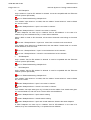
Contents
PACiS System Configuration Editor
SCE/EN T/C80
Page 1/2
PACiS SCE
TECHNICAL GUIDE
CONTENTS
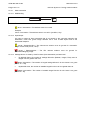
Safety & Handling
Introduction
SCE/EN SA/C80
SCE/EN IT/C80
Technical Data
SCE/EN TD/C80
Functional Description
SCE/EN FT/C80
Installation
SCE/EN IN/C80
Settings
SCE/EN ST/C80
Commissioning Record Sheet
SCE/EN RS/C80
Maintenance
SCE/EN MF/C80
Problem Analysis
SCE/EN PR/C80
Lexical
SCE/EN LX/C80
SCE/EN T/C80
Page 2/2
Technical Guide
Contents
PACiS System Configuration Editor
BLANK PAGE
Safety & Handling
SCE/EN SA/C80
PACiS System Configuration Editor
SAFETY & HANDLING
Safety & Handling
SCE/EN SA/C80
PACiS System Configuration Editor
Page 1/8
CONTENT
1.
INTRODUCTION
3
2.
SAFETY
4
2.1
Health and Safety
4
2.2
Explanation of symbols and labels
4
2.3
Installing, Commissioning and Servicing
4
2.4
Decommissioning and Disposal
4
3.
GUARANTEES
5
4.
COPYRIGHTS & TRADEMARKS
6
4.1
Copyrights
6
4.2
Trademarks
6
5.
WARNINGS REGARDING USE OF SCHNEIDER ELECTRIC
PRODUCTS
7
SCE/EN SA/C80
Page 2/8
Safety & Handling
PACiS System Configuration Editor
BLANK PAGE
Safety & Handling
PACiS System Configuration Editor
1.
SCE/EN SA/C80
Page 3/8
INTRODUCTION
This document is a chapter of PACiS System Configuration Editor PACiS SCE V4.8
documentation. It describes the safety, handling, packing and unpacking procedures
applicable to PACiS SCE software tools.
SCE/EN SA/C80
Safety & Handling
Page 4/8
2.
SAFETY
WARNING:
2.1
PACiS System Configuration Editor
THIS SAFETY SECTION SHOULD BE READ BEFORE COMMENCING
ANY WORK ON THE EQUIPMENT.
Health and Safety
The information in the Safety Section of the product documentation is intended to ensure
that products are properly installed and handled in order to maintain them in a safe condition.
It is assumed that everyone who will be associated with the equipment will be familiar with
the contents of the Safety Section and all Safety documents related to the PC and
Communication networks.
2.2
Explanation of symbols and labels
The meaning of symbols and labels may be used on the equipment or in the product
documentation, is given below.
2.3
Installing, Commissioning and Servicing
Equipment operating conditions
The equipments (PC supporting PACiS SCE) should be operated within the specified
electrical and environmental limits.
Fibre optic communication
Optical LED transceivers used in Switch boards are classified as IEC 825-1 Accessible
Emission Limit (AEL) Class 1 and consequently considered eye safe.
Optical power meters should be used to determine the operation or signal level of the device.
2.4
Decommissioning and Disposal
Disposal:
It is recommended to avoid incineration and disposal of the PACiS SCE CD-ROM. The
product should be disposed of in a safe manner.
Safety & Handling
PACiS System Configuration Editor
3.
SCE/EN SA/C80
Page 5/8
GUARANTEES
The media on which you received Schneider Electric software are warranted not to fail
executing programming instructions, due to defects in materials and workmanship, for a
period of 90 days from date of shipment, as evidenced by receipts or other documentation.
Schneider Electric will, at its option, repair or replace software media that do net execute
programming instructions if Schneider Electric receive notice of such defects during the
guaranty period. Schneider Electric does not guaranty that the operation of the software shall
be uninterrupted or error free.
A Return Material Authorisation (RMA) number must be obtained from the factory and clearly
marked on the package before any equipment acceptance for guaranty work.
Schneider Electric will pay the shipping costs of returning to the owner parts, which are
covered by warranty.
Schneider Electric believe that the information in this document is accurate. The document
has been carefully reviewed for technical accuracy. In the event that technical or
typographical errors exist, Schneider Electric reserves the right to make changes to
subsequent editions of this document without prior notice to holders of this edition. The
reader should consult Schneider Electric if errors are suspected. In no event shall
Schneider Electric be liable for any damages arising out of or related to this document or the
information contained in it.
Expect as specified herein, Schneider Electric makes no guaranties, express or implied and
specifically disclaims and guaranties of merchantability or fitness for a particular purpose.
Customer's rights to recover damages caused by fault or negligence on the part
Schneider Electric shall be limited to the amount therefore paid by the customer.
Schneider Electric will not be liable for damages resulting from loss of data, profits, use of
products or incidental or consequential damages even if advised of the possibility thereof.
This limitation of the liability of Schneider Electric will apply regardless of the form of action,
whether in contract or tort, including negligence. Any action against Schneider Electric must
be brought within one year after the cause of action accrues. Schneider Electric shall not be
liable for any delay in performance due to causes beyond its reasonable control.
The warranty provided herein dues net cover damages, defects, malfunctions, or service
failures caused by owner's failure to follow the Schneider Electric installation, operation, or
maintenance instructions; owner's modification of the product; owner's abuse, misuse, or
negligent acts; and power failure or surges, fire, flood, accident, actions of third parties, or
other events outside reasonable control.
SCE/EN SA/C80
Page 6/8
4.
COPYRIGHTS & TRADEMARKS
4.1
Copyrights
Safety & Handling
PACiS System Configuration Editor
Under the copyright laws, this publication may not be reproduced or transmitted in any form,
electronic or mechanical, including photocopying, recording, storing in an information
retrieval system, or translating, in whole or in part, without the prior written consent of
Schneider Electric.
4.2
Trademarks
PACiS, PACiS SCE, PACiS ES, PACiS SCE, PACiS PS and PACiS SCE are trademarks of
Schneider Electric. Product and company names mentioned herein are trademarks or trade
names of their respective companies.
Safety & Handling
PACiS System Configuration Editor
5.
SCE/EN SA/C80
Page 7/8
WARNINGS REGARDING USE OF SCHNEIDER ELECTRIC PRODUCTS
Schneider Electric products are not designed with components and testing for a level of
reliability suitable for use in or in connection with surgical implants or as critical components
in any life support systems whose failure to perform can reasonably be expected to cause
significant injuries to a human.
In any application, including the above reliability of operation of the software products can be
impaired by adverse factors, including -but not limited- to fluctuations in electrical power
supply, computer hardware malfunctions, computer operating system, software fitness,
fitness of compilers and development software used to develop an application, installation
errors, software and hardware compatibility problems, malfunctions or failures of electronic
monitoring or control devices, transient failures of electronic systems (hardware and/or
software), unanticipated uses or misuses, or errors from the user or applications designer
(adverse factors such as these are collectively termed "System failures").
Any application where a system failure would create a risk of harm to property or persons
(including the risk of bodily injuries and death) should not be reliant solely upon one form of
electronic system due to the risk of system failure to avoid damage, injury or death, the user
or application designer must take reasonably steps to protect against system failure,
including -but not limited- to back-up or shut-down mechanisms, not because end-user
system is customised and differs from Schneider Electric testing platforms but also a user or
application designer may use Schneider Electric products in combination with other
products.
These actions cannot be evaluated or contemplated by Schneider Electric; Thus, the user or
application designer is ultimately responsible for verifying and validating the suitability of
Schneider Electric products whenever they are incorporated in a system or application, even
without limitation of the appropriate design, process and safety levels of such system or
application.
SCE/EN SA/C80
Page 8/8
Safety & Handling
PACiS System Configuration Editor
BLANK PAGE
Introduction
SCE/EN IT/C80
PACiS System Configuration Editor
INTRODUCTION
Introduction
PACiS System Configuration Editor
SCE/EN IT/C80
Page 1/6
CONTENT
1.
INTRODUCTION TO PACiS
3
2.
INTRODUCTION TO PACiS GUIDES
4
2.1
Chapters description
4
2.1.1
Chapter Safety (SA)
4
2.1.2
Chapter Introduction (IT)
4
2.1.3
Chapter Functional Description (FT)
4
2.1.4
Chapter Technical Data (TD)
4
2.1.5
Chapter HMI, Local control and user interface (HI)
4
2.1.6
Chapter Installation (IN)
4
2.1.7
Chapter Commissioning record sheet (RS)
4
2.1.8
Chapter Settings (ST)
4
2.1.9
Chapter Maintenance, Fault finding, Repairs (MF)
4
2.1.10
Chapter Problem analysis (PR)
5
2.1.11
Chapter Lexicon (LX)
5
2.2
Operation guide
5
2.3
Technical guide
5
3.
INTRODUCTION TO PACiS SCE APPLICATIONS
6
SCE/EN IT/C80
Page 2/6
Introduction
PACiS System Configuration Editor
BLANK PAGE
Introduction
SCE/EN IT/C80
PACiS System Configuration Editor
1.
Page 3/6
INTRODUCTION TO PACiS
The PACiS range will continue to be expanded. The general features of PACiS will also be
enhanced, as we are able to adopt new technology solutions.
For
up-to-date
information
www.schneider-electric.com
on
any
PACiS
product,
visit
our
website:
SCE/EN IT/C80
Page 4/6
2.
Introduction
PACiS System Configuration Editor
INTRODUCTION TO PACiS GUIDES
This version of the PACiS SCE documentation refers to version PACiS V4.8. The guides
provide a functional and technical description of the PACiS System Configuration Editor PACiS SCE adapted to PACiS V4 (IEC61850 Station Bus) and a comprehensive set of
instructions for the PACiS SCE’s use and application.
PACiS SCE guides is divided into two volumes, as follows:
•
Operation Guide: includes information on the application of the PACiS SCE and a
technical description of its features. It is mainly intended for protection & control
engineers concerned with the selection and application of the PACiS SCE for the
Configuration of PACiS solution or of any of the PACiS equipment.
•
Technical Guide: contains information on the installation and commissioning of the
PACiS SCE, and also a section on fault finding. This volume is intended for site
engineers who are responsible for the installation, commissioning and maintenance of
the PACiS SCE application.
2.1
Chapters description
2.1.1
Chapter Safety (SA)
This chapter contains the safety instructions, handling and reception of electronic equipment,
packing and unpacking parts, Copyrights and Trademarks.
2.1.2
Chapter Introduction (IT)
This is this document containing the description of each chapter of the PACiS SCE guides. It
is a brief introduction to PACiS SCE capabilities.
2.1.3
Chapter Functional Description (FT)
This chapter contains a description of the product. It describes the functions included in
PACiS SCE.
2.1.4
Chapter Technical Data (TD)
This chapter contains the technical data including, accuracy limits, recommended operating
conditions, ratings and performance data.
It also describes environment specification, compliance with technical standards.
2.1.5
Chapter HMI, Local control and user interface (HI)
This chapter contains the operator interface description, Menu tree organisation and
navigation, Setting/configuration software.
2.1.6
Chapter Installation (IN)
This chapter contains the installation procedures.
2.1.7
Chapter Commissioning record sheet (RS)
This chapter provides detailed record sheets to commission PACiS SCE.
2.1.8
Chapter Settings (ST)
This chapter contains the list of the setting with defaults values and range of the PACiS SCE.
2.1.9
Chapter Maintenance, Fault finding, Repairs (MF)
This chapter provides advice on how to identify failure modes, fault codes and describes the
recommended repair actions.
Introduction
PACiS System Configuration Editor
2.1.10
SCE/EN IT/C80
Page 5/6
Chapter Problem analysis (PR)
This chapter provides practical examples of problem solving and company contact
information. It includes all information on the self-checking features and diagnostics of
PACiS SCE.
2.1.11
Chapter Lexicon (LX)
This chapter contains lexical description of acronyms and definitions of the PACiS SCE.
2.2
Operation guide
This guide contains the following chapters:
SA, IT, TD, FT, HI, AP, LX
2.3
Technical guide
This guide contains the following chapters:
SA, IT, TD, FT, IN, ST, RS, MF, PR, LX
SCE/EN IT/C80
Page 6/6
3.
Introduction
PACiS System Configuration Editor
INTRODUCTION TO PACiS SCE APPLICATIONS
The PACiS SCE Applications are mainly defined in the Application chapter (AP) of each
PACiS equipment (MiCOM C264/C264P, PACiS GTW, PACiS OI).
Technical Data
SCE/EN TD/C80
PACiS System Configuration Editor
TECHNICAL DATA
Technical Data
PACiS System Configuration Editor
SCE/EN TD/C80
Page 1/6
CONTENT
1.
SCOPE OF THE DOCUMENT
3
2.
REQUIREMENTS
4
3.
CAPABILITIES
5
SCE/EN TD/C80
Page 2/6
Technical Data
PACiS System Configuration Editor
BLANK PAGE
Technical Data
PACiS System Configuration Editor
1.
SCE/EN TD/C80
Page 3/6
SCOPE OF THE DOCUMENT
This document is a chapter of PACiS System Configuration Editor PACiS SCE V4.8
documentation. It describes the Technical Data (SCE/EN TD) of this set of software
applications.
SCE/EN TD/C80
Technical Data
Page 4/6
2.
PACiS System Configuration Editor
REQUIREMENTS
For the minimum hardware requirements to operate the PACiS SCE application, please refer
to the table that follows:
Type of PC
Standard desktop with CPU Xeon 2.8 GHz
RAM
2048 Mbytes or more
Hard Disk
80 GB - FT32 format or more.
CD-ROM Reader
Operating System
Windows 2003, or Windows XP Professional SP3
Applications
XML parser
Graphics
VGA screen 256 colours minimum, resolution 1024*768 or higher
Optional
Ethernet port, USB port, CD-Writer for database exchange
You can install the SCE on the same PC that has the Operator Interface (OI) and the System
Management Tool (SMT).
Technical Data
PACiS System Configuration Editor
3.
SCE/EN TD/C80
Page 5/6
CAPABILITIES
The capabilities of the PACiS SCE application allow you to define the maximum
configuration of a PACiS project. You can find a description of the capacity limits of the
different devices of a PACiS project in the chapter PACiS SCE/EN MF. Please refer to the
topic, Capacity limits.
SCE/EN TD/C80
Page 6/6
Technical Data
PACiS System Configuration Editor
BLANK PAGE
Functional Description
SCE/EN FT/C80
PACiS System Configuration Editor
FUNCTIONAL DESCRIPTION
Functional Description
PACiS System Configuration Editor
SCE/EN FT/C80
Page 1/10
CONTENT
1.
SCOPE OF THE DOCUMENT
3
2.
PACiS SCE ARCHITECTURE
4
2.1
General Description
4
2.2
Functional Specification
4
2.2.1
PACiS SCE Users
5
2.2.2
PACiS SCE Template & Object
5
2.2.3
Database creation process
6
2.2.4
Version & release
7
2.3
External Interfaces
7
2.4
Human Interface
8
2.4.1
PACiS SCE General Display
8
2.4.2
Working or Docking Window
10
2.4.3
Management under Windows XP
10
SCE/EN FT/C80
Functional Description
Page 2/10
PACiS System Configuration Editor
BLANK PAGE
Functional Description
PACiS System Configuration Editor
1.
SCE/EN FT/C80
Page 3/10
SCOPE OF THE DOCUMENT
This document is a chapter of the PACiS SCE V4.8 documentation. It is the functional description
of PACiS System Configuration Editor software application dedicated to the PACiS system and
sub-systems.
SCE/EN FT/C80
Page 4/10
Functional Description
PACiS System Configuration Editor
2.
PACiS SCE ARCHITECTURE
2.1
General Description
The System Configuration Editor (PACIS SCE) is the central tool in charge to manage the PACiS
system database for the PACiS equipment. The system configuration database contains the
configuration data for the PACiS system equipment:
•
PACiS OI the Operator Interface
•
PACiS SMT the System Management Tool that download Databases
•
PACiS GTW the Tele control gateway
•
MiCOM Computers C264 & C264P
The PACIS SCE allows some authorised personnel to interact with the PACiS system
configuration:
•
modelling of coherent system configuration data: devices, electrical topologies, graphical
mimics, automations
•
generation of configuration data-file for IEC61850 devices of the PACiS project
To generate any equipment database, the PACIS SCE manages:
•
Inner data of the device itself (structure and parameters values)
•
Exchange data of the device with other system devices
•
Exchange data of the device with non-system devices
With the 3rd case, the PACIS SCE manages the communication with all non-PACiS devices with
typically IED or protection devices on Legacy BUS or system network. It is only by the
configuration of communication mapping that PACIS SCE can handle non-PACiS devices.
2.2
Functional Specification
PACiS System Configuration Editor is a tool that:
•
helps in definition/edition of equipment data with specific editors (attribute, mimic,
ISaGRAF) or with queries on configuration
•
generates equipment databases
The definition of data is done firstly by the definition by developer experts of templates or models
of data. These templates are then stored and delivered in PACIS SCE libraries. In a second time,
the models can be loaded and instanced as a clever kind of duplication to create object data
customised to the application case.
When all data of the concrete case are defined, the PACIS SCE generates a coherent set of
databases that can be loaded into each system device.
Functional Description
SCE/EN FT/C80
PACiS System Configuration Editor
2.2.1
Page 5/10
PACIS SCE Users
Control access of an operator is realised through a login and password capture.
Different levels of operators are distinguished depending on its role:
•
Level 1 allows the modification of an existing configuration by adjustment of parameters,
settings or graphical representations. The users of level 1 can also add or remove
elements derived from the user template libraries. They can generate PACiS application
databags. Level 1 users are typically final users.
•
Level 2 allows the modification of an existing configuration by adding or removing
elements derived from the user templates libraries. They can break the links between the
templates and the instantiated objects. Like level 1 users they can generate PACiS
application databags. Level 2 users are Integrators and VARs.
•
Level 3 users have the capability to modify and create new templates derived from the
existing template libraries. They can generate PACiS application databags but also
template libraries. User of level 3 will be all T&D-EAI PACiS specialists.
•
Level 4 users are PACiS SCE experts. They can modify and create the templates directly
from the structural database elements. Their PACIS SCE user level allows also the
management of all template databases and the administration of the structural database.
The level 4 users are the PACiS SCE administrators.
Such categories is only an outline of PACIS SCE users since several of its tools thanks to
specific editors, or report managers, can provided the records needed by other tasks:
commissioning cubicle, mapping extraction, etc.
2.2.2
PACIS SCE Template & Object
A database is basically a collection of persistent data. In the PACIS SCE framework, a database
is a collection of objects. Any object has its specific attributes, organised in categories and
subcategories. The objects are organised in the database by following pre-defined association
rules.
The structural database defines object types and association types. Association types are
hierarchical link types and relation link types between object types. Hierarchical links are
defined for father/child associations. Relation links are defined for other associations, and may
hold attributes. Cardinalities are defined for all associations.
A library database contains templates. A template is a collection of objects/associations
instantiated from the structural database or from others templates.
A configuration database contains objects/associations instantiated from types of the structural
database or from templates. It also contains its own templates, created specifically for the
configuration, or imported from a library database. A configuration database defines all data
needed by system devices to feel up customer application.
All the database elements support internationalisation (multiple languages).
SCE/EN FT/C80
Functional Description
Page 6/10
2.2.3
PACiS System Configuration Editor
Database creation process
To create the database downloaded to system devices, the common way is to:
•
Import a template from an external library into current database (in its template area)
•
Customise the template if needed in DB template area
•
Instantiated the template from template to Object part of the database
•
Feel up predefined attribute known as degree of freedom (for example the name)
•
Generate devices databases
The link between template and instantiated object can be kept. Nevertheless this relation can be
broken for deep object modifications.
During all this creation process, the PACIS SCE does a check of data coherency with its Data
Model. The checks are made with templates and objects. The checks are made during
configuration edition and/or by a check action. They are done on:
•
Attribute input
•
Relation creation
•
Generation
Configuration database
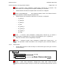
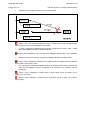
Library = Collection of Models
Local templates
Configuration Objects =
Configuration
Instance 1
Import
Template
Instance 2
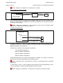
Instance n
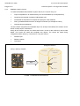
S0126ENa
FIGURE 1: CONFIGURATION PROCESS
Functional Description
SCE/EN FT/C80
PACiS System Configuration Editor
2.2.4
Page 7/10
Version & release
Along time, system’s device features have evolution and their inner data base structure is subject
to modification. PACiS SCE need to feel the new requirement and has also evolutions and
corrections referenced by version.
A unique reference determines the coherent set of system equipment database and soft/hard
equipment that PACIS SCE can be used.
PACIS SCE can be compared two referenced versions of a configuration.
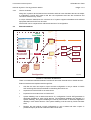
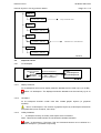
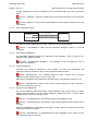
2.3
External Interfaces
PACiS
Data Model
Interface
files
External tools
Xml files
CMT
MiCOM
C264
SMT
OI
ISaGRAF
full integrated
workbenches
SCE
System
databag
FBD
Ga teway
Equipment
Simulator
Configuration
S0469ENa
FIGURE 2: EXTERNAL INTERFACES
There is no software interfaces between PACIS SCE and other external tools or PACiS devices.
External interfaces are implemented through files:
•
Xml files: the user can export or import a whole configuration or only a subset. A PACIS
SCE exchange Xml format is defined for describing files which are:
•
exported from PACIS SCE to an external tool.
•
imported from an external tool to PACIS SCE.
•
System databag: from a referenced version of a configuration, PACIS SCE generates an
application databag for each PACiS devices. The application databags are bagged in a
System databag. The system databag are used by PACiS SMT to download application
databag in each PACiS devices. This system databag could be used by PACiS simulator
tools.
•
Reports: the user selects a whole configuration or only a subset and asks a report. A
predefined report pdf format is delivered with PACIS SCE.
SCE/EN FT/C80
Functional Description
Page 8/10
PACiS System Configuration Editor
NOTES:
All IEC61850 clients must be defined in the SCD file during an export, in
order to know the defined client / server relation(s).
From a SCL point of view, an IEC61850 client is an IED with an “Access
Point” structure without “Server” element.
The MiCOM Px3x / Px4x Phase 2 provide ICD files in which Virtual Inputs
are defined (a Virtual Input is an abstract element which allows to define
an attachment to a GOOSE in MiCOM IED).
The SCE, during an ICD import, creates these Virtual Inputs in a specific
area of the IED IEC61850 mapping. Then, these Virtual Inputs can be
associated to datapoints (using relations) defined in the electrical area.
2.4
Human Interface
2.4.1
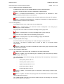
PACIS SCE General Display
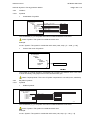
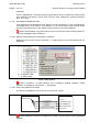
At initial start-up or after installation of new version, the PACIS SCE application display can be
seen as represented below (as far as user has all PACIS SCE rights and licences). It should be
noticed that all parts are not necessary needed for all kind of user.
FIGURE 3: PACiS SCE DISPLAY AT START-UP
The staring view is empty. Explanation of each area is given below with some information on it.
Functional Description
PACiS System Configuration Editor
SCE/EN FT/C80
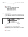
Page 9/10
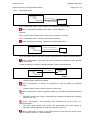
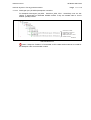
For displaying information it is needed to load a database. After such database load, the PACIS
SCE application looks as below.
FIGURE 4: PACiS SCE DISPLAY WITH LOADED DATABASE
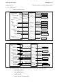
The display is composed of 5 areas:
•
Title Bar
•
Menu Bar
•
Tool Bar
•
Docking Window or common work area composed of several on line optional and
customisable areas.
•
State Bar
SCE/EN FT/C80
Functional Description
Page 10/10
2.4.2
PACiS System Configuration Editor
Working or Docking Window
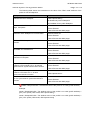
By default or selecting all items in Menu Bar/Windows option items, the working area is displayed
with all areas as below:
FIGURE 5: DOCKING WINDOW
Areas are viewers driven by:
•
Navigator perspective Tree Viewer
•
Mimic Editor
When selecting object (click, enter) all views are “refreshed” with corresponding data:
•
Components List (Object/relations under selected object)
•
Attributes List (of object selected)
•
Template Entry List (of existing template of that can be added under selected object from
DB template list)
•
Object Entry List (of objects that can be added under selected object from conceptual
modeling)
2.4.3
Management under Windows XP
2.4.3.1
Windowing
The PACIS SCE Application follows windowing behaviour. As presented before it has all option
for iconify, maximise/minimise, or close/exit.
When window is minimised it can be resized by its border or corner, and displaced by dragging of
title bar. This behaviour is also down with sub windows.
2.4.3.2
ToolTip
When mouse pointer remains on tool bar icon or menu, a tool tip appears with a short message
explaining the function.
Installation
SCE/EN IN/C80
PACiS System Configuration Editor
INSTALLATION
Installation
SCE/EN IN/C80
PACiS System Configuration Editor
Page 1/28
CONTENT
1.
SCOPE OF THE DOCUMENT
3
1.1
PACiS SCE OUTLINE
3
1.1.1
PACiS SCE Managed System Equipment
3
1.1.2
Version & release
3
2.
REQUIREMENTS
4
2.1
Hardware
4
2.2
PACiS SCE License
4
2.2.1
Scope of Use
5
2.2.2
The Licensee agrees NOT TO:
5
2.2.3
Duration
5
2.2.4
Confidentiality
5
2.2.5
The Licensee SHALL NOT
5
2.2.6
The Licensee SHALL
6
2.2.7
Warranty
6
2.2.8
Limitations of Liability
7
2.2.9
Multi-User
7
2.2.10
General
7
2.3
PACiS SCE delivery package
8
3.
PACiS SCE INSTALL
9
3.1
PACiS SCE Product Install
9
3.1.1
Summary
9
3.1.2
PACiS SCE Detailled Installation Description
9
3.1.3
Check installation
14
3.1.4
PACiS SCE Tool Install: vcredist_X86.exe
14
3.2
PACiS SCE Tool Install: PACiS OI XML Parser
15
3.3
PACiS SCE Tool Install: Configurable Automation ISaGRAF
19
3.4
PACiS SCE Tool Install: Configurable Automation ISaGRAF data access
20
3.5
ISaGRAF upgrade
20
3.6
PACiS SCE Tool Install: Acrobat Reader
21
3.7
PACiS SCE Tool Install: msxml.dll
21
3.8
PACiS SCE Data Bases Libraries Installation
21
3.9
PACIS SCE Tool Install: SCE.lax
21
4.
PACIS SCE UNINSTALL
22
5.
PACIS SCE DATA BASE UPGRADE
23
SCE/EN IN/C80
Page 2/28
Installation
PACiS System Configuration Editor
6.
INSTALLATION OF GROOVY ENVIRONMENT
24
7.
TEST
28
Installation
SCE/EN IN/C80
PACiS System Configuration Editor
1.
Page 3/28
SCOPE OF THE DOCUMENT
This document is a chapter PACiS System Configuration Editor (SCE) V4.8 documentation
binder. It describes the installation of this engineering tool.
An outline helps to define the SCE context. PC requirement for a correct use is then
presented. The installation of SCE and its tools is then given with few necessary setting. The
end of document gives indication for handling install problem or uninstall product.
1.1
PACiS SCE OUTLINE
Schneider Electric’s years of experience in monitoring and control system has learnt that any
system part needs to be highly configurable to match a specific electric substation case, and
its evolution along years. This needed flexibility is not only into the change of parameters
value but also in the structure of data to manage along several devices.
As consequence, system devices use downloaded database compare to fixed devices that
use setting upon a rigid structure of data. The PACiS SCE equipment is the Editor of all data
and the generator creating the Databases for all PACiS equipment.
1.1.1
PACiS SCE Managed System Equipment
PACiS SCE is defined to handle all system structured data and to generate Databases
loaded on PACiS System main equipment:
⇒
PACiS OI the Operator Interface for local HMI
⇒
PACiS SMT the System Management Tool that download Databases
⇒
PACiS ES the Equipment Simulator
⇒
PACiS GTW the separate Tele control Interface to SCADA
⇒
MiCOM C264 & C264PComputers
The tool is designed to be used for several system equipment working together with their
exchange communication data, only one of them. For example it is able to generate
database of one MiCOM C264 used in stand alone.
1.1.2
Version & release
Along time, system’s devices features have evolution and their inner data base structure is
subject to modification. PACiS SCE need to feel the new requirement and has also
evolutions and corrections referenced by version. The software version is seen all along
installation and is expressed for example by:
4.52.3
4: the 1st number is the PACiS system version with fixed features set and Data model
version
52: the 2nd number is an iteration number for the given version (that includes minor evolution)
3: the ending number is optional release on generators.
SCE/EN IN/C80
Page 4/28
2.
Installation
PACiS System Configuration Editor
REQUIREMENTS
PACiS SCE can be installed onto desktop or laptop PC depending of the use of it:
⇒
checking data
⇒
parameter modification
⇒
prototyping substation
⇒
template/model development
⇒
full substation data definition
⇒
equipment database generation
PACiS SCE V4.8 runs on Microsoft XP Pro SP3. There is not special requirement on its
installation.
2.1
Hardware
For data base development purpose, the needed PC is defined with:
⇒
CPU Core II duo 2.66 GHz
⇒
RAM: 2048 GB or more.
⇒
Hard disk: 80 GB with still 40MB free on drive C
⇒
Screen display: 1024*768 resolution minimum
Installation of the package needs an administrator logging.
Stand-alone PACiS SCE version uses less than 200MB but adding documentation and
versioned databases grows quickly the needed space.
2.2
PACiS SCE License
Software Licence Agreement
All programmes and textual works issued by SCHNEIDER Electric SA (hereinafter referred
to as ‘The Supplier’) are protected by copyright. They are supplied on the condition that the
Licensee of copies of such programmes and text agrees to the Terms and Conditions of this
Licence Agreement. The Licensee (which expression includes a purchaser or a receiver of
the Supplier's software on loan) may be held legally liable for any use of the programme(s),
texts or documentation which is not in accordance with this Licence Agreement, in certain
circumstances this may involve criminal prosecution.
The Supplier in consideration of a licence fee paid on its own or as part of a purchase price
and the Licensee's agreement to the Terms and Conditions of their Licence Agreement,
agrees to grant, and the Licensee agrees to accept, a personal, non-exclusive, nontransferable licence to use the Supplier's computer programme(s), text and associated
documentation, all hereinafter referred to as the ‘Licensed Programme’ under the following
Terms and Conditions:
Installation
SCE/EN IN/C80
PACiS System Configuration Editor
2.2.1
Page 5/28
Scope of Use
The Licensee is authorised to use the Licensed Programme in accordance with the Terms
and Conditions of this Licence Agreement for the Licensee's own purposes on any single
computer system that contains no more than one central processing unit (CPU) other than
pursuant to Clause 6 hereof. If the Licensee intends to use the Licensed Programme on
more than one CPU at a time, a separate set of Licensed Programme is required for each
additional CPU. The Licensee may make copies of the Licensed Programme in machine
readable form for back-up and archive purposes only, provided that the Licensee has no
more than three full or partial copies in existence at any one time and that the original
copyright notices and/or other legends are reproduced on each copy. No rights are granted
to the Licensee other than expressed in this Licence Agreement.
2.2.2
2.2.3
The Licensee agrees NOT TO:
1.
Export or re-export the Licensed Programme without the supplier's approval and the
appropriate FRENCH or foreign government licences.
2.
Make, or permit the making of any copy or copies of the Licensed Programme other
than back-up copies permitted under this Licence Agreement.
3.
Reverse compile, reverse engineer, disassemble, modify, adapt, list, print or translate
or otherwise tamper with the whole or any part of the Licensed Programme(s).
4.
Transfer, assign, rent, lease, sell or otherwise dispose of, part with, or share the
possession of the Licensed Programme(s).
Duration
This Licence Agreement becomes effective from the date of the acceptance by the Supplier
of the order for the Licensed Programme and shall remain in force until terminated by the
Licensee. This Licence Agreement will terminate without notice if the Licensee fails to
observe any of the Terms and Conditions of the Licence Agreement. In the event of a
termination, the Licensee agrees to delete the Licensed Programme from any storage media
that are the property of the Licensee and to return all complete and partial copies of the
Licensed Programme together with all copies of text and documentation to the Supplier.
2.2.4
Confidentiality
The Licensed Programme contains confidential information of the Supplier and all copyright,
trade marks and other intellectual property rights in the Licensed Programme are the
exclusive property of the Supplier.
2.2.5
The Licensee SHALL NOT
1.
Save as provided in the Licence Agreement copy the whole or any part of the
Licensed Programme.
2.
Modify, merge or combine the whole or any part of the Licensed Programme with any
other software or documentation.
3.
Use the Licensed Programme on behalf of, or make available the same to, any third
party.
SCE/EN IN/C80
Page 6/28
2.2.6
2.2.7
Installation
PACiS System Configuration Editor
The Licensee SHALL
1.
Keep confidential the Licensed Programme and limit users of the same to those of its
employees agents and sub-contractors who either have a need to know or who are
engaged in the use of the Licensed Programme.
2.
Maintain an up-to-date written record of the number of copies of the Licensed
Programme and their locations and upon request forthwith produce such record to the
Supplier, and
3.
Without prejudice to the foregoing take all such other steps as shall from time to time
be necessary to protect the confidential information and intellectual property rights of
the Supplier in the Licensed Programme.
4.
The Licensee shall inform all relevant employees agents and sub-contractors that the
Licensed Programme constitutes confidential information of the Supplier and that all
intellectual property rights therein are the property of the Supplier and the Licensee
shall take all such steps as shall be necessary to ensure compliance by its employees
agents and sub-contractors within the provisions of this clause.
Warranty
Subject to the exceptions set out in this clause and the limitations upon its liability in Clause
5 below
1.
The Supplier warrants that the media upon which the Licensed Programme is stored
will for a period of 90 days from the date the Supplier accepts an order for a Licensed
Programme be free from defects in material design and workmanship and that the
Licensed Programme will conform to the Supplier's specifications.
2.
Subject to clause 4.3 below the Supplier shall remedy any breach of the above
warranties by the replacement of the Licensed Programme free of charge.
3.
The Supplier shall have no liability to remedy a breach of warranty where such breach
arises as a result of:
4.
−
The improper use, operation, or neglect of the Licensed Programme, or the
computer equipment it is used on.
−
A modification of the Licensed Programme, or its merging in whole or in part with
any other software.
−
Any repair, adjustment, alteration or modification of the Licensed Programme by
any other person than the Supplier, without the Supplier's prior written consent.
Subject to the foregoing, all conditions, warranties, terms and undertakings, express
or implied, statutory or otherwise, in respect of the Licensed Programme are hereby
excluded.
Installation
SCE/EN IN/C80
PACiS System Configuration Editor
2.2.8
Limitations of Liability
1.
The following provisions set out the Supplier's entire liability (including any liability for
the acts and omissions of its employees, agents and sub-contractors) to the Licensee
in respect of any breach of its contractual obligations arising under this agreement and
any representation, statement or tortuous act or omission including negligence arising
under or in connection with this Licence Agreement.
2.
Any act or omission on the part of the Supplier or its employees agents or subcontractors falling within clause 5 above shall for the purposes of this clause be known
as an ‘Event of Default’.
3.
The Supplier's liability to the Licensees for death or injury resulting from its own
negligence or that of its employee’s agents or sub-contractors, shall not be limited.
4.
Subject to the limits set out in clause 5.4 below the Supplier shall accept liability to the
Licensee in respect of damage to the tangible property of the Licensee resulting from
the negligence of the Company or its employees, agents or sub-contractors.
5.
Subject to the provisions of clause 5.3 above the Supplier's entire liability in respect of
any Event of Default shall be limited to damages of an amount equal to:
6.
2.2.9
Page 7/28
−
The case of an Event of Default falling within 5.3 above the purchase price of the
Licensed Programme.
−
The case of any other Event of Default the licence fee paid in respect of the
Licensed Programme.
Subject to clause 5.2 above the Supplier shall not be liable to the Licensee in respect
of any Event of Default for loss of profits, goodwill or any type of special indirect or
consequential loss (including loss or damage suffered by the Licensee as a result of
an action brought by a third party) even if such loss was reasonably foreseeable or the
Supplier had been advised of the possibility of the Licensee incurring the same.
Multi-User
The Supplier in consideration of an enhanced licence fee paid on its own or as part of a
purchase price may authorise the Licensee to use the Licensed Programme simultaneously
on:
2.2.10
1.
Any single computer system that contains up to 5 central processing units (CPUs).
2.
Any single computer system that contains up to 10 central processing units (CPUs).
General
This Licence Agreement overrides all prior written and oral communications regarding the
Licensed Programme with the Licensee, and sets out the entire agreement between the
Supplier and the Licensee. In the event of a dispute between the Supplier and the Licensee
relating to this Licence Agreement, the Licensee agrees to submit to the jurisdiction of the
French Courts or to the Courts of other legal systems that may from time to time be elected
at the sole discretion of the Supplier. If any provision in this Licence Agreement is ruled
invalid under any law, such provision shall be deemed modified or omitted only to the extent
necessary to render it valid and the remainder of this Licence Agreement shall continue in
full force and effect.
SCE/EN IN/C80
Page 8/28
2.3
Installation
PACiS System Configuration Editor
PACiS SCE delivery package
The package can be made by file or CD ROM. The package is composed of :
•
An installer program and its compressed files.
sce_x.y_installer.exe
In addition, depending of the licenses other software and libraries be provided:
−
date bases libraries for substation
*.mpl
−
specific substation database
*.mpc
−
Install CD ISAGRAF Pro from ICS Triplex
Installation
SCE/EN IN/C80
PACiS System Configuration Editor
3.
Page 9/28
PACiS SCE INSTALL
PACiS SCE software installation is decomposed in several parts depending of license
agreement:
⇒
PACiS SCE software
⇒
PACiS SCE Report generating tools (option MSXML)
⇒
PACiS Operator Interface XML Parser (option DB for OI)
⇒
CJ International ISAGRAF Pro for configurable automation (option)
⇒
PACiS SCE Libraries of templates and data bases (option)
After the install few parameter need to be set as described in ST chapter
3.1
PACiS SCE Product Install
The versioned PACiS SCE software is installed via an Installation software. The default
items are the most common.
3.1.1
Summary
Standard installation takes less than 5 minutes. It mainly creates 2 main directories where it
decompresses delivered files:
3.1.2
⇒
C:\ Java\jnrex.y.z with Java n Run Time Engine (or JRE). For instance, j2r1.4.2
⇒
C:\Program files\PACiS\sce\x.y as versioned software product
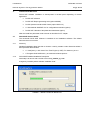
PACiS SCE Detailled Installation Description
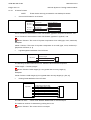
Initial step is to launch with a double click on sce_installer_x.y.exe.
It begins by InstallAnywhere software installation itself.
FIGURE 1 - INSTALLATION OF INSTALLER
SCE/EN IN/C80
Page 10/28
Installation
PACiS System Configuration Editor
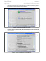
The InstallAnywhere asks then for the appropriate installation language. A scrolling list
shown in Fig 2 helps in selecting it.
FIGURE 2 - SELECTING “INSTALLANYWHERE” INSTALLATION LANGUAGE
After language selection it is proposed to cancel installation or to go head clicking “Next”.
FIGURE 3 - INSTALLANYWHERE INSTALLATION COMPLETED
Installation
SCE/EN IN/C80
PACiS System Configuration Editor
Page 11/28
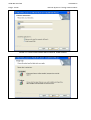
Next screen proposes to accept the terms of the Licence Agreement. Next button is enabled
only if the choice “I accept…” has been done.
FIGURE 4 - LICENCE AGREEMENT
InstallAnywhere software is then installed and proposes the SCE installation. There is no
choice for selecting the directory of Java Real-Time Engine (it is on C:\), but PACiS SCE can
be installed anywhere thanks to a “Choose” option. Nevertheless it seems more appropriate
to use an PACiS directory proposed by default, where other PACiS tools may be installed.
All installation is then done on C: (80MB for SCE 40 MB for JRE libraries that do not change
greatly in time, 150 MB for documentation).
Next screen propose to choose the PACiS SCE software main directory. A subdirectory will
be anyway created, and named sce/x.y (with version reference). From this screen let point
that window header or title has the version installed.
FIGURE 5 - PACiS SCE DIRECTORY SELECTION
SCE/EN IN/C80
Page 12/28
Installation
PACiS System Configuration Editor
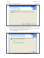
Selecting the Next button leads to define what can be installed. It is proposed a Software,
documentation or Software and Documentation installation.
FIGURE 6 - SELECTION OF INSTALLATION LEVEL
The window below is displayed to summarise the installation parameters before the real
installation: install folder, shortcut folder, JRE installation folder (no choice for user) and disk
space requirement.
FIGURE 7 - PACiS SCE PRE-INSTALLATION SUMMARY
Installation
SCE/EN IN/C80
PACiS System Configuration Editor
Page 13/28
At this stage, all parameters are entered. It remains possible to stop the installation via the
cancel button. The Install button will then start to uncompress in the defined folder.
FIGURE 8 - PACiS SCE INSTALLATION
After a few minutes it is proposed to end the installation clicking on a “Done” button.
FIGURE 9 - PACiS SCE INSTALLATION DONE
SCE/EN IN/C80
Page 14/28
3.1.3
Installation
PACiS System Configuration Editor
Check installation
During installation, Java heap max size is automatically set with 2/3 of ram size, max
1.3 GB.
CARE PRIOR STARTING to read and parameter correctly the equipment as described in
chapter PACiS SCE SETTING.
3.1.4
PACiS SCE Tool Install: vcredist_X86.exe
Always
execute/Install
the
vcredist_X86.exe
file
located
in
("C:\Program
files\PACiS\sce\<SCEVersion>\data\cal\setting\vcredist_x86\vcredist_x86.exe") .If it is not
correctly installed, the setbuilder program to produce the setting files of MiCOM C264 may
not work.
Installation
SCE/EN IN/C80
PACiS System Configuration Editor
3.2
Page 15/28
PACiS SCE Tool Install: PACiS OI XML Parser
If the host PC is used for generating PACiS OI databases, PACiS OI XML Parser is needed.
To proceed, starts by click on:
⇒
\\ <OIVersion> \PROGRAMS\XML Parser\Setup.exe
InstallShield wizard welcome screen appears with its license agreement and installation
options. The standard is “Modify” and “Complete” options.
FIGURE 10 - PACiS OI XML PARSER INSTALLSHIELD, FIRST SCREEN
FIGURE 11 - PACiS OI XML PARSER INSTALLSHIELD, SECOND SCREEN
SCE/EN IN/C80
Page 16/28
Installation
PACiS System Configuration Editor
FIGURE 12 - PACiS OI XML PARSER INSTALLSHIELD, THIRD SCREEN
FIGURE 13 - PACiS OI XML PARSER INSTALLSHIELD, FOURTHS SCREEN
Installation
SCE/EN IN/C80
PACiS System Configuration Editor
Page 17/28
FIGURE 14 - PACiS OI XML PARSER INSTALL
After this InstallShield installation the following screen is displayed.
It is then time to Install PACiS OI XML Parser clicking on install button for a few minute of file
uncompress. The PACiS OI XML Parser is then in directory
⇒
D:\S2K_HMI\XSL
FIGURE 15 - PACiS OI XML PARSER, PLEASE WAIT
SCE/EN IN/C80
Page 18/28
Installation
PACiS System Configuration Editor
FIGURE 16 - PACiS OI XML PARSER, INSTALLATION COMPLETE
FIGURE 17 - RESTART
Restart your computer for a correct running of XML Parser.
Installation
SCE/EN IN/C80
PACiS System Configuration Editor
3.3
Page 19/28
PACiS SCE Tool Install: Configurable Automation ISaGRAF
ISaGRAF PRO is a tool for the definition of automation. This software has a license. Refer to
its installation manual and its separate CD-ROM.
Start on CD-ROM: \\Setup.exe
FIGURE 18 - INSTALL ISaGRAF SELECT LANGUAGE
Select your Language version (for install and help files) than your installation directory when
you have checked licence rights.
FIGURE 19 - INSTALL ISaGRAF SELECT IDIRECTORY
Select a full installation, and accept to reboot the PC.
It may be more appropriate to install it into SCE directory (with other tool).
Set the ISaGRAF path in the menu Tools > Options...
SCE/EN IN/C80
Page 20/28
3.4
Installation
PACiS System Configuration Editor
PACiS SCE Tool Install: Configurable Automation ISaGRAF data access
To compile ISaGRAF project from PACiS SCE and if Microsoft Access 97 is not installed,
you need MS Office 97 ValuPack.
Install the ODBC driver (dataacc.exe) provided in the MS Office 97 Value Pack. You can
download the MS Office 97 Value Pack from:
−
http://www.microsoft.com/ and search for these key words “Office 97 ValuPack”. Make
sure that you spell ValuPack the Microsoft way: it is a registered trademark name.
−
http://www.microsoft.com/downloads/en/details.aspx?familyid=BEFD7842-602E42B0-89D2-6BE39F1167C1&displaylang=en
Office 97 SR-2b is a free update to Office 97, consisting of a series of recent fixes and
designed to make it even easier for customers to deploy Office 97. SR-2b includes currently
available downloads such as the Microsoft Excel 97 for Windows Auto-Recalculation Patch.
3.5
ISaGRAF upgrade
If you have a dongle for ISaGRAF 5.13, you can upgrade it to 5.21.
To do this, install license manager. Then, insert the dongle for 5.13 and launch license
manager. Do this procedure for each dongle, one at a time.
−
Download and install the dongle management software Sentinel Protection on the
ISaGRAF USB dongle. This dongle software is available at:
http://c3.safenet-inc.com/downloads/0/F/0FE57DCB-3A4A-4197-9728EDF352C04562/Sentinel%20Protection%20Installer%207.2.2.exe
−
Install the License Manager application.
−
Insert the dongle for 5.13
−
Start the License Manager application.
−
The License Manager window shows that the dongle is for ISaGRAF 5.1X:
Installation
SCE/EN IN/C80
PACiS System Configuration Editor
Page 21/28
−
Click OK. The License Manager window shows:
−
To claim your upgrade from ISaGRAF Version 5.13 to ISaGRAF Version 5.21, click
Send... The License Manager sends the User codes 1 and 2 to ISaGRAF support:
[email protected]
−
ISaGRAF sends you the Registry keys 1 and 2.
−
Type the Registry keys 1 and 2 in the License Manager. Click Proceed.
−
The Upgrade of the dongle is complete. Remove the dongle.
NOTE:
3.6
The User codes are not regenerated if you change your dongle before
upgrade it.
PACiS SCE Tool Install: Acrobat Reader
Acrobat Reader 5.0 or higher is required to display documentation.
3.7
PACiS SCE Tool Install: msxml.dll
Check the msxml.dll file dates in WINDOWS/system32 folder: if they are different from those
provided in Tools / msxml_dlls.zip file (on PACiS CD), replace them and do not install any
third-party applications after.
3.8
PACiS SCE Data Bases Libraries Installation
There is no real installation of PACiS SCE databases. Databases are files (with extension
mpc or mpl). Any file copy can be used. They are open in run time from PACiS SCE.
3.9
PACIS SCE Tool Install: SCE.lax
To force clean & save during a configuration upgrade, add in SCE.lax:
Dsce.CleanOnUpgrade="true"
To disable the merge of ISaGRAF functions when a PLC contains only one function, add this
line to the file SCE.lax:
Dsce.NoPLCMergeForOneFunction="true"
SCE/EN IN/C80
Page 22/28
4.
Installation
PACiS System Configuration Editor
PACiS SCE UNINSTALL
For all uninstall it is possible to use Windows tools with
“Start-up/Settings/Control panel/Add Remove Programs “ and the selection of:
−
PACiS System Configuration Editor
−
PACiS XML Parser for HMI
−
ISAGRAF PRO
−
…
In the case of PACiS SCE, the Uninstall can be done directly with “Start-up/Application
menu” on item uninstall.
Installation
SCE/EN IN/C80
PACiS System Configuration Editor
5.
Page 23/28
PACiS SCE DATA BASE UPGRADE
In Product life, new version of PACiS SCE may be delivered, with new features, and
corrections. Delivery form or release note should be read carefully because it explains
optional upgrade procedures.
A new PACiS SCE version is installed as explain before. Difference is that during installation,
the software is copied under a new directory with the new PACiS SCE version.
A Database upgrade between two consecutive versions of PACiS SCE is most of the time
made only by starting new PACiS SCE version, and loading the old database. A message
upgrade is displayed. If user saves, the saved database is upgraded to the new PACiS SCE
version.
Between major evolution of the PACiS SCE (first version number is incremented) the
structural database could change. In this case, a special note is added into release note. The
upgrade of the database is then made in 2 main steps.
1.
2.
Export DB from old PACiS SCE version
⇒
Launch old PACiS SCE version
⇒
Open the DB to upgrade
⇒
Menu File/ Prepare Upgrade & Save (save DB with additional data)
⇒
Close this PACiS SCE version
Import DB into new PACiS SCE version
⇒
Launch new PACiS SCE version
⇒
Open the DB
⇒
Save DB changing its name and directory
A good practice is to store DB from a special PACiS SCE version, in a separate directory
that include PACiS SCE DB version and to name DB with PACiS SCE version included.
Anyway other chapters explain automatic controls made on DB.
SCE/EN IN/C80
Page 24/28
6.
Installation
PACiS System Configuration Editor
INSTALLATION OF GROOVY ENVIRONMENT
1.
Install the JAVA JRE version as per SCE Release Note (Download the expected JAVA
JRE version at http://java.com/). It's normally made by the set-up of SCE.
2.
In the Windows Configuration Panel of the SCE machine using the JAVA console
check the system and user JAVA JRE version
FIGURE 20 - JAVA CONSOLE IN THE WINDOWS CONFIGURATION PANEL, JAVA TAB
Installation
PACiS System Configuration Editor
SCE/EN IN/C80
Page 25/28
FIGURE 21 - JAVA CONSOLE IN THE WINDOWS CONFIGURATION PANEL, ACTIVATED SYSTEM
JAVA APPLICATION RUNTIME VERSION (S)
SCE/EN IN/C80
Page 26/28
Installation
PACiS System Configuration Editor
FIGURE 22 - JAVA CONSOLE IN THE WINDOWS CONFIGURATION PANEL, ACTIVATED USER JAVA
APPLICATION RUNTIME VERSION (S)
Installation
SCE/EN IN/C80
PACiS System Configuration Editor
3.
Page 27/28
In the Windows Configuration Panel using the JAVA console configure JAVA Updates
to never check for updates automatically
FIGURE 23 - JAVA CONSOLE IN THE WINDOWS CONFIGURATION PANEL, NEVER CHECK
FOR UPDATES AUTOMATICALLY
4.
Download the Windows Installer Groovy 1.6 Release at url:
htttp://groovy.codehaus.org/Download
5.
Run the groovy-1.6.0-installer.exe and follow wizard
6.
Run the batch file {PACIS_SCE_DIRECTORY}\ScriptsManager\launchGroovy.bat
7.
Groovy Console appears
SCE/EN IN/C80
Page 28/28
7.
Installation
PACiS System Configuration Editor
TEST
The test strategy consists in creating various scripts dedicated to the various silent mode
commands. Targeted data bases will be standard ones (no import), PCCN ones (XML files
import) and PACIS “d” ones (FCS files import) when available.
Run the script using the command line.
Settings
SCE/EN ST/C80
PACiS System Configuration Editor
SETTINGS
Settings
PACiS System Configuration Editor
SCE/EN ST/C80
Page 1/8
CONTENT
1.
SCOPE OF THE DOCUMENT
3
2.
PACiS SCE SETTING
4
2.1
Setting PC memory
4
2.2
PACiS SCE Online Path Setting
4
2.3
PACiS SCE settings import
7
3.
REGITRY KEYS
8
SCE/EN ST/C80
Page 2/8
Settings
PACiS System Configuration Editor
BLANK PAGE
Settings
PACiS System Configuration Editor
1.
SCE/EN ST/C80
Page 3/8
SCOPE OF THE DOCUMENT
This document is a chapter of PACiS System Configuration Editor PACiS SCE V4.8
documentation. It describes the Settings -or on-line- parameters, which can be modified in
runtime PACiS SCE or during the installation time.
SCE/EN ST/C80
Settings
Page 4/8
2.
PACiS System Configuration Editor
PACiS SCE SETTING
For a better efficiency of the installation part, optimal settings need to be done on:
2.1
•
PACiS SCE configuration file lax
•
PACiS SCE run-time setting
Setting PC memory
To optimize management of PC RAM, it is necessary to adjust Java heap size.
During installation, Java heap max size is automatically set with 2/3 of ram size, max
1.3 GB.
After installation, Java heap max size could be updated manually: modify the parameter
lax.nl.java.option.java.heap.size.max (bytes) in file sce.lax. This parameter
must not exceed 1.3 GB. File sce.lax is in the installation directory.
After ram size updating (add or remove ram), run script UpdateLaxFile.vbs in install
directory: this script updates Java heap min size with 32 MB and max size with 2/3 of new
ram size, max 1.3 GB..
NOTE:
2.2
Some PC BIOS does not allow to assign more than 1,25 GB to a
single application. Check with your PC technical document before
setting the PC memory in the sce.lax.
PACiS SCE Online Path Setting
After its installation, PACiS SCE needs its external tools paths. This is done with PACiS
SCE, on line.
Start it via “Start Menu” application launcher:
Programs/PACiS/Configuration Editor x.y/SC
Into PACiS SCE window select in menu bar the “Tools/Options…” item.
Settings
SCE/EN ST/C80
PACiS System Configuration Editor
Page 5/8
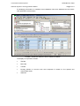
FIGURE 1 - PACiS SCE SETTING AFTER INSTALL
A window “Setting Manager” opens with all PACiS SCE settings.
The optionally installed tool paths have to be entered. Their values must be updating
according to their installation folders. It is especially the case for:
•
ISaGRAF Workbench path setting: the installation folder of ISaGRAF tool.
•
Acrobat Reader Application path: the binary file path of Acrobat Reader.
SCE/EN ST/C80
Page 6/8
Settings
PACiS System Configuration Editor
The other settings do not depend of other tools or others installations:
•
General part settings: the properties of PACiS SCE (read only).
•
Status bar part settings: the displaying options of status bar.
•
Graphic part settings: the graphical editors (mimic editor, bay mimic editor,…) options.
•
Access part settings: default working paths.
•
Miscellaneous part setting: device generation options or general edition options.
FIGURE 2 - PACiS SCE SETTING MANAGER
Path name can be entered directly, or selection of associate button starts an explorer to
choose directory.
Settings
SCE/EN ST/C80
PACiS System Configuration Editor
2.3
Page 7/8
PACiS SCE settings import
A settings set can be imported from a previous version of PAciS SCE. This operation avoids
modifying default settings after each PACiS SCE installation.
This feature is available through the Import button of PACiS SCE Setting Manager dialog
box.
The folllowing Select dialog box is then displayed. A settings file of a previous PACiS SCE
version must be chosen.
FIGURE 3 - PACiS SCE SETTING IMPORT
After its selection, the settings of the opened PACiS SCE are updated with theses settings.
SCE/EN ST/C80
Settings
Page 8/8
3.
PACiS System Configuration Editor
REGITRY KEYS
The PACiS SCE application records a registration key:
HKEY_LOCAL_MACHINE\SOFTWARE\...\PACIS\System Configuration Editor\4.8
NOTE:
For the complete path access of registry key, please consult the
Schneider Electric technical support if needed.
which has the following strings value:
Name
Type
InstallDir
REG_Z
Data
C:\Program Files\PACiS
Usage
Where to find the SCE
executable
This key is issued by the installation procedure of a patch to erase files of an already
installed version.
Record Sheet
SCE/EN RS/C80
PACiS System Configuration Editor
RECORD SHEET
Record Sheet
PACiS System Configuration Editor
SCE/EN RS/C80
Page 1/6
CONTENT
1.
SCOPE OF THE DOCUMENT
3
2.
WORKSTATION CHARACTERISTICS
4
2.1
PC Characteristics
4
2.2
OS Characteristics
4
3.
INSTALLATION
5
3.1
Software Delivery
5
3.2
PACiS SCE Installation
5
3.2.1
General Installation
5
3.2.2
Optional Installations
5
3.3
Installation checking
6
3.3.1
General Checking
6
3.3.2
Settings Checking
6
SCE/EN RS/C80
Page 2/6
Record Sheet
PACiS System Configuration Editor
BLANK PAGE
Record Sheet
PACiS System Configuration Editor
1.
SCE/EN RS/C80
Page 3/6
SCOPE OF THE DOCUMENT
This document is a chapter of PACiS System Configuration Editor PACiS SCE V4.8
documentation. It describes the Commissioning record sheet and the Setting Record (RS) of
this PACiS SCE.
SCE/EN RS/C80
Page 4/6
2.
WORKSTATION CHARACTERISTICS
2.1
PC Characteristics
PC Name
Clock Frequency (GHz)
RAM Size (MB)
DD Size (MB)
2.2
OS Characteristics
WINDOWS XP SERVICE PACK
Record Sheet
PACiS System Configuration Editor
Record Sheet
SCE/EN RS/C80
PACiS System Configuration Editor
3.
INSTALLATION
3.1
Software Delivery
PACiS SYSTEM VERSION
PACiS SYSTEM Release Note Checked:
Yes
No
PACiS SCE VERSION
PACiS SCE Release Note Checked:
Yes
No
3.2
PACiS SCE Installation
3.2.1
General Installation
PACiS SCE Installed using PACiS SCE IN Manual:
Yes
No
PACiS SCE Installation directory:
Standard (C:\Program Files\PACiS\SCE)
Other (precise):
___________________________
PACiS SCE Installation Choice:
Complete (Software & Documentation)
Documentation
Software
PACiS SCE Installation problem:
Yes
No
3.2.2
Optional Installations
Crystal Report Installation
Yes
No
PACiS OI XML Parser Installation
Yes
No
PACiS OI XML Parser VERSION
Automation ISaGRAF data access Installation (if MS access 97 is not installed)
Yes
No
Page 5/6
SCE/EN RS/C80
Page 6/6
Record Sheet
PACiS System Configuration Editor
ISaGRAF PRO Installation
Yes
No
ISaGRAF PRO VERSION
3.3
Installation checking
3.3.1
General Checking
Check that the following files or directories are in the correct path (cf. PACiS SCE IN
Manual):
SCE version directory
j2re (java directory)
msxml.dll file dates in WINNT/system32 folder: they must be identical with those
provided in Tools/ msxml_dlls.zip file (on PACiS CD)
ISaGRAF (optional)
Check that the following items are in the Start Menu:
PACiS SCE
ISaGRAF PRO (optional)
3.3.2
Settings Checking
SCE.lax setting values: open SCE.lax file and report the following values:
lax.nl.java.option.java.heap.size.max
PACiS SCE launched:
Yes
No
Check in PACiS SCE setting manager (Menu Tools, Options) the following values:
JDK’s version
PACiS SCE’s version
Maintenance
SCE/EN MF/C80
PACiS System Configuration Editor
MAINTENANCE
Maintenance
PACiS System Configuration Editor
SCE/EN MF/C80
Page 1/112
CONTENT
1.
SCOPE OF THE DOCUMENT
3
2.
CHECKS
4
2.1
Check user interface
4
2.2
Graphic symbols used in this document
5
2.3
General checks
6
2.3.1
Internal error
6
2.3.2
Objects in Temporary area
6
2.3.3
Capacity limits
6
2.3.4
Variant attributes value
7
2.3.5
Relations
7
2.3.6
Templates
9
2.4
System checks
9
2.4.1
TCP/IP definition on Ethernet Network
9
2.4.2
SNTP servers
10
2.4.3
IEC61850 Physical Devices
10
2.4.4
Wave Records of MiCOM C264s
25
2.4.5
Channels
27
2.4.6
Legacy Networks
28
2.4.7
SCADA Networks
35
2.4.8
Taking Control function
41
2.4.9
Non PACiS IED on IEC61850
43
2.5
Electrical checks
43
2.5.1
Bay and Bay Mimic
43
2.5.2
Switchgear
44
2.5.3
Circuit Breaker
44
2.5.4
Automation Input/Output Plugs
46
2.5.5
Tap Changer
51
2.5.6
AutoRecloser function
52
2.5.7
Synchrocheck function
54
2.5.8
ATCC function
56
2.5.9
Protection module
57
2.5.10
Topology
58
2.5.11
Fast Load Shedding
58
2.5.12
Load shedding/ Load Curtailement
58
2.5.13
I²t function
58
2.5.14
AVR Function
59
SCE/EN MF/C80
Page 2/112
Maintenance
PACiS System Configuration Editor
2.6
Graphical checks
61
2.6.1
O I Workspace
61
2.6.2
OI Window
62
2.6.3
OI Mimic
63
2.6.4
Bay Mimic symbols
63
2.6.5
Standard Command Banner
65
2.6.6
OI symbols
65
2.6.7
Bitmaps
70
2.6.8
Alarm Groups
73
2.6.9
User Profile
73
2.6.10
Memo
74
2.7
Datapoints checks
75
2.7.1
Datapoint Profiles
75
2.7.2
Acquisition / Control Source definition
79
2.7.3
Client / Server definition
85
2.7.4
Datapoints constraints
98
Maintenance
PACiS System Configuration Editor
1.
SCE/EN MF/C80
Page 3/112
SCOPE OF THE DOCUMENT
This document is a chapter of PACiS System Configuration Editor PACiS SCE V4.8
documentation. It describes the Maintenance and Fault Finding procedures of the product. It
is the chapter Maintenance (SCE/MF EN) of the PACiS SCE.
SCE/EN MF/C80
Maintenance
Page 4/112
2.
PACiS System Configuration Editor
CHECKS
This section presents the list and the corresponding explanation of the error/warning
messages you can get into the checks tab of the log window.
Theses errors or warning are raised during the complete consistency check of the current
configuration. The check function is available via menu item file/check (shortcut F6).
Checks are performed according to the following steps:
−
General checks
−
System checks
−
Electrical checks
−
Graphical checks
−
Datapoints checks
Spare objects are not processed.
Objects in Temporary area are not processed.
Referenced document is SCE Check Specification-DSL2-Issue B1.
2.1
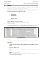
Check user interface
The system displays check traces in the following table of the Traces panel ("Checks" tab):
CHECK RESULT TABLE
Table rows:
−
Each row corresponds to one check operation whose result is an error or a warning or
information.
Table columns:
−
First column:
The user can check On/Off this column to remember which error/warning he tried to
correct.
−
Level:
Icon of error, warning or info.
−
Code:
Identifier of the error, warning or info message. Each code and its level are defined
below.
−
Type:
Identifier of the check operation.
Example: "CircuitBreaker" is a check consisting in verifying the configuration of a
Circuit breaker (missing datapoints, … ).
Maintenance
SCE/EN MF/C80
PACiS System Configuration Editor
Page 5/112
−
Reference:
For each check operation, an Object implicated in the check operation, is considered
as the main Object. The column displays the external Id of this Object. If the user
activates the "Reach" action on the row, this Object is retrieved in the SCE browsers
and selected.
−
Message:
It displays a message explaining the error/warning/info for the check operation.
The panel of the Table contains also the following buttons:
2.2
−
Errors filter toggle button:
If the button is selected, the Error traces are not displayed (they are filtered). Else they
are.
−
Warnings filter toggle button:
If the button is selected, the Warning traces are not displayed (they are filtered). Else
they are.
−
Info filter toggle button:
If the button is selected, the Info traces are not displayed (they are filtered). Else they
are.
−
Checked traces filter toggle button:
If the button is selected, the Checked traces are not displayed (they are filtered). Else
they are.
Graphic symbols used in this document
Check messages are written here with the following indications:
) or Warning (
⇒
the Error (
⇒
the error or warning code
⇒
the check identification
⇒
the check message
) flag
The User Interface of the check table is described in the User Manual of the SCE.
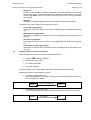
Relation and Attribute representation in figures:
⇒
A relation is marked with a (R).
In the example below, the "Feeder" is linked to the MiCOM C264 bay computer by
the "is managed by" relation.
Feeder
(R) is managed by
C264
S0218ENa
⇒
An attribute is marked with a (A).
In the example below, the "spare" attribute of the "Feeder" is set to the "No" value.
Feeder
(A) spare
No
S0219ENa
The configuration of Relations and Attributes is described in the User Manual of PACiS SCE.
SCE/EN MF/C80
Maintenance
Page 6/112
PACiS System Configuration Editor
2.3
General checks
2.3.1
Internal error
In case of an exceptional error, internal to the check process, the stack trace is displayed
with the following message:
00001 / CheckAbort / Check internal error
2.3.2
Objects in Temporary area
The temporary area must not contain any object which is not spare.
01002 / TemporaryObjects / There are objects in temporary area
2.3.3
Capacity limits
The two following lists are taken from the document PS01.
Component
Maximum authorised
OI client on a per OI server basis
(1)
8
OI server
1+ 1 redundant
Printers OI level
4 (* 2 if redundant)
Printers computer level
(1)
C264/C264C/C264P: 1
IED on a per Legacy Bus basis
(1)
16
IEC equipments (Computers and Generic IEDs)
96
SCADA Networks in the system
16
For a whole PACiS system
Logical Plant Item
Maximum authorised
Substation (1)
40
Voltage Level
4 if ATCC used
Bays
512
Circuit breakers
(XCBR)
Disconnectors
(SWIT)
Transformers
(TXF)
512
2048
(2)
512
Generic modules
4096
Datapoints
48000
Digital Input Points
(SPS, DPS, MPS)
37500
Measurements
(MV)
7500
Counter
512
TPI
512
Output Control Points (SPC, DPC)
5000
Setpoint Outputs (digital or analogue)
512
Run Report
255
LSP data point
300
(1)
Locked by the Structural Database.
(2)
The Structural Database locks the count of Transformers per Bay-Transformer to 1.
So the maximum count of Transformers follows the count of Bay-Transformers.
Maintenance
SCE/EN MF/C80
PACiS System Configuration Editor
Page 7/112
Additional checks:
The check of the count of Symbols per "Comp. workspace" and per "Bay mimic" is described
in section 2.6.4.1Symbols.
02003 / CapacityLimits / The count of … components is not valid (count, maximum)
Examples:
02003 / CapacityLimits / The count of OI server components is not valid (count, maximum)->
[3, 1]
2.3.4
Variant attributes value
NOTE:
These checks are not processed for backup devices.
An attribute value can be dependent of another attribute value.
In the following example, the "C26x SCADA Prot." has 2 attributes: "protocol" and "address
structure".
The set of possible values for "address structure" depends on the selected value for
"protocol".
C264
C26x SCADA Prot
(A) protocol
depends of
- T101
- DNP3
- T104
(A) address structure
- Address on 8 bits (1 byte)
- Address on 16 bits (2 bytes)
- Address on 8 bits.8 bits
- Address on 8 bits.16 bits
- Address on 16 bits.8 bits
- Address on 8 bits.8 bits.8 bits
- Address on 24 bits (3 bytes)
S0220ENa
At the User Interface, the modification of the "protocol" value may lead to an incompatible
"address structure" value.
06101 / AttributeValue / The attribute value is not valid
Example:
06101 / AttributeValue / The attribute value is not valid-> [Scs | Ethernet network | C264 |
C26X SCADA prot | address structure]
2.3.5
Relations
NOTE:
These checks are not processed for backup devices.
The check of a relation depends on its definition in the Structural Database.
•
A "Mandatory" flag is set to NO on a relation for which the link can be omitted.
Object
(R)
Relation
Mandatory = NO
link
No link
OR
Spare link
S0221ENa
If the relation is not linked, then the following message is displayed:
03008 / RelationLinkNull / The optional relation has no link
Examples:
03008 / RelationLinkNull / The optional relation has no link-> [Site | Substation | Voltage level
| Feeder | has for lock right: <null>]
SCE/EN MF/C80
Maintenance
Page 8/112
PACiS System Configuration Editor
If the relation is linked to a spare object, then the following message is displayed:
04010 / RelationLinkSpare / The optional relation has a spare link
Examples:
04010 / RelationLinkSpare / The optional relation have a spare link-> [Site | Substation |
Substation DPC | has for AutoManu dependency: Substation DPS]
Some optional relations may have a specific rule which doesn’t produce a warning if not
filled. These rules are listed below:
−
C26x SCADA protocols have the relation with a “main comm. port” which hasn’t to be
filled in case of T104 protocol,
−
GHU200 Boards have a relation with a workspace which hasn’t to be filled when HMI
type is Simple.
A "Mandatory" flag is set to YES on a relation for which the link is mandatory.
Object
(R)
Relation
Mandatory = YES
link
No link
Or
Spare link
S0222ENa
If the relation is not linked, then the following message is displayed:
03007 / RelationLinkNull / The mandatory relation has no link
This check is not treated if the relation is:
−
a UCA2 addressing relation
−
a “UserFunction_RunsOn_PLC” of an Interlock FBD that belongs to a bay managed
by an IED 61850 no PACiS
Examples:
03007 / RelationLinkNull / The mandatory relation has no link-> [Site | has for Bypass right:
<null>]
If the relation is linked to a spare object, then the following message is displayed:
04009 / RelationLinkSpare / The mandatory relation has a spare link
Examples:
04009 / RelationLinkSpare / The mandatory relation have a spare link-> [Site | Substation |
Substation DPC | has for profile: DPC profile]
−
If a filter is defined for a relation, the link must be compatible with the filter definition.
Object
(R)
Relation
Filter
link
link ∉ Filter
S0223ENa
05011 / RelationLinkFilter / The relation link is not compatible with the filter
Examples:
05011 / RelationLinkFilter / The relation link is not compatible with the filter-> [Site |
Substation | Voltage level | Feeder 1 | circuit breaker | Comp. swit. pos. | 'open' wired on: DI
# 0]
Maintenance
SCE/EN MF/C80
PACiS System Configuration Editor
2.3.6
Page 9/112
Templates
The goal of these checks is to warn user about template coherency. For templates, check if
all components are present in all instances or clones.
This check indicates the template and instance concerned, and the component which are
missing. If the component is a template clone, indicate only the main template.
The way to correct this error is to delete the missing component in the template and to
recreate it.
68213 / Templates / One instance of the template is not coherent with the template
definition (Template, Instance, missing component)
Example:
68213 / Templates / One instance of the template is not coherent with the template definition
(Template, Instance, missing component) -> [Site-Feeder-Feeder1 | Feeder1, Site |
Substation | Voltage level | Feeder 1, Circuit breaker]
68215 / Templates / One instance of the template is not coherent with the template
definition, a root component is missing (Template, Instance, missing component)
A template can only use 1 sub-level of template, i.e. a maximum level of inner template is 2.
68254 / Templates /Number of inner templates reached (number, maximum)
2.4
System checks
2.4.1
TCP/IP definition on Ethernet Network
Each device connected to an Ethernet Network has 2 attributes "TCP/IP address" and
"network name".
⇒
The "TCP/IP address" value of a device, must be unique among all the devices per
Ethernet Network.
⇒
The "network name" value of a device, must be unique among all the devices per
Ethernet Network.
⇒
The network name (alias TCP/IP) must not be reserved by operating system.
Exception:
The unicity is not required between an OI server and an OI client embedded in the same
physical device. Therefore, if an "OI client" is linked to an "OI server" through the relation
"has for HMI server", then it's not checked.
07012 / TCPIPattribute / The attribute value is not unique
Examples:
07012 / TCPIPattribute / The attribute value is not unique-> [TCP/IP address,
255.255.255.255]
07012 / TCPIPattribute / The attribute value is not unique-> [network name, NW_NAME]
07164 / TCPIPattribute / The network name is reserved by operating system
SCE/EN MF/C80
Maintenance
Page 10/112
2.4.2
PACiS System Configuration Editor
SNTP servers
On SCS object, it is possible to configure the TCP/IP addressing for SNTP server (primary
and auxiliary addresses).
This addresses may reference an existing device in database or a devices outside the
PACiS system.
Some rules must be followed for these addresses.
If one of both IP addresses is configured and represent a PACiS device, this device must be
a computer.
07249 / TCPIPattribute / The PACiS SNTP server must be a computer (IP address,
device)
If auxiliary IP address is configured primary address must be configured too.
07250 / TCPIPattribute / The primary SNTP address must be configured if auxiliary is
configured
Primary and auxiliary addresses must be different when configured.
07251 / TCPIPattribute / The two SNTP addresses must be different (IP address)
If the SNTP server (main or auxiliary) is a computer, the datapoint “External clock status” is
mandatory for it:
07292 / TCPIPattribute / The datapoint “External clock status” is required on the
computer running a SNTP server service
2.4.3
IEC61850 Physical Devices
2.4.3.1
Redundancy
2.4.3.1.1 PACiS redundancy
C264 (main)
(R) has for backup
C264 (backup)
(R) is backup of
C264C (main)
(R) has for backup
C264C (backup)
(R) is backup of
OI server (main)
(R) has for backup
OI server (backup)
(R) is backup of
S0225ENa
•
For a device, the relations "has for backup" and "is backup of" are mutually exclusive.
30044 / Redundancy / The relation types are not compatible-> [has for backup, is backup
of]
A main and its backup must be devices of the same type.
30073 / Redundancy / The main and the backup are not of the same type
Examples:
30073 / Redundancy / The main & the backup are not of the same type-> [OI server, C264]
Maintenance
SCE/EN MF/C80
PACiS System Configuration Editor
Page 11/112
2.4.3.1.2 C264 Standalone redundancy
Redundancy of a C264R is managed by the attribute “number of masters”. If it is set to 2, it is
considered as redundant.
A redundant C264 Standalone mustn’t manage Isagraf or FBD functions.
•
78267 / C264R / A redunded C264R mustn’t manage Isagraf or FBD functions.
2.4.3.1.3 Incompatible component for redundant computer
For a redundant C264 the objects that follow are not compatible:
−
TMU 210 Board
30297 / Redundancy / Scs | Ethernet network | C264 | TMU210 / Not compatible
component on a C264 redounded
2.4.3.2
Client - Server relation on IEC61850
NOTE:
•
These checks are not processed for backup devices.
A Client must not be linked to the same Server through multiple relations "has for IEC
server".
C264_1 (client)
(R) has for IEC server
(R) has for IEC client
C264_2 (server)
08013 / RelationClientServer / Multiple links to the same server
Examples:
08013 / RelationClientServer / Multiple links to the same server-> [has for IEC server:
C264_2]
•
Case of "OI server" Client:
The attribute "goose usage", of the relation "has for IEC server", must be set to the "Data
model only" value.
OI server (client)
(R) has for IEC server
(A) modeling / goose usage
OI server 2 (server)
- Data model only
- Goose only
- Data model and Goose
08107 / RelationClientServer / The relation attribute value is not valid. It must be: Data
model only
Examples:
08107 / RelationClientServer / The relation attribute value is not valid. It must be: Data model
only-> [has for IEC server: OI server, modelling/goose usage = Goose only]
•
for a relation client-server with data model usage = data model with or without GOOSE,
a MICOM C264 cannot have more than 10 clients and/or 16 servers. The client-server
relations with GOOSE only are out of the scope of this rule.
SCE/EN MF/C80
Maintenance
Page 12/112
PACiS System Configuration Editor
C264_1 (client)
(R) has for IEC server
C264_2 (server)
(R) has for IEC client
<08141> / RelationClientServer / More than 10 clients for the same computer server
<08140> / RelationClientServer / More than 16 servers for the same computer client
2.4.3.3
IEC61850 Mapping on Ethernet Network
2.4.3.3.1 Mapping definition
NOTE:
These checks are only processed for non-backup devices.
Example of IEC61850Mapping in a Computer:
Ethernet network
C264
c26x IEC Map
IECxLD
GenLN
CO
(A) protocol
IEC 61850
DPCxSBOxS
IEC LD0 - C26x
C26xDIAG
IEC ST for C26xDIAG
AIUSt0
belongs to the list of generic
LogicalDevices of the "c26x IEC Map"
T103 (Legacy Network)
T103_IED
ext IEC Mapping
LDxIED
IEDDIAG
IEC ST IEDDIAG
CommSt
c26x SCADA Prot (SCADA Network)
ext IEC Mapping
IEC LD0 - TCI
TCIDIAG
IEC ST TCIDIAG
CommSt
continuation of
LD0 definition
S0472ENa
•
For each Physical Device on the "Ethernet network":
−
1, and only 1, IEC61850 Mapping, is allowed.
−
this Mapping must be compatible with the value ("IEC61850") set to the "protocol"
attribute of the "Ethernet network".
13110 / EthernetMapping / The component is missing
13109 / EthernetMapping / The component is not allowed
Examples, for an IEC61850 "Ethernet network" protocol:
13109 / EthernetMapping / The component is not allowed-> [C26x IEC Map.]
•
For each Legacy Device on a Legacy Network and, for each SCADA Network:
−
1, and only 1, IEC61850 extended Mapping, is allowed.
−
this extended Mapping must be compatible with the value ("IEC61850") set to the
"protocol" attribute of the "Ethernet network".
13110 / EthernetMapping / The component is missing
Maintenance
SCE/EN MF/C80
PACiS System Configuration Editor
Page 13/112
13109 / EthernetMapping / The component is not allowed
Examples, for an "IEC61850" protocol:
13109 / EthernetMapping / The component is not allowed-> [ext IEC Mapping]
•
For each Logical Device defined under the IEC Mapping:
−
its name must be unique in the mapping. LD name is prefixed by Alias TCP IP and
by IED name (uniquely for legacy IED LD).
−
For PACiS IED, if the Logical Device is a generic one, its name must not contain
the sub-string "LD0" (reserved for system Logical Devices).
Examples:
In the "c26x IEC Map" mapping: "IECxLD" name must be unique among all the generic
Logical Devices of the "c26x IEC Map" + of all the "ext IEC Mapping" of Legacy Devices, and
it must not contain the sub-string "LD0".
13020 / EthernetMapping / The name is not unique
13021 / EthernetMapping / The name is not valid
Examples, for an IEC61850 "Ethernet network" protocol:
13020 / EthernetMapping / The name is not unique-> [LD]
13021 / EthernetMapping / The name is not valid-> [genLD0]
•
For each Brick/LogicalNode defined under a Logical Device:
−
its name must be unique in the Logical Device
Examples:
−
In the "c26x IEC Map" mapping:
"GenLN" name must be unique among all the Logical Nodes of the "IECxLD" Logical
Device.
"C26xDIAG" and "TCIDIAG" names must be unique among all the Logical Nodes of
the "LD0" Logical Device (i.e., among all the Logical Nodes of "IEC LD0 - C26x" + of
"IEC LD0 - TCI").
13020 / EthernetMapping / The name is not unique
•
For each Data Object defined under a Functional Component (CO):
−
its name must be unique in the Functional Component
Examples:
−
In the "c26x IEC Map" mapping:
"DPCxSBOxS" name must be unique among all the Data Objects of the "CO"
Functional Component.
13020 / EthernetMapping / The name is not unique
•
For each Data Object defined under a Functional Component:
−
Only one relation "has for IEC address" is allowed (0 or 1)
27113 / EthernetAddressing / Multiple links
•
For the following Functional Component types of a C264:
−
MX
−
ST
the maximum count of DataObjects is 50.
SCE/EN MF/C80
Page 14/112
Maintenance
PACiS System Configuration Editor
02003 / CapacityLimits / The count of DataObject components is not valid (count,
maximum)
Examples:
02003 / CapacityLimits / The count of DataObject components is not valid (count,
maximum)-> [101, 100]
2.4.3.3.2 IEC Goose
For a given C264, the size of the goose for SPS,DPS, MPS must be less or equal to 1250
bytes. Idem for the size of the goose for measurements and counters.
<54142> / GooseLimits / Goose limit is reached for binary inputs
<54143> / GooseLimits / Goose limit is reached for measurements
For a given C264 the size of the goose for LSP must be less or equal to 3750 bytes.
<54243> / GooseLimits / Goose limit is reached for LSP
In a database, all Goose ID must be unique for a network.
58170 / GooseUnicity / Goose ID (AppID) must be unique for network
2.4.3.3.3 IEC Goose of Functional Components ST or MX
<xxxxx> / Goose ranks contiguous
When a DtObj shows as NOT 'transmitted by goose', its Goose rank sets to an undefined
value or
When there is a gap in the Goose ranks and they are not contiguous as occurs in event of
DtObjs not 'transmitted by goose' any more.
<xxxxx> / Goose ranks identical
When the Goose rank is identical for two DtObjs.
<xxxxx> / Goose ranks not allocated
When some DataObjects have their Goose Rank to 0.
You can fix it using the SCE search with Types= IEC STDataObject (or MXDataObject) and
Attibutes = Goose characteristics
Change the value ‘goose rank’ directly in the table. Please refer to the snapshot that follows.
Maintenance
SCE/EN MF/C80
PACiS System Configuration Editor
Page 15/112
2.4.3.3.4 Addressing of OI printer System Datapoints
OI server
HMI IEC Map.
LD0 for OI
HMIDIAG
ST for HMIDIAG
SOE1St0
SOE1St1
SOE2St0
SOE2St1
SLB1St0
SLB1St1
SLB2St0
SLB2St1
OI printer
System infos
Printer status
BackupPrint stat
OI printer
System infos
Printer status
BackupPrint stat
(A) printer
Sequence of Events
(R) has for IEC address
(R) has for IEC address
SOE∗St∗
SOE∗St∗
(A) printer
Log Book
(R) has for IEC address
(R) has for IEC address
SLB∗St∗
SLB∗St∗
•
If the "OI printer" has its attribute "printer type" set to the "Sequence of Events" value,
then its system Datapoints "Printer status" and "BackupPrint stat." must be linked to an
IEC address named "SOE∗St∗". Only 1 relation is allowed.
•
If the "OI printer" has its attribute "printer type" set to the "Log Book" value, then its
system Datapoints "Printer status" and "BackupPrint stat." must be linked to an IEC
address named "SLB∗St∗". Only 1 relation is allowed.
27050 / EthernetAddressing / The relation link is not valid
27113 / EthernetAddressing / Multiple links
2.4.3.3.5 Addressing of OI client System Datapoints
OI server
HMI IEC Map.
LD0 for OI
HMIDIAG
ST for HMIDIAG
HMISt0
HMISt1
HMISt2
HMISt3
HMISt4
HMISt5
HMISt6
HMISt7
OI client
System infos
OI client link
•
(R) has for HMI server
(R) has for IEC address
HMISt∗
The system Datapoint "OI client link" of an "OI client" must be linked to an IEC address
named "HMISt∗". Only 1 relation is allowed.
27050 / EthernetAddressing / The relation link is not valid
27113 / EthernetAddressing / Multiple links
Example:
27113 / EthernetAddressing / Multiple links-> [has for IEC address : HMISt0]
27113 / EthernetAddressing / Multiple links-> [has for IEC address : HMISt2]
SCE/EN MF/C80
Maintenance
Page 16/112
PACiS System Configuration Editor
2.4.3.3.6 Addressing of Computer boards Status Datapoints
C264
C26x IEC Map.
LD0 for C26x
C26xDIAG
ST for C26xDIAG
DIUSt0
DIUSt1
DIUSt2
DIUSt3
…
(A) physical board number
DIU200
System infos
DIU status
(R) has for IEC address
0
DIUSt0
S0232ENb
The status Datapoint of a Computer board must be linked to an IEC address with a
name matching the board type and ending with the value of the attribute "physical
board number". Only 1 relation is allowed.
•
27067 / EthernetAddressing / The address in not compatible with the board number
Example:
27067 / EthernetAddressing / The address in not compatible with the board number-> [has
for IEC address: DIUSt1, DIU200.physical board number = 0]
2.4.3.4
C264 Boards
NOTE:
These checks are only processed for non-backup Computers.
Count of boards in a C264 computer:
•
A
B
BIU
CPU
1
2
3
4
5
6
7
8
9
10
11
12
13
14
15
Slots from 1 to 14 may contain a board of the following types:
−
AIU200, AIU210, AIU211
−
DOU200
−
DIU2xx
−
CCU20x
−
AOU200
Slot 15 may contain 1 TMU200/TMU210/TMU220 board or 1 board of the above types.
If a TMU200/TMU220 is present, then the maximum count of boards must be ≤ 14
If a TMU210 is present, then the maximum count of boards must be ≤ 13
else the maximum count of boards must be ≤ 15
Count of boards in a C264C computer:
•
A
B
BIU
CPU
1
2
3
4
5
6
Maintenance
SCE/EN MF/C80
PACiS System Configuration Editor
Page 17/112
Slots from 1 to 4 may contain a board of the following types:
−
AIU200, AIU210, AIU211
−
DOU200
−
DIU2xx
−
CCU20x
−
AOU200
Slots 5, 6 may contain 1 TMU200/TMU210/TMU220 board or 2 boards of the above types.
If a TMU200/TMU220 is present, then the maximum count of boards must be ≤ 4
If a TMU210 is present, then the maximum count of boards must be ≤ 3
else the maximum count of boards must be ≤ 6
09144 / ComputerBoards / The count of TMU boards is not valid (count, maximum)
09145 / ComputerBoards / The count of AIU boards is not valid (count, maximum)
09003 / ComputerBoards / The count of Board components is not valid (count,
maximum)
Examples:
09003 / ComputerBoards / The count of Board components is not valid (count, maximum)->
[6, 4]
•
Attribute "physical board number" of a board.
C264
AIU200
DOU200
DIU200
CCU20x
(A) board number
1
S0233ENb
For boards AOU200, AIU201, AIU210, DIU200, DIU210, DOU200, CCU200, the "board
number" attribute values must be unique and contiguous. This board number is a physical
number defined by the user.
For boards DIU211, DOU201, CCU211, (boards managing the slot number) the board
number is a computed logical number. It is unique and contiguous by board type
09015 / ComputerBoards / The attribute value is not unique for the board type
09016 / ComputerBoards / The attribute values are not contiguous for the board type
(board type, attribute)
SCE/EN MF/C80
Maintenance
Page 18/112
PACiS System Configuration Editor
Examples:
09015 /ComputerBoards / The attribute value is not unique for the board type-> [physical
board number, 1]
09016 / ComputerBoards / The attribute values are not contiguous for the board type (board
type, attribute)-> [CCU200, physical board number]
•
Attribute "slot number" of a board managing the slot number.
C264
DIU211
DOU201
CCU211
(A) slot number
C
For boards managing the slot number, the "slot number" attribute values must be unique.
09282 / ComputerBoards / The attribute value is not unique for boards of rack
Example:
09282 / ComputerBoards / The attribute value is not unique for boards of rack -> [slot
number, C]
•
GHU200 board.
The GHU200 board has an attribute "HMI type" and a relation "has for workspace".
C264
GHU200
Led # 4
(A) HMI type
(R) has for workspace
(R) displays state of
- Simple
- Complete
- Old
Graphic
Comp. workspace
SPS
DPS
S0234ENa
−
If the value of the "HMI type" attribute is different from "Complete", then the relation
"has for workspace" must not be linked:
09078 / ComputerBoards / The relation link is not compatible with the board type-> [has
for workspace: Comp. workspace, HMI type = Simple]
−
If the AVR panel is configured, the computer must manage an AVR function:
09304 / Computer Boards / The usage of the AVR panel is allowed only if computer
manage an AVR function
−
If the AVR panel is used as default panel for start or inactive, the AVR panel must be
configured:
09305 / Computer Boards / The usage of the AVR panel as default is allowed only if AVR
panel is configured
If the default panel for start or inactive is Graphical Bay Panel ‘n’, ‘n’ must be lesser or equal
to number of Graphical Bay Panel configured:
09306 / ComputerBoards / The usage of the graphical bay panel 'n' as default is allowed
only if up to 'n' graphical bay panel are configured (number of graphical bay panel) -> [12]
Maintenance
SCE/EN MF/C80
PACiS System Configuration Editor
−
Page 19/112
If the value of the "HMI type" attribute is "Simple", then "Led#5" must not be used (no
relation link from "Led#5" to a Datapoint):
35077 / BoardLeds / The use of this LED is incompatible with the board type (type)->
[HMI type = Simple]
−
If the value of the "HMI type" attribute is "Simple", Led object can’t has “displays state
of ” relation with attribute “Led behaviour” equals to “used for alarm”:
35217 / BoardLeds / The attribute “Led behavoir” on relation “has displays state” can be
“used for alarm” only when GHU200 board is “Complete”.
−
A led can be used by a data point only if this data point is managed by the same
computer than the computer bearing the led:
35227 / BoardLeds / Board led can be use only by data point managed by the led server
−
Only led #14 to led #17 can be used by a data point if the led allocation is set to
predefined at the GHU board level:
35281 / BoardLeds / The use of this LED is incompatible with the predefined led
allocation
•
TMU200, TMU210 and TMU220 boards
These boards are exclusive one another for the same computer.
<09139> / ComputerBoards / TMU200, TMU210 and TMU220 can not belong to the
same computer.
•
TMU210 board
When used, its DO channel can only be wired to the open or close states of the Switch
Control DPC of a breaker.
The DO#1 can be wired on open state and DO#5 on closed state.
09180 / ComputerBoards / DO channels of TMU210 can only be used for open (DO_1)
or close (DO_5) states of the Switch Control DPC of a breaker
When used, the protection function “automatism” is mandatory because the SPS “synthesis
of instantaneous” defined under it is mandatory.
This check is not done for following cases:
- SCE is ‘Poste d’ application (i.e., lax flag sce.Poste_d is set).
- an internal Synchrocheck of type 2 is configured on the SCE
09197 / ComputerBoards / when TMU210 is configured, protection function “automatism”
is mandatory for SPS “synthesis of instantaneous”
•
CPU260/CPU270 board
When ports 3 and 4 are both used, they must have same baud rate.
<09201> / ComputerBoards / Port 3 and 4 of CPU260 must have same baud rate when
used.
•
AOU200 board
When a C264 is configured as redundanct, AOU200 board is not allowed.
<09270> / ComputerBoards / When a computer is redunded, AOU200 board is not
allowed.
SCE/EN MF/C80
Maintenance
Page 20/112
2.4.3.5
PACiS System Configuration Editor
Computer extension racks
NOTE:
•
These checks are only processed for non-backup computers.
Attribute "rack number" of an extension rack.
C264
AIU200
DOU200
DIU20x
CCU20x
(A) physical board number
1
S0233ENa
For the set of the extension racks of a computer, the "rack number" attribute values must be
unique and contiguous.
80279 / Extension rack / The attribute value is not unique for the extension rack
80280 / Extension rack / The rack numbers are not contiguous
2.4.3.6
Computer Settings
NOTE:
This check is only processed for non-backup computers.
A computer has the following attributes:
C264
(A) BI filtering / debouncing delay (ms)
(A) BI filtering / filtering delay (ms)
(A) Measurements / debouncing delay (ms)
(A) Measurements / filtering delay (ms)
(A) Counter / debouncing delay (ms)
(A) Counter / filtering delay (ms)
1
0
1
0
1
0
S0235ENa
For each attribute category (BI filtering / Measurements / Counter), if the attribute
"debouncing delay" is set to value 0, then the attribute "filtering delay" must be set to value 0.
10096 / ComputerSettings / The attribute values are not compatible
Examples:
10096 / ComputerSettings / The attribute values are not compatible-> [BI filtering/deboucing
delay (ms), BI filtering/filtering delay (ms)]
2.4.3.7
Computer Klaxon
NOTE:
This check is only processed for non-backup computers.
A computer may have the following relation:
C264
(R) has its klaxon controlled by
SPC
(R) wired on
C264
DOU200
DO # 0
S0236ENa
The "SPC" link of the relation "has its klaxon controlled by" must be wired on a DO channel
of the Computer.
10033 / ComputerSettings / The relation link is not a wired datapoint
10034 / ComputerSettings / The relation link is not a datapoint wired on the Computer
Maintenance
SCE/EN MF/C80
PACiS System Configuration Editor
Page 21/112
Examples:
10033 / ComputerSettings / The relation link is not a wired datapoint-> [has its klaxon
controlled by: Bay SPC
10034 / ComputerSettings / The relation link is not a datapoint wired on the Computer-> [has
its klaxon controlled by: Bay SPC
2.4.3.8
Computer Printers
NOTE:
•
This check is only processed for non-backup computers.
Log Management attributes of a Serial Printer
C264
Serial printer
(A) buffer size
(A) nb of events to suppress when saturated
1000
300
S0237ENa
The following constraint between the two attributes values must be respected:
"buffer size" > "nb of events to suppress when saturated"
29105 / Printers / buffer size (events) is not greater than nb of events to suppress when
saturated
Examples:
29105 / Printers / buffer size (events) is not greater than nb of events to suppress when
saturated-> [200, 300]
•
Printing format attributes of a Serial Printer
C264
Serial printer
(A) Chronology column rank
(A) Time Stamp column rank
(A) Origin column rank
(A) Object Name column rank
(A) Object Message column rank
1
2
3
4
5
S0238ENa
The value of each "… column rank" attribute must be unique.
29072 / Printers / The column rank is not unique
Example:
29072 / Printers / The column rank is not unique-> [Chronology column rank, Object
Message column rank, Object Name column rank, Origin column rank, Time Stamp column
rank, 1]
SCE/EN MF/C80
Maintenance
Page 22/112
2.4.3.9
PACiS System Configuration Editor
OI server Printers
NOTE:
•
These checks are only processed for non-backup OI servers.
Count of OI Printers for an OI server
OI server
OI printer 1
OI printer 2
OI printer 3
OI printer 4
(A) printer type
(A) printer type
Sequence Of Events
(A) printer type
(A) printer type
Log Book
Sequence Of Events
Log Book
S0239ENa
For an "OI server": the maximum count of OI Printers, typed as "Sequence Of Events", is 2.
For an "OI server": the maximum count of OI Printers, typed as "Log Book", is 2.
29004 / Printers / The count of OI printer components is not valid (type, count, maximum)
Examples:
29004 / Printers / The count of OI printer components is not valid (type, count, maximum)->
[Sequence Of Events, 4, 2]
•
Log Management attributes of an OI Printer
OI server
OI printer
(A) buffer length
(A) recovery length
60
45
S0240ENa
The following constraint between the two attributes values must be respected:
"buffer length" > "recovery length"
29105 / Printers / buffer length (s) is not greater than recovery length (s)
Examples:
29105 / Printers / buffer length (s) is not greater than recovery length (s)-> [60, 61]
•
Printing format attributes of an OI Printer
OI server
OI printer
(A) Chronology column rank
(A) Time Stamp column rank
(A) Origin column rank
(A) Object Name column rank
(A) Object Message column rank
(A) Origin Cat. column rank
(A) Origin Ident. column rank
1
2
3
4
5
0
0
The value of each "… column rank" attribute different than 0 must be unique.
The maximum number of characters by printing line is 154
29072 / Printers / The column rank is not unique
Maintenance
SCE/EN MF/C80
PACiS System Configuration Editor
Page 23/112
Example:
29072 / Printers / The column rank is not unique-> [Chronology column rank, Object
Message column rank, Object Name column rank, Origin column rank, Time Stamp column
rank, 1]
29203 / Printers / The size in character of the printing line is too long
Example:
29203 / Printers / The size in character of the printing line is too long -> [205, 154]
2.4.3.10
OI server Symbols
NOTE :
•
These checks are only processed for non-backup OI servers.
Count of Send Order actions for an OI server
(R) has for HMI Client
OI Server
Oi Client
(R) has for workspace
OI Workspace
Window
Mimic
Symbol
Send Order
S0507ENa
An OI Server can not manage more than 1024 Send Order in all of his mimics.
Count all Send Order of all mimics of all workspaces of all clients of the Server.
Doesn’t treat a workspace twice if set as workspace of two clients.
02003 / CapacityLimits / The count of Send Order components is not valid (count,
maximum)
2.4.3.11
IEC Gen IED data model reference
IEC gen IED
(A) model file name
model.xml
The value of the attribute "model file name" is mandatory.
34101 / DataModelReference / The attribute value is not valid-> [model file name]
2.4.3.12
Cyclic SPS
NOTE:
This check is only processed for non-backup computers.
Up to eight cyclic SPS can be managed per computer basis
59003 / CalculatorCyclicSPS / The count of cyclicSPS components is not valid (count,
maximum)
2.4.3.13
Computer AM Acquisition
For each C264 the delta between Delta between 'long AI scanning cycle' and 'short AI
scanning cycle' must be greater or equals to 500 ms.
76263 / C264 AM Acquisition / Delta between 'long AI scanning cycle' and 'short AI
scanning cycle' must be greater or equals to 500 ms.
SCE/EN MF/C80
Page 24/112
2.4.3.14
Maintenance
PACiS System Configuration Editor
OI Server
•
In Hot Redundancy mode the OI Server must have the datapoint ‘Redundancy Status’
77258 / OI / On OI Server in Hot Redundancy mode datapoints Red.Status must be
present under OI Server.
•
In Hot Redundancy mode, if exist more than one OI Clients exists, each OI Server is
HMI server for at least one OI client
77260 / OI / In Hot Redundancy mode if exist more than one OI Client, each OI Server is
HMI server for at least one OI client.
Maintenance
SCE/EN MF/C80
PACiS System Configuration Editor
2.4.4
Wave Records of MiCOM C264s
NOTE:
2.4.4.1
Page 25/112
These checks are only processed for non-backup MiCOM C264s.
Common check for fast and slow record
for a Fast or a Slow Wafeform, a datapoint can not be configurated more than once for the
same relation (record, trigger and analog channel lists).
•
36195 / WaveRecording / multiple links to the same datapoint -> [external id of the
relation]
A Wave Record can only registrer data point wired physically on the same server tha the
MiCOM C264which mange the Wave Record.
A Wave Record can only registrer data point managed by the same server than the C264
which mange the Wave Record, and not acquire on IED.
36234 / WaveRecording / Data point register by wave record must be managed by
same C264 than wave record C264 and not acquire on IED -> [Path of the record relation]
36246 / WaveRecording / The datapoint 'DREC ready' must be present if a Wave
recording is configured
2.4.4.2
Wave Fast Record
C264
Wave fast record
(A) pre-trigger cycle
(A) total cycles
(A) number of files
0
480 | 240 | 120 | 60
1|2|4|8
S0243ENa
The following constraints between the attributes must be respected:
"pre-trigger cycle" ≤ "total cycles"
"number of files" ∗ "total cycles" ≤ 480 cycles
36102 / WaveRecording / pre-trigger cycle is greater than total cycles
36103 / WaveRecording / number of files * total cycles is not lower than 480
Examples:
36102 /WaveRecording / pre-trigger cycle is greater than total cycles-> [2, 1]
36103 / WaveRecording / number of files * total cycles is not lower than 480-> [8, 480]
2.4.4.3
Wave Slow Record
C264
Wave slow record
(A) pre-trigger cycle
(A) total records
(A) number of files
0
480 | 240 | 120 | 60
1|2|4|8
S0244ENa
The following constraints between the attributes must be respected:
"pre-trigger cycle" < "total records"
SCE/EN MF/C80
Maintenance
Page 26/112
PACiS System Configuration Editor
"number of files" ∗ "total records" ≤ 5000 records
36103 / WaveRecording / pre-trigger cycle is not lower than total records
36102 / WaveRecording / number of files * total records is greater than 5000
Examples:
36103 / WaveRecording / pre-trigger cycle is not lower than total records-> [2, 1]
36102 /WaveRecording / number of files * total records is greater than 5000-> [50, 1000]
The following checks depend on the value of the attribute "electrical frequency":
C264
Wave slow record
(A) Measurements / electrical frequency
(A) integration time
50 Hz
60 Hz
[1..180000]
[1..216000]
(R) records
(R) records
DPC
SPC
DPS
SPS
S0245ENa
•
If "electrical frequency" ≡ 50 Hz:
−
The "integration time" value must be in the range [1..180000].
−
If the "integration time" value is > 5, then no DPC, SPC, DPS, SPS recording is
allowed.
36104 / WaveRecording / integration time is not in the range [1..180000]
36129 / WaveRecording / The relation type is not allowed
Examples:
36104 / WaveRecording / integration time is not in the range [1..180000]-> [180001]
36129 / WaveRecording / The relation type is not allowed-> [records: Bay DPC]
•
If "electrical frequency" ≡ 60 Hz:
−
The "integration time" value must be in the range [1..216000].
−
If the "integration time" value is > 6, then no DPC, SPC, DPS, SPS recording is
allowed.
36104 / WaveRecording / integration time is not in the range [1..216000]
36129 / WaveRecording / The relation type is not allowed
Examples:
36129 / WaveRecording / The relation type is not allowed-> [records: Bay DPC]
A slow wave record is not compatible with a TMU210 board existing on the same MiCOM
C264
36202/ WaveRecording / Slow wave record is not compatible with a TMU210 board usage
2.4.4.4
Triggers of Wave Record
Any trigger datapoint of a given Wave record most have the same server than the MiCOM
C264 managing this wave record.
36223 / WaveRecording / The trigger datapoint has not the same server as its
associated wave record (servers)
Maintenance
SCE/EN MF/C80
PACiS System Configuration Editor
2.4.5
Page 27/112
Channels
Example of relations connecting Legacy Network / SCADA Network / Serial Printer /
Datapoint to a Channel:
C264
DNP3 master (Legacy Network)
(R) has for main comm. port
(R) has for aux. comm. port
C26X SCADA prot (SCADA Network)
(R) has for main comm. port
(R) has for aux. comm. port
C264
BIU200
RS232/485 port 1 (Comm. Channel)
RS232/485 port 2 (Comm. Channel)
(R) has for comm. port
Serial printer
S0246ENa
IEC gateway
Usual protocol (SCADA Network)
GI74 protocol (SCADA Network)
MV
(R) has for main comm. port
(R) has for aux. comm. port
(R) has for main comm.
(R) has for aux. comm. port1
(R) has for main comm. port2
(R) has for aux. comm. port2
(R) has for main comm. port3
(R) has for aux. comm. port3
(R) has for main comm. port4
(R) has for aux. comm. port4
(R) 'bit 00' wired on
(R) 'bit 01' wired on
IEC gateway
Gateway channels
Gateway chan. 1
Gateway chan. 2
Gateway chan. 3
Gateway chan. 4
Gateway chan. 5
Gateway chan. 6
Gateway chan. 7
Gateway chan. 8
( Gateway Channel )
( Gateway Channel )
( Gateway Channel )
( Gateway Channel )
( Gateway Channel )
( Gateway Channel )
( Gateway Channel )
( Gateway Channel )
C264
DIU200
DI#0 (Channel)
DI#1 (Channel)
S0248ENa
A Channel must be used only once.
11017 / RelationHasForCommPort / Multiple links to the same communication port
12018 / RelationHasForChannel / Multiple links to the same channel
Examples:
11017 / RelationHasForCommPort / Multiple links to the same communication port-> [is main
comm. port of: C26X SCADA prot]
12018 / RelationHasForChannel / Multiple links to the same channel-> ['bit 00' channel for:
Bay MV]
The T101-SAS Protocol can’t have an auxiliary communication port.
11252 / RelationHasForCommPort / Auxiliary communication port is not allowed for this
protocol (comm. port)
SCE/EN MF/C80
Maintenance
Page 28/112
PACiS System Configuration Editor
Attribute "plug com. number" of Gateway channels:
IEC gateway
Usual protocol
(R) has for main comm. port
(R) has for aux. comm. port
IEC gateway
Gateway channels
Gateway chan. 1
Gateway chan. 2
Gateway chan. 3
Gateway chan. 4
Gateway chan. 5
Gateway chan. 6
Gateway chan. 7
Gateway chan. 8
(A) plug com. number
1
Under a Gateway, each channel used by a non-GI74 protocol, must have a unique value for
its "plug com. number" attribute.
31019 / GatewayCommPorts / The attribute value is not unique for the gateway
Example:
31019 / GatewayCommPorts / The attribute value is not unique for the gateway-> [plug com.
number, 1]
Attribute "baud rate" of Gateway channel:
Under a Gateway, channel baud rates 100, 200, 38400 are available only for T101 protocol.
31104 / GatewayCommPorts / Baud rate is not in the range [300..19200]
Channel baud rates 100, 200 are also available for SAS protocol.
31104 / GatewayCommPorts / SAS baud rate is not in the range [100..19200]
2.4.6
Legacy Networks
NOTE:
These checks are not processed for Legacy Networks of backup
devices.
The general interrogation period of a T103 acquisition type should be equal to 0 or greater
than 600 s
17276 / LegacyIED / The general interrogation period should be equal to 0 or greater
than 600 s
The port used by a T103 legacy network must have an even parity.
17277 / LegacyIED / Even parity is required for T103 usage on the port
2.4.6.1
IEDs on Legacy Networks
C264
Legacy networks
DNP3 master
DNP3_IED
DNP3_IED
(A) network address
(A) network address
Modbus Mod.
MODB_IED
(A) network address
T103
T103_IED
(A) network address
T101 master
T101_IED
(A) network address
0
0
0
0
0
S0250ENa
Maintenance
SCE/EN MF/C80
PACiS System Configuration Editor
Page 29/112
For each IED, per Legacy Network:
−
its "network address" attribute value must be unique
−
its "short name" attribute value must be unique
17035 / LegacyIED / The address of the IED is not unique on the Legacy Network
17036 / LegacyIED / The name of the IED is not unique on the Legacy Network
Examples:
17035 / LegacyIED / The address of the IED is not unique on the Legacy Network-> [network
address, 0]
17036 / LegacyIED / The name of the IED is not unique on the Legacy Network-> [short
name, DNP3_IED]
C264
Legacy networks
DNP3 master
DNP3_IED
DNP3 acq type
Modbus Mod.
MODB_IED
MODBUS acq type
T103
T103_IED
T103 acq type
T101 master
T101_IED
S0251ENa
For each Device, and for all its Legacy Networks, the maximum count of "xxx acq type"
components is 10.
02003 / CapacityLimits / The count of IED acquisition type components is not valid
(count, maximum)
Examples:
02003 / CapacityLimits / The count of IED acquisition type components is not valid (count,
maximum)-> [11, 10]
SCE/EN MF/C80
Maintenance
Page 30/112
2.4.6.2
PACiS System Configuration Editor
IED Mapping
2.4.6.2.1 Case of DNP3 IED
In the IED Mapping, the address identification of each "xxx addr. on IED" must be unique.
The address identification is the value of the attribute "address" of the "xxx addr. on IED".
DNP3_IED
IED Mapping
IED DPC Mapping
DPC addr. on IED
(A) address
IED DPS Mapping
DPS addr. on IED
(A) address
IED SPC Mapping
SPC addr. on IED
(A) address
1
IED SPS Mapping
SPS addr. on IED
(A) address
2
IED MPS Mapping
MPS addr. on IED
(A) address
3
IED Counter Mapping
Counter addr. on IED
(A) address
IED MV Mapping
MV addr. on IED
(A) address
5
IED SetPt Mapping
SetPt addr. on IED
(A) address
6
0
0
4
S0252ENa
18037 / xxxAddressOnIED / The address of the 'xxx address on IED' is not unique in the
Mapping
Examples:
18037 /xxxAddressOnIED / The address of the 'xxx address on IED' is not unique in the
Mapping-> [address, 0]
Maintenance
SCE/EN MF/C80
PACiS System Configuration Editor
Page 31/112
2.4.6.2.2 Case of MODBUS IED
In the IED Mapping, the address identification of each "xxx addr. on IED" must be unique.
For each "xxx addr. on IED", the address identification is made of the following combinations
of its attribute values:
−
{ "mapping address" , "function" , "bit number" }
−
{ "mapping address" , "function" }
MODB_IED
IED Mapping
IED DPC Mapping
DPC addr. on IED
(A) mapping address , (A) function , A: bit number
IED DPS Mapping
DPS addr. on IED
(A) mapping address , (A) function , A: bit number
IED SPC Mapping
SPC addr. on IED
(A) mapping address , (A) function , A: bit number
0,0,1
IED SPS Mapping
SPS addr. on IED
(A) mapping address , (A) function , A: bit number
0,0,1
IED MPS Mapping
MPS addr. on IED
(A) mapping address , (A) function , A: bit number
IED Counter Mapping
Counter addr. on IED
(A) mapping address , (A) function
IED MV Mapping
MV addr. on IED
(A) mapping address , (A) function
IED SetPt Mapping
SetPt addr. on IED
(A) mapping address , (A) function
0,0,0
0,0,0
0,1,1
0,0
0,0
0,1
S0253ENa
18037 / xxxAddressOnIED / The address of the 'xxx address on IED' is not unique in the
Mapping
Examples:
18037 / xxxAddressOnIED / The address of the 'xxx address on IED' is not unique in the
Mapping-> [mapping address/function/bit number, 0/0/0]
18037 / xxxAddressOnIED / The address of the 'xxx address on IED' is not unique in the
Mapping-> [mapping address/function, 0/0]
•
In the IED Mapping, the address ‘bit number’ attribute must be lower than 16 ( 0..15)
for SPS/DPS/MPS/SPC/DPC MODBUS IED Address.
•
18232 / xxxAddressOnIED / 'Bit number' on IED MODBUS address must be lower than
16
Case of ABB Flexgate MODBUS IED
•
In all of the IEDs Mappings of type ABB Flexgate, the address identification of each
"xxx addr. on IED" must be unique at Legacy MODBUS level.
For each "xxx addr. on IED", the address identification is made of the following combinations
of its attribute values :
−
{ "mapping address" , "function" , "bit number" }
−
{ "mapping address" , "function" }
SCE/EN MF/C80
Page 32/112
Maintenance
PACiS System Configuration Editor
MODB_IED_1_ABB
IED Mapping
IED DPC Mapping
DPC addr. on IED
(A) mapping address , (A) function , A: bit number
IED DPS Mapping
DPS addr. on IED
(A) mapping address , (A) function , A: bit number
IED SPC Mapping
SPC addr. on IED
(A) mapping address , (A) function , A: bit number
0,0,1
IED SPS Mapping
SPS addr. on IED
(A) mapping address , (A) function , A: bit number
0,0,1
IED MPS Mapping
MPS addr. on IED
(A) mapping address , (A) function , A: bit number
IED Counter Mapping
Counter addr. on IED
(A) mapping address , (A) function
IED MV Mapping
MV addr. on IED
(A) mapping address , (A) function
IED SetPt Mapping
SetPt addr. on IED
(A) mapping address , (A) function
0,0,0
0,0,0
0,1,1
0,0
0,0
0,1
MODB_IED_2_ABB
IED Mapping
IED DPC Mapping
DPC addr. on IED
(A) mapping address , (A) function , A: bit number
IED DPS Mapping
DPS addr. on IED
(A) mapping address , (A) function , A: bit number
IED SPC Mapping
SPC addr. on IED
(A) mapping address , (A) function , A: bit number
1,0,1
IED SPS Mapping
SPS addr. on IED
(A) mapping address , (A) function , A: bit number
1,0,1
IED MPS Mapping
MPS addr. on IED
(A) mapping address , (A) function , A: bit number
IED Counter Mapping
Counter addr. on IED
(A) mapping address , (A) function
IED MV Mapping
MV addr. on IED
(A) mapping address , (A) function
IED SetPt Mapping
SetPt addr. on IED
(A) mapping address , (A) function
1,0,0
1,0,0
1,1,1
1,0
1,0
1,1
18262 / xxxAddressOnIED / The address of the 'xxx address on IED' is not unique in the
legacy MODBUS for all ABB IED-> [mapping address/fonction/bit number, 57/1/1, Scs |
Ethernet network | C264 | Modbus Mod. (LB)]
Under a Legacy MODBUS a maximum of 15 ABB IED can be use. ABB flexgate manage 15
IED maximum.
02003 / CapacityLimits / The count of ABB IED components is not valid (count,
maximum)-> [16, 15]
Maintenance
SCE/EN MF/C80
PACiS System Configuration Editor
Page 33/112
2.4.6.2.3 Case of T103 IED
In the IED Mapping, the address identification of each "xxx addr. on IED" must be unique.
For each "xxx addr. on IED", the address identification is made of the following combinations
of its attribute values:
−
{ "ASDU number" , "function type" , "information number" , "common address of
ASDU" , "index in the ASDU" }
−
{ "ASDU number" , "function type" , "information number" , "common address of
ASDU" }
−
{ "ASDU number" , "function type" , "information number" }
T103_IED
IED Mapping
IED DPC Mapping
DPC addr. on IED
IED DPS Mapping
DPS addr. on IED
IED SPC Mapping
SPC addr. on IED
IED SPS Mapping
SPS addr. on IED
IED MPS Mapping
MPS addr. on IED
(A) ASDU number , (A) function type, (A) information number
(A) ASDU number , (A) function type, (A) information number,
(A) common address of ASDU
(A) ASDU number , (A) function type, (A) information number
0,0,0
0,0,0,0
0,0,0
(A) ASDU number , (A) function type, (A) information number,
(A) common address of ASDU
0,0,0,1
(A) ASDU number , (A) function type, (A) information number
0,1,1
IED Counter Mapping
Counter addr. on IED
IED MV Mapping
MV addr. on IED
IED SetPt Mapping
SetPt addr. on IED
(A) ASDU number , (A) function type, (A) information number,
(A) common address of ASDU, (A) index in the ASDU
0,1,1,0,0
(A) ASDU number , (A) function type, (A) information number
0,1,1
S0254ENa
18037 / xxxAddressOnIED / The address of the 'xxx address on IED' is not unique in the
Mapping
Examples:
18037 / xxxAddressOnIED / The address of the 'xxx address on IED' is not unique in the
Mapping-> [ASDU number/function type/information number, 0/0/0]
18037 / xxxAddressOnIED / The address of the 'xxx address on IED' is not unique in the
Mapping-> [ASDU number/function type/information number/common address of ASDU,
0/0/0/1]
18037 / xxxAddressOnIED / The address of the 'xxx address on IED' is not unique in the
Mapping-> [ASDU number/function type/information number/common address of
ASDU/index in the ASDU, 0/1/1/0/0]
SCE/EN MF/C80
Maintenance
Page 34/112
PACiS System Configuration Editor
2.4.6.2.4 Case of T101 IED
In the IED Mapping, the address identification of each "xxx addr. on IED" must be unique.
For each "xxx addr. on IED", the address identification is made of the following combinations
of its attribute values:
−
{ "information object address" , "common address of ASDU" }
−
{ "information object address" }
T101_IED
IED Mapping
IED DPC Mapping
DPC addr. on IED
(A) information object address, (A) common address of ASDU
IED DPS Mapping
DPS addr. on IED
(A) information object address
IED SPC Mapping
SPC addr. on IED
(A) information object address, (A) common address of ASDU
IED SPS Mapping
SPS addr. on IED
(A) information object address
IED MPS Mapping
MPS addr. on IED
(A) information object address
IED Counter Mapping
Counter addr. on IED
(A) information object address, (A) common address of ASDU
IED MV Mapping
MV addr. on IED
(A) information object address
IED SetPt Mapping
SetPt addr. on IED
(A) information object address
0,0
0
0,1
0
S0255ENa
18037 / xxxAddressOnIED / The address of the 'xxx address on IED' is not unique in the
Mapping
Examples:
18037 / xxxAddressOnIED / The address of the 'xxx address on IED' is not unique in the
Mapping-> [information object address, 0]
18037 / xxxAddressOnIED / The address of the 'xxx address on IED' is not unique in the
Mapping-> [information object address/common address of ASDU, 0/0]
2.4.6.3
IED on Legacy T103 Network
For each T103 IED, if the MPS datapoint POC exists, the MPS PSE must also exist.
17167 / LegacyIED / The MPS datapoint PSE is missing
For each T103 IED, if MPS datapoints POC or PSE exists, and one of them is SBMC
dependent, the relation “is relay of” must exists on IED.
•
17186 / LegacyIED / The IED must have the relation Is Relay Of, because PSE and/or
POC is SBMC dependent
Maintenance
SCE/EN MF/C80
PACiS System Configuration Editor
2.4.6.4
Page 35/112
IED on Legacy MODBUS Network
Under a Legacy MODBUS a maximum of 15 ABB IED can be use. ABB flexgate manage 15
IED maximum.
•
02003 / CapacityLimits / The count of ABB IED components is not valid (count,
maximum)-> [16, 15]
For any IED under a Modbus network, the associated IED acq type imposes its
synchronisation defined at network level.
17273 / LegacyIED / The IED requires a Schneider Electric synchronisation (IED
network, IED)
17274 / LegacyIED / The IED requires a SEPAM synchronisation (IED network, IED)
17275 / LegacyIED / The IED requires a FLEXGATE synchronisation (IED network, IED)
2.4.7
SCADA Networks
NOTE:
2.4.7.1
These checks are not processed for SCADA Networks of backup
devices.
SCADA Mapping
SCADA Mappings are defined for SCADA networks of Computer and Gateway physical
devices.
NOTE:
the following checks, except the check of feedback addresses, do not
process GI74 protocol.
2.4.7.1.1 Address value, in SCADA Mapping of C264s and Gateways
SCE/EN MF/C80
Maintenance
Page 36/112
PACiS System Configuration Editor
UCA2/IEC gateway
SCADA networks
Usual protocol
Gtw SCADA Map.
Gtw Counter Map
Gtw Counter addr
Gtw DPC Map
Gtw DPC addr.
Gtw DPS Map
Gtw DPS addr.
Gtw SPC Map
Gtw DPC addr.
Gtw SPS Map
Gtw DPS addr.
Gtw MV Map
Gtw MV addr.
Gtw SetPt Map
Gtw SetPoint addr.
(A) protocol
-
T101
DNP3
T104
MODBUS
- CDC II
- SAS
(A) SOE file base address
255
(A) object address
(A) object address
(A) object address
(A) object address
(A) object address
(A) object address
(A) object address
255
255
254
253
252
251
250
S0257ENb
An address identification is the value of the attribute "object address" of a "Gtw xxx addr.",
plus the value of the attribute "SOE file address" defined on the protocol.
In a SCADA Mapping, the address identification of each "Gtw xxx addr." must be unique.
Particular case of a "Gtw DPS addr." in DNP3 protocol of MiCOMC264:
Two addresses are used. Their values are given by:
−
the attribute "object address" value
−
the attribute "object address" value + 1 (reserved address).
Particular case of "Gtw DPS addr." in MODBUS protocol of MiCOM C264:
If ‘Double address usage’ value is ‘Yes’
Two addresses are used :
−
open state address
−
closed state address
This couple of address must be unique in SCADA mapping
19038 / xxxAddressOnSCADANetwork / The address of the 'Gtw xxx address' is not
unique in the Mapping
If ‘Double address usage’ value is ‘Yes’ attribute ‘open state address’ and ‘closed state
address’ must be different on each ‘Gtw DPS addr’
19247 / xxxAddressOnSCADANetwork / Attribute 'open state address' and 'Closed state
address' must be different for double addressing configuration
For CDCII SCADA addresses, the address structure depends on datapoint kind:
−
for SPS and DPS in static mode: CHN.SQN.OFF (concatenation of 3 attributes)
−
for SPS and DPS in event mode: CHN.PPU.EVT (concatenation of 3 attributes)
−
for MV and counter: CHN.SQN (concatenation of 2 attributes)
−
for SPC, DPC and SetPoint: CHN.SQN (concatenation of 2 attributes)
−
19038 / xxxAddressOnSCADANetwork / The address of the 'Gtw xxx address' is
not unique in the Mapping
Maintenance
SCE/EN MF/C80
PACiS System Configuration Editor
Page 37/112
Examples:
19038 / xxxAddressOnSCADANetwork / The address of the 'Gtw xxx address' is not unique
in the Mapping-> [object address, 255]
19038 / xxxAddressOnSCADANetwork / The address of the 'Gtw xxx address' is not unique
in the Mapping-> [SOE file address, 255]
Particular cases of T101, T104 and DNP3 protocols (for MiCOM C264 and Gateways):
−
The unicity constraint is applicable only for addresses of the same type.
Addresses of different types can have identical addresses and therefore this does
not lead to an error but to a warning.
−
Address for Disturbance uploading and Buffer Overflow (only for T101 and T104)
to SCADA are also taken into account in the unicity check.
−
The type for T101 and T104 is same as defined in SCE (SPS, DPS, SPC…) and
for DNP3, is grouping simple and double (TS, TC, TM, Counter and SetPoint)
19038 / xxxAddressOnSCADANetwork / The address of the 'Gtw xxx address' is not
unique in the Mapping
For SCADA addresses of MPS POC or PSE, the address must be bitstring.
18169 / LegacyIED / The SCADA address format for PSE/POC must be bitstring
For CDCII SCADA addressing, SQN value attribute must respect following constraints:
−
for SPS and DPS: 0<= SQN <=63
−
for MV: 130<= SQN <=255
−
for Counter: 64<= SQN <=95
−
for SPC and DPC: 0<= SQN <=63
−
for SetPoint: 0<= SQN <=15
19189 / xxxAddressOnSCADANetwork /Bad value for SQN attribute of CDCII address
(value, min max)
For T101-SAS protocol, the TC addresses are not allowed
19253 / xxxAddressOnSCADANetwork / For T101- SAS protocol, the Command
addresses are not allowed
2.4.7.1.2 Address structure, in SCADA Mapping of Computers and Gateways
C264
C26x SCADA prot
Gtw SCADA Map.
(A) protocol
(A) address structure
Gtw xxx Map
Gtw xxx addr.
(A) object address
- T101
- DNP3
- T104
depending of
- Address on 8 bits (1 byte)
- Address on 16 bits (2 bytes)
- Address on 24 bits (3 bytes)
- Address on 8 bits.8 bits
- Address on 8 bits.16 bits
- Address on 16 bits.8 bits
- Address on 8 bits.8 bits.8 bits
255.255.255
S0258ENa
An "object address" value is formatted according to the "address structure" value selected in
the protocol definition.
The set of possible "address structure" values depends on the protocol type.
SCE/EN MF/C80
Maintenance
Page 38/112
PACiS System Configuration Editor
Exception: for the DNP3 protocol type, the "address structure" is a fixed format: 16 bits in the
range [1..65535].
The "object address" value of a "Gtw xxx addr." must be compatible with the value selected
for the "address structure".
19039 / xxxAddressOnSCADANetwork / The address is incompatible with the address
structure of the protocol
Examples:
19039 / xxxAddressOnSCADANetwork / The address is incompatible with the address
structure of the protocol (Address on 8 bits.8 bits.8 bits)-> [object address, 255]
2.4.7.1.3 MV Address format on DNP3 protocol, of Computers and Gateways
On a DNP3 protocol, a "Gtw MV addr.", which is the SCADA address of a "Tap pos ind"
datapoint, must have its "Format" attribute set to the "Natural" value.
C264
C26x SCADA prot
(A) protocol
DNP3
Gtw SCADA Map.
Gtw MV Map
Gtw MV addr.
(A) Format
Natural
(R) has for SCADA address
Transformer (Bay)
transformer
Tap Changer
Tap pos ind (MV)
S0259ENa
19123 / xxxAddressOnSCADANetwork / The attribute value is not compatible with the
relation
Examples:
19123 / xxxAddressOnSCADANetwork / The attribute value is not compatible with the
relation-> [Format = Adjusted, is SCADA address of: Tap pos ind]
2.4.7.1.4 SOE file attributes, in SCADA Mapping of Computers
These attributes are defined for a Computer SCADA protocol.
C264
C26x SCADA prot
(A) SOE file nb of events
(A) 'full' SOE file nb of events
100
75
S0260ENa
The following constraints between the attributes must be respected:
"SOE file nb of events" > "'full' SOE file nb of events"
20103 / SCADA_Networks / 'full' SOE file nb of events is not lower than SOE file nb of
events
Examples:
20103 / SCADA_Networks / 'full' SOE file nb of events is not lower than SOE file nb of
events-> [175, 100]
Maintenance
SCE/EN MF/C80
PACiS System Configuration Editor
Page 39/112
2.4.7.1.5 T104 protocol attributes, of Computers and Gateways
(A) protocol
C264
C26x SCADA prot
(A) T1: APDU time-out
(A) T2: acknowledgement time-out
(A) T3: test frame time-out
(A) K: sent unack. frames (APDU)
(A) W: ack. recieved frames (APDU)
T104
15
10
20
12
8
S0261ENa
The following constraints between the attributes must be respected:
"T2" < "T1"
"T3" > "T1"
"W" ≤ "K"
20103 / SCADA_Networks / T2: acknowledgement time-out (s) is not lower than T1:
APDU time-out (s)
20103 / SCADA_Networks / T1: APDU time-out (s) is not lower than T3: test frame timeout (s)
20102 / SCADA_Networks / W: ack. received frames (APDU) is greater than K: sent
unack. frames (APDU)
Examples:
20103 / SCADA_Networks / T2: acknowledgement time-out (s) is not lower than T1: APDU
time-out (s)-> [20, 15]
20103 / SCADA_Networks / T1: APDU time-out (s) is not lower than T3: test frame time-out
(s)-> [15, 14]
20102 / SCADA_Networks / W: ack. received frames (APDU) is greater than K: sent unack.
frames (APDU)-> [12, 11]
2.4.7.1.6
Feedback addresses on GI74 protocol, of Gateways
A "GI74 DPC addr." (or a "GI74 SPC addr.") must have 1, and only 1, link to a "GI74 DPS
addr." or "GI74 SPS addr." feedback address.
IEC gateway
GI74 protocol
GI74 SCADA Map.
GI74 DPC Map
GI74 DPC addr. 1
GI74 DPC addr. 2
(R) has for feedback
(R) has for feedback
GI74 DPS Map
GI74 DPS addr. 1
GI74 DPS addr. 2
GI74 SPS Map
GI74 SPS addr. 1
GI74 SPS addr. 2
GI74 SPC Map
GI74 SPC addr. 1
GI74 SPC addr. 2
(R) has for feedback
(R) has for feedback
S0262ENb
14022 / RelationHasForFeedback / The link to feedback is missing
14023 / RelationHasForFeedback / Multiple links to feedbacks
SCE/EN MF/C80
Maintenance
Page 40/112
PACiS System Configuration Editor
Example:
14023 / RelationHasForFeedback / Multiple links to feedbacks-> [has for feedback: GI74
DPS addr., has for feedback: GI74 SPS addr.]
2.4.7.1.7 Addressing of MPS on T101/T104 of MiCOM C264
MPS addressing in refused on T101/T104 SCADA network of MiCOM C264.
19255 / xxxAddressOnSCADANetwork / MPS addressing refused on C264 T101/104
SCADA network
2.4.7.2
Number of SCADA networks
On a MiCOM C264,, up to four SCADA networks can be created. When more than two
exists, MiCOM C264, must be based on CPU3 hardware.
20206 / SCADA_Networks / The maximum number of SCADA protocols for a C264 has
been reached (max number, count of protocols)
20207 / SCADA_Networks / The number of SCADA protocols required a C264based on
CPU3 hardware (max number, count of protocols)
Only one of these two checks appear on SCE at a same time.
On a MiCOM C264 only one DNP3 SCADA NETWORK on IP can be configured.
20272 / SCADA_Networks / The maximum number of SCADA protocol DNP3 configured
on IP for a C264 has been reached (max number, count of protocols)
2.4.7.2.1 Management on CPU3 Ethernet port
The two CPU3 Ethernet ports can be configured as follows:
N°
Port 1
Port 2
Comments
1
IEC61850 SBUS +
SCADA IP 1
SCADA IP 2
2 independent SCADA protocols
with different database
2
SCADA IP 1
SCADA IP 2
2 independent SCADA protocols
with different database
3
IEC61850 SBUS
SCADA IP
IEC 61850 Station Bus, if configured, is always on port 1.
One or two IP SCADA protocols can be configured on port 1 and/or 2.
The existing IS SCADA protocols are DNP3 and T104. DNP3 is mono-client. T104 is multiclients (up to 4 clients) with only one active at one time. One protocol is binded on one (and
only one) Ethernet port.
2.4.7.3
Protocol type coherency with hardware port type
Coherency must exist between the protocol type and the hardware port type according the
following table
Prot type (Hardware port)
Protocol type (SCADA networks)
Coherency
Usual protocol
T101, T104, DNP3, MODBUS, CDCType II
OK
GI74 protocol
GI74
OK
V35 ACKSYS-MCX
T101
OK
20209 / SCADA_Networks / The coherency between this protocol type (protocol type)
and this gateway port (gateway port) is failed.
Maintenance
SCE/EN MF/C80
PACiS System Configuration Editor
2.4.7.4
Page 41/112
Communication port of a SCADA Network
A SCADA network can’t use a communication port of an extension rack.
C264
Extension
rack
BIU2
41
Port 1
Port 2
Has For aux. comm. port
SCADA
Network
Has For Main comm. port
S0596ENa
20303 / SCADA_Networks / Scada Network can't use a communication port of an
extension rack
2.4.8
Taking Control function
Substation
Ethernet network
(R) has for feedback
Taking Control
Taking Status
C264
(R) is taken control of
C26X SCADA prot
S0263ENa
Substation
Ethernet network
(R) has for feedback
Taking Control
Taking Status
UCA2/IEC gateway
(R) is taken control of
Usual protocol
S0264ENa
Substation
Taking Control
Taking Status
Ethernet network
(R) has for feedback
UCA2/IEC gateway
(R) is taken control of
(R) is taken control of GI74 port 2
(R) is taken control of GI74 port 3
(R) is taken control of GI74 port 4
GI74 protocol
S0265ENa
•
If, at least, one SCADA network is linked to a Taking Control function, all the SCADA
Networks of the system must be linked to a Taking Control function.
52131 / TakingControl / The relation link is missing-> [has for taken control]
SCE/EN MF/C80
Maintenance
Page 42/112
•
PACiS System Configuration Editor
If a "Taking Status" datapoint is linked to a SCADA Network, it must also be linked to a
"Taking Control" datapoint through the relation "has for feedback".
52131 / TakingControl / The relation link is missing-> [is feedback of]
•
A "Taking Control" datapoint must be linked to a "Taking Status" datapoint through the
relation "has for feedback".
14022 / RelationHasForFeedback / The link to feedback is missing
•
The "Taking Control" datapoint must have its "activation mode" attribute set to a
"Permanent…" value.
The "Taking Status" datapoint must have its "detection mode" attribute set to the
"Permanent" value.
Substation
(A) activation mode
Taking Control
(A) detection mode
Taking Status
- Permanent
- Permanent until feedback
- Permanent
S0266ENa
52101 / TakingControl / The attribute value is not valid
Examples:
52101 / TakingControl / The attribute value is not valid-> [activation mode, Transient]
52101 / TakingControl / The attribute value is not valid-> [detection mode, Transient]
•
Both "Taking Control" and "Taking Status" datapoints must be linked to a SCADA
address in the mapping of their SCADA network.
Substation
(R) has for feedback
Ethernet network
Taking Control
Taking Status
C264
(R) is taken control of
C26X SCADA prot
GtwSCADAMap
(R) has for SCADA address
(R) has for SCADA address
Gtw SPC Mapping
Gtw SPC addr.
Gtw SPS Mapping
Gtw SPS addr.
S0267ENa
52133 / TakingControl / The datapoint is not linked to a SCADA address
Example:
52133 / TakingControl / The datapoint is not linked to a SCADA address of Scs | Ethernet
network | C264 | C26X SCADA prot
•
If the Taking Control function is defined in the system, the substation "Loc/rem ctrl
DPC" datapoint must be present and not wired.
Substation
Loc/rem ctrl DPC
(R) 'open' wired on
(R) 'closed' wired on
DO channel
DO channel
Taking Control
Taking Status
S0268ENa
52089 / TakingControl / The datapoint is missing-> [Loc/rem ctrl DPC]
52100 / TakingControl / The datapoint is wired
Maintenance
SCE/EN MF/C80
PACiS System Configuration Editor
2.4.9
Non PACiS IED on IEC61850
2.4.9.1
Virtual input of IEC61850 IED
Page 43/112
Any virtual input and its associated used datapoint can not have the same server, that is to
say the IEC61850 containing the virtual input.
82283 / IED virtual input / The virtual input and the associated used datapoint can not
have the same server
2.4.9.2
Report by client limit
For each non PACiS IED, check if there’s enough report for all clients needs.
83284 / Indiced reports Not enough reports for all clients (Server path, Client path, List of
DataObject missing)
2.4.9.3
Dataset creation limit
For each non PACiS IED, check if all needed datasets may be created (regarding capability
of the IED).
83285 / Indiced reports / Number of DataSet to create for this IED is greater than the
maximum number allowed (Server path, max number of DataSet allowed, dataSet number to
create)
2.5
Electrical checks
2.5.1
Bay and Bay Mimic
Graphic
(R) has for workspace
Comp. workspace
Bay mimic (1)
Bay mimic (2)
(R) represents
(R) represents
(R) is managed by
Feeder (1)
C264 (1)
(A) HMI type - Simple
GHU200
- Complete
- Old
C264 (2)
(R) is managed by
Feeder (2)
(A) graphical reference
(A) graphical reference
(A) mimic rank for the set of bay mimic
(A) mimic rank for the set of bay mimic
[1..8], 65535
[1..8], 65535
1
2
S0269ENa
•
The computer ("C264 (2)" ) managing a bay ( "Feeder (1)" ) represented by a "Bay
mimic" must be the same as the one linked to the "Comp. workspace" ( "C264 (1)" ) of
this "Bay mimic".
33076 / BayMimic / The BayMimic and its Workspace are not linked to the same
computer
Example:
33076 / BayMimic / The BayMimic and its Workspace are not linked to the same computer->
[Scs | Ethernet network | C264, Scs | Ethernet network | C264]
•
A bay ("Feeder (1)" ) can be represented by 0, 1 or 2 "Bay mimic". Each "represents"
relation has an attribute "mimic rank for the set of bay mimic". In the case of 2
relations, each attribute value must be unique.
33106 / BayMimic / The relation attribute value is not unique (relation, attribute)
SCE/EN MF/C80
Maintenance
Page 44/112
PACiS System Configuration Editor
Example:
33106 / BayMimic / The relation attribute value is not unique (relation, attribute)-> [is
represented by: Bay mimic, mimic rank for the set of bay mimic, 1]
For a Computer, the maximum count of managed bays (relation "is managed by")
which are linked to a "Bay mimic" (relation "represents"), is 12.
•
This check is performed only if the Computer GHU200 board has its attribute "HMI type" set
to the "Complete" value.
33005 / BayMimic / The count of graphically displayed Bays is not valid (count,
maximum)
Example (from the Computer point of view):
33005 / BayMimic / The count of graphically displayed Bays is not valid (count, maximum)->
[13, 12]
2.5.2
Switchgear
Switchgear
Switch Ctrl SPC
Switch Ctrl DPC
Switchgear pos. SPS
Switchgear pos. DPS
mutually exclusive
mutually exclusive
S0508ENa
The same type of datapoints which can be single or double (like "Switch Ctrl DPC" and "Switch
Ctrl SPC") are mutually exclusive
70066 / Switchgear / The datapoints are not compatible -> [Switch Ctrl SPC, Switch Ctrl
DPC]
2.5.3
Circuit Breaker
2.5.3.1
Phases of Circuit Breaker
circuit breaker
Switch Ctrl DPC
Switch Ctrl SPC
1
Switch phA DPC
Switch phB DPC
Switch phC DPC
2
Switch phA SPC
Switch phB SPC
Switch phC SPC
3
Switch PhA pos. DPS
Switch PhB pos. DPS
Switch PhC pos. DPS
4
Switch PhA pos. SPS
Switch PhB pos. SPS
Switch PhC pos. SPS
(A) circuit-breaker type
- Single phase CircuitBreaker
- Triple phase CircuitBreaker
- Other CircuitBreaker
Switchgear pos. SPS
Switchgear pos. DPS
Ph not together SPS
•
The same type of datapoints which can be single or double (like "Switch Ctrl DPC" and
"Switch Ctrl SPC") are mutually exclusive. None is mandatory.
40066 / CircuitBreaker / The datapoints are not compatible-> [Switch Ctrl DPC, Switch
Ctrl SPC]
Maintenance
SCE/EN MF/C80
PACiS System Configuration Editor
•
Page 45/112
If the "circuit-breaker type" is set to the "Single phase CircuitBreaker" value, then:
−
in a set, if one Datapoint is present for a phase, then the two others must be
present as well.
−
the Datapoints of the two sets (1) and (2) are mutually exclusive.
−
the Datapoints of the two sets (3) and (4) are mutually exclusive.
−
if the Datapoint "Switchgear pos." is present, but none of the three Datapoints
"Switch PhA pos", "Switch PhB pos", and "Switch PhC pos" then the SPS
Datapoint "Ph not together" is mandatory.
40093 / CircuitBreaker / The datapoints set is not complete for the phases A,B,C->
[Switch phA DPC]
40092 / CircuitBreaker / The datapoint sets are incompatible-> [ (Switch phA DPC,Switch
phB DPC,Switch phC DPC) , (Switch phA SPC,Switch phB SPC,Switch PhC SPC) ]
40092 / CircuitBreaker / The datapoint sets are incompatible-> [ (Switch phA DPS,Switch
phB DPS,Switch phC DPS) , (Switch phA SPS,Switch phB SPS,Switch PhC SPS) ]
40089 / CircuitBreaker / The datapoint is missing-> [Ph not together]
•
If the "circuit-breaker type" is set to the "Triple phase CircuitBreaker" value, then:
−
none of the datapoints referencing a phase (phA, phB or phC) is allowed.
40094 / CircuitBreaker / The datapoint is not allowed-> [Switch phA DPC]
2.5.3.2
Synchrocheck of Circuit Breaker
Substation
Ext manual CS
(R) is synchrocheck of
Feeder
Circuit breaker
Sync CB close SPC
Ext auto CS
Ext manual CS
Int synchrocheck
(R) is synchrocheck of
(R) is synchrocheck of
(R) is synchrocheck of
S0271ENa
•
The Circuit Breaker must be linked only once to a Synchrocheck function (relation "is
synchrocheck of").
42098 / Synchrocheck / Multiple links to synchrochecks
Example:
42098 / Synchrocheck/Multiple links to synchrochecks-> [has for synchrocheck: Ext auto CS]
•
If the Circuit Breaker is linked to a Synchrocheck function (relation "is synchrocheck
of"), then its "Sync CB close" SPC Datapoint must be present.
42094 / Synchrocheck / The datapoint is not allowed-> [Site | Substation | Voltage level |
BAY_CBO | circuit breaker | Sync CB close]
•
If the Circuit Breaker is linked to a internal automatic Synchrocheck function (relation
"is synchrocheck of"), then its "Sync CB close" SPC Datapoint must not have a
feedback xPS.
SCE/EN MF/C80
Maintenance
Page 46/112
PACiS System Configuration Editor
42049 / Synchrocheck / The relation is not valid-> [Site | Substation | Voltage level |
BAY_CBO | circuit breaker | Sync CB close | has for feedback : Switchgear pos.]
•
If the Circuit Breaker is linked to external Synchrocheck or internal auto synchrocheck
function (relation "is synchrocheck of"), then its "Sync CB close" SPC Datapoint must
be present.
In case of Internal Manual Synchrocheck this datapoint is optional.
42089 / Synchrocheck / The datapoint is missing-> [Sync CB close]
•
if a circuit-breaker has got a xPC "Sync CB Close" managed by a "CtrlPopup", then a
datapoint “Switch Ctrl xPC” must exist under the breaker and be managed by this
"CtrlPopup".
42156 / Synchrocheck / The datapoint is missing (popup usage) -> [Switch Ctrl xPC]
47157 / Symbol / The ctrl popup must act on the following datapoint -> [Switch Ctrl xPC]
2.5.4
Automation Input/Output Plugs
2.5.4.1
FBD automation
2.5.4.1.1 FBD status
FBD automation
(A) FBD status
- Modified
- Correct
- Failure
S0273ENa
•
The value of the attribute "FBD status" must be "Correct".
38101 / Automation / The attribute value is not valid
Example:
38101 / Automation / The attribute value is not valid-> [FBD status, Modified]
•
The developed equation can’t contain more than 256 datapoints.
38160 / Automation / The developed equation is to big (do not exceed 256 datapoints)
•
A computer mustn’t manage more than 200 FBD/interlocks
38288 / Automation / Too much FBD/Interlock for a computer (count, max)
•
FBD must not contain TON/TOFF block with a timer value lower than t#50ms.
38252 / Automation / FBD contains at least one timer value lower than 50 milliseconds
(lower value)
•
A computer must not manage more than 12 accurate timers of FBD
38307 / Automation / Too much accurate timer of FBD for a computer (count, max)
•
FBD must not contain TON_A/TOFF_A accurate block timer with a timer value greater
than t#50ms
38315 / Automation / FBD contains at least one accurate timer value greater than 50
milliseconds (value)
Maintenance
SCE/EN MF/C80
PACiS System Configuration Editor
Page 47/112
2.5.4.1.2 Input/Output plugs
FBD automation
FBD inputs
FBD input
FBD outputs
FBD output
(R) uses DPS
(R) uses SPS
(R) uses MPS
(R) uses MV
(R) uses DPC
(R) uses SPC
DPS
SPS
MPS
MV
DPC
SPC
(R) controls DPC
(R) controls SPC
DPC
SPC
(R) produces SPS
SPS
S0274ENa
•
For one "FBD input" plug, only one relation is allowed.
39088 / AutomationIOPlug / Multiple links to datapoints
Example:
39088 / AutomationIOPlug / Multiple links to datapoints-> [uses DPS: Bay DPS]
•
For one "FBD output" plug:
−
the count of relations towards DPC or SPC Datapoints must be ≤ 4
−
the count of relations towards SPS Datapoints must be ≤ 4
−
a SPC/DPC datapoint can not be linked more than once to the same FBD output
39088 / AutomationIOPlug / Multiple links to datapoints
Example:
39088 / AutomationIOPlug / Multiple links to datapoints-> [controls DPC: Bay DPC]
•
Any input or output of FBD automatism that is not served by the computer managing
the FBD, must have ‘goose usage’ attribute set to ‘true’ at data object level of the
associated datapoint.
•
Bloc MASK accepts only LSP datapoint on entry “nMPS”. (Error 39219)
•
FBD bloc MASK doesn’t accept LSP datapoint on “bit” entry (0 to 15) (Error 39220)
Only LSP Datapoint
No LSP datapoints
S0597ENa
SCE/EN MF/C80
Page 48/112
Maintenance
PACiS System Configuration Editor
39219 / AutomationIOPlug / Fbd Mask nMPS entry must be direct-link with LSP (Uses
data point)
Example:
39219 / AutomationIOPlug / Fbd Mask nMPS entry must be direct-link with LSP (Uses data
point)-> [Site | Substation | Voltage level | Generic bay | Generic module | Module MPS]
39220 / AutomationIOPlug / Fbd Mask bit entry must not be link with LSP (Uses data
point) (Uses data point)
Example:
39220 / AutomationIOPlug / Fbd Mask bit entry must not be link with LSP (Uses data
point)-> [Site | Substation | Voltage level | Generic bay | Generic module | LSP]
•
Any Fbd Input/Output must be linked with at least one data point.
39226 / AutomationIOPlug / Fbd input/output must be linked with one data point.
•
For FBD, two types of timer exists non accurate timer and accurate timer, this block
allow one setting timer as input (PT input). The Timer block non accurate allow only
Setting timer as input, and the accurate timer allow only Setting timer accurate as
input.
•
Any FBD automatism input or output, which is not served by the computer, must have
a ‘goose usage’ attribute set to ‘true’ from data object level of datapoint associated
39308 / AutomationIOPlug / Invalid setting timer used for timer block (setting path,
allowed timer setting, used timer setting)
22149 / DatapointClient / The client-server
Automation/Mapping usage at client level (server, client)
relation
must
be
goosed
for
22150 / DatapointClient / The IEC relevant address must be goosed for
Automation/Mapping usage
•
Any Fbd Input/Output must be used in the diagram
39271 / AutomationIOPlug / The IOPlug must be used in FBD diagram
Maintenance
SCE/EN MF/C80
PACiS System Configuration Editor
Page 49/112
2.5.4.1.3 FBD consistency
In some degraded cases, an FBD may be inconsistent. There’s 3 possible result:
−
the XML file doesn’t exists
−
the XML file is not correct
−
the inputs/outputs or settings defined in XML file are not present in SCE database
38273 / Automation / The FBD's XML file doesn't exists -> [XML file]
38274 / Automation / The FBD's XML file is corrupt -> [XML file]
38275 / Automation / The FBD has inconsistent input, output or setting -> [XML file]
When such problem raise, the FBD is corrupted, and must be deleted.
For instance objects or template clones, the check is done on template source
2.5.4.1.4 Datapoint used by FBD at MiCOM C264 level
At MICOM C264 level, a datapoint can not be used more than 255 times in the set of
its PSLs.
•
38222 / Automation / The datapoint is used more than 255 times in the PSLs of
MICOM C264 [C264, nb tims >255]
2.5.4.1.5 Settings Micom S1 used by FBD at MiCOM C264 level
By MICOM C264, the number of Boolean settings MicomS1 used in FBD can’t be
greater than 100.
•
38253 / Automation / The number of FBD boolean settings MicomS1 for this C264 is too
great [C264, nb > 100]
By MICOM C264, the number of Timer settings MicomS1 used in FBD can’t be greater
than 100.
•
38254 / Automation / The number of FBD timer settings MicomS1 for this C264is too
great [C264r, nb > 100]
By MICOM C264, the number of settable FBD can’t be greater than 50.
•
38269 / Automation / The number of settable FBD for this C264 is too great [C264, nb >
50]
For each FBD operator the maximum number of boolean setting per operator basis
(AND, OR …) is 1.
•
38293 / Automation / There are more than one boolean setting for the operator
For each timer and accurate timer, the default value must be between the minimum
value and maximum value.
•
38312 / Automation / The default value is not between minimum and maximum value
For each timer and accurate timer, the default value must be a multiple of step value.
•
o
Example: a step of 15 allows a default value of 15, 30, 45, 60, etc…
38320 / Automation / Default value for FBD timer must be a multiple of step value
•
For each FBD function block (TON, TOFF, TON_A, TOFF_A and RS) it is not allowed
to have a boolean setting.
38314 / Automation / The function block can not have a boolean setting as input
SCE/EN MF/C80
Maintenance
Page 50/112
2.5.4.2
PACiS System Configuration Editor
Slow automation
2.5.4.2.1 Modified flag
Slow automation
(A) modified
- Yes
- No
S0275ENa
The value of the attribute "modified" must be "No".
38101 / Automation / The attribute value is not valid
Example:
38101 / Automation / The attribute value is not valid-> [modified, Yes]
2.5.4.2.2 Input/Output
Any input or output of slow automation that is not served by the computer managing the
automation, must have ‘goose usage’ attribute set to ‘true’ at data object level of the
associated datapoint.
22149 / DatapointClient / The client-server relation must be goosed for Automation
usage at client level (server, client)
22150 / DatapointClient / The IEC relevant address must be goosed for
Automation/Mapping usage.
2.5.4.2.3 Settings Micom S1 used by UserFunctions (Slow Automation) at C264 level
•
By MICOM C264, the number of settings MicomS1 (Boolean, Integer, Float) used in
Isagraf can’t be greater than 100.
38252 / Automation / The number of Isagraf settings MicomS1 for this C264r is too great
[C264, nb > 100]
•
By MICOM C264, the number of settable Isagraf function can’t be greater than 50.
38268 / Automation / The number of settable Isagraf function for this C264 is too great
[C264 nb > 50]
Maintenance
SCE/EN MF/C80
PACiS System Configuration Editor
2.5.5
Tap Changer
2.5.5.1
Position indicator
Page 51/112
Transformer
transformer
Tap changer
Tap pos ind
0
(A) Value features / minimum value
(A) Value features / maxmum value
0
S0276ENa
The following constraint between the two attributes must be respected:
("maximum value" − "minimum value" + 1) ∈ [1..64]
37087 / TapChanger / The result of Value features/maximum value - Value
features/minimum value + 1 is not in [2..64]
Moreover for analog TPI the following constraints must be respected:
•
current valid range (% maximum value) > (2 / (maximum acq. value - minimum acq.
value))
37212 / TapChanger / The constraint is not valid:[current valid range (% maximum value)
> (2 / (maximum acq. value - minimum acq. value))]
•
current valid range (% maximum value) < (100 / (maximum value - minimum value))
37212 / TapChanger / The constraint is not valid:[current valid range (% maximum value)
< (100 / (maximum value - minimum value))]
37363 Min and max value of transformer don't belong to the interval minimum value maximum value of the TPI (MinUsablePosition < MinScaledValue and/or MaxUsablePosition
> MaxScaledValue)
2.5.5.2
RaiseLower / GoToMinMax coherence
Transformer
transformer
Tap changer
Raise/lower DPC
Goto min/max DPC
(R) has for profile
DPC profile
(A) SBOMode
?
S0483ENa
On Tap changer, if the Raise/lower DPC is SBO Many, forbid the Goto min/max DPC
37178 / TapChanger / When Raise/lower DPC is SBO Many, Goto min/max DPC is not
allowed
SCE/EN MF/C80
Maintenance
Page 52/112
2.5.6
PACiS System Configuration Editor
AutoRecloser function
(A) functioning mode (1 ph trip)
Feeder
Autorecloser
- Not used
- 1P
- 1P-3P
- 1P-3P-3P
- 1P-3P-3P-3P
(A) functioning mode (3 ph trip)
- Not used
- 3P
- 3P-3P
- 3P-3P-3P
- 3P-3P-3P-3P
(A) 1st period monophased
(A) 1st period triphased
(A) 2nd period triphased
(A) 3rd period triphased
(A) 4th period triphased
500
500
5000
5000
5000
S0277ENa
•
The two attributes "functioning mode (1 ph trip)" and "functioning mode (3 ph trip)"
must not be both set to "Not used" value.
41096 / Autorecloser / The attribute values are not compatible-> [functioning mode (1 ph
trip) = Not used, functioning mode (3 ph trip) = Not used]
•
If "functioning mode (1 ph trip)" value is set to "1P-3P-3P-3P", then the following rules
must be respected:
−
"1st period monophased" < "2nd period triphased"
−
"1st period monophased" < "3rd period triphased"
−
"1st period monophased " < "4th period triphased"
If "functioning mode (1 ph trip)" value is set to "1P-3P-3P", then the following rules must be
respected:
−
"1st period monophased" < "2nd period triphased"
−
"1st period monophased" < "3rd period triphased"
If "functioning mode (1 ph trip)" value is set to "1P-3P", then the following rule must be
respected:
−
"1st period monophased" < "2nd period triphased"
41103 / Autorecloser / 1st period monophased (ms) is not lower than 2nd period
triphased (ms)
41103 / Autorecloser / 1st period monophased (ms) is not lower than 3rd period
triphased (ms)
41103 / Autorecloser / 1st period monophased (ms) is not lower than 4th period
triphased (ms)
•
If "functioning mode (3 ph trip)" value is set to "3P-3P-3P-3P", then the following rules
must be respected:
−
"1st period triphased" < "2nd period triphased"
−
"1st period triphased" < "3rd period triphased"
−
"1st period triphased" < "4th period triphased"
Maintenance
SCE/EN MF/C80
PACiS System Configuration Editor
Page 53/112
If "functioning mode (3 ph trip)" value is set to "3P-3P-3P", then the following rules must be
respected:
−
"1st period triphased" < "2nd period triphased"
−
"1st period triphased" < "3rd period triphased"
If "functioning mode (3 ph trip)" value is set to "3P-3P", then the following rule must be
respected:
−
"1st period triphased" < "2nd period triphased"
41103 / Autorecloser / 1st period triphased (ms) is not lower than 2nd period triphased
(ms)
41103 / Autorecloser / 1st period triphased (ms) is not lower than 3rd period triphased
(ms)
41103 / Autorecloser / 1st period triphased (ms) is not lower than 4th period triphased
(ms)
(A) functioning mode (1 ph trip)
Feeder
Autorecloser
Trip PhA
Trip PhB
Trip PhC
on/off ctrl DPC
on/off ctrl DPS
lock/reinit SPC
lock/reinit SPS
- Not used
- 1P
- 1P-3P
- 1P-3P-3P
- 1P-3P-3P-3P
(A) functioning mode (3 ph trip)
(A) unlocking way
- Not used
- 3P
- 3P-3P
- 3P-3P-3P
- 3P-3P-3P-3P
- Not used
- Reinitialization
- Manual close
- Both ways
S0278ENa
•
If "functioning mode (1 ph trip)" value is different from "Not used", then at least one of
the three SPS datapoints { "Trip PhA", "Trip PhB", "Trip PhC" } is mandatory.
41090 / Autorecloser / One of the datapoints is missing-> [Trip PhA, Trip PhB, Trip PhC]
•
If "functioning mode (1 ph trip)" value is set to "Not used", then none of the three SPS
datapoints { "Trip PhA", "Trip PhB", "Trip PhC" } is allowed.
41097 / Autorecloser / The attribute value is incompatible with the datapoints->
[functioning mode (1 ph trip) = Not used, Trip PhA, Trip PhB, Trip PhC]
•
The two datapoints { "on/off ctrl DPC", "on/off ctrl DPS" } are mutually exclusive and, at
least one of them is mandatory.
41066 / Autorecloser / The datapoints are not compatible-> [on/off ctrl DPC, on/off ctrl
DPS]
41090 / Autorecloser / One of the datapoints is missing-> [on/off ctrl DPC, on/off ctrl
DPS]
•
The two datapoints { "lock/reinit SPC", "lock/reinit SPS" } are mutually exclusive. If the
"unlocking way" attribute value is set to "Reinitialization" or "Both ways" then, at least
one of the two datapoins is mandatory.
41066 / Autorecloser / The datapoints are not compatible-> [lock/reinit SPC, lock/reinit
SPS]
41090 / Autorecloser / One of the datapoints is missing-> [lock/reinit SPC, lock/reinit
SPS]
SCE/EN MF/C80
Maintenance
Page 54/112
PACiS System Configuration Editor
Feeder
(R) is autorecloser of
Autorecloser
(A) functioning mode (1 ph trip)
- Not used
- 1P
- 1P-3P
- 1P-3P-3P
- 1P-3P-3P-3P
(A) functioning mode (3 ph trip)
- Not used
- 3P
- 3P-3P
- 3P-3P-3P
- 3P-3P-3P-3P
Circuit breaker
(A) circuit-breaker type
- Single phase CircuitBreaker
- Triple phase CircuitBreaker
- Other CircuitBreaker
S0279ENa
If "functioning mode (1 ph trip)" value is different from "Not used", then the "circuitbreaker type" must be set to "Single phase CircuitBreaker".
•
41096 / Autorecloser / The attribute values are not compatible-> [functioning mode (1 ph
trip) = 1P, Site | Substation | Voltage level | Feeder | circuit breaker | circuit-breaker type =
Triple phase CircuitBreaker]
If "functioning mode (3 ph trip)" value is set to "Not used", then the "circuit-breaker
type" must be set to "Single phase CircuitBreaker".
•
41096 / Autorecloser / The attribute values are not compatible-> [functioning mode (3 ph
trip) = Not used, Site | Substation | Voltage level | Feeder | circuit breaker | circuit-breaker
type = Triple phase CircuitBreaker]
2.5.7
Synchrocheck function
Substation
Ext manual CS
on/off ctrl DPC
on/off ctrl SPC
on/off DPS
on/off SPS
Feeder
Ext auto CS
on/off ctrl DPC
on/off ctrl SPC
on/off DPS
on/off SPS
Ext manual CS
on/off ctrl DPC
on/off ctrl SPC
on/off DPS
on/off SPS
•
mutually exclusive + wired
mutually exclusive
mutually exclusive
mutually exclusive
mutually exclusive + wired
mutually exclusive
Int auto CS
on/off ctrl DPC
on/off ctrl SPC
on/off SPS
forbidden
Int manual CS
on/off ctrl DPC
on/off ctrl SPC
on/off SPS
mutually exclusive
As shown in the picture, under a Synchrocheck function, some Datapoints are mutually
exclusive and some must be wired.
NOTE:
Here, the term "wired" means that the datapoint must be linked to a
digital/analogue channel of a computer, or linked to an IED address.
42066 / Synchrocheck / The datapoints are not compatible-> [on/off ctrl DPC, on/off ctrl
SPC]
Maintenance
SCE/EN MF/C80
PACiS System Configuration Editor
Page 55/112
42066 / Synchrocheck / The datapoints are not compatible-> [on/off SPS, on/off DPS]
42099 / Synchrocheck / The datapoint is not wired
•
For a "Int manual synchrocheck" function, the "on/off ctrl DPC" or "on/off ctrl SPC"
Datapoint must be present.
42090 / Synchrocheck / One of the datapoints is missing-> [on/off ctrl DPC, on/off ctrl
SPC]
•
For a "Int automatic synchrocheck" function, the "on/off ctrl DPC" or "on/off ctrl SPC"
Datapoint are not allowed.
42094 / Synchrocheck / The datapoint is not allowed-> [on/off ctrl xPC]
•
Only one internal synchrocheck can be configured on a per computer basis.
42151 / Synchrocheck / More than one internal synchrocheck on the same computer
•
For an internal synchrocheck, all associated circuit-breakers must be managed by the
same computer than the synchrocheck.
42152 / Synchrocheck / The internal synchrocheck and the breaker have not the same
manager
•
For an internal synchrocheck, the computer managing the synchrocheck must have a
TMU200 or a TMU220 board.
42159 / Synchrocheck / The manager of the internal synchrocheck have not a TMU200
Board
•
For an internal synchrocheck, if the datapoint CS_BusBarVChoice_SPS exists under
the synchrocheck, the associated TMU board must be a TMU220
42204 / Synchrocheck / The TMU220 board is missing for datapoint usage in reference
•
For an internal synchrocheck, if set as type 2, the associated TMU board must be a
TMU210
42264 / Synchrocheck / The TMU210 board is missing for synchrocheck of type 2
•
For an internal synchrocheck, if set as type 2, the datapoint CS_BusBarVChoice_SPS
mustn’t exists
42265 / Synchrocheck / The BusBar V Choice datapoint is not allowed for synchrocheck
of type 2
•
For an internal synchrocheck, if set as type 2, all this datapoints must exists:
−
Bypass
−
Scheme Coupling
−
Scheme Locking
−
Scheme LD/BD
−
Scheme LD/BL
−
Scheme LL/BD
•
42276 / Synchrocheck / The datapoint is missing-> [Bypass]
•
For an internal synchrocheck, if set as type 1, all this datapoints must not exists :
−
Bypass
SCE/EN MF/C80
Maintenance
Page 56/112
PACiS System Configuration Editor
−
Scheme Coupling
−
Scheme Locking
−
Scheme LD/BD
−
Scheme LD/BL
−
Scheme LL/BD
42277 / Synchrocheck / The datapoint is not allowed-> [Bypass]
•
For an internal synchrocheck, if coupling function is set, the value of Ta can not be null.
42326 / Synchrocheck / The value of Ta can not be null for the coupling function usage
2.5.8
ATCC function
Substation
ATCC
Voltage level (1)
(A) ATCC existence
- Yes
- No
Transformer
transformer
ATCC fct needs
Tap changer
Raise/lower DPC
MCB position DPS
MCB position SPS
(R) has its primary on
or
(R) has its secondary on
BusBar
ATCC fct needs
Voltage level (2)
S0281ENa
•
If there is no ATCC under the Substation, then:
−
a "Voltage level" must not have its "ATCC existence" attribute set to "Yes".
−
the "ATCC fct needs" is allowed neither under a "transformer" nor under a
"BusBar".
26101 / ATCC / The attribute value is not valid-> [ATCC existence, Yes]
26109 / ATCC / The component is not allowed-> [ATCC fct needs]
•
If there is an "ATCC fct needs" under a "transformer", then:
−
the "Tap changer" with its "Raise/lower DPC" Datapoint are mandatory.
−
one of the two Datapoints { "MCB position DPS", "MCB position SPS" } is
mandatory. They are mutually exclusive.
−
the "transformer" must be linked to a Voltage level through one and only one of
the relations { "has its primary on", "has its secondary on" }. The Voltage level
must be different from the one under which the transformer is located.
26110 / ATCC / The component is missing-> [Tap changer]
26089 / ATCC / The datapoint is missing-> [Raise/lower DPC]
26090 / ATCC / One of the datapoints is missing-> [MCB position DPS, MCB position
SPS]
Maintenance
SCE/EN MF/C80
PACiS System Configuration Editor
Page 57/112
26066 / ATCC / The datapoints are not compatible-> [MCB position DPS, MCB position
SPS]
26111 / ATCC / The link to primary or secondary voltage level is missing
26044 / ATCC / The relation types are not compatible-> [has its primary on, has its
secondary on]
26050 / ATCC / The relation link is not valid-> [has its primary on: Voltage level]
•
If an ATCC is defined, then all Switchgears and Circuit Breakers must have a
Switchgear Position datapoint.
26090 / ATCC / One of the datapoints is missing -> [Switchgear position]
•
If an ATCC is defined, then the voltage MV of transformer or BusBar ATCC functions
can’t be wired both:
−
If voltage MV of transformers are wired (in board or on IED), voltage MV of
BusBar must be computed.
−
If voltage MV of BusBar are wired (in board or on IED), voltage MV of
transformers must be computed.
26176 / ATCC / The voltage MV wiring of an ATCC function is not compliant full ATCC
description
2.5.9
Protection module
The following checks concerns protection functions embedded in MICOM C264P . They
required the presence of the TMU210 board for the MICOM C264P .
•
As soon as one or several bays managed by a MICOM C264P , have got a integrated
protection function, this MICOM C264P must contain a TMU210 board.
<09153>/ Calculator boards / The TMU210 board is missing for protection function
usage
•
For the set of bays managed by a MICOM C264P , each kind of protection function can
be present only once.
<55154> / Module protection / Kind of protection module is defined more than once.
For the set of bays managed by a MiCOM C264P:
•
as soon as one of them uses a protection function, the “relay automatism” function
must be present.
•
if a 81U exists, a 81O must also exist
•
if a 81O exists, a 81U must also exist
•
if a 81R exists, both 81U and 81R must exist
<55155> / Module protection / “relay automatism” function is missing.
<55156> / Module protection / “81O” function is missing.
<55157> / Module protection / “81U” function is missing.
<55158> / Module protection / “81O”or “81U” function is missing.
<55329> / Module protection / “81O”or “81U” functions muusy have the same trip usage
values.
SCE/EN MF/C80
Page 58/112
2.5.9.1
Maintenance
PACiS System Configuration Editor
EPATR function
When a TMU210 is configured with attribute ‘EPATR tore type‘ set to a value different from
‘not used’, the EPATR function is active for this board. Subsequently, the following checks
are implemented:
•
For the set of bays managed by the relevant computer, the protection function ‘67N’ is
required.
<71215> / EPATR / the protection function 67N is missing for EPATR usage
•
The following datapoints are required under the 67N protection function:
15A_over_current, 1_2_s_over_current, EPATR_RSE_Mode,
EPATR_DSP_RSE_Mode
<71216> / EPATR / the datapoint is missing for EPATR usage: <required datapoint short name>
2.5.10
Topology
The following checks concern the electrical topology, i.e. nodes values existing at electrical
module level. They are run when an ATCC function or a Fast Load Shedding function is
configured. In the folloqing, used node means node whose value is different from 65535
•
The used nodes of a module can not have the same value.
<74239> / Topology / the nodes of a module can not have the same value
•
Two modules can not have the same set of used nodes.
<74240> / Topology / two modules can not have the same node values
•
For a transformer, its adjacent non-generic modules located in the same Transformer
bay should have at least 2 used nodes.
<74241> / Topology / node values are missing for modules (at least 2 values are
required)
2.5.11
Fast Load Shedding
If LSP datapoints exist in configuration data base the relation ‘has for main FLS server’ is
mandatory at site level
<75244> / Fast load shedding / Site / Relation 'Has for main FLS server' mandatory to
manage LSP datapoints
2.5.12
Load shedding/ Load Curtailement
A computer can manage only one load shedding function and/or only one load curtailment
function. Load function are configured at bay level.
•
2.5.13
79278 / Load function / RTU | Computer | C264_LS / Invalid number of load
curtailment managed by the computer, only one load curtailment function must be
configured per computer (load curtailment functions)->
−
[Site | Substation | Electrical Bay | Generic bay | Load function 1,
−
Site | Substation | Electrical Bay | Generic bay 1 | Load function,
−
Site | Substation | Electrical Bay | Generic bay 1 | Load function 1]
I²t function
•
When I²t function is configured, the 67 relay function must exist.
Maintenance
SCE/EN MF/C80
PACiS System Configuration Editor
Page 59/112
81280 / I²t function / Site | Substation | Voltage level | Generic bay | I²t function / The
protection module '67' is missing for the computer, mandatory for I²t function.
•
TMU210 board must exist at computer level if I²t function is configured.
09153 / ComputerBoards /
Scs | Ethernet network | C264 / The TMU210 board is
missing for protection module usage at computer level.
•
TMU210 board must compute the MV below if I²t function is configured.
−
IT_phase_A
−
IT_phase_B
−
IT_phase_C
−
IT_total
−
I2T_phase_A
−
I2T_phase_B
−
I2T_phase_C
−
I2T_total
81281
/ I²t function / Site | Substation | Voltage level | Generic bay | I²t function /
Missing mandatory computed MV for I²t function (Computed MV)-> [I²T: IT_phase_A]
•
Only one I²t function can be configured per computer.
55154
/ Protection module / Site | Substation | Voltage level | Generic bay 1 | I²t
function. The protection module still exists for the computer-> [Scs | Ethernet network |
C264].
2.5.14
AVR Function
•
The two Days chosen for week end days on AVR Period Type 2 and Type 3 must be
consecutive days.
84295
/ AVR / Site | Substation | Voltage level | AVR | AVR / Week end days
configured on AVR period type 2 and type 3 must be two consecutive days (first day, second
day).
SCE/EN MF/C80
Page 60/112
•
Maintenance
PACiS System Configuration Editor
Computer can manages one and only one AVR function.
84298 / AVR / Scs | Ethernet Network | C264 / Invalid count of AVR managed by the
same computer (count,max,managed AVR functions)
•
In same configuration database AVR must be configured with same mode : Stand
Alone XOR Master Follower in parallel XOR MCC
84299 / AVR / Substation / AVR functions with different working mode is not compatible
•
Maximum of four AVR function configured in Master Follower in parallel or MCC
84300 / AVR / Substation / Invalid count of AVR function for Master follower in parallel
mode or MCC mode (count, max)
•
For AVR function configured in Master Follower in parallel or MCC mode, one and only
AVR with role “Master” must be configured an a maximum of 3 “Follower” can be
configured.
84301 / AVR / Substation / Invalid count of AVR master (count of master, min of
master, max of master)
84302 / AVR / Substation / Invalid count of AVR slave (count of slave, min of slave,
max of slave)
Maintenance
SCE/EN MF/C80
PACiS System Configuration Editor
Page 61/112
Bay 1
AVR Role = Master
Only one Master AVR
Bay 2
AVR Role = Follower
Bay 3
AVR Role = Follower
Maximum of 3 AVR followers
Bay 4
AVR Role = Follower
S0600ENa
2.6
Graphical checks
2.6.1
O I Workspace
Scs
2.6.1.1
Ethernet network
OI bay
OI Server
OI Client
(R) has for workspace
Graphic
OI workspace #1
OI workspace #2
(R) has for workspace
Display resolution
An OI Workspace which has for display resolution 800x600 must be used only by an OI Bay
Bay
2.6.1.2
78267 / OI Workspace / The displayed resolution 800x600 must be used only by an OI
Limitations
An OI workspace shouldn’t contain more than 150000 graphic objects (i.e. graphical
symbols).
78313 / OI Workspace / The number of graphical objects by OI Workspace exceed the
acceptable limit (count of objects, max value)
2.6.1.3
OI Bay limitations
•
A workspace used by an OI Bay must respect some constraints.
Alarm, Title and Command banners are not allowed in 800x600 resolution.
78268 / OI Workspace / The Alarm, Title and Command banners are not allowed in a
800x600 workspace -> [forbidden component]
SCE/EN MF/C80
Maintenance
Page 62/112
•
PACiS System Configuration Editor
Up to five mimics are allowed by workspace.
78269 / OI Workspace / Up to five mimics are allowed in an OI Bay workspace -> [mimic
count]
•
The count of Active X must respect the following rules:
−
Only one alarm viewer and one trend viewer can be configured
−
FSS viewer is not allowed
78270 / OI Workspace / The count of an activeX type is not good in an OI Bay
workspace -> [ActiveX type, allowed, count]
•
The workspace of an OI Bay in 800x600 resolution must have at least actions Login
and Exit (actions are specific launch actions):
78277 / OI Workspace / The mandatory action type is not defined for the 800x600
workspace -> [action type]
2.6.2
OI Window
Graphic
OI workspace
Window
Mimic
Std Alarm Banner
Std Comm. Banner
Std Title Banner
Scs
(R) is workspace of
Ethernet network
OI client
S0282ENa
An OI "Window" which has its "OI workspace" linked to at least 1 "OI client", must not be
empty.
It must contain at least one of the following components:
−
Mimic(s)
−
one Standard alarm banner
−
one Standard command banner
−
one Standard title banner
43117 / Window / The Window is empty
Maintenance
SCE/EN MF/C80
PACiS System Configuration Editor
2.6.3
OI Mimic
2.6.3.1
Symbols
•
Page 63/112
Coordinates of symbols
Graphic
OI workspace
window
Mimic
AlarmViewer
AlarmMultiState
Circle
Group
Circle
Text
…
(A) width / (A) height
(A) x / (A) y
(A) x / (A) y
(A) x / (A) y
(A) x / (A) y
(A) x / (A) y
(A) x / (A) y
1000 / 700
0, 0
0, 70
0, 140
10, 150
10, 150
10, 150
S0283ENa
The coordinates (x, y) of a symbol must not be located outside the mimic area.
47122 / Symbol / The symbol is outside the mimic area
Example:
47122 / Symbol / The symbol is outside the mimic area (1000, 700)-> [x = 1085, y = 55]
•
Limits of the count of Symbols :
Graphic
OI workspace
window
Mimic
Group
Shape
Multistate
MultiState
Shape
…
Max = 1500 / mimic
The number of symbols (shapes or multistates) can’t exceed 1700 inside a mimic. This count
is done recursively. The groups are not count, but their sons yes.
02003 / CapacityLimits / The count of Symbol components is not valid (count, maximum)
2.6.4
Bay Mimic symbols
2.6.4.1
Symbols
•
Hidden Symbols:
Graphic
Comp. workspace
Bay mimic
LHMI Transformer
LHMI Gen module
LHMI bitmap
LHMI line
LHMI text
…
(A) x
(A) x
(A) x
(A) x
(A) x
/
/
/
/
/
(A) y
(A) y
(A) y
(A) y
(A) y
width = 128 / height = 128
0, 65
0, 85
0, 45
40, 10
0, 40
(fixed values)
S0284ENa
The coordinates (x, y) of a symbol must not be located outside the mimic area.
47122 / Symbol / The symbol is outside the mimic area
Example:
47122 / Symbol / The symbol is outside the mimic area (128, 128)-> [x = 145, y = 6]
SCE/EN MF/C80
Maintenance
Page 64/112
PACiS System Configuration Editor
Limits of the count of Symbols:
•
Graphic
Comp. workspace
Bay mimic
LHMI Transformer
LHMI Gen module
LHMI bitmap
LHMI line
LHMI text
…
max = 24 / Comp. workspace
max = 9 / Bay mimic
max = 5 / Bay mimic
max = 30 / Comp. workspace
max = 5 / Bay mimic (1 is reserved for the Bay name)
max = 18 / Bay mimic
+ 1 reserved
for the Bay name
S0285ENa
Some limit exceeding are prevented by the Structural Database rules. The others leads to
the following errors:
02003 / CapacityLimits / The count of … components is not valid (count, maximum)
Examples:
02003 / CapacityLimits / The count of LHMI Gen module, LHMI Transformer components is
not valid (count, maximum)-> [10, 9]
02003 / CapacityLimits / The count of LHMI bitmap, LHMI line, LHMI text components is not
valid (count, maximum)-> [21, 18]
02003 / CapacityLimits / The count of LHMI line components is not valid (count, maximum)->
[35, 30]
Empty texts:
•
Graphic
Comp. workspace
Bay mimic
LHMI Transformer
Name
LHMI Gen module
Name
LHMI text
EQL BP
L/R
S/C BP
SBMC
LHMI labels
(A) short name
(A) short name
(A) fixed text value
(A) short name
(A) short name
(A) short name
(A) short name
(A) all labels
S0484ENa
The text of a symbol or labels must not be empty. The check is done for languages use by
computer generator.
47187 / Symbol / The text symbol of a Local HMI mustn't be empty (Language)
47188 / Symbol / The local HMI label mustn't be empty (Label name, Language)
2.6.4.2
Visualized MV datapoints
Feeder
Graphic
Comp. workspace
Bay mimic
(R) represents
(R) visualizes
…
MV
- Cyclic long period
(A) transmission on event - Cyclic short period
- According to a % of full scale value
- According to a % of current value
S0286ENa
•
An MV Datapoint visualized in a "Bay mimic" (relation "visualizes") must be produced
by a TMU board.
33168 / BayMimic / The MV datapoint must be produced by TMU board for bay
visualization
Maintenance
SCE/EN MF/C80
PACiS System Configuration Editor
Page 65/112
An MV Datapoint visualized in a "Bay mimic" (relation "visualizes") must belong to the
bay represented by the "Bay mimic" (relation "represents").
•
33125 / BayMimic / The datapoint does not belong to the bay (datapoint, bay)->
[visualizes: Voltage Level MV, represents: Feeder]
For each visualized MV Datapoint, the "transmission on event" attribute must be set
neither to "Cyclic short period" value nor to "Cyclic long period" value to avoid overflow
of the Bay mimic input buffer.
•
33123 / BayMimic / The attribute value is not compatible with the relation-> [transmission
on event = Cyclic short period, is visualized by: Bay mimic]
2.6.5
Standard Command Banner
2.6.5.1 OI Bay
•
The Klaxon usage value on a Standard Command Banner of an OI Bay must be set to
No, because OI bay doesn’t manage Klaxon option.
76255 / OI Bay/ Klaxon usage value on Standard Command Banner of an OI Bay must
be set to No (OI Bay)
2.6.6
OI symbols
2.6.6.1 Multi-States
Graphic
OI workspace
window
Mimic
Alarm MultiState
Audi. MultiState
Discrepancy MS
Bay
Board
IED
Module
…
(R) is managed by
S0287ENa
For each Multi-State: 1, and only 1, relation "is managed by" must be linked.
49130 / MultiState / At least one relation must be linked-> [is managed by]
49113 / MultiState / Multiple links-> [is managed by: …]
Example:
49113 / MultiState / Multiple links-> [is managed by: Feeder]
Multistate can’t have another MultiState as parent (at any level)
49218 / MultiState / A multistate must not be a sub-object of another mulitstate (Parent
Object)
Exemple :
SPS multistate is under an
another Multistate Object
(MPS Multistate) = Error
49218
SPS multistate is under an
another Multistate Object
(MPS Multistate) = Error
49218
S0565ENa
A multistate can only use symbol defined inside itself
49231 / MultiState / A multistate must reference only symbol defined inside it (Symbol)
SCE/EN MF/C80
Maintenance
Page 66/112
2.6.6.2
PACiS System Configuration Editor
Var Texts
Graphic
OI workspace
window
Mimic
Var. text
Bay
Board
IED
Module
…
(R) refers to
S0289ENa
For each "Var.Text": 1, and only 1 relation "refers to" must be linked.
For each "Launch Action": 1, and only 1 relation "acts on" must be linked.
47130 / Symbol / At least one relation must be linked-> [refers to]
47113 / Symbol / Multiple links-> [refers to: …]
Example:
47113 / Symbol / Multiple links-> [refers to: Feeder]
2.6.6.3
Trend viewer
Graphic
OI workspace
window
Mimic
Trend viewer
Series (1)
Series (2)
(A) trend type
- real time
- archive
S0290ENa
If a "Trend viewer" has its "trend type" attribute set to "real time", then it can have only 1
"Series".
45003 / TrendViewer / The count of Series components is not valid (count, maximum)
Example:
45003 / TrendViewer / The count of Series components is not valid (count, maximum)-> [2,
1]
In case of usage by an OI Bay in 800x600 resolution, there’s some limitations.
Graphic
OI workspace
window
Mimic
Trend viewer
•
Scs
(R) is workspace of
Ethernet network
OI Bay
The trend viewer type must be set to ‘real time’
45275 / TrendViewer / The trend type must be set to ‘real time’ in a 800x600 workspace
Maintenance
SCE/EN MF/C80
PACiS System Configuration Editor
2.6.6.4
Page 67/112
Alarm/State viewer
Graphic
OI workspace
window
Mimic
Alarm viewer
(R) is pre-filtered on
Bay
Voltage level
…
S0291ENa
For an "Alarm/state viewer", only 1 relation "is pre-filtered on" can be linked.
46112 / AlarmViewer / Multiple links to filters-> [is pre-filtered on: …]
Example:
46112 / AlarmViewer / Multiple links to filters-> [is pre-filtered on: Feeder]
For an “alarm/state viewer”, at least, one list must be defined.
46194 / AlarmViewer / Missing a defined list for alarm/state viewer
Graphic
OI workspace
window
Mimic
Alarm viewer
(A) display count of active alarms
Yes
(A) display count of present alarms
Yes
For an “alarm/state viewer” which has a browser counting alarms, the alarm list must be defined.
46245 / AlarmViewer / The alarm list must be defined for alarm/state viewer browser
which count alarms
In case of usage by an OI Bay in 800x600 resolution, there’s some limitations.
Graphic
OI workspace
window
Mimic
Alarm viewer
•
Scs
(R) is workspace of
Ethernet network
OI Bay
The alarm viewer must be pre filtered
46271 / AlarmViewer / A relation “is pre-filtered on” must be defined in a 800x600
workspace
•
The alarm viewer mustn’t contain event list or archive list
46272 / AlarmViewer / The list of the alarm viewer is not allowed in a 800x600workspace
-> [list]
•
The alarm viewer mustn’t have a contextual menu defined (contextual menu attribute
must be set to ‘No’)
46273 / AlarmViewer / The contextual menu attribute must be set to ‘No’ in a
800x600workspace
•
The alarm viewer toolbar must contain only Acknowledge and Clear buttons or
separators (toolbar attributes for other buttons must be set to ‘0’)
46274 / AlarmViewer / A button of the toolbar mustn’t be used (the rank must be set to
‘0’) in an OI Bay workspace -> [button attribute]
SCE/EN MF/C80
Maintenance
Page 68/112
2.6.6.5
PACiS System Configuration Editor
ActiveX columns
(A) timestamp column rank
(A) origin column rank
(A) object name column rank
(A) object message column rank
(A) alarm state column rank
(A) alarm gravity column rank
Graphic
OI workspace
window
Mimic
Alarm viewer
(A) timestamp column rank
(A) origin column rank
(A) object name column rank
(A) object message column
rank
(A) timestamp column rank
(A) origin column rank
(A) object name column rank
(A) object message column rank
(A) alarm state column rank
(A) alarm gravity column rank
FSS viewer
Std Alarm Banner
[0..6]
[0..6]
[0..6]
[0..6]
[0..6]
[0..6]
( 0 means "not used" )
[0..4]
[0..4]
[0..4]
[0..4]
( 0 means "not used" )
[0..6]
[0..6]
[0..6]
[0..6]
[0..6]
[0..6]
( 0 means "not used" )
S0292ENa
For each ActiveX:
−
there must be at least one column definition with a value different from 0.
−
each column value (if different from 0) must be unique
44118 / ActiveX / No column is selected
44119 / ActiveX / Multiple use of the same column rank
Example:
44119 / ActiveX / Multiple use of the same column rank-> [object name column rank, origin
column rank, object message column rank, timestamp column rank, 1]
2.6.6.6
Graphic and Launch Actions
Graphic
OI workspace
window
Mimic (1)
Rectangle
Change view
(R) has for new view
Mimic (2)
S0294ENa
Each "has for new view" relation of a Symbol "Change view" action must be linked to another
Mimic than the one under which the symbol is located.
47120 / Symbol / The initial and target mimics are identical
Example:
47120 / Symbol / The initial and target mimics are identical-> [has for new view: Mimic (1)]
Graphic
OI workspace
window
Mimic
Circle
Open ctrl popup
(R) acts on
DPC
(R) acts on
SPC
(R) has for profile
(R) has for profile
DPC profile
SPC profile
S0295ENa
Maintenance
SCE/EN MF/C80
PACiS System Configuration Editor
Page 69/112
For an "Open ctrl popup", all the Datapoints linked to the "acts on" relation, must fulfil the
following conditions:
−
all of them, or none, are linked to the same Datapoint through the relation "has for
feedback"
−
all of them, or none, are linked to the same Datapoint through the relation "has for
AutoManu dependency"
−
all of them have their attribute "Substation mode dependency" set to the same
value (if the attribute is available , up to four attributes may be configured))
−
all of them have their attribute "bay mode dependency" set to the same value (if
the attribute is available)
−
all of them have their attribute "SBMC mode dependency" set to the same value (if
the attribute is available)
−
all of them have the attribute "SBO mode" of their Profile set to the same value
−
if the Open Control Popup authorizes the Lock function, and if one or several of
them have at the same level the following datapoints: LockModule (SPS) and
LockModule_SPC, then all of them must belong to the same module.
Particular check for Circuit breaker with internal synchrocheck:
−
when internal synchrocheck is automatic, OpenControlPopup can acts on the
Switch Ctrl xPC and Sync CB Close at same time
−
when internal synchrocheck is manual, OpenControlPopup can not acts on the
Switch Ctrl xPC and Sync CB Close at same time
47121 / Symbol / The linked datapoints have incompatible definitions (relations)-> [acts
on]
For an "Open ctrl popup" authorizing the Locking function, the datapoints of locking
"LockModule" and "LockModule_SPC" for the controlled datapoint should be present.
47191 / Symbol / The locking datapoints should be present (relations)-> [acts on]
Graphic
OI workspace
window
Mimic
Circle
Send FSS Order
(R) acts on
SPS
or
DPS
(R) has for profile
SPS profile
or
DPS profile
S0473ENa
For a UserAction "Send FSS Order", the datapoint (SPS or DPS) linked to the "acts on"
relation must have a profile with the attribute "EnableFSS" set to true.
47171 / Symbol / The linked datapoint profile isn't FSS enable (relations)-> [acts on]
One and only one “Launch Action” can be configured under a Graphical symbol object
SCE/EN MF/C80
Maintenance
Page 70/112
PACiS System Configuration Editor
47289 / Symbol / Graphic | OI workspace | Window | Mimic | Circle /
launch action allowed under graphical symbol object
2.6.6.7
Only
one
Text
Graphic
OI workspace
window
Mimic
Text
(A) Type
(A) Box color
S0606ENa
A text which is defined as non standard type must be transparent.
47276 / Symbol / The text color is not allowed for this type -> [type, bad color, allowed
color]
Try to avoid putting a SendOrder under a Text.
47304 / Symbol / It’s better to avoid putting a Send Order under a Text symbol.
2.6.6.8
Image
On image object the attribute “file name” must be defined.
47296 / Symbol/ Graphic | OI workspace | Window | Mimic | Image 2 / The attribute "file
name" of an Image object must be defined
2.6.7
Bitmaps
All the Bitmaps of a configuration are defined in the "Bitmap table" of the configuration.
2.6.7.1
Bitmap index
Graphic
Graph. Tables
Bitmap table
Bitmap (1)
Bitmap (2)
Bitmap (3)
(A) reference index
(A) reference index
(A) reference index
0
1
2
S0296ENa
The "reference index" attribute value of each "Bitmap" of the "Bitmap table" must be unique.
48115 / Bitmap / The attribute value is not unique in the Bitmap Table
Example:
48115 / Bitmap / The attribute value is not unique in the Bitmap Table-> [reference index, 0]
Maintenance
SCE/EN MF/C80
PACiS System Configuration Editor
2.6.7.2
Page 71/112
Bitmap size
Graphic
Graph. Tables
Bitmap table
Bitmap
(A) type
(A) file name by default
(A) file name for 'open' state
(A) file name for 'closed' state
(A) file name for 'withdrawn open' state
(A) file name for 'withdrawncclosed' state
- Simple
- 5-uple
file1.png
file2.png
file3.png
file4.png
file5.png
S0297ENa
Depending on the "type" attribute value, 1 or 5 PNG file(s) can be linked to a Bitmap.
For each one, the bitmap size must be ≤ 512 bytes.
48124 / Bitmap / The bitmap size in bytes is not valid (file, size, max)
Example:
48124 / Bitmap / The bitmap size in bytes is not valid (file, size, max)-> [file name by default
= file1.png, 519, 512]
2.6.7.3
Reference from BayMimic elements to Bitmap
Graphic
Comp. workspace
Bay mimic
LHMI bitmap
(A) bitmap reference
0
LHMI Gen module
LHMI xPS MultiSt
(A) multi-bitmap reference
LHMI Transformer
LHMI TPI MultiSt
(A) bitmap reference
Graph. Tables
Bitmap table
Bitmap (1)
Bitmap (2)
Bitmap (3)
(A) reference index
(A) reference index
(A) reference index
1
2
0
1
2
S0298ENa
The link from an element to its bitmap is defined with the attribute: "bitmap reference". The
value of this attribute must refer to an existing bitmap in the "Bitmap table".
33116 / BayMimic / The reference does not exist in the Bitmap Table
Example:
33116 / BayMimic / The reference does not exist in the Bitmap Table-> [multi-bitmap
reference, 10]
Graphic
Comp. workspace
Bay mimic
LHMI Gen module
LHMI xPS MultiSt
(R) is managed by
Feeder
Circuit breaker
Withdrawn SPS
xPS
(A) multi-bitmap reference
Graph. Tables
Bitmap table
Bitmap
(A) reference index
0
(A) type
(A) file name by default
(A) file name for 'open' state
(A) file name for 'closed' state
(A) file name for 'withdrawn open' state
(A) file name for 'withdrawn closed' state
5-uple
file1.png
file2.png
file3.png
file4.png
file5.png
S0299ENa
SCE/EN MF/C80
Maintenance
Page 72/112
PACiS System Configuration Editor
The "Bitmap" linked to a "LHMI xPS MultiSt" MultiState must be defined as follows:
−
its "type" attribute must be set to "5-uple" value
−
its three first file names { "file name by default", "file name for 'open' state", "file
name for 'closed' state" } are mandatory and each one must be unique.
Furthermore, if the MultiState is linked to a SPS or DPS Datapoint of a module containing a
"Withdrawn" SPS Datapoint, through the "is managed by" relation, then the following
constraints are added to the "Bitmap" definition:
−
its two file names { "file name for 'withdrawn open' state", "file name for 'withdrawn
closed' state" } are both mandatory and each one must be unique.
33126 / BayMimic / The attribute value of the referenced bitmap is not valid
33127 / BayMimic / The attribute value of the referenced bitmap is missing
33128 / BayMimic / Multiple use of the same attribute value in the referenced bitmap
Example:
33126 / BayMimic / The attribute value of the referenced bitmap is not valid-> [Graphic |
Graph. Tables | Bitmap table | Bitmap | type, Single]
33127 / BayMimic / The attribute value of the referenced bitmap is missing-> [Graphic |
Graph. Tables | Bitmap table | Bitmap | file name by default]
33128 / BayMimic / Multiple use of the same attribute value in the referenced bitmap->
[Graphic | Graph. Tables | Bitmap table | Bitmap | file name by default, file1.png]
33127 / BayMimic / The attribute value of the referenced bitmap is missing-> [Graphic |
Graph. Tables | Bitmap table | Bitmap | file name for 'withdrawn open' state]
33128 / BayMimic / Multiple use of the same attribute value in the referenced bitmap->
[Graphic | Graph. Tables | Bitmap table | Bitmap | file name for 'withdrawn open' state,
file4.png]
2.6.7.4
Memo bitmaps
A memo is a specific type of bitmap. They are used by Memo Icons.
Graphic
OI workspace
Window
Mimic
Memo icon
(R) has for memo
Graphic
Memo
(A) bitmap reference
Graph. Tables
Bitmap table
Bitmap
•
(A) reference index
0
(A) type
(A) file name for ‘unavailable’ state
(A) file name for 'no note' state
(A) file name for 'active' state
(A) file name for 'inactive' state
Memo for OI client
file1.png
file2.png
file3.png
file4.png
Only a Memo icon can reference a memo bitmap, and only this type.
64126 / Memo icon / The attribute value of the referenced bitmap is not valid
33126 / BayMimic / The attribute value of the referenced bitmap is not valid
Maintenance
SCE/EN MF/C80
PACiS System Configuration Editor
Page 73/112
Example :
64126 / Memo icon / The attribute value of the referenced bitmap is not valid-> [Graphic |
Graph. Tables | Bitmap table | Bitmap | type, Single]
33126 / BayMimic / The attribute value of the referenced bitmap is not valid-> [Graphic |
Graph. Tables | Bitmap table | Bitmap | type, Memo for OI client]
•
In a Memo Bitmap, all referenced bitmaps must be filled
48127 / Bitmap / The attribute value of the referenced bitmap is missing
Example :
48127 / Bitmap / The attribute value of the referenced bitmap is missing-> [file name for 'no
note' state]
•
In a Memo Bitmap, all referenced bitmaps must have same size
48205 / Bitmap / The bitmap sizes are not equal (file 1, file 2)
Example :
48205 / Bitmap / The bitmap sizes are not equal (file 1, file 2) -> [file name for 'no note' state
= file1.png (16x16), file name for 'active' state = file2.png (8x16)]
2.6.7.5
Particular format for VarText symbol and VarText
For VarText symbol and VarText, the attribute 'particular format' (used at OI client level)
should have the same value for the database languages.
06325 / Attributevalue / The format should have the same value for all the database
languages
2.6.8
Alarm Groups
Graphic
Alarm group
(R) uses
Datapoint
S0300ENa
For an "Alarm Group", at least 1 relation "uses" must be linked.
50130 / AlarmGroup / At least one relation must be linked-> [uses]
For an "Alarm Group", data point used must be alarmed
73265 / AlarmGroup / Data point used by alarm group is not alarmed-> [Graphic |
ALR.GRP.NOT.OI]
2.6.9
User Profile
A User Profile can’t be called “Administrator”
•
60181 / UserProfile / User Profile name is not allowed (name) -> [name]3
SCE/EN MF/C80
Maintenance
Page 74/112
2.6.10
PACiS System Configuration Editor
Memo
Graphic
Memo
(R) is memo of
Bay
Module
(non)IEC physical device
S0566ENa
For each "Memo" : 1, and only 1 relation "is memo of" must be linked.
72130 / Memo / At least one relation must be linked-> [is memo of]
72113 / Memo / Multiple links-> [is memo of : …]
Maintenance
SCE/EN MF/C80
PACiS System Configuration Editor
2.7
Datapoints checks
2.7.1
Datapoint Profiles
2.7.1.1
Events logging
Page 75/112
Scs
Dpt
(R) has for profile
Scs
Dpt profile
Ethernet network
OI server
OI printer
(R) has events logged on
(A) State treatment / treatment on event
- No archive, no logging
- Archive and logging
- Archive only
S0301ENa
If a Datapoint profile is linked to an OI or computer printer through the "has events logged
on" relation, then its "treatment on event" attribute must be set to the " Logging for OI and/or
computer" value.
In the case of profiles having several attributes "treatment on …", at least one of them must
respect the rule.
23082 / DatapointProfile / The logging definition is not compatible with the relation-> [has
events logged on: OI printer]
Scs
Dpt
(R) has for profile
Scs
Dpt profile
(R) has alarm events logged on
Ethernet network
OI server
OI printer
(A) State treatment / treatment on event
(A) Alarms / defined
- No archive, no logging
- Archive and logging
- Archive only
- Yes
- No
S0302ENa
If a datapoint profile is linked to an "OI printer" through the "has alarm events logged on"
relation, then:
−
it must respect previous rule
−
its alarms "defined" attribute must be set to "Yes".
23082 / DatapointProfile / The logging definition is not compatible with the relation-> [has
alarm events logged on: OI printer]
23083 / DatapointProfile / The alarm definition is not compatible with the relation-> [has
alarm events logged on: OI printer]
SCE/EN MF/C80
Maintenance
Page 76/112
2.7.1.2
PACiS System Configuration Editor
SBO mode
Profile per Datapoint type:
•
Substation
Loc/rem ctrl DPC
(R) has for profile
Scs
DPC profile
(R) has for profile
Feeder
Loc/rem ctrl DPC
SPC profile
(R) has for profile
Circuit breaker
Selection SPC
Setpoint profile
(A) SBO mode
Direct Execute
(A): SBO mode
Direct Execute
(A) SBO mode
Direct Execute
(R) has for profile
Setpoint
ATCC
SPC
DPC
(R) has for profile
BusBar
ATCC fct needs
SPC
DPC
(A) SBO mode
SPC profile
DPC profile
(A) SBO mode
SPC profile
DPC profile
(A) SBO mode
SPC profile
DPC profile
(A) SBO mode
(R) has for profile
DPC profile
(A) SBO mode
(R) has for profile
DPC profile
(R) has for profile
(R) has for profile
(R) has for profile
Transformer
transformer
ATCC fct needs
SPC
DPC
(R) has for profile
(R) has for profile
Tap changer
Raise/lower DPC
(A) SBO mode
(A) SBO mode
Direct Execute
Direct Execute
Direct Execute
Direct Execute
Direct Execute
Direct Execute
SBO Operate Many
Scs
Ethernet network
C264
Loc/rem ctrl DPC
(A) SBO mode
Direct Execute
S0303ENa
Substation
Ext manual CS
(R) has for synchrocheck
Feeder 1
Circuit breaker
Sync CB close (SPC)
(R) has for profile
Feeder 2
Ext manual CS
Circuit breaker
Sync CB close (SPC)
(R) has for synchrocheck
Feeder 3
Ext auto CS
Circuit breaker
Sync CB close (SPC)
(R) has for synchrocheck
Feeder 4
Int manual synchrocheck
on/off ctrl DPC
on/off ctrl SPC
Circuit breaker
Sync CB close (SPC)
(R) has for synchrocheck
(R) has for profile
(R) has for profile
Feeder 5
Int auto synchrocheck
on/off ctrl DPC
on/off ctrl SPC
Circuit breaker
Sync CB close (SPC)
(R) has for synchrocheck
(R) has for profile
(R) has for profile
(R) has for profile
(R) has for profile
(R) has for profile
(R) has for profile
Scs
SPC profile
SPC profile
SPC profile
DPC profile
SPC profile
SPC profile
DPC profile
SPC profile
SPC profile
(A) SBO mode
(A) SBO mode
(A) SBO mode
(A) SBO mode
(A) SBO mode
(A) SBO mode
(A) SBO mode
Direct Execute
Direct Execute
SBO Operate Once
Direct Execute
Direct Execute
Direct Execute
SBO Operate Once
The possible values of the "SBO mode" attribute of the profile of a Datapoint are:
⇒
SBO Operate Many
⇒
SBO Operate Once
⇒
Direct Execute
⇒
Direct Execute with SBO popup
Maintenance
SCE/EN MF/C80
PACiS System Configuration Editor
Page 77/112
The following table shows the constraints on the value of the "SBO mode" attribute of the
profile of a list of Datapoints:
Datapoints
"SBO mode" attribute value
"Raise/lower DPC" Datapoint
"SBO Operate Many":
is allowed only for this Datapoint.
It's forbidden for any other Datapoint.
"Loc/rem ctrl DPC" Datapoint of Substation,
Bays, Computers
Allowed values are:
"Direct Execute"
Direct Execute with SBO popup
"Selection SPC" Datapoint of Circuit-breaker
Allowed values are:
"Direct Execute"
Direct Execute with SBO popup
SPC and DPC Datapoints of the "ATCC"
function
Allowed values are:
"Direct Execute"
Direct Execute with SBO popup
SPC and DPC Datapoints of "ATCC fct needs"
of BusBar and Transformers
Allowed values are:
"Direct Execute"
Direct Execute with SBO popup
Setpoint Datapoints which are wired on DO
channels of Computer
Allowed values are:
"Direct Execute"
Direct Execute with SBO popup
"Sync CB close" Datapoint of a "Circuit breaker"
linked to a "Ext manual CS" or "Int manual
synchrocheck" synchrocheck built-in function
Allowed values are:
"Sync CB close" Datapoint of a "Circuit breaker"
linked to a "Ext auto CS" or "Int auto
synchrocheck built-in function
Allowed value is:
"on/off ctrl DPC" or "on/off ctrl SPC" Datapoint of
an "Int synchrocheck" synchrocheck built-in
function
Allowed values are:
"Direct Execute"
Direct Execute with SBO popup
"SBO Operate Once"
"Direct Execute"
Direct Execute with SBO popup
23065 / DatapointProfile / The attribute value of the profile is not valid (profile attribute)
Example:
23065 / DatapointProfile / The attribute value of the profile is not valid (profile attribute)->
[Scs | DPC profile | SBO mode, SBO Operate Many]
23065 / DatapointProfile / The attribute value of the profile is not valid (profile attribute)->
[Scs | SPC profile | SBO mode, SBO Operate Once]
SCE/EN MF/C80
Maintenance
Page 78/112
PACiS System Configuration Editor
Order type of IED address:
•
(R) has for profile
SPC
(R) has for profile
DPC
(R) has for profile
Setpoint
(R) has for IED address
Scs
SPC profile
DPC profile
(A) SBO mode
(A) SBO mode
(A) SBO mode
Setpoint profile
C264
DNP3 master
DNP3_IED
IED SPC Mapping
SPC addr. on IED
SBO Operate Once
SBO Operate Once
SBO Operate Once
(A) order type
- SBO
- Direct Execute
S0306ENa
For each SPC, DPC or Setpoint datapoint linked to an IED address through the "has for IED
address" relation: the "order type" attribute value of the IED address must match the "SBO
mode" attribute value of the datapoint profile.
23086 / DatapointProfile / The attribute value does not match the datapoint profile
(attribute, profile attribute)-> [order type = Direct execute, SBO mode = SBO Operate Once]
2.7.1.3
Forcing/Substition/Suppression enabling
Scs
(R) has for profile
SPS
DPS
MPS
MV
Counter
SPS profile
DPS profile
MPS profile
MV profile
Counter profile
(A) enable Force/Subst/Sup
- No
- Yes
S0307ENa
The profile of a Datapoint of the System topology must have its "enable Force/Subst/Sup"
set the "No" value.
23065 / DatapointProfile / The attribute value of the profile is not valid (profile attribute)
Example:
23065 / DatapointProfile / The attribute value of the profile is not valid (profile attribute)->
[Scs | SPS profile | enable Force/Subst/Sup, Yes]
2.7.1.4
Alarming/Archiving/Logging/MeanValue Computation for non addressed datapoints
A datapoint which is not addressed can’t be alarmed/archived/logged or computed by OI.
Warn user if profile says other.
The datapoint non addressing possible causes are following:
−
IEC61850 address is not available for this kind of datapoint
−
datapoint is out of scope of IEC61850 auto-addressing
−
datapoint must be IEC61850 addressed
2.7.1.4.1 Alarmed Datapoints
Dpt
(R) has for profile
Scs
Dpt profile
(A) Alarms / defined
Yes
S0474ENa
23172 / DatapointProfile / The Datapoint is alarmed in OI but has no IEC61850 address
Maintenance
SCE/EN MF/C80
PACiS System Configuration Editor
Page 79/112
2.7.1.4.2 Logged Datapoints
Scs
Dpt
Scs
(R) has for profile
(R) has events logged on
Dpt profile
Ethernet network
OI server
OI printer
(R) has alarm events logged
S0475ENa
23173 / DatapointProfile / The Datapoint is logged in OI but has no IEC61850 address
2.7.1.4.3 Mean value computation Datapoint
(R) has for profile
MV
Counter
(R) has for profile
Scs
MVProfile
CounterProfile
(A) Mean value / computation
(A) Mean value / computation
Yes
Yes
S0476ENa
23174 / DatapointProfile / The Datapoint has mean value computed by OI but has no
IEC61850 address
2.7.1.4.4 Archived Datapoint
Dpt
(R) has for profile
Scs
Dpt profile
(A) State treatment / treatment on event
- Archive and logging
- Archive only
S0477ENa
23175 / DatapointProfile / The Datapoint is archived in OI but has no IEC61850 address
2.7.1.5
Default format for MV and Counter profiles
For MV and counter format, the attribute ‘default format’ (used at OI client level) should have
the same value for the database languages.
06325 / Attributevalue / The format should have the same value for all the database
languages
2.7.2
Acquisition / Control Source definition
For a Datapoint, the Acquisition/Control source is defined through relations.
Prior to the checks definitions, the figures hereafter introduce those relations, per Datapoint
type, as they are defined by the SCE Data Design.
NOTE:
If the Acquisition source is defined with the "is managed by" relation,
then the Datapoint is considered as a "System" Datapoint.
SCE/EN MF/C80
Maintenance
Page 80/112
Counter
PACiS System Configuration Editor
(R) 'primary input' wired on
(R) 'secondary input' wired on
(R) is computed by
(R) has for IED address
(R) has for IEC address
(R) is managed by
C264
DIU200
DI # 0
DI # 1
TIU200
DNP3 master
DNP3_IED
IED Mapping
IED_@
IEC gen IED
IEC IED Map.
IEC_@
Slow automation
S0308ENb
ACQUISITION CONTROL SOURCE DEFINITION - COUNTER
SPS
(R) wired on
(R) has for IED address
(R) has for IEC address
(R) is managed by
(R) is produced by
(R) is produced by
C264
DIU200
DI # 0
DI # 1
DNP3 master
DNP3_IED
IED Mapping
IED_@
IEC gen IED
IEC IED Map.
IEC_@
Slow automation
Fast automation
Output
FBD automation
FBD output
S0309ENb
ACQUISITION CONTROL SOURCE DEFINITION - SPS
DPS
(R) 'closed' wired on
(R) 'open' wired on
(R) has for IED address
(R) has for IED address
(R) has for IEC address
(R) is managed by
(R) has 'closed' state given by
(R) has 'open' state given by
C264
DIU200
DI # 0
DI # 1
DNP3 master
DNP3_IED
IED Mapping
IED_@ (1)
IED_@ (2)
IEC gen IED
IEC IED Map.
IEC_@
Slow automation
SPS (1)
SPS (2)
S0310ENb
ACQUISITION CONTROL SOURCE DEFINITION - DPS
Maintenance
SCE/EN MF/C80
PACiS System Configuration Editor
MPS
(R) 'state<i>' wired on
(R) 'read inhibit' wired on
(R) has for IED address
(R) has for IEC address
(R) is managed by
Page 81/112
C264
DIU200
DI # 0
DI # 1
DNP3 master
DNP3_IED
IED Mapping
IED_@
IEC gen IED
IEC IED Map.
IEC_@
Slow automation
S0311ENb
ACQUISITION CONTROL SOURCE DEFINITION - MPS
MV
(R) 'bit <i>' wired on
(R) 'read inhibit' wired on
(R) 'sign bit' wired on
(R) wired on
(R) is computed by
(R) has for IED address
(R) has for IEC address
(R) is managed by
C264
DIU200
DI # 0
DI # 1
DI # 2
AIU200
AI # 0
TIU200
DNP3 master
DNP3_IED
IED Mapping
IED_@
IEC gen IED
IEC IED Map.
IEC_@
Slow automation
S0312ENb
ACQUISITION CONTROL SOURCE DEFINITION - MV
SPC
(R) wired on
(R) has for IED address
(R) has for IEC address
(R) is managed by
(R) is controlled by
C264
DOU200
DO # 0
DNP3 master
DNP3_IED
IED Mapping
IED_@
IEC gen IED
IEC IED Map.
IEC_@
Slow automation
FBD Automation
FBD output
S0313ENb
ACQUISITION CONTROL SOURCE DEFINITION - SPC
SCE/EN MF/C80
Maintenance
Page 82/112
PACiS System Configuration Editor
(R) 'closed' wired on
(R) 'open' wired on
DPC
C264
DOU200
DO # 0
DO # 1
DNP3 master
DNP3_IED
IED Mapping
IED_@ (1)
IED_@ (2)
(R) has for IED address
(R) has for IED address
(R) has for IEC address
(R) is managed by
(R) is controlled by
IEC gen IED
IEC IED Map.
IEC_@
Slow automation
FBD Automation
FBD output
S0314ENb
ACQUISITION CONTROL SOURCE DEFINITION - DPC
(*) up to 2 ‘closed’ wired on and 2 ‘open’ wired on relations can be set (i.e. up to 4 DO
channels for the same DPC).
Setpoint
(R) 'bit <i>' wired on
(R) 'read inhibit' wired on
(R) 'sign bit' wired on
(R) 'refresh' wired on
C264
DOU200
DO # 0
DO # 1
DO # 2
DO # 2
AOU200
AO # 0
AO # 1
AO # 2
AO # 2
(R) wired on
(R) wired on
(R) wired on
(R) wired on
DNP3 master
DNP3_IED
IED Mapping
IED_@
(R) has for IED address
(R) has for IEC address
(R) is managed by
IEC gen IED
IEC IED Map.
IEC_@
Slow automation
S0315ENb
ACQUISITION CONTROL SOURCE DEFINITION - SETPOINT
LSP
(R) has for IEC address
Site
'Has for FLS server: C264-1'
System
C264
C264-1
C26x IEC Map
IEC_@
S0567ENa
The relation "has for IEC address" must be compatible with the "Ethernet network" protocol
(IEC61850).
21114 / DatapointServer / The relation is not compatible with the Ethernet network
protocol
Example, for an IEC Ethernet Network protocol:
21114 / DatapointServer / The relation is not compatible with the Ethernet network protocol->
[has for IEC address : ACDxST]
Maintenance
SCE/EN MF/C80
PACiS System Configuration Editor
Page 83/112
Only 1 Acquisition/Control source can be defined per Datapoint.
21043 / DatapointServer / Multiple control sources (server, relation)
21041 / DatapointServer / Multiple acquisition sources (server, relation)
Example:
21043 / DatapointServer / Multiple control sources (server, relation)-> [Scs | Ethernet
network | C264, has for IED address : DPC addr. on IED]
A datapoint must be addressed on the MiCOM C264 which manages it.
i.e.: the automatic addressing generate addresses of a bay datapoint on the MiCOM C264
which manage the bay, but if the datapoint is produced by an automation which is managed
by another MiCOM C264, there’s a problem to determine which MiCOM C264 is server.
21045 / DatapointServer / The relation link is not compatible with the datapoint server
Example:
21043 / DatapointServer / The relation link is not compatible with the datapoint server -> [has
for IED address : DPC addr. on IED]
•
Counter Datapoint:
Only 1 relation "has for IEC address" is allowed. It must be compatible with the "Ethernet
network" protocol (IEC61850).
27113 / EthernetAddressing / Multiple links
If the relation "secondary input wired on" is linked, then the relation "primary input wired on"
must be linked too.
21062 / DatapointServer / 'primary input' is not wired
•
MV Datapoint:
Only 1 relation "has for IEC address" is allowed. It must be compatible with the "Ethernet
network" protocol (IEC61850).
27113 / EthernetAddressing / Multiple links
If the Acquisition Source is defined on DI channels then the Acquisition Source type is
Digital, else it's Analog. The value (Analog or Digital) of the "type" attribute of the MV
Datapoint must be compatible with the Acquisition Source type.
21070 / DatapointServer / The acquisition source is incompatible with the datapoint type
Example:
21070 / DatapointServer / The acquisition source is incompatible with the datapoint type->
[type, Analogue]
Several Bit relations are available : "bit<i> wired on", with i ∈ [00..63].
Among these relations, <i> values must be contiguous and start from 00.
If some of these relations are defined, then the relation "wired on" is forbidden, and vice
versa (these two types of relations are incompatible acquisition sources).
21051 / DatapointServer / Wired bits are not contiguous
21041 / DatapointServer / Multiple acquisition sources (server, relation)
SCE/EN MF/C80
Page 84/112
•
Maintenance
PACiS System Configuration Editor
DPC Datapoint:
Only 1 relation or "has for IEC address" is allowed. It must be compatible with the "Ethernet
network" protocol (IEC61850).
27113 / EthernetAddressing / Multiple links
If the relation "open wired on" is linked, then the relation "closed wired on" must be linked
too, and vice versa.
21055 / DatapointServer / 'open' is not wired on channel
21054 / DatapointServer / 'closed' is not wired on channel
A "DPC" Datapoint can have up to 2 reIations "has for IED address". In the case of 2
relations, they are considered as only 1 Control Source definition.
When a DPC is wired on DO channels, all concerned channels must belong to the same
board.
<21158> / DatapointServer / 'open' and 'closed' are not wired on the same board
If the relation "open wired on" is double-linked, then the relation "closed wired on" must be
double-linked too, and vice versa.
<21137> / DatapointServer / 'open' is not double-wired on DO channels
<21138> / DatapointServer / 'closed' is not double-wired on DO channels
•
SPS Datapoint:
Only 1 relation "has for IEC address" is allowed. It must be compatible with the "Ethernet
network" protocol (IEC61850).
27113 / EthernetAddressing / Multiple links
•
DPS Datapoint:
Only 1 relation "has for IEC address" is allowed. It must be compatible with the "Ethernet
network" protocol (IEC61850).
27113 / EthernetAddressing / Multiple links
If the relation "open wired on" is linked, then the relation "closed wired on" must be linked
too, and vice versa.
21055 / DatapointServer / 'open' is not wired on channel
21054 / DatapointServer / 'closed' is not wired on channel
If the relation "has open state given by" is linked, then the relation "has closed state given
by" must be linked too, and vice versa. The two links must be different.
21057 / DatapointServer / 'open' state is missing
21056 / DatapointServer / 'closed' state is missing
21058 / DatapointServer / 'open' and 'closed' states are linked to the same datapoint
A "DPS" Datapoint can have up to 2 reIations "has for IED address". In the case of 2
relations, they are considered as only 1 Acquisition Source definition.
Maintenance
SCE/EN MF/C80
PACiS System Configuration Editor
•
Page 85/112
MPS Datapoint:
Only 1 relation "has for IEC address" is allowed. It must be compatible with the "Ethernet
network" protocol (IEC61850).
27113 / EthernetAddressing / Multiple links
Several State relations are available : "state<i> wired on", with i ∈ [00..15].
Among these relations, <i> values must be contiguous and start from 00.
21052 / DatapointServer / Wired states are not contiguous
•
Setpoint Datapoint:
Only 1 relation "has for IEC address" is allowed. It must be compatible with the "Ethernet
network" protocol (IEC61850).
27113 / EthernetAddressing / Multiple links
Several Bit relations are available : "bit<i> wired on", with i ∈ [00..47].
Among these relations, <i> values must be contiguous and start from 00.
21051 / DatapointServer / Wired bits are not contiguous
If the Acquisition Source is defined on DI channels then the Acquisition Source type is
Digital, else it's Analog. The value (Analog or Digital) of the "type" attribute of the Setpoint
Datapoint must be compatible with the Acquisition Source type.
21070 / DatapointServer / The acquisition source is incompatible with the datapoint type
Example :
21070 / DatapointServer / The acquisition source is incompatible with the datapoint type->
[type, Analogue]
•
LSP Datapoint:
For LSP datapoint, the server datapoint must be the same than the FLS server defined at
site level by relation ‘Has for FLS server’.
21045 / DatapointServer / The relation link is not compatible with the datapoint server
2.7.3
Client / Server definition
For a Datapoint, the Server and Clients identification is based on general rules (see § 2.7.3.1
General definitions ) which can be overwritten by specific rules depending of the Datapoint
type (see § 2.7.3.2 Detailed definitions).
These definitions are based on the SCE Data Design.
2.7.3.1
General definitions
For a Datapoint, 1, and only 1, Server device must be defined.
21047 / DatapointServer / The server is missing
21040 / DatapointServer / The server is not unique (server, relation)
Example:
21040 / DatapointServer / The server is not unique (server, relation)-> [Scs | Ethernet
network | C264, has for IED address: DPC addr. on IED]
SCE/EN MF/C80
Maintenance
Page 86/112
PACiS System Configuration Editor
Special case:
For a Datapoint having no Server explicitly defined, then:
−
if the Datapoint is located under a Bay, the device managing the Bay is
automatically considered as the Server ("is managed by" relation link).
−
if the Datapoint is located above a Bay, the device managing the associated
voltage level, substation or site (via has for default server relation set at the
corresponding level) is automatically considered as the Server except if it has an
IEC address on a specific server.
A device is Client of a Datapoint, if, and only if, it's not Server of this Datapoint.
Datapoint
Client
Device A
•
(R) has for IEC address
Server
(R) has for IEC server
Device B
A Datapoint must be linked to an address, in the mapping of its Server device, with the
"has for IEC address" relation.
This, if:
•
−
the Datapoint has at least 1 Client device
−
the relation is available for the Datapoint type (i.e., it's defined by the Structural
Database rules).
A device, Client of a Datapoint, must be linked to the Server of the Datapoint through
the "has for IEC server" relation.
21046 / DatapointServer / The datapoint is not linked to an address of the server (server)
22048 / DatapointClient / The client-server relation is missing (server, client)
Example:
21046 / DatapointServer / The datapoint is not linked to an address of the server (server)->
[Scs | Ethernet network | C264]
22048 / DatapointClient / The client-server relation is missing (server, client)-> [Scs |
Ethernet network | C264, Scs | Ethernet network | OI server]
Maintenance
SCE/EN MF/C80
PACiS System Configuration Editor
2.7.3.2
Page 87/112
Detailed definitions
2.7.3.2.1 Computer
2.7.3.2.1.1
System Datapoints
C264
System infos
SystDpt
Board
System infos
SystDpt
SCADA Networks
C26X SCADA prot
System infos
SystDpt
Legacy Networks
Leg_Network
IED
System infos
SystDpt
S0318ENa
The Computer "C264" is Server of each System Datapoint "SystDpt".
2.7.3.2.1.2
Acquisition/Control Sources
Dpt (1)
Dpt (2)
Dpt (3)
(R) …wired on
C264
DIU200
DI # 0
(R) is computed by
TIU200
DNP3 master
DNP3_IED
IED Mapping
IED_@
(R) has for IED address
S0319ENa
The Computer "C264" is Server of each Datapoint "Dpt(1)", "Dpt(2)", "Dpt(3)".
2.7.3.2.1.3
SCADA address
Dpt
(R) has for SCADA address
C264
C26X SCADA prot
Gtw SCADA Map.
GtwSCADA@
S0320ENa
The Computer "C264" is Client of the Datapoint "Dpt".
Moreover, a C264 which supports gateway function must receive information through
reports: it cannot have a relation "goose only" with other C264 which provides it these
information.
22193 / DatapointClient / The report usage for client-server relation is missing for
gateway or grouping at client level (server, client)
SCE/EN MF/C80
Maintenance
Page 88/112
2.7.3.2.1.4
PACiS System Configuration Editor
FBD automation
(R) runs on
FBD automation
Input
(R) uses
Output (1)
(R) controls
Output (2)
(R) produces
C264
PLC
DPS | SPS | MPS | MV | DPC | SPC
(∗1)
DPC | SPC
(∗2)
SPS
(∗3)
S0322ENa
The Computer "C264" is Client of the used Datapoints (∗1).
The Computer "C264" is Server of the controlled Datapoints (∗2).
The Computer "C264" is Server of the produced Datapoint (∗3)".
2.7.3.2.1.5
Slow automation
(R) runs on
Slow automation
User Function Dpt
(∗3)
C264
PLC
(R) is client of
DPC | DPS | SPC | SPS | MPS | MV | Setpoint | Counter
(∗1)
DPC | DPS | SPC | SPS | MPS | MV | Setpoint | Counter
(∗2)
(R) manages
S0323ENa
The Computer "C264" is Server of the "Slow automation" Datapoints (∗3) and of the
managed Datapoints (∗2).
The Computer "C264" is Client of the used Datapoints (∗1).
2.7.3.2.1.6
Bay Built-in functions
Feeder
Autorecloser
AR_Dpts
Ext auto CS
Accept forcing
(R) is managed by
C264
(R) is autorecloser of
(R) is synchrocheck of
(R) is synchrocheck of
Ext manual CS
Accept forcing
Int synchrocheck
IS_Dpts
(R) is synchrocheck of
Circuit breaker (1)
Circuit breaker (2)
Circuit breaker (3)
Circuit breaker (4)
S0324ENa
The Computer "C264" is the manager of the Bay containing the Circuit-breakers, therefore
it's the Server of the Datapoints belonging to each Built-in function: "Autorecloser", "Ext auto
CS", "Ext manual CS" and "Int synchrocheck".
If, for a Built-in function Datapoint, another Server is explicitly defined, then the Computer
"C264" is Client of this Datapoint.
Maintenance
SCE/EN MF/C80
PACiS System Configuration Editor
2.7.3.2.1.7
Page 89/112
Substation Built-in function
Substation
Ext manual CS
Accept forcing
(R) is synchrocheck of
(R) is synchrocheck of
Voltage level
Feeder
Circuit breaker (1)
Circuit breaker (2)
(R) is managed by
C264 (1)
(R) is managed by
C264 (2)
S0325ENa
The Computer "C264(1)" is the manager of the Built-in function "Ext manual CS", therefore
it's the Server of the Datapoints belonging to this Built-in function.
The Computer "C264(2)" is the manager of the Bay containing the Circuit-breakers, therefore
it's the Client of the Datapoints belonging to the Built-in function "Ext manual CS".
2.7.3.2.1.8
DPS-SPS association
DPS
(R) has 'closed' state given by
(R) has 'open' state given by
SPS (1)
SPS (2)
Server
Server
C264
S0326ENa
The Computer "C264" is the Server of "SPS(1)" and "SPS(2)" Datapoints, therefore it's also
the Server of the "DPS" Datapoint.
For this, both "SPS(1)" and "SPS(2)" Datapoints must have the same Server device.
21040 / DatapointServer / The server is not unique (server, relation)
Examples (from the DPS point of view):
21040 / DatapointServer / The server is not unique (server, relation)-> [Scs | Ethernet
network | C264, has 'closed' state given by: SPS(1)]
21040 / DatapointServer / The server is not unique (server, relation)-> [Scs | Ethernet
network | C264(2), has 'open' state given by: VoltageLevel SPS(2)]
2.7.3.2.1.9
Group SPS
Feeder
Group SPS
(R) is managed by
C264
(R) contains the SPS
(R) contains the DPS
SPS
DPS
S0327ENa
The Computer "C264" is the Server of the "Group SPS" Datapoint, and it's Client of the two
Datapoints "SPS" and "DPS".
Moreover, a C264 which supports grouping function with inputs from other computers must
receive these inputs through reports: it cannot have a relation "goose only" with other C264
which provides it these information.
22193 / DatapointClient / The report usage for client-server relation is missing for
gateway or grouping at client level (server, client)
SCE/EN MF/C80
Maintenance
Page 90/112
2.7.3.2.1.10
PACiS System Configuration Editor
State Change
SPS
(R) controls on state change
SPC
Server
C264
(R) controls on state change
DPC
DPS
S0328ENa
A "SPS" (or "DPS") Datapoint can be linked to a "SPC" (or "DPC") Datapoints through
relations "controls on state change".
The Server of the "SPC" (or "DPC") Datapoint is Client of the "SPS" (or "DPS") Datapoint.
NOTE:
An "SPC" (or "DPC") Datapoint can be the link of 1, and only 1
"controls on state change" relation.
15113 / RelationControlsOnStateChange / Multiple links
Examples (from the DPS point of view):
15113 / RelationControlsOnStateChange / Multiple links-> [is controlled on state change of:
Substation SPS]
15113 / RelationControlsOnStateChange / Multiple links-> [is controlled on state change of:
Substation DPS]
An xPC must be controlled only one time by same xPS
15248 / RelationControlsOnStateChange / The xPC is controlled by an xPS more than
one time (mutliple link with same xPS) (linked xPS)
A controlled xPC by an xPS can not be mapped on legacy IED
15044 / RelationControlsOnStateChange / Therelation types are not compatible [is
control on state change of, has for IED address]
A controlled xPC by an xPS must be wired
15305 / RelationControlsOnStateChange / The use of a relation 'controls on state
change' for xPC not wired is not authorized.
2.7.3.2.1.11
Auto/Manu dependency
C264
Server
SPC
(R) has for AutoManu dependency
(R) has for AutoManu dependency
DPC
SPS
DPS
S0329ENa
A "SPC" (or "DPC") Datapoint can be linked to a "SPS" (or "DPS") Datapoint through relation
the "has for AutoManu dependency".
The Server of the "SPC" Datapoint is Client of the "SPS" and "DPS" Datapoints.
Maintenance
SCE/EN MF/C80
PACiS System Configuration Editor
2.7.3.2.1.12
Page 91/112
Order running
Substation
Voltage level
Feeder
Order running SPS
(A) default uniqueness
(R) is managed by
Substation level
C264
S0330ENa
The Computer "C264" is the Server of the "Order running" SPS Datapoint.
If the attribute "default uniqueness" of the "Substation" is set to the "Substation level" value,
then all the computers are Clients of the "Order running" SPS Datapoint.
2.7.3.2.1.13
ATCC function
NOTE:
hereafter, the term "wired" for a Datapoint means that the Datapoint
has one of the following relations: "…wired on", "has for IED address",
or "has for IEC address" to an IEC generic IED.
Main ATCC:
Substation
(R) is managed by
ATCC
ATCC_Dpts
C264 (1)
S0331ENa
The Computer "C264(1)", managing the main "ATCC", is the Server of all the Datapoints of
this latter ("ATCC_Dpts").
BusBar ATCC function:
Substation
(R) is managed by
ATCC
ATCC_Dpts
BusBar (Bay)
ATCC fct needs
ATCC inhibited
ATCC inv module
ATCC inv voltage
ATCC max transfo
ATCC on/off
ATCC on/off ctrl
ATCC targ 1 ctrl
ATCC targ 2 ctrl
ATCC targ 3 ctrl
ATCC targ 4 ctrl
ATCC targ 5 ctrl
ATCC target 1
ATCC target 2
ATCC target 3
ATCC target 4
ATCC target 5
ATCC to target
BusBar voltage
(R) is managed by
C264 (1)
C264 (2)
S0332ENa
In the case of all the Datapoints of the "ATCC fct needs", except the "BusBar voltage"
Datapoint:
⇒
they cannot be wired. As a result, the computer "C264(1)", managing the main
"ATCC", is their Server.
In the case of the "BusBar voltage" Datapoint:
⇒
if it's not wired then, the computer "C264(1)", managing the main "ATCC", is its
Server.
⇒
if it's wired then, the computer "C264(2)", managing the BusBar bay, is its Server
and the computer "C264(1)", managing the main "ATCC", is its Client.
SCE/EN MF/C80
Maintenance
Page 92/112
PACiS System Configuration Editor
Transformer ATCC function:
Substation
(R) is managed by
ATCC
ATCC_Dpts
Voltage level
Transformer
transformer
ATCC fct needs
ATCC disc eqpt
ATCC homing
ATCC hunting
ATCC inv voltage
ATCC local bay
ATCC low-voltage
ATCC on/off
ATCC overcurrent
ATCC overvoltage
MCB trip
Run away
Second. active P
Second. current
Second. react. Q
Second. voltage
TAP bad TCIP
TAP invalid
TAP long TCIP
(R) is managed by
C264 (1)
C264 (2)
S0333ENa
In the case of all the Datapoints of the "ATCC fct needs", except the "Run away", "Second.
active P", "Second. current", "Second. react. Q", "Second. voltage" Datapoints:
⇒
they cannot be wired. As a result, the computer "C264(1)", managing the main
"ATCC", is their Server.
In the case of the "Run away" Datapoint:
⇒
it cannot be wired. But, the computer "C264(2)", managing the Transformer bay, is
its Server and the computer "C264(1)", managing the main "ATCC", is its Client.
In the case of the "Second. active P", "Second. current", "Second. react. Q", "Second.
voltage" Datapoints:
⇒
they can be wired or not. If wired, the computer "C264(2)", managing the
Transformer bay, is their Server and the computer "C264(1)", managing the main
"ATCC", is their Client. If not wired, the computer "C264(1)" managing the main
"ATCC", is their Server.
Substation
(R) is managed by
ATCC
ATCC_Dpts
Voltage level
Transformer
transformer
ATCC fct needs
ATCC on/off
Tap changer
Raise/lower DPC
(R) is managed by
C264 (1)
C264 (2)
(R) has for AutoManu dependency
MCB position DPS
MCB position SPS
S0334ENa
Case of the "Raise/lower DPC" Datapoint:
⇒
if it's present then, the "ATCC on/off" Datapoint must be linked to it through the
relation "has for AutoManu dependency".
26031 / ATCC / The link to AutoMany dependency is missing
Maintenance
SCE/EN MF/C80
PACiS System Configuration Editor
Page 93/112
Case of "MCB position DPS" and "MCB position SPS" Datapoints:
⇒
they are mutually exclusive.
⇒
they must be wired.
⇒
The computer "C264(2)", managing the Transformer bay, is their Server and the
computer "C264(1)", managing the main "ATCC", is their Client.
26066 / ATCC / The datapoints are not compatible-> [MCB position DPS, MCB position
SPS]
21042 / DatapointServer / The acquisition source is missing
IEC servers:
Substation
ATCC
ATCC_Dpts
BusBar (Bay)
ATCC fct needs
Substation
ATCC
ATCC_Dpts
Voltage level
Transformer
transformer
ATCC fct needs
(R) is managed by
(R) is managed by
(R) is managed by
C264 (1)
C264 (2)
(R) has for IEC server
C264 (1)
(R) is managed by C264 (2)
(R) has for IEC server
The computer "C264(2)", managing the BusBar or Transformer bay, must be linked to the
computer "C264(1)", managing the main "ATCC", through the relation "has for IEC server".
Moreover the link must at least use report mode.
22048 / DatapointClient / The client-server relation is missing (server, client)-> [Scs |
Ethernet network | C264(1), Scs | Ethernet network | C264(2)]
22192 / DatapointClient / The report usage for client-server relation is missing for ATCC
at client level (server, client)
2.7.3.2.1.14
LHMI
Graphic
Comp. workspace
Bay mimic
LHMI Gen module
LHMI xPS MultiSt
C264
GHU200
(R) has for workspace
(R) represents
Feeder
(R) is managed by
(R) visualizes
MV
LHMI Transformer
LHMI TPI MultiSt
(R) is managed by
SPS
DPS
(R) is managed by
transformer
Tap changer
Tap pos ind
S0337ENa
The Computer "C264" is the Server of the Datapoints: "MV", "SPS or DPS", "Tap pos ind".
SCE/EN MF/C80
Maintenance
Page 94/112
2.7.3.2.1.15
PACiS System Configuration Editor
Local/Remote
Substation
Server
Local/remote DPS
Loc/rem ctrl DPC
C264
S0338ENa
If the two Datapoints "Local/remote DPS" and "Loc/rem ctrl DPC" are present, they must
have the same Server device.
24063 / Datapoint_LocalRemote / The Local/Remote datapoints have not the same
server (servers)
2.7.3.2.1.16
Taking-Control function
Substation
Local/remote DPS
Loc/rem ctrl DPC
Taking Status (SPS)
Taking Control (SPC)
Taking Status (SPS)
Taking Control (SPC)
Server
C264 (1)
(R) is taken control of
C264 (2)
C26X SCADA prot
(R) is taken control of
C264 (3)
C26X SCADA prot
S0339ENa
If a Taking-Control function is defined then, the "Loc/rem ctrl DPC" must be present.
52089 / TakingControl / The datapoint is missing-> [Loc/rem ctrl DPC]
The Server of the Local/Remote Datapoints ("C264(1)") is the Server of each Datapoints
couple "Taking Status" / "Taking Control".
All the devices ("C264(2), C264(3)") having a SCADA network linked to a Taking-Control
function are:
2.7.3.2.1.17
−
Clients of each Datapoints couple "Taking Status" / "Taking Control".
−
Clients of the Datapoints couple "Local/remote DPS" / "Loc/rem ctrl DPC".
RT automation
GTW
The GTW is server of the "Slow automation" Datapoints (3) and of the managed Datapoints
(2).
The GTW is client of the used Datapoints (1).
Maintenance
SCE/EN MF/C80
PACiS System Configuration Editor
Page 95/112
2.7.3.2.2 OI server
2.7.3.2.2.1
System Datapoints
OI server
System infos
SystDpt
OI printer
System infos
SystDpt
S0340ENa
The "OI server" is Server of each System Datapoint "SystDpt".
2.7.3.2.2.2
Alarmed Datapoints
Dpt
Scs
(R) has for profile
Dpt profile
(A) Alarms / defined
Yes
S0341ENa
All the "OI server" devices (except backups and datapoints which are not auto-addressed)
are Clients of each Alarmed Datapoint.
2.7.3.2.2.3
Logged Datapoints
Scs
Dpt
(R) has for profile
Scs
(R) has events logged on
Dpt profile
Ethernet network
OI server
OI printer
(R) has alarm events logged on
S0342ENa
The "OI server" is Client of the Datapoint "Dpt", except datapoints which are not autoaddressed.
2.7.3.2.2.4
Mean value computation Datapoint
(R) has for profile
MV
Counter
(R) has for profile
Scs
MVProfile
CounterProfile
(A) Mean value / computation
(A) Mean value / computation
Yes
Yes
S0343ENa
All the "OI server" devices (except backups and datapoints which are not auto-addressed)
are Clients of each Datapoint having a Mean Value computation.
2.7.3.2.2.5
Archived Datapoint
Dpt
(R) has for profile
Scs
Dpt profile
(A) State treatment / treatment on event
- Archive and logging
- Archive only
S0344ENa
All the "OI server" devices (except backups and datapoints which are not auto-addressed)
are Clients of each archived Datapoint.
SCE/EN MF/C80
Maintenance
Page 96/112
2.7.3.2.2.6
PACiS System Configuration Editor
Datapoint used by a graphic animation
(R) is workspace of
OI workspace
Window
Mimic
Var. text
OI client
(R) has for HMI server
(R) is graphically used by
(R) manages
(R) manages
DPS MultiState
Discrepancy MS
Circle (shape)
Open Ctrl popup
Send order
Open cnt popup
Send value
OI server
Dpt
DPS (1)
DPS (2)
(R) is controlled by
(R) is controlled by
(R) is controlled by
(R) is controlled by
DPC
SPC
Counter
SetPoint
S0345ENa
The "OI server" is Client of all the Datapoints used by a graphical animation.
2.7.3.2.2.7
Datapoint used by Alarm Group
Graphic
Alarm group
(R) is used by
Dpt
S0346ENa
All the "OI server" devices (except backups) are Clients of each Datapoint used by an
"Alarm group".
2.7.3.2.3 OI client
2.7.3.2.3.1
System Datapoints
(R) has for HMI server
OI client
OI server
System infos
OI client link
S0347ENa
The "OI server" is Server of the System Datapoint "OI client link" of the "OI client".
2.7.3.2.4 IEC generic IED
2.7.3.2.4.1
System Datapoints
IEC gen IED
System infos
SystDpt
S0348ENb
The "IEC gen IED" is Server of each System Datapoint "SystDpt".
2.7.3.2.4.2 IEC addressed Datapoint
IEC gen IED
IEC IED Map.
…
IEC@
(R) has for IEC address
Dpt
The "IEC gen IED" is Server of each Datapoint linked to an IEC address of its mapping.
Maintenance
SCE/EN MF/C80
PACiS System Configuration Editor
Page 97/112
2.7.3.2.5 IEC Gateway
2.7.3.2.5.1
System Datapoints
IEC gateway
System infos
SystDpt
Usual protocol
System infos
SystDpt
The "IEC gateway" is Server of each System Datapoint "SystDpt".
2.7.3.2.5.2
SCADA addressed Datapoint
IEC gateway
Usual protocol
Gtw SCADA Map.
…
SCADA@
(R) has for SCADA address
Dpt
The "IEC gateway" is Client of each Datapoint linked to a SCADA address of its mapping.
2.7.3.2.5.3
IEC61850 addressed Datapoint
IEC gateway
61850 protocol
(R) is transmitted on IEC 61850
Dpt
The "IEC gateway" is Client of each Datapoint transmitted to a 61850 protocol.
2.7.3.2.6 OI Bay
•
The maximum number of data points displayed on OI panel must be lower or equals to
500.
02256 / OI Bay / An OI bay can’t be clients of more than 500 datapoints (current number
of datapoints)
•
The Klaxon usage value on a Standard Command Banner of an OI Bay must be set to
No, because OI bay doesn’t manage Klaxon option.
76255 / OI Bay Klaxon usage value on Standard Command Banner of an OI Bay must
be set to No (OI bay),
•
The alarm group used in a Mimic of an OI bay must have at least one datapoint client
of this OI Panel.
SCE/EN MF/C80
Maintenance
Page 98/112
PACiS System Configuration Editor
76264/ OI Bay / Alarm group used by the OI bay must have at least one datapoint client
of OI bay-> [Graphic | ALR.GRP.NOT.OI],
2.7.4
Datapoints constraints
2.7.4.1
MV Datapoints sent on 'set' or 'close' state
MV
(R) is sent on set state of
(R) is sent on closed state of
SPS
DPS
S0352ENa
The two relations "is sent on set state of" and "is sent on closed state of" are mutually
exclusive.
28069 / RelationSentOnSetOrClosedState / The relations, sent on 'set' and 'closed'
states, are exclusive
2.7.4.2
MV Datapoints digital acquisition
MV
(A) type
(A) Digital acquisition / validation delay
(A) Digital acquisition / stabilization delay
Digital …
50
10
S0353ENa
If the attribute "type" of the "MV" Datapoint is set to a "Digital…" value, then the following
constraint between the two attributes must be respected:
"validation delay" ≥ 5 ∗ "stabilization delay"
51081 / MV_Acquisition / validation delay (x 10 ms) is not greater than 5 * stabilization
delay (x 10 ms)
Moreover, avoid using a cyclic transmission for digital measurement:
57256 / MVDatapoint / Avoid cyclic transmission for digital measurement
Maintenance
SCE/EN MF/C80
PACiS System Configuration Editor
2.7.4.3
Page 99/112
DPC and DPS Datapoints linked to IED addresses
(R) has for IED address
DPC
(R) has for IED address
C264
DNP3 master
DNP3_IED
IED Mapping
IED_@ (1)
IED_@ (2)
(R) has for IED address
DPS
(A) contact type
- Unused
- open
- close
IED_@ (3)
IED_@ (4)
(R) has for IED address
S0354ENa
A "DPC" or "DPS" Datapoint can have 1 or 2 relation(s) "has for IED address".
•
In the case of 1 IED address the attribute "contact type" of the IED address must be set
to the "Unused" value.
•
In the case of 2 IED addresses the attribute "contact type" of one of the IED addresses
must be set to the "open" value, and the attribute "contact type" of the other IED
address must be set to the "close" value.
18134 / xxxAddressOnIED / The attribute value of the referenced IED address is not
valid
Examples:
18134 / xxxAddressOnIED / The attribute value of the referenced IED address is not valid->
[Scs | Ethernet network | C264 | DNP3 master | DNP3_IED | IED Mapping | IED DPC
Mapping | DPC addr. on IED | contact type, Unused]
2.7.4.4
DPC/SPC Datapoints linked to Output plugs of Fast/FBD automations
Fast/FBD automation
Output (1)
Output (2)
(R) controls DPC
(R) controls SPC
DPC
SPC
S0355ENa
A "DPC" or "SPC" Datapoint can be linked to an Output plug of a Fast (or FBD) Automation
through the relation "controls DPC" or "controls SPC".
These relations are not compatible with the following ones:
−
relations defining the Control Source, except the "…wired on" relation(s)
−
relation "has for IEC address" whatever the link type
−
relation "has for SCADA address".
−
relation "is controlled on state change of".
−
relation "has for AutoManu dependency".
−
relation "has for feedback".
−
relation "has for local/remote dependency".
39044 / DatapointServer / The relation types are not compatible
Examples:
39044 / DatapointServer / The relation types are not compatible-> [is controlled by: Output,
has for IEC address: GenDCO]
39044 / DatapointServer / The relation types are not compatible-> [is controlled by: Output,
has for SCADA address: Gtw DPC addr.]
SCE/EN MF/C80
Maintenance
Page 100/112
PACiS System Configuration Editor
39044 / DatapointServer / The relation types are not compatible-> [is controlled by: Output,
has for IED address: DPC addr. on IED]
39044 / DatapointServer / The relation types are not compatible-> [is controlled by: FBD
output, is controlled on state change of: Substation DPS]
39044 / DatapointServer / The relation types are not compatible-> [is controlled by: FBD
output, has for AutoManu dependency: Substation DPS]
39044 / DatapointServer / The relation types are not compatible-> [is controlled by: FBD
output, has for feedback: Substation DPS]
39044 / DatapointServer / The relation types are not compatible-> [is controlled by: FBD
output, has for local/remote dependency: Local/remote DPS]
2.7.4.5
DPC/SPC Datapoints linked to Input plugs of FBD automations
FBD automation
Input (1)
Input (2)
(R) uses DPC
(R) uses SPC
DPC
SPC
S0356ENa
A "DPC" or "SPC" Datapoint can be linked to an Input plug of a FBD Automation through the
relation "uses DPC" or "uses SPC".
These relations are not compatible with the following ones:
−
relations defining the Control Source: "…wired on"
−
relation defining the Control Source: "has for IED address"
39044 / DatapointServer / The relation types are not compatible
Examples:
39044 / DatapointServer / The relation types are not compatible-> [is used by: FBD input,
'open' wired on: DO # 1 (NO)]
39044 / DatapointServer / The relation types are not compatible-> [is used by: FBD input,
'closed' wired on: DO # 0 (NO)]
39044 / DatapointServer / The relation types are not compatible-> [is used by: FBD input,
has for IED address: DPC addr. on IED]
2.7.4.6
Relation "has for feedback"
DPC
SPC
SetPoint
(R) has for feedback
DPS
SPS
(R) has for feedback
DPS
SPS
(R) has for feedback
MV
MPS
S0357ENa
For each "DPC", "SPC" or "Setpoint" Datapoint, 2 relations "has for feedback" are available,
but they are mutually exclusive.
14023 / RelationHasForFeedback / Multiple links to feedbacks
A Datapoint and its feedback Datapoint must comply with the following rules:
−
both must have the same Server device
−
if one of them is a "Wired" Datapoint, the other one must be "Wired" too.
Maintenance
SCE/EN MF/C80
PACiS System Configuration Editor
Page 101/112
−
if one of them is a "System" Datapoint, the other one must be "System" too.
−
if one of them is linked to an "IEC gen IED" through the relation "has for IEC
address", this relation must also be defined for the other one.
This rule does not concern the CB Computed Pos datapoint when it is feedback of a wired
SPC/DPC control of a breaker.
NOTE:
Here, the term "Wired" means that the datapoint is linked to a digital or
analogue channel of a computer, or linked to an IED address, else it's
"System".
14026 / RelationHasForFeedback / The datapoint and its feedback have not the same
server (servers)
14028 / RelationHasForFeedback / The datapoint and its feedback are not both wired
14027 / RelationHasForFeedback / The datapoint and its feedback are not both system
14029 / RelationHasForFeedback / The datapoint and its feedback are not both linked to
an address of a Generic IED
Case of the Circuit-breaker "Lock control SPC" Datapoint:
Feeder
Circuit breaker
Lock control SPC
DPS
SPS
(R) has for feedback
S0358ENa
One relation "has for feedback" is mandatory.
14022 / RelationHasForFeedback / The link to feedback is missing
Case of the Synchrocheck On/Off Command Datapoints:
(R) has for feedback
(R) has for feedback
(R) has for feedback
(R) has for feedback
Substation
Ext manual CS
on/off ctrl DPC
on/off ctrl SPC
on/off DPS
on/off SPS
Feeder
Ext manual CS
on/off ctrl DPC
on/off ctrl SPC
on/off DPS
on/off SPS
(R) has for feedback
(R) has for feedback
Ext auto CS
on/off ctrl DPC
on/off ctrl SPC
on/off DPS
on/off SPS
(R) has for feedback
Int synchrocheck
on/off ctrl DPC
on/off ctrl SPC
on/off SPS
(R) has for feedback
S0359ENa
If the "on/off ctrl DPC" or "on/off ctrl SPC" Datapoint of a Synchrocheck function is linked to a
feedback through the relation "has for feedback", then the feedback must be the "on/off
DPS" or "on/off SPS" Datapoint of the same Synchrocheck function.
14050 / RelationHasForFeedback / The relation link is not valid
SCE/EN MF/C80
Maintenance
Page 102/112
PACiS System Configuration Editor
Feedback execution timeout:
(A) activation mode
(A) close duration
(A) open duration
DPC
Transient
500
500
(R) has for feedback
DPS
SPS
(A) execution timeout
200
S0360ENa
For a "DPC" Datapoint, if its attribute "activation mode" is set to the "Transient" value, then
the following rule must be respected:
"execution timeout" > max [ "open duration" , "close duration" ]
14024 / RelationHasForFeedback / The feedback execution timeout (x ms) is lower than
the max[ open duration (ms), close duration (ms) ]-> [200, 500, 500]
(A) activation mode
(A) order on duration
SPC
Transient
500
(R) has for feedback
DPS
SPS
(A) execution timeout
200
S0361ENa
For a "SPC" Datapoint, if its attribute "activation mode" is set to the "Transient" value, then
the following rule must be respected:
"execution timeout" > "order on duration"
14025 / RelationHasForFeedback / The feedback execution timeout (ms) is lower than
the order on duration (ms)-> [200, 500]
14166 / RelationHasForFeedback / A computed MV can't be the feedback of a SetPoint.
2.7.4.7
Relation "has for AutoManu dependency"
DPC
SPC
SetPoint
(R) has for AutoManu dependency
DPS
SPS
(R) has for AutoManu dependency
DPS
SPS
(R) has for AutoManu dependency
DPS
SPS
S0362ENa
For each "DPC", "SPC" or "Setpoint" Datapoint, 2 relations "has for AutoManu dependency"
are available, but they are mutually exclusive.
16032 /
dependencies
RelationHasForAutoManuDependency
Case of the "Raise/lower DPC" Datapoint:
refer to § 2.7.3.2.1 Computer
/
Multiple
links
to
AutoMany
Maintenance
SCE/EN MF/C80
PACiS System Configuration Editor
2.7.4.8
Page 103/112
Local/Remote Datapoints
Substation Mode Datapoints:
Substation
Local/remote DPS
Loc/rem ctrl DPC
Operating Mode MPS
S0363ENb
NOTE:
Hereafter, the term "wired" means that the datapoint must be linked to
a digital channel of a computer.
•
if "Loc/rem ctrl DPC" is present, then "Local/remote DPS" must be present (it's the
feedback)
•
if "Local/remote DPS" is not wired, then "Loc/rem ctrl DPC" is mandatory
•
if "Local/remote DPS" is wired, then "Loc/rem ctrl DPC" is not mandatory but, if it's
present, it must be wired.
24089 / Datapoint_LocalRemote / The datapoint is missing-> [Local/remote DPS]
24089 / Datapoint_LocalRemote / The datapoint is missing-> [Loc/rem ctrl DPC]
24099 / Datapoint_LocalRemote / The datapoint is not wired
•
The two datapoints for operating mode of the substation are exclusive (Local/Remote
Substation DPS and Operating mode MPS)
62196 / Operating mode / Datapoints for operating mode are exclusives (Local/Remote
Substation DPS and Operating mode MPS)
•
Moreover, for any SCADA protocol attached to a substation via a computer or a
gateway, the substation operating mode is mandatory ( "Local/remote DPS" or
"Operating Mode MPS").
62165 / Datapoint_LocalRemote / The datapoint is required for SCADA link ->
[Local/remote DPS or Operating Mode MPS]
Bay Local/Remote Datapoints:
Feeder
Local/remote DPS
Loc/rem ctrl DPC
S0364ENa
NOTE:
Hereafter, the term "wired" means that the datapoint must be linked to
a digital channel of a computer.
•
if "Loc/rem ctrl DPC" is present, then "Local/remote DPS" must be present (it's the
feedback)
•
if "Local/remote DPS" is not wired, then "Loc/rem ctrl DPC" is not mandatory but, if it's
present, it must not be wired.
•
if "Local/remote DPS" is wired, then "Loc/rem ctrl DPC" is not mandatory but, if it's
present, it must be wired.
24089 / Datapoint_LocalRemote / The datapoint is missing-> [Local/remote DPS]
24100 / Datapoint_LocalRemote / The datapoint is wired
SCE/EN MF/C80
Maintenance
Page 104/112
PACiS System Configuration Editor
24099 / Datapoint_LocalRemote / The datapoint is not wired
Bay Local/Remote DPS and LHMI:
(R) is managed by
Feeder (1)
Local/remote DPS
(R) is managed by
C264
GHU200
(A) HMI type
Simple
Feeder (2)
Local/remote DPS
S0366ENa
If the "GHU200" board of a computer has its attribute "HMI type" set to the "Simple" value,
then the "Local/remote DPS" Datapoints of the bays managed by this computer must be all
be "Wired" or all "System".
24064 / Datapoint_LocalRemote / The acquisition sources of the Local/remote DPS
datapoints are mismatched for the simple LHMI
Local/Remote dependency:
Substation
Local/remote DPS
Voltage level
Feeder
Local/remote DPS
(A) Substation mode dependency
DPC
(A) bay mode dependency
SPC
(A) Substation mode dependency
(A) bay mode dependency
Yes
Yes
Yes
Yes
S0367ENa
If, under a Substation, a "DPC" or "SPC" Datapoint has one attribute "Substation mode
dependency" set to "Yes", then the Substation "Local/remote DPS" or “operating mode MPS”
Datapoint datapoint must be present.
There are four substation mode dependency attributes:
−
Local substation dependency
−
Remote substation dependency
−
Mode 2 substation dependency
−
Mode 3 substation dependency
These attributes define the command authorizations for SCADA or OI. When a command is
refused, this command is dependent of the substation mode.
62089 / Operating mode / The datapoint is missing-> [Local/remote DPS or Operating
mode MPS]
If, under a Bay, a "DPC" or "SPC" Datapoint has its attribute "bay mode dependency" set to
"Yes", then the Bay "Local/remote DPS" Datapoint must be present.
24089 / Datapoint_LocalRemote / The datapoint is missing-> [Local/remote DPS]
Maintenance
SCE/EN MF/C80
PACiS System Configuration Editor
2.7.4.9
Page 105/112
SBMC Datapoints
Feeder
SBMC SPS
SBMC control SPC
S0368ENa
•
if "SBMC SPS" is present and not wired, then "SBMC control SPC" must be present
•
if "SBMC control SPC" is present, then "SBMC SPS" must be present
25089 / Datapoint_SBMC / The datapoint is missing-> [SBMC control SPC]
25089 / Datapoint_SBMC / The datapoint is missing-> [SBMC SPS]
SBMC dependency:
Feeder
SBMC SPS
DPC
SPC
DPS
SPS
(A) SBMC mode dependency
(A) SBMC mode dependency
(R) has for profile
(R) has for profile
Yes
Yes
DPS Profile
SPS Profile
(A) SBMC dependant
(A) SBMC dependant
Yes
Yes
S0369ENa
If a "DPC" or "SPC" Datapoint has its attribute "SBMC mode dependency" set to "Yes", then
the "SBMC SPS" Datapoint must be present.
If a "DPS" or "SPS" Datapoint has the attribute "SBMC dependant" of its profile set to "Yes",
then the "SBMC SPS" Datapoint must be present.
25089 / Datapoint_SBMC / The datapoint is missing-> [SBMC SPS]
2.7.4.10
Datapoints of OI Server Klaxons
OI Server
Klaxon
(R) warns audibly
(R) warns audibly
VoltageLevel
UCA2/IECPhysicalDevice
S0370ENa
A "Klaxon" refers to a set of Datapoints. This set contains all the Datapoints which are in the
sub-tree of each "VoltageLevel" and "IEC PhysicalDevice" linked to the klaxon through the
relation "warns audibly".
In the set of Datapoints, at least 1 Datapoint must fulfil the following conditions:
−
it must be linked to a Datapoint Profile which has its attributes "Alarms / defined"
and "Alarms / audible" set to the "Yes" value.
−
the "OI Server" must be its Server or its Client
−
it must not be the "Main status MV" System Datapoint of a computer.
The sets of Datapoints of each "Klaxon" of an "OI Server" must not share the same
Datapoints.
53135 / OIKlaxon / The Klaxon is not associated to audible Datapoints
53136 / OIKlaxon / The Klaxons share the same Datapoints
SCE/EN MF/C80
Maintenance
Page 106/112
PACiS System Configuration Editor
A given Voltage level or IEC PhysicalDevice can not be linked more than once to the same
klaxon.
<53147> / OIKlaxon / The same voltage level is associated more than once to the same
klaxon
<53148> / OIKlaxon / The same IEC PhysicalDevice is associated more than once to the
same klaxon
2.7.4.11
SPC managing a Klaxon
OI Server
Klaxon
Computer
(R) is controlled by
(R) has its klaxon controlled by
SPC
SPC
S0511ENa
The klaxons can be managed by any SPC. These SPC has to be permanent.
<69214> / SPCDatapoint / When an SPC datapoint manages a klaxon, it must be
permanent
2.7.4.12
SPC and DPC Datapoints
Any SPC/DPC datapoint defined as ‘permanent until feedback’ must be linked to an
SPS/DPS via a feedback relation.
<14146> / RelationHasForFeedback / The feedback must be defined for xPC is
permanent until feedback
2.7.4.13
Counter Datapoints
Computer can manage a maximum of 128 counters. For C264 RTU Standalone the
maximum number of counter is 128 on main rack and all extensions rack.
02279 / CapacityLimits / Scs | Ethernet network | C264 / Invalid count of counter
datapoint for this computer (max, count)-> [128, 143]
Main rack or standalone can manage up to 8 wired counter, and extension racks up to 16.
02291 / CapacityLimits / Invalid count of wired counter datapoint for this computer or
rack (count, maximum)-> [32, 16]
2.7.4.14
Energy Counter Datapoints
Any counter datapoint defined as energy counter (attribute Type is set to Import or Export
Energy) must be linked to an MV via an integration relation and then, a counter which
integrate an MV must be an energy counter.
<56161> / CounterDatapoint / The Energy Counter must integrate an MV
<56162> / CounterDatapoint / An Energy Counter which integrate an MV must be Import
or Export
When an MV datapoint is integrated by two energy counters, these two counters must not be
of same type (import or export).
<57163> / MVDatapoint / An integrated MV can't be integrated by two energy counter
with same type (Import or Export)
Maintenance
SCE/EN MF/C80
PACiS System Configuration Editor
2.7.4.15
Page 107/112
Datapoints linked to SCADA adresses
A datapoint must have only one SCADA address on a same SCADA network.
Exception: the DPS and DPC can have 2 addresses for DNP3 network.
19177 / xxxAddressOnSCADANetwork / The datapoint has two addresses in same
SCADA network [SCADA Network, max address]
A datapoint in substation or voltage level with a SCADA address must have an IEC address
19182 / xxxAddressOnSCADANetwork / A datapoint in substation or voltage level with a
SCADA address must have an IEC address
2.7.4.16
XPS grouping
Any datapoints group can't contain more than 512 datapoints.
<02179> / CapacityLimits / The maximum number of datapoints in an xPS group is
reached (group, count, maximum)
Any group SPS can't contain more than 8 cascading levels of group SPS.
<02287> / CapacityLimits / Too many cascading levels of group SPS (>8)
Any group SPS can't contain loop with cascading grouping SPS.
<02286> / CapacityLimits / Loop with cascading grouping SPS detected
2.7.4.17
Datapoint profile Order Usage
For transient SPC with control popup, the “Order off usage” must be set to No
This check is not done for specific case of “on/off ctrl SPC” of an internal manual
synchrocheck.
<23183> / DptProfile / A profile of a transient SPC with control popup, must have “Order
off usage” set to No (SPC)
2.7.4.18
TM computed by TMU board.
On a TMU board, it can’t be two TM “computed by” with same measure type
<57184> / DptMV / Only one measure type is allowed by TMU board (fixed by relation)
(measure type, TMU board)
On a TMU board, in case of Delta topology, the following TM “computed by” measurement
type are not allowed:
−
active power phase A, B or C
−
reactive power phase A, B or C
−
apparent power phase A, B or C
−
power factor phase A, B or C
−
phase angle phase A, B or C
<57190> / DptMV / The measure type is not allowed for delta topology (measure type,
TMU board)
<57221> / DptMV / This MV data point type can't be transmitted on IEC 61850 SCADA
Network (MV data point type)
On a TMU210 board if the type of connection equals 3Vpp+Vb, the following TM “computed
by” measure type are not allowed:
SCE/EN MF/C80
Maintenance
Page 108/112
PACiS System Configuration Editor
−
VAN, RMS value of the voltage phase A
−
VBN, RMS value of the voltage phase B
−
VCN, RMS value of the voltage phase C
<57230> / DptMV / The measure type is not allowed for the 3Vpp+Vb connection type
(measure type, TMU210 board)
On TMU200 / TMU220, additional measurement values are available :
2.7.4.19
−
fundamental (H1 harmonic) of phase A current
−
fundamental (H1 harmonic) of phase B current
−
fundamental (H1 harmonic) of phase C current
−
fundamental (H1 harmonic) of phase A voltage
−
fundamental (H1 harmonic) of phase B voltage
−
fundamental (H1 harmonic) of phase C voltage
Command Panel Assignment
For Raise/Lower DPC, if it is SBO Many, the Command Panel Assignment must be set to No
<61185> / DptRaiseLower / A Raise/Lower DPC SBO Many, must have Command Panel
Assignment set to No
2.7.4.20
Datapoint Mapping function
Origin Dpt
SPS
DPS
(R) is mapped on
(R) is mapped on
Target Dpt
MappingSPS
MappingDPS
MappingSPS
MappingDPS
MPS
MV
(R) is mapped on
(R) is mapped on
MappingSPS
MappingSPS
S0512ENa
Any configuration database can't contain more than 100 Origin datapoints.
63198 / MaxOriginDpt / The maximum number of Origin Datapoints is reached (count,
maximum)
Any Origin datapoint can't be mapped on more than 10 Target datapoints.
63199 / MaxTargetDpt / The maximum number of Target Datapoints per Origin datapoint
is reached (count, maximum)
Any Target datapoint must map only one Origin datapoint.
63200 / UnicityOriginDpt / A MappingxPS datapoint (target) must map only one Origin
Datapoint.(count, maximum)
Maintenance
SCE/EN MF/C80
PACiS System Configuration Editor
Page 109/112
Site
Origin datapoint
Server
C264-1
(SPS | DPS | MPS | MV)
Has for Client
(R) IsMappedOn
Mapping datapoint
(SPS | DPS)
Server
C264-2
S0513ENa
If the Server of the Origin Dpt (Example C264-1) is different of the Server of Mapping Dpt
(Example C264-2) then C264-1 has for client C264-2.
22149 / DatapointClient / The client-server
Automation/Mapping usage at client level (server, client)
relation
must
be
goosed
for
22150 / DatapointClient / The IEC relevant address must be goosed for
Automation/Mapping usage
2.7.4.21
MV Datapoints value features and scaling checks
A “MV” datapoint must be configured for it’s value features and scaling.
•
The maximum value must be strictly greater than the minimum value (value features
tab):
57235 / MVDatapoint /The max value of a MV must be strictly greater than the min value
(min value, max value)
Examples:
57235 / MVDatapoint /The max value of a MV must be strictly greater than the min value
(min value, max value) -> [0.0, 0.0]
•
The maximum acquisition value must be strictly greater than the minimum acquisition
value (scaling tab):
57236 / MVDatapoint / The max acquisition value of a MV must be strictly greater than
the min acquisition value (min value, max value)
Examples:
57236 / MVDatapoint / The max acquisition value of a MV must be strictly greater than the
min acquisition value (min value, max value) -> [120.0, 50.0]
•
The threshold configuration must follow some rules (value features tab):
Considering computed value ‘diff’ with following formula
Diff = ( ( maximum value - minimum value ) * hysteresis ) / 100
and considering low threshold as L, LL and LLL and high threshold as H, HH, HHH
1)
For configured threshold, each threshold must be greater than previous one
(HHH>HH>H>L>LL>LLL)
2)
all configured H thresholds must be greater than previous configured one by at least
‘diff’ (HHH>HH+diff and HH>H+diff)
3)
all configured L thresholds must be greater than previous configured one by at least
‘diff’ (L>LL+diff and LL>LLL+diff)
4)
first configured H threshold must be greater than last configured L threshold by at least
‘diff’ * 2 (H>L+diff*2 or HH>L+diff*2 etc.)
57237 / MVDatapoint / Threshold must be greater than previous configured one with at
least given difference (threshold, current value, previous value, difference)
SCE/EN MF/C80
Maintenance
Page 110/112
PACiS System Configuration Editor
Examples:
57237 / MVDatapoint / Threshold must be greater than previous configured one with at least
given difference (threshold, current value, previous value, difference)-> [low-low threshold,
50.0, 30.0, 25.0]
2.7.4.22
MV datapoints Deadband value
A MV datapoints with ‘deadband’ value equals to 0 and transmission on event configured on
‘According to a ‰ of full scale’ or ‘According to a ‰ of current value’ value must be issued
from IEC 103 IED and must have ‘ASDU number‘ equals to 4 on its IED address.
57266 / MV Datapoint / Only MV issue from IEC 103 IED with ASDU number equals to 4
can have a deadband value equals to 0
2.7.4.22 Data point Short Name and Long Name constraints
Datapoint must not has a comma character (“,”) in Short name or Long name attribute in any
languages.
NAME CONSTRAINTS
73229 / Datapoint / Invalid character find in datapoint attribute (Attribute, Invalid
character, OI language)-> [long name, ',', US English]
2.7.4.23 Device link datapoint constraint
The device link datapoint of an OI server can’t be use in a mimic.
OI Server
Device link
Is controled by
manages
manages
Is graphically used by
Mimic
Symbol
Send FSS order
SPS Multistate
Discrepancy MS
Var. Text
S0568ENa
73238 / Datapoint / Device link datapoint of OI server can’t be used in a mimic (graphical
element)
Maintenance
SCE/EN MF/C80
PACiS System Configuration Editor
2.7.4.23
Page 111/112
Switchgear pos. (SPS/DPS) datapoints constraint
For datapoint Switchgear pos.(SPS : SwitchPos_SPS, DPS : SwitchPos) must not has
relation ‘is transmitted on IEC61850 SCADA network’ if they are created under a ‘Circuit
breaker’ (XCBR) module.
Check Error 73253.
Impossible to have this
relation under this
datapoints under a circuit
breaker module.
S0569ENa
SWITCHGEAR POS
73253 / Datapoint / Relation 'is Transmitted on IEC 61850 SCADA network' is invalid for
this datapoint under circuit breaker module
SCE/EN MF/C80
Page 112/112
Maintenance
PACiS System Configuration Editor
BLANK PAGE
Problem Analysis
SCE/EN PR/C80
PACiS System Configuration Editor
PROBLEM ANALYSIS
Problem Analysis
PACiS System Configuration Editor
SCE/EN PR/C80
Page 1/6
CONTENT
1.
SCOPE OF THE DOCUMENT
3
2.
INITIAL PROBLEM IDENTIFICATION
4
3.
ERROR CODE DURING OPERATION
5
4.
WINDOW MANAGING
6
SCE/EN PR/C80
Page 2/6
Problem Analysis
PACiS System Configuration Editor
BLANK PAGE
Problem Analysis
PACiS System Configuration Editor
1.
SCE/EN PR/C80
Page 3/6
SCOPE OF THE DOCUMENT
This document is a chapter of the PACiS System Configuration Editor PACiS SCE V4.8,
describing the Problem Analysis (SCE/EN PR) of this product.
SCE/EN PR/C80
Problem Analysis
Page 4/6
2.
PACiS System Configuration Editor
INITIAL PROBLEM IDENTIFICATION
Consult the table below to find the description that best matches the problem experienced,
then consult the section referenced to perform a more detailed analysis of the problem.
Symptom
Refer to chapter
Position of the windows in the main
window application can be now more
moved to the right place
Window managing
Equipment Reboots during normal
operation
ERROR CODE DURING OPERATION
Error during normal operation
ERROR CODE DURING OPERATION
Problem Analysis
PACiS System Configuration Editor
3.
SCE/EN PR/C80
Page 5/6
ERROR CODE DURING OPERATION
A checking error code is an error or a warning message displayed in a dedicated table,
after a consistency database check. The checking error codes are completely defined in the
SCE/EN MF chapter: error code description and checked consistency rule definition.
Error while an import action: This error could occur during the import of .xml files. The
import errors are completely defined in chapter Human Machine Interface (SCE/EN HI,
tools/import section). Workaround: check the validity of the imported file with a xml editor like
xml spy.
Memory fault: during operation that needs lot of memory, a Java software error/exception
[memory fault] could occur. Workaround: Adjust the Java heap size with your ram size.
Follow instructions described in chapter installation (SCE/EN IN).
Other exception: apply a bug report procedure.
SCE/EN PR/C80
Page 6/6
4.
Problem Analysis
PACiS System Configuration Editor
WINDOW MANAGING
Managing dockable windows: after many user manipulations, the position and the
displaying of dockable windows could be inconsistent.
Workaround: click on the button
that is located in the main toolbar or choose the menu
item window/reset perspective. The default perspective is displayed again.
Lexicon
SCE/EN LX/C80
PACiS System Configuration Editor
LEXICON
Lexicon
PACiS System Configuration Editor
SCE/EN LX/C80
Page 1/14
CONTENT
1.
SCOPE OF THE DOCUMENT
ERREUR ! SIGNET NON DÉFINI.
2.
LEXICON
ERREUR ! SIGNET NON DÉFINI.
SCE/EN LX/C80
Page 2/14
Lexicon
PACiS System Configuration Editor
BLANK PAGE
Lexicon
PACiS System Configuration Editor
1.
SCE/EN LX/C80
Page 3/14
SCOPE OF THE DOCUMENT
This document is the last chapter of each PACiS documentation. It is the lexicon.
SCE/EN LX/C80
Lexicon
Page 4/14
2.
PACiS System Configuration Editor
LEXICON
AC
Alternating Current
AccI
Accumulator Input
ACSI
Abstract Communication Service Interface
Mapping from the standard IEC61850 abstract specification of communication
service to a concrete communication infrastructure based on CORBA specific.
A/D
Analog/Digital
ADC
Analogue to Digital Converter
AE qualifier Application Entity qualifier (Used internally by IEC61850 to identify a server
Application)
AI
Analogue Input (Measurement Value including state attribute)
Commonly Voltage or current DC signals delivered by transducers, and
representing an external value (refer to CT/VT for AC).
AIS
Air Insulated Substation
AIU
Analogue Input Unit (Computer C264 Board name for DC Analogue Input)
Alarm
An alarm is any event tagged as an alarm during configuration phase
AO
Analogue Output
Value corresponding to a desired output current applied to a DAC.
AOU
Analogue Output Unit (computer C264 board name for Analogue Output)
API
Application Programming Interfaces
AR
Auto-Reclose
ARS
Auto-Recloser
ASCII
American Standard Code for Information Interchange
ASDU
Application Specific Data Unit
Name given in OSI protocol for applicative data (T103, T101..)
ASE
Applied System Engineering
ATCC
Automatic Tap Change Control
Automation in charge of secondary voltage regulation, more specific than AVR
AVR
Automatic Voltage Regulator
Automatism used to regulate secondary voltage by automatic tap changer
control (see ATCC). Set of features can be added, see chapter C264 FT
Bay
Set of LV, MV or HV plants (switchgears and transformers) and devices
(Protective, Measurement…) usually around a Circuit Breaker and controlled
by a bay computer.
BCD
Binary Coded Decimal
One C264 supported coding on a set of Digital Inputs, that determine a Digital
Measurement, then Measurement value (with specific invalid code when coding
is not valid). Each decimal digit is coded by 4 binary digits.
BCP
Bay Control Point
Name given to the device or part used to control a bay. It can be Mosaic Panel,
C264 LCD,… Usually associate with Remote/Local control.
BCU
Bay Control Unit
Name given to the C264 in charge of a bay. Usually in contrast with Standalone
BI
Binary Input (or Information)
Name given into Computer C264 of information already filtered, before it
becomes an SPS, DPS… with time tag and quality attributes
Lexicon
SCE/EN LX/C80
PACiS System Configuration Editor
Page 5/14
BIU
Basic Interface Unit
C264 Board for auxiliary power supply, watchdog relay, redundancy I/O
BNC
A connector for coaxial cable.
B-Watch
Monitoring and control device for GIS substation.
CAD
Computer Aided Design
Computer application dedicated to design like wiring, protective setting…
CAS
CASe
Computer C264 rack
CB
Circuit Breaker
Specific dipole switch with capability to make line current and break fault
current. Some have isolation capability (nominal-earth at each side)
CBC
Compact Bay Controller
Small capacity bay computer for Medium Voltage applications typically C264C
CC
Complemented Contact
CCU
Circuit breaker Control Unit
Computer C264 Board dedicated to switch control with 8DI, 4 DO
CDM
Conceptual Data Modelling
Is the modelling of system/devices data using a hierarchy of structured data
(called object of class) with their attributes, method or properties and the
relations between themselves. It maps common data to devices or components
of devices, with guaranty of interoperability.
Class
Define in IEC61850 as: description of a set of objects that share the same
attributes, services, relationships, and semantics
Client
Define in IEC61850 as: entity that requests a service from a server and that
receives unsolicited messages from a server
CM
CoMissioning
CMT
Computer Maintenance Tool
CO
Command, logic information Output (Functional Component) / Contact Open
COMTRAD Common Format For Transient Data Exchange (international standard IEC
E
60255-24)
CPU
Central Processing Unit
Computer C264 main Board based on PowerPC
CRC
Cyclic Redundancy Check
Coding result send with packet of transmitted data to guarantee their integrity.
Usually result of a division of transmitted data by polynomial.
CSV
Character Separate Values
ASCII values separated by predefined character or string like in Excel or ASCII
Comtrade.
CT
Current Transformer
Basically the electric device connected to process and extracting a current
measurement. By extension part of a device (C264) that receives AC values
and convert it to numerical measurement value.
CT/VT
Current and Voltage transformers
(Convention By extension, it is the C264 TMU board.
al)
CT/VT
(NonConventiona
l or
intelligent)
Current and Voltage transformers
New generation of captor based for example on light diffraction under electric
field, without transformer, that gives directly numerical measurement of voltage
and current like communicating IED.
SCE/EN LX/C80
Lexicon
Page 6/14
CSV
PACiS System Configuration Editor
Character Separate Values
Asci values separated by predefined character or string like in Excel or ASCII
Comtrade.
DAC
Data Acquisition component of the GPT
DAC
Digital to Analogue Converter
Used to generate analogue signals (usually DC) from a digital value.
DB
DataBase
Tool or set of data that define all configuration of a system or specific device
like computer. Opposed to setting or parameter DB has a structure that can not
be modified on line. DB are always versioned.
DB-9
A 9-pin family of plugs and sockets widely used in communications and
computer devices.
DBI
Don’t Believe It
Term used for undefined state of a double point when input are not
complementary. DBI00 is state motion or jammed. DBI11 is undefined.
DBID
Databases Identity Brick
DC
Direct Current
DC, DPC
Double (Point) Control
Two digit and/or relays outputs used for device control with complementary
meaning (OPEN, CLOSE).
DCF77
External master clock and protocol transmission
LF transmitter located at Mainflingen, Germany, about 25 km south-east of
Frankfurt/Main, broadcasting legal time on a 77.5 kHz standard frequency.
DCO
Double Control Output
DCP
Device Control Point
Located at device level (electric device or IED). It should have its own
Remote/Local switch.
DCS
Digital Control System
Generic name of system based on numeric communication and devices, to be
opposed to traditional electrically wired control.
DCT
Double CounTer
Counter based on 2 DI with complementary states (counting switchgear
manoeuvre for example)
DE
Direct Execute
DELTA
Phase to phase delta values
Device
Term used for one of the following unit:
Protective relays, metering units, IED, switchgear (switching device such as
CB, disconnector or earthing switch), disturbance or quality recorders.
DHMI
C264 Display HMI
DI
Digital Input
Binary information related to the presence or to the absence of an external
signal, delivered by a voltage source.
DIN
Deutsche Institut für Normung
The German standardisation body.
DIU
DC Input Unit
Computer C264 Board name for Digital Input
DLL
Dynamic Link Library. Available on Windows XP.
A feature that allows executable code modules to be loaded on demand and
linked at run time. This enables the library-code fields to be updated
automatically, transparent to applications, and then unloaded when they are no
longer needed.
Lexicon
SCE/EN LX/C80
PACiS System Configuration Editor
Page 7/14
DM
Digital Measurement
Is a measurement value which acquisition is done by DI and a specific coding
BCD, Gray, 1 among N…
DNP3.0
Distributed Network Protocol
DNP3 is a set of communication protocols used between components in
process automation systems.
DO
Digital Output
Used to apply a voltage to an external device via a relay, in order to execute
single or dual, transient or permanent commands.
DOF
Degree Of Freedom
Used for a template attribute, that can be modified or not when used. An attribute has a degree of freedom if a user can modify its values on its instances
DOU
Digital Output Unit
Computer C264 Board name for Digital Output
DP
Double Point
Information/control derived from 2 digital inputs/output; usually used for position
indication of switching devices (OPEN, CLOSE).
DPC
Double Point Control
DPS
Double Point Status
Position indication of switching devices (OPEN, CLOSE).
ECDD
Coherent Extract of Distributed Data
ECU
Extended Communication Unit.
External module connected to the CPU board. This module converts noninsulated RS232 into optical signal or insulated RS485/RS422.
EH90
Transmission protocol dedicated to time synchronisation and standardised by
EDF. Specification document: D.652/90-26c, March 1991.
EMC
Electro-Magnetic Compatibility
EPATR
Ensemble de Protection Ampèremétrique de Terre Résistante (French Legacy
very resistive earth current module)
Event
An event is a time tagged change of state/value acquired or transmitted by a
digital control system.
FAT
Factory Acceptance Test
Validation procedures execution with the customer at factory.(i.e. SAT)
FBD
Functional Block Diagram
One of the IEC61131-3 programming languages (language used to define
configurable automation).
FIFO
First In First Out
FO
Fibre Optic
FP
Front Panel
FTP
Foil Twisted Pair
FLS
Fast Load Shedding
FSS
Force Suppress Substitute
Gateway
Level 6 session of OSI, the gateway is any device transferring data between
different networks and/or protocol. The RTU function of the C264 gives a
gateway behaviour to SCADA or RCP level. PACIS Gateway is separate PC
base device dedicated to this function.
GHU
Graphic Human interface Unit
Computer C264 Front Panel digital part (LCD, buttons, Front RS)
GIS
Gas Insulated Substation
SCE/EN LX/C80
Lexicon
Page 8/14
PACiS System Configuration Editor
GLOBE
GLOBE Brick
GMT
Greenwich Mean Time
Absolute time reference
GPS
Global Positioning System
Based on triangulation from satellite signal, that transmit also absolute GMT
time used to synchronise a master clock
GOOSE
Generic Object Oriented Substation Event
GPT
Generic Protocol Translator software, supplied by ASE
Group
Logical combination of BI (i.e. SP, DP, SI or other groups).
GSSE
Generic Substation Status Event
Hand
Dressing
Facility for an operator to set manually the position of a device (acquired by
other means) from the HMI at SCP level; e.g. from OPEN to CLOSE (without
any impact on the “physical” position of the electrical switching device).
HMGA
Horizontal Measurement Graphical Area
HMI
Human Machine Interface
Can be PACIS OI (Operator Interface) or C264 LCD (Local Control Display) or
Leds, mosaic...
HSR
High Speed auto-Recloser, first cycles of AR
HTML
Hyper Text Mark-up Language
Used as standard for formatting web display
HV
High Voltage (for example 30kV to 150kV)
I/O
Input/Output
ICD
IED Capability Description
IEC
International Electro-technical Commission
IED
Intelligent Electronic Device
General expression for a whole range of microprocessor based products for
data collection and information processing
IP
Internet Protocol
IRIG-B
Inter-Range Instrumentation Group standard format B. This is an international
standard for time synchronisation based on analogue signal.
JAMMED
Invalid state of a Double Point:
Occurs when the 2 associated digital inputs are still in state 0 after an userselectable delay, i.e. when the transient state “ motion ” is considered as ended
Kbus
(Kbus
Courier)
Term used for the protocol Courier on K-Bus network (kind of RS422).
LAN
Local Area Network
L-BUS
Legacy Bus
Generic name of Legacy or field networks and protocols used to communicate
between C264 (Legacy Gateway function) and IED on field bus. Networks are
based on (RS232,) 422, 485. Protocols are IEC 60850-5-103 (T103 or VDEW),
Modbus Schneider Electric or MODICON
LCD
Liquid Crystal Display or Local Control Display (on C264)
LD
Ladder Diagram, one of the IEC1131-3 programming languages (language
used to define configurable automation).
LED
Light Emitting Diode
LF
Low Frequency
Lexicon
SCE/EN LX/C80
PACiS System Configuration Editor
Page 9/14
LOC
Local Operator Console
Dedicated to maintenance operation
L/R
Local / Remote
Local /
Remote
Control
Mode
When set to local for a given control point it means that the commands can be
issued from this point, else in remote control are issue for upper devices.
LSB
Least Significant Bit
LSP
Load Shedding Preselection
LV
Low Voltage
MAFS
Marketing And Functional Specification
MC
Modular Computer
MCB
Mini Circuit Breaker. Its position is associated to tap changer.
MDIO
Management Data Input/Output
A standard driven, dedicated-bus approach that is specified in IEEE802.3
Measureme Values issued from digital inputs or analogue inputs (with value, state, time tag)
nts
Metering
(non-tariff)
Values computed depending on the values of digital or analogue inputs during
variable periods of time (time integration).
Metering
(tariff)
Values computed depending on the values of digital or analogue inputs during
variable periods and dedicated to the energy tariff. These values are provided
by dedicated “tariff computer ” which are external to the MiCOM Systems.
MIDOS
Schneider Electric Connector: Used for CT/VT acquisition
MMC
Medium Modular Computer
MMS
Manufacturing Message Specification (ISO 9506)
ModBus
Communication protocol used on secondary networks with IED or with SCADA
RCP. 2 versions exist with standard MODICON or Schneider Electric one.
Module
Word reserved in PACIS SCE for all electric HV devices. It groups all switchgears, transformer, motors, generators, capacitors, …
MOTION
Transient state of a Double Point
Occurs when the two associated digital inputs are momentarily in state 0 (e.g.
position indication when an electrical device is switching). The concept of
“momentarily” depends on a user-selectable delay.
MPC
Protection Module for Computer
MV
Medium Voltage
MVAR
Mega Volt Ampere Reactive
NBB
Numerical Busbar Protection
NC
Normally Closed (for a relay)
NO
Normally Open (for a relay)
OBS
One Box Solution
Computer that provides protection and control functions with local HMI. The
prime application of this device is intended for use in substations up to
distribution voltage levels, although it may also be used as backup protection in
transmission substations. Likewise, the OBS may be applied to the MV part of
a HV substation that is being controlled by the same substation control system.
OI
Operator Interface
OLE
Object Linking and Embedding
OLE is a Microsoft specification and defines standards for interfacing objects.
SCE/EN LX/C80
Lexicon
Page 10/14
PACiS System Configuration Editor
OLTC
On Line Tap Changing
OMM
Operating Mode Management
OPC
OLE for process control
OPC is a registered trademark of Microsoft, and is designed to be a method to
allow business management access to plant floor data in a consistent manner.
Operation
hours
Sum of time periods, a primary device is running under carrying energy, e.g.
circuit breaker is in Close state and the current is unequal 0 A.
OSI
Open System Interconnection
Split and define communication in 7 layers : physical, link, network, transport,
session, presentation, application
OWS
Operator WorkStation (PACiS OI)
PACiS
Protection, Automation and Control Integrated Solutions
PLC
Programmable Logic Control /Chart. Includes PSL and ISaGRAF
Within the PLC-programs are defined the configurable control sequences or
automations taken into account by the MiCOM Systems.
POW
Point On Wave
Point on wave switching is the process to control the three poles of an HVcircuit breaker in a way, to minimise the effects of switching.
PSL
Programmable Scheme Logic
PSTN
Public Switched Telephone Network
RCC
Remote Control Centre
Is a computer or system that is not part of MiCOM system. RCC communicates
with and supervises MiCOM system using a protocol.
RCP
Remote Control Point
Name given to the device or part used to control remotely several bay or substation. Usually associated with Remote/Local sub-station control. It is a
SCADA interface managed by the MiCOM system through Telecontrol BUS.
Several RCPs can be managed with different protocols.
Remote
Control
Mode
When set for a control point it means that the commands are issued from an
upper level and are not allowed from this point.
Remote HMI Remote HMI is a client of the substation HMI server. The client may provide all
or part of functions handled by the substation HMI.
RI
Read Inhibit
This output indicates the availability of an analogue output (e.g. during DAC
converting time)
RJ-45
Registered Jack-45
A 8-pin female connector for 10/100 Base-T Ethernet network
RMS
Root Mean Square
RRC
Rapid ReClosure
RSE
Régime Spécial d’Exploitation
French grid function when works are being done on a HV feeder
RSVC
Relocatable Static Var Compensator
RS-232
Recommended Standard 232
A standard for serial transmission between computers and peripheral devices.
RS-422
A standard for serial interfaces that extends distances and speeds beyond RS232. Is intended for use in multipoint lines.
RS-485
A standard for serial multipoint communication lines. RS-485 allows more
nodes per line than RS-422
Lexicon
SCE/EN LX/C80
PACiS System Configuration Editor
Page 11/14
RSVC
Relocatabled Static Var Compensator
RTC
Real Time Clock
RTU
Remote Terminal Unit
Stand alone computer that acquires data and transmit them to RCP or SCADA.
Typically it is the C964. RTU link is the TBUS.
SAT
Site Acceptance Test
Validation procedures executed with the customer on the site.
SBMC
Site Based Maintenance Control mode
A bay in SBMC mode does not take into account the commands issued from
RCP; moreover, some of its digital points & measurements (defined during the
configuration phase) are not sent anymore to the RCP (they are
“automatically” suppressed).
SBO
Select Before Operate
A control made in two steps, selection and execution. Selection phase give a
feedback. It can be used to prepare, reserve during time, configure circuit
before execution. Controls are done into a protocol, or physical (DO select with
DI Select then DO execute).
S-BUS
Station Bus, federal network between PACIS devices.
SCADA
Supervisory Control And Data Acquisition
Equivalent to RCC
SCD
Description file extension (SCE)
SCE
System Configuration Editor
SCL
substation automation System Configuration Language (IEC 61850-6)
SCP
Substation Control Point
Name given to the device or part used to control locally several bays or substation. Usually associated with Remote/Local sub-station control. It is
commonly PACIS Operator Interface.
SCS
Substation Control System
SCSM
Specific Communication Service Mapping
SCT
Single Counter
SER
Sequence of Event Recorder
Combines SOE with accurate Time synchronization and Maintenance facilities
over Ethernet communication
Server
Define in IEC61850 as: entity that provides services to clients or issues
unsolicited messages
Setpoints
(analogue)
Analogue setpoints are analogue outputs delivered as current loops. Analogue
setpoints are used to send instruction values to the process or auxiliary device
Setpoints
(digital)
Digital values sent on multiple parallel wired outputs Each wired output
represent a bit of the value. Digital setpoints are used to send instruction
values to the electrical process or to auxiliary devices.
SFC
Sequential Function Chart
One of the IEC1131-3 programming languages (language used to define
configurable automation).
SI
System Indication
Binary information that do not come from external interface. It is related to an
internal state of the computer (time status, hardware faults…). It is the result of
all inner function (AR, …), PSL, or ISaGRAF automation.
SICU 4
Switchgear Intelligent Control Unit
Control unit of an intelligent circuit breaker (fourth generation)
SIG
Status Input Group
SCE/EN LX/C80
Lexicon
Page 12/14
PACiS System Configuration Editor
SINAD
Signal-plus-Noise-plus-Distorsion to Noise-plus-Distorsion ratio, in dB
SIT
Status Input Double Bit
SNTP
Simple Network Time Protocol
SOE
Sequence Of Events
Other term for the event list.
SP
SPS
SPC
Single Point
Single Point Status
Single Point Control
ST
Structured Text
An IEC1131-3 programming languages to define configurable automation
STP
Shielded Twisted Pair
Substation
computer
Bay computer used at substation level
Suppression A binary information belonging to a bay in SBMC mode will be automatically
(Automatic) suppressed for the remote control. However changes of state will be signalled
locally, at SCP
Suppression A binary information can be suppressed by an order issued from an operator.
(Manual)
No subsequent change of state on a “suppressed information ” can trigger any
action such as display, alarm and transmission
SWR
Switch Redundant
Computer C264 board Ethernet switch with redundant Ethernet
SWU
Switch Unit (Computer C264 board Ethernet switch)
T101
Term used for IEC60870-5-101 protocol
T103
Term used for IEC60870-5-103 protocol
T104
Term used for IEC60870-5-104 protocol
TBC / TBD
To Be Completed / Defined
T-BUS
Telecontrol Bus, generic name of networks and protocols used to communicate
between PACIS Gateway or C264 Telecontrol Interface function and the RCP.
Networks are based on RS232, 485, or Ethernet (T104). Protocols are IEC
60850-5-101 (T101), Modbus MODICON
TC
True Contact
TCIP
Tap Changer in Progress
TCU
Transformer Current Unit
Computer C264 CT/VT Board : Current acquisition
TDD
Total Demand Distorsion, similar to the THD but applied to currents and with a
rated current (In) as reference
TG
Telecontrol Gateway
THD
Total Harmonic Distorsion, sum of all voltage harmonics
TI
TM
TMU
Tele Interface
Analogue Measurement
Transducerless Measurement Unit
Topological Interlocking algorithm, based on evaluation of topological information of the
interlocking switchgear arrangement in the HV network, the switchgear kind and position, &
defined rules for controlling this kind of switch (e.g. continuity of power supply)
TPI
Tap Position Indication (for transformers).
Frequently acquired via a Digital Measurement
TS
Logic position
Lexicon
SCE/EN LX/C80
PACiS System Configuration Editor
Page 13/14
TVU
Transformer Voltage Unit (computer C264 CT/VT Board : Voltage acquisition)
UCA
Utility Communications Architecture
Communication standard (mainly US) used for PACIS SBUS communication
UPI
Unit Per Impulse
Parameter of counter to convert number of pulse to Measurement value. Both
data (integer and scaled float) are in common class UCA2 Accumulator.
UTC
Universal Time Co-ordinates (or Universal Time Code)
Naming that replace GMT (but it is the same)
VdBS
Versioned data Base System, databag generated by SCE & ready to download
VDEW
Term used for IEC60870-5-103 protocol
VMGA
Vertical Measurement Graphical Area
Voltage
level
Set of bays whose plants & devices are dealing with same voltage (e.g. 275kV)
VT
Voltage Transformer
Basically the electric device connected to process and extracting a voltage
measurement. By extension part of a device (C264) that receives this AC value
and convert it to numerical measurement value. VT are wired in parallel.
WTS
Windows Terminal Server, Microsoft’s remote desktop connection
WYE
Three phases + neutral AI values
SCE/EN LX/C80
Page 14/14
Lexicon
PACiS System Configuration Editor
BLANK PAGE
Customer Care Centre
© 2011 Schneider Electric. All rights reserved.
http://www.schneider-electric.com/CCC
Schneider Electric
35 rue Joseph Monier
92506 Rueil-Malmaison
FRANCE
Phone:
Fax:
+33 (0) 1 41 29 70 00
+33 (0) 1 41 29 71 00
www.schneider-electric.com
Publication: SCE/EN T/C80
Publishing: Schneider Electric
10/2011