1
PACiS GTW
Gateway
GTW/EN O/C80
Operation Guide
Operation Guide
PACiS GTW gateway
GTW/EN O/C80
Page 1/2
PACiS GTW GATEWAY
CONTENT
Safety & Handling
GTW/EN SA/C80
Technical Data
GTW/EN TD/C80
Introduction
GTW/EN IT/C80
Hardware Description
GTW/EN HW/C80
Application
GTW/EN AP/C80
Functional Description
GTW/EN FT/C80
Lexicon
GTW/EN LX/C80
GTW/EN O/C80
Operation Guide
Page 2/2
PACiS GTW gateway
BLANK PAGE
Safety & Handling
GTW/EN SA/C80
PACiS GTW gateway
SAFETY & HANDLING
Safety & Handling
GTW/EN SA/C80
PACiS GTW gateway
Page 1/8
CONTENT
1.
INTRODUCTION
3
2.
SAFETY
4
2.1
Health and Safety
4
2.2
Explanation of symbols and labels
4
2.3
Installing, Commissioning and Servicing
4
2.4
Decommissioning and Disposal
4
3.
GUARANTEES
5
4.
COPYRIGHTS & TRADEMARKS
6
4.1
Copyrights
6
4.2
Trademarks
6
5.
WARNINGS REGARDING USE OF SCHNEIDER ELECTRIC
PRODUCTS
7
GTW/EN SA/C80
Safety & Handling
Page 2/8
PACiS GTW gateway
BLANK PAGE
Safety & Handling
PACiS GTW gateway
1.
GTW/EN SA/C80
Page 3/8
INTRODUCTION
The present document is a chapter of the PACiS GTW gateway documentation. It describes
the safety, handling, packing and unpacking procedures applicable to PACiS GTW gateway
software tools.
GTW/EN SA/C80
Safety & Handling
Page 4/8
2.
SAFETY
WARNING:
2.1
PACiS GTW gateway
THIS SAFETY SECTION SHOULD BE READ BEFORE COMMENCING
ANY WORK ON THE EQUIPMENT.
Health and Safety
The information in the Safety Section of the product documentation is intended to ensure
that products are properly installed and handled in order to maintain them in a safe condition.
It is assumed that everyone who will be associated with the equipment will be familiar with
the contents of the Safety Section and all Safety documents related to the PC and
Communication networks.
2.2
Explanation of symbols and labels
The meaning of symbols and labels may be used on the equipment or in the product
documentation, is given below.
2.3
Installing, Commissioning and Servicing
Equipment operating conditions
The equipment (PC and communication network supporting PACiS GTW gateway) should
be operated within the specified electrical and environmental limits.
Fibre optic communication
Optical LED transceivers used in Switch boards are classified as IEC 825-1 Accessible
Emission Limit (AEL) Class 1 and consequently considered eye safe.
Optical power meters should be used to determine the operation or signal level of the device.
2.4
Decommissioning and Disposal
Disposal:
It is recommended to avoid incineration and disposal of the PC and the communication
network supporting PACiS GTW gateways. The products should be disposed of in a safe
manner.
Safety & Handling
PACiS GTW gateway
3.
GTW/EN SA/C80
Page 5/8
GUARANTEES
The media on which you received Schneider Electric software are guaranteed not to fail
executing programming instructions, due to defects in materials and workmanship, for a
period of 90 days from date of shipment, as evidenced by receipts or other documentation.
Schneider Electric will, at its option, repair or replace software media that do net execute
programming instructions if Schneider Electric receive notice of such defects during the
guaranty period. Schneider Electric does not guaranty that the operation of the software shall
be uninterrupted or error free.
A Return Material Authorisation (RMA) number must be obtained from the factory and clearly
marked on the package before any equipment acceptance for guaranty work.
Schneider Electric will pay the shipping costs of returning to the owner parts, which are
covered by warranty.
Schneider Electric believe that the information in this document is accurate. The document
has been carefully reviewed for technical accuracy. In the event that technical or
typographical errors exist, Schneider Electric reserves the right to make changes to
subsequent editions of this document without prior notice to holders of this edition. The
reader should consult Schneider Electric if errors are suspected. In no event shall Schneider
Electric be liable for any damages arising out of or related to this document or the
information contained in it.
Expect as specified herein, Schneider Electric makes no guaranties, express or implied and
specifically disclaims and guaranties of merchantability or fitness for a particular purpose.
Customer's rights to recover damages caused by fault or negligence on the part
Schneider Electric shall be limited to the amount therefore paid by the customer.
Schneider Electric will not be liable for damages resulting from loss of data, profits, use of
products or incidental or consequential damages even if advised of the possibility thereof.
This limitation of the liability of Schneider Electric will apply regardless of the form of action,
whether in contract or tort, including negligence. Any action against Schneider Electric must
be brought within one year after the cause of action accrues. Schneider Electric shall not be
liable for any delay in performance due to causes beyond its reasonable control.
The warranty provided herein dues net cover damages, defects, malfunctions, or service
failures caused by owner's failure to follow the Schneider Electric installation, operation, or
maintenance instructions; owner's modification of the product; owner's abuse, misuse, or
negligent acts; and power failure or surges, fire, flood, accident, actions of third parties, or
other events outside reasonable control.
GTW/EN SA/C80
Page 6/8
4.
COPYRIGHTS & TRADEMARKS
4.1
Copyrights
Safety & Handling
PACiS GTW gateway
Under the copyright laws, this publication may not be reproduced or transmitted in any form,
electronic or mechanical, including photocopying, recording, storing in an information
retrieval system, or translating, in whole or in part, without the prior written consent of
Schneider Electric.
4.2
Trademarks
PACiS, PACiS SCE, PACiS ES, PACiS SMT, PACiS PS, GTW and PACiS OI are
trademarks of Schneider Electric. Product and company names mentioned herein are
trademarks or trade names of their respective companies.
Safety & Handling
PACiS GTW gateway
5.
GTW/EN SA/C80
Page 7/8
WARNINGS REGARDING USE OF SCHNEIDER ELECTRIC PRODUCTS
Schneider Electric products are not designed with components and testing for a level of
reliability suitable for use in or in connection with surgical implants or as critical components
in any life support systems whose failure to perform can reasonably be expected to cause
significant injuries to a human.
In any application, including the above reliability of operation of the software products can be
impaired by adverse factors, including -but not limited- to fluctuations in electrical power
supply, computer hardware malfunctions, computer operating system, software fitness,
fitness of compilers and development software used to develop an application, installation
errors, software and hardware compatibility problems, malfunctions or failures of electronic
monitoring or control devices, transient failures of electronic systems (hardware and/or
software), unanticipated uses or misuses, or errors from the user or applications designer
(adverse factors such as these are collectively termed "System failures").
Any application where a system failure would create a risk of harm to property or persons
(including the risk of bodily injuries and death) should not be reliant solely upon one form of
electronic system due to the risk of system failure to avoid damage, injury or death, the user
or application designer must take reasonably steps to protect against system failure,
including -but not limited- to back-up or shut-down mechanisms, not because end-user
system is customised and differs from Schneider Electric ' testing platforms but also a user
or application designer may use Schneider Electric products in combination with other
products.
These actions cannot be evaluated or contemplated by Schneider Electric; Thus, the user or
application designer is ultimately responsible for verifying and validating the suitability of
Schneider Electric products whenever they are incorporated in a system or application, even
without limitation of the appropriate design, process and safety levels of such system or
application.
GTW/EN SA/C80
Safety & Handling
Page 8/8
PACiS GTW gateway
BLANK PAGE
Technical Data
GTW/EN TD/C80
PACiS GTW gateway
TECHNICAL DATA
Technical Data
GTW/EN TD/C80
PACiS GTW gateway
Page 1/14
CONTENT
1.
INTRODUCTION
3
1.1
General features
3
2.
INDUSTRIAL PC CHARACTERISTICS
4
2.1
Operating System
4
2.2
Configuration
4
2.3
Communication ports with SCADA
4
2.4
Ethernet Communication port
4
2.5
Rated Values
4
2.6
DC auxiliary supply
5
2.7
AC auxiliary supply
5
2.8
Insulation
5
2.9
Environmental
6
2.10
Mechanical
6
2.11
Safety
6
2.12
EMC TESTS
7
2.13
Wiring
8
3.
NON-ROTATING PART EMBEDDED PC CHARACTERISTICS
9
3.1
Operating system
9
3.2
Configuration
9
3.3
Communication ports with SCADA
9
3.4
Mechanical
9
3.5
Power Supply
10
3.6
Environment Specifications
10
3.7
Wiring
10
3.7.1
Serial connection
10
3.7.2
Ethernet connection
10
4.
SOFTWARE GATEWAY CHARACTERISTICS
11
4.1
Number of Data Points
11
4.2
Response time
11
4.3
SBUS Avalanche
11
4.4
Exchanging message with SCADA
11
4.5
SBUS acquisition
11
4.6
Time specifications
11
4.7
ISaGRAF 5.21
11
GTW/EN TD/C80
Page 2/14
Technical Data
PACiS GTW gateway
5.
GI74 CHARACTERITICS
12
5.1
Operating System
12
5.2
Configuration
12
5.3
Communication ports with SCADA
12
6.
SYSTEM DEPENDABILITY
13
6.1
MTBF
13
6.2
Availability
13
Technical Data
GTW/EN TD/C80
PACiS GTW gateway
1.
Page 3/14
INTRODUCTION
This document is a chapter of the PACiS GTW gateway documentation. It is the chapter
Technical Data (TD) of this Product.
PACiS GTW gateway is a software package installed on an industrial PC or on a Nonrotating part Embedded PC to increase environmental capabilities. Technical characteristics
of these PCs are described thereafter.
The GI74 protocol is implemented on a specific platform based also on an industrial PC
described thereafter.
For more information about hardware description see chapter HW. For more information
about connection diagrams see chapter CO.
1.1
General features
A PACiS GTW gateway can manage up to 4 protocols and up to 8 channels.
Different kinds of links are available (list is not limited to the ones given):
•
PSTN MODEM (external device)
•
Radio link through MODEM
•
Ethernet
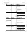
Features
Limit
Number of devices (IEC61850 equipment - Legacy
Bus equipment: C264, HMI, GTW, IED)
256
Binary inputs (SP, DP, SI, 1 among N)
5048/device
Measurements
512/ device
Counters
64/ device
Output controls
1024 /device
Setpoints outputs (binary and analogue)
512 /device
TABLEAU 1: GENERAL FEATURES
GTW/EN TD/C80
Technical Data
Page 4/14
PACiS GTW gateway
2.
INDUSTRIAL PC CHARACTERISTICS
2.1
Operating System
Gateway software is intended to run under an industrial PC running under Windows 2003
Server, Windows XP or Windows XP Embedded operating system with at least 256 Mo of
RAM.
Using 256 Mo of RAM you will not need a swap memory i.e. the gateway and the system will
run in RAM.
2.2
Configuration
The configuration of the gateway is given in table 1 of chapter GTW/EN HW. This
configuration complies with the environmental constraints given hereafter.
2.3
Communication ports with SCADA
•
Number of simultaneous protocols: 4
•
Number of serial ports by protocol: 2 (main, redundant)
•
Thus 8 ports maximum on one gateway: 2 cards with 4 ports
•
Number of communication ports: 8 at the most, set by PACiS SCE
•
Baud rate (bits/s): from 100 to 38400, set by PACiS SCE
The motherboard has 2 serial communication ports. You can use them for one
communication with SCADA plus a redundant port or 2 communications with SCADA. For
additional communication ports , add a PCI or an ISA communication card into the PC.
2.4
Ethernet Communication port
The Ethernet communication port is a 10 / 100 Mbps RJ45 connector.
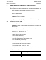
2.5
Rated Values
TEST
INTERNATIONAL
STANDARD
Harmonised
Rated Auxiliary Voltage IEC 60255-6
DC
Minimum requirement
Rated Frequency
IEC 60255-6
50 or 60 Hz.
Rated AC Voltage
No Standard
84 à 240 VAC
48 VDC, 110/125 VDC, 220/250 VDC
Technical Data
GTW/EN TD/C80
PACiS GTW gateway
2.6
Page 5/14
DC auxiliary supply
TEST
INTERNATIONAL
STANDARD
Harmonised
Supply variations
IEC 60255-6
Vn +/- 20%
Vn + 30% & Vn - 25% for information
Ramp down to zero
/
From Vn down to 0 within 1mn
From Vn down to 0 within 100mn
Ramp up from zero
/
From 0 up to Vn within 1mn
From 0 up to Vn within 100mn
Supply interruption
IEC 60255-11
From 2ms to 100ms at 0,88Vn
40s interruption
IEC 60255-11
/
Reverse polarity
/
Continuous withstand
Ripple (frequency
fluctuations)
IEC 60255-11
12% x Vn AC ripple, frequency = 100Hz
or 120Hz
12% x Vn AC ripple, frequency = 200Hz
for information
2.7
2.8
AC auxiliary supply
TEST
INTERNATIONAL
STANDARD
Harmonised
Supply variations
IEC 60255-6
Vn +/- 20%
Dips & Short
interruptions
IEC 61000-4-11
2ms to 20ms
Frequency fluctuations
IEC 60255-6
From 44 to 55Hz
Harmonics Immunity
IEC 61000-4-7
5% over the range 2nd to 17th
50ms to 1s
Insulation
TEST
INTERNATIONAL
STANDARD
Harmonised
Dielectric
IEC 60255-5: 2000
2KV, 50Hz, 1mn CM
IEEE C37.90.1: 1989
2KV, 50Hz, 1mn CM
1KV, 50Hz, 1mn DM
Insulation Resistance
IEC 60255-5: 2000
>100MΩ at 500VDC
HV Impulse
IEC 60255-5: 2000
Class 1:
5KV, 1.2/50μs, 0.5J, 500Ω CM on power
supplies
3KV, 1.2/50μs, 0.5J, 500Ω DM on power
supplies
Class 1:
1KV, 1.2/50μs, 0.5J, 500Ω CM on
communications
GTW/EN TD/C80
Technical Data
Page 6/14
2.9
PACiS GTW gateway
Environmental
TEST
INTERNATIONAL
STANDARD
Harmonised
Cold Operating
IEC 60068-2-1
Test Ad: -10°C, 96h
Cold Storage
IEC 60068-2-1
Test Ad: -40°C, 96h
Dry Heat Operating
IEC 60068-2-2
Test Bd:
+40°C, 96h, accurate +55°C, 2h, errors
acceptable
2.10
Dry Heat Storage
IEC 60068-2-2
Test Bd: +70°C, 96h
Damp Heat Operating
IEC 60068-2-3
Test Ca: +40°C, 10 days, 93% RH
IEC 60068-2-30
+25°C to +55°C, 93% RH, 3 cycles of
24h
Mechanical
INTERNATIONAL
STANDARD
Harmonised
Vibration response
(energised)
IEC 60255-21-1
Class 1
Vibration endurance
(non-energised)
IEC 60255-21-1
Class 1
Shock response
(energised)
IEC 60255-21-2
Class 1
Bump (non-energised)
IEC 60255-21-2
Class 1: 10g, 16ms, 2000/axis
Seismic (energised)
IEC 60255-21-3
Class 1
no packaging
IEC 60068-2-31
Test Ec: 2 drops from 50mm corner
drop, and topple test
with packaging
IEC 60068-2-32
Test Ed: 2 drops from 0.5m on each
face, edge and corner
TEST
Drop
2.11
Safety
TEST
Product Safety
INTERNATIONAL
STANDARD
CAPIEL draft Product
Safety document under
preparation
Harmonised
CE mark conformity
Technical Data
GTW/EN TD/C80
PACiS GTW gateway
2.12
Page 7/14
EMC TESTS
TEST
INTERNATIONAL
STANDARD
Harmonised
Electrostatic Discharge
IEC 61000-4-2
Cover on: Class III:
8KV air discharge
6KV contact discharge
RFI Immunity-radiated
IEC 61000-4-3
Class III:
10V/m, 80 to 1000MHz
Modulation: 1KHz, 80%
Polarisation H & V
ENV 50204
10V/m, 900 to 1800MHz
Modulation: 50%
Fast Transient Burst
IEC 61000-4-4
Class IV on power supply: 4KV, 2.5KHz
Class III on communications: 2KV, 5KHz
Surge Immunity
IEC 61000-4-5
Level 3 on power supply:
2KV CM / 1KV DM
Level 3 on communication:
2KV CM
Conducted RFI
Immunity
IEC 61000-4-6
10Vrms, 150KHz to 80MHz
Power Frequency
IEC 61000-4-8
Magnetic Field Immunity
30A/m continuous
Damped Oscillatory
IEC 61000-4-10
Magnetic Field Immunity
10A/m
High Frequency
Disturbance
Class III on power supply:
IEC 61000-4-12
2.5KV CM / 1KV DM
1MHz, 400 bursts/s & 100KHz,
50 bursts/s
Class II n communications:
1KV CM / 0,5KV DM
RFI Emissions
Conducted Emissions
IEC 60255-25
Class A: 0.15 to 30MHz:
0.15 to 0.5MHz: 79dBμV quasi peak
0.5 to 30MHz: 73dBμV quasi peak
Radiated Emissions
IEC 60255-25
Class A:
30 to 1000MHz: 30dBμV/m at 30m or
40dBμV/m at 10m
GTW/EN TD/C80
Page 8/14
2.13
Technical Data
PACiS GTW gateway
Wiring
The connection with the PACiS GTW gateway is full compatible with standard RS232C.
A SCADA communication can be establish on one serial port. One more serial port is
needed for redundancy.
A Null-Modem cable can be connected to a SCADA simulator or a Network Analyser.
For more information about the connection see the chapter CO.
Technical Data
GTW/EN TD/C80
PACiS GTW gateway
Page 9/14
3.
NON-ROTATING PART EMBEDDED PC CHARACTERISTICS
3.1
Operating system
Gateway software is intended to run under a dedicated non-rotating part Embedded PC with
the following characteristics:
3.2
•
Model: ADVANTECH UNO-3074 fanless Embedded Box Computer
•
Processor: M 1.4/1.8 GHz
•
Memory: 1 GB DDR SDRAM
•
24 V Power Supply.
•
OS Support Windows XP embedded
Configuration
The configuration of the gateway is given in chapter GTW/EN HW. This configuration
complies with the environmental constraints given hereafter.
3.3
Communication ports with SCADA
•
Clock Battery-backup RTC for time and date
•
LAN 2 x 10/100Base-T RJ-45 ports (Built-in boot ROM in flash BIOS)
•
Serial Ports 2 x RS-232, 2 x RS-232/422/485 with DB9 connectors Automatic RS-485
data flow control
•
Serial Port Speed RS-232: 50 bps ~ 115.2 kbps RS-422/485: 50 bps ~ 921.6 kbps
(Max.)
•
USB Ports 4 x USB, USB EHCI, Rev. 2.0 compliant
•
Digital Inputs (4-ch. wet contact DI0 ~ DI3)
- 2,000 VDC isolation
- 50 ~ 70 VDC over-voltage protection
- ±50 VDC input range and 10 kHz speed
- Interrupt handling speed: 10 kHz
•
Digital Outputs (4 ch. DO0 ~ DO3)
- 2,000 VDC isolation and 200 mA max/channel sink current
- Keep output status after system hot reset
- 0 ~ 40 VDC output range and 10 kHz speed
•
Counters/Timers (2 x 16-bit)
- Counter source: DI1 & DI3, Pulse output: DO2 & DO3
- Can be cascaded as one 32-bit counter/timer
- Down counting, preset counting value
- Timer time base: 100 kHz, 10 kHz, 1 kHz, 100 Hz
In the ADVANTECH PC configuration described below the PC has four serial communication
ports and 2 Ethernet communication ports. You can use them for one communication with
SCADA plus a redundant port or two communications with SCADA.
3.4
Mechanical
Construction
Aluminum housing
Mounting
Dimensions (W x H x D)
Wall/Panel/Stand
193 x 237 x 179 mm (7.6" x 9.3" x 7.0" for UNO-3074)
Weight
7 kg
GTW/EN TD/C80
Technical Data
Page 10/14
3.5
Power Supply
Output Rating
Input Voltage
3.6
PACiS GTW gateway
24 W (typical, no PCI cards)
9 ~ 36 VDC (e.g. +24 V @ 2 A) (Max. 5A),
AT. (16 ~ 36 VDC for 12 V PCI boards)
Environment Specifications
Operating Temperature
-20 ~ 55° C (-4 ~ 131° F) @ 5 ~ 85% RH (with CF card)
Relative Humidity
EMC Approved
95% @ 40° C (non-condensing)
IEC 68 2-64 (Random 1 Oct./min, 1hr/axis.)
CompactFlash: 2 Grms @ 5 ~ 500 Hz
HDD: 1 Grms @ 5 ~ 500 Hz
IEC 68 2-27
CompactFlash: 50 G @ wall mount, half sine, 11 ms
HDD: 20 G @ wall mount, half sine, 11ms
CE, FCC class A, UL, CCC
Safety Approved
UL
Vibration Loading
Shock During Operation
3.7
Wiring
3.7.1
Serial connection
The connection with the PACiS GTW gateway is full compatible with standard
RS 232/422/485 (Two RS-232 & two RS-232/422/485 ports with RS-485 automatic flow
control).
COM1 and COM2 are compatible with standard RS-232 serial communication interface
ports.
COM3 and COM4 are compatible with standard RS-232/422/485 serial communication
interface ports. The default setting for COM3 and COM4 is for RS422/485
A SCADA communication can be established on one serial port. One more serial port is
needed for redundancy.
A Null-Modem cable can be connected to a SCADA simulator or a Network Analyser.
For more information about the connection see the chapter CO.
3.7.2
Ethernet connection
The connection with the PACiS GTW gateway is full compatible with standard 10/100 Mbps
RJ45.
A SCADA communication can be establish on one Ethernet port. One more Ethernet port is
needed for redundancy.
A crossover Ethernet cable can be connected to a SCADA simulator or a Network Analyser.
For more information about the connection see the chapter CO.
Technical Data
GTW/EN TD/C80
PACiS GTW gateway
Page 11/14
4.
SOFTWARE GATEWAY CHARACTERISTICS
4.1
Number of Data Points
Refer to § 1.1.
4.2
Response time
Time to receive a response after sending a request: 100ms
4.3
SBUS Avalanche
The linked list that manage events can memorise 15 000 events by protocol process.
4.4
Exchanging message with SCADA
Response time to a SCADA request after the parameter settings phase for the parameters,
synchronisation pre and post transmission times:
less than 30 milliseconds regardless of the protocol
4.5
SBUS acquisition
The gateway can support avalanche of events without loss during a short period of time.
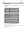
4.6
Time specifications
Operations
Gateway
Time between DI change of state at bay computer and
gateway reception
500 ms
Time between AI change of value at bay computer and
gateway reception
sampling period + 1 s
Time between gateway control initiation and DO activation 750 ms
TABLEAU 2: TIME SPECIFICATIONS
4.7
ISaGRAF 5.21
Function No.
Typical maximum values
Programs
160
Functions
100
Function blocks
300
Variables
5000 (all except datapoints)
Datapoints
3000
Simultaneous resources on non redundant GTW-Isa
8
Simultaneous resources on redundant GTW-Isa
8
Resource cycle time nominal: 100 ms
TD/HW/MF
GTW/EN TD/C80
Technical Data
Page 12/14
PACiS GTW gateway
5.
GI74 CHARACTERITICS
5.1
Operating System
The GI74 software is intended to run under the below described industrial PC only running
under VxWorks with a specific communication board (BCOM8+).
5.2
Configuration
The industrial PC where the GI74 is running has the following configuration
Reference
Designation
2070368A07
GI74 Supply 48VDC and filter
2070368A08
GI74 Supply 110VDC and filter
2070368A09
GI74 Supply 220VAC and filter
9565913
Serial board BCOM8 (from ASE)
INDUSTRIAL PC base version
Rack Schneider Electric GI74
CPU TEKNOR PCI 946/P3-700
Memory 128 Mo PC100 SDRAM
FDP PICMG PCI-7S version G1
Flash disk IDE 16 Mo
Cable Flash disk + adapter
Floppy driver 3,5”
Cable Floppy
Board reprise unpopulated
Cable LED
Cables COM1/COM2
TABLEAU 3: GI74 CONFIGURATION
5.3
Communication ports with SCADA
A dedicated communication card assumes communication with SCADA: BCOM8+.
This card can manage up to four communication ports.
Baud rates: 300 to 2400
Technical Data
GTW/EN TD/C80
PACiS GTW gateway
Page 13/14
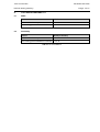
6.
SYSTEM DEPENDABILITY
6.1
MTBF
Device
MTBF
Industrial PC Gateway
50 000h
Non rotating part embedded PC Gateway 72 000h
TABLEAU 4: MTBF
6.2
Availability
Device
MTTR (in minutes)
Industrial PC Gateway
30 to 60
Non rotating part embedded PC Gateway 14 to 16
TABLEAU 5: AVAILABILITY
GTW/EN TD/C80
Technical Data
Page 14/14
PACiS GTW gateway
BLANK PAGE
Introduction
GTW/EN IT/C80
PACiS GTW Gateway
INTRODUCTION
Introduction
PACiS GTW Gateway
GTW/EN IT/C80
Page 1/8
CONTENT
1.
INTRODUCTION
3
2.
INTRODUCTION TO PACiS GTW GATEWAYS' GUIDES
4
2.1
Chapters description
4
2.1.1
Safety Chapter (SA)
4
2.1.2
Introduction Chapter (IT)
4
2.1.3
Functional Description Chapter (FT)
4
2.1.4
Technical Data Chapter (TD)
4
2.1.5
Communications Chapter (CT)
4
2.1.6
HMI, Local control and user interface Chapter (HI)
4
2.1.7
Installation Chapter (IN)
4
2.1.8
Hardware Description Chapter (HW)
4
2.1.9
Connection diagrams Chapter (CO)
4
2.1.10
Commissioning Chapter (CM)
4
2.1.11
Record Sheet Chapter (RS)
5
2.1.12
Applications Chapter (AP)
5
2.1.13
Maintenance, Fault finding, Repairs Chapter (MF)
5
2.1.14
Lexicon Chapter (LX)
5
2.1.15
Problem Analysis Chapter (PR)
5
2.1.16
Logic Diagrams Chapter (LG)
5
2.2
Operation guide
5
2.3
Technical guide
5
2.4
Extra information
5
3.
INTRODUCTION TO PACiS
6
3.1
What are PACiS Products?
6
3.2
Application and Scope
6
3.3
Gateway environment
7
GTW/EN IT/C80
Introduction
Page 2/8
PACiS GTW Gateway
BLANK PAGE
Introduction
PACiS GTW Gateway
1.
GTW/EN IT/C80
Page 3/8
INTRODUCTION
The present document is a chapter of the PACiS GTW Gateway documentation. It describes
the documentation’s chapters you can find in the different guides, the types of applications
and how to use the product. It is the Introduction (IT) chapter of this Product's manual.
GTW/EN IT/C80
Page 4/8
2.
Introduction
PACiS GTW Gateway
INTRODUCTION TO PACiS GTW GATEWAYS' GUIDES
This version of the PACiS GTW documentation refers to version PACiS V4.8. The guides
provide functional and technical descriptions of the product and of a comprehensive set of
functions for the product’s use and applications.
PACiS GTW Gateways guides are divided into two volumes, as follows:
•
Operation Guide: includes information on the application of the product and a
technical description of its features. It is mostly intended for engineers involved in the
selection and application of the product.
•
Technical Guide: contains information on the installation and commissioning of the
product, and also a fault finding section. This volume is intended for site engineers
who are responsible for the installation and commissioning of the product.
2.1
Chapters description
2.1.1
Safety Chapter (SA)
This chapter contains the safety instructions, handling and reception of electronic equipment,
packing and unpacking of parts, Copyrights and Trademarks.
2.1.2
Introduction Chapter (IT)
This is the present document, it contains the description of each chapter of the PACiS GTW
Gateway guides. It presents a brief introduction to PACiS GTW Gateways capabilities.
2.1.3
Functional Description Chapter (FT)
This chapter contains a description of the product. It describes the functions of the PACiS
GTW Gateway.
2.1.4
Technical Data Chapter (TD)
This chapter contains technical data, including accuracy limits, recommended operating
conditions, ratings and performance data. It also lists environment specification, compliance
with technical standards.
2.1.5
Communications Chapter (CT)
This chapter provides detailed information on the communication interfaces of the product,
i.e. it gives the profiles of the implemented protocols.
2.1.6
HMI, Local control and user interface Chapter (HI)
This chapter contains the operator interface description, Menu tree organisation and
browsing, description of LEDs and Setting/configuration software.
2.1.7
Installation Chapter (IN)
This chapter contains the installation procedures.
2.1.8
Hardware Description Chapter (HW)
This chapter contains the hardware product description.
2.1.9
Connection diagrams Chapter (CO)
This chapter contains the external wiring connections.
2.1.10
Commissioning Chapter (CM)
This chapter contains instructions on how to commission the product, including setting and
functionality checks of the product.
Introduction
PACiS GTW Gateway
2.1.11
GTW/EN IT/C80
Page 5/8
Record Sheet Chapter (RS)
This chapter contains record sheet to follow the maintenance of the PACiS GTW Gateway
product.
2.1.12
Applications Chapter (AP)
This chapter gives a comprehensive and detailed description of the features of the PACiS
GTW Gateways product. This chapter includes a description of common system applications
of the PACiS GTW Gateway, practical examples on how to perform certain basic functions,
suitable settings, a few typical worked examples and information on how to apply the
settings to the product.
2.1.13
Maintenance, Fault finding, Repairs Chapter (MF)
This chapter advises on how to recognise failure modes, fault codes and describes the
recommended actions for repair.
2.1.14
Lexicon Chapter (LX)
This chapter contains lexical description of acronyms and definitions.
2.1.15
Problem Analysis Chapter (PR)
This chapter contains identification and resolution of the main problems which can occurs on
the PACiS GTW Gateway.
2.1.16
Logic Diagrams Chapter (LG)
This chapter contains logic diagrams of the PACiS GTW Gateway.
2.2
Operation guide
This binder contains the following chapters: SA, TD, IT, HW, AP, FT, LX.
2.3
Technical guide
This binder contains the following chapters: SA, TD, IT, HW, CO, IN, HI, CT, CM, RS, , PR,
FT, LG, LX.
2.4
Extra information
Ask for Chapter MF.
GTW/EN IT/C80
Page 6/8
3.
Introduction
PACiS GTW Gateway
INTRODUCTION TO PACiS
Schneider Electric philosophy is to provide a full range of products, computers, gateways
and IEDs products. Each of these products can be used independently, or can be integrated
to form a PACiS system: a Digital Control System (DCS) SCADA system.
3.1
What are PACiS Products?
Driven by worldwide requirements for advanced applications in SCADA, Digital Control
Systems, Automation, control and monitoring, Schneider Electric have designed and
developed a new and comprehensive system: PACiS, specifically intended for the power
process environment and electrical utility industry. It allows building of a customised solution
for Control, Monitoring, Measurement and Automation of electrical processes.
This new generation of products has been specially tailored for the PACiS system. A major
objective for PACiS products is to make this range as easy as possible for the customer to
accept, adapt and integrate into their system and operation.
One of the key features is that this product family is based on a IEC61850 client/server
architecture.
3.2
Application and Scope
The Telecontrol Gateway (GTW) is the PACiS control system's gateway. It provides the
system with a connection to a Remote Control Point (RCP), located in a dispatching centre
(SCADA), thus allowing the dispatcher to perform remote control and monitoring of the
system from the SCADA.
Main functions of the gateway are:
•
Transmission of remote indications from the system to the control centre.
•
Transmission of remote measurements from the system to the control centre.
•
Transmission of commands to the system, issued from the remote control centre.
GTW and RCP communicate together by data exchanges based on a specific
communication protocol. The TGW label describes in fact a range of bridges, each
supporting a protocol dedicated to a specific remote control type.
The communication with the SCADA uses a RS232 or Ethernet links.
The TG may be redundant in the PACiS system in order to ensure the quality of service in
case of a communication failure. Moreover, it should be multi-protocol, this means it has to
manage several different protocols in order to communicate with several different SCADAs.
A standardised protocol is used in accordance with the choice of each project's SCADA
supplier.
Introduction
GTW/EN IT/C80
PACiS GTW Gateway
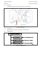
3.3
Page 7/8
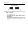
Gateway environment
The PACiS GTW Gateway is a dedicated device (PC TYPE): do not confuse it with the
remote control interface function which may be included in the MiCOM C264 computers.
FIGURE 1: PACiS GTW GATEWAY ENVIRONMENT
GTW/EN IT/C80
Introduction
Page 8/8
PACiS GTW Gateway
BLANK PAGE
Hardware Description
GTW/EN HW/C80
PACiS GTW gateway
HARDWARE DESCRIPTION
Hardware Description
GTW/EN HW/C80
PACiS GTW gateway
Page 1/8
CONTENT
1.
INTRODUCTION
3
2.
INDUSTRIAL PC DESCRIPTION
4
2.1
Main features
4
2.2
Description
5
2.2.1
Dimensions
5
2.2.2
Front panel
5
2.2.3
Rear panel
6
2.2.4
Power supply
6
2.3
Communication
6
3.
NON-ROTATING PART EMBEDDED PC MiCOM A300 DESCRIPTION
7
3.1
Main features
7
3.2
Front and rear view dimentions for MiCOM A300 Panel External I/O
8
3.3
Rear Panel External I/O for MiCOM A300
8
GTW/EN HW/C80
Hardware Description
Page 2/8
PACiS GTW gateway
BLANK PAGE
Hardware Description
GTW/EN HW/C80
PACiS GTW gateway
1.
Page 3/8
INTRODUCTION
This document is a chapter of the PACiS GTW gateway documentation. It is the chapter
Hardware Description (HW) of this Product.
The gateway may be either an industrial PC or a Non-rotating part Embedded PC.
To get further details about the PC hardware, refer to the User’s Manual supplied with the
industrial PC or with the Non-rotating part Embedded PC.
GTW/EN HW/C80
Hardware Description
Page 4/8
PACiS GTW gateway
2.
INDUSTRIAL PC DESCRIPTION
2.1
Main features
To increase environmental capabilities, an industrial PC may be used. It is a steel rugged
chassis specially designed to work under harsh environment for high reliability application.
The hardware description of this PC configuration is done hereafter.
This PC is equipped with the following modules:
Reference
Designation
9566085B3 Chassis
Power Supply
4U Rackmount Mother Board Chassis (Black)
400W A TX/PFC Auto-Switching Power Supply
Floppy Disk Reader 3.5" 1.44 MB Floppy Disk Drive (Black)
DVD
DVD R/W Drive: 20X IDE DVD+/-RW Drive (Black)
Fan Filter
Fan Filter
Door Filter
Door Filter
Cooler
LGA775 CPU cooler
Mother Board
LGA775 CoreTM2 Duo/Pentium® 4 Industrial ATX MB
FSB 1066 MHz with Single Gigabit LAN
Processor
Intel® CoreTM2 Duo E6700 processor LGA775 2.66
Ghz/4MB L2 cache 1066 MHz/FSB
MEMORY DDR2
Dual Channel DDR2-667 MHz 4 GB (4 x 1 GB)
non-ECC non-Register 240-Pin
Hard disk
HDD: 2xSerial-ATA 3.5", SEAGATE, 160 GB, 7200 RPM
RAID
RAID Card: PROMISE RAID 5 CARD SATA 24 CH PCI
(G) - SATA II RAID Controller card, with 2-SATA ports,
128 MB DDR2 533 RAM, PCIex4
LAN/NIC
Additional NIC Card: Dlink / Intel Network Card
10/100/1000 M PCI Slot
Keyboard
Microsoft® USB 104 Key Keyboard (Black)
Mouse
Microsoft® 3-Button USB Optical Mouse (Black)
Operating System
Microsoft® Windows XP Professional SP3 OEM
Test
IPC System Installation and 8-hour burn-in-test included
TABLEAU 1: INDUSTRIAL PC SPECIFICATION
Hardware Description
GTW/EN HW/C80
PACiS GTW gateway
2.2
Description
2.2.1
Dimensions
Page 5/8
431mm x 413.5mm x 176mm
FIGURE 1: INDUSTRIAL PC DIMENSIONS
2.2.2
Front panel
RESET SWITCH
FILTER COVER
KEYLOCK
POWER SWITCH
EXT. KEYBOARD
POWER LED
HD-LED2
HD-LED1
S0134ENa
FIGURE 2: FRONT PANEL
•
EXT. KEYBOARD: external keyboard is optional.
•
HD LED 1and 2: indicate that the hard disk is being accessed.
•
POWER LED: this led is green to indicate when the PC is powered on.
•
POWER SWITCH: monostable button of the 3.3 VDC ATX power supply.. The first
push powers on the PC; the second one turns it off..
•
RESET SWITCH: this button is here to reset the PC.
•
FILTER COVER: see the user’s manual to know how to replace the filter cover.
GTW/EN HW/C80
Hardware Description
Page 6/8
2.2.3
PACiS GTW gateway
Rear panel
You will need to take care of keeping some place for wiring connections.
Video card
Ethernet board
USB Mouse
CPU extension
Serial DB 9
connector
14 ISA/PCI slots
Power
Keyboard
connection
PS2 Mouse
RJ 45 Station Bus
connection
Remote SCADA
connection (4 ports)
FIGURE 3: REAR PANEL
2.2.4
Power supply
The industrial PC is powered by 115V/230VAC with auto-switching.
2.3
Communication
FIGURE 4: COMMUNICATION
S0135ENa
Hardware Description
GTW/EN HW/C80
PACiS GTW gateway
3.
Page 7/8
NON-ROTATING PART EMBEDDED PC MiCOM A300 DESCRIPTION
Advantech's UNO-3074 series is high-performance Pentium M/Celeron M grade, embedded
automation computers with four PCI expansions.
UNO-3074 features a rugged and field-proven design offering dual power inputs and battery
backup SRAM.
Different from general industrial PCs, UNO-3074 is more compact and reliable.
This is an open platform which can fulfill any demanding requirement from the industrial field,
and it is an ideal solution for industrial automation and control.
UNO-3074 provides embedded operating system with a pre-configured image that has
optimized onboard device drivers, and support Windows XP Embedded to fulfill the toughest
requirements for complete functionality and high reliability.
Note:
3.1
The product specification is detailed in the TD (Technical Data)
chapter.
Main features
•
Supplier: Advantech
•
Reference model: UNO-3072/3074
•
Onboard Pentium® M processor
•
Onboard 512 KB battery-backup SRAM
•
Two RS-232 & two RS-232/422/485 ports with RS-485 automatic flow control
•
Four USB 2.0 ports
•
Additional NIC Card: Dlink / Intel Network Card 10/100/1000 M PCI Slot
•
Two/ Four PCI-bus expansion slots for versatile applications
•
Industrial proven design; anti-shock up to 50 G, anti-vibration up to 2 G, Flash memory
in place of hard disk
•
4-ch isolated DI, 4-ch isolated DO with timer, counter and interrupt handling
•
Supports dual power inputs
•
Windows® 2000/XP and Embedded Linux support
•
Windows XP (SP2) Embedded ready platforms with write protection (EWF)
•
Onboard system & I/O LED indicators
•
Supports Boot from LAN function
•
Fanless design with no internal cabling.
•
Reset button
•
VGA display connector
•
RTX 2009 Runtime for ISaGRAF automation: Real-Time eXtension for Win32
platforms, by Interval Zero.
GTW/EN HW/C80
Hardware Description
Page 8/8
3.2
PACiS GTW gateway
Front and rear view dimentions for MiCOM A300 Panel External I/O
FIGURE 5: MiCOM A300 INDUSTRIAL PC DIMENSIONS
3.3
Rear Panel External I/O for MiCOM A300
FIGURE 6: MiCOM A300 REAR PANEL
Application
GTW/EN AP/C80
PACiS GTW gateway
APPLICATION
Application
PACiS GTW gateway
GTW/EN AP/C80
Page 1/84
CONTENT
1.
SCOPE OF THE DOCUMENT
3
2.
REQUIREMENTS
4
3.
PACiS GATEWAY CONFIGURATION SCOPE
5
3.1
General PACiS system configuration
5
3.2
GTW configuration in general PACiS system configuration
5
3.3
Sparing object
6
4.
DEFINING PACiS GATEWAY CONFIGURATION IN
SYSTEM ARCHITECTURE
7
4.1
Adding a GTW in the system architecture
7
4.2
Setting specific parameterisation of GTW
8
4.2.1
Locating GTW in a substation (mandatory)
9
4.2.2
Configuring a communication channel
9
4.3
Networking GTW on the station-bus network
11
4.3.1
Connecting GTW to others station-bus sub-systems
11
4.3.2
Defining addressing mapping of station-bus network
12
4.3.3
Addressing datapoint on station-bus network
13
4.4
Networking SCADA on GTW SCADA network
13
4.4.1
Creating a SCADA network
13
4.4.2
Defining addressing mapping of SCADA legacy network
28
4.4.3
Addressing datapoint on SCADA legacy network
55
4.5
Setting system information for GTW components
56
4.5.1
Setting general system information of GTW
57
4.5.2
Setting system information of SCADA network
58
4.6
Gateway legacy networks
60
4.6.1
Creating a Gateway legacy networks
60
4.6.2
Setting specific attributes of a MODBUS IED network
60
4.7
Defining a PLC
63
5.
DEFINING PACiS GATEWAY CONFIGURATION IN
ELECTRICAL ARCHITECTURE
64
5.1
Defining Substation and Bay Local/Remote dependencies
64
5.1.1
Introduction
64
5.1.2
Setting ‘Local/remote dependencies’ attributes of control datapoint
65
5.2
Setting SBMC dependency attribute of control datapoint
66
5.2.1
Introduction
66
5.2.2
Setting ‘SBMC dependency’ attribute of control point
66
GTW/EN AP/C80
Page 2/84
Application
PACiS GTW gateway
5.3
Defining Taking Control for substation and SCADA links
67
5.4
Defining an ISaGRAF RT automation
69
5.4.1
Creating an ISaGRAF RT automation (header definition)
70
5.4.2
Adding specific datapoints to RT automation (interface definition)
71
5.4.3
Creating ISaGRAF client link (interface definition)
72
5.4.4
Creating ISaGRAF server link (interface definition)
73
5.4.5
Using ISaGRAF editor (body definition)
74
6.
DEFINING IEC61850/IEC61850 PACiS GATEWAY CONFIGURATION
76
6.1
Configuring the GTW in the lower network
77
6.2
Configuring the GTW in the upper network
79
7.
DEFINING PACiS GATEWAY INITIALIZATION TIMER
83
Application
PACiS GTW gateway
1.
GTW/EN AP/C80
Page 3/84
SCOPE OF THE DOCUMENT
The present document is a PACiS Gateway (GTW) chapter of the documentation binder.
This document is intended to present you how to configure the GTW. It is the chapter
Application (AP) of this Product.
GTW/EN AP/C80
Page 4/84
2.
Application
PACiS GTW gateway
REQUIREMENTS
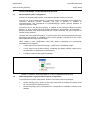
First, if it is not already done, you will need to install the PACiS SCE (System Configuration
Editor), see the chapter IN (Installation) of this product.
This document presents you the objects and the attributes of a referenced database made
with the PACiS SCE. For understanding this document you first need to be familiar with
PACiS SCE.
Moreover, this document reduces PACiS Gateway (GTW) configuration to GTW
functionality, that are datapoint real-time values and controls transmitted for SCADA. These
datapoints are globally produced and managed by others PACiS sub-systems mainly
MiCOM C264 computers. So, the configurations of datapoint and by extension of the
substation electrical topology where datapoints are attached are pre-requirements to GTW
configuration. They are not described is the present document, but in the MiCOM
C264/C264C application chapter (C264/EN AP). Nevertheless, some items of datapoint and
electrical topology configuration can be repeated and reformalised in the present document
as far as GTW functionality are concerned by.
To add a PACiS GTW into an existing system you need to have the mapping of the system
(IP address, Network names of equipment…).
To generate a template, for an existing GTW, see the chapter of the PACiS SCE product.
Application
GTW/EN AP/C80
PACiS GTW gateway
3.
PACiS GATEWAY CONFIGURATION SCOPE
3.1
General PACiS system configuration
Page 5/84
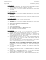
To define a complete PACiS system, three aspects should be taken into account.
The first one is the system topology. It consists of device composition that manages the
customer’s electrical process. Generally, this part of furniture is relevant to
Schneider Electric and corresponds to Schneider Electric system process definition to
respond customer’s needs.
The second one is the electrical topology. It consists of the customer’s electrical process
definition in term of typed electrical devices (transformer, disconnector, circuit-breaker…)
that are connected each other through busbars or lines. Generally, this part of furniture is
relevant to the customer.
The third one is the graphical topology. It consists of the mimic and their graphical animation
descriptions that appear at substation control points (operator interface) and bay control
points (MiCOM C264 computer local HMI).
When creating a new configuration using SCE, these 3 topologies are automatically
instantiated via root objects:
•
A ‘Site’ object for the electrical topology, containing one ‘Substation’ object
•
A ‘Scs’ object for the system topology, containing one ‘Station network’ object (Scs is
an abbreviation of Substation Control System)
•
A ‘Graphic’ object for the graphical topology.
FIGURE 1: GENERAL ARCHITECTURE OF A PACiS CONFIGURATION IN SCE
3.2
GTW configuration in general PACiS system configuration
In general PACiS system configuration, GTW is concerned by the two topologies:
•
System topology (Scs): GTW is a direct sub-component of the Ethernet network used
for communication at station bus level.
•
Electrical topology (Site): GTW behaviour is dependent of substation and bay mode
facilities.
GTW/EN AP/C80
Application
Page 6/84
3.3
PACiS GTW gateway
Sparing object
At SCE level, a spare object is an object having its spare attribute set to true. The
configuration of this object and of its spare attribute is the same as for any other object and
attribute. Any object can be spare and particularly those concerning MiCOM C264 computer
configuration.
Spare objects are not provided to the generator tools, respecting the following rules:
•
An object O2, not spare, linked directly or not to a spare composite parent object O1,
is considered as spare.
O1 (Spare = Yes)
O2 (Spare = No)
S0387ENa
•
A relation defined on an object O1, not spare, and linked to a spare object O2, is
considered as a relation without link.
O1 (Spare = No)
Relation
link
O2 (Spare = Yes)
S0388ENa
Application
GTW/EN AP/C80
PACiS GTW gateway
Page 7/84
4.
DEFINING
PACiS
ARCHITECTURE
GATEWAY
4.1
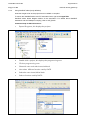
Adding a GTW in the system architecture
CONFIGURATION
IN
SYSTEM
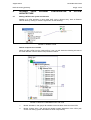
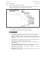
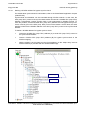
Addition of a GTW definition is done under SCE via the “Objects entry” area at Ethernet
network level by clicking on mouse’s right button as the following:
FIGURE 2: ADDING A GTW
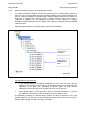
Default components of a GTW
When you add a GTW from the “Objects Entry” view, you will obtain the following sub-tree of
the GTW definition with the default components as follows:
FIGURE 3: DEFAULT COMPONENTS OF THE GTW
1.
Binder ‘Hardware’, that groups all available communication channels of the GTW.
2.
Binder ‘System infos’, that groups all general system datapoints of the GTW (see
section 4.5 Setting system information for GTW components)
GTW/EN AP/C80
Application
Page 8/84
4.2
PACiS GTW gateway
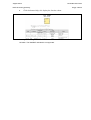
Setting specific parameterisation of GTW
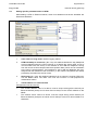
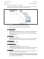
When adding a GTW on Ethernet network, some of its attributes must be set. Hereafter are
listed these attributes.
FIGURE 4: SETTING GENERAL ATTRIBUTES OF A GTW
1.
short name and long name: used for logging, alarms, …
2.
GTW timestamp at connection ( No / Yes): this attribute defines the way datapoints
are time-stamped when the GTW connects to a Station Bus server (after a loss of
communication with this server). If this attribute is set to No the datapoints coming
from this server are time-stamped with the acquisition date ( which can be antecedent
to the loss of communication). If this attribute is set to Yes the datapoints are timestamped with the date/time of the connection ( in this case the acquisition time-stamp
provided by the station bus server is lost).
3.
GI74 usage (No / Yes): this attribute indicates if GI 74 protocol is used at GTW level.
Use the default value. The value ‘Yes’ must not be used. It is still proposed for
maintenance reason.
4.
TCP/IP address and network name
Configuration rules and checks
•
The "TCP/IP address" value of a device, must be unique among all the devices per
Ethernet Network (except for OI server and OI client).It is the TCP/IP address on the
SBUS.
•
The "network name" value of a device, must be unique among all the devices per
Ethernet Network (except for OI server and OI client).It is the PC’s name limited to 15
characters.
Application
GTW/EN AP/C80
PACiS GTW gateway
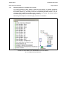
4.2.1
Page 9/84
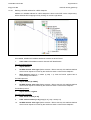
Locating GTW in a substation (mandatory)
Each system device has to be located in a specific substation. This is done by entering the
mandatory relation (1) “is located in:“ for each system device, especially GTWs.
FIGURE 5: LOCATING GTW IN A SUBSTATION
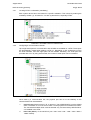
4.2.2
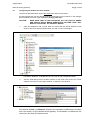
Configuring a communication channel
Up to eight serial ports for communication with SCADA are available on a GTW. These ports
are automatically created when adding a GTW (1). Depending on PC architecture running
the GTW software, less than eight ports can be useable. Generally, two serial ports are
provided with a PC. By using extra boards, the number of serial ports can be increased.
FIGURE 6: GTW COMMUNICATION CHANNEL
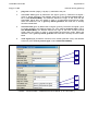
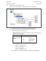
Once used by a communication link, the physical port has to be set relatively to the
communication link characteristics:
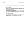
1.
protocol type (Usual protocol / GI 74 protocol / V35 ACKSYS-MCX): use the default
value. The value ‘GI 74’ must not be used. It is still proposed for maintenance reason.
The V35 ACKSYS-MCX value must be selected only if a board Acksys MCXPCI/5702 is installed in the GTW.
2.
baud rate (bits/s): of the serial link (100 / 200 / 300 / 600 / 1200 / 4800 / 9600 /
19200 / 38400).
GTW/EN AP/C80
Page 10/84
Application
PACiS GTW gateway
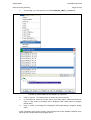
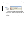
3.
plug com. number (range [1,16],step 1): attached to the port.
4.
transmitted clock (given by RXClockIn ext signal / given by TXClockIn ext signal /
given by bauds generator): this attribute exists only if the attribute protocol type is
set to V35 ACKSYS-MCX): this attribute defines the origin of the clock for the
transmitted signal when the board is used in synchronised asynchronous mode.
When this attribute is set to given by bauds generator the baud rate is actually
forced to 64000 bits/s.
5.
received clock (given by RXClockIn ext signal / given by TXClockIn ext signal / given
by bauds generator) this attribute exists only if the attribute protocol type is set to
V35 ACKSYS-MCX): this attribute defines the origin of the clock for the received
signal when the board is used in synchronised asynchronous mode. When this
attribute is set to given by bauds generator the baud rate is actually forced to 64000
bits/s.
6.
clock signal (high permanent / transmit clock / bauds generator clock): this attribute
exists only if the attribute protocol type is set to V35 ACKSYS-MCX)
(1)
(2)
(3)
(4)
(5)
(6)
FIGURE 7: CONFIGURING A COMMUNICATION CHANNEL (E.G. FOR PORT 1)
Application
PACiS GTW gateway
4.3
GTW/EN AP/C80
Page 11/84
Networking GTW on the station-bus network
GTW connection to the station-bus is implicitly done by adding the GTW hierarchically to the
Ethernet network (see section 4.1 Adding a GTW in the system architecture) and by setting
its IP characteristics (see 4.2 Setting specific parameterisation).
4.3.1
Connecting GTW to others station-bus sub-systems
To transmit information between PACiS sub-systems, IEC61850 protocol is used.
The data modelling of IEC 61850 protocol is based on a client-server architecture. Each IEC
61850 communicant PACiS sub-system (PACiS OI server, MiCOM C264 computer, and
PACiS GTW) owns an IEC 61850 mapping of data which it is server of. A PACiS sub-system
is server of a datapoint if it manages it, that is to say it produces its real-time value (in case
of input datapoint such as status, measurement, counter) or executes its real-time controls
(in case of output datapoint such as binary controls and setpoints).
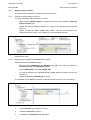
To connect a GTW (A) to a specific IEC 61850 communicant sub-system (B) on the stationbus, an extra relation ‘has for IEC 61850 server’ must be created for (A) and point to (B).
That means GTW (A) is client of sub-system (B) and can access to data managed by the
sub-system (B), i.e. read relevant real-time values from (B) and send real-time controls to
(B).
FIGURE 8: CONNECTING GTW TO OTHERS STATION-BUS SUB-SYSTEMS
When adding the ‘has for IEC61850 server’ relation to GTW (A), the specific attribute of the
relation, modelling/goose usage (1), is not significant: use its default value (Data model
only).
GTW/EN AP/C80
Page 12/84
Application
PACiS GTW gateway
FIGURE 9: GTW (A) AS IEC61850 CLIENT OF MiCOM C264 COMPUTER (B)
4.3.2
Defining addressing mapping of station-bus network
An IEC 61850 mapping is an aggregation of logical devices, composed of bricks. Generally,
a brick corresponds to an electrical device or function. It provides its real-time data (status,
measurements, and controls …) and some configuration aspects. To do that, a brick groups
data by categories (Status, measurement, Control, Configuration), called functional
components.
A functional component groups data objects. A data object must be seen as a real-time
equivalent of a PACiS datapoint. So, when a PACiS sub-system (IEC 61850 client) needs
the real-time value of a datapoint manages by another sub-system (IEC 61850 server), this
last one transmits the information via a data object of its own IEC 61850 mapping. At SCE
data modelling level, IEC61850 clients must precise which IEC61850 servers it retrieves
information from (see section 4.3.1 Connecting GTW to others station-bus sub-systems).
Generally, an IEC 61850 data object has a stereotype, called common class. The structures
of these ones are known by all PACiS IEC 61850 communicant sub-systems. For PACiS
sub-systems, the number and structure of common classes are fixed. They are the terminal
description of IEC61850 PACiS data modelling.
In IEC 61850 Mapping of PACiS sub-system, there is a native logical device LD0 with fixed
and hard-coded bricks (DBID, DI (LPHD), GLOBE (LLN0), and DIAG). When creating a
PACiS GTW at SCE level, an IEC 61650 mapping with LD0 and its default bricks is also
created. LD0 is a system logical device that groups all system diagnostics and controls
relevant to the GTW. Datapoints addressed in the brick of LD0 are only relevant to system
topology.
Extra logical devices can not be created in the IEC 61850 mapping of a GTW. Their usages
are reserved for MICOM C264 computer configuration.
Application
GTW/EN AP/C80
PACiS GTW gateway
Page 13/84
Overview of GTW IEC 61850 mapping’s LD0
The LD0 of PACiS GTW is fixed and composed of the following bricks:
•
DBID (DataBase IDentity) used for MiCOM C264 computer databases identification
and management,
•
DI (Device IDentity)/LPHD used for MiCOM C264 computer identification,
•
GLOBE/LLN0 used for MiCOM C264 computer mode management
•
TGDIAG brick, grouping statuses relevant to SCADA links managed by the GTW
FIGURE 10: STANDARD LD0 EXTENSION FOR GTW (SCE)
4.3.3
Addressing datapoint on station-bus network
For details refer to the C264/C264C application chapter (C264/EN AP).
4.4
Networking SCADA on GTW SCADA network
4.4.1
Creating a SCADA network
An electrical substation can be supervised and controlled from many points inside the
substation via PACiS operator interfaces (Substation Control Point or SCP) and/or PACiS
MiCOM C264 computer bay panels (Bay Control Point or BCP), and outside the substation.
Generally, the distant control of the substation (Remote Control Point or RCP) is done via
specific networks called SCADA legacy networks.
Several SCADA legacy networks can be connected to a PACiS system, via PACiS MiCOM
C264 computer or PACiS GTW sub-systems. SCADA legacy networks are managed as
master by distant SCADA and can be redundant for safety reason. A PACiS GTW can
manage up to four SCADA networks.
At SCE data modelling level, only SCADA legacy networks and their protocol are modelled
and connected to GTW sub-systems. Each SCADA network has to be linked to a main
communication port and eventually an auxiliary communication port in case of redundancy.
GTW/EN AP/C80
Application
Page 14/84
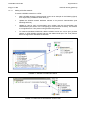
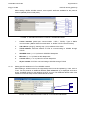
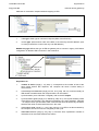
4.4.1.1
PACiS GTW gateway
Adding a SCADA network
To create a SCADA network on a GTW:
•
Add a SCADA network ("Usual protocol" given as an example in the following figure)
from object entry available at GTW level (1),
•
Update the SCADA network attributes relevant to its protocol characteristics (see
following sections),
•
Update its ‘has for main communication port’ relation and the communication port
characteristics (see section 4.2.2 Configuring a communication channel). This relation
is not significant for T104 protocol using an Ethernet protocol.
•
To create a redundant SCADA link, add the relation ‘has for aux. comm. port’ (2) extra
relation on GTW SCADA network and type the related serial port. The T104 protocol
does not support the redundant SCADA link.
FIGURE 11: ADDING A SCADA NETWORK
FIGURE 12: CREATING A REDUNDANT SCADA LINK
Application
GTW/EN AP/C80
PACiS GTW gateway
4.4.1.2
Page 15/84
Setting general attributes of a SCADA network
Whatever the kind of SCADA network, its short name and long name attributes (1) must be
updated for correct logging and alarm discrimination concerning status datapoints managed
by the GTW for each connected SCADA network as shown in figure 13.
FIGURE 13: SETTING GENERAL ATTRIBUTES OF A SCADA NETWORK
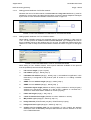
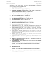
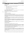
4.4.1.3
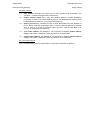
Setting specific attributes of a T101 SCADA network
When adding a SCADA network, the supported protocol must be updated (1). Here, set it to
‘T101’. For this protocol an additional attribute 'time reference' (2) is displayed and has to
be set. Available values for this attribute are UTC or local. This attributes defines which time
reference is used to stamp events transmitted to SCADA as shown in figure 14 and figure
15.
FIGURE 14: SETTING PROTOCOL TYPE OF A SCADA NETWORK
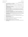
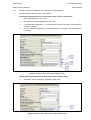
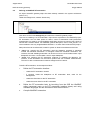
When setting a T101 SCADA network, some specific attributes available for the protocol
must be updated (Protocol and SOE tab-panes):
1.
link address length (1 byte / 2 bytes)
2.
link address (range [1, 65534], step 1)
3.
redundant link address (range [1, 65534], step 1): this attribute is significant if a line
redundancy is configured for the protocol (refer to section 4.4.1.1 Adding a SCADA
network).
4.
ASDU common address length (range [1, 65534], step 1)
5.
ASDU common address (range [1, 65534], step 1)
6.
information object length (Address on 8 bits (1 byte) / Address on 16 bits (2 bytes) /
Address on 8 bits.8 bits / Address on 8 bits.16 bits / Address on 16 bits.8 bits /
Address on 8 bits.8 bits.8 Bits / Address on 24 bits (3 bytes))
7.
frame max length (range [1, 255], step 1)
8.
cause of transmission length (Address on 8 bits / Address on 16 bits)
9.
MV periodic cycle (range [0 s, 65534 s], step 1 s)
10.
binary time size (CP24Time2A (3 bytes) / CP56Time2A (7 bytes))
11.
background scan cycle (range [0 s, 65535 s], step 1 s)
12.
quality value for toggling xPS ( BL only (blocked) / IV only (invalid): this attribute
defines the value of the Quality Descriptor field when the event to transmit is an xPS
in the TOGGLING state.
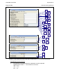
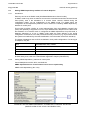
GTW/EN AP/C80
Page 16/84
Application
PACiS GTW gateway
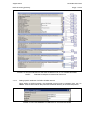
13.
SOE file support (No / Yes (Standard) / Yes (Microsol)): set to ‘Yes’ if SOE file
management is supported by the SCADA
14.
SOE file base address: this attribute is significant only if SOE file support is not set
to No.
15.
SOE file nb max of events (range [10, 4200], step 1): this attribute is significant only
if SOE file support is not set to No.
16.
nb max of SOE files (range [1,99], step 1): this attribute is significant only if SOE file
support is not set to No.
17.
Buffer overflow support (No / Yes): this attributes defines if the buffer overflow is
managed. If set to Yes the following attribute is significant and has to be updated.
18.
Buffer overflow address (No / Yes): this attributes defines the address of the buffer
overflow datapoint sent to SCADA.
19.
Quality value for 'Jammed' state (valid \ IV invalid): this attribute defines the value
of the Quality Descriptor field when the event to transmit in the 'Jammed' state.
20.
Quality value for 'Unknown' state (Not topical only \ Not topical and IV invalid): this
attribute defines the value of the Quality Descriptor field when the event to transmit in
the 'Unknown' state.
21.
Balanced mode (No/Yes): this attribute defines balanced mode if set to yes.
22.
Balanced mode retry number: number of unsuccessful polls before the slave is
declared disconnected.
23.
Balanced mode link timeout: delay.
24.
SQ value for TS: SQ flag value for TS data points (refer to the CT Chapter).
25.
SQ value for TM: SQ flag value for TM data points.
26.
SQ value for Counters: SQ flag value for counter data points.
27.
Gap address to split: Max_Gaps_DP value, used to adjust the passband (refer to
the CT Chapter).
Application
GTW/EN AP/C80
PACiS GTW gateway
Page 17/84
FIGURE 15: SETTING PROTOCOL AND SOE ATTRIBUTES OF A T101 SCADA NETWORK
NOTE :
4.4.1.4
Disturbance tab-pane is reserved for future use.
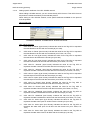
Setting specific attributes of a DNP3 SCADA network
When adding a SCADA network, the supported protocol must be updated. Here, set it to
‘DNP3’. Then SCADA network tab-panes are refreshed relatively to the selected protocol.
FIGURE 16: SETTING GENERAL ATTRIBUTES OF A SCADA NETWORK
GTW/EN AP/C80
Page 18/84
Application
PACiS GTW gateway
When setting a DNP3 SCADA network, some specific attributes available for the protocol
must be updated (Protocol tab-pane):
FIGURE 17: SETTING PROTOCOL TYPE OF A SCADA NETWORK
4.4.1.5
1.
Comm. Interface (Serial port communication / UDP / TCP/IP): Type of DNP3
communication (‘DNP3 Serial Communication’ or ‘DNP3 TCP/IP Communication)
2.
link address: (range [1, 65534], step 1) Link address of the slave
3.
TCP/IP address: Ethernet address if GTW is communicating to SCADA through
TCP/IP
4.
SPS/DPS class: (1 / 2 / 3) Class for SPS/DPS datapoints
5.
MV class: (1 / 2 / 3) Class for MV datapooints
6.
Counter class: (1 / 2 / 3) Class for counter datapoints
7.
IP port number: if GTW is communicating to SCADA through TCP/IP
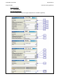
Setting specific attributes of a T104 SCADA network
When adding a SCADA network, the supported protocol must be updated (1). Here, set it to
‘T104’. For this protocol an additional attribute 'time reference' (2) is displayed and has to
be set. Available values for this attribute are UTC or local. This attributes defines which time
reference is used to stamp events transmitted to SCADA.
(1)
(2)
FIGURE 18: SETTING PROTOCOL TYPE OF A T104 SCADA NETWORK
Application
GTW/EN AP/C80
PACiS GTW gateway
Page 19/84
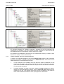
When setting a T104 SCADA network, some specific attributes available for the protocol
must be updated (Protocol and SOE tab-panes):
1.
TCP/IP address of the GTW
2.
ASDU common address (range [1, 65534], step 1)
3.
information object length (Address on 8 bits.16 bits / Address on 16 bits.8 bits /
Address on 8 bits.8 bits.8 bits / Address on 24 bits (3 bytes))
4.
MV periodic cycle (range [0 s, 65534 s], step 1 s)
5.
background scan cycle (range [0 s, 65535 s], step 1 s)
6.
T0: connection time-out (range [1 s, 255 s], step 1 s)
7.
T1: APDU time-out (range [1 s, 255 s], step 1 s)
8.
T2: acknowledgement time-out (range [1 s, 255 s], step 1 s)
9.
T3: test frame time-out (range [1 s, 255 s], step 1 s)
10.
K: sent unack. frames (window size) (range [1, 255], step 1)
11.
W: ack. received frames (window size) (range [1, 255], step 1)
12.
max command delay (range [0 s, 32767 s], step 1 s)
13.
quality value for 'Jammed' state: (Valid/ Invalid) this attribute defines the value of the
Quality Descriptor field when the event to transmit is an xPS in the 'Jammed' State.
14.
quality value for toggling xPS( BL only (blocked) / IV only (invalid) : this attribute
defines the value of the Quality Descriptor field when the event to transmit is an xPS
in the ‘Toggling’ state.
15.
quality value for 'unknown' state: (Not topical/ Not topical and IV invalid) this
attribute defines the value of the Quality Descriptor field when the event to transmit is
an xPS in the 'Unknown' State.
16.
SOE file support (No / Yes (Standard) / Yes (Microsol)): set to ‘Yes’ if SOE file
management is supported by the SCADA.
17.
SOE file base address: this attribute is significant only if SOE file support is not set
to No.
18.
SOE file nb max of events (range [10,4200], step 1): this attribute is significant only
if SOE file support is not set to No.
19.
nb max of SOE files (range [1,99], step 1): this attribute is significant only if SOE file
support is not set to No.
20.
Disturb file upload (No / Yes: this attributes defines if the disturbance file is
managed. If set to Yes the following attribute is significant and has to be updated.
21.
Disturb file base address
22.
Nb max of disturb files
23.
Buffer overflow support (No / Yes): this attributes defines if the buffer overflow is
managed. If set to Yes the following attribute is significant and has to be updated.
24.
Buffer overflow address (No / Yes): this attributes defines the address of the buffer
overflow datapoint sent to SCADA.
GTW/EN AP/C80
Page 20/84
Application
PACiS GTW gateway
FIGURE 19: SETTING PROTOCOL AND SOE ATTRIBUTES OF A T104 SCADA NETWORK
Configuration rules and checks
•
The following constraints between the attributes must be respected:
"SOE file nb of events" > "'full' SOE file nb of events"
"T2" < "T1"
"T3" > "T1"
"W" ≤ "K"
Application
GTW/EN AP/C80
PACiS GTW gateway
4.4.1.6
Page 21/84
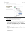
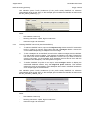
Setting specific attributes of a MODBUS SCADA network
When adding a SCADA network, the supported protocol must be updated. Then SCADA
network tab-panes depend the selected protocol.
FIGURE 20: SETTING PROTOCOL TYPE OF A MODBUS SCADA NETWORK
When setting a MODBUS SCADA network, some specific attributes available for the protocol
must be updated (Protocol tab-pane):
FIGURE 21: SETTING SPECIFIC ATTRIBUTES OF A MODBUS SCADA NETWORK
1.
Comm. Interface* (Serial port communication / Modbus TCP/IP)
2.
link address (range [1, 247], step 1): Link address of the slave
3.
TCP/IP address: Ethernet address (if “MODBUS TCP/IP” is selected)
4.
parity: (None / Odd / Even) used at communication level
5.
IP port number: if GTW is communicating through Modbus TCP/IP
CAUTION (*) : The Comm. Interface with The Modbus IP setting is reserved for future
use.
GTW/EN AP/C80
Page 22/84
4.4.1.7
Application
PACiS GTW gateway
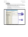
Setting specific attributes of a CDC type II SCADA network
When adding a SCADA network, the supported protocol must be updated (1). Here, set it to
‘CDC type II’. Then SCADA network tab-panes are refreshed relatively to the selected
protocol.
(1)
FIGURE 22: SETTING PROTOCOL TYPE OF A CDC TYPE II SCADA NETWORK
When setting a CDC type II SCADA network, some specific attributes available for the
protocol must be updated (Protocol tab-pane):
1.
T0: connection time-out (range [1 s, 255 s], step 1 s)
2.
minimal int value for MV (range [-2048, 0], step 1)
3.
maximal int value for MV (range [0,2047], step 1)
4.
int value for invalid MV (None / 2047 / -2048)
(1)
(2)
(3)
(4)
FIGURE 23: SETTING SPECIFIC ATTRIBUTES OF A CDC TYPE II SCADA NETWORK
Application
GTW/EN AP/C80
PACiS GTW gateway
4.4.1.8
Page 23/84
Setting specific attributes of an OPC SCADA network
When adding a SCADA network, you can choose directly OPC Protocol. Then OPC Protocol
tab-panes are refreshed relatively to the selected protocol.
When setting an OPC SCADA network, some specific attributes available for the protocol
must be updated:
General tab-pane
FIGURE 24: GENERAL ATTRIBUTES OF AN OPC PROTOCOL
OPC values tab pane
1.
OPC value for ‘Reset’ (byte format): indicates the value for the Tag OPC to represent
the state Reset for all SPS with the format byte (0 to 255).
2.
OPC value for ‘Reset’ (bool format): indicates the value for the Tag OPC to represent
the state Reset for all SPS with the format bool (0 for False,1 for True).
3.
OPC value for ‘Set’ (byte format): indicates the value for the Tag OPC to represent
the state Set for all SPS with the format byte (0 to 255).
4.
OPC value for ‘Set’ (bool format): indicates the value for the Tag OPC to represent
the state Jammed for all SPS with the format bool (0 for False,1 for True).
5.
OPC value for ‘Jammed’ (byte format): indicates the value for the Tag OPC to
represent the state Jammed for all DPS with the format byte (0 to 255).
6.
OPC value for ‘Jammed’ (bool format): indicates the value for the Tag OPC to
represent the state Jammed for all DPS with the format bool (0 for False,1 for True).
7.
OPC value for ‘Open’ (byte format): indicates the value for the Tag OPC to represent
the state Open for all DPS with the format byte (0 to 255).
8.
OPC value for ‘Open’ (bool format): indicates the value for the Tag OPC to represent
the state Open for all DPS with the format bool (0 for False,1 for True).
9.
OPC value for ‘Closed’ (byte format): indicates the value for the Tag OPC to
represent the state Close for all DPS with the format byte (0 to 255).
10.
OPC value for ‘Closed’ (bool format): indicates the value for the Tag OPC to
represent the state Close for all DPS with the format bool (0 for False,1 for True).
11.
OPC value for ‘Undefined’ (byte format): indicates the value for the Tag OPC to
represent the state Undefined for all DPS with the format byte (0 to 255).
12.
OPC value for ‘Undefined’ (bool format): indicates the value for the Tag OPC to
represent the state Undefined for all DPS with the format bool (0 for False,1 for True).
13.
OPC value for ‘Order open’ (byte format): indicates the value for the Tag OPC to
represent the state order open for all DPC with the format byte (0 to 255).
14.
OPC value for ‘Order open’ (bool format): indicates the value for the Tag OPC to
represent the state order open for all DPC with the format bool (0 for False,1 for
True).
15.
OPC value for ‘Order close’ (byte format): indicates the value for the Tag OPC to
represent the state order close for all DPC with the format byte (0 to 255).
GTW/EN AP/C80
Page 24/84
Application
PACiS GTW gateway
16.
OPC value for ‘Order close’ (bool format): indicates the value for the Tag OPC to
represent the state order close for all DPC with the format bool (0 for False,1 for
True).
17.
OPC value for ‘Order reset’ (byte format): indicates the value for the Tag OPC to
represent the state order reset for all SPC with the format byte (0 to 255).
18.
OPC value for ‘Order reset’ (bool format): indicates the value for the Tag OPC to
represent the state order reset for all SPC with the format bool (0 for False,1 for
True).
19.
OPC value for ‘Order set’ (byte format): indicates the value for the Tag OPC to
represent the state order set for all SPC with the format byte (0 to 255).
20.
OPC value for ‘Order set’ (bool format): indicates the value for the Tag OPC to
represent the state order set for all SPC with the format bool (0 for False,1 for True).
(1)
(2)
(3)
(4)
(5)
(6)
(7)
(8)
(9)
(10)
(11)
(12)
(13)
(14)
(15)
(16)
(17)
(18)
(19)
(20)
FIGURE 25: SETTING OPC VALUES ATTRIBUTES OF AN OPC SCADA NETWORK
Application
GTW/EN AP/C80
PACiS GTW gateway
Page 25/84
OPC qualities tab pane
1.
OPC quality for ‘SelfCheckFault’: indicates the value for the Tag OPC quality to
represent the IEC61850 quality set to SelfCheckFault for all datapoints (0 to 65535).
2.
OPC quality for ‘Unknown’: indicates the value for the Tag OPC quality to represent
the IEC61850 quality set to Unknown for all datapoints (0 to 65535).
3.
OPC quality for ‘Toggling’: indicates the value for the Tag OPC quality to represent
the IEC61850 quality set to Toggling for all datapoints (0 to 65535).
4.
OPC quality for ‘Suppressed’ indicates the value for the Tag OPC quality to represent
the IEC61850 quality set to Suppressed for all datapoints (0 to 65535).
5.
OPC quality for ‘Forced’: indicates the value for the Tag OPC quality to represent the
IEC61850 quality set to Forced for all datapoints (0 to 65535).
6.
OPC quality for ‘Substituted’: indicates the value for the Tag OPC quality to represent
the IEC61850 quality set to Substituted for all datapoints (0 to 65535).
7.
OPC quality for ‘Undefined’: indicates the value for the Tag OPC quality to represent
the IEC61850 quality set to Undefined for all MPS,MV,Counter (0 to 65535).
8.
OPC quality for ‘OverRange’: indicates the value for the Tag OPC quality to represent
the IEC61850 quality set to OverRange for all MV,Counter (0 to 65535).
9.
OPC quality for ‘OpenCircuit’: indicates the value for the Tag OPC quality to represent
the IEC61850 quality set to OpenCircuit for all MV (0 to 65535).
10.
OPC quality for ‘LLLThreshold’: indicates the value for the Tag OPC quality to
represent the IEC61850 quality set to LLLThreshold for all MV (0 to 65535).
11.
OPC quality for ‘LLThreshold’: indicates the value for the Tag OPC quality to
represent the IEC61850 quality set to LLThreshold for all MV (0 to 65535).
12.
OPC quality for ‘LThreshold’: indicates the value for the Tag OPC quality to represent
the IEC61850 quality set to LThreshold for all MV (0 to 65535).
13.
OPC quality for ‘HThreshold’: indicates the value for the Tag OPC quality to represent
the IEC61850 quality set to HThreshold for all MV (0 to 65535).
14.
OPC quality for ‘HHThreshold’: indicates the value for the Tag OPC quality to
represent the IEC61850 quality set to HHThreshold for all MV (0 to 65535).
15.
OPC quality for ‘HHHThreshold’: indicates the value for the Tag OPC quality to
represent the IEC61850 quality set to HHHThreshold for all MV (0 to 65535).
16.
OPC quality for ‘Jammed’: indicates the value for the Tag OPC quality to represent
the IEC61850 quality set to Jammed for all DPS (0 to 65535).
17.
OPC quality for ‘Undefined’: indicates the value for the Tag OPC quality to represent
the IEC61850 quality set to Undefined for all DPS (0 to 65535).
18.
OPC quality for ‘Valid Set/Closed’: indicates the value for the Tag OPC quality to
represent the IEC61850 quality set to Set or Closed for all SPS/DPS (0 to 65535).
19.
OPC quality for ‘Valid Reset/Opened’: indicates the value for the Tag OPC quality to
represent the IEC61850 quality set to Reset or Opened for all SPS/DPS (0 to 65535).
GTW/EN AP/C80
Page 26/84
Application
PACiS GTW gateway
(1)
(2)
(3)
(4)
(5)
(6)
(7)
(8)
(9)
(10)
(11)
(12)
(13
(14)
(15)
(16)
(17)
(18)
(19)
FIGURE 26: SETTING OPC QUALITIES ATTRIBUTES OF AN OPC SCADA NETWORK
4.4.1.9
Setting specific attributes of an IEC 61850 SCADA network
When setting an IEC 61850 SCADA network the following attributes must be updated:
1.
short name and long name: used for logging, alarms, …
2.
TCP/IP address of the GTW on the SCADA network
3.
Check Local/Remote (Yes / No) of the GTW on SCADA network
This attribute "Check Local/Remote" defines if the SubstationLocal/Remote information has
to be used by an IEC61850/IEC61850 gateway. The Substation Local/Remote xPS comes
from the lower IEC61850 network.
If the L/R is managed (attribute to YES), the controls coming from the upper network:
•
are sent to the lower network if the Substation mode is “Remote” and if the controls
are dependant of the L/R mode.
•
are sent to the lower network if the controls are independant of the L/R mode.
•
are negatively acknowledged (“bay-substation mode fault” ack) if the Substation
mode is “Local” and if the controls are dependant of the L/R mode
If the L/R is not managed (attribute to NO), the controls coming from the upper network are
sent to the lower network whatever is the L/R state.
Application
GTW/EN AP/C80
PACiS GTW gateway
Page 27/84
Configuration rules and checks
•
The "TCP/IP address" value of a device must be unique among all the devices per
Ethernet Network.
FIGURE 27: SETTING ATTRIBUTES OF AN IEC 61850 SCADA PROTOCOL
4.4.1.10
Setting general attributes of a T101-SAS SCADA network
When adding a SCADA network, the supported protocol must be updated (1). Here, set it to
‘T101-SAS’. Then SCADA network tab-panes are refreshed relatively to the selected
protocol.
When setting a T101-SAS SCADA network the following attributes must be updated:
1.
short name and long name: used for logging, alarms, …
FIGURE 28: SETTING PROTOCOL TYPE OF A T101-SAS SCADA NETWORK
When setting a T101-SAS SCADA network, some specific attributes available for the
protocol must be updated (Protocol tab-pane):
1.
ASDU common address length (1 byte / 2 bytes)
2.
ASDU common address (range [1, 65534], step 1)
3.
Address structure (address on 8 bits .8 bits.8 bits)
4.
Frame max length (range [1, 255], step 1)
5.
MV periodic cycle (in s) (range [0 s, 65534 s], step 1 s)
6.
Binary time size (CP24 Time2A 3bytes / CP56 Time2A 7bytes)
FIGURE 29: SETTING PROTOCOL OF A T101-SAS SCADA NETWORK
GTW/EN AP/C80
Page 28/84
4.4.2
Application
PACiS GTW gateway
Defining addressing mapping of SCADA legacy network
To transmit information between PACiS system and SCADA, a SCADA legacy network is
used. So, each concerned data must have a specific address on this network relatively to its
protocol. General modelling of a SCADA legacy network address mapping can be done. At
SCE level, a SCADA legacy network owns a “SCADA mapping” object, that is split in
categories of mapping on a per datapoint kind basis. In each category of mapping,
elementary SCADA addresses can be created. This mapping is implicitly created at SCADA
network creation.
Addressing MPS datapoint on SCADA legacy network is not available.
Entry point of
SCADA
Categories per
datapoint kind
basis
S0391ENc
FIGURE 30: STRUCTURE OF THE ADDRESSING MAPPING OF A LEGACY SCADA NETWORK
Configuration rules and checks
•
In the SCADA Mapping, the address identification of each "Gtw xxx addr." must be
unique. For T101 and T104 protocols, the uniqueness constraint is applicable only for
addresses of the same type. Addresses of different types can have identical
addresses and therefore this does not lead to an error but to a warning.
•
With a DNP3 protocol, a "Gtw MV addr.", which is the SCADA address of a "Tap pos
ind" datapoint, must have its "Format" attribute set to the "Natural" value.
The addressing mapping of a SCADA legacy network can also be defined by using “Edit
SCADA mapping“ This will open the list of datapoints having path, short name, long name,
address, label, timetag, inversion. See SCE_HI chapter.
Application
GTW/EN AP/C80
PACiS GTW gateway
Page 29/84
FIGURE 31: EDIT SCADA MAPPING
4.4.2.1
Defining a SCADA address for an SPS datapoint
Addition of a SCADA address for an SPS datapoint is done under SCE via the “Object entry”
area at SCADA SPS mapping level by clicking on mouse’s right button.
FIGURE 32: ADDING A SCADA SPS ADDRESS
GTW/EN AP/C80
Page 30/84
Application
PACiS GTW gateway
Once added, SCADA SPS address attributes must be set at SCE level:
1.
short name of the address used for internal SCE identification
For T101/T104 protocols:
2.
object address
3.
priority level (range [1,255], step 1) gives the priority of emission (1: higher). Only
significant if Event attribute is different from ‘No’. Is fixed to 1 for T104 protocol.
4.
Event (No / Yes with time tag / Yes without time tag): when set to ‘Yes with time tag’,
indicates that change of state of the datapoint are transmitted spontaneously with
time Tag.
5.
Event record (Does not involved in a transfert of file / Create a RECORD EVENT if
there is not it current / Add to the current record EVENT / Create a RECORD EVENT
and adds to the current record EVENT): when set to a value different from ‘Does not
involved in a transfer of file’, indicates if change of state of the datapoint must be
saved in Sequence of Event file. Values different from ‘Does not involved in a transfer
of file’ are associated to the same treatment, because only one SOE file is managed
by the GTW. The set of available values is maintained for compatibility with MiCOM
GTW addressing in PACiSGTW.
6.
Inversion (No / Yes): Indicates that the datapoint value needs to be inverted before
transmission.
7.
Background scan (No / Yes): indicates if the datapoint belongs to the background
scan cycle.
8.
Group ([0..16)] / 0=no group) (range [0,16], step 1) indicates to which “T101/T104
General Interrogation group” the datapoint is assigned. 0 means ‘no group’
assignation.
For DNP3 protocol:
9.
object address - index.
10.
Event (No / Yes with time tag): when set to ‘Yes with time tag’, indicates if change of
state of the datapoint are transmitted spontaneously with time Tag.
11.
Inversion (No/Yes): indicates that the datapoint value needs to be inverted before
transmission
For Modbus protocol:
12.
object address – register
13.
Inversion (No/Yes): indicates that the datapoint value needs to be inverted before
transmission
For CDC type II protocol
14.
Sequence number [0…63]
15.
OFF-offset [0…15]
16.
CHN-device number[0…15]
17.
Sending mode (Static only / Event only / Static and Event)
18.
PPU- sequence of event group [1..25] (static mode only) (range [1,25], step 1)
19.
EVT – rang in PPU [0..47] (event mode only) (range [0,47], step 1)
20.
Inversion (No/Yes): indicates that the datapoint value needs to be inverted before
transmission.
Application
GTW/EN AP/C80
PACiS GTW gateway
Page 31/84
For OPC protocol:
21.
OPC address: indicates the name’s tag for OPC (limited to 48 characters). The
character “.” indicates that the name is hierarchical.
22.
Historization (No / Yes): indicates if this tag is sent at historic timer frequency (refer
to section 7.3.1 of chapter GTW/EN CT).
23.
Format (boolean / byte): indicates the type of value which is associated with the tag.
Boolean is for VT_BOOL a boolean (True/False) value. A value of 0xFFFF (all bits 1)
indicates True; a value of 0 (all bits 0) indicates False. No other value is valid. Byte is
for VT_UI1 an unsigned 1-byte character.
24.
Inversion (No/Yes): indicates that the datapoint value needs to be inverted before
transmission
For T101-SAS protocol:
25.
short name of the address used for internal SCE identification
26.
object address – register
27.
Inversion (No/Yes): indicates that the datapoint value needs to be inverted before
transmission
28.
Send in GI (No/Yes): indicates if the datapoint is included into the General
Interrogation
GTW/EN AP/C80
Application
Page 32/84
PACiS GTW gateway
T101/T104
(1)
(2)
(3)
(4)
(5)
(6)
(7)
(8)
DNP3
(9)
(10)
(11)
Modbus
(12)
(13)
CDC type II
(14)
(15)
(16)
(17)
(18)
(19)
(20)
OPC
(21)
(22)
(23)
(24)
SAS
(25)
(26)
(27)
(28)
FIGURE 33: DEFINING A SCADA ADDRESS FOR AN SPS DATAPOINT
Application
GTW/EN AP/C80
PACiS GTW gateway
4.4.2.2
Page 33/84
Defining a SCADA address for a DPS datapoint
Addition of a SCADA address for a DPS datapoint is done under SCE via the “Object entry”
area at SCADA DPS mapping level by clicking on mouse’s right button.
FIGURE 34: ADDING A SCADA DPS ADDRESS
Once added, SCADA DPS address attributes must be set at SCE level:
1.
short name of the address used for internal SCE identification
For T101 protocol:
2.
priority level (from 1 to 255): gives the priority of emission (1: higher). Only
significant if Event attribute is different from ‘No’. Is fixed to 1 for T104 protocol.
3.
Event (No / Yes with time tag / Yes without time tag): when set to ‘Yes with time tag’
(resp. ‘Yes without time tag’) indicates if change of state of the datapoint are
transmitted spontaneously with (resp. without) time tag
4.
Event record (Does not involved transfert of file / Create a RECORD EVENT if there
is not it current / Add to the current record EVENT / Create a RECORD EVENT and
adds to the current record EVENT):
when set to a value different from ‘Does not involved in a transfer of file’ indicates if
change of state of the datapoint must be saved in Sequence of Event file.
Values different from ‘Does not involved in a transfer of file’ are associated to the
same treatment, because only one SOE file is managed by the GTW. The set of
available values is maintained for compatibility with MiCOM GTW addressing in
PACiS GTW.
5.
Inversion (No/Yes): indicates that the datapoint value needs to be inverted before
transmission
6.
Background scan (No/Yes): indicates if the datapoint belongs to the background
scan cycle
7.
Group ([0..16]) / 0 = no group): indicates to which “T101/T104 General Interrogation
group” the datapoint is assigned. 0 means ‘no group’ assignation
8.
object address: for PACiS GTW, only one address is useable to transmit DPS value.
GTW/EN AP/C80
Page 34/84
Application
PACiS GTW gateway
For DNP3 protocol:
9.
Event (No / Yes with time tag): when set to ‘Yes with time tag’ indicates if changes of
state of the datapoint are transmitted spontaneously with time tag
10.
Inversion (No/Yes): indicates that the datapoint value needs to be inverted before
transmission
11.
object address: index
For Modbus protocol:
12.
Inversion (No/Yes): indicates that the datapoint value needs to be inverted before
transmission
13.
object address - register: for PACiS GTW, only one address is useable to transmit a
DPS value.
For CDC type II protocol:
14.
Sending mode (Static only / Event only / Static and Event)
15.
Inversion (No/Yes): indicates that the datapoint value needs to be inverted before
transmission
16.
SQN – sequence number 50..63] (static mode only):
17.
OFF – offset [0..15]:
18.
CHN – device number [0..15]
19.
PPU – sequence of event group [1..25] (event mode only):
20.
EVT – rank in PPU [0..47] (event mode only)
For T104 protocol:
21.
priority level (from 1 to 255): gives the priority of emission (1: higher). Only
significant if Event attribute is different from ‘No’. Is fixed to 1 for T104 protocol.
22.
Event (No / Yes with time tag / Yes without time tag): when set to ‘Yes with time tag’
(resp. ‘Yes without time tag’) indicates if change of state of the datapoint are
transmitted spontaneously with (resp. without) time tag
23.
Event record (Does not involved transfert of file / Create a RECORD EVENT if there
is not it current / Add to the current record EVENT / Create a RECORD EVENT and
adds to the current record EVENT):
when set to a value different from ‘Does not involved in a transfer of file’ indicates if
change of state of the datapoint must be saved in Sequence of Event file.
Values different from ‘Does not involved in a transfer of file’ are associated to the
same treatment, because only one SOE file is managed by the GTW. The set of
available values is maintained for compatibility with MiCOM GTW addressing in
PACiS GTW.
24.
Inversion(No/Yes): indicates that the datapoint value needs to be inverted before
transmission
25.
Background scan (No/Yes): indicates if the datapoint belongs to the background
scan cycle
26.
Group ([0..16]) / 0 = no group): indicates to which “T101/T104 General Interrogation
group” the datapoint is assigned. 0 means ‘no group’ assignation
27.
object address: for PACiS GTW, only one address is useable to transmit DPS value.
Application
GTW/EN AP/C80
PACiS GTW gateway
Page 35/84
For T101-SAS protocol:
28.
Inversion (No/Yes): indicates that the datapoint value needs to be inverted before
transmission
29.
Send in GI (No/Yes): indicates if the datapoint is included into the General
Interrogation
30.
object address – register
For OPC protocol:
31.
OPC address (mono addressing): indicates the name’s tag for OPC (limited to 48
characters). The character “.” indicates that the name is hierarchical.
32.
double address usage ( No / Yes): this attribute defines if double addressing
mechanism is used or not. If this attribute is set to Yes attributes (22) and (23) must
be defined (refer to section 7.3.2 of chapter GTW/EN CT).
33.
Historization ( No /Yes): indicates if this tag is sent at historic timer frequency (refer
to section 7.3.1 of chapter GTW/EN CT).
34.
format ( Boolean / Byte): indicates the type of value which is associated with the tag.
Boolean is for VT_BOOL a boolean (True/False) value. A value of 0xFFFF (all bits 1)
indicates True; a value of 0 (all bits 0) indicates False. No other value is valid. Byte is
for VT_UI1 an unsigned 1-byte character.
35.
Inversion ( No / Yes): before being transmitted the value of the DPS is inverted as
defined here after:
- JAMMED (00) is replaced by UNDEFINED and vice-versa
- OPEN (01) is replaced by CLODSE (10) and vice versa
36.
open state address: this attribute is only significant if attribute double address
usage is set to Yes. It defines the OPC tag name for the OPEN state
37.
Closed state address: this attribute is only significant if attribute double address
usage is set to Yes. It defines the OPC tag name for the CLOSE state
GTW/EN AP/C80
Page 36/84
Application
PACiS GTW gateway
FIGURE 35: DEFINING A SCADA ADDRESS FOR A DPS DATAPOINT
Application
GTW/EN AP/C80
PACiS GTW gateway
4.4.2.3
Page 37/84
Defining a SCADA address for a MV datapoint
Addition of a SCADA address for a MV datapoint is done under SCE via the “Object entry”
area at SCADA MV mapping level by clicking on mouse’s right button.
FIGURE 36: ADDING A SCADA MV ADDRESS
Once added, SCADA MV address attributes must be set at SCE level:
1.
short name of the address used for internal SCE identification
For T101/T104 protocols:
2.
object address:
3.
priority level (range [1,255], step 1) gives the priority of emission (1: higher). Only
significant if Event attribute is different from ‘No’. Is fixed to 1 for T104 protocol.
4.
Event (No / Yes with time tag / Yes without time tag): when set to ‘Yes with time tag’,
indicates that changes of state of the datapoint are transmitted spontaneously with
time Tag.
5.
Event record (No / Yes): indicates if the datapoint has to be recorded in the SOE file
6.
Format (Normalized / Adjusted / Float): transmission format.
7.
cycle type (None / Periodic / Background scan): indicates which transmission cycle
the MEAS belongs to.
8.
Group ([0..16)] / 0=no group): indicates to which “T101/T104 General Interrogation
group” the datapoint is assigned to. 0 means ‘no group’ assignation.
9.
minimum value ( range [-3.4E38, +3.4E38]): minimum scaled value. Not used if
minimum value = maximum value.
10.
maximum value ( range [-3.4E38, +3.4E38]): maximum scaled value. Not used if
minimum value = maximum value.
GTW/EN AP/C80
Page 38/84
Application
PACiS GTW gateway
For DNP3 protocol:
11.
object address [0..65535].
12.
Event (No / Yes with time tag): when set to ‘Yes with time tag’, indicates if changes of
state of the datapoint are transmitted spontaneously with time Tag.
13.
Format (Natural / Adjusted).
14.
minimum value ( range [-3.4E38, +3.4E38]): minimum scaled value. Not used if
minimum value = maximum value.
15.
maximum value ( range [-3.4E38, +3.4E38]): maximum scaled value. Not used if
minimum value = maximum value
16.
defined as counter ( Yes/ No).
For Modbus protocol:
17.
object address - register
18.
Format (Natural / Unsigned normalized / Signed normalized): transmission format.
19.
Precision (8..16) (range [8,16),step 1): number of transmitted bits.
20.
minimum value ( range [-3.4E38, +3.4E38]): minimum scaled value. Not used if
minimum value = maximum value.
21.
maximum value ( range [-3.4E38, +3.4E38]): maximum scaled value. Not used if
minimum value = maximum value.:
For CDC type II protocol:
22.
SQN - sequence number [64..255]
23.
CHN - device number [0..15] (range [0,15], step 1 except 14)
24.
minimum value ( range [-3.4E38, +3.4E38]): minimum scaled value. Not used if
minimum value = maximum value.
25.
maximum value ( range [-3.4E38, +3.4E38]): maximum scaled value. Not used if
minimum value = maximum value.:
For OPC protocol:
26.
OPC address: indicates the name’s tag for OPC (limited to 48 characters). The
character “.” indicates that the name is hierarchical. For OPC MV the format is VT_R4
(an IEEE 4-byte real value)
For T101-SAS protocol:
27.
short name of the address used for internal SCE identification
28.
object address [0..65535]
29.
Format (Normalized / Ajusted / Float): transmission format
30.
cycle type (None / Periodic): indicates which transmission cycle the MEAS belongs
to
31.
minimum value (range [-3.4E38, +3.4E38]): minimum scaled value. Not used if
minimum value = maximum value
32.
maximum value (range [-3.4E38, +3.4E38]): maximum scaled value. Not used if
minimum value = maximum value
Application
GTW/EN AP/C80
PACiS GTW gateway
Page 39/84
FIGURE 37: DEFINING A SCADA ADDRESS FOR A MV DATAPOINT
T101-SAS does not support measurements except Tap Position Indicator (TPI).
GTW/EN AP/C80
Application
Page 40/84
4.4.2.4
PACiS GTW gateway
Defining a SCADA address for a Counter datapoint
Addition of a SCADA address for a Counter datapoint is done under SCE via the “Object
entry” area at SCADA Counter mapping level by clicking on mouse’s right button.
NOTA: when one handles the counters (freeze, reset, etc....) this touches only the increase
towards the SCADA, the counters are not modified on the C264 level, only on the level
protocol
FIGURE 38: ADDING A SCADA COUNTER ADDRESS
Once added, SCADA Counter address attributes must be set at SCE level:
1.
short name and long name of the address used for internal SCE identification
For T101/T104 protocols:
2.
object address
3.
priority level (range [1,255], step 1) gives the priority of emission (1: higher). Only
significant if Event attribute is different from ‘No’. Is fixed to 1 for T104 protocol.
4.
Event (No / Yes with time tag / Yes without time tag): when set to ‘Yes with time tag’,
indicates that change of state of the datapoint are transmitted spontaneously with
time Tag.
5.
Event record (No / Yes): indicates if the datapoint has to be recorded in the SOE file
6.
Group ([0..4] / 0=no group): indicates which “T101/T104 General Interrogation
group” the datapoint is assigned to. 0 means ‘no group’ assignation.
For DNP3 protocol:
7.
object address [0..65535].
8.
Event (No / Yes with time tag): when set to ‘Yes with time tag’, indicates if changes of
state of the datapoint are transmitted spontaneously with time Tag.
For Modbus protocol:
9.
object address - register
10.
Format (Natural / Unsigned normalized): transmission format.
Application
GTW/EN AP/C80
PACiS GTW gateway
Page 41/84
For CDC type II protocol:
11.
SQN - sequence number [64..255]
12.
CHN - device number [0..15] (range [0,15], step 1 except 14)
For OPC protocol:
13.
OPC address: indicates the name’s tag for OPC (limited to 48 characters). The
character “.” indicates that the name is hierarchical. For OPC counter the format is
VT_I4 (a 4-bytes integer value)
For T101-SAS protocol:
14.
Object address
T101-SAS does not support Counter datapoints.
FIGURE 39: DEFINING A SCADA ADDRESS FOR A COUNTER DATAPOINT
NOTE:
Energy values transmitted as counter for DNP3 & CDC II protocol.
GTW/EN AP/C80
Application
Page 42/84
4.4.2.5
PACiS GTW gateway
Defining a SCADA address for a SPC datapoint
Addition of a SCADA address for a SPC datapoint is done under SCE via the “Object entry”
area at SCADA SPC mapping level by clicking on mouse’s right button.
FIGURE 40: ADDING A SCADA SPC ADDRESS
Once added, SCADA SPC address attributes must be set at SCE level:
1.
short name of the address used for internal SCE identification
For T101/T104 protocols:
2.
object address
3.
SCADA execute order type (Select execute / Direct execute): this attribute defines
which kind of sequence is used by the SCADA to send a control to the datapoint.
4.
SBO time-out (range [0 s, 65535 s], step 1 s): time-out PACiS system has to
acknowledge the selection.
For DNP3 protocol:
5.
object address [0..65535]
6.
SCADA execute order type (Select execute / Direct execute): this attribute defines
which kind of sequence is used by the SCADA to send a control to the datapoint.
For Modbus protocol:
7.
object address - register
For CDC type II protocol:
8.
SQN - block number [0..63]
9.
CHN - device number [0..15] (range [0,15], step 1 except 14)
10.
SCADA execute order type (Select execute / Direct execute): this attribute defines
which kind of sequence is used by the SCADA to send a control to the datapoint.
For OPC protocol:
11.
OPC address: indicates the name’s tag for OPC (limited to 48 characters). The
character “.” indicates that the name is hierarchical.
12.
format (Boolean/Byte): indicates the type of value associated to the tag. Boolean is
for VT_BOOL a boolean (True/False) value. A value of 0xFFFF (all bits 1) indicates
True; a value of 0 (all bits 0) indicates False. No other value is valid. Byte is for
VT_UI1 an unsigned 1-byte character.
Application
GTW/EN AP/C80
PACiS GTW gateway
Page 43/84
For T101-SAS Protocol
The T101-SAS protocol does not support SPC commands from SCADA to gateway.
FIGURE 41: DEFINING A SCADA ADDRESS FOR AN SPC DATAPOINT
GTW/EN AP/C80
Application
Page 44/84
4.4.2.6
PACiS GTW gateway
Defining a SCADA address for a DPC datapoint
Addition of a SCADA address for a DPC datapoint is done under SCE via the “Object entry”
area at SCADA DPC mapping level by clicking on mouse’s right button.
FIGURE 42: ADDING A SCADA DPC ADDRESS
Once added, SCADA DPC address attributes must be set at SCE level:
1.
short name of the address used for internal SCE identification
For T101/T104 protocols:
2.
object address
3.
SCADA execute order type (Select execute / Direct execute): this attribute defines
which kind of sequence is used by the SCADA to send a control to the datapoint.
4.
SBO time-out (range [0 s, 65535 s], step 1 s): time-out PACiS system has to
acknowledge the selection.
For DNP3 protocol:
5.
object address [0..65535]
6.
SCADA execute order type (Select execute / Direct execute): this attribute defines
which kind of sequence is used by the SCADA to send a control to the datapoint.
For Modbus protocol:
7.
object address - register
For CDC type II protocol:
8.
SQN - block number [0..63]
9.
CHN - device number [0..15] (range [0,15], step 1 except 14)
10.
SCADA execute order type (Select execute / Direct execute): this attribute defines
which kind of sequence is used by the SCADA to send a control to the datapoint.
Application
GTW/EN AP/C80
PACiS GTW gateway
Page 45/84
For OPC protocol:
11.
OPC address: indicates the name’s tag for OPC (limited to 48 characters). The
character “.” indicates that the name is hierarchical.
12.
double address usage (No / Yes): this attribute defines if double addressing
mechanism is used or not. If this attribute is set to Yes attributes (22) and (23) must
be defined (refer to section 7.3.2 of chapter GTW/EN CT).
13.
format (Boolean/Byte): indicates the type of value associated to the tag. Boolean is
for VT_BOOL a boolean (True/False) value. A value of 0xFFFF (all bits 1) indicates
True; a value of 0 (all bits 0) indicates False. No other value is valid. Byte is for
VT_UI1 an unsigned 1-byte character.
14.
open order address: this attribute is only significant if attribute double address
usage is set to Yes. It defines the OPC tag name for the OPEN state
15.
Closed order address: this attribute is only significant if attribute double address
usage is set to Yes. It defines the OPC tag name for the CLOSE state
For T101-SAS Protocol:
The T101-SAS protocl does not support DPC commands from SCADA to gateway.
GTW/EN AP/C80
Page 46/84
Application
PACiS GTW gateway
FIGURE 43: DEFINING A SCADA ADDRESS FOR A DPC DATAPOINT
Application
GTW/EN AP/C80
PACiS GTW gateway
4.4.2.7
Page 47/84
Defining a SCADA address for a SetPoint datapoint
Addition of a SCADA address for a SetPoint datapoint is done under SCE via the “Object
entry” area at SCADA SetPoint mapping level by clicking on mouse’s right button.
FIGURE 44: ADDING A SCADA SETPOINT ADDRESS
Once added, SCADA SetPoint address attributes must be set at SCE level:
1.
short name of the address used for internal SCE identification
For T101/T104 protocols:
2.
object address
3.
SCADA execute order type (Select execute / Direct execute): this attribute defines
which kind of sequence is used by the SCADA to send a control to the datapoint.
4.
minimal value (range [-231,231-1],step 1): available minimal value on the protocol
(used for scaling and checks)
5.
maximal value (range [-231,231-1],step 1): available maximal value on the protocol
(used for scaling and checks)
6.
format (Normalised / Adjusted / Float)
7.
SBO time-out (range [0 s, 65535 s], step 1 s): time-out PACiS system has to
acknowledge the selection.
For DNP3 protocol:
8.
object address [0..65535]
9.
SCADA execute order type (Select execute / Direct execute): this attribute defines
which kind of sequence is used by the SCADA to send a control to the datapoint.
For CDC type II protocol:xxx
10.
SQN - block number [0..15]
11.
CHN - device number [0..15] (range [0,15], step 1 except 14)
12.
minimal value (range [-231,231-1],step 1): available minimal value on the protocol
(used for scaling and checks)
13.
maximal value (range [-231,231-1],step 1): available maximal value on the protocol
(used for scaling and checks)
GTW/EN AP/C80
Page 48/84
Application
PACiS GTW gateway
For OPC protocol:
14.
OPC address
For T101-SAS protocol:
The T101-SAS protocl does not support setpoints from SCADA to gateway.
FIGURE 45: DEFINING A SCADA ADDRESS FOR A SETPOINT DATAPOINT
Application
GTW/EN AP/C80
PACiS GTW gateway
4.4.2.8
Page 49/84
Defining a SCADA address for an MPS datapoint
Addition of a SCADA address for an MPS datapoint is done under SCE via the “Object entry”
area at SCADA MPS mapping level by clicking on mouse’s right button.
FIGURE 46: ADDING A SCADA MPS ADDRESS
Once added, SCADA MPS address attributes must be set at SCE level:
1.
short name of the address used for internal SCE identification
For T101/T104 protocols:
2.
bitstring usage ( No / Yes): must be set to Yes. Indicates if the MPS is split or not.
3.
priority level (from 1 to 255): gives the priority of emission (1: higher). Only
significant if Event attribute is different from ‘No’. Is fixed to 1 for T104 protocol.
4.
Event (No / Yes with time tag / Yes without time tag): when set to ‘Yes with time tag’
(resp. ‘Yes without time tag’), indicates if change of state of the datapoint are
transmitted spontaneously with (resp. without) time tag
5.
Event record: indicates if the datapoint will be recorded in the SOE file
6.
Background scan (No/Yes): indicates if the datapoint belongs to the background
scan cycle
7.
Group ([0..16)] / 0=no group) (range [0,16], step 1) indicates to which “T101/T104
General Interrogation group” the datapoint is assigned. 0 means ‘no group’
assignation.
8.
multistate address: not used, because the MPS is not split
9.
state_X address (0 to 15 for X): indicates the T101/T104 address which will be set if
the MPS takes the value X
GTW/EN AP/C80
Page 50/84
Application
PACiS GTW gateway
(1)
(2)
(3)
(4)
(5)
(6)
(7)
(8)
(9)
FIGURE 47: GENERAL ATTRIBUTES OF AN MPS ADDRESS FOR T101/T104 PROTOCOLS
Application
GTW/EN AP/C80
PACiS GTW gateway
Page 51/84
For DNP3 protocol:
1.
bitstring usage ( No / Yes): must be set to Yes. Indicates if the MPS is split or not.
2.
Event (No / Yes with time tag / Yes without time tag): when set to ‘Yes with time tag’
(resp. ‘Yes without time tag’), indicates if change of state of the datapoint are
transmitted spontaneously with (resp. without) time tag
3.
multistate address: not used, because the MPS is not split
4.
state_X address (0 to 15 for X): indicates the DNP3 address which will be set if the
MPS takes the value X
(1)
(2)
(3)
(4)
FIGURE 48: GENERAL ATTRIBUTES OF AN MPS ADDRESS FOR DNP3 PROTOCOL
GTW/EN AP/C80
Application
Page 52/84
PACiS GTW gateway
For Modbus protocol:
1
state_X register address (0 to 15 for X): indicates the Modbus address which will be
set if the MPS takes the value X
(1)
FIGURE 49: GENERAL ATTRIBUTES OF AN MPS ADDRESS FOR MODBUS PROTOCOL
For CDC type II protocol:
FIGURE 50: GENERAL ATTRIBUTES OF AN MPS ADDRESS FOR A CDC TYPE II PROTOCOL
For OPC protocol:
12.
OPC address: indicates the name’s tag for OPC (limited to 48 characters). The
character “.” indicates that the name is hierarchical.
13.
Historization (No / Yes): indicates if this tag is sent at historic timer frequency
For MPS the format is set to VT_I2 (two-bytes integer)
(12)
(13)
FIGURE 51: DEFINING GENERAL ATTRIBUTES OF MPS ADDRESS FOR OPC PROTOCOL
Application
GTW/EN AP/C80
PACiS GTW gateway
Page 53/84
For T101-SAS protocol:
14.
short name of the address used for internal SCE identification
15.
Send in GI (No/Yes): indicates if the datapoint is included into the General
Interrogation
16.
multistate address: not used, because the MPS is not split
17.
state_X address (0 to 15 for X): indicates the T101-SAS address which will be set if
the MPS takes the value X
(1)
(2)
(3)
(4)
FIGURE 52: DEFINING GENERAL ATTRIBUTES OF MPS ADDRESS FOR T101-SAS PROTOCOL
GTW/EN AP/C80
Application
Page 54/84
4.4.2.9
PACiS GTW gateway
Defining a SCADA address for bypass synchro-check
For details about synchronised circuit-breakers, refer to the C264/C264C application chapter
(C264/EN AP).
Synchronised circuit-breaker can be controlled through SCADA network. In that case, the
SPC (resp. DPC) control of the synchronised breaker is linked to a SCADA SPC (resp. DPC)
address. Unfortunately, bypass synchro-check is not implemented in SCADA protocol. To
solve this problem, an extra SCADA SPC (resp. DPC) address that will bypass the synchrocheck, must be given to the SPC (resp. DPC) control of the breaker. At SCE level, this extra
address is linked to the SCADA address of the SPC (resp. DPC) control of the synchronised
breaker.
To define a SCADA address for bypass synchro-check:
•
Create the SCADA SPC (resp. DPC) address (A) to send SPC (resp. DPC) control of
the synchronised breaker
•
Create a SCADA SPC (resp. DPC) address (B) for bypass synchro-check in the
SCADA mapping,
•
Add the relation ‘has for bypass synchro-check address’ via the “Object entry” area at
SCADA address (A) and fill it with the SCADA address (B).
Address (B)
Address (A)
FIGURE 53: ADDING A BYPASS SYNCHRO-CHECK ADDRESS TO A SCADA SPC/DPC ADDRESS (E.G.
FOR SCADA DPC ADDRESS)
Application
GTW/EN AP/C80
PACiS GTW gateway
4.4.3
Page 55/84
Addressing datapoint on SCADA legacy network
To exchange datapoint values between station-bus sub-systems and SCADA, datapoints
should be linked to specific SCADA addresses, by adding at datapoint level the relation ‘has
for SCADA address’ (1) and filling it with the corresponding SCADA address in a preconfigured SCADA addressing mapping (refer to section 4.4.2 Defining addressing mapping
of SCADA legacy network, for SCADA mapping definition).
Addressing MPS datapoint on SCADA legacy network is not available.
FIGURE 54: REALISING SCADA ADDRESSING OF A DATAPOINT
(E.G. FOR BAY SPS DATAPOINT)
GTW/EN AP/C80
Application
Page 56/84
4.5
PACiS GTW gateway
Setting system information for GTW components
When creating a GTW, specific datapoints are automatically added in ‘system infos’ binder
(1) at GTW level or PLC sub-component.
So it is when adding a SCADA network (2) attached to a GTW. In that case, the ‘system
infos’ binder is located under the relevant added object.
SCE calls such ‘system infos’ datapoints, system datapoints.
System datapoints provide real-time statuses and controls on system software or hardware
components.
As datapoint, system datapoints must be linked to a profile. For details about datapoint and
datapoint profile configuration, refer to the C264/C264C application chapter (C264/EN AP).
Depending on its kind, the system datapoint and its relevant profile have specific attributes to
be set correctly to insure healthy behaviour of MiCOM C264 computer. Hereafter, are listed
the datapoint and profile requirements for each kind of system datapoint.
Generally system datapoints are automatically addressed in IEC61850 mapping of the
relevant MiCOM C264 computer at their creation. If manual addressing is necessary, it is
stressed in following chapters by given the associated available data object of a given
MiCOM C264 computer brick in LD0 (⇔<brick name>.<data object name>). For details
about IEC61850 addressing see section 4.3 Networking GTW on the station-bus network.
(1)
(2)
FIGURE 55: ‘SYSTEM INFOS’ BINDERS FOR A GTW
Application
GTW/EN AP/C80
PACiS GTW gateway
4.5.1
Page 57/84
Setting general system information of GTW
When creating a GTW, the following mandatory datapoints are implicitly added.
FIGURE 56: MANDATORY ‘SYSTEM INFOS’ DATAPOINTS FOR A GTW
These datapoints must be configured according to their described features:
•
Controls and statuses for functioning mode
− Mode control DPC (3): only used by the SMT to turn device functioning mode to
Maintenance or Operational/Run
IEC61850 addressing
−
Available states
⇔ LLN0.Mod
• 1
Operational/Run
Automatic at datapoint
creation
• 2
Blocked
• 3,4
Test,Test/Blocked
• 5
Maintenance
• 0
Faulty
Operating mode MPS (4): the available states of this datapoint are:
−
“STATE 0” for the Faulty mode
−
“STATE 1” for Operational mode
−
“STATE 3” for Test mode
−
“STATE 5” for Maintenance mode
An IEC address for this datapoint is defined by using SBUS automatic addressing.
GTW/EN AP/C80
Application
Page 58/84
•
PACiS GTW gateway
Control and status for database management
− DB switch ctrl SPC (1):
only used by the SMT to turn device functioning mode
to Maintenance or Operational/Run
IEC61850 addressing
⇔ DBID.ODDBSw
Available states
•
‘ON’:
Switch
Automatic at datapoint creation
•
Synchronisation status
− Synchronisation SPS (5): fixed to ‘SET’ state if device is synchronised.
IEC61850 addressing
•
Available states
⇔ C26xDIAG.SyncSt
• ‘RESET’:
Not synchronised
Automatic at datapoint creation
• ‘SET’:
Synchronised
Communication status
− Device link SPS (2): although this datapoint is under the MiCOM C264 computer,
it is not managed by it. Each IEC61850 client of the MiCOM C264 computer
computes locally this datapoint status by supervising the IEC61850 real-time link
with the MiCOM C264 computer. In fact, there are as many ‘Device link SPS’ per
MiCOM C264 computer basis as IEC61850 clients connected to the MiCOM C264
computer.
Fix to ‘SET’ state if device link is operational.
4.5.2
Setting system information of SCADA network
When creating a SCADA network, the following mandatory datapoints are implicitly added.
FIGURE 57: MANDATORY ‘SYSTEM INFOS’ DATAPOINT FOR SCADA NETWORK
Application
GTW/EN AP/C80
PACiS GTW gateway
Page 59/84
These datapoints must be configured according to their described features:
•
SCADA communication status SPS (1): fixed to ‘SET’ state if communication with the
SCADA is operational.
IEC61850 addressing
Available states
⇔ TGDIAG.CommSt<i>
• ‘RESET’:
Communication not OK
where <i> corresponds to the SCADA
number (from 0 to 3).
• ‘SET’:
Communication OK
• Manually addressed in IEC61850
DIAG brick of the MiCOM C264
computer.
Or
• IEC61850 Automatic addressing
usage.
•
SCADA redundancy status SPS (2): fixed to ‘SET’ state if redundancy with the
SCADA is active.
IEC61850 addressing
Available states
⇔ TGDIAG.RedSt<i>
• ‘RESET’:
StandBy
where <i> corresponds to the SCADA
number (from 0 to 3).
• ‘SET’:
Active
• Manually addressed in IEC61850
DIAG brick of the MiCOM C264
computer.
Or
• IEC61850 Automatic addressing
usage.
GTW/EN AP/C80
Page 60/84
4.6
Application
PACiS GTW gateway
Gateway legacy networks
The procedure is the same as creating a C264 legacy network.
4.6.1
Creating a Gateway legacy networks
To create a Gateway legacy networks on a GTW:
−
Add a network ("Modbus legacy" in example) from object entry available at Gateway
legacy networks level.
−
Update the network attributes relevant to its protocol characteristics (see following
sections).
−
Update its has for main comm. port relation and the communication port
characteristics (see section 4.2.2 Configuring a communication channel).
Time reference (UTC/local) defines which time reference is used to stamp events
transmitted to GTW.
4.6.2
Setting specific attributes of a MODBUS IED network
Additional attribute in General tab-pane:
−
Add the objects MODB_IED and MODBUS acq type; this adds the relation is
acquisition profile of to MODBUS acq type.
−
Link the MODB_IED with the brick MODB_IED.
−
To create a redundant link: Add has for aux. comm. port extra relation and type the
related port.
−
Update the attributes of MODB_IED as shown
The attributes of input Datapoint Address on IED are defined as shown in the screenshot:
"short name" and "long name": used for logs, alarms, …
1.
network address: (32 characters at most)
2.
automatic disturbance: (yes/no)
3.
localisation for disturbance file: Bay Name
Application
GTW/EN AP/C80
PACiS GTW gateway
Page 61/84
Develop the MODB_IED (icon +) and set the relation "has for acqu. profile" to the brick
MODBUS acquisition type.
Add an IED Address of relation on each IED datapoint mapping defined under MODB_IED
and associate it to the IED datapoint defined in the bay in substation.
For example:
DPS acquisition on IED:
Create one or two DPS addr. on IED:
−
1 stands for No used.
1.
short name: short name of the datapoint mapping (for internal identification)
2.
mapping address: DI/AI address of IED (word or bit address depending on the #4)
3.
bit number (range [0, 65535], step 1): for function Read 1 word or Read status
4.
function: MODBUS function to use (1-2-3-4 for DIs, 3-4 for AIs, 7 for status byte)
5.
event-slave number: event – slave number’ corresponding to equipment number on
sub-network
6.
event-channel number: event – channel number’ corresponding to the channel
communication number with equipment number on sub-network
7.
event-event number 'open(10)’: number to indicate an Open State
8.
event-event number ‘close(01)’: to indicate a Close State
9.
event-event number ’Start Moving(00)’: event number ‘Start Moving (00)’
corresponding to the event number to indicate a transient state
10.
event-event number ‘Get error status(11)’: event number ‘Get error status (11)’
corresponding to the event number to indicate an error state
11.
contact identifier: ‘Open’ or ‘Closed’ to precise which state of the DPS is concerned
by the IED address. If the DPS status is given by only one IED address, set it to
Unused
12.
spare: (yes/no)
GTW/EN AP/C80
Page 62/84
Application
PACiS GTW gateway
Attributes of commands / setpoint address mapping on IED:
1.
order type: Order type of command / setpoint (SBO, Direct Execute)
2.
contact type: precise which order of the DPC is concerned by the IED address: open
or close (unused if the control uses only one IED address)
Modbus acq type defines the type of IED the gateway has to connect in legacy. SCE allows
configuration of different IED’s as shown in the screenshot.
Acquisition tab:
1.
number of retries (range [1, 10], step 1): corresponds to the number of tries of the
same frame without IED response, the computer will send it before setting it
disconnected.
2.
acknowledgement time-out (range [100 ms, 30 s], step 100 ms): maximum delay an
IED answer is awaited when the computer asks it an information.
3.
synchronisation (none / MiCOM / Flexgate): refer to the CT chapter
4.
synchronisation cycle (range [10 s, 655350 s], step 10 s): time synchronisation period
of the IED by the computer. Only significant if attribute (3) is set to ‘MiCOM’, 'Flexgate'
. To keep the Px4x synchronised, C264 must send the frame at least every 5minutes;
therefore the value must be lesser than 30 in this case.
5.
downgraded cycle (range [1 s, 10 s], step 100 ms): if an IED is set disconnected by
the computer, it tries to re-connect it regularly at this cycle.
6.
inter frame duration (range [1, 50], step 1): minimum time, expressed in number of
characters, that must exist between two frames.
Application
GTW/EN AP/C80
PACiS GTW gateway
4.7
Page 63/84
Defining a PLC
In the System architecture, under the GTW, tap into Objects entry window: right click the
PLC brick and select Add/double click the mouse on PLC.
Set the PLC brick attributes:
From PLC brick, set the ISaGRAF status attributes (used profile =4: MPS Isagraf):
Attributes:
• meaning: datapoint meaning (read only)
• used profile: Integer [0..65535]
• filtering delay: if lack of inhibiting signal (x 100 ms); default value:10 (read only)
• inhibition delay (x 100 ms); default value:10 10 (read only)
• forcing management (read only)
NOTE:
From PLC brick, manages: RT automation link(s) is/are displayed
when an IsaGraf RT automation is defined, see section AP Defining
an ISaGRAF RT automation, in this chapter AP.
GTW/EN AP/C80
Application
Page 64/84
5.
PACiS GTW gateway
DEFINING PACIS
ARCHITECTURE
GATEWAY
CONFIGURATION
IN
ELECTRICAL
GTW configuration is concerned by the electrical architecture definition for the 3 following
functionality:
•
Defining Substation and Bay Local/remote dependencies
•
Defining SBMC dependency
•
Defining Taking control for substation and SCADA links
•
Defining an ISaGRAF RT automation
For other details about the definition of electrical topology, refer to the C264/C264C
application chapter (C264/EN AP).
5.1
Defining Substation and Bay Local/Remote dependencies
5.1.1
Introduction
Local/remote for substation
A substation can be in remote or local control mode.
The Remote mode indicates that the substation is controlled from Remote Control Point
(RCP), via GTW. No controls can be sent from Substation Control Point level, except if the
concerned bay is in SBMC mode (refer to section 5.2 Setting SBMC dependency attribute of
control datapoint).
The Local mode indicates that the substation is controlled from PACiS Operator Interface
(Substation Control Point). The controls issued from RCP are not taken into account by the
system, they are refused.
Some controls, defined during the configuration phase, can be independent of the substation
control mode: it means they can be issued from SCP or RCP whatever the current control
mode is. For details about the configuration of this dependency attribute, refer to the
following sub-sections.
For details about definition of Local/remote for substation, refer to the C264/C264C
application chapter (C264/EN AP).
Local/remote for bay
More, each bay can be independently in Remote or Local mode.
The Remote mode indicates that the bay is controlled from the upper level, i.e. Remote
Control Point (RCP) or Substation Control Point (SCP) depending on the current substation
control mode. No controls can be sent from Bay Control Point (BCP) level, i.e. operator
interface at the MiCOM C264 computer that manages the bay.
The Local mode indicates that the bay is controlled from BCP. The controls issued from
upper level are not taken into account by the bay.
Some controls, defined during the configuration phase, can be independent of the bay
control mode: it means they can be issued from any control points whatever was the current
control mode. For details about the configuration of this dependency attribute, refer to the
following sub-sections.
In Local or Remote mode, the information issued from the bay is always sent to SCP and
RCP.
To configure Local/remote bay refer to the C264/C264C application chapter (C264/EN AP).
Application
GTW/EN AP/C80
PACiS GTW gateway
5.1.2
Page 65/84
Setting ‘Local/remote dependencies’ attributes of control datapoint
Control datapoints are SPC, DPC, and SetPoint.
Local/remote dependencies for control whose level is less or equal to bay
1.
Bay mode dependency (No / Yes)
2.
Bay control uniqueness dependency (No / Yes)
3.
Local Substation dependency : (Command from SCADA is accepted / Command from
SCADA is refused).
4.
Remote substation dependency: (Command from OI is accepted / Command from OI
is refused).
FIGURE 58: SETTING LOCAL/REMOTE DEPENDENCIES ATTRIBUTES TO CONTROL DATAPOINT
(SAMPLE GIVEN AT BAY LEVEL FOR GENERIC SPC)
Local/remote dependencies for control whose level is higher to bay
5.
Substation control uniqueness dependency (No / Yes)
FIGURE 59: SETTING LOCAL/REMOTE DEPENDENCIES ATTRIBUTES TO SPC DATAPOINT
(SAMPLE GIVEN AT VOLTAGE LEVEL FOR GENERIC SPC)
GTW/EN AP/C80
Application
Page 66/84
PACiS GTW gateway
5.2
Setting SBMC dependency attribute of control datapoint
5.2.1
Introduction
Each bay can be set in SBMC mode (Site Based Maintenance Control mode).
In SBMC mode a bay does not take into account the commands issued from Remote Control
Point (RCP), even if the substation is in remote. Some controls, defined during the
configuration phase, can be independent of the SBMC mode. For details about the
configuration of this dependency attribute, refer to section 5.2.2 Setting ‘SBMC dependency’
attribute of control point.
This function provides a facility to control selected bays from the Substation Control Point
(SCP) and optionally to suppress or force to a pre-defined state, datapoint for the RCP while
the substation is in Remote mode. If configured as SBMC dependant at its profile level, a
datapoint belonging to a bay in SBMC mode takes the state defined in the profile
configuration for the RCP, but is still processed normally in the Scs (e.g. all processes inside
the system are unaffected by the state modification of an information at the RCP interface).
The states of datapoints sent to RCP are defined in their profile configuration. For each type
of datapoint, they are:
SPS
SUPPRESSED, SET, RESET
DPS
SUPPRESSED, OPEN, CLOSE, JAMMED
MPS
SUPPRESSED, UNDEFINED
MV, TPI and Counter
SUPPRESSED
For details about SBMC configuration at datapoint profile level and to activate SBMC
facilities at bay level, refer to the C264/C264C application chapter (C264/EN AP).
5.2.2
Setting ‘SBMC dependency’ attribute of control point
Control datapoints are SPC, DPC, and SetPoint.
SBMC dependencies for control whose level is less or equal to bay
SBMC mode dependency (No / Yes)
FIGURE 60: SETTING SBMC DEPENDENCY ATTRIBUTES TO CONTROL DATAPOINT
(SAMPLE GIVEN AT BAY LEVEL FOR GENERIC SPC)
Application
GTW/EN AP/C80
PACiS GTW gateway
5.3
Page 67/84
Defining Taking Control for substation and SCADA links
This facility allows a Remote Control Point (RCP) to force the mode of the substation from
LOCAL to REMOTE and to define on which link the SCADA controls must be accepted.
So, Local/remote for substation must be defined before any Taking control configuration.
To activate Taking control facilities for a given SCADA network:
•
add the optional datapoints ‘Taking Control’ (2) and ‘Taking status’ (1), via the “Object
entry” area at substation level by clicking on mouse’s right button
•
configure them,
•
add the relation ‘is taken control of’ at ‘Taking status’ datapoint level (3), and fill it with
the relevant given SCADA network.
•
do not forget to link via ‘has for feedback’ relation, the control with the status
datapoint.
FIGURE 61: DEFINING TAKING CONTROL FOR A SCADA LINK
GTW/EN AP/C80
Page 68/84
Application
PACiS GTW gateway
Configuration rules and checks
•
If, at least, one SCADA network is linked to a Taking Control function, all the SCADA
Networks of the system must be linked to a Taking Control function.
•
If a "Taking Status" datapoint is linked to a SCADA Network, it must also be linked to a
"Taking Control" datapoint through the relation "has for feedback".
•
A "Taking Control" datapoint must be linked to a "Taking Status" datapoint through the
relation "has for feedback".
•
The "Taking Control" datapoint must have its "activation mode" attribute set to a
"Permanent…" value. The "Taking Status" datapoint must have its "detection mode"
attribute set to the "Permanent" value.
•
Both "Taking Control" and "Taking Status" datapoints must be linked to a SCADA
address in the mapping of their SCADA network.
•
If a Taking-Control function is defined then, the "Loc/rem ctrl DPC" for substation must
be present and not wired.
•
The Server of the Local/Remote Datapoints is the Server of each Datapoints couple
"Taking Status" / "Taking Control".
•
All the devices having a SCADA network linked to a Taking-Control function are:
- Clients of each Datapoints couple "Taking Status" / "Taking Control".
- Clients of the Datapoints couple "Local/remote DPS" / "Loc/rem ctrl DPC".
Application
GTW/EN AP/C80
PACiS GTW gateway
5.4
Page 69/84
Defining an ISaGRAF RT automation
An object UCA2/IEC gateway object has been already created in the system architecture
(refer to 4.1).
Under the Voltage level, create a Generic bay:
Click twice on the link is managed by and select the UCA2/IEC gateway object.
The core of modeling is a ‘RT automation’ object that is equivalent to an ISaGRAF project.
RT automation can own data points for status, control of automation itself (automation
management); for instance, a load shedding automation can have a control to put it in/out of
service and a relevant status. For ISaGRAF general description, refer to SCE_EN AP. It is
recommended to use only single database libraries i.e. to store them inside the SCE project.
Data points have to be referenced, located in system or electrical architectures via links:
• ‘client’ link, meaning the RT automation uses the datapoint, acquired or managed
outside the ISaGRAF automation or managed outside the ISaGRAF automation. For
instance, the load shedding automation can be client of some ‘circuit-breaker status’ input
datapoints and some ‘circuit-breaker control’ output datapoints.
• ‘server’ link, meaning the RT automation produces or manages the datapoint. For
instance, a slow automation can be used to produce the sum of feeder measurements.
This sum is also a measurement located at voltage level for instance.
To define RT automation, do the steps that follow:
1.
Define the RT automation interface:
−
create the RT automation ‘header’
−
if required, create the datapoints at RT automation level, used for the
management
−
create the client links for the RT automation
−
create the server links for the RT automation
2.
Define the RT automation body by launching from the SCE the ISaGRAF
editor (contextual menu on the RT automation interface object) and using
available languages and the client/server links defined above
3.
Compile ISaGRAF automation
GTW/EN AP/C80
Application
Page 70/84
5.4.1
PACiS GTW gateway
Creating an ISaGRAF RT automation (header definition)
To add ISaGRAF RT automation, tap into the Objects entry window's User function binder
at the generic bay level: select RT automation and right click > Add/double click.
NOTE:
Does not add FBD automation or Slow automation into the
window's User function binder supported by C264 only.
To include several RT automation instances in the same binder, repeat the preceding step at
the Automation binder level.
ISaGRAF RT automation features must be set:
1.
Edit the relation runs on, to assign a computer PLC to manage the automation. This
relation is automatically established by the SCE if the RT automation is located under
a bay whose computer manager has ever been entered (inheritance mechanism)
2.
Enter attributes:
−
short name and long name of the RT automation (used in logging and alarm)
−
modified: Yes/No (NOTE 1)
−
Automation Id: automatically assigned number of the RT automation instance
−
Resource number: 1 thru 8 (see NOTE 2)
−
Master resource: Yes/No (see NOTE 2)
ID for owned datapoint : (read only SCE calculation)
ID for used datapoint (read only SCE calculation)
ID for managed datapoint : (read only SCE calculation)
ID for settings : (read only SCE calculation)
−
spare: Yes/No (refer to C264_EN AP, section 3.3)
Application
GTW/EN AP/C80
PACiS GTW gateway
Page 71/84
NOTE 1:
This field is updated to Yes when the RT automation is edited and
updated to No after compilation
NOTE 2:
It is mandatory to have one Master resource by resource; In case of
two RT automations are linked with same resource, one of them has
to be a Master resource and the other not.
The resource is 1 and the RT automation is Master resource:
The resource is 1 and the other RT automation is NOT a Master resource:
5.4.2
Adding specific datapoints to RT automation (interface definition)
To add an RT automation datapoint, tap into the Objects entry window at RT automation
level: select a datapoint and right click >Add/double click.
Special attributes:
−
Isagraf reference: integer, equivalent to address
−
Isagraf IO reference: refer to SCE_ENAP section 3.2.5
−
Isagraf IO prefix (optional): inherited by child links
GTW/EN AP/C80
Page 72/84
Application
PACiS GTW gateway
RT automation datapoint is integrally produced or managed by the RT automation and
subsequently by ISaGRAF. It can not be linked to another acquisition or control source and
the ISaGRAF project must update/run its value changes or controls.
RT automation input datapoints are stored in a non-volatile Flash memory to restart on their
latest known values in event of GTW reboot.
5.4.3
Creating ISaGRAF client link (interface definition)
To add an RT automation datapoint, tap into the Objects entry window at RT automation
level select the relation is client of and right click > Add/double click. Choose the correct
relation depending on the datapoint kind to use.
1.
To link a datapoint to an ISAGRAF client link, define the relation is client of. For that
double click this relation. This displays the Relation Link Editor. Expand the tree view
to list all the available datapoints. Click the one you want to link then the Ok button.
The link symbol turns green.
2.
To define ISAGRAF IO prefix for an input, select the client of relation in order to
display the associated attributes window. Only the Isagraf IO prefix attribute can be
modified by the user. This attribute defines the prefix of the identifier of this datapoint
when used in ISaGRAF workbench as an input signal of the automation.
Application
GTW/EN AP/C80
PACiS GTW gateway
Page 73/84
Link Identifier syntax: Prefix Underscore (if the prefix exists) ISaGRAF IO reference
(automatically given by the SCE). In the example given hereafter the identifier of this link will
be: MY_INPUT_PREFIX_in_2.
Rules:
5.4.4
−
first character: letter only
−
following characters: capital, digit or underscore
−
maximum length: 80 characters
Creating ISaGRAF server link (interface definition)
1.
To add an ISaGRAF server, tap into the Objects entry window at the RT automation
level by clicking on mouse’s right button and add a manages relation. Choose the
correct relation depending on datapoint kind to manage.
2.
To link a datapoint to an ISaGRAF server link the relation manages must be defined.
For that double click this relation. This displays the Relation Link Editor. Expand the
tree view to list all the available DPS datapoints. Click the one you want to link then
click the Ok button. (In the example given hereafter the link has be done with the
Substation DPS datapoint). The link symbol turns green.
3.
To define ISaGRAF IO prefix for an output, select manages relation to display the
associated attributes window. Only the Isagraf IO prefix attributes. This attribute
defines the prefix of the identifier of this datapoint when used in ISaGRAF workbench
as an output signal of the automation.
Link Identifier syntax: Prefix Underscore (if the prefix exists) ISaGRAF IO reference
(automatically given by the SCE). In the example given hereafter the identifier of this link will
be: MY_OUTPUT_PREFIX_out_0.
Rules:
−
first character: letter only
−
following characters: capital, digit or underscore
−
maximum length: 80 characters
GTW/EN AP/C80
Page 74/84
5.4.5
Application
PACiS GTW gateway
Using ISaGRAF editor (body definition)
Insert the dongle as far as the project has to be edited or compiled.
To launch the ISaGRAF editor at an RT automation level, right click Isagraf Edit.
ISaGRAF editor allows diagram edition of the automation. For details about ISaGRAF
workbench and SCE datapoint coupling, refer to SCE_ENAP.
Contextual help for PACiS functions:
1.
Expand Programs; this displays the projects.
2.
Double click a project; this displays the programming area
3.
Click on programming area
4.
Goto edit menu and select insert/set block
5.
Now select different function used by PACiS
6.
Select the menu Insert/define block
7.
Select a function used by PACiS:
Application
GTW/EN AP/C80
PACiS GTW gateway
8.
Click the button Help; this display the function sheet:
Gateway redundancy
Limitation: The ISaGRAF redunded is not supported.
Page 75/84
GTW/EN AP/C80
Application
Page 76/84
6.
PACiS GTW gateway
DEFINING IEC61850/IEC61850 PACIS GATEWAY CONFIGURATION
An IEC61850/IEC61850 GTW connects two IEC61850 station bus networks called the lower
network and the upper network.
In this section is described the way to configure the GTW on both networks
FIGURE 62: TWO-NETWORK ARCHITECTURE
Application
GTW/EN AP/C80
PACiS GTW gateway
6.1
Page 77/84
Configuring the GTW in the lower network
The actions described below are the last actions the user has to process.
It's assumed that the user has already built the configuration for this network. In the example
given hereafter the name of the database is Energy_lower.mpc
CAUTION:
1.
MAKE SURE THAT IN THIS DATABASE, ALL THE ENTITY'S NAMES
ARE UNIQUE, ENTITY MEANS SUBSTATION, VOLTAGE LEVEL, BAY,
MODULE, DATAPOINT, IEC PHYSICAL DEVICE.
Open this database, add a GTW. Enter the name and the TCP/IP address of this
GTW on the lower network (GTWT101M, 192.168.0.15 in our example).
FIGURE 63: GENERAL ATTRIBUTES OF THE GTW IN THE LOWER NETWORK
2.
Add an IEC61850 protocol SCADA network to this GTW, then enter the TCP/IP
address of this GTW on the upper network, in example: 192.169.0.55
FIGURE 64: GENERAL ATTRIBUTES OF THE IEC61850 SCADA PROTOCOL
The attribute "Check Local/Remote" defined if the SubstationLocal/Remote information
has to be used by an IEC61850/IEC61850 gateway. The Substation Local/Remote xPS
comes from the lower IEC61850 network.
GTW/EN AP/C80
Page 78/84
Application
PACiS GTW gateway
If the L/R is managed (attribute to YES), the controls coming from the upper network:
•
are sent to the lower network if the Substation mode is “Remote” and if the controls
are dependent on the L/R mode
•
are sent to the lower network if the controls are independent on the L/R mode
•
are negatively acknowledged (“bay-substation mode fault” ack) if the Substation
mode is “Local” and if the controls are dependent on the L/R mode
If the L/R is not managed (attribute to NO), the controls coming from the upper network
are sent to the lower network whatever is the L/R state.
3.
From the IEC61850 protocol, launch the "Edit relation" in the contextual menu, click
on the tab "To", click on the item "transmits: Datapoint [0..65535]".
FIGURE 65: DEFINING DATAPOINTS TO BE TRANSMITTED TO THE UPPER NETWORK
In the list of datapoints which can be linked to this protocol select those you want to be
transmitted to the upper network and then click the Apply button.
Application
GTW/EN AP/C80
PACiS GTW gateway
Page 79/84
Do not select the Operating mode of the GTW. Do not transmit the Operating mode of GTW
from lower network to upper network.
Please note that the selected datapoints must have an IEC address.
4.
"Check in" (release 13.3 in our example) and "Generate" the lower database.
Before starting the next steps, make sure that the files: Energy_lower.13.3.bup.zip,
Energy_lower.13.3.zip and Energy_lower.13.3.scadaSbusDm.zip are under the directory
target of the generation.
6.2
5.
Extract the GTWT101M_PROT1_13.3.xml file from the
Energy_lower.13.3.scadaSbusDm.zip archive.
6.
Copy the lower database file (Energy_lower.mpc) in order to use it as base of work for
the upper database file (Energy_upper.mpc).
Configuring the GTW in the upper network
The actions described below are the first actions the user has to process.
1.
Open the upper database (Energy_upper.mpc) and delete all IEC physical devices
from system part (Scs), all FBD equations. Do not change the name of the substation.
On the Scs node, change the TCP/IP addressing for SMT and for SNTP server.
2.
In case of multiring architecture (i.e. the use of IEC61850/IEC61850 gateway), the OI
which is client of the IEC/IEC gateway will be able to display interlock viewer.
NOTE:
3.
The ILK bypass is not allowed from this OI
On the system part, add an" IEC generic IED", set its short name, long name, network
name and its TCP/IP address the same as the IEC61850/IEC61850 GTW on the
lower network, in our example: GTWT101M and TCP/IP address: 192.169.0.55
FIGURE 66: GENERAL ATTRIBUTES OF THE GTW IN THE UPPER NETWORK
4.
From the GTW, launch the "Edit relation" in the contextual menu, click on the tab
"To", click on the item "manages: Bay [0..65535]".
GTW/EN AP/C80
Page 80/84
Application
PACiS GTW gateway
The list of bays which can be managed by the GTW is displayed. Select those you want to
be managed by the GTW, then click the Apply button. Datapoints you wish to use on the
upper network need to be part of the selected bays.
FIGURE 67: DEFINING THE BAYS TO BE MANAGED BY THE GTW
Application
GTW/EN AP/C80
PACiS GTW gateway
5.
Page 81/84
At this stage, you can import the xml model GTW_IEC_PROT1_13.3.xml file.
FIGURE 68: IMPORTING THE XML MODEL OF THE GTW
6.
Click on “Import…” to browse the PC in order to find out the xml file
7.
In the upper box, select the xml file, then in the bottom listbox, select the GTW then
Click on “Set” button (a message box is displayed “IED model import in progress
please wait”.)
8.
Click on “Close” (a message box is displayed “IED model setting in progress, please
wait")
At the completion of the import process, check that all "has for IEC address" relations in the
electrical part are filled with the right logical device.
GTW/EN AP/C80
Page 82/84
9.
Application
PACiS GTW gateway
On GTW_IEC, change the short name and long name of the Operating mode of the
GTW_IEC. These names must not be the same as name of Operating mode of the
GTW on the lower network
FIGURE 69: CHANGE SHORT NAME & LONG NAME OF OPERATING MODE
10.
Change the "short name", "long name", "network name" and "TCP/IP address" of OI
server to be compatible with upper network.
11.
Fill the relation between OI server and IEC/IEC GTW (named "has for IEC61850
server").
12.
Check in and generate the upper database before completing the rest of the
configuration.
Application
PACiS GTW gateway
7.
GTW/EN AP/C80
Page 83/84
DEFINING PACiS GATEWAY INITIALIZATION TIMER
In order to avoid the transmission of transitory states to the SCADAs due to the starting of
the GTW (or a switching into the operational mode), a timer can be configured in registry
(key “timer init”). This functionality is active if the value of the timer (expressed in seconds) is
greater then 0.
During the starting phase and until the end of the timer, no message is sent to the protocols.
At the end of the timer, the GTW performs a general control and sends to the protocols all
the configured data. Data belonging to non-present pieces of equipment shall be set to
“unknown” state with the GTW time-stamp.
GTW/EN AP/C80
Application
Page 84/84
PACiS GTW gateway
BLANK PAGE
Functional Description
GTW/EN FT/C80
PACiS Gateway
FUNCTIONAL DESCRIPTION
Functional Description
PACiS GTW gateway
GTW/EN FT/C80
Page 1/14
CONTENT
1.
INTRODUCTION
3
1.1
Scope of the document
3
1.2
Main features
3
2.
PROCESS INTERFACE
4
3.
PACiS GATEWAY MANAGEMENT
7
3.1
Configuration management
7
3.1.1
Configuration tool
7
3.1.2
Downloading tool
7
3.2
Database management
7
3.3
Time management
8
3.4
Exploitation mode management
8
3.4.1
Substation Remote/Local mode checking
8
3.4.2
SBMC mode checking
8
3.4.3
Taking Control
8
3.5
Redundancy management
8
4.
COMMUNICATION LAYER
9
4.1
Telecontrol bus
9
4.2
Station bus
10
4.3
Loss of communication
10
5.
SBUS ACQUISITION
11
5.1
IEC 61850 acquisition
11
5.2
IEC 61850 supported Common Class
11
5.3
IEC 61850 Controls
12
5.4
IEC61850/61850 PACiS GTW
12
5.5
Redundant IEC61850/IEC61850 PACiS GTW
13
GTW/EN FT/C80
Functional Description
Page 2/14
PACiS GTW gateway
BLANK PAGE
Functional Description
PACiS GTW gateway
1.
INTRODUCTION
1.1
Scope of the document
GTW/EN FT/C80
Page 3/14
This document is a chapter of the PACiS Gateway (GTW) documentation. It is the functional
description (FT) of the PACiS GTW between PACiS system and SCADA. The hardware
description is defined in HW (Hardware) chapter. The product capabilities, specifications,
environmental limits are grouped in TD (Technical Data) chapter.
1.2
Main features
The PACiS GTW is in charge of data exchange between two networks: the PACiS Network
with its IEC 61850 devices and the dedicated network with remote SCADA (Supervisory
Control And Data Acquisition). Several protocols are implemented to make available
communication with SCADA.
The implemented SCADA protocols are:
•
IEC 60870-5-101
•
IEC 60870-5-104
•
Serial link GI74 (this protocol is not available if PACiS GTW OS is Windows XP
Embedded)
•
Modbus
•
DNP3
•
CDC type II (this protocol is not available if PACiS GTW OS is Windows XP
Embedded)
•
OPC (this protocol is not available if PACiS GTW OS is Windows XP Embedded)
•
IEC 61850
•
T101-SAS
GTW/EN FT/C80
Functional Description
Page 4/14
2.
PACiS GTW gateway
PROCESS INTERFACE
In PACiS system, direct process acquisition is done by MiCOM C264 Computers and IEDs.
All data are presented on the Station BUS IEC61850. The PACiS GTW gets all supervisory
information on SBUS network and stores them into its kernel. It is then able to transmit data
to SCADA when it asks for them. The PACiS GTW has several protocols implemented into
DLL. There is one DLL started per communication link with the SCADA to allow possibly
several ways of transmission of the same data.
SCADA(s)
Telecontrol Bus
Protocol DLL
Protocol DLL
Protocol DLL
Protocol DLL
Standby
Database
Protocolaire
Interface
Dynamic
Database
Kernel
Current
Database
SO API
SO UCA2
IEC61850 API
IEC-61850 Agency
PACiS Gateway
Station Bus (IEC-61850)
Ethernet
Information servers
MiCOM C264
IEC-61850 IED
PACiS GTW
S0131ENc
FIGURE 1: PACiS GTW ARCHITECTURE
PACiS GTW is then composed in three modular parts:
•
Acquisition DLL:
−
IEC 61850 agency
•
Kernel storing data changes
•
Protocol DLL
To know the data to catch on SBUS and their respective mapping on SCADA Protocol, the
PACiS GTW uses a current database loaded from its hard disk at start-up. A second or
stand-by database is used for new database download while current is running.
PACiS GTW runs ISaGRAF automation applications :
To prevent C264 from being overloaded, it is possible to run ISaGRAF automation
applications on the GTW. Thus the GTW can communicate via binding mechanism with
lower and higher level computers. Station level functions are available such as:
•
station automation for macro commands to several bays
•
statistics
•
head of distributed applications
Functional Description
GTW/EN FT/C80
PACiS GTW gateway
Page 5/14
The ISaGRAF real-time automation uses RTX 2009, a deterministic real-time extension
available for Win32 platforms and communicates with the Kernel.
RTX extends the Windows HAL, and controls system resources and is guaranteed to
execute ahead of all Windows threads, Deferred Procedure Calls, and interrupts. This
means that RTX allows Windows to run only when all real-time processing is finished.
For details on ISaGRAF, refer to SCE/EN AP, for specific use with GTW, refer to the AP
section.
The ISaGRAF runtime engine exchange data with the kernel. There is no direct access to
protocol or acquisition DLLs.
The kernel task is in charge of starting the ISaGRAF runtime engine upon startup:
It creates message pipes between kernel and ISaGRAF
It launches a specific task called IsaGTW.exe
SCADA
PROTOCOLS
(DLLs)
TBUS.exe
Generic part
(KERNEL)
SBUS.exe
LBUS.exe
ACQUISITION
(DLLs)
ACQUISITION
(DLLs)
SBUS
LBUS
ISaGRAF
Engine
S0630ENa
The resource combines a cyclic mode (cycle to cycle) and an acyclic (event driven i.e. realtime) mode:
•
cyclic: the events are stored in the Kernel FIFO stack and one event on a given data
point is extracted at each cycle.
•
Event driven: ISaGRAF resource starts a new cycle immediately on event reception;
this mechanism avoids waiting too long after an event receipt before operating, and
also reduces the number of stacked events as soon as possible.
GTW/EN FT/C80
Functional Description
Page 6/14
PACiS GTW gateway
Limitations for GTW:
•
The ISaGRAF is supported with mono resource only with the simplex GTW.
•
The ISaGRAF redunded is not supported with the redundant GTW.
1.
Inputs = control from SCADA or DI/AI from IED (legacy or IEC 61850)
2.
Outputs = controls to IED (legacy or IEC 61850) and DI/AI to SCADA and IED 61850
3.
No GOOSE management, only REPORT on S-Bus
Hooks in the ISaGRAF target are empty functions that the user can write to make a specific
action at a particular position in the cycle. GTW_Isa uses the hooks that follow:
ook function
Call position
Role
kerHookRStart
Starting the resource Creates environment for exchanges with IsaGTW.exe
kerHookRStop
Stopping the
resource
kerHookEndOut End of cycle
Deletes environment created for exchanges with IsaGTW.exe
Unstack all events coming from kernel
GTW_RT:
Define (ITGTDEF_XXX)
USF/FBLOCK
Role
Allows ‘C’ fct and Fct blocks
Usable
x
CNV/ RTIOCNVGAIN/ IOCHANOEM Enables functions for I/O channels
FLOAT/STRING/DOUBLE/INT64
Enable special data types
x
MODIF
On-line modification feature
x
PRINTF
Enables display of target
RETAIN
Retain variables
ITGTDEF_SFCEVOCHECK
SFC behavior checking there is no dynamic overflow x
DBG
step by step debugging
x
KVB
variable binding
x
VARLOCK
possibility to lock variable
x
HOTRESTART/ KERSYM
Hot restart feature (different of redundancy)
WARNING
warning management
x
x
Functional Description
PACiS GTW gateway
3.
PACiS GATEWAY MANAGEMENT
3.1
Configuration management
GTW/EN FT/C80
Page 7/14
The Configuration files are divided into two main parts:
•
SBUS mapping (Station Bus),
•
TBUS mapping (Telecontrol Bus).
The kernel reads the configuration file during the initialisation phase of the PACiS GTW
application. It subscribes to SBUS predefined data, then runs as much Protocol DLL
processes as defined in configuration and product definition (each protocol DLL is under
license).
3.1.1
Configuration tool
To operate the PACiS GTW needs a configuration file or database. It is generated by PACiS
SCE (System Configuration Editor). The generated database has a specific configuration
version incremented when creating or updating the control system.
The database is a zip file that contains all data needed to operate the PACiS GTW. It is to be
noticed that there is no on line settings or parameterisation of the PACiS GTW.
Details of the configuration process are described in the AP chapter.
3.1.2
Downloading tool
PACiS SCE provides a configuration file that has to be downloaded into the PACiS GTW
possibly through SBUS Ethernet network. PACiS SMT (System Management Tool) is in
charge of this operation.
Without database or in case of fault the PACiS GTW remains in a maintenance mode.
PACiS SMT has the following features:
•
to download a stand-by database,
•
to switch stand-by database to operational one,
•
to change by operator request the operating mode between maintenance and
operational.
The transitions between modes are detailed in GTW_EN LG chapter.
3.2
Database management
The PACiS GTW has two databases, the current one (operational) and standby one (or
reserved). New database is downloaded over the standby one without interrupting PACiS
GTW normal behaviour.
Starting with a current database, PACiS GTW checks database coherency to its inner needs.
When SBUS communication starts, PACiS GTW checks communication data coherency
between itself and other devices on IEC 61850.
It checks if IEC 61850 servers are present on Ethernet, if their database version and system
revision are the same.
After the database compatibility checking it subscribes on SBUS network data to transmit to
SCADA.
GTW/EN FT/C80
Page 8/14
3.3
Functional Description
PACiS GTW gateway
Time management
The data received from the SBUS servers are time stamped with UTC (Coordinated
Universal Time). For protocols T101 and T104 data sent to the SCADA may be time
stamped with PACiS GTW local time (which may be different than UTC). This choice is
defined during the configuration step (available values "UTC" or "Local" for "time reference"
attribute of the related protocol). For the others available SCADA protocols no change is
made on the time stamping of the data sent to the SCADA.
PACiS GTW does not support SCADA synchronisation. Because several protocols can run
simultaneously, this synchronisation can not be transmitted to SBUS.
3.4
Exploitation mode management
PACiS GTW is designed to medium and large substations where operator interfaces are
often present at local room, or bay level. To avoid conflict between these control points, each
control into the electric substation is subject to checking.
Three levels of checking are managed by the PACiS GTW:
3.4.1
•
Remote/Local substation,
•
SBMC mode,
•
Taking control.
Substation Remote/Local mode checking
PACiS GTW checks the Local/Remote Substation mode to allow SCADA control only when
control is configured for exploitation check and Substation is in Remote mode.
The Remote/Local bay mode is checked by the computer.
3.4.2
SBMC mode checking
When leading commissioning operation, a bay can be set in SBMC (Site Based Maintenance
Control). Even if substation is in remote, any control received from SCADA and configured
for SBMC is rejected to SCADA and not transmitted to the bay.
When a bay is set in SBMC (it means that some tests are running on it), the supervisory data
from the bay can be configured to be filtered by PACiS GTW to the SCADA. Since and while
the bay is in SBMC, its data are transmitted to a “suppress SBMC” state to its SCADA link
avoiding to transmit non-significant events. Switching off the SBMC the SBMC data are
transmitted to SCADA with their current value.
3.4.3
Taking Control
A specific SCADA control called “Taking Control” allows the SCADA to switch substation
exploitation mode from Local to Remote and to take control on one SCADA port. Only
controls received on this port will be accepted by PACiS GTW.
3.5
Redundancy management
PACiS GTW can have several kinds of redundancy into the system:
•
Two identical PACiS GTWs,
•
Redundant SBUS with special Ethernet switch (managed by the board),
•
Redundant protocols on same PACiS GTW (identical or same protocol with separate
dynamic data to transmit when asked by SCADA),
•
Dual link protocol (same protocol and data on redundant link managed by SCADA).
Acquisitions of system information are sent simultaneously to the two PACiS GTWs. The
SCADA is in charge of choosing the PACiS GTW it wants to communicate with.
Functional Description
GTW/EN FT/C80
PACiS GTW gateway
4.
Page 9/14
COMMUNICATION LAYER
PACiS GTW has two different types of communications:
•
Telecontrol Bus (TBus) to SCADA,
•
Station Bus (SBus) to station
That can use different physical means.
SCADA
Telecontrol Bus
PACiS Gateway
Station Bus (IEC-61850)
IEC-61850 devices
S0132ENb
FIGURE 2: COMMUNICATIONS
4.1
Telecontrol bus
PACiS GTW behaves as a slave into master/slave protocol. The chapter CT gives the
associate companion standard or supported function.
Protocols:
•
GI-74
•
IEC 60870-5-101 (T101)
•
IEC 60870-5-104 (T104)
•
ModBus MODICON
•
DNP3
•
CDC type II
•
OPC (OLE for Process Control)
•
IEC 61850
•
T101-SAS
Link layer:
•
RS 232
•
Ethernet 10 or 100 Mbps for IEC 61850, T104 and OPC
Physical support:
•
Copper (DB9 connector)
•
Optical fiber (multimode or singlemode)
Number of communication links: up to four different protocols and up to 2 channels per
protocol can be configured on a per PACiS GTW basis.
GTW/EN FT/C80
Page 10/14
4.2
Functional Description
PACiS GTW gateway
Station bus
PACiS GTW behaves mainly as a client of other IEC 61850 devices: MiCOM Computers,
IEC 61850 IED, PACiS GTW.
Protocol:
•
IEC 61850
Link layer: Ethernet 10 or 100 Mbps
Physical support: Copper twisted pair (RJ45 connector)
Number of communication links: one (an Ethernet DIN-rail switch can be used for
redundancy Ethernet network).
4.3
Loss of communication
Refer to the FAQ in chapter GTW/EN MF (outside the scope of the Technical Guide).
Functional Description
GTW/EN FT/C80
PACiS GTW gateway
5.
Page 11/14
SBUS ACQUISITION
If server is connected with the same database version the PACiS GTW subscribes to the
data defined in its database.
5.1
IEC 61850 acquisition
The PACiS GTW acquires data from SBUS Ethernet network using only REPORT
mechanism. The PACiS GTW does not translate GOOSE.
The REPORT acquisition done by the PACiS GTW gets:
•
data value
•
data state or quality attribute (validity and several kind of invalid state)
•
time tag of last data value change
•
time tag quality attribute (server synchronised or not when event occurs)
Data quality defines if data is valid or not: Unknown when disconnected, Saturated,
Undefined. An Invalid quality attribute is translated to a specific SCADA invalid coding when
correspondence exists.
Interested readers can refer to SII document for REPORT mechanism.
5.2
IEC 61850 supported Common Class
PACiS GTW can pick up the following kind of data or common class on IEC 61850. Their
conversion to SCADA protocol is function of the protocol used (MODBUS MODICON has no
mechanism for time tag transmission, unknown state on IEC 61850 is converted by IV bit set
on T101…). The upper communication is detailed in protocol companion standard into the
CT (Communication) chapter.
IEC 61850 information
Class
Comment
Single-point indication
SPS_ST,SPC_ST
With time tag, with quality attribute on DP
on time tag
Double-point indication
DPS_ST,DPC_ST
With/without time tag
Integer indication
INS_ST,INC_ST
With/without time tag
Protection activation indication
ACT_ST
With/without time tag
Protection activation Phase
indication
ACT_ST_Phs
Is managed in 5 SPS_ST
Directional Protection activation
indication
ACD_ST
Directional Protection activation
Phase indication
ACD_ST_Phs
Step position indication
(transformers)
BSC_ST
With/without time tag
Measurement value (AI)
MV_MX
With/without time tag
WYE_MX
Type: digital, analogue, 1 among N
DELTA_MX
APC_MX
Formats: floating point, scaled, normalised,
integer
Integrated totals (counters) (Accl)
BCR_ST
With/without time tag
Single or double control
SPC_DPC_CO
Direct or Select/execute
With/without time tag
Is managed in 1 SPS_ST and 1 INS_ST
With/without time tag
Is managed in 5 SPS_ST and 5 INS_ST
With/without time tag
Step position control (transformers) BSC_CO
With/without time tag
Regulating step control
Direct or Select/execute
APC_SP
TABLEAU 1: DATA MANAGEMENT
GTW/EN FT/C80
Page 12/14
5.3
Functional Description
PACiS GTW gateway
IEC 61850 Controls
PACiS GTW supports Common Class expressed before (SPC_DPC_CO, BSC_CO,
APC_CO). Basically it writes the corresponding control onto the server common class and
waits control termination (possibly with NACK codes) to translate it to upper SCADA control
termination.
PACiS System defines Bypass controls on common control class by specific attribute.
Bypass control has usually no equivalence on common SCADA protocol, also each bypass
control that may need to be defined is treated as a specific protocol control. The PACiS GTW
can manage only the synchrocheck bypass.
5.4
IEC61850/61850 PACiS GTW
An IEC61850/IEC61850 PACiS GTW connects two IEC61850 station bus networks called
the lower network and the upper network.
The following figure gives an example of such an architecture.
To configure the PACiS GTW , refer to the chapter GTW/EN AP.
Functional Description
GTW/EN FT/C80
PACiS GTW gateway
5.5
Page 13/14
Redundant IEC61850/IEC61850 PACiS GTW
IEC61850 upper network
Gateway A
Gateway B
IEC61850 lower network
S0514ENa
An IEC61850/IEC61850 PACiS GTW can be duplicated. In this event, both PACiS GTWs
have exactly the same configuration.
The main features of the management of this redundancy are:
•
both PACiS GTWs perform the same acquisition on the lower network and send the
same information to the upper network
•
one PACiS GTW is master at one time: an IEC object (RedSt: Redundancy status) is
set for a master PACiS GTW and reset for a slave PACiS GTW. The PACiS GTWs
are servers of this object.
•
an IEC61850 client on the upper network takes only into account information coming
from PACiS GTW whose the RedSt is set. It sends controls only to this PACiS GTW.
•
In event of failure of the master PACiS GTW, the other one becomes the new master
PACiS GTW.
•
In event of network failure (upper network or lower network), the current master PACiS
GTW goes in Maintenance mode and the other PACiS GTW becomes the new master
GTW/EN FT/C80
Functional Description
Page 14/14
PACiS GTW gateway
BLANK PAGE
Lexicon
GTW/EN LX/C80
PACiS Gateway
LEXICON
Lexicon
PACiS Gateway
GTW/EN LX/C80
Page 1/14
CONTENT
1.
SCOPE OF THE DOCUMENT
3
2.
LEXICON
4
GTW/EN LX/C80
Lexicon
Page 2/14
PACiS Gateway
BLANK PAGE
Lexicon
PACiS Gateway
1.
GTW/EN LX/C80
Page 3/14
SCOPE OF THE DOCUMENT
This document is the last chapter of each PACiS documentation. It is the lexicon.
GTW/EN LX/C80
Lexicon
Page 4/14
2.
PACiS Gateway
LEXICON
AC
Alternating Current
AccI
Accumulator Input
ACSI
Abstract Communication Service Interface
Mapping from the standard IEC61850 abstract specification of communication
service to a concrete communication infrastructure based on CORBA specific.
A/D
Analog/Digital
ADC
Analogue to Digital Converter
AE qualifier Application Entity qualifier (Used internally by IEC61850 to identify a server
Application)
AI
Analogue Input (Measurement Value including state attribute)
Commonly Voltage or current DC signals delivered by transducers, and
representing an external value (refer to CT/VT for AC).
AIS
Air Insulated Substation
AIU
Analogue Input Unit (Computer C264 Board name for DC Analogue Input)
Alarm
An alarm is any event tagged as an alarm during configuration phase
AO
Analogue Output
Value corresponding to a desired output current applied to a DAC.
AOU
Analogue Output Unit (computer C264 board name for Analogue Output)
API
Application Programming Interfaces
AR
Auto-Reclose
ARS
Auto-Recloser
ASCII
American Standard Code for Information Interchange
ASDU
Application Specific Data Unit
Name given in OSI protocol for applicative data (T103, T101..)
ASE
Applied System Engineering
ATCC
Automatic Tap Change Control
Automation in charge of secondary voltage regulation, more specific than AVR
AVR
Automatic Voltage Regulator
Automatism used to regulate secondary voltage by automatic tap changer
control (see ATCC). Set of features can be added, see chapter C264 FT
Bay
Set of LV, MV or HV plants (switchgears and transformers) and devices
(Protective, Measurement…) usually around a Circuit Breaker and controlled
by a bay computer.
BCD
Binary Coded Decimal
One C264 supported coding on a set of Digital Inputs, that determine a Digital
Measurement, then Measurement value (with specific invalid code when coding
is not valid). Each decimal digit is coded by 4 binary digits.
BCP
Bay Control Point
Name given to the device or part used to control a bay. It can be Mosaic Panel,
C264 LCD,… Usually associate with Remote/Local control.
BCU
Bay Control Unit
Name given to the C264 in charge of a bay. Usually in contrast with Standalone
BI
Binary Input (or Information)
Name given into Computer C264 of information already filtered, before it
becomes an SPS, DPS… with time tag and quality attributes
Lexicon
GTW/EN LX/C80
PACiS Gateway
Page 5/14
BIU
Basic Interface Unit
C264 Board for auxiliary power supply, watchdog relay, redundancy I/O
BNC
A connector for coaxial cable.
B-Watch
Monitoring and control device for GIS substation.
CAD
Computer Aided Design
Computer application dedicated to design like wiring, protective setting…
CAS
CASe
Computer C264 rack
CB
Circuit Breaker
Specific dipole switch with capability to make line current and break fault
current. Some have isolation capability (nominal-earth at each side)
CBC
Compact Bay Controller
Small capacity bay computer for Medium Voltage applications typically C264C
CC
Complemented Contact
CCU
Circuit breaker Control Unit
Computer C264 Board dedicated to switch control with 8DI, 4 DO
CDM
Conceptual Data Modelling
Is the modelling of system/devices data using a hierarchy of structured data
(called object of class) with their attributes, method or properties and the
relations between themselves. It maps common data to devices or components
of devices, with guaranty of interoperability.
Class
Define in IEC61850 as: description of a set of objects that share the same
attributes, services, relationships, and semantics
Client
Define in IEC61850 as: entity that requests a service from a server and that
receives unsolicited messages from a server
CM
CoMissioning
CMT
Computer Maintenance Tool
CO
Command, logic information Output (Functional Component) / Contact Open
COMTRAD Common Format For Transient Data Exchange (international standard IEC
E
60255-24)
CPU
Central Processing Unit
Computer C264 main Board based on PowerPC
CRC
Cyclic Redundancy Check
Coding result send with packet of transmitted data to guarantee their integrity.
Usually result of a division of transmitted data by polynomial.
CSV
Character Separate Values
ASCII values separated by predefined character or string like in Excel or ASCII
Comtrade.
CT
Current Transformer
Basically the electric device connected to process and extracting a current
measurement. By extension part of a device (C264) that receives AC values
and convert it to numerical measurement value.
CT/VT
Current and Voltage transformers
(Convention By extension, it is the C264 TMU board.
al)
CT/VT
(NonConventiona
l or
intelligent)
Current and Voltage transformers
New generation of captor based for example on light diffraction under electric
field, without transformer, that gives directly numerical measurement of voltage
and current like communicating IED.
GTW/EN LX/C80
Lexicon
Page 6/14
CSV
PACiS Gateway
Character Separate Values
Asci values separated by predefined character or string like in Excel or ASCII
Comtrade.
DAC
Data Acquisition component of the GPT
DAC
Digital to Analogue Converter
Used to generate analogue signals (usually DC) from a digital value.
DB
DataBase
Tool or set of data that define all configuration of a system or specific device
like computer. Opposed to setting or parameter DB has a structure that can not
be modified on line. DB are always versioned.
DB-9
A 9-pin family of plugs and sockets widely used in communications and
computer devices.
DBI
Don’t Believe It
Term used for undefined state of a double point when input are not
complementary. DBI00 is state motion or jammed. DBI11 is undefined.
DBID
Databases Identity Brick
DC
Direct Current
DC, DPC
Double (Point) Control
Two digit and/or relays outputs used for device control with complementary
meaning (OPEN, CLOSE).
DCF77
External master clock and protocol transmission
LF transmitter located at Mainflingen, Germany, about 25 km south-east of
Frankfurt/Main, broadcasting legal time on a 77.5 kHz standard frequency.
DCO
Double Control Output
DCP
Device Control Point
Located at device level (electric device or IED). It should have its own
Remote/Local switch.
DCS
Digital Control System
Generic name of system based on numeric communication and devices, to be
opposed to traditional electrically wired control.
DCT
Double CounTer
Counter based on 2 DI with complementary states (counting switchgear
manoeuvre for example)
DE
Direct Execute
DELTA
Phase to phase delta values
Device
Term used for one of the following unit:
Protective relays, metering units, IED, switchgear (switching device such as
CB, disconnector or earthing switch), disturbance or quality recorders.
DHMI
C264 Display HMI
DI
Digital Input
Binary information related to the presence or to the absence of an external
signal, delivered by a voltage source.
DIN
Deutsche Institut für Normung
The German standardisation body.
DIU
DC Input Unit
Computer C264 Board name for Digital Input
DLL
Dynamic Link Library. Available on Windows XP.
A feature that allows executable code modules to be loaded on demand and
linked at run time. This enables the library-code fields to be updated
automatically, transparent to applications, and then unloaded when they are no
longer needed.
Lexicon
GTW/EN LX/C80
PACiS Gateway
Page 7/14
DM
Digital Measurement
Is a measurement value which acquisition is done by DI and a specific coding
BCD, Gray, 1 among N…
DNP3.0
Distributed Network Protocol
DNP3 is a set of communication protocols used between components in
process automation systems.
DO
Digital Output
Used to apply a voltage to an external device via a relay, in order to execute
single or dual, transient or permanent commands.
DOF
Degree Of Freedom
Used for a template attribute, that can be modified or not when used. An attribute has a degree of freedom if a user can modify its values on its instances
DOU
Digital Output Unit
Computer C264 Board name for Digital Output
DP
Double Point
Information/control derived from 2 digital inputs/output; usually used for position
indication of switching devices (OPEN, CLOSE).
DPC
Double Point Control
DPS
Double Point Status
Position indication of switching devices (OPEN, CLOSE).
ECDD
Coherent Extract of Distributed Data
ECU
Extended Communication Unit.
External module connected to the CPU board. This module converts noninsulated RS232 into optical signal or insulated RS485/RS422.
EH90
Transmission protocol dedicated to time synchronisation and standardised by
EDF. Specification document: D.652/90-26c, March 1991.
EMC
Electro-Magnetic Compatibility
EPATR
Ensemble de Protection Ampèremétrique de Terre Résistante (French Legacy
very resistive earth current module)
Event
An event is a time tagged change of state/value acquired or transmitted by a
digital control system.
FAT
Factory Acceptance Test
Validation procedures execution with the customer at factory.(i.e. SAT)
FBD
Functional Block Diagram
One of the IEC61131-3 programming languages (language used to define
configurable automation).
FIFO
First In First Out
FO
Fibre Optic
FP
Front Panel
FTP
Foil Twisted Pair
FLS
Fast Load Shedding
FSS
Force Suppress Substitute
Gateway
Level 6 session of OSI, the gateway is any device transferring data between
different networks and/or protocol. The RTU function of the C264 gives a
gateway behaviour to SCADA or RCP level. PACIS Gateway is separate PC
base device dedicated to this function.
GHU
Graphic Human interface Unit
Computer C264 Front Panel digital part (LCD, buttons, Front RS)
GIS
Gas Insulated Substation
GTW/EN LX/C80
Lexicon
Page 8/14
PACiS Gateway
GLOBE
GLOBE Brick
GMT
Greenwich Mean Time
Absolute time reference
GPS
Global Positioning System
Based on triangulation from satellite signal, that transmit also absolute GMT
time used to synchronise a master clock
GOOSE
Generic Object Oriented Substation Event
GPT
Generic Protocol Translator software, supplied by ASE
Group
Logical combination of BI (i.e. SP, DP, SI or other groups).
GSSE
Generic Substation Status Event
Hand
Dressing
Facility for an operator to set manually the position of a device (acquired by
other means) from the HMI at SCP level; e.g. from OPEN to CLOSE (without
any impact on the “physical” position of the electrical switching device).
HMGA
Horizontal Measurement Graphical Area
HMI
Human Machine Interface
Can be PACIS OI (Operator Interface) or C264 LCD (Local Control Display) or
Leds, mosaic...
HSR
High Speed auto-Recloser, first cycles of AR
HTML
Hyper Text Mark-up Language
Used as standard for formatting web display
HV
High Voltage (for example 30kV to 150kV)
I/O
Input/Output
ICD
IED Capability Description
IEC
International Electro-technical Commission
IED
Intelligent Electronic Device
General expression for a whole range of microprocessor based products for
data collection and information processing
IP
Internet Protocol
IRIG-B
Inter-Range Instrumentation Group standard format B. This is an international
standard for time synchronisation based on analogue signal.
JAMMED
Invalid state of a Double Point:
Occurs when the 2 associated digital inputs are still in state 0 after an userselectable delay, i.e. when the transient state “ motion ” is considered as ended
Kbus
(Kbus
Courier)
Term used for the protocol Courier on K-Bus network (kind of RS422).
LAN
Local Area Network
L-BUS
Legacy Bus
Generic name of Legacy or field networks and protocols used to communicate
between C264 (Legacy Gateway function) and IED on field bus. Networks are
based on (RS232,) 422, 485. Protocols are IEC 60850-5-103 (T103 or VDEW),
Modbus Schneider Electric or MODICON
LCD
Liquid Crystal Display or Local Control Display (on C264)
LD
Ladder Diagram, one of the IEC1131-3 programming languages (language
used to define configurable automation).
LED
Light Emitting Diode
LF
Low Frequency
LOC
Local Operator Console
Lexicon
GTW/EN LX/C80
PACiS Gateway
Page 9/14
Dedicated to maintenance operation
L/R
Local / Remote
Local /
Remote
Control
Mode
When set to local for a given control point it means that the commands can be
issued from this point, else in remote control are issue for upper devices.
LSB
Least Significant Bit
LSP
Load Shedding Preselection
LV
Low Voltage
MAFS
Marketing And Functional Specification
MC
Modular Computer
MCB
Mini Circuit Breaker. Its position is associated to tap changer.
MDIO
Management Data Input/Output
A standard driven, dedicated-bus approach that is specified in IEEE802.3
Measureme Values issued from digital inputs or analogue inputs (with value, state, time tag)
nts
Metering
(non-tariff)
Values computed depending on the values of digital or analogue inputs during
variable periods of time (time integration).
Metering
(tariff)
Values computed depending on the values of digital or analogue inputs during
variable periods and dedicated to the energy tariff. These values are provided
by dedicated “tariff computer ” which are external to the MiCOM Systems.
MIDOS
Schneider Electric Connector: Used for CT/VT acquisition
MMC
Medium Modular Computer
MMS
Manufacturing Message Specification (ISO 9506)
ModBus
Communication protocol used on secondary networks with IED or with SCADA
RCP. 2 versions exist with standard MODICON or Schneider Electric one.
Module
Word reserved in PACIS SCE for all electric HV devices. It groups all switchgears, transformer, motors, generators, capacitors, …
MOTION
Transient state of a Double Point
Occurs when the two associated digital inputs are momentarily in state 0 (e.g.
position indication when an electrical device is switching). The concept of
“momentarily” depends on a user-selectable delay.
MPC
Protection Module for Computer
MV
Medium Voltage
MVAR
Mega Volt Ampere Reactive
NBB
Numerical Busbar Protection
NC
Normally Closed (for a relay)
NO
Normally Open (for a relay)
OBS
One Box Solution
Computer that provides protection and control functions with local HMI. The
prime application of this device is intended for use in substations up to
distribution voltage levels, although it may also be used as backup protection in
transmission substations. Likewise, the OBS may be applied to the MV part of
a HV substation that is being controlled by the same substation control system.
OI
Operator Interface
OLE
Object Linking and Embedding
OLE is a Microsoft specification and defines standards for interfacing objects.
OLTC
On Line Tap Changing
GTW/EN LX/C80
Lexicon
Page 10/14
PACiS Gateway
OMM
Operating Mode Management
OPC
OLE for process control
OPC is a registered trademark of Microsoft, and is designed to be a method to
allow business management access to plant floor data in a consistent manner.
Operation
hours
Sum of time periods, a primary device is running under carrying energy, e.g.
circuit breaker is in Close state and the current is unequal 0 A.
OSI
Open System Interconnection
Split and define communication in 7 layers : physical, link, network, transport,
session, presentation, application
OWS
Operator WorkStation (PACiS OI)
PACiS
Protection, Automation and Control Integrated Solutions
PLC
Programmable Logic Control /Chart. Includes PSL and ISaGRAF
Within the PLC-programs are defined the configurable control sequences or
automations taken into account by the MiCOM Systems.
POW
Point On Wave
Point on wave switching is the process to control the three poles of an HVcircuit breaker in a way, to minimise the effects of switching.
PSL
Programmable Scheme Logic
PSTN
Public Switched Telephone Network
RCC
Remote Control Centre
Is a computer or system that is not part of MiCOM system. RCC communicates
with and supervises MiCOM system using a protocol.
RCP
Remote Control Point
Name given to the device or part used to control remotely several bay or substation. Usually associated with Remote/Local sub-station control. It is a
SCADA interface managed by the MiCOM system through Telecontrol BUS.
Several RCPs can be managed with different protocols.
Remote
Control
Mode
When set for a control point it means that the commands are issued from an
upper level and are not allowed from this point.
Remote HMI Remote HMI is a client of the substation HMI server. The client may provide all
or part of functions handled by the substation HMI.
RI
Read Inhibit
This output indicates the availability of an analogue output (e.g. during DAC
converting time)
RJ-45
Registered Jack-45
A 8-pin female connector for 10/100 Base-T Ethernet network
RMS
Root Mean Square
RRC
Rapid ReClosure
RSE
Régime Spécial d’Exploitation
French grid function when works are being done on a HV feeder
RSVC
Relocatable Static Var Compensator
RS-232
Recommended Standard 232
A standard for serial transmission between computers and peripheral devices.
RS-422
A standard for serial interfaces that extends distances and speeds beyond RS232. Is intended for use in multipoint lines.
RS-485
A standard for serial multipoint communication lines. RS-485 allows more
nodes per line than RS-422
RSVC
Relocatabled Static Var Compensator
Lexicon
GTW/EN LX/C80
PACiS Gateway
Page 11/14
RTC
Real Time Clock
RTU
Remote Terminal Unit
Stand alone computer that acquires data and transmit them to RCP or SCADA.
Typically it is the C964. RTU link is the TBUS.
SAT
Site Acceptance Test
Validation procedures executed with the customer on the site.
SBMC
Site Based Maintenance Control mode
A bay in SBMC mode does not take into account the commands issued from
RCP; moreover, some of its digital points & measurements (defined during the
configuration phase) are not sent anymore to the RCP (they are
“automatically” suppressed).
SBO
Select Before Operate
A control made in two steps, selection and execution. Selection phase give a
feedback. It can be used to prepare, reserve during time, configure circuit
before execution. Controls are done into a protocol, or physical (DO select with
DI Select then DO execute).
S-BUS
Station Bus, federal network between PACIS devices.
SCADA
Supervisory Control And Data Acquisition
Equivalent to RCC
SCD
Description file extension (SCE)
SCE
System Configuration Editor
SCL
substation automation System Configuration Language (IEC 61850-6)
SCP
Substation Control Point
Name given to the device or part used to control locally several bays or substation. Usually associated with Remote/Local sub-station control. It is
commonly PACIS Operator Interface.
SCS
Substation Control System
SCSM
Specific Communication Service Mapping
SCT
Single Counter
SER
Sequence of Event Recorder
Combines SOE with accurate Time synchronization and Maintenance facilities
over Ethernet communication
Server
Define in IEC61850 as: entity that provides services to clients or issues
unsolicited messages
Setpoints
(analogue)
Analogue setpoints are analogue outputs delivered as current loops. Analogue
setpoints are used to send instruction values to the process or auxiliary device
Setpoints
(digital)
Digital values sent on multiple parallel wired outputs Each wired output
represent a bit of the value. Digital setpoints are used to send instruction
values to the electrical process or to auxiliary devices.
SFC
Sequential Function Chart
One of the IEC1131-3 programming languages (language used to define
configurable automation).
SI
System Indication
Binary information that do not come from external interface. It is related to an
internal state of the computer (time status, hardware faults…). It is the result of
all inner function (AR, …), PSL, or ISaGRAF automation.
SICU 4
Switchgear Intelligent Control Unit
Control unit of an intelligent circuit breaker (fourth generation)
SIG
Status Input Group
SINAD
Signal-plus-Noise-plus-Distorsion to Noise-plus-Distorsion ratio, in dB
GTW/EN LX/C80
Lexicon
Page 12/14
PACiS Gateway
SIT
Status Input Double Bit
SNTP
Simple Network Time Protocol
SOE
Sequence Of Events
Other term for the event list.
SP
SPS
SPC
Single Point
Single Point Status
Single Point Control
ST
Structured Text
An IEC1131-3 programming languages to define configurable automation
STP
Substation
computer
Shielded Twisted Pair
Bay computer used at substation level
Suppression A binary information belonging to a bay in SBMC mode will be automatically
(Automatic) suppressed for the remote control. However changes of state will be signalled
locally, at SCP
Suppression A binary information can be suppressed by an order issued from an operator.
(Manual)
No subsequent change of state on a “suppressed information ” can trigger any
action such as display, alarm and transmission
SWR
Switch Redundant
Computer C264 board Ethernet switch with redundant Ethernet
SWU
Switch Unit (Computer C264 board Ethernet switch)
T101
Term used for IEC60870-5-101 protocol
T103
Term used for IEC60870-5-103 protocol
T104
Term used for IEC60870-5-104 protocol
TBC / TBD
To Be Completed / Defined
T-BUS
Telecontrol Bus, generic name of networks and protocols used to communicate
between PACIS Gateway or C264 Telecontrol Interface function and the RCP.
Networks are based on RS232, 485, or Ethernet (T104). Protocols are IEC
60850-5-101 (T101), Modbus MODICON
TC
True Contact
TCIP
Tap Changer in Progress
TCU
Transformer Current Unit
Computer C264 CT/VT Board : Current acquisition
TDD
Total Demand Distorsion, similar to the THD but applied to currents and with a
rated current (In) as reference
TG
Telecontrol Gateway
THD
Total Harmonic Distorsion, sum of all voltage harmonics
TI
Tele Interface
TM
Analogue Measurement
TMU
Transducerless Measurement Unit
Topological Interlocking algorithm, based on evaluation of topological information of the
interlocking switchgear arrangement in the HV network, the switchgear kind and position, &
defined rules for controlling this kind of switch (e.g. continuity of power supply)
TPI
Tap Position Indication (for transformers).
Frequently acquired via a Digital Measurement
TS
Logic position
TVU
Transformer Voltage Unit (computer C264 CT/VT Board : Voltage acquisition)
Lexicon
GTW/EN LX/C80
PACiS Gateway
Page 13/14
UCA
Utility Communications Architecture
Communication standard (mainly US) used for PACIS SBUS communication
UPI
Unit Per Impulse
Parameter of counter to convert number of pulse to Measurement value. Both
data (integer and scaled float) are in common class UCA2 Accumulator.
UTC
Universal Time Co-ordinates (or Universal Time Code)
Naming that replace GMT (but it is the same)
VdBS
Versioned data Base System, databag generated by SCE & ready to download
VDEW
Term used for IEC60870-5-103 protocol
VMGA
Vertical Measurement Graphical Area
Voltage
level
Set of bays whose plants & devices are dealing with same voltage (e.g. 275kV)
VT
Voltage Transformer
Basically the electric device connected to process and extracting a voltage
measurement. By extension part of a device (C264) that receives this AC value
and convert it to numerical measurement value. VT are wired in parallel.
WTS
Windows Terminal Server, Microsoft’s remote desktop connection
WYE
Three phases + neutral AI values
GTW/EN LX/C80
Lexicon
Page 14/14
PACiS Gateway
BLANK PAGE
Customer Care Centre
© 2011 Schneider Electric. All rights reserved.
http://www.schneider-electric.com/CCC
Schneider Electric
35 rue Joseph Monier
92506 Rueil-Malmaison
FRANCE
Phone:
Fax:
+33 (0) 1 41 29 70 00
+33 (0) 1 41 29 71 00
www.schneider-electric.com
Publication: GTW/EN O/C80
Publishing: Schneider Electric
10/2011