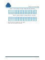
1
RTMU
Control & Monitor Relay
User Manual
RTMU Control & Monitor Relay
Contents
1
Description of Operation ...................................................................................... 4
1.1
1.2
1.2.1
Tap Position Measurement .................................................................................... 4
1.2.2
Voltage Measurement ............................................................................................ 4
1.2.3
Output Contacts ..................................................................................................... 4
1.3
Design ..................................................................................................................... 4
1.3.1
Tap Position Indication .......................................................................................... 5
1.3.2
Voltage Monitor ..................................................................................................... 5
1.4
Description of Features ........................................................................................... 7
1.4.1
Control Switches.................................................................................................... 7
1.4.2
In Progress Indication ............................................................................................ 8
1.4.3
Tap Position Indication .......................................................................................... 8
1.4.4
Runaway Prevention .............................................................................................. 8
1.4.5
System Voltage Levels ........................................................................................ 10
1.5
User Interface........................................................................................................ 11
1.5.1
General ............................................................................................................... 11
1.5.2
Indications ........................................................................................................... 12
1.5.3
Controls ............................................................................................................... 13
1.6
Settings ................................................................................................................. 13
1.6.1
Site Arrangement ................................................................................................. 13
1.6.2
Network Operation, Voltage Levels ...................................................................... 13
1.7
2
Introduction ............................................................................................................. 4
Tap Change Monitor Functions ............................................................................... 4
Hardware .............................................................................................................. 13
1.7.1
Relay Construction .............................................................................................. 13
1.7.2
Terminal Blocks ................................................................................................... 13
Performance Specification................................................................................. 14
2.1
2.2
2.3
2.4
2.5
2.6
2.7
2.8
Introduction ........................................................................................................... 14
Power Supply ........................................................................................................ 14
Voltage Transformer.............................................................................................. 14
Tap Position .......................................................................................................... 14
Settings Range...................................................................................................... 14
Accuracy ............................................................................................................... 15
Output Contact Ratings ......................................................................................... 15
Environmental Withstand ...................................................................................... 15
3
Applications ....................................................................................................... 16
4
Installation ......................................................................................................... 20
4.1
4.2
4.3
4.4
5
v2.0
Unpacking, Storage and Handling ......................................................................... 20
Recommended Mounting Positions ....................................................................... 20
Relay Dimensions ................................................................................................. 20
Connections .......................................................................................................... 20
Commissioning .................................................................................................. 22
Page 2 of 31
RTMU Control & Monitor Relay
5.1
5.2
5.3
5.4
Introduction ........................................................................................................... 22
Inspection.............................................................................................................. 22
Test Supplies ........................................................................................................ 22
Tests ..................................................................................................................... 22
5.4.1
5.5
6
Insulation ............................................................................................................. 22
RTMU Relays ........................................................................................................ 22
5.5.1
Control Module .................................................................................................... 22
5.5.2
Tap Position Indicator. ......................................................................................... 23
5.5.3
Voltage Monitor ................................................................................................... 25
Maintenance ...................................................................................................... 27
6.1
6.2
6.2.1
Voltage Monitor Levels ........................................................................................ 27
6.2.2
Difference ............................................................................................................ 27
6.2.3
Runaway Prevention ............................................................................................ 27
6.2.4
Alarms ................................................................................................................. 28
6.3
v2.0
Introduction ........................................................................................................... 27
Tests ..................................................................................................................... 27
Completion ............................................................................................................ 28
Page 3 of 31
RTMU Control & Monitor Relay
1
Description of Operation
1.1
Introduction
The RTMU control and monitor relays are designed for use with SuperTAPP type RVM relays,
SuperTAPP n+ Voltage control relays, or as stand-alone monitor devices for existing or new voltage
control systems. When used in conjunction with RVM or SuperTAPP n+ voltage control relays, a
comprehensive, self-contained tap change control system is provided in an extremely cost effective
manner, such that minimum external wiring is required to complete the installation.
Two relays are available:
•
RTMU/1m Control and monitor unit with Resistor tap position input (BCD Optional)
•
RTMU/2m Control and monitor unit with return to centre off Auto/Manual position and resistor
or BCD tap position input.
1.2
Tap Change Monitor Functions
1.2.1
Tap Position Measurement
A tap position indicator with mechanical runaway prevention logic monitors each tap change operation
and checks that a genuine tap change signal has been initiated.
1.2.2
Voltage Measurement
A voltage monitor checks the output voltage of the power transformer and inhibits tap change
operations which would cause the voltage to go above or below pre-set maximum and minimum
voltage levels.
1.2.3
Output Contacts
Tap change lockout
Relay output contacts are provided such that the tap change motor supply circuit can be disconnected
in the event of a runaway situation.
Voltage monitor
Normally closed contacts are provided on each of the high and low monitors which inhibit further tap
change operations in the wrong direction when connected into the raise and lower contactor initiation
circuits.
Alarm
An output relay with a normally open contact is provided for external alarm if a tap change runaway or
voltage abnormality is detected after a time delay.
1.3
Design
For general use the RTMU/1m relay is available to meet the requirements of standard tap change
schemes. The RTMU/2m relay has modified Auto/Manual with return to 'centre off' position control
switch for use with some systems.
v2.0
Page 4 of 31
RTMU Control & Monitor Relay
Figure 1 and Figure 2 are block diagrams of the relay functional structure.
1.3.1
Tap Position Indication
The tap position is indicated by a liquid crystal display (LCD) driven via a filtered input circuit from a
resistor type sender unit. A digital input circuit is additionally available as standard on the RTMU/2m
or as an option on the RTMU/1m. This can be either binary coded decimal (BCD) or true binary. If
used with a resistor sender unit the tap position indicator will read the correct tap position regardless
of the number of taps or the resistor values (within the limits set, see specification).
Underlying the tap position indicator is the runaway prevention logic, where detection of raise or lower
signals is used to determine the valid operation of the tap change mechanism. If a tap change
operation takes place without a previous raise or lower tap change initiation signal, a lockout relay is
operated which can be used to disable the tap change motor.
1.3.2
Voltage Monitor
In automatic operation the voltage monitor continuously checks the output voltage of the power
transformer and inhibits tap change operations which would cause the voltage to go above or below
pre-set maximum and minimum voltage levels. If for any reason the maximum or minimum levels are
exceeded, instantaneous indication is provided followed by closing of an output contact after 15
minutes for a remote alarm.
All phases are monitored. Any out of balance inhibits unwanted raise tap change operations, for
example those which could be caused by a blown H.V. voltage transformer fuse.
v2.0
Page 5 of 31
RTMU Control & Monitor Relay
Figure 1 – RTMU/1m block diagram
v2.0
Page 6 of 31
RTMU Control & Monitor Relay
Figure 2 – RTMU/2m block diagram
1.4
Description of Features
1.4.1
Control Switches
The relay includes Auto/Manual and Raise/Lower control switches; these switches are internally
connected for inclusion into an overall tap change control scheme, see Figure 1. Figure 2 shows the
internal arrangement for an Auto/Manual selector switch with a return to centre off position. This is
used in some applications to allow auto/manual selection from multiple sources.
v2.0
Page 7 of 31
RTMU Control & Monitor Relay
1.4.2
In Progress Indication
An indicator shows that a tap change is in progress and, unlike a normal indication which is driven
from an auxiliary switch, is triggered by:
•
Detection of a 'raise' or 'lower' control signal
•
A genuine tap position change
•
An 'In Progress' auxiliary tap change mechanism switch
Given a control 'raise' or 'lower' the IP indication will stay on, and an incomplete alarm sent if a tap
position change is not detected.
1.4.3
Tap Position Indication
The tap position indicator (TPI) is a digital indicator which can be driven by practically any sender unit.
Runaway prevention logic offers a high degree of protection against inadvertent tap change
operations.
Information given by the display is shown in Figure 3.
Figure 3 – Tap position indication display
On start-up the processor checks internal functions and drives all segments on the display. The
calculated tap position is then indicated, this reading is dependent on the set up switch (see
commissioning notes) and the tap position sender unit output. If, for any reason the tap position
changes, other than during a controlled tap changing operation, the display will mark the tap position
as suspect. If the calculated tap position changes to read tap 1 (resistor sender unit) or tap 0 (BCD
sender unit), the display will read 'help' and an alarm will be sent.
1.4.4
Runaway Prevention
A Runaway can be defined as a condition where the tap changer is operating in a direction which will
either cause the voltage to move further away from the desired value and/or the circulating current to
increase. There are two main causes:
•
Wiring fault or mechanism failure on the transformer causing unwanted tap changes
•
Relay fault causing repeated raise or lower pulses.
Mechanism Faults
If the mechanism is working correctly every tap change operation will be preceded by a new control
signal. If the mechanism starts to run away a tap change will take place without a further initiating
signal. The Runaway Prevention Unit monitors every change in tap position via signals from the tap
position indicator. If, after an initial tap change, any operations are detected without a further genuine
control signal being sent, a lockout is initiated which can be arranged to disconnect supply to the tap
change drive motor. This applies to manual or automatically initiated electrical operations. Some tap
changers have transfer positions where more than one operation is required to complete a tap
change. In this event the unit can be configured to allow for transfer tapping.
v2.0
Page 8 of 31
RTMU Control & Monitor Relay
Lockout Logic
For a tap change to be correct, the following sequence must take place, as shown for a normal
operation, Figure 4.
:
1. A control signal must be sent to initiate the process.
2. The tap position must change to a new position.
3. The tap change mechanism must stop completely.
On most schemes an 'In Progress' (IP) auxiliary switch is also closed and used to indicate the
operation of the mechanism, the operation of this contact is also shown. To confirm correct operation
of the runaway logic a definite break between successive tap change operations must be detected as
indicated by the reclaim time in Figure 4 to Figure 6.
Figure 4 – Normal operation
For an incorrect tap change, Figure 5, where the mechanism over-runs, or continues to operate, a
new control signal AND/OR IP is detected before the internally generated reclaim time has expired.
The tap change has satisfied 3 above, and a further tap position change will result in a lockout.
v2.0
Page 9 of 31
RTMU Control & Monitor Relay
Figure 5 – Runaway condition
The runaway prevention unit also protects against a runaway situation during push button operation.
Unwanted operations in manual control are prevented by avoiding further operations until the "in
Progress" LED is extinguished. Where apparent changes in tap position are seen, i.e. a faulty/high
resistance sender unit contact, Figure 6, shows how a lockout will not be initiated. In this case no
control signals are detected and, as the mechanism is in a quiescent state a runaway is unlikely to
occur. The LCD display will mark the visible indication of tap position as suspect in this case until a
further control signal initiates a tap change operation.
Figure 6 – Poor contacts – no lockouts
If, because of the particular design of a tap change scheme, 'raise', 'lower' and 'in progress' signals
are not available during the tap change cycle, monitor relays using tap position logic only for runaway
prevention can be supplied, to specific order.
1.4.5
System Voltage Levels
The voltage monitor checks the maximum and minimum levels of system voltage, each level being
dependent upon the settings applied to the voltage control relay. For security the voltage monitor
settings and measurement circuits are not included in the accompanying voltage control relay
(SuperTAPP n+ or RVM). The voltage level is monitored for valid upper and lower limits. The limits
beyond which the system voltage should not persist is set by the voltage control relay settings, i.e.
Basic, LDC and V Offset. Active blocking of Raise or Lower control signals takes place automatically
2% within the upper and lower alarm limits.
v2.0
Page 10 of 31
RTMU Control & Monitor Relay
To clarify the action of the voltage monitor refer to Figure 7. When the system voltage moves to point
'A' a raise blocking contact is opened. As the voltage is now within 2% of the normal upper limit the
voltage control relay should not correctly request a raise operation.
Figure 7 – Voltage monitor blocking and alarm
As the system voltage increases further to 'B' the alarm timer is initiated, the voltage control relay, if
operating correctly, will initiate a lower tap change operation and the system voltage will be changed
to 'C' before the alarm time-out is exceeded and the timer is reset. As the system voltage reduces to
'D' the raise blocking contacts are released, allowing raise tap change operations to take place if
needed. The reverse action takes place if the system voltage drifts in the lower direction.
Unlike the voltage control relay, which uses two of the three available voltage transformer (VT) phase
voltages for measurement purposes, the voltage monitor uses all phases, and detects any voltage
difference between phase voltages as a check against VT HV or LV fuse failure. If a difference is
detected the monitor will inhibit tap change 'raise' operations but allow 'lower' operations.
1.5
User Interface
1.5.1
General
The design of the relay fascia plate is user friendly each function is shown as a set of logical functions
organised to be easily understood. Fascia plate arrangements for the RTMU/1m and RTMU/2m relays
are shown in Figure 8.
v2.0
Page 11 of 31
RTMU Control & Monitor Relay
Figure 8 – RTMU/Xm fascia
1.5.2
Indications
Indications provided are shown in Table 1.
Table 1 – Indications
Function
Colour
Indication
TAP IN PROGRESS
Amber
Operation of the tap changer via the Raise, Lower,
In Progress contact or Tap Position
LOCKOUT (not RTPI/1m)
Red
Invaid tap change operation
HIGH (RTMU)
Red
System voltage is above a maximum level
LOW (RTMU)
Red
System voltage is below a minimum level
ALARM (RTMU)
Red
System voltage has remained at an abnormal level
(not zero) for more than 15 minutes
TAP POSITION
LCD
The current tap position
v2.0
Page 12 of 31
RTMU Control & Monitor Relay
1.5.3
Controls
Control (Manual/Auto)
A control switch is provided which allows the tap change control system to be operated under hand
control or under the control of a voltage control relay.
5.3.2. Manual (Raise/Lower)
When the control switch is set to manual, this switch, with a centre off position, allows manual
electrical control of the tap change mechanism.
5.3.3. High
A high setting adjustment is provided which allows the high limit of normal voltage to be set.
5.3.4. Low
A low setting adjustment is provided which allows the low limit of normal voltage to be set.
1.6
Settings
1.6.1
Site Arrangement
It is necessary for the tap position indicator to be configured for the particular tap change mechanism.
The relays can be configured on site for the particular tap changer, for further information see the
commissioning section of this document.
1.6.2
Network Operation, Voltage Levels
The operational settings of the voltage control system determine the normal range of voltage that will
be expected at a site, the high and low voltage monitor settings should be set in accordance with
these levels.
Depending on the type of VT used the 3 phase monitor sensitivity will be set for the on-site condition.
Where a 3 phase VT is installed a setting of 5% is normally selected unless the voltages are severely
unbalanced, where a
10% selection is usually sufficient. If a single phase VT is used for voltage sensing the voltage
difference should be disabled.
1.7
Hardware
1.7.1
Relay Construction
The relay is housed in a mild steel case finished in oven-baked powder coating. The relay is mounted
within the case on a semi-withdrawable chassis which carries the complete assembly including the
rear connector strips.
1.7.2
Terminal Blocks
At the rear of the relay terminal strips allow for all connections to the relay, see also Figures 1 and 2
for connections.
v2.0
Page 13 of 31
RTMU Control & Monitor Relay
2
Performance Specification
2.1
Introduction
Performance to IEC255-3
2.2
Power Supply
Auxiliary Supply:
110V or 220Va.c.
Range:
45%-140%
Burden:
3 VA
2.3
Voltage Transformer
Rated voltage:
60V to 140V true rms (default 110V rms)
Burden:
3 VA
2.4
Tap Position
Resistor Sender:
Minimum value of each resistor 10 ohms
Maximum value of each resistor 470 ohms
Recommended value 100 ohm 1 Watt 1%
BCD Sender:
Bit weighting 1,2,4,8,10,20
Binary Bit weighting 1,2,4,8,16,32
2.5
Settings Range
High Voltage limit:
95% - 115% continuously adjustable
Low Voltage limit:
90% - 105% continuously adjustable
Voltage difference:
Disable, 5% or 10%
Number of taps:
11 to 41 in Resistor mode or 11 to 39 in BCD
mode
Transfer tap position:
2 each side of mid -position (or any arrangement
by request)
Alarm:
15 min.
v2.0
Page 14 of 31
RTMU Control & Monitor Relay
2.6
Accuracy
High Voltage limit:
±1%
Low Voltage limit:
±1%
Voltage Difference:
±10% at 5% setting, ±15% at 10% setting,
Alarm:
15 min ±10 sec.
2.7
Output Contact Ratings
Lockout, V high and V low:
10A 240V AC maximum
450mA 110V DC maximum
Alarm:
5A 240V AC maximum
450mA 110V DC maximum
2.8
Environmental Withstand
Temperature
Operating range:
-10°C to +50°C
Storage range:
-25°C to +70°C
Transient Overvoltage
Between all terminals and earth or
between any two terminals:
5kV 1.2/50µs
High Frequency Disturbance
2.5kV Common (longitudinal) mode:
≤ 3% deviation
1kV Series (transverse) mode:
≤ 3% deviation
Electrostatic Discharge
8kV contact discharge:
no maloperation
Fast Transient
4kV 5/50µs 2.5kV repetitive:
≤ 3% deviation
Mechanical Classification
Durability:
v2.0
6
in excess of 10 operations
Page 15 of 31
RTMU Control & Monitor Relay
3
Applications
Figure 9 to Figure 12 show some application drawings for a voltage control scheme incorporating the
RTMU relay.
Figure 9 – Typical tap change motor circuit
v2.0
Page 16 of 31
RTMU Control & Monitor Relay
Figure 10 – VT and CT connections
v2.0
Page 17 of 31
RTMU Control & Monitor Relay
Figure 11 – Typical tap change control circuit
v2.0
Page 18 of 31
RTMU Control & Monitor Relay
Figure 12 – Tap position indicator connections
v2.0
Page 19 of 31
RTMU Control & Monitor Relay
4
Installation
4.1
Unpacking, Storage and Handling
On receipt unpack the relay and inspect for any obvious damage. It is not normally necessary to
remove the relay from its wrapping unless some damage is suspected or if it is required for immediate
use. If damage has been sustained a claim should immediately be made against the carrier, also
inform Fundamentals Ltd. When not immediately required, return the relay to its carton and store in a
clean, dry, place. Equipment should be isolated from auxiliary supplies prior to commencing any work
on an installation.
4.2
Recommended Mounting Positions
The use of the SuperTAPP n+ relay and RTMU monitor relay allows a complete voltage control
system to be contained in a 19 inch rack at 4U height. The mounting of two relay systems in a cubicle
allows two transformers to be operated in parallel, providing an economic use of space. The relays
are normally mounted flush to the panel front using either a sub-rack in a rack cubicle or 4mm screws
when mounted directly in custom slots. The diagrams at the end of this section give details of case
size and fixing dimensions.
4.3
Relay Dimensions
Details of the key relay dimensions are shown in Figure 13.
1. Standard 19" rack
2. 4mm screws
4.4
Connections
All connections are made using the supplied 4BA pan head screws; each connector point allows a
maximum crimp terminal width of 7.5mm.
v2.0
Page 20 of 31
RTMU Control & Monitor Relay
Figure 13 – Relay Type RTMU/1m & RTMU/2m
v2.0
Page 21 of 31
RTMU Control & Monitor Relay
5
Commissioning
5.1
Introduction
The SuperTAPP voltage control system undergoes full calibration and functional checks during
manufacture. Some on site checks are necessary to confirm correct operation of the relay and the
external connections prior to operation. Commissioning of equipment should only be carried out by
skilled personnel trained in relay operation and capable of observing all the necessary safety
precautions and regulations appropriate to this equipment and also the associated primary plant.
Ensure that all test equipment and leads have been correctly maintained and are in good condition.
Full operational checks should be carried out with the transformer(s) on load using system voltage
and currents to ensure that the VT/CT relationships, both phase angle and magnitude, are correct.
5.2
Inspection
A visual check should be made of all wiring to confirm correct connections. Pre-testing of the tap
change mechanism is assumed for the purposes of this document.
5.3
Test Supplies
A good quality rms sensing voltmeter and a variable output transformer can be used to confirm
operation of the relay.
5.4
Tests
5.4.1
Insulation
It is an advantage to have an insulation resistance testing schedule. It is usual to measure and record
the insulation resistance section by section, each section being defined by its supply sub-fuse.
Insulation resistance can be measured before the supply fuses and links are inserted by testing from
the load side of the fuse and link bases. These tests should be carried out with all the wiring in a
section shorted together, therefore temporary connections will be needed to link-in any wiring
separated by normally open contacts etc. While tests are being carried out on one section all other
sections should be earthed using temporary connections.
Where particular circuits are normally earthed, e.g. CT secondary circuits, one earth link at a time
should be removed to permit the testing of its associated circuits. Replacement of the earthing links
and the removal of all temporary connections, including temporary earth connections, should be
confirmed by an entry in the insulation resistance testing schedule. The insulation resistance values
that should be considered to be acceptable depends upon the amount of wiring involved. Where a
considerable amount of multi-core cabling is included, a reading of 2.5 to 3.0 megohms is reasonable,
but for shorter lengths of panel wiring, higher readings should be expected. A reading 1.0 megohm or
less should not be considered satisfactory and should be investigated.
5.5
RTMU Relays
5.5.1
Control Module
The module may be panel mounted or rack mounted as required. A check should be made to ensure
that the tap changer functions correctly for both automatic and manual operations.
v2.0
Page 22 of 31
RTMU Control & Monitor Relay
5.5.2
Tap Position Indicator
Three connections are required to a remote resistance type sender unit. Please note that on some
older types of control circuit the 110V AC supply may have been connected directly across the remote
sender unit and in this case it must be removed before connecting the new unit.
For older units it is recommended that the opportunity is taken to clean and lubricate the contacts of
the remote sender unit particularly if the Runaway Prevention feature is to be used.
Conditioning
The site conditioning switches are located at the bottom right of the RTMU fascia plate, (see
Description of Operation section of this document) and are arranged as shown in Figure 14.
Figure 14 – Site Conditioning Switch
Maximum Tap Position
For calculation of the actual tap position SW1 to SW4 must be set for the maximum number of taps
for the particular tap changer. If the tap changer has an even number of taps with a resistor type
sender unit, an extra resistor should be inserted at the top of the resistor chain and the switch
selected for Max.+1.
Table 2 – Switch settings for maximum tap position
Number of Taps
SW1
SW2
SW3
SW4
11
|
|
|
|
|
|
|
|
|
|
|
|
|
|
|
|
|
|
|
|
|
|
|
|
|
|
|
|
|
|
|
|
13
15
17
19
21
23
25
27
29
31
33
35
37
39
41
v2.0
SW5
SW6
SW7
SW8
Page 23 of 31
RTMU Control & Monitor Relay
Type of Sender Unit
Set SW5 according to the type of sender unit, resistor or binary coded decimal (BCD).
Table 3 – Switch settings for type of sender unit
SW1
SW2
SW3
SW4
SW5
Resistor
|
BCD
SW6
SW7
SW8
Type of Tap change
Some tap changers have transitional tap positions where more than one operation is carried out for a
single raise or lower control signal. Furthermore, some tap changers have these transfer positions
indicated as, say, 8A, 8B & 8C where positions 8B and 8C are not used for voltage change. For the
same effect another tap changer may have positions 8, 9 &10 where 8 & 10 are not used for voltage
change.
To clarify the types of transfer tap changers, those with suffix letters A B C etc. are termed 'suffix'
type, those with discrete numbers, e.g. 8 9 10 are termed 'discrete' type. Where the relay is used with
a 'suffix' type tap changer the sender unit (resistor or BCD) should be arranged to send the same
signal for each of the suffix positions and SW6 should be set to Off (normal). Resistor types should
have the appropriate resistors on the sender unit shorted out, see Figure 15.
Figure 15 – Shorting out sender unit resistors
Where the relay is used with a tap change having "discrete" transfer positions, this switch should be
set to On (transfer). The relay is normally supplied to allow for two "discrete" transfer tap change
operations per control signal. Replacement controller IC's are available on request for nonstandard
schemes including BCD with an even number of taps and Discrete types with more than 2
consecutive transfer operations.
Table 4 – Switch settings for type of tap change
SW1
SW2
SW3
SW4
SW5
SW6
Transfer
|
Normal
SW7
SW8
TPI Operation
Operate the tap changer to the highest tap position and confirm correct indications. If the transformer
cannot be taken out of service the top tap position can conveniently be simulated by temporarily
disconnecting the wire going to terminal 26 and then shorting 26 to 27.
After replacing any temporary connections, check the indication through the full range of the tapchanger (if possible).
v2.0
Page 24 of 31
RTMU Control & Monitor Relay
In the unlikely event that satisfactory calibration cannot be obtained, the sender unit resistors should
be replaced. Suitable resistors are 100ohm, 1Watt, 1% tolerance metal film resistors.
Checking for Normal Operation
Operate the tap changer in the raise direction and observe the normal correct operation of tap
changer.
Immediately the "in Progress" LED goes off, operate the tap change once more in the same direction
and again observe correct operation. Repeat for the lower direction.
Induced voltages on quiescent "raise", "lower" and "In Progress" wiring can, if excessive, power the In
Progress LED. The application of a 0.22µF mains suppression capacitor between the relevant input
terminals and "neutral" of the RTMU relay will attenuate these false signals
Checking for Lockout
Carry out a raise operation but this time simulate a potential runaway condition by permanently
energising the "raise" contactor or, alternatively, by repeated operation of the tap change control
switch. The runaway prevention Unit should lock out soon after the first complete tap change
operation, depending on the tap change operating time. Repeat for the lower direction.
For very fast tap change mechanisms more than one tap change operation may occur before the
lockout operates. In this case great care should be exercised if the test is carried out with the
transformer on load.
5.5.3
Voltage Monitor
Determination of high and low alarm settings is shown below.
The High setting is calculated using the formula:
(Basic Voltage %)+ (Full Load LDC Boost%) + (Upper Bandwidth %) + (1/2% for safety)
Similarly the low setting formula is:
(Basic Voltage %) - (6% Load Shed) - (Lower Bandwidth %) - (1/2% for safety)
e.g. With a 100% basic setting, a 5% LDC setting and a plus/minus 1.5% band width setting the "high"
setting would be 107% and the "low" setting 92%. The raise and lower "inhibit" relays are
automatically set to operate 2% before the "Alarm" settings thus preventing the tap changer from
operating in a direction which would cause the voltage to go outside the alarm limits.
Checking for Correct Operation
The voltage monitor can be checked using a variable test supply and an accurate voltmeter. The
voltage difference feature will need to be disabled. The "High" and "Low" LED's will indicate when the
alarm settings are reached. During this test the proper functioning of the inhibit circuits and 15 minute
alarm can also be checked.
Voltage Difference
SW7 should be set for phase voltage difference detection.
SW8 determines the voltage difference sensitivity.
The correct operation of the voltage difference detector can be confirmed by removal of the VT fuse
which does not supply the accompanying voltage control relay (SuperTAPP n+ or RVM). In this case
the voltage monitor will block any raise control signals.
v2.0
Page 25 of 31
RTMU Control & Monitor Relay
Table 5 – Switch settings for phase voltage difference detection
SW1
SW2
SW3
SW4
SW5
SW6
SW7
Disable
|
Enable
SW8
Table 6 – Switch settings for voltage difference sensitivity
SW1
SW2
SW3
SW4
SW6
SW7
SW8
10%
|
5%
•
Set basic control to force RVM relay to raise voltage
•
Confirm 'raise' control signals are blocked
v2.0
SW5
Page 26 of 31
RTMU Control & Monitor Relay
6
Maintenance
6.1
Introduction
Voltage control systems are continually operative when in service. Any deviations in accuracy and
control will directly affect the customers connected to the controlled power system. The SuperTAPP
n+ voltage control system has been designed with reliable voltage control circuitry with continuous
separate monitoring of the resultant system voltage, including the voltage transformer. Minimal
checks can be carried out on the relay during operation to confirm correct operation.
Maintenance of equipment should be carried out only by skilled personnel trained in relay operation
and capable of observing all the necessary safety precautions and regulations appropriate to this
equipment and also the associated primary plant. Ensure that all test equipment and leads have been
correctly maintained and are in good condition. No specialist test equipment is required.
6.2
Tests
As the tests can be best carried out with the transformers on load, care should be taken to ensure that
no operation of the tap changers can take place when settings are changed. As settings will be
changed for testing purposes, the operational levels should be noted prior to testing.
6.2.1
Voltage Monitor Levels
Use a good quality rms measuring voltmeter to measure the incoming voltage transformer level. Move
High monitor level control until High Indication, move High monitor level control until Low Indication.
Check that the two settings are within 1/2% of the measured voltage.
6.2.2
Difference
The correct operation of the voltage difference detector can be confirmed by removal of the VT fuse
which does not supply the voltage control relay. In this case the voltage monitor will block any raise
control signals.
•
Set basic control to force the voltage control relay to initiate a raise operation
•
Confirm 'raise' control signals are blocked
6.2.3
Runaway Prevention
Checking for Normal Operation
Operate the tap changer in the raise direction and observe the normal correct operation of tap
changer.
Immediately the "in Progress" LED goes off, operate the tap change once more in the same direction
and again observe correct operation. Repeat for the lower direction.
Checking for Lockout
Carry out a raise operation but this time simulate a potential runaway condition by permanently
energising the "raise" or "lower" contacts or, alternatively, repeated operation of the tap change
control switch. The Runaway Prevention Unit should lock out soon after the first complete tap change
operation, depending upon the tap change operating time. Repeat for the lower direction.
v2.0
Page 27 of 31
RTMU Control & Monitor Relay
For very fast tap change mechanisms more than one tap change operation may occur before the
lockout operates. In this case great care should be exercised if the test is carried out with the
transformer on load.
6.2.4
Alarms
Operate a tap changer to lockout and check operation of alarm contacts after 15 minutes.
6.3
Completion
On completion of tests all settings can be returned to normal.
v2.0
Page 28 of 31
RTMU Control & Monitor Relay
Notes
RTMU Control & Monitor Relay
RTMU Control & Monitor Relay