1
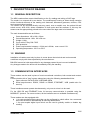
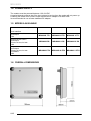
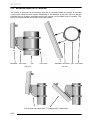
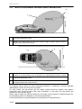
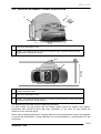
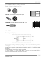
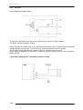
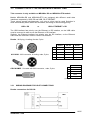
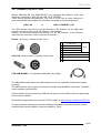
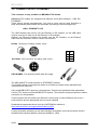
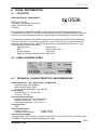
MRU 688X
USER MANUAL
REFERENCE: UM-MRU688X-1.0-EN
BALOGH SA
BALOGH TAG
189 Rue d’Aubervilliers - CP 97 - 75886 Paris
Cedex 18 - France
Téléphone: 33 (0)1 44 65 65 00
Fax: 33 (0)1 44 65 65 10
Web: http://www.balogh-rfid.com
3637 Old US-23
Brighton, Michigan MI 48114, USA
Tel: USA (800) 252-RFID (7343)
(810) 360-0182
Canada (800) 258-RFID (7343)
Fax: (810) 360-0237
MRU 688X
Page intentionally left blank
2/25
UM-MRU688x-1.0-EN
MRU 688X
PREFACE
Purpose of this manual
This manual presents the BALOGH UHF readers MRU688x models.
It describes how to install and how to use them.
Further information pertaining to the data interfaces described in this manual can be found in
the Interface Manual (reference IM-MRU-II-L)
Document naming conventions
The coding used for a manual name is:
UM- <device name>-x.y-L
in which:
UM signifies User Manual
x.y refers to the issue or version number
L refers to the language of the manual
Document status sheet
Version Date
Description of changes
1.0
14/07/2014 Creation (translation of French version 1.0)
Note
The contents of this manual are subject to changes without notice.
BALOGH cannot be held responsible for the consequences of any error, omission, or incorrect
interpretation of the information provided
3/25
UM-MRU688x-1.0-EN
MRU 688X
CONTENTS
1
DESCRIPTION OF READER ............................................................ 5
1.1
1.2
1.3
1.4
1.5
1.6
2
GENERAL DESCRIPTION .............................................................................5
WARNING.......................................................................................................5
COMMUNICATION INTERFACES .................................................................5
POWER SUPPLY ...........................................................................................6
MODELS AVAILABLE ....................................................................................6
OVERALL DIMENSIONS ................................................................................6
INSTALLING THE MRU READER .................................................... 7
2.1
2.2
2.3
3
MOUNTING ON A POLE ................................................................................7
MOUNTING ON A WALL ................................................................................9
POSITIONING OF READER.........................................................................11
ELECTRICAL CONNECTIONS ....................................................... 14
3.1
3.2
3.3
3.4
3.5
4
CONNECTOR N°1 : POWER SUPPLY & TTL INTERFACE ........................15
CONNECTOR N°2 : INPUT / OUTPUT ........................................................17
CONNECTOR N°3 : ASYNCHRONOUS SERIAL LINK ................................19
CONNECTOR N°4 : USB..............................................................................21
CONNECTOR N°5 : ETHERNET ..................................................................22
SERVICE OPERATION ................................................................... 23
4.1
4.2
4.3
5
OPERATION OF THE INDICATOR LIGHT...................................................23
READER SETTINGS ....................................................................................23
FREQUENCY SETTINGS.............................................................................23
MAINTENANCE ............................................................................... 24
5.1
5.2
5.3
6
PERIODIC MAINTENANCE ..........................................................................24
REPLACEMENT ...........................................................................................24
RECYCLING .................................................................................................24
LEGAL INFORMATION ................................................................... 25
6.1
6.2
6.3
CE NOTICE ..................................................................................................25
LABEL ON REAR PANEL .............................................................................25
TECHNICAL CHARACTERISTICS AND DIMENSIONS ...............................25
4/25
UM-MRU688x-1.0-EN
MRU 688X
1 DESCRIPTION OF READER
1.1 GENERAL DESCRIPTION
The MRU readers allow remote identification on the fly, reading and writing of UHF tags
The reader is a compact all-in-one device. The weatherproof housing of sober design contains
all the functional elements of the reading unit: Antennas, Microwave generator, receiver, CPU
and communication interface.
The reader can be mounted directly onto any panel, even a metallic one. An optional tilt and
swivel mount, ACS 8310, allows installation on both poles and flat surfaces. In this way the
antenna can be appropriately pointed to the zone where the tags need to be identified.
The main characteristics are as follows:
Case dimensions: 186 x 186 x 33mm
Overall dimensions: 186 x 186 x 58 mm
Weight: 1,8Kg
Cover colour: Grey RAL 7035
IP65 protection
Power requirements: between +12Vdc and +24Vdc, max current 1.5A.
Operating temperature: -20°C to +50°C
1.2 WARNING
Installation of readers must only be done in zones where the technical and environmental
conditions comply with those specified by the manufacturer.
BALOGH cannot be held responsible for any damages caused by an incorrect installation.
Any changes made to the device will immediately nullify the warranty.
1.3 COMMUNICATION INTERFACES
These readers can be used in place of most conventional controllers, both contact and contactless.
Communication with a "host" system takes place using the following standardised links:
Open-collector: DATA/CLOCK, WIEGAND 26bits
Serial asynchronous: RS232, RS422 or RS485, ETHERNET, USB (usable also for
service)
These interfaces cannot operate simultaneously, only one at a time is to be used.
For the USB, RS and ETHERNET links, full two-way communication is possible using the
MODBUS™ protocol. For some versions, all the interfaces are not available simultaneously.
These readers are also equipped with:
1 An opto-coupled digital output that can be configured to switch either via a command
sent from the host or automatically at each tag identification.
1 An opto-coupled digital input which can be used to globally enable or disable tag
reading.
5/25
UM-MRU688x-1.0-EN
MRU 688X
1.4 POWER SUPPLY
The readers must be powered between 12 & 24 VDC.
A special detector ensures that if the input voltage is too low then the reader will not power up.
Powering the reader from a mains outlet requires an AC adaptor of at least 18W.
Its recommended to use a linear stabilized AC adaptor
1.5 MODELS AVAILABLE
Antenna polarization
Circular
Horizontal
Vertical
Wiegand 26 bits ; ISO-2
Input/Output
USB
MRU6882 TTL
MRU6883 H TTL
MRU6883 V TTL
Wiegand 26 bits ;ISO-2
Input/Output
RS 232, RS 422, RS 485
USB
MRU6882 RS
MRU6883 H RS
MRU6883 V RS
Wiegand 26 bits ; ISO-2
Input/Output
RS 232, RS 422, RS 485
ETHERNET
USB
MRU6882 ETH
Host Interface
MRU6883 H ETH MRU6883 V ETH
1.6 OVERALL DIMENSIONS
6/25
UM-MRU688x-1.0-EN
MRU 688X
2 INSTALLING THE MRU READER
At the rear of the reader are two mounting brackets.
These brackets have self-clinching nuts size M6 allowing mounting on any support structure
(e.g. support angles with screws)
These brackets also have oblong holes allowing plastic or metallic collars to pass through.
A mounting kit ACS 8310 allowing easy installation of the reader is available as an accessory.
This kit contains:
a tilt bracket which allows adjusting the tilt angle
a wall-mounting support which allows adjustment of horizontal rotation
metallic hose clamps Ø30mm for attaching the tilt mount onto the support structure
mounting screws for attaching the reader onto the tilt bracket
All the pieces are made of stainless steel.
2.1 MOUNTING ON A POLE
2.1.1
DIRECT MOUNTING
The reader can be mounted directly onto a pole by with a hose clamp that passes through the
openings in the brackets. This type of mount only allows horizontal rotation:
MRU688x
pole
side view
hose clamp
MRU688x
pole
hose clamp
top view
7/25
UM-MRU688x-1.0-EN
MRU 688X
2.1.2
MOUNTING USING THE TILT BRACKET
The reader is mounted onto the bracket using the 4 screws provided; the bracket is mounted
onto the pole using the hose clamps. Depending on the diameter of the pole, the hose clamps
provided may be suitable, otherwise larger hose clamps (not provided) may be needed. This
type of mount allows both horizontal and vertical rotation.
MRU688x
tilt bracket
pole
side view
hose clamp
MRU688x tilt bracket
pole hose clamp
top view
The tilt angle can range from 5° upwards to 45° downwards
8/25
UM-MRU688x-1.0-EN
MRU 688X
2.2 MOUNTING ON A WALL
2.2.1
MOUNTING USING THE TILT BRACKET
The tilt bracket has 4 holes for wall mounting.
screws Ø6mm max
screw type must be chosen to suit wall material
40mm between axes in both directions
MRU688x
tilt bracket
side view
wall
MRU688x
tilt bracket
wall
top view
This type of mount only allows a vertical tilt adjustment from 5° upwards to 45° downwards.
Note: by rotating the bracket 90° (wings are horizontal), horizontal rotation becomes possible.
9/25
UM-MRU688x-1.0-EN
MRU 688X
2.2.2
MOUNTING WITH WALL BRACKET
This bracket, provided in the kit, has 4 mounting holes, whose locations are identical to those of
the tilt bracket. Mounting onto the wall is identical:
The tilt bracket is attached to the wall bracket with the 2 metallic hose clamps provided.
This type of mount allows both horizontal and vertical rotation:
LPR303x
tilt bracket
hose clamp
side view
wall bracket
wallLPR303x
tilt bracket wall bracket
top view
The tilt angle can range from 5° upwards to 45° downwards.
With the reader pointing 45° downwards and mounted on a wall, the maximum horizontal
rotation is roughly 30°.
When there is no tilt, the horizontal rotation can reach 50° on either side.
10/25
UM-MRU688x-1.0-EN
wall
MRU 688X
2.3 POSITIONING OF READER
The directivity of the reader's antenna is a symmetrical 70° x 70°.
Side view
Top view
z
y
70°
y
70°
z
ATTENTION: MRU6883 H & V models dispose of a linear polarisation antenna.
Reader’s polarisation is to be on the same axis than tag installation, H= horizontal,
V= vertical; not respecting this can cause a leak of performance.
Position the reader so that it points to the zone where the tags are likely to be. Maximum
performance is achieved with the line of sight, perpendicular to the face of the reader.
Direction of main radiation is always perpendicular to the face of the reader; excessive tilt angle
between tag and antenna surface is not admissible and preferable to be less than 30 degrees;
at 45 degrees the reflected signal fall down drastically.
With the optional mounting kit ACS 8310, the reader can now be pivoted. The orientation can be
freely adjusted. Pivoting can be either horizontal (side to side) or vertical (up and down).
When positioning the reader, the following recommendations should be followed:
Avoid placing the reader in direct sunlight, where overheating may cause the internal electronics
to reach temperatures above those recommended for normal operation.
If this is not possible then a sun-shield should be mounted.
When two or more readers are situated in the same zone, make sure they are not pointing
towards each other. If necessary, their pointing axes should be slightly redirected.
Do not install a reader close to a source of potential interference in order not to degrade its
performance.
The main sources of interference are:
Devices operating in the same band of frequencies, such as wireless communications
devices,
Fluorescent lighting,
Metal objects such as gratings, fences or heat-reflective vehicle windscreens,
Etc.
11/25
UM-MRU688x-1.0-EN
MRU 688X
2.3.1
INSTALLATION EXAMPLE: INCLINED FRONTAL READING ZONE
2
1
1
Theoretical identification zone
2
Reader. The reader should be positioned so that the angle is between about 30 and 45
degrees down towards the vehicle.
2
1
3
1
The tag, fastened on the windscreen respecting the antenna polarization axis. In that
position, it’s inclined between 30 to 45 degrees for an optimal alignment with the reader.
2
Theoretical identification zone
3
Reader. The reader should be positioned so that the pointing direction is about less than
30 degrees toward the vehicle direction.
The diagram above shows the best reader/tag orientation. In particular it avoids unwanted
identifications in front of but far from the reader.
For best results, the tag surface and the reader surface should be parallel and reader’s
polarization axis should be same than tag’s orientation. In this case, the tag reflects the
maximum of the received signal.
When a tag is fixed to the vehicle windscreen, be aware of the presence of metalized areas (for
heat reflection) which can degrade or prevent tag identification.
Contact BALOGH for recommendations on best practices for tag positioning..
12/25
UM-MRU688x-1.0-EN
MRU 688X
2.3.2
INSTALLATION EXAMPLE: LATERAL IDENTIFICATION
1
2
1
Theoretical identification zone
2
Reader. The reader should be positioned so that the angle is between about 0 and 20
degrees down towards the vehicle.
3
2
1
1
The tag, presented through lateral window in front of the reader and respecting the
antenna polarization axis.
2
Theoretical identification zone
3
Reader. The reader should be positioned so that the pointing direction is about less than
30 degrees toward the vehicle direction.
The diagram above shows the best reader/tag orientation.
For best results, the tag surface and the reader surface should be parallel and reader’s
polarization axis should be same than tag’s orientation. In this case, the tag reflects the
maximum of the received signal.
When a tag is handily presented to a reader, take care on the manipulation, fingers can degrade
or prevent tag identification. Contact BALOGH for recommendations on best practices for tag
positioning.
13/25
UM-MRU688x-1.0-EN
MRU 688X
3 ELECTRICAL CONNECTIONS
All the reader's connectors are found on the rear panel.
All connectors are panel mounts using the M12 standard.
Moulded cable assemblies are available as accessories.
Manual assembly cable connectors with screw-terminals are available as accessories.
ATTENTION: these M12 type connectors are designed for hand-tightening only. Spanners
or pliers must not be used in order not to cause damage.
Connector numbers (rear view of MRU 688x)
1
2
3
4
5
MRU 688x reader is equipped with several data interfaces.
These cannot operate simultaneously; only one at a time can be used.
Models MRU688x-RS and MRU688x-ETH are equipped with different serial data
interfaces, respectively: USB, RS and USB, RS, ETHERNET.
These cannot operate simultaneously; only one at a time can be used. Selection is
done automatically when cables are connected, according to the following priority:
USB > RS
or
USB > ETHERNET > RS
The USB interface has priority over the Ethernet or RS interface, so the USB cable
must be removed in order to use the Ethernet or RS interface.
Similarly, the Ethernet interface has priority over the RS interface, so the Ethernet
cable must be removed in order to use the RS interface.
Further information pertaining to the data interfaces described in this manual can be found in
the MRU 688x Interface Manual (reference IM-MRU-x.y-EN)
14/25
UM-MRU688x-1.0-EN
MRU 688X
3.1 CONNECTOR N°1 : POWER SUPPLY & TTL INTERFACE
This connector has 2 functions: reader power supply and open collector interface for
DATA/CLOCK and WIEGAND
Reader : M12 plug, A-coding, male, 5 pins.
COMMUNICATION
POWER
ISO2
WIEGAND
2
DATA
DATA ―0‖
3
CLOCK
DATA ―1‖
GND
GND
1
4
+DC
0V
5
ACS 8320 : M12 connector, A-coding, female, 5 pins.
Color
CBL M12F5P : 5m cable with M12 connector, female, 5 pins
1
Brown
2
White
3
Blue
4
Black
5
Grey (*)
(*) Grey or Yellow/Green
3.1.1
READER POWER SUPPLY
The reader requires a DC power supply of between 12Vdc and 24Vdc applied between pins 1
and 4 of the connector. The reader electronics are protected against polarity inversion for the
power supply connection
Current drawn is 1.5 A maximum during power-up surge.
Average currents for steady-state operation are given in the following table:
+DC
TTL version
RS-ETH version
12V
530mA
580mA
24V
290mA
340mA
Pay careful attention to the length and gauge of the wire used.
Ohmic losses in the power lead can cause a voltage drop, make sure the input voltage to the
reader is greater than 11.5V.
If the power supply cannot provide sufficient current during the power-up, the front-panel light
will blink red. This is not a fault condition, but an indication that a better-dimensioned power
supply must be used.
15/25
UM-MRU688x-1.0-EN
MRU 688X
3.1.2
OPEN COLLECTOR LINK
Different signals appear on the pins depending on which interface is selected.
ISO2
WIEGAND
2
DATA
DATA ―0‖
3
CLOCK
DATA ―1‖
5
GND
GND
For correct operation, pull-up ( typical resistor value of 1KΩ) are to be connected to a voltage
reference between +5Vdc and +12Vdc.
On most of access control dedicated controllers ―pull-up‖ are already included; so adding
external resistors to the data lines is not mandatory.
For correct operation, it is crucial pull-up voltage value measured at reader connector not to go
under 4.2Vcc nor over 12.5Vcc to prevent any malfunctioning or the destruction of the reader.
Circuit diagram for open-collector output:
Reader connections for DATA-CLOCK:
MRU
Reader connections for WIEGAND :
MRU
16/25
UM-MRU688x-1.0-EN
MRU 688X
3.2 CONNECTOR N°2 : INPUT / OUTPUT
Reader : M12 plug, A-coding, female, 5 pins
ACS 8320 : M12 connector, A-coding, male, 5 pins
1
E+
2
E–
3
4
SV
S+
5
S–
INPUT
OUTPUT
Color
CBL M12M5P : 5m cable with M12 connector, male, 5 pins
1
Brown
2
White
3
Blue
4
Black
5
Grey (*)
(*) Grey or Yellow/Green
3.2.1
INPUT
Circuit diagram for digital input:
This input allows enabling or disabling tag reading, e.g. when a loop vehicle detector provides a
control signal.
An open circuit or a positive voltage less than 4.4V applied to the pin E+ (E- to GND) will disable
tag reading.
A voltage between 7.1V and 24V will enable tag reading.
For correct operation, it is crucial voltage applied to the input must not exceed 24VDC to
prevent any malfunctioning or the destruction of the reader
17/25
UM-MRU688x-1.0-EN
MRU 688X
3.2.2
OUTPUT
Circuit diagram for digital output:
This output is designed to control a 12V or 24V relay, a buzzer or a light indicator.
The drawn current is typically 100mA.
When activated the output turns on the internal transistor and current is drawn from the external
voltage applied on the SV pin. The load is to be connected between pins S+ and SV.
The collector current will induce a voltage of about 1V between these two pins.
When output is disabled, the transistor is turned off and the voltage on pin S+ will be equal to
that on pin SV.
Typical wiring diagram for connecting a buzzer or relay :
MRU
18/25
UM-MRU688x-1.0-EN
MRU 688X
3.3 CONNECTOR N°3 : ASYNCHRONOUS SERIAL LINK
This connector is only available on MRU688x RS and MRU688x ETH models
Models MRU688x-RS and MRU688x-ETH are equipped with different serial data
interfaces, respectively: USB, RS and USB, RS, ETHERNET.
These cannot operate simultaneously; only one at a time can be used. Selection is
done automatically when cables are connected, according to the following priority:
USB > RS
or
USB > ETHERNET > RS
The USB interface has priority over the Ethernet or RS interface, so the USB cable
must be removed in order to use the Ethernet or RS interface.
Similarly, the Ethernet interface has priority over the RS interface, so the Ethernet
cable must be removed in order to use the RS interface.
Reader : M12 plug, A-coding, female, 5 pins
ACS 8320 : M12 connector, A-coding, male, 5 pins
RS-232
RS-422
RS-485
1
TX
TX+
V1+
2
—
TX–
V1–
3
—
RX+
V2+
4
RX
RX–
V2–
5
GND
GND
GND
Color
CBL M12M5P : 5m cable with M12 connector, male, 5 pins
1
Brown
2
White
3
Blue
4
Black
5
Grey (*)
Couleur
(*) Grey or Yellow/Green
3.3.1
WIRING DIAGRAMS FOR HOST CONNECTIONS
Reader connections for RS-232:
1
Marron
2
Blanc
3
Bleu
4
Noir
5
Gris (*)
MRU
19/25
UM-MRU688x-1.0-EN
MRU 688X
Reader connections for RS-422 (full-duplex):
MRU
Reader connections for RS-485 (half-duplex):
MRU
3.3.2
ELECTRICAL CONNECTION
Cables to use for RS-422 and RS-485 links
• In the absence of electrical noise - unshielded twisted pairs.
• In a noisy environment - individually shielded twisted pairs
For short cable lengths, standard cables are satisfactory.
For cables longer than 100 m, high quality cables (low loss, low distributed capacity and
resistance) should be used for all transmission speeds.
Signal inversions
For an RS-232 link, signal polarities and levels are well defined. On both devices RX is
connected to TX and vice-versa.
For an RS-422 or RS-485 link, the signal ―+‖ is normally at a high level at rest and active low,
the reverse is true for the signal "–". This is the case for this reader. If however the differential
signals are generated by a converter from an RS-232 interface, then the ―+‖ line can be at a low
level at rest and active high. In this case, the signals must be inverted.
Connection of GND
For an RS-232 link, the GND of each equipment must be at the same potential. Consequently,
the signal GND (pin 5 on the connector) must be connected to the GND of the host equipment.
For a differential link, this GND connection is not absolutely necessary but often recommended.
20/25
UM-MRU688x-1.0-EN
MRU 688X
3.4 CONNECTOR N°4 : USB
Models MRU688x-RS and MRU688x-ETH are equipped with different serial data
interfaces, respectively: USB, RS and USB, RS, ETHERNET.
These cannot operate simultaneously; only one at a time can be used. Selection is
done automatically when cables are connected, according to the following priority:
USB > RS
or
USB > ETHERNET > RS
The USB interface has priority over the Ethernet or RS interface, so the USB cable
must be removed in order to use the Ethernet or RS interface.
Similarly, the Ethernet interface has priority over the RS interface, so the Ethernet
cable must be removed in order to use the RS interface.
Reader : M12 plug, A-coding, female, 8 pins
ACS 8320 : M12 connector, A-coding, male, 8 pins
1
V USB (+5V)
2
DATA-
3
DATA+
4
GND
5
Do not connect!
6
Do not connect!
7
Do not connect!
8
Do not connect!
USB
COR USB M12M8P : Pre-assembly USB cable 1.8m length
The MRU 688x reader feature an USB interface for service, installation and firmware update
purposes.
The USB interface can be used to configure the reader using MODBUS commands, a freeware
is also available, ask BALOGH.
Communication with the reader over USB is done using a virtual COM port and the appropriate
driver must be installed.
Download the appropriate driver from the FTDI’s website at www.ftdichip.com/Drivers/VCP.htm
Further information pertaining to the data interfaces described in this manual can be found in
the MRU 688x Interface Manual (reference IM-MRU-x.y-EN).
21/25
UM-MRU688x-1.0-EN
MRU 688X
3.5 CONNECTOR N°5 : ETHERNET
This connector is only available on MRU688x ETH models
MRU688x-ETH models are equipped with different serial data interfaces : USB, RS,
ETHERNET.
These cannot operate simultaneously; only one at a time can be used. Selection is
done automatically when cables are connected, according to the following priority:
USB > ETHERNET > RS
The USB interface has priority over the Ethernet or RS interface, so the USB cable
must be removed in order to use the Ethernet or RS interface.
Similarly, the Ethernet interface has priority over the RS interface, so the Ethernet
cable must be removed in order to use the RS interface.
Reader : M12 plug, D-coding, female, 4 pins
ACS 8320 : M12 connector, D-coding, male, 4 pins
1
2
3
4
T+
R+
T–
R–
CBL M12M5P : Pre-assembly RJ45 cable 5m length
The MRU 688x-ETH model features an ETHERNET interface.
This interface allows connecting the reader to an Ethernet network with a standard RJ45
connector at the host end.
Only the MODBUS RTU protocol is implemented. Therefore the application data transmitted
over the TCP socket must be MODBUS RTU frames. The interface component performs neither
conversion nor interpretation.
Communication with the reader over Ethernet is done using a virtual COM port just as for a
serial interface and the appropriate driver must be installed.
Download the appropriate driver from the LANTRONIX’s website at
http://www.lantronix.com/support/downloads/?p=CPR
Further information pertaining to the data interfaces described in this manual can be found in
the MRU 688x Interface Manual (reference IM-MRU-x.y-EN).
22/25
UM-MRU688x-1.0-EN
MRU 688X
4 SERVICE OPERATION
4.1 OPERATION OF THE INDICATOR LIGHT
The indicator light on the reader conveys the reader's behaviour to the user. It is the only visible
part of the system. It is controlled by the embedded reader software. It can also be put under
host control using appropriate MODBUS commands via a serial link.
During the initialization phase, the light is a fixed red. If the initialization is successful, the
indicator light starts to flash green; otherwise it flashes red very slowly.
If after power-on the light flashes quickly, this is usually caused by a power supply problem,
either voltage or current insufficient. This is not a fault condition, but an indication that a betterdimensioned power supply must be used.
During the reading of a tag, the indicator light goes out for one second, and then resumes green
flashing.
4.2 READER SETTINGS
Reader is normally pre-configured at delivery according to element given at order.
It’s possible to modify the reader’ settings by means of specific ModBus commands.
Using ModBus commands can be done anytime at the express condition the reader
communication interface has been correctly configured.
Further information pertaining to the reader configuration described in this manual can be found
in the MRU 688x Interface Manual (reference IM-MRU-x.y-EN).
4.3 FREQUENCY SETTINGS
No frequency adjustment is required for MRU 688x reader
Fully compliant to EN 302208 norm, this reader uses an automatic frequency allocation mode
called « LBT » (=Listen before talk).
In this mode, the reader automatically allocate its frequency settings using one of the available
channel 4, 7, 10 or 13, for complete description refer to the corresponding norm.
This mode allows using the reader at the maximum of its power emission.
23/25
UM-MRU688x-1.0-EN
MRU 688X
5 MAINTENANCE
5.1 PERIODIC MAINTENANCE
The MRU688x reader requires no periodic maintenance
The reader should be regularly cleaned in order to avoid dust and dirt accumulating on the
case.
The reader should be regularly checked for:
cracks in the case
missing mounting screws
screws correctly tightened
connectors correctly locked
5.2 REPLACEMENT
If the MRU688x needs to be replaced, the procedure is as follows:
Turn the knurled ring of the plugs anti-clockwise to unlock the connectors.
Record the reader orientation (azimuth and elevation), then remove the mounting
screws and dismount the unit.
Place the new unit in the same position, insert the mounting screws and tighten
correctly.
Replace connectors and for each turn the knurled ring clockwise until locked.
ATTENTION: these M12 type connectors are designed for hand-tightening only. Spanners
or pliers must not be used in order not to cause damage.
5.3 RECYCLING
All decommissioned readers must be returned to BALOGH SA for appropriate recycling
according to directive D3E.
24/25
UM-MRU688x-1.0-EN
MRU 688X
6 LEGAL INFORMATION
6.1 CE NOTICE
DECLARATION OF CONFORMITY
BALOGH Toulouse
105 Avenue du Général Eisenhower
31023 TOULOUSE cedex 1
FRANCE
0536
This declaration certifies that the MRU reader satisfies the essential requirements of the
European directive R&TTE 1999/5/EC aiming to align the laws of the Member States relating to
the use of the electromagnetic spectrum, electromagnetic compatibility and electrical safety.
This declaration applies to all readers manufactured according to the technical specifications
outlined in Annexe II of the directive. Evaluation of the conformity of the equipment with the
essential requirements article 3 R&TTE has been done in accordance with Annex IV of the
directive and the following standards:
Radio spectrum:
EN 302 208
EMC:
EN 301 489-1 and -3
Electrical safety:
EN 60 950
Exposure to electromagnetic fields: EN 50 364
6.2 LABEL ON REAR PANEL
6.3 TECHNICAL CHARACTERISTICS AND DIMENSIONS
Radio-frequencies : ISO 18000-6 type C et EN302 208
• Frequency band: 865-868MHz
• Built-in antenna gain : 4dBi
• Power emitted: Adjustable up to 2W ERP
Power supply
• Voltage range: 12 - 24 Volts DC
• Current: 1.5A max
Environmental conditions
• Relative humidity: 90% non-condensing
• Storage temperature: -25° to +80° C
• Operating temperature: -20° to +50° C
Protection class
• IP65
External dimensions
• Length: 186mm
• Width: 186mm
• Thickness: 33mm/58mm
• weight: 1,8 kg
Connections available
• Wiegand 26bits, DATA/CLOCK (magnetic stripe ISO 7811-2), RS 232, RS 422, RS485, USB,
ETHERNET (interfaces available depending on model)
25/25
UM-MRU688x-1.0-EN