1
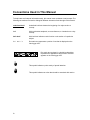
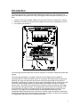
® INTERLOGGER Power KeyCard 8 Channel Programmable Datalogger Version 1.4 InterLogger Power Key Option User's Guide Copyright 1995, 2000 Northwood Data Loggers Limited All Rights Reserved. The information in this document is subject to change without notice. Northwood Data Loggers has made every effort to ensure the accuracy of this manual. However, Northwood Data Loggers makes no warranties with respect to this documentation and disclaims any implied warranties of merchantability and fitness for a particular purpose. Northwood Data Loggers assumes no responsibility for any errors that may appear in this document. Trademarks InterLogger and KeyCard are registered trademarks of Northwood Data Loggers. IBM is a registered trademark of International Business Machines Corporation. Windows and Windows 95 are registered trademarks of Microsoft Corporation. All other product names are copyright and may be trademarks and / or registered trademarks of their respective companies. Document No.IP04-0060600 Printed in Canada Table of Contents Conventions Used In This Manual _________________________________________ iv Support Services_________________________________________________________v Introduction ____________________________________________________________1 Safety _________________________________________________________________2 Hookup / Quick Start _____________________________________________________3 Hookup Wiring _____________________________________________________________ 4 3 Phase 4 Wire (Wye) _____________________________________________________________4 2½ Element______________________________________________________________________5 3 Phase 3 Wire (Delta)_____________________________________________________________5 1 Phase 3 Wire (Edison Circuit) _____________________________________________________6 1 Phase 2 Wire ___________________________________________________________________6 Hookup Diagnostic Warnings__________________________________________________ 7 Power KeyCard Features __________________________________________________9 Front Panel ___________________________________________________________11 Front Panel Controls ____________________________________________________15 ESC _____________________________________________________________________ 15 SETUP ___________________________________________________________________ 16 CHAN _________________________________________________________________________17 RANGE________________________________________________________________________17 RATIO ________________________________________________________________________17 MODE_________________________________________________________________________18 INTEG ________________________________________________________________________20 RATE _________________________________________________________________________20 TIME _________________________________________________________________________21 DATE _________________________________________________________________________21 ID# ___________________________________________________________________________21 LOCK _________________________________________________________________________21 DISPLAY_________________________________________________________________ 22 DATA _________________________________________________________________________22 STAT__________________________________________________________________________23 MEM__________________________________________________________________________23 SYS ___________________________________________________________________________23 RECORD_________________________________________________________________ 24 START ________________________________________________________________________24 STOP _________________________________________________________________________24 SLEEP ________________________________________________________________________25 Downloading __________________________________________________________27 ii Battery Recharging _____________________________________________________28 Troubleshooting ________________________________________________________29 RS232 CABLE PINOUT ____________________________________________________ 31 APPENDIX A - SPECIFICATIONS _______________________________________33 APPENDIX B - NOTES ON PCMCIA CARDS_______________________________35 APPENDIX C - USING CT / PT RATIOS ___________________________________37 APPENDIX D - UNDERSTANDING AC POWER ____________________________39 APPENDIX E - INTER LOGGER CALCULATIONS _________________________41 Glossary ______________________________________________________________43 Index _________________________________________________________________47 iii Conventions Used in This Manual To help locate and interpret information easily, this manual uses consistent visual prompts. The following conventions are used to distinguish different elements of text throughout this manual: underlined bold Underlined bold text denotes the beginning of a major section or concept. italic Italic text denotes emphasis, a cross reference, or introduction to a key concept. italic bold Italic bold text indicates a sub function or sub section of a particular subject. dot matrix Dot matrix text represents a portion of text that is displayed on the InterLogger LCD. Dot matrix text enclosed in a double bordered box represents the appearance and format of text that appears on the InterLogger LCD. This symbol indicates a point worthy of special attention. This symbol indicates an action that should be exercised with caution. iv Support Services If you have questions about your datalogger, look in the printed product documentation first. If you cannot find the answer you need, contact Northwood Data LoggersTechnical Support at: Northwood Data Logger Limited 1105 Crestlawn Drive Unit D14 Mississauga, Ontario L4W-1A7 Phone: 905-625-4703 FAX: 905-625-3778 E-Mail: [email protected] World Wide Web: http://www.rccgroup.com v vi Introduction The InterLogger Power KeyCard represents leading edge technology in the measurement of power and demand. Along with Data Trend (InterLogger's intuitive companion software) you can view: • • • Trends in Volts, Amps, KVARS, KWatts, KVA and power factor for 3 phases and 1 neutral. Waveforms and harmonic activity for both voltage and current can be displayed on your PC. Line frequency for channel 1. The InterLogger was developed after extensive experience in the field of voltage and power data logging. The InterLogger datalogger is a 3 phase voltage and current logging system capable of measuring harmonic content and RMS values for each phase. By using complex mathematical modeling, the logger can determine the harmonic content and percentage of total harmonic distortion for each phase of voltage and current. Most measurements can be viewed on the LCD in the field, while the logged data can be downloaded via the RS232 serial port or PCMCIA memory card. The memory card interface also provides the means to program the data logger and update the InterLogger firmware. This programmable feature allows the InterLogger to be reprogrammed in the future for different tasks such as triggerable voltage monitoring, inrush current, etc. The logger is line powered through the entire measurement range, and a rechargeable battery maintains power in the event of a power outage. All inputs are transformer isolated and protected with metal oxide varistors and fuses for safety. The entire unit is enclosed in a rugged water tight case for use in harsh environments. 1 Safety Although this instrument is designed to be as safe as possible, safety is ultimately the responsibility of the operator. This instrument should only be operated by suitably qualified and authorized personnel. Please read and UNDERSTAND the following information before operating this instrument • The InterLogger uses a membrane keypad that could be damaged if a sharp object is brought into contact with it. This may expose the operator to potentially hazardous voltages. • Frequently inspect the test leads and the instrument for damage. If the instrument shows any signs of physical damage or functions improperly, it should not be used. • Never work alone with high voltage circuits. Ensure that a qualified observer is mindful of your activities. • When performing any measurements involving high voltage circuits, all connections should be made to the circuits while the power is off. To ensure personal safety, the test leads and related connectors should not be handled while the circuit is energized. • Do not attempt to measure any voltages higher than the rated measurement range of 750 V RMS. Failure to observe the maximum rating could result in damage to the equipment or personal injury. • Refer servicing of this instrument to qualified personnel only. Potentially lethal voltages may be present inside the case. If any of the protective circuitry is improperly repaired, the safety of this product could be compromised. 2 Hookup / Quick Start Connecting the InterLogger to the circuit to be measured is a straightforward process. 1. Ensure that the internal battery is fully charged. Refer to the section on recharging on page 28. 2. Load the Program Card (also called KeyCards). This only needs to be done once, so if you have loaded the Program card already, it probably doesn't need to be loaded again. For information on loading Program Cards, refer to page 12. 3. If you are using a RAM card for storage, insert the card in the slot (for more details, see page 13). 4. Connect the test leads for each phase to the circuit to be measured. 5. Insert the insulated banana plugs on the voltage leads into their corresponding jacks on the logger. Be sure to connect the leads with red wire to the input box labeled RED LEADS and the leads with the black wire to the box labeled BLACK LEADS (see below). The colour coding helps you to identify the leads for proper phase orientation. Proper phase rotation is critical for accurate power computation. Note that for proper operation, channel 1 must always be used. 1A 1 L E N NA H C 2A 2 L E N NA H C 3A 3 L E N NA H C nA L A RT UE N CURRENT INPUTS CA TL OV 1 T NERRU C T UPNI MU M I XA M CA STL OV 057 DEECXE OT T ON E GATL OV T UPNI BLACK LEADS ! GNI NRA W 1V 2V 3V RED LEADS nV VOLTAGE INPUTS 3 6. Connect the Current Transformers (CT’s) to their respective inputs. To insert the CT plug, make sure the red dot on the plug mates with the red dot on the logger connector. To remove the plug, grasp the connector by the shroud and pull back. Retract Shroud to Release ← 7. Using the SETUP menu, select the correct setup for your application (i.e. number of channels, range, phase interpretation, etc.). Detailed information on each SETUP can be found starting on page 16. 8. Use the DISPLAY menu to read out the instantaneous voltage and current readings for each channel. This will allow you to verify that each channel is hooked up properly. If the frequency display reads FQ <45, the voltage leads may be connected improperly. Remember to put the InterLogger in SLEEP mode before disconnecting the leads. This minimizes the risk of data loss from line noise when the leads are removed. Hookup Wiring The InterLogger can be used to monitor all of the most common power distribution systems. Below is a description of the five most common field setups: 3 Phase 4 Wire (Wye) 4 2½Element 3 Phase 3 Wire (Delta) 5 1 Phase 3 Wire (Edison Circuit) Single Phase 2 Wire 6 9. Using the RECORD menu, set recording to ON. If everything is properly hooked up, the display should now read RECORDING IS ON. If the logger is incorrectly set up, you may see one of several hookup warnings. Each warning will give you the option to RETRY after correcting the problem, or to IGNORE the warning and continue. RETRY Occasionally, line noise can hamper the process that analyzes the input waveforms. If this is the case, pressing RETRY should remedy the situation. If the error persists, check the input lead hookup. After correcting the problem, press RETRY to check the setup again. IGNORE Pressing IGNORE will disregard the hookup error and check the next hookup condition. IGNORE should not normally be used, since the error message is the InterLogger's way of indicating that correct operation may not be possible using the existing hookup. Hookup Diagnostic Warnings The InterLogger is capable of displaying several diagnostic messages to assist you in connecting the input leads correctly: Vx INVERTED If this message appears, the logger has determined that the signal on voltage channel x is 180° out of phase. To remedy this, simply reverse the two leads for the noted channel. Vx MISSING This message occurs if the InterLogger cannot detect a signal on a particular voltage channel. If this message appears, re-check your connections. If you do not plan on hooking up a particular channel, disable it by selecting the correct hookup configuration in the SETUP menu. If you wish to log a channel that is currently at 0 volts, use the IGNORE option. Note that pressing IGNORE for Vx MISSING will skip all other voltage checks since the logger will not be able to determine the phase relationships of each channel. 7 PHASE SEQUENCE ERROR This message will appear in a multi-phase system when the phases are connected to the logger in the incorrect order or the wrong phase rotation. To rectify the problem, reconnect the voltage leads to the correct phases. Channel 1 is usually connected to phase A, channel 2 to phase B, and channel 3 to phase C (see the hookup diagrams starting on page 4 for more information). Vx PHASE SHIFT ERROR The InterLogger will display this message if it cannot determine the phase relationship between channel 1 and channel x. This is sometimes the result of line noise, and pressing RETRY will often remedy the situation. If RETRY does not work, check the hook-up, ensuring that all connections are either phase to phase or phase to neutral (but not both). -VE POWER, CHECK CT x The InterLogger will check to make sure that the value for watts is positive. If watts are negative, the usual reason is that the CT has been installed incorrectly. To rectify the problem, simply flip the clamp over, re-install it and press RETRY . There are some situations where negative watts are plausible, namely when monitoring a generator or a line with very low currents. If you are confident that negative watts are allowable, press IGNORE to continue. WRONG PHASE SETUP If this message appears, the InterLogger has determined that you have most likely selected the wrong metering method in the SETUP menu for the system you wish to monitor. Refer to the hookup diagrams on page 4 to confirm you have selected the correct type. After selecting START from the RECORD menu, the logger will begin recording data. Data logging can be confirmed by the presence of a blinking asterisk in the top right corner of the LCD (in the main menu only). Instantaneous voltages, currents and memory usage can be observed at any time using the DISPLAY menu. Statistical values can be viewed after the first demand window (or demand interval) has elapsed. 8 Power KeyCard Features The InterLogger Power KeyCard allows three different storage modes to provide you with maximum flexibility in memory usage. They are: AVG Stores average values for Volts, Amps, KWatts, KVARs, KVA, PF, THD (instantaneous), and frequency (instantaneous, Ch.1 only). AVG/PEAK Minimum, maximum and average values for Volts and Amps, Average power values, THD (instantaneous) and frequency (instantaneous, Ch.1 only). AVG/PEAK/HARM Minimum, maximum and average values for Volts and Amps, Average power values, THD (instantaneous), frequency (instantaneous, Ch.1 only) and 1 cycle waveform for Volts and Amps. Below is a brief description of the different types of data stored by the logger: RMS Trend (AVG/PEAK) RMS values for each phase are stored at a user selected interval. Depending on the storage mode selected, these values include the highest and lowest RMS value, and the average RMS value. When the end of available memory is reached, the InterLogger will overwrite the oldest RMS values with new ones (this is referred to as circular or wrap memory). Harmonics and Waveform Storage In addition to RMS data, the logger can also store all current and voltage harmonics of the fundamental line frequency, up to the 50th harmonic. The software is also capable of displaying current and voltage waveforms. Harmonics and waveform data are stored once every storage interval. This data can be stored for all 3 phases as well as neutral. Percent Total Harmonic Distortion (%THD) %THD is an indication of the relative power of all harmonic frequencies, referenced to the fundamental line frequency. Frequency The InterLogger also logs the fundamental line frequency for channel 1. 9 10 Front Panel The front panel includes a Liquid Crystal Display (LCD), an 8 button keypad and an RS232 communications port connector. LCD The LCD is a 2 line by 20 character display. The top line usually contains instructions or information, and the lower line contains labels for the top row of keys. The LCD also has a built in backlight that automatically illuminates the display whenever a key is pressed to enable viewing in low light conditions. KEYPAD The keypad is arranged in 2 rows of 4 keys. The top row of keys are referred to as soft keys or function keys. Their function depends on what you are doing at the time. As the graphic on the keypad suggests, each function key usually has a corresponding label on the lower line of the LCD. These labels will change as you move though each menu, thus changing the function of each key. 11 The lower four keys are each dedicated to a specific function, and are referred to as menu keys. Pressing the ESC key moves you backwards in any menu until the main menu is reached. Pressing the SETUP key allows you to tailor the logger's performance to your needs. Pressing DISPLAY causes the logger to display instantaneous data, statistical data or operational status information. Pressing RECORD allows you to enable or disable data logging, or to put the logger into low power mode to conserve battery power. Memory and Program Card Interface The InterLogger uses a unique memory card system that lets you update the internal logger program (the firmware) and also allows you to use large memory cards for longer recording time. In addition, the data on the memory card can be read by any PCMCIA compliant card drive. This feature can save a huge amount of time when downloading large capacity RAM cards (data card transfers are typically at least 50 times faster than RS232 serial transfers). Memory Card The InterLogger supports the use of several PCMCIA compliant SRAM cards for data storage. The logger will support the following SRAM card capacities: 256 Kilobytes, 512 Kilobytes, 1 Megabyte, or 2 Megabytes. Please note that the memory cards must be SRAM (Static Random Access Memory). The InterLogger does not currently support other storage technologies. KeyCards (Program Card) Program cards or KeyCards are special memory cards that contain the instructions that tell the InterLogger how to log data. KeyCards have the advantage of allowing the user to easily upgrade the logger firmware or to purchase new cards that add new logging features to the InterLogger platform. After pressing a special key combination, the information is loaded from the card into nonvolatile RAM inside the logger. After loading, the program card can be removed and replaced with a RAM card for extra storage memory. Loading a KeyCard To load a logger program from a program card, follow this sequence: 1. Put the logger in SLEEP mode. Insert the program card into the "Memory and Program Card Interface" slot on the right hand side of the InterLogger. 2. Press any key on the keypad to wake up the logger. The LCD displays: followed immediately by: 12 3. After reaching 100% and a short pause, the LCD displays the main sign-on message: 4. Remove the KeyCard. The firmware has now been copied from the program card into the InterLogger's internal non-volatile RAM. The logger will retain this program even if the power is removed, and you shouldn't need to use the program card again unless you are loading a different firmware or an updated firmware. If you leave the program card in the slot, the logger will re-load the firmware every time you wake the logger from SLEEP mode. Using Memory Cards The InterLogger supports data storage on PCMCIA compliant SRAM cards. As well as increasing the storage capacity of the logger, the card allows you to transfer all of the data from the card directly to your PC, if it is equipped with a PCMCIA slot. This can be a significant advantage when transferring the data from a full 2 Megabyte card, as a serial transfer is much slower. If your PC is not equipped with a PCMCIA slot, you can still download the entire card contents via the RS232 serial port. The internal RAM is disabled when a memory card is inserted. To use a data card, follow this sequence: 1. Make sure the logger is awake (press any key on the keypad to wake it up). 2. Insert a PCMCIA SRAM card into the "Memory and Program Card Interface" slot on the right hand side of the InterLogger. The LCD will display a message acknowledging that a card was inserted, indicating the memory card size: Note that if the logger does not display any message when a memory card is inserted, the memory card is defective or incompatible with the logger. If the card has data from a previous survey already stored on it, the message will read: and after a short pause, If you press YES, YES the old SETUP parameters that were used when the data was recorded are loaded into the logger (such as CHAN, RATE, etc.) After loading, the logger will be able to access the information on the RAM card as if it had just been stored, meaning that all statistical values associated with the stored data can be accessed via the logger. 13 Since all of the setup data is stored on the card, a supervisor can give a pre-programmed card to any employee to use in a logger, without the employee requiring any knowledge of the setup parameters. All the employee needs to know is to press YES at the above prompt, and how to start recording. If you choose NO, NO the RAM card will be formatted and the current SETUP parameters will be stored on it. 3. Setup the logger according to your requirements (see page 16 for details on SETUP). 4. From the RECORD menu, press START to begin recording. The InterLogger will display a short message If you choose YES, any data that was previously stored on the card will be erased. If you choose NO, the procedure is aborted and you are returned to the RECORD menu. 5. Record your survey as normal. 6. When the survey is complete, press STOP (from the RECORD menu). If you are transferring the data using a PC card reader, the RAM card can be removed with the logger either in SLEEP mode or awake. If you plan to disconnect the logger from the main service, make sure the InterLogger is put in SLEEP mode. Avoid removing the RAM card when the logger is recording. If you remove the memory card, you will see the following message: If the RAM card is replaced before the seconds counter reaches zero, the survey will continue uninterrupted. If the card is not replaced in time, the InterLogger will stop recording. If the card is removed as data is being written to it, the data will most likely be lost. For this reason, it is recommended that you press STOP (RECORD menu) before removing any RAM cards. RS232 COMMUNICATIONS PORT The communications port allows data to be transferred from the datalogger to a personal computer for analysis. 14 Front Panel Controls Each of the main functions of the datalogger has a corresponding menu key (ESC, SETUP, DISPLAY, RECORD). The function keys or soft keys (F1, F2, F3, F4) are used to select different options within a menu function. Certain soft key functions will always produce the same results: • Pressing the soft key associated with the MORE label displays more menu choices for the current menu level. • Pressing the soft key associated with the SAVE label registers any changes made and exits to the previous menu. • Pressing ESC menu key leaves the current menu and steps back one menu level. Any changes made are not saved. • Pressing the FAST key will increase the rate of the INC and DEC keys. This key is really useful when entering large CT or PT ratios. Each of the four menu keys will always produce the same result when pressed. Any menu key can be pressed at any time. For instance, if you were using the DISPLAY key to examine the voltage readings, you can press the RECORD key and jump directly to the record start/stop/sleep functions. MENU FUNCTION DESCRIPTIONS ESC Moves backward one menu level until the main menu is reached. This provides a convenient means of traversing the menu structure. If the ESC key is pressed again while at the main menu, the logger will display the firmware revision code in place of the ID# string. 15 SETUP SETUP allows certain operational parameters of the logger to be adjusted to the user's preference. This menu allows you select the number of channels, memory modes, set the time and date, set the logger identity, lock out certain features, etc. 16 Sub-functions: CHAN The CHAN option allows you to select the type of power distribution system that the InterLogger is to monitor. The available configurations are: • • • • • 1P2W (single phase two wire) 1P3W (single phase three wire, also known as Edison Circuit) 3P3W (three phase three wire, also known as DELTA) 3P4W (three phase four wire, also known as WYE) 2 1/2E (2½element metering circuit) The more phases you monitor, the shorter your survey will be. RANGE Range selects between the two voltage measurement ranges of the instrument. You can select the 240 VAC range or the 600 VAC range. This setting has no effect on the current inputs of the instrument. Note that each range will tolerate line voltages up to 125% of the rated range (this is referred to as 25% over-range capability). RATIO The RATIO menu lets you define the correct primary to secondary metering ratios for all of the inputs. This feature is very useful if you are monitoring the secondaries of a metering circuit, but would like to see the monitored values expressed in terms of the primary side. The ratio of primary to secondary can be set for current (CT), voltage (PT), and neutral current (CTn). Below are the allowable limits to the ratio setting: CT PT CTn 50,000A:50mV to 1A:1V 50,000V:1V to 1V:1V 50,000A:50mV to 1A:1V If the combination of CT and PT ratios result in power values that are too large, the logger will report the following error message when you start recording: To remedy the situation, lower either the CT or PT ratio and start recording. For more details on using CT and PT ratios, please see Appendix C on page 37. 17 The INC and DEC keys increment or decrement the value under the cursor on the LCD. The NEXT key moves the cursor to the next editable value of the ratio. The FAST key makes the numbers increment or decrement at a higher speed when pressed at the same time as the INC or DEC key. This allows you to rapidly enter very large or very small values without having to wait a long time for the value to count up. MODE The mode option specifies what values are stored by the datalogger. Possible choices are: Average RMS data Average and Peak RMS values data Average Peak RMS and Harmonics data Note that the harmonics information is reconstructed from the WAVEFORM data. Therefore, if you wish to record current and voltage waveforms, you must select AVG/PEAK/HARM mode to store the required harmonics. The more parameters that are stored, the more memory the logger will use. Below is a chart describing memory usage for each mode. Determining Total Storage Time To calculate total storage time, follow this procedure: 1. Pick the chart below that corresponds to the memory size in your InterLogger. 2. Look in the left-most column for the storage mode that the InterLogger is set to. 3. Move across the chart to the column that represents the hookup type you are monitoring. This number represents the total number of storages possible. 4. To calculate total recording time, multiply the above number by the storage interval that the InterLogger is set for. This number will be the total number of minutes that the logger can record before memory starts to wrap. Note that the total recording times given in the chart can be extended by using the variable harmonics storage feature detailed on page 20. 18 Mode 1 Chan. (1P2W) Avg Only Avg/Peak Avg/Peak/Harm 7,645 5,461 283 Mode 1 Chan. (1P2W) Avg Only Avg/Peak Avg/Peak/Harm 16,809 12,007 622 Mode 1 Chan. (1P2W) Avg Only Avg/Peak Avg/Peak/Harm 34,285 24,490 1,270 Mode 1 Chan. (1P2W) Avg Only Avg/Peak Avg/Peak/Harm 65,534 49,456 2,564 Mode 1 Chan. (1P2W) Avg Only Avg/Peak Avg/Peak/Harm 65,534 65,534 5,153 128K Memory (internal) Number of Records 1 Chan. + 2 Chan. 2 Chan. + (1P2W, 3P3W) Neutral Neutral 5,461 4,247 3,475 2,940 2,940 2,012 142 142 94 (3P4W, 2½E) 256K Memory Card Number of Records 1 Chan. + 2 Chan. 2 Chan. + (1P2W, 3P3W) Neutral Neutral 12,007 9,339 7,641 6,465 6,465 4,423 313 313 209 (3P4W, 2½E) 512K Memory Card Number of Records 1 Chan. + 2 Chan. 2 Chan. + (1P2W, 3P3W) Neutral Neutral 24,490 19,048 15,585 13,187 13,187 9,022 637 637 425 (3P4W, 2½E) 1 Meg Memory Card Number of Records 1 Chan. + 2 Chan. 2 Chan. + (1P2W, 3P3W) Neutral Neutral 49,456 38,466 31,472 26,630 26,630 18,220 1,287 1,287 859 (3P4W, 2½E) 2 Meg Memory Card Number of Records 1 Chan. + 2 Chan. 2 Chan. + (1P2W, 3P3W) Neutral Neutral 65,534 65,534 63,247 53,517 53,517 36,616 2,586 2,586 1,726 (3P4W, 2½E) 3 Chan. 2,940 2,012 94 3 Chan. 6,465 4,423 209 3 Chan. 13,187 9,022 425 3 Chan. 26,630 18,220 859 3 Chan. 53,517 36,616 1,726 3 Chan. + Neutral 2,548 1,529 71 3 Chan. + Neutral 5,603 3,361 156 3 Chan. + Neutral 11,428 6,857 319 3 Chan. + Neutral 23,079 13,847 644 3 Chan. + Neutral 46,381 27,828 1,295 Example: An InterLogger with a 256K memory card is setup to record in Avg/Peak mode, 2 channels, storing every 15 minutes. From the chart, the maximum number of storages is 6,465. The total storage time would be: 6,465 x 15 minutes 96,975 minutes ÷ 60 1,616.25 hours ÷ 24 67 days ÷ 7 = = = = 96,975 minutes 1,616.25 hours 67.34 days 9.6 weeks 19 INTEG INTEG allows you to choose the integration scheme for calculating demand. SLIDING calculates demand based on a sliding window, whose length is a multiple of the storage rate (see RATE below). Setting INTEG to FIXED sets the integration period equal to the storage interval (e.g. if the logger is set to store every 15 minutes, the integration period will be 15 minutes). The SLIDING window is used in applications where peak power is of concern, whereas the FIXED window is used where total consumption is important. RATE RATE refers to the interval at which the logger stores its data (also known as the storage interval). You can select the storage interval for power values, demand values and harmonics. Data Type STORE DMND HARM 20 Allowable Range 1 - 60 minutes If INTEG is set to SLIDING window, any multiple of the STOREage interval is permitted, up to a maximum of 60 minutes. For instance, if the Store rate were 2 minutes, the DMND values could be set for 2, 4, 6 ... up to 60 minutes. If you had a STORE interval of 40 minutes, the only permissible DMND interval would be 40 minutes since 2x40 minutes is larger than the maximum of 60 minutes. If INTEG is set to FIXED, the demand interval is equal to the Storage interval and cannot be adjusted. Any multiple of the storage rate up to a maximum 60 minutes. For example, if the storage interval is set to 1 minute, the harmonics rate can be set to any value from 1 (stores harmonics every minute) to 60 (stores harmonics every 60 minutes). If the storage rate were set to 15 minutes, the harmonics rate could be set to 15 minutes (1 x 15 minutes), 30 minutes (2 x 15 minutes), 45 minutes (3 x 15 minutes) or 60 minutes (4 x 15 minutes). Variables Stored Amps, Volts, Watts, VARs, PF, VA Controls the calculation of the average values. Digitized 1 cycle waveform for each input voltage and current. When choosing the STORE, DMND and HARM intervals, the logger automatically calculates and displays the maximum amount of time that you can record data at the interval you have chosen. TIME The TIME function allows you to set the internal real time clock. Time is expressed in military (24 hour) format. DATE The DATE function allows you to set the date in the internal real time clock. ID# When several loggers are in use, it is often useful to be able to identify one logger from another. This can be achieved by setting the ID# to any four character combination. LOCK The LOCK option allows the operator to lock out or disable all setup options. This is useful for situations where a supervisor may wish to setup the logger before a lineman transports the logger to the field. In this instance, the supervisor would enter all setup information, and then enable the LOCK option. To invoke the LOCK option, press F4, F1, F2, and F3 in sequence. In the field, the lineman would not be able to alter any setup parameters, and would only be able to start or stop the recording of data. To disable LOCK mode, repeat the above procedure. Once recording is stopped, it cannot be restarted in LOCK mode. This is to prevent unintended loss of data. CT The CT function allows the operator to choose the type of current transformers used with the instrument. The logger can accommodate up to four different CT types, and each type will be displayed over a corresponding function key. To select the CT type, simply press the function key immediately below it. The upper line on the LCD should now display the new CT type. Please note that CT sets are usually specified when the logger is ordered, and as such all units may not have more than one type available. It is very important to select the correct CT type, because each set of CT’s has a different set of calibration (or correction) factors. These calibration factors are determined at the factory, and are stored internally in the logger’s non-volatile RAM. If you were to select the wrong CT type, you would be using the wrong calibration factors which could result in incorrect readings. Each set of CT’s is marked with a serial number that must match the serial number of the InterLogger. 21 DISPLAY Display allows the logger to show instantaneous measured values, as well as various statistical values. Sub-functions: DATA By selecting the DATA option, the logger will allow you to choose between displaying VOLTS, AMPS, POWER, and NEUTRAL values. VOLTS Displays the instantaneous voltage level on each channel. The LCD will display "---- " if there is no input voltage to a channel, or it is not active (e.g., channels 2 and 3 are inactive if you have set the logger to record in single phase mode). If channel 1 is not connected properly, the frequency will read "FQ <45 ". AMPS Displays the instantaneous current level on each channel. The LCD will display 0 amps if there is no input current to a channel, or "----" if the channel is not 22 active (e.g., channels 2 and 3 are inactive if you have set the logger to record in single phase mode). POWER Displays Watts, VA, VARs, and power factor. Press F1 to see power values for channel 1, F2 for channel 2, and F3 for channel 3. NEUTRAL Displays voltage and current values for the 1st and 3rd harmonic for the neutral line. STAT STAT will display the following statistical values for each active channel: VOLTS Selecting VOLTS will present you with the choice of viewing the PEAK, AVG, or THD minimum and maximum averages for each active channel. F1, F2, and F3 display the data and time of occurrence for channels 1, 2, and 3. F4 toggles the display of minimum and maximum average RMS voltages. AMPS Selecting AMPS will present you with the choice of viewing the PEAK, AVG, or THD minimum and maximum averages for each active channel. F1, F2, and F3 display the data and time of occurrence for channels 1, 2, and 3. F4 toggles the display of minimum and maximum RMS currents. POWER Selecting POWR will present you with the choice of viewing Watts and VA values. F1, F2, and F3 display the maximum average values and time of occurrence for channels 1, 2, and 3. Pressing the same key again will toggle between the display to maximum average values and time of occurrence. NEUTRAL Selecting NEUT will allow you choose between maximum average values for 1st harmonic voltage (F1), 3rd harmonic voltage (F2), 1st harmonic current (F3), and 3rd harmonic current (F4). The time an date of each maximum are also displayed. MEM The MEM option displays statistics about memory usage such as the number of RMS records that may be stored, and the number already used. If the maximum number of records has been reached, the message "DATA MEMORY CIRCULAR" will be displayed to indicate that the logger is now recording in wrap mode. SYS Selecting SYS displays system-related parameters such as battery voltage and internal power supply voltage. 23 RECORD START NO YES RECORD STOP START NO YES STOP SLEEP Record enables or disables data logging and allows the invocation of sleep (low power) mode. To exit low power mode, press any key on the keypad. The top line of the display shows the current recording status; either RECORDING IS OFF or RECORDING IS ON. START Pressing START initializes memory and begins a recording session. When you press START, the InterLogger performs the following sequence: 1. The input signals are analyzed to see if they are hooked up correctly according to the connection type specified in SETUP. If the InterLogger detects what it thinks is a problem, the LCD will display a diagnostic message (see page 7 for a full description of diagnostic messages). 2. The logger will ask whether or not you want to initialize the storage memory. If you select YES, The logger will confirm that you really do want to start recording, and that you didn’t press the START button by mistake. After pressing YES, all previous data is permanently erased, recording begins and the display changes to: Recording can also be confirmed by the presence of a blinking asterisk in the top right corner of the LCD in the main menu. If you press NO!, memory will not be initialized and recording will not commence. STOP The STOP key is used to end a recording session. If you press STOP, the logger will confirm that you really do want to end the survey. Pressing YES will end the survey and the display will read: If you select NO!, the survey will continue and the present recording session will be uninterrupted. 24 When you end a survey, you cannot restart it again from where you left off. Every time you set the RECORD setting to ON, the entire storage area is erased and the survey starts from the beginning. SLEEP The SLEEP key is used to put the logger into low power mode. SLEEP is usually used for recharging the internal battery or storing the logger for extended periods of time. Pressing the SLEEP key will cause the display to go blank and the LCD backlight to extinguish. To wake the logger from SLEEP mode, press any key on the keypad, except for F4. Please note that SLEEP mode is only available when the InterLogger is not recording. If SLEEP is pressed when recording is ON, the logger will report In this case, disable recording using the STOP key and then press SLEEP. 25 26 Downloading Downloading is the process of transferring data or information from one source to another. In the case of the InterLogger, the logged data in the unit's memory is transferred by one of two methods: 1. Over an RS232 communications cable to a personal computer. 2. By removing the RAM card and transferring the data using a PC card reader. After being transferred, the data can be manipulated by the computer, displayed graphically, stored on disk for later retrieval, or used to create printed reports. With the InterLogger, this is usually done using Data Trend software. When you disconnect the InterLogger from the logging site, remember to select SLEEP mode before disconnecting the leads. This minimizes the risk of data loss from line noise when the leads are removed. Downloading with Data Trend Downloading using Data Trend is very straightforward. If you are downloading via the RS232 serial port: 1. Connect the communications cable and wake the InterLogger from SLEEP mode by pressing any key on the keypad. 2. Choose Download from the main menu in the Data Trend software. 3. Select From Logger. At the "Ready to download" prompt, press the "Yes" button. Data Trend determines whether there is any data to download. Data Trend will download the available data, or report that there is no data available. For further information on using Data Trend, please consult the Data Trend User's Manual. 27 While the transfer is taking place, the InterLogger displays the number of blocks of data to send, as well as the current block being sent. If your PC is equipped with a PCMCIA slot or card drive: 1. Ensure that RECORDing is set to OFF. 2. Remove the Memory Card by pressing the eject button at the bottom of the card slot. 3. Insert the Memory card in the memory card slot on the computer. 4. Run Data Trend and choose Download from the main menu. 5. Select From RAM Card and then select the drive name associated with your PCMCIA slot. Data trend will transfer the data directly from the card at a much faster speed than through the serial port. If you experience problems reading the card, see your computer manual for details on PCMCIA ports and drivers. If you do not have a card reader on your PC, use Data Trend to transfer the data from the card using the RS232 serial connection. Please note that the InterLogger's memory is not cleared when downloading, so you may download the logger as many times as you wish. Battery Recharging The InterLogger contains an internal line powered supply that not only powers the logger, but also recharges the internal battery. Under normal circumstances, the battery is only discharged when the logger is disconnected from the measurement circuit, or in the event of a power failure. Excessive keypad accesses can also deplete the battery, as the LCD backlight requires a considerable amount of current to operate. To maximize battery life, it is recommended that key presses be kept to a minimum, and that the battery is fully recharged before every survey. The battery has sufficient capacity to run for a total of five hours when fully charged. The logger will indicate a low battery condition when the battery voltage falls below 5.7 volts. While logging, the power supply will supply enough current to power the logger circuitry, and maintain the battery. Because of this, the battery will recharge at the fastest rate when the logger is in SLEEP mode. To recharge the battery: 1. Connect channel 1 to a source of voltage (80 - 750 VAC). 2. Using the RECORD menu, place the InterLogger in sleep mode. 3. The battery will be fully recharged in approximately 12 hours. Avoid fully discharging the battery, as this could impair its ability to accept and retain a full charge. 28 Troubleshooting Problem: The logger will not download. Solution: • • • Ensure that the logger is not in sleep mode. Check the download cable and make sure it is securely connected at both ends. Make sure you are using the correct PC serial port in Data Trend . Problem: The logger is totally unresponsive. Solution: • Press all of the function keys (F1, F2, F3, and F4) simultaneously to reset the logger. This feature should be used with extreme care since resetting the logger could result in the loss of all stored data! Problem: The logger displays BATTERY VOLTAGE IS LOW warning. Solution: • • • • The internal rechargeable battery has dropped below 5.7 volts and requires charging. Although the internal power supply will provide enough power to operate the logger, the battery will not receive the maximum amount of charging current while logging. Because of this, the InterLogger should be put in SLEEP mode to fully charge the battery. A full charge will take approximately 12 hours in with the logger in SLEEP mode. Make sure the battery is fully recharged before each survey. This can be done easily by plugging a line cord into V1 with the logger asleep. If you are storing the InterLogger, leave it plugged into a standard wall receptacle. This will keep the battery “topped up” and ready for your next application. Minimize the number of times the keypad is pressed. The LCD backlight is activated every time a key is pressed. Since the backlight requires a significant amount of current, the battery will last longer with fewer key presses. Problem: The logger makes an intermittent clicking sound when recharging the battery. Solution: • The clicking sound is generated by a relay in the internal power supply. If the InterLogger has been recharging for a while and the battery has reached full capacity, the relay may engage and disengage the charging circuitry. This is normal, and will not harm the logger in any way. 29 Problem: Why can’t I see individual power quantities for each phase in 3 phase 3 wire (delta) mode ? Solution: • The InterLogger uses the “Two Wattmeter” method for calculation of total power in a 3 phase 3 wire delta system. The two wattmeter method has the advantage of giving very accurate results for total power even when the phases are unbalanced. The only disadvantage is that individual phase quantities are unavailable. The alternative is to use a metering method that uses an artificial or floating neutral, where all of the phases are considered to be balanced relative to a common point. You can see the individual phase quantities using this method, but accuracy decreases as the imbalance between phases increases. A special hardware modification can be made to the InterLogger to allow artificial neutral measurements; please contact Northwood for more details. Problem: The logger is hooked up correctly but an error message is displayed when START RECORDING is selected. Solution: • Recheck the input connections (refer to the diagrams in the HOOKUP section on page 4). Occasionally, line noise can hamper the process that analyzes the input waveforms during initialization. Should this occur, press RETRY . Problem: The InterLogger will not load from the KeyCard (program card). Solution: • • • • Check the Write Protect switch on the Program Card (usually on the end of the card opposite the connector, labeled WP). Make sure that it is not in the WP position. Make sure the card is actually a Program Card and not a Memory Card. If the logger appears to be locked up while programming, press all of the function keys (F1, F2, F3, and F4) simultaneously to reset the logger. This should re-start the programming process from the beginning. Be sure that you are allowing the programming process to complete. Full details on loading a KeyCard can be found on page 12. Problem: The InterLogger doesn’t display any values for neutral voltage or current. Solution: • • 30 Check to make sure neutral measurements are enabled in SETUP - CHAN. Values will not be displayed if neutral is not enabled. Ensure that there is a voltage present on the V1 voltage input. Problem: The InterLogger seems to be recording properly, but the memory card has no data on it. Solution: • • Check the internal battery in the SRAM card. Ensure that the memory card was inserted prior to turning recording ON. When properly inserted, the InterLogger displays a message indicating the card size. If the card was not inserted properly, the data was most likely recorded safely in the InterLogger's internal memory (rather than on the memory card). If this is the case, simply download the logger using the RS232 serial port. Problem: The InterLogger will not recognize a memory card when it is inserted. Solution: • • Check the Write Protect switch on the memory card (usually on the end of the card opposite the connector, labeled WP). Make sure that it is not in the WP position. Make sure that you are using an SRAM card. Problem: The logger readings seem to be less accurate than they used to be. Solution: • Check the CT’s to make sure there is no rust or other contaminants on the polished metal jaws. The metal faces can be cleaned using emery paper, or synthetic abrasion pads. • Ensure the CT jaws have not been damaged. • All InterLogger CT’s have a serial number printed in the clear lexan window. Make sure the serial number on the CT matches the serial number on the InterLogger. Using CT’s from another logger won’t do any damage, but it could result in less accurate readings. If you have any questions about specific problems with the InterLogger, feel free to contact Northwood at any of the numbers listed at the beginning of this manual. RS232 CABLE PINOUT The InterLogger uses a standard DB9 male to DB9 female "straight - through" data cable for communications using EIA RS232C voltage levels. DB9 Male (Logger) DB9 Female (PC) Pin 2 (InterLogger Tx) Pin 3 (InterLogger Rx) Pin 5 (Ground) Pin 2 (PC Rx) Pin 3 (PC Tx) Pin 5 (Ground) 31 32 APPENDIX A - SPECIFICATIONS InterLogger Power KeyCard Specifications Metering Configurations 1 phase 2 wire, 1 phase 3 wire (Edison circuit), 3 phase 3 wire (delta), 3 phase 4 wire (wye), 2½ Element Measurements • • • • • • Instantaneous Minimum, Maximum, and Average values for up to 4 currents and voltages. Instantaneous Frequency (channel 1). Average Value for Effective power, Reactive power, Apparent Power, and signed Power Factor for up to 3 channels. Instantaneous values for THD (volts), THD (current), harmonic components up to the 31st (current), waveform storage (current) for up to 3 channels. Demand. Graphical and tabular analysis of all values including angular magnitude calculations for current and voltage harmonics. Measurement Voltage 240/600 VAC + 25% Over-range Ranges Current 1 VAC (5A - 3000A clamps available) Frequency 45 - 65 Hz. CT/PT Ratios Adjustable to 50,000:1 Accuracy Voltage ± ½% reading. ±1 LSD Current ± ½% reading. ±1 LSD (Plus Clamp Error) Power ± ½% reading. ±1 LSD (Plus Clamp Error) Sample Rate 128 samples per cycle. Memory RAM Card Storage up to 2 Mbytes. Storage Capacity Internal 128K RAM or external RAM card storage up to 2 MEGABYTES. Survey length is automatically assigned depending on memory size, storage rate, and selected parameters. Memory Treatment Wrap when full. Display 2x20 Characters, Alphanumeric Communications RS-232 9600 Baud and/or via PCMCIA port. Power Self powered from line (80 - 750 volts) or 6 volt internal rechargeable battery during power outages. -5°F to 122°F (-20°C to 50°C) Operating Temp Operating Humidity 0 - 90% non-condensing Physical LxWxH ¾" x 10¾" x 7" (25 cm x 25 cm x 18 cm) Weight 12.1 lbs. (5½kg.) Requires Data Trend for Windows version 1.31 or later, 25 mHz 80386 or higher PC compatible, Math coprocessor , minimum of 4 Mb RAM, Windows 3.1 or better, 4 Mb of hard disk space, VGA display, mouse Software Requirements 33 34 APPENDIX B - NOTES ON PCMCIA CARDS A General Overview of PCMCIA PCMCIA is an acronym for Personal Computer Memory Card International Association. The mandate of PCMCIA is to foster the interchangabilty of memory cards amongst a variety of different computers and electronic equipment. Cards that meet PCMCIA specifications conform to certain electrical, environmental and interface standards. The concept of the PCMCIA port on a computer is to allow the user to use a wide variety of add-in cards (like fax modems, LAN cards, hard drives, memory cards, etc.) without worrying about how to set them up or connect them. Most newer laptop computers now come with PCMCIA ports as standard equipment, and add-on drives are available for desk top computers. Northwood Data Loggers uses PCMCIA cards for storage because they are inexpensive, and will work on any computer with a properly operating PCMCIA port. Using the RAM card for data storage not only increases memory capacity in an economical way, but it also allows anyone with a PCMCIA port to read the stored data directly from the card. The ability to transfer the data in this fashion is about 50 times faster than downloading through the serial port. Below are some very GENERAL pointers on setting up the PCMCIA port on your computer. As each computer is different, these instructions should be only used as a guide. If you require further assistance in setting up your PCMCIA port, please contact the manufacturer of the computer, rather than Northwood. Setting up the PCMCIA Port on your Computer Your computer requires special drivers in order to access the PCMCIA port. Most computers come with these special software drivers . When the drivers are properly loaded, the port is accessed as if it were a disk drive (usually drive D: or E:). How do I Know If the Drivers Are Installed ? PCMCIA drivers are usually loaded from the computer's CONFIG.SYS file when booting. If you see several screens flash by that refer to PCMCIA, chances are good that they are messages from the drivers as they are loaded by the computer. As mentioned above, you can determine if your drivers are installed by placing an SRAM card in your computer's PCMCIA port and try to see if you can read it. Drives D: or E: are most often the drive letters associated with the port, but yours could be different. Type: DIR D:<enter> or DIR E:<enter> If you see a directory listing or the message "Not ready reading drive D: Abort, Retry, Ignore", then the drivers are probably installed correctly. 35 If you see "Invalid drive specification", the drivers are probably not installed. Refer to the next section on driver installation. Driver Installation The installation procedure for each computer will vary, but it usually follows a similar sequence: 1. Locate the companion disks and manuals that came with the computer. There is usually a separate disk with the PCMCIA drivers on it. Each manufacturer labels them differently (often titled "Card Manager" or something similar). 2. Insert the disk and begin the installation program as described in the computer manual. If there are no instructions in the manual, try looking on the disk label. 3. You will most likely be given a choice of which drivers are required. The InterLogger only requires the SRAM drivers. Some of the drivers that are not required include the ATA drivers and FLASH drivers. If in doubt, select them all. You may be given the choice of installing the DOS or Windows drivers. Data Trend can only use the DOS drivers, so make sure these are installed. 4. The software will most likely ask you if you want to modify the CONFIG.SYS or AUTOEXEC.BAT files. You should answer YES to both of these. 5. After the installation is complete, you must reboot the computer. Refer to the above section on how to test if the drivers are installed correctly. Sometimes installing the PCMCIA drivers will use precious conventional RAM in the computer (this is the RAM below 640K that DOS uses). In extreme cases, this can leave your computer with insufficient memory to run Data trend or other programs. To remedy this, the drivers should be loaded into high memory if possible (consult your DOS manual for further information on the DEVICEHIGH command). Windows 95 and PCMCIA Although windows 95 will recognize that an SRAM card has been inserted, you can’t address the card as a drive unless the drivers mentioned above are installed in the CONFIG.SYS and/or AUTOEXEC.BAT files. Follow the instructions above to install the drivers, or consult your computer manual. If you still can't get the port to work properly, please consult the computer manufacturer for further information. 36 APPENDIX C - USING CT / PT RATIOS The RATIO setting on the InterLogger is primarily used to establish the hardware scaling of the clamps. For example, the standard 1000 Amp clamps that come with the Inter Power have a 1 volt AC output at 1000 Amps. Therefore, the ratio entered in the RATIO section is 1000A:1.000V. If a customer is measuring a metering circuit that uses PT's and CT's, the logger will read the value on the secondary side. Example A customer site uses 600:5 Amp CT's in a metering circuit (this ratio can also be expressed as 120:1). If 200 Amps was flowing on the primary side, the Inter Power reading would be: Inter Logger Reading = = Primary reading x Secondary full scale Primary full scale 200 amps x 5 amps = 1.667 amps 600 amps If the customer wanted this to read in true amps using the 1000A clamps (i.e. the InterLogger Volt reads 200 A instead of 1.667 A), the RATIO would have to be adjusted to combine the CT ratio of the clamps and the CT ratio of the metering circuit. In the above example, the clamp ratio of 1000A:1.000V would be combined with the metering ratio of 600:5 (or 120:1). 1000A x 600:1.000V x 5 = 600,000:5.000 which reduces to 120,000A:1.000V The problem with this approach is that the maximum ratio possible with the InterLogger is 50,000:1. Entering in a ratio this large will result in a RANGE ERROR - LOWER CT OR PT RATIO message when you try to start recording. In this instance, you have two choices; either use the 5 Amp clamps or ignore the metering CT ratio and compensate for it in Data Trend. Using 5 Amp Clamps If the 5 Amp clamps are used, the ratio becomes much more manageable: 5 Amp clamp ratio = 5A:1.000V ratio of metering CT of previous example = 600A:5A = 120:1 combined ratio = 5A x 600A:5A x 1.000V = 600A:1.000V If this approach is used, you do not need to enter a ratio into Data Trend. Using Data Trend Data Trend has the ability to scale all data by a given ratio. If you elect to use this method with the 1000A clamps, the ratio setting in the Inter Power remains at 1000A:1.000V. When displaying data on the logger, all data will be scaled lower by the metering CT ratio (600:5). This means that instead of reading 200A, the display would read 1.667A. After downloading, you will be presented with a screen to enter the CT and PT ratio. You can enter it directly in the form 600:5, or as a reduced ratio like 120:1, whichever is easier for you. 37 The preferred method is to use the 5 Amp CT's, as the accuracy is guaranteed at 5 Amps. The accuracy of the 1000 Amp CT's at 5 amps is not as good, as the clamp would be operating at about 0.5 % of full scale. 38 APPENDIX D - UNDERSTANDING AC POWER A common method of expressing magnitudes of voltage and current in AC circuits is by their RMS value. This is a method of representing the effective value of a complex waveform to simplify the calculations for power in everyday use. For example, the calculation of real power (known as effective power) in a three phase balanced circuit can be expressed as: Peff = 3.17 x VRMS x IRMS x PF where VRMS is the phase to phase voltage, IRMS is the line current and PF is the power factor. This is a simple calculation if you have a meter to provide you with values for voltage, current and power factor. But where does power factor come from, and what happens if there are harmonics present in the current and voltage waveforms ? All basic power measurement formulas are derived from algebraic equations expressing the instantaneous values of complex waveforms for voltage and current in real time. Instantaneous power is the product of instantaneous voltage and current, and it is from here that all subsequent calculations can be made. Many mathematical approaches to solving these equations are possible and most are beyond the scope of this brief introduction to power. A simpler method will be presented below. FFT The FFT algorithm (Fast Fourier Transformation) breaks down a single cycle of waveform data into its fundamental frequency and a series of higher frequencies at multiples of the fundamental (harmonics). These harmonics are often the result of "nonlinear loads". A nonlinear load is simply a load that does not draw current continuously during the entire cycle, such as a switching power supply in a computer or an SCR switch which controls motor speed by pulse width modulation. The RMS value of voltage and current can be calculated by combining these values of fundamental and harmonics into one "effective value." The effects of waveform distortion are included in the RMS value for the frequency range up to the highest harmonic calculated. Effective Power and Apparent Power FFT can also provide us with a value for effective power. This is equivalent to the resistive portion of power consumed by a load, and is expressed in Watts. The product of RMS voltage and current provides us with a value for apparent power and is expressed in VA. VRMS x IRMS = VA This is the total power which must be supplied by your local utility to drive your load. 39 VARs If the load contains inductive or capacitive portions, or creates a large amount of harmonics, the value for apparent power can be much greater than the value for effective power. This is a result of reactive power which is expressed in Vars. The result of to many VARs in a load is that more current must be supplied than is required to provide the effective power of the load. This can result is requirements for larger conductor sizes or worse, overheating of inductors. Power Factor To provide a reference value for the amount of VARs in a circuit and to simplify our calculations for power, (see earlier note.) power factor is expressed as the ratio of effective power over apparent power times 100%. P.F. = effective power x 100% apparent power or P.F. = Watts x 100% VA THD THD ( Total Harmonic Distortion) is another means of checking the condition of loads. It provides a reference of the amount of harmonics present compared to the level of the fundamental frequency. The higher the value for THD, the higher the degree of distortion present in the measured waveforms. 40 APPENDIX E - INTERLOGGER CALCULATIONS Voltage and current waveforms are sampled 128 times in each complete period (16.67 milliseconds @ 60 Hz.). All channels are sampled simultaneously so that there is no skewing of data between channels. The Fourier components for each channel are calculated from the sampled data using the formula: An = N 2 × ∑ fi × cos( 2 ×πN× n ×i ) N i =1 Bn = N 2 × ∑ fi × sin( 2 ×πN×n ×i ) N i =1 Where: N = number of samples fi = sample # i n = harmonic number RMS values displayed and recorded by the logger use every other sample so that N = 64. Consequently, the logger calculates values for n = 1 to 15. All FFT calculations performed by Data Trend software use all 128 samples (N = 128) to calculate values for n = 1 to 50. RMS magnitudes are calculated as the square root of the sum of squares of the components: 2 2 2 2 2 2 Vrms = (VA1) + (VB1) + (VA2) + (VB 2) +...+(VA50) + (VB 50) Real power (Watts) is calculated by: P = VA1 × IA1 + VB1 × IB1 + VA2 × IA2 + VB 2 × IB 2+ . . .+VA50 × IA50 + VB50 × IB50 Apparent power (volt-amperes) is calculated using: VA = VRMS × IRMS Reactive power (VARs) is calculated using: Q = VA 2 − P 2 Total Harmonic Distortion is determined by: VTHD % = (VA2 )2 + (VB 2 ) 2 + (VA3 )2 + (VB3)2 +...+(VA50 ) 2 + (VB50 ) 2 (VA1)2 + (VB1)2 Power Factor is calculated as: PF = P VA 41 42 Glossary CT or CURRENT TRANSFORMER CT stands for Current Transformer. CT's are used as a means of stepping down very high currents to much smaller currents. This allows the use of conventional low current metering equipment. DOWNLOADING Downloading is the process of transferring data or information from one source to another. In the case of the InterLogger, the logged data in the unit's memory is transferred over an RS232 communications cable to a personal computer. After being transferred, the computer can manipulate the data, display it graphically, store it on disk for later retrieval, or create printed reports. FUNCTION KEY Function keys or soft keys are keys on the front panel whose function changes according to the current menu. FUNDAMENTAL Fundamental usually refers to the fundamental or primary line frequency of a power distribution system. In North America, the fundamental frequency is 60 Hertz. In Europe and elsewhere, the fundamental frequency is 50 Hertz. HARMONICS Harmonics are multiples of the fundamental frequency. If the fundamental frequency of a power distribution system is 60 Hertz, the first harmonic would be 60 Hertz, the second harmonic would be 120 Hertz (2 x fundamental), the third harmonic would be 180 Hertz, etc. Harmonics are considered an unwanted byproduct of power systems. Harmonics are superimposed on the fundamental frequency, resulting in a distorted waveform (no longer a pure sine wave). MEMORY CARD The Memory Cards used by the InterLogger are rugged, removable, and non-volatile memory packages with large capacities. InterLogger Memory cards must be Static Random Access Memory cards (SRAM cards) that conform to the PCMCIA release 2.01 memory card standard. MENU KEY Menu keys are keys that perform a dedicated function. The InterLogger has four dedicated menu keys along the bottom row of the keypad. Pressing one of these keys will bring up an associated menu. 43 MOV's Metal oxide varistors (MOV's) are devices that conduct electricity above a predetermined level. MOV's are often used to protect electronic equipment from damaging voltage spikes and surges. PCMCIA PCMCIA is an acronym for Personal Computer Memory Card International Association. The mandate of PCMCIA is to foster the interchangabilty of memory cards amongst a variety of different computers and electronic equipment. Cards that meet PCMCIA specifications conform to certain electrical, environmental and interface standards. PHASE ROTATION Phase rotation or phase sequence refers to the order in which different phases of voltage reach their peak magnitude. It is important that the peaks occur in order, separated by 120°. This term is only relevant in three phase distribution systems. PROGRAM CARD The InterLogger loads the program that tells it how to log from a special card called a Program Card. After the program is loaded from the card, it can be removed and stored in a safe place. The Program card should not be required again unless you purchase a new program card or receive an upgraded card. PT or POTENTIAL TRANSFORMER PT stands for Potential Transformer. PT's are used as a means of stepping down very high voltages to much smaller voltages. This allows the use of conventional low voltage metering equipment. RMS RMS (short for Root Mean Square) is a method of measuring the magnitude of an AC signal. In practical terms, the RMS value assigned to an AC signal is the amount of DC required to produce an equivalent amount of heat in the same load. Because RMS measurements (often referred to as "true RMS") retain their accuracy in the presence of harmonics and non-sinusoidal waveforms, they are preferred over the more common rectifier method. SRAM SRAM stands for Static Random Access Memory. InterLoggers can use SRAM cards to store large amounts of data. SRAM cards, unlike other memory card types such as FLASH or E², are low power and allow unlimited reads and writes. STORAGE INTERVAL The storage interval refers to the time elapsed between values stored in the InterLogger's memory. 44 STORAGE MODE The InterLogger can store several different combinations of measured quantities in order to maximize memory usage. The combinations are: Average RMS data Average and Peak RMS values data Average Peak RMS and Harmonics data STORAGE RATE See STORAGE INTERVAL. THD Total harmonic distortion (THD) is an indication of the relative power of all harmonic frequencies, referenced to the fundamental line frequency. 45 46 Index —H— —1— harmonics, 1, 9, 23, 33, 43, 45 hookup, 3, 7, 8, 18, 30 hookup, 4 1 phase 2 wire, 6, 33 1 phase 3 wire, 6, 33 —2— —I— 2½ Element, 5 —3— 3 phase 3 wire, 5, 33 3 phase 4 wire, 4, 33 ID, 21 INTEG, 20 internal RAM, 13 —K— —A— AMPS, 22, 23 apparent power, 33, 39, 40 —B— battery, 1, 3, 12, 23, 28, 29, 31, 33 —C— calculations, 41 CHAN, 13, 17 CT, 8, 15, 17, 33, 37, 38, 43 —D— DATA, 22, 23 Data Trend, 1, 27, 28, 33 DATE, 21 Delta, 5, 17, 33 diagnostics, 7 DISPLAY, 4, 8, 12, 15, 22 DOS, 36 downloading, 12, 27, 28, 43 drivers, 28, 35, 36 —E— Edison Circuit, 6, 17, 33 effective power, 33, 39, 40 errors, 7, 8, 17, 30 ESC, 12, 15 —F— FIXED, 20 frequency, 1, 4, 9, 22, 33, 43, 45 function keys, 11, 43 KeyCard, 12, 13, 30 keypad, 2, 11, 12, 13, 24, 27, 43 KVA, 1, 9 KVARS, 1 —L— LCD, 1, 8, 11, 12, 13, 22, 24 LOCK, 21 low power (SLEEP) mode, 14, 44 —M— MEM, 23 memory, 1, 8, 9, 12, 13, 14, 16, 17, 18, 19, 23, 27, 28, 30, 31, 33, 35, 43, 44, 45 memory card, 28 menu keys, 15, 43 MODE, 18, 45 MOV, 44 —N— neutral, 1, 8, 9, 17, 19, 22, 23 —P— PCMCIA, 1, 12, 13, 28, 33, 35, 36, 43, 44 PHASE, 8, 44 phase rotation, 3, 8, 44 PHASE SEQUENCE ERROR, 8 power factor, 23, 33 PT, 15, 17, 33, 37, 44 —R— RAM card, 12, 13, 14, 33, 36 RANGE, 17 RATE, 13, 20, 45 ratio, 17, 37 RATIO, 17 47 recharging, 3, 28 RECORD, 7, 12, 14, 15, 18, 19, 21, 22, 23, 24, 28 RETRY, RETRY 7, 8, 30 RS232 communications, 1, 11, 14, 27, 28, 31, 43 —S— safety, 1, 2 SETUP, 4, 7, 12, 13, 14, 15, 16 sleep, 4, 12, 24, 27, 28, 29 SLEEP, 25 SLEEP mode, 12, 13, 14 SLIDING, 20 soft keys, 15 specifications, 33, 35, 44 START, 24 STAT, 23 STOP, 24 storage interval, 9, 18, 20, 44, 45 storage mode, 9, 18, 45 STORE, 20, 21 SYS, 23 48 —T— THD, 9, 23, 33, 40, 45 TIME, 21 troubleshooting, 29 —V— VA, 20, 23, 39 -VE POWER, CHECK CT x, 8 VOLTS, 22, 23 Vx INVERTED, 7 Vx MISSING, 7 Vx PHASE SHIFT ERROR, 8 —W— waveforms, 9, 18, 33, 43 Windows 95, 36 WRONG PHASE SETUP, 8 wye, 4, 17, 33