1
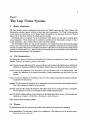
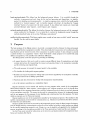
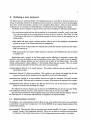
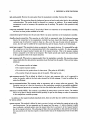
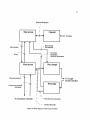
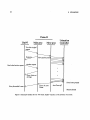
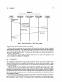
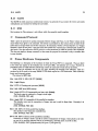
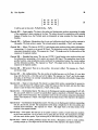
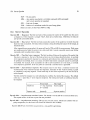
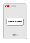
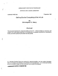
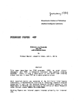
Massachusetts Institute of Technology
Artificial Intelligence Laboratory
Working Paper 272
April 1985
Puma/Cougar Implementor's Guide
Joe L. Jones
Patrick A. O'Donnell
This document is intended to be a guide to assist a programmer in modifying or extending the Lisp Puma
system, the Puma PDP-11 system, or the Cougar PDP-11 system. It consists mostly of short descriptions
or hints, and is not intended to be a polished manual. The reader is expected to be familiar with the use of
the Ptuna system, as described in "Using the PUMA System," and the Lisp flavor system, as described in
the Lisp Machine Manual.
A.I. Laboratory Working Papers are produced for internal circulation, and may contain infornmaiton that
is, for example, too preliminary or too detailed for formal publication. It is not intended that reference be
made to them in the literature.
2
CONTENTS
Contents
I
The Lisp Puma System
1
Basic structure
1.1 File Organization .................................
1.2 Flavors ...................
5
5
5
5
........
.........
.....................
2 Purpose
6
3 Defining a new protocol
3.1 Implementing a protocol .........................................
3.2 Implementing new Request/Response codes ............................
7
7
9
4 Puma Specifics
10
II
10
5
Puma PDP-11 System
Processes
5.1 The Main Process ..........................................
5.2 The Move Process ..........................................
5.3 The Wrist processes .....................................
6 Examples
6.1 A simple informative request: Here .................................
6.2 A motion request: Set Joint Angles ................
6.3 A Wrist-11 request: Read Forces ..................................
6.4 Compliance .........................................
III
...
13
13
13
14
17
................
.
19
Cougar PDP-11 System
7 Overview of Cougar Software
7.1 Background Task ....................
7.2 Data Acquisition .........................................
7.3 Data Processing .........................................
7.4 Communication .........................
..
7.5 Utility ..................................
8
.....
10
12
12
13
Complications
8.1 Intermediate Values .........................................
....
.. . .. .. .. ....
8.2 Wrist Data .. . . ....
8.3 Drift and Offset .......................
..............................
8.4 Data Transfer .. .......
A Cougar Hardware Components
..
.....................
..
..
..
.
..........
.......
....................
...
...
...
. ...
...
...
......
. .
19
19
19
19
19
20
20
20
20
20
20
CONTENTS
3
B Components of the Cougar Software
B .1 INIT . . . . . . . . . . . . . . . . . . . . . . . . . . . . . . . . . . . . . . ... . . . . . . . . .
B.2 JACOB ........................................
B.3 JMOVE ........................
..
.......................
B.4 ADC8 ........................................
B .5 LIM IT . . . . . . . . . . . . . . . . . . . . . . . . . . . . . . . . . . . . . . . . . . . . . . . .
B16 GUTS ........................................
B.7 COMINT ..................
...........
......
.........
B.8 GRAVTY ....................................................
B.9 GUARD . . . . . . .. ... .. . . .. . . . . . . . . . .. . . . . . . . . . . .. . . . . . ..
B.10 FILTER ...........................
..
............ ..
....
B .11 IDR . . . . . . . . . . . . . . . . . . . . . . . . . . . . . . . . . . . . . . . . . . ... . . . . . .
B.12 RATEO ........................................
B.13 NEWPR .......
......
.........
.......
.......
............
B.14 NEWFV ............
.........
........
..........
....
.....
B.15 M ISCOM .............................
....................
B.16 MATH .....................................
..........
........
B.17 END ........................
...
.....
...
...... ... ........
22
. 22
22
22
23
. 23
23
23
23
. 24
24
. 24
24
24
. 24
24
25
25
C Command Protocol
25
D Puma Hardware Components
25
E The
E.1
E.2
E.3
Chaos Manipulator Protocol
User Opcodes .....
..............
......
Server Responses ........
.....................................
Server Opcodes ...........
................
....
...........
................
......
27
27
30
31
CONTENTS
Puma System Connections
Figure 1: Block diagram of the Puma control system.
Part I
The Lisp Puma System
1
Basic structure
The Puma system is really a combination of two systems, the "Manip" system and the "Puma" system. The
Manip system provides a generic interface to almost any type of manipulator. The "Puma" system provides
a small amount of customization to the "Manip" system for specifics of the Unimation Puma arm. Most of
this part of the document describes the Manip system in general.
The Manip system is comprised of a set of mixin flavors which describe the Lisp object representing the
actual manipulator. These flavors may be combined to provide just the functionality necessary to run a
specific manipulator. The pre-defined flavors will be described presently.
The intermediary between the user and the manipulator is a background process that forwards requests
from the user to the manipulator and fields responses from the manipulator. Exactly how the communication
with the manipulator takes place is controlled by the flavors. Information as to the disposition of each request
is stored in a request object (q.v.), which is passed to the background process through a queue stored in the
flavor instance corresponding to the manipulator.
1.1
File Organization
The Manipulator system is divided into several files, all of which are accessed on the "manip" logical host,
directory "source", as in manip: source; def s.lisp.
defs Contains the main definitions of the macros and flavors used throughout the Manip system. Iricludes the
definitions of the Request Defstruct, Manipulator Request Codes, and Manipulator Response Codes.
errors Contains the definitions of the error flavors and error functions used in the Manip system. Also
contains the definitions of the special forms used to handle manipulator non fatal errors in a user
process.
math Contains the definition of "transforms" and a few other random mathematical operations useful for
manipulators or the protocol.
bckgnd This file contains the definition of the background process and the basic communication protocol.
This is the fundamental definition of the protocol.
network This short file contains the definition of the flavor mixin used to communicate with a maniuplator
over the Chaosnet. It serves as an example for other possible implementations.
user The default implementations of user operations on the Manipulator flavor instance. This includes such
operations as :request, :initialize, :disconnect, :move, :here, etc.
utils Contains various debugging utilities.
1.2
Flavors
The defined flavors and their purposes are as follows (all symbols in the manipulator package):
basic-manipulator Theminimum it takes to be a manipulator. This defines some of the primitive operations such as :move, :here, etc.
2 PURPOSE
basic-protocol-mixin This defines how the background process behaves.
It is controlled through the
methods :io-process-top-level-loop, for the top level processing and dispatching; :io-handlepacket, for handling each incoming packet: :io-handle-response-data, called by the handle packet
method for a "normal response;" and :io-handle-request-interrupt, for handling the "request
interrupt" feature of a request (see the users nanual). It also defines how requests are created and
processed through :make-request, :send-request, and :request.
network-protocol-mixin This defines the interface between the background process and the communication medium for the Chaosnet. It, or a mixin like it controls the background process through the
methods described below, in the section "Defining a new protocol."
notify-trivial-errors-mixin This flavor supplies some control on how some so-called "trivial" errors are
handled. See the code for more details.
2
Purpose
The basic purpose of the Manip system is to provide a convenient interface between the Lisp environment
and a non-Lisp Machine manipulator controller. This allows high-level computations to be performed on the
Lisp Machine and the low-level control of the manipulator on another machine. It also attempts to provide
a unified interface to a manipulator "object," which would allow a single program to be useable with many
different manipulators, with possibly only calibration differences.
The Manip system meets this purpose by providing the following:
* A request structure that can be used in common among different types of manipulators, and which
contains instructions for transmitting the request and associated data to the manipulator controller
and for retrieving any response data.
* The code necessary to transmit the request packet to the controller.
* The handlers for dealing with response packets.
* Handlers and support functions for dealing with errors both as signalled by the manipulator controller
and as encountered in the Manip system itself.
* Functions and data structures for dealing with homogeneous transformations.
* A set of common operations on a manipulator object.
Request structures can be created and used by the user program under control of the manipulator
flavor instance using the :make-request, :send-request, and :request operations, and it is through these
operations that the user program communicates with the backgrolmd process its desire to send such requests
to the manipulator controller. The request is also used for communication between the background process
and the user program for the purposes of error handling and retrieving data from the responses. For more
details on requests, see the Puma user manual.
Request packets are sent to the manipulator controller by the background process. The interface to the
specific communication protocol used for communcation (e.g. Chaosnet) is provided by the flavor instance.
See below for more information.
Response packets and errors are received by the background process (using the flavor instance for instructions on dealing with the communications protocol) and are handled according to what handlers are defined
for the specific manipulator protocol in use. Errors, too, can be handled and signalled by the background
process, according to the descriptions provided in the Puma protocol (see below) and the users manual.
See the Puma users manual for information on the structure and implementation of homogeneous transforms and transform-like objects.
3
Defining a new protocol
The Manip system is extremely flexible. The background process is controlled by the flavor instance it is
serving. In particular, whenever the background process attempts to communicate with the actual manipulator server, it does so by sending a message to the manipulator flavor instance. Thus, the exact operation
performed may be controlled by suitably defining or redefining the method handling that message.
The Manip system is designed to support directly any protocol satsifying the following characteristics:
* For each request packet sent from the lisp machine to the manipulator controller, a reply is sent back.
The reply may consist of one or many packets, but there must be at least one. There must be a way
of detecting the last packet of a multiple-packet response in the last packet of that response (e.g. an
empty packet).
a Each packet sent must contain a sequence number, either as part of the underlying communication
protocol or as part of the defined protocol for the manipulator.
* Any packet sent to the lisp machine as a response must contain the sequence number from the request.
This is to match it up.
* Each request packet and response packet contains an operation code identifying what type of request
or response it is.
Implementing such a protocol in the Manip system requires definition of appropriate response data
extractors, and respoise handlers, as well as manipulator request codes. This is made as easy as possible.
However, several response handlers and data extractors are provided by the Manip system. Use of this
already existing support requires adherence to the following defined response opcodes. (For more detail,
consult the protocol description for the Puma robot, later in this document):
normal-response (Opcode 0) A normal response. This contains whatever data are expected from the
request that was sent.
fatal-error (Opcode 1) A fatal error condition. This contains an error string, and implies that the data
connection between the lisp machine and the controller is (or will be) broken (closed).
non-fatal-error (Opcode 2) An error condition that does not close the connection. The packet contains
the error string. This is sent only in response to a request. (This serves as the response to the request.)
asynchronous-error (Opcode 4) This is just like non-fatal-error, but is sent because of a condition
arising not directly in the processing of a request.
The defined data extractor functions may be found in the IICKGND file just after the comment "Define
a few useful data extractor functions," along with the contract they, or new ones, must fulfill.
The next section provides the details of implementing a new protocol, using the same response codes as
the Puma protocol. A later section will detail how to implement new response handlers.
3.1
Implementing a protocol
To implement a new communications protocol, there are just a few methods that need to be provided by
a mixin flavor to manip :basic-manipulator. See the file NETWORK for an example implementation of the
communication protocol.
:may-transmit? This operation takes no arguments and returns non-NIL if it is safe or reasonable to
transmit a packet to the manipulator controller. This is used to allow the underlying communcations
to implement a flow-control scheme and not let the background process get caught in a deadlock.
3 DEFINING A NEW PROTOCOL
:get-next-packet Returns the next packet from the manipulator controller. Returns NIL if none.
:return-packet This operation allows the background process to hand a used packet back to the underlying
communications. The packet should be returned to a resource, or whatever. If no manual memory
management is used or necessary, this operation may do nothing. The packet is this operation's only
argument.
:response-available? Should return T if and only if there is a connection to the manipulator controller,
and there are data packets available to be read.
:connection-open? Returns true if and only if there is an open connection to the manipulator controller.
:handle-closed-connection This operation is called (with no arguments) when the background process
detects the connection to the manipulator controller has been closed (for whatever reason). This
operation may do whatever it needs to clean up. Also, as in the case of manip:network-protocolmixin, the user may be notified of the connection loss, and the reason, if such can be determined.
:send-user-request This operation is given one argument, the request structure. It is responsible for making a packet go out over the communications link to the manipulator controller. It is also responsible
for setting the request-packet-number slot of the request structure. This is the sequence number
which is compared to the value in the response. The request opcode and request data may be found
in the appropriate slots of the request structure.
:get-response-info When given a response packet from the manipulator controller, this operation returns
values which allow the data extractor operations to get the data from the packet. There are four values,
which are:
* The response opcode, an integer.
* The request sequence number.
* The index into the packet where the data starts. (The packet is ART-16B.)
* The number of bytes of response data in the packet. This may be zero.
:get-response-opcode This is defined by default to be just :get-response-info, as it is expected to
return the opcode, which is the first value returned by the info message. It may be redefined by a
mixin for efficiency.
:set-up-communications This message takes no arguments, and no return values are expected. This
operation must see to it that the connection to the manipulator controller is successfully established.
The background process is not running at the time this method gets called, if that makes a difference.
:disconnect NOTE WELL: This method is pre-defined by manip:basic-protocol-mixin. Its mention
here is to say that a daemon method should probably be put on this message to make the connection
to the manipulator controller go away.
In addition to the required methods described above, there are a few that it is useful to put daemons on
for various actions:
:queue-request This method is defined by basic-protocol-mixin, and makes the request get put on the
user-request-queue. Its two arguments are the request and the queue. A :before daemon is useful
here to allocate a network packet, store the request data into it, and save it in the request-packet
slot of the request structure. The advantage of this is that any problems in this activity are found in
the user process at the time the request is created rather than in the background process at some later
time.
3.2
Implementing new Request/Response codes
:initialize This method is used to initialize operation of the manipulator. Useful daemons to put on this
method are clean up operations to make sure everything is in a pristene state, or to make sure that
old connections are gracefully closed, if necessary. Sec the network example.
Useful functions which may be used by a protocol implementation:
copy-manipulator-request-data This function accepts the request, a packet array (ART-16B), and a
starting index in the array and copies the request data into the packet. The operation is fairly intelligcnt, in that it will attempt to interpret the data and store in the packet appropriately. For example,
for a list of objects each elemnent of the list is stored in the packet, in sequence. Note, however, that
a fixnum is always stored as a 16-bit quantitiy, and a flonum is always stored as a 32-bit, PDP-11
style, floating point quantity. The correct type of number must always be passed to copy-manipulatorrequest-data. This function returns the index following the last one stored into.
3.2
Implementing new Request/Response codes
Creating new request codes is easy. Simply use the form (manip: define-manipulator-request-code
symbol opcode) which declares the symbol to be a name for the given opcode. Then when sending a request
via the :request operation, using the symbol will cause the request to have the specified opcode. The
interpretation of the request data will be the same regardless of the opcode, unless the :send-user-request
message (whose responsibility it is to create and send the communication packet-see previous section) makes
some differentiation.
The manip:define-manipulator-request-code form also takes a couple optional arguments. The first
optional argument should be a symbol refering to the type of manipulator which implements this operation. An example would be :puma, for the special compliance operations implemented by that manipulator
controller. Ifthe argument is not specified, or NIL, then the request code is a "generic" code common to
manipulators. (This manipulator type is used in this context mainly to select an appropriate symbol when
given an opcode. This is mostly used for printing things for the user.)
The second optional argument should be a keyword which describes the default data extractor function
to use if none is specified when the request is created. See the code for what keywords are defined and how
to define new ones.
Creating new response codes is almost, as trivial. First, a symbolic name for the response code must be
declared, using (manip: define-manipulator-response-code symbol code), analagous to manip: definemanipulator-request-code. There are no optional arguments.
Second, a handler must be defined for the response. This is where it gets slightly tricky. When a
response packet comes back from the manipulator controller, it contains a numeric opcode. However, different
manipulator protocols may use the same numeric opcode for different responses. Thus, to define handlers
for the response in a new protocol, you must first define a "response handler type." This is done using
(manip: define-response-handler-type symbol). This response handler type must be supplied to the
manipulator flavor instance in order for the background process to look at the new type for response handlers.
The instance variable manip: response-type-list of manip: basic-protocol-mixin isa list of the response
types the manipulator recognizes. By default, this list consists of only one type, manip:generic.
A handler function is created using (manip:define-manipulator-response-handler response-code
type arglist &body body). This will define a function to handle that response. The response-code is
the symbol defined by manip:define-manipulator-response-code, and the type should be one defined
by manip:define-response-handler-type. The function is passed three arguments: the manipulator instance, the response packet, and the requests in process queue. The body of the handler is expected to do
whatever is necessary to process the response packet. However, the background process itself will return the
packet using the :return-packet operation, unless the form (manip: dont-return-pkt! packet) is used.
The background process does not expect any return value from the handler.
When the background process looks for a handler for a response packet it looks at the manip:responsetype-list for the response handler types, and uses the first handler it can find by looking down that list.
5 PROCESSES
Thus, the order of the types matters. Furthermore, a handler may allow handlers defined by other types to
participate in the handling of the response by calling the form (manip: continue-manipulator-responsehandler manipulatorpacket queue).
Note that the handler functions which are defined by the Manip system simply send a message to the
manipulator with the naine :io-handle-..., all of which are combined using :OR method combination.
Thus it would be quite simple to slightly modify the handling of these responses by suitably defining methods
in the appropriate mixin.
The handling of responses may be further customized or radically altered by suitable definition of overriding methods for the :io-handle-packet or :io-handle-response-code messages. See the code.
The following are a few functions which the implementor may find useful in implementing responses. All
are in the MANIP package. For details, see the code.
find-matching-request
response-packet-string
signal-error-for-request
signal-error-for-request- 1
signal-error-for-out-of-sequence-request
4
Puma Specifics
There is very little that is really specific to the puma, except for certain customizations of various operations
and compliance. All the compliance operations are specific to the Puma, but they mostly consist of merely
passing matrices and information to the wrist-11 through the Puma-1l.
Part II
Puma PDP-11 System
This part is a brief overview of the control system running in the Puma PDP-11/23. It is intended as an
introduction for prospective programmers to become acquainted with the overall structure of the system.
More detailed information is available in the comments in the actual code. This document assumes that the
reader is familiar with the structure of the network protocol used to communicate with the Puma.
5
Processes
The system is built on the Minits operating system. Minits provides a handy facility for very simply
configuring a PDP-11 system with various hardware components. Of interest to the Puma system is the
Chaosnet support, and Minits' multiprocessing capabilities.
Minits has a rather simple scheduler, which selects a process to run based (roughly) on a priority using a
round-robin selection between processes with the same priority. The Puma system runs in four separate processes: a main process, which communicates with the foreign host over the network and handles its requests,
and three ancillary processes. Two processes communicate with Cougar, the wrist PDP-11, one handling
data transmitted from Cougar, and one sending requests to Cougar. One process, the "move" process, handles communication with the Unimation controller and calculates the trajectory for the manipulator. The
latter process is not scheduled by Minits, but is interrupt driven-basically it is the interrupt service routine
for servoing the arm. The move process also provides support for compliant motion.
Requests/Responses
To User
Move packets
Errors
New joint positic
To Cougar
Parallel interface
Currentjoint posi
Arm sta
To Unimation controller
New Theta Dot commands
-
Positio//Rateinfo
Figure 2: Block diagram of the Puma processes.
5 PROCESSES
These processes are created only when the connection is established between the foreign host and the
Puma server. The main process is created through instructions provided to the Chaosnet software; it, in
turn, creates the wrist and move processes. When the connection is closed, all the processes are destroyed.
The main process is defined in the file PUMA.PALX. The move process is defined in MVPROC.PALX.
Low level utility routines, including all the routines used to communicate to the Unimation controller are
found in PMUTIL.PALX; arithmetic utilities are in ARITH.PALX. The compliance support and wrist PDP11 communication processes are defined in COMPLY.PALX. Calibration routines are in CALINF.PALX.
5.1
The Main Process
When a request for connection is received by the Puma-ll, the main server process is created and started. The
process initializes the Unimation hardware, sets up the software database, creates the ancillary processes,
and enters a loop waiting for request packets from the foreign host. When a request packet is received,
the process dispatches to the appropriate handler routine for the request, performs whatever actions are
necessary to satisfy the request, then sends a response packet to the foreign host. If a condition arises or is
discovered which prevents successful completion of the request, the "response" will be indicate an error.
The main process is also responsible for reporting error conditions discovered by the remaining three
processes; it is the only process which actually communicates to the network. The ancillary processes store
error information in a buffer, which is checked each time through the main loop. Any errors which are found
there are passed on to the the foreign host.
If the connection is closed, either by the foreign host, or by a fatal error condition, the main process shuts
down the system. It informs the two wrist processes that they should log themselves out, turns off clock
interrupts which effectively shuts down the move process, makes sure the connection is closed and released
to the Minits Chaosnet code, then logs itself out.
When a request is received which requires action from any of the ancillary processes, such as a request
to move the arm or to send a new matrix to Cougar, the data portion of the request is copied into a "move
packet" or a "wrist packet", as necessary, and linked onto a queue of similar requests to be handled by the
appropriate process. Once this is done, the main process returns a response to the user, without waiting for
the request actually to be handled by the move or wrist process. This is so that the foreign host may send
several such requests in succession, allowing the Puma-ll to process all the motion requests and provide
smooth transitions between requested segments. However, if the request itself requires information from the
appropriate ancillary process (for example, an "Examine Wrist" command), the main process will indeed
wait for the data to be returned.
5.2
The Move Process
The move process is actually the interrupt service routine for the programmable clock. It is activated every
sixteen milliseconds, performs the calculations necessary to keep the arm moving (or stationary) in the
requested trajectory: checking for possible collisions with the enviromnent, calculating the next set of joint
angles, communicating with the Wrist-11 for compliance, and sending new joint angles to the Unimation
controller.
Collisions are tested for by checking that the arm actually arrived at the joint angles that were requested
of the controller in the previous servo cycle. If the current angles are not within a small tolerance, the
arm is stopped where it is and an error indication is queued to be sent to the foreign host. However,
under compliance, we do not expect the arm to necessarily get within the tolerance limit, so the collision
test is inhibited. We depend on the compliance calculations to handle interaction with firm objects in the
enviromnent.
There are five interpolation schemes available in the move process: a linear interpolation with quadratic
transitions between segments, a fifth-degree polynomial. interpolation providing zero velocity and acceleration
at the endpoints of the segment, a "cosine wave" interpolation which varies a single joint's angle along a cosine
curve-this is intended for debugging only and should not be used in normal operation, and two compliant
5.3
The Wrist processes
motion interpolations, one for debugging the compliance code, and one for motion. The compliant motion
interpolation calculates the trajectory based on the linear/quadratic interpolation, then adjusts it based on
its communcation with Cougar.
Each segment of the trajectory may use any one of the interpolation schemes, although some of them
are not compatible for smooth motion. To calculate the next joint angle vector to send to the Unimation
controller, the move process merely dispatches to the appropriate interpolation routine.
When performing compliance, the move process communicates with Cougar via the two wrist processes.
Each servo cycle, it requests the output wrist process to send a "New Position and Rate" command to
Cougar. The input wrist process will accept "New Theta Dot" commands from Cougar, and will store the
velocity modifications in a buffer, from which the compliant interpolation scheme will accept the information
to use in its calculations. (See the code for more details.)
5.3
The Wrist processes
The two wrist processes handle all communication with Cougar. One process handles commands and data
to be sent to Cougar and the other accepts commands and data from Cougar and interprets them.
There are two types of command which may be passed between Puma and Cougar: commands directly
associated with servoing the arm under compliance, and commands in response to user requests. Of the
former, examples are the "New Position and Rate", "Reset Wrist", and "New Theta Dot" commands; of the
latter, examples are "Read Forces", "Set Wrist Gauge Offsets", and "Force Data". Processing the commands
associated with the servo loop is optimized for better response time from Cougar. Unlike user requests, which
are queued as "packets" to be sent to Cougar, move process requests are "queued" merely by setting a bit
in the wrist process flag word. These flag bits receive higher priority handling than mere user requests.
Further, if the wrist output process is quiescent, the interrupt routine itself will put the data in the outgoing
ring buffer. This saves process switching time and the associated latentcy.
The move process also briefly handles some user requests-those which must be synchronized with move
segments. These requests are queued by the move interrupt routine for the wrist output process to send to
the wrist. A separate queue is kept for requests coming directly from the user through the main process.
The priority order for dealing with requests for sending commands and data to Cougar is as follows: First,
"New Position and Rate" commands; next, "Reset Wrist" commands; then the two "wrist packet" queues,
the interrupt queue and the normal user process queue.
6
Examples
What follows are a few examples of the life history of a request from the foreign host through the main
Puma process and possibly through the ancillary processes and Cougar. (See the accompanying figures.)
6.1
A simple informative request: Here
The "Here" request is received by the Puma-ll. The top level loop dispatches to the HERE handler routine.
The current joint angles are retrieved from the global data buffer where they are always stored (the move
process updates them every servo cycle), and the forward kinematics are applied to them, resulting in the
desired transform. The 3x4 transform is then returned to the foreign host.
6.2
A motion request: Set Joint Angles
The main process verifies that the desired joint angles are in range for each of the joints. Then the angles,
together with the desired interpolation scheme are stored in a move packet and queued to the move process.
The main process now responds to the user with a motion segment sequence number. As far as it is concerned,
handling of the request is completed.
6 EXAMPLES
LispM
Puma-ll
ulate transform
currentjoint
I
Figure 3: Example timeline for the "Here" request.
The move process notices the new packet on its queue, and begins processing the segment. Based on
the interpolation type, the process dispatches to an initialization routine, which may set up the interrupt
processes global database to handle the interpolation from the arm's current position to the desired position
from the move packet. Then, on each servo cycle, new intermediate joint angles are calculated by the
interrupt service routine and sent to 'the Unimation controller. This will continue until the arm reaches the
desired position. The move packet is then returned to free storage; the handling of the original request is
complete.
Let us here consider the effect of error conditions on the above behavior. First, assume one or more of
the joint angles requested by the foreign host are out of range. This would be detected by the main process
before queueing the move packet. Instead of a normal response, the user would receive a non-fatal error
message.
Now, let us assume that the angles are valid, and the arm starts moving, but that in the midst of the
motion, the user presses the "panic button", shutting off power to the arm. The main process has, in fact,
returned a positive response to the user, indicating that the motion segment has been successfully queued.
The move process, however, will detect the power off condition on the next servo loop, and will cause an
asynchronous error to be signalled to the user. It will also abort the current segment as well as any further
queued move packets. Further motion requests will be refused until the abort condition is reset. Then
operations will proceed as before.
6.3
A Wrist-11 request: Read Forces
When the user requires data from Cougar, the main process must send the request for the data to Cougar,
then wait for a response. The sequence of operations is as follows: The request is received by the main
process, which translates it into a request to Cougar. In this case, before Cougar can return accurate,
gravity-compensated, force and torque information, the current arm position must be supplied to it. Thus,
the request handler first queues the the current joint angles to be sent to Cougar, followed by the request
6.3 A Wrist-11 request: Read Forces
Puma-ll
LispM
Main proc
Unimation
Controller
Move proc
I
"Set Joint Angles"
request
I
Move packet queuea
'S.--=--5-
Response
Newjoint angle commands to
the Unimnation controllerevery
sixteen milliseconds
0-----
"Here" request
S
Otherrequests may be
serviced while motion - Response
is in progress, including
more move requests,
which are queued. "MoveMove packet queued
Response
'5
'5-=
- -5--
Motion completed
Figure 4: Example timeline for a "Set Joint Angles" request. (A move request)
16
6 EXAMPLES
Puma-ll
LispM
Maih1 proc
Move proc
I
"Set Joint Angles"
request
Response
Send a bad motion request
Unimation
Controller
Movepacket queuea
Another request
*
Error: Joint out
ofrange
A
Error forwarded to user
Error: No Arm
Power
o
Panic buttonpressed
Arm Power off
Motion aborted
Figure 5: Example timeline for the "Set Joint Angles" request, in the presence of an error.
6.4 Compliance
Puma-ll
LispM
Main proc
Wrist Output Wrist Input
Cougar
"Read Forces"
request
"Sensed Angles"
Readforces"
Commands
Waitsfor data...
Force data
Response
Figure 6: Example timeline for a "Read Forces" request.
for the force data. It then waits for the data to be returned.
The wrist output process notices the queues requests and forwards them to Cougar, through the parallel
interface interrupt ring buffers. When Cougar responds with the current forces and torques, the wrist input
process fields the response, stores the data into the buffer supplied by the main process, and notifies the
main process that the data has arrived. The main process then reawakens and forwards the data back to
the user in a response packet.
If Cougar should not respond within a reasonable amount of time, the main process will give up, and
return a non-fatal error message to the foreign host.
6.4
Compliance
Not surprisingly, compliant motion causes the most interaction between the various components of the
system. The main process treats a compliant motion request as it does any other motion request. It copies
the desired joint angles into a move packet, along with the compliant move interpolation vector, and queues
it to the move process.
The move process, too, treats compliant motion segments no differently than normal motion. When
the segment's turn comes up, it dispatches through the move interpolation vector to initialize the segment,
interpolate to the desired position, and clean up after the segment. The interpolation routine for compliant
motion, however, does more. In the course of calculating the set of joint angles for the next servo period, it
calls the normal motion interpolation routine to determine the nominal position, but then involves the two
wrist processes and Cougar.
On each servo cycle, the compliance interpolation routine causes a "New Position and Rate" command to
be sent to Cougar. It will do this itself if the wrist output process is quiescent, or will set the flag to inform
that process that it needs to be done. The command is sent to Cougar, who then calculates and returns
6 EXAMPLES
Puma-ll
LispM
Main proc Move proc
Wrist I/O
Cougar
Unimation
Controller
Figure 7: Example timeline for a "Comply" request. Note: This diagram assumes that the Wrist output
process is quiescent when the move process whishes to transmit New Position and Rate requests to Cougar.
If the output process should be in the midst of transmitting data, the NewPR requests would first go the
the output process, then on to Cougar.
the next velocity modification. The input process receives the "New Theta Dot" command and stores the
data in a buffer, from which the interpolation routine will use them. This interaction takes time, however; it
takes longer than the servo rate. Thus, on the same cycle that the interpolation sends a NEWPR command,
it uses NEWTD data from a previous cycle--the latest that Cougar has sent.
This interaction continues to occur for each servo cycle until the motion is complete, at which time, the
normal clean up handling takes place, and a new segment is started, or the arm brought to a smooth stop.
Note also, that while the compliance is taking place, other interactions may be taking place between the
user and Cougar, involving the wrist input and output processes.
Part III
Cougar PDP-11 System
7
Overview of Cougar Software
The routines running in Cougar can be roughly divided into five classifications. They are: the background
task, a data acquisition module, a data processing module, a communications module, and a package of
utility programs.
7.1
Background Task
In order to convert between joint and cartesian space, as the processes in Cougar must do, it is necessary
to have an up to date Jacobian transformation matrix available. Cougar is given joint position information
by Puma from which it computes the Jacobian. The subroutine which does this runs continuously, even
recomputing the Jacobian when no new data have been received. All interrupt driven routines, however,
have priority over it.
7.2
Data Acquisition
The prime function of Cougar is to acquire data from the force sensing wrist. This it does under the control
of an interrupt driven routine operating at the servo rate. That rate is decided by Punma which provides the
clock signal to trigger Cougar.
The force sensing wrist has eight strain gauges each of which is connected to a channel of the A/D
converter in Cougar. When gathering data from the wrist each channel in turn is triggered to start a
conversion, Cougar waits for the conversion to finish, and the result is stored for later processing.
7.3
Data Processing
Following its acquisition, the digitized strain gauge data is multiplied by a conversion matrix to transform
it into force-torque vector. This along with other data from Puma is entered into the compliance equation
to compute a new incremental velocity vector. Also in this process is the computation of the gravitational
correction and and a test of any motion guards which may be set.
7.4
Communication
Certain commands can be passed between Puma and Cougar. The data which constitutes these commands
travels between the DRV-11J cards in the two computers. Interrupt driven routines, which trigger on the
completion of the previous transfer, send and receive data words. Buffers are used to hold data going in each
direction. As a part of the main Puma triggered interrupt routine, the input buffer is checked for complete
commands which are executed as they are found.
8
7.5
COMPLICATIONS
Utility
Many subprograms serve as utility routines. These include, in particular, the routines in the math package.
8
Complications
Not all of the Cougar system operates in as straight forward a manner as would be desired. This sections
outlines some of the difficulties.
8.1
Intermediate Values
The Jacobian, its transpose, and several intermediate values for the compliance equation are computed by a
background operation. As they are used by an interrupt driven routine we must guard against the possibility
that they will be referenced when only partially computed. This is accomplished by keeping two versions
of each object - one for the background and one for the foreground process. When the background process
finishes each computation it switches the pointers which define background and foreground for that object.
8.2
Wrist Data
The RTI force sensing wrist provides analog data in the range of -10 to +10 volts. This is converted by the
ADC to a 12 bit range. The data thus presented, however, is not the force nor is it directly interpretable as
a voltage, it is just a set of eight numbers (one for each strain gauge) with values between -2048 and +2047.
To get the force information these must be converted by applying the wrist's calibration matrix. In order
to avoid a multiplication each servo cycle the calibration matrix is premultiplied by a conversion constant
10/2048 which by itself would convert the gauge readings into values in the range of -10 to +10. But this
is not all. For compliant motion it should seem to the robot that any force read from the sensor are forces
which it has applied rather than forces applied to it. To achieve this we further multiply the calibration
matrix by -1. And finally, we want the capability to choose the center of compliance - to have the forces
reported and used by the system be the forces that it would read directly if the wrist was at the center of
compliance. This requires another transformation matrix which is multiplied into the previous one. It turns
out that only certain of the elements of this final matrix depend on the position of the compliance center so
rather than actually perform another matrix multiplication the proper elements are modified individually.
This is done automatically each time the frame vector, the position of the center of compliance, is changed.
8.3
Drift and Offset
The force sensing wrist suffers from two chronic maladies, drift and offset. Simply reading the raw data from
the wrist with no force applied (including gravity) would not result in a value of 0 from each of the strain
gauges. The non-zero values one reads in the absence of forces are the gauge offsets. Also, taking the same
reading on different days would produce different values, this is the drift. To correct for the offset an eight
element vector is subtracted from the gauge readings prior to any other processing. Unfortunately, because
of drift this value cannot simply be stored in Cougar for all time but must be recomputed periodically. This
is the purpose of the 'Calibrate-Wrist' command. It computes a gauge offset by reading the wrist force
sensor in two positions to compensate for gravity.
8.4
Data Transfer
If IDXS, the interrupt driven transfer send routine, is running then each time Puma receives a character
it sends a control signal back to Cougar which causes and interrupt that initiates the sending of the next
character. If, however, the routine is not running it will never get an interrupt to start a new transfer; this
would mean that characters for transfer would pile up in the output buffer. It is necessary, then to turn on
8.4 Data Transfer
21
IDXS whenever data needs to be sent. But this must not be done blindly, if IDXS is restarted when it is
already running (i.e. has just sent a character and is waiting for an interrupt) then it would send the next
character before Puma was ready. This problem is handled by adding an "in-progress" bit to IDXS. This bit
is turned on when the routine is initially called and turned off by IDXS when it empties the output buffer.
The turn on routine never starts IDXS if the in-progress bit is set. There are no such problems with IDXR,
the receive counterpart of this routine.
B COMPONENTS OF THE COUGAR SOFTWARE
Appendix
A
Cougar Hardware Components
The Cougar system is composed of these hardware components:
* An SA-BAII-N 8 slot backplane with power supply and line time clock
* An LSI-11/23 processor with FPF-11 floating point accelerator board
* An MXV-11AA board with bootstrap ROM.and terminal port
* A Data Translation DT-2762 A/D converter
* A KWV-IIC programmable clock
* A DRV-11J four port parallel 16-bit IO board
* A Chaos net board
* A 128k memory board with memory management
* An RTI Force Sensing Wrist
Physically port C of the DRV-11J is used for input and port D for output each being connected to its
counterpart on Puma's DRV-11J. The KWV-11C is operated as a slave and is driven by the KWV-11C in
Puma. Cougar should be operated with the line time clock switched to off.
B
Components of the Cougar Software
Each of the following subheadings is a PALX file in the Cougar system. Most are also the label of the
principal subroutine in that file.
B.1
INIT
The INIT routine is executed exactly once when the Cougar system is loaded. Among other duties it sets up
the addresses and vectors of the various interrupt driven routines, it initializes the DRV-11J, and the clock,
and prints a wake up message on the terminal if one is connected to port 0 of the MXV-11AA. It then sets
a low priority in the processor and jumps to JACOB.
B.2
JACOB
The Jacobian routine JACOB runs continuously, subject to interruption from any of the interrupt driven
processes. The MACRO-11 code which actually executes the Jacobian calculation is produced by a microcompiler written in lisp (JACL.LISP). This compiler operates on code modified somewhat from a Jacobian
routine originally written in Pascal. The transpose of the Jacobian is stored explicitly immediately following
the Jacobian.
B.3
JMOVE
Jmove repositions the Jacobian and its transpose. For historical reasons the Jacobian is computed in the
region labeled J, then moved to either jtmpl or jtmp2.
B.4 ADC8
B.4
ADC8
ADC8 at once acquires and filters force data from the wrist. For each of eight channels it initiates a
conversion, waits for completion, and processes the result according to the formula:
Yk = [k + Uk-1 + 6Yk-1]/8
Where Yk is the kth output value, Uk is the kth force sample, uk-I is the previous sample and Yk-1 is
the previous output value. The equation is implemented in such a way that floating point operations are
not required. The arithmetic is done with shifts and adds. When the servo rate is 60 Hz a cutoff of 2.8 Hz
is obtained in the force information. It would be possible to operate the ADC on an interrupt driven basis
but as the conversion delay is a minor part of the total computation time this has not been done.
B.5
LIMIT
To promote stability LIMIT puts bounds on the minimum and maximum forces to which the system is
sensitive. Any force-torques below an absolute value of .5 oz / .5 oz-in are set to 0 and any above 500 oz /
500 oz-in are set to 500. These limits are easily changed by altering the 'tol' or 'dead' constants in LIMIT.
At present the LIMIT code, while available in the system, is not actually used.
B.6
GUTS
When Puma's clock ticks the interrupt routine GUTS is called in Cougar. GUTS in turn calls ADC8 to
get the filtered strain gauge readings, converts them to floating point, and multiplies by voltniat to get the
forces. Subsequently, GUTS calls GRAVTY to make the gravitational correction, calls GUARDM to check
for tripped guards and calls COMINT to process any commands that may be in the input buffer. GUTS is
non-reentrant and so must never interrupt itself. This condition is checked for on entry into GUTS and if
detected a character is sent to the terminal and a return from interrupt instruction is executed.
B.7
COMINT
As data is transferred from Puma to Cougar it is stored in an input buffer. When COMINT is called it
examines that buffer to see if any data is there. Commands consist of a code word (unique to the particular
command) followed by some characteristic number of data words. If the buffer is non-empty COMINT
checks the first word in a look-up table to see how much data this command requires. On finding at least
that many words in the buffer COMINT removes the command from the buffer and transfers its data to a
location also found from a table. Finally COMINT calls the subroutine which will execute this particular
command. When it terminates COMINT looks for more complete commands in the buffer. If none are found
COMINT returns. All available commands are listed in Table 1. If COMINT detects an unrecognized code
word it takes drastic action. It assumes that it has lost sync with Puma and so dumps the input buffer and
sends an 'out-of-sync' message to Puma.
B.8
GRAVTY
At any instant the forces reported by the wrist will be the sum of gravitational and contact forces operating
on the hand. Compliant motion strategies require that the robot respond to contact forces, so it is convenient
to remove the component of force due to gravity. This the GRAVTY routine does by keeping track of the
orientation of the hand, and subtracting from the measured force the part for which gravity is responsible.
The gravity correction code uses a simple model of the hand and the object it holds to compute the expected
forces. Each is modeled as a point mass at some position in the frame specified by the frame vector. Whenever
a new object is picked up or the frame vector is changed NEWEWC must be called to record the weight and
center of gravity vector of that object.
B
B.9
COMPONENTS OF THE COUGAR SOFTWARE
GUARD
Two types of guards are allowed. The first type instructs Puma to stop moving immediately. The second
just informs Puma that a guard has tripped. In either case Cougar reports the number of the guard which
tripped. That guard then becomes inactive and will not trip again unless another GUARDS command is
issued. The high byte of the first data word in the GUARDS command determines which type of guard
is activated. A maximum of 16 guards may be active at any time. The number of the guard to activate
occupies the low 4 bits of the first data word. The Lisp Machine must keep track of which guards are in use
and provide a number when the user wants to activate a new one. The guard code uses the gravitationally
corrected sensed forces to decide if a trip has occurred so the NEWFV and NEWEWC commands should
not be used while a guard is active.
B.10
FILTER
FILTER is an output routine which smoothes the output. It computes a weighted sum of the derivative and
integral of the controlled quantity using the formulas:
AbFiltered = [con,(Absample - APreviouls Sample) - conlAOF i tered]
Aboutput = con3SAFilered + con4Absample
Where: con, = 2/(aT + 2), con 2 = (aT - 2)/(aT + 2), T = Sample Period, a = cutoff frequency and,
a < 1/2T. The constants cons and con 4 determine the relative importance of the raw quantity and the
filtered quantity.
B.11
IDR
These are the Interrupt Driven Routines. They now include only the data send and receive routines IDXS
and IDXR.
B.12
RATEO
RATEO does nothing more than to put the newly computed compliance rates into the buffer from which
they will be sent to Puma.
B.13
NEWPR
The most important command - the one executed every cycle during compliant motions, is NEWPR. It gets
from Puma the currently sensed and commanded position, and the difference between sensed and commanded
rate and computes an incremental velocity to send to back to Puma. The equation it implements is the
compliance equation discussed in section 1.
B.14
NEWFV
Newfv (which stands for New Frame Vector) changes the compliance center to the point specified in hand
coordinates. It can only cause a translation. It forces a recomputation of the strain gauge calibration matrix,
as explained in the Complications section, and causes the model of hand-object combination in GRAVTY
to be redone.
B.15
MISCOM
The routines in the file MISCOM execute miscellaneous commands which are explained below in the Remarks
column of the Command Protocol section.
B.16 MATH
B.16
MATH
The MATH file holds numerous mathematical routines. In particular it has routines for vector and matrix
multiplication and routines for finding sine and cosine.
B.17
END
End contains the Palx statement .end without which the assembler would complain.
C
Command Protocol
Table 1 gives the protocol for passing commands between Cougar and Puma. In the 'Name' column is the
name which Puma gives to the command. The letters in parentheses in that column form the label of the
subroutine in Cougar which executes the command. All commands, whether a 'Puma Request' or a 'Cougar
Response' consist of two parts: a one word code that specifies the command and a characteristic number of
data words. Note that subroutine NOOP (which is a return statement) is called for several of the commands.
This does not signify a dummy command, in these cases the purpose the command is only to transfer data
to some location.
D
Puma Hardware Components
The following is a description of the hardware of which the Puma PDP-11 is composed. They are listed
in the order they appear in the backplane (as of 16 April 1985). All addresses are in octal. Numbers in
parentheses after the CSR addresses indicate the number of consecutive words used by the device.
Table 2 lists the addresses used on the I/O page, including all internally used addresses.. This is a
complete list of all words in the range 760000-777776 which respond to a TST instruction. Table 3 lists the
known used interrupt vectors.
The devices by QBUS slot:
Slot 1 left KDF-11 LSI-11/23 CPU (M8186)
Slot 1 right Empty
Slot 2 FPF-11 Floating point processor (M8188)
Slot 3 left 256K bytes MOS memory
Slot 3 right KWV-11C Programmable real time clock (M4002).
The clock output is connected to Cougar's clock input.
[CSR: 170420(2); VEC: 440]
Slot 4 right DRV-11C-compatible 16-bit parallel line interface.
This interface once was the connection to Cougar, but now is used for finger data. Currently, it is
unconnected.
[CSR: 167760(3); VEC: 210]
Slot 4 left DRV-11C 16-bit parallel line interface.
The interface to the Unimation controller box.
(CSR: 167770(3); VEC: 200]
Slot 5 left DRV-11J (fancy) 16-bit parallel line interface.
Connection to Cougar. Ports C and D are used to communicate to Cougar. Some places in the code
use port A for metering (flipping bits for an oscilloscope), otherwise ports A and B are free.
[CSR: 164160(8); VEC: (programmable) 220 (port C), 224 (port D)]
D PUMA HARDWARE COMPONENTS
Name
(Label)
NOP
Puma Request
Code
Data
Cougar Response
Code
Data
- none -
(noop)
WINIT
(noop)
SEN
(noop)
FINIT
(noop)
NPR
4
none
- none -
6 fvec
- none -
6 fvec
- none -
3 x 6 fvec
1
6 fvec
(newpr)
6 fvec
- none -
6 fvec
- none -
NB
(newb)
NBJI
(newbji)
NFV
(newfv)
36 fmat
- none -
6 fvec
- none -
3 fvec
- none -
RST
(resetw)
DPST
(dep)
EXMN
(exp)
none
- none -
2 words
- none -
NFC
(noop)
NK
New Joint Damping Matrix Inverse - diagonal terms only.
New Frame Vector - a vector offset from
the intersection of joints 4, 5, and 6. This
defines the center of compliance.
Reset Wrist - set all velocities to zero.
2 words
4
>2 words
1 word
8
1 word
none
5
6 fvec
(verson)
RFRC
(rfrc)
NEWEWC
15
wt 1 fnum
cg 3 fvec
16
type/index
dvec 6 fvec
tol 1 fnum
(newewc)
GUARDS
(guards)
GUARDC
- none -
6
7
index
index
- none -
index
(guardc)
RRAW
none
8 vec
0
(reraw)
WGOV
(noop)
8 vec
Theta Sensed - Tells the wrist where the
arm is so that gravity compensation will
work even while compliance is inactive.
Full Init -- data is sensed position, an obsolete command.
New Position and Rate - Gives sensed and
commanded position and the difference of
the sensed and commanded rate. Response
is Ao.
New Force Commanded.
New Spring Constant a matrix of diagonal
terms only.
New Damping Matrix - a 36 element matrix
(newk)
VERS
Remarks
No-operation. Useful for recovering from
synchronization errors.
Wrist Init, an obsolete command.
;;
- none -
Deposit - deposits the second word into the
location specified by the first word.
Examine - start at first word, return second word number of words. Response: first
word - number of words retrieved, rest data words.
Version Number - intended to ensure consistency between Cougar and Puma, it is
not currently used by either side.
Report Forces - report most recent sensed
force from wrist.
New Effective Weight and Center of Gravity
- The cg is the offset from the frame vector.
Weight of object in ounces.
Guard Set - 1st word hi bit set * trip
stops move (response = 6). Clear =$ continue move (response = 7). dvec = vector
to dot with force, tol = scalar to test, index
= number of guard.
Guard Clear - Ignore guard specified by index.
Read Raw Wrist Gauges - returns readings
from each of the 8 wrist strain gauges.
Write Gauge Offset Vector - Specifies the
vector which is subtracted from the raw
gauge readings.
Table 1: Puma-Cougar protocol commands
Address
764140 764152
764156
764160--764176
767760-767764
767770-767774
770420-770422
772300--772316
772340-772356
772516
773000-773776
776500-.776506
777546
777560--777566
777572-777576
777600--777616
777640-777656
777776
Device
Chaosnet interface
???
Cougar interface (DRV-11J)
Finger interface (DRV-11C)
Unimation interface (DRV-11C)
Real time clock (KWV-I11C)
Mem. Mgt. Kernel PDR
MM Kernel PAR
MM Status register SR3
Boot ROM (MXV-11)
Serial line 0 - teach box (MXV-11)
Line time clock (internal)
Serial line 1 - console (MXV-11)
MM Status registers
MM User PDR
MM User PAR
Processor Status Word
Table 2: I/O Page addresses
Slot 5 right MXV-11AA Multi-purpose module.
Contains bootstrap ROM for network bootstrap, two asynchronous serial lines, and (unused) memory.
The two serial lines are used as the console line and for the teach box. Both serial lines are configured
to be 9600 baud, eight data bits, no parity, one stop bit.
[Serial line 0: CSR: 176500(4); VEC: 300]
[Serial line 1: CSR: 177560(4); VEC: 60]
Slot 6 Chaosnet interface.
[CSR: 164140(6); VEC: 270]
E
The Chaos Manipulator Protocol
[This section is a slightly edited version of an unpublished document written by Patrick Sobalvarro.]
A connection is opened by connecting to the server for the robot on that machine. There should be one
server for each robot on the machine. Once the connection has been established, the user should wait for
the server to send a RESPONSE packet, and then it's no holds barred.
The rest of the protocol can be described with opcodes. We use the 8-bit data series (opcodes 200-277)
as commands from the user. Information is returned as described per-opcode below.
NOTE: Where floating-point data are specified, the format used is PDP-11 single-precision (32 bits).
E.1
User Opcodes
Opcode 200 - describe self: The manipulator should respond with a stream of response packets, terminated with an empty response packet. The packets should contain a Lisp-readable ascii description of
the manipulator connected to. We use an ascii description for clarity and because speed is not terribly
important in a describe self operation. The description is an alist. Following is a list of allowable
descriptors and their definitions.
E THE CHAOS MANIPULATOR PROTOCOL
Address
4
10
14
20
24
30
34
60,64
100
114
200,204
210,214
220,224
240
244
250
270,274
300,304
440,444
Use
Time out (not normally handled)
Illegal instruction (not handled)
BPT instruction- debugging
IOT instruction--MINITS scheduler
Power fail-Not yet handled-will be in future
EMT instruction-MINITS system calls
TRAP instruction-MINITS unexpected interrupt handler
Console serial line (MXV-11 line 1)
Line clock (used by MINITS)
Memory parity error (unhandled)
Unimation interface (DRV-11C)
Finger interface (DRV-11C)
Cougar interface (DRV-11J) (programmable)
PIRQ (not handled)
Floating point exception
Memory management (not handled)
Chaosnet interface
Teach box serial line (MXV-11 line 0)
Real time clock (KWV-11C)
t
I.!
Table 3: Known esed interrupt vector addresses. This also includes trap addresses, for completeness.
:brand-name is a Lisp Machine Lisp-readable string (i.e., delimited by double-quotes, etc.) that
contains the name of the manipulator. E.g., "Unimation Puma 600"; "Purbrick Arm"; "Salisbury
Hand Finger #1".
:unique-name is like :BRAND-NAME, but should be a unique identifier of the robot. Thus if the.
AI Lab had two Puma 600s, their :UNIQUE-NAMEs might be "Puma 600 #1" and "Puma 600
#2", or "Trurl" and "Foo".
:degrees-of-freedom should be an octal number giving the number of degrees-of-freedom of the
manipulator. Examples: the Puma returns 6 for this; so would the Purbrick arm.
:operations Should be a list of opcodes supported by the server. An opcode is normally an octal
number; e.g., 200. In the case of escape codes, an opcode can be a dotted pair, e.g.: (277 . 0).
:software-version is manipulator dependent. It should be either a number indicating the version of
software being run on the server host, or a list of alternating keyword and version number pairs.
For instance, the keywords may indicate the module name, and the version number would indicate
the version of that module.
:protocol-version is the version number of this protocol. The version described here is version
number 1. All protocol versions must support the describe self operation identically.
There should probably be more stuff here, like things to describe the geometry and touch and forcesensing, so that a program could conclude whether a manipulator is capable of performing a function,
but I haven't given much thought to that yet.
Opcode 201 - Here: The response contains a sequence of floating-point numbers giving position information. The position information returned is a 3x4 matrix, the first three columns being a rotation
matrix, and position in the fourth column, represented in column-major order. Thus if we represent
the rotation matrix as:
E.1
User Opcodes
Nz Ox Ax Pz
Ny Oy Ay Py
Nz Oz Az Pz
(1)
It will be sent in this order: NxNyNzOzOy ...PyPz.
Opcode 202 - Joint angles: The data in the packet are floating-point numbers representing the angles
of the manipulator's joints, starting at the base. The values returned by manipulators with extensile
degrees of freedom (e.g., the Purbrick arm) are interpreted as being cartesian for those degrees of
freedom.
Opcode 203 - Calibrate: Manipulators that do not need calibration should send a positive response to
this packet. The data section is empty. The returned packet is essentially a "done", and is empty.
Opcode 204 - Move: The data are 12 PDP-11 style floating point numbers giving position information,
representing a 3 x 4 matrix, as in opcode 201 (here). The manipulator moves to the specified position,
using joint-interpolated motion. The response is a "done". The single word in the data section of the
response is the segment number.
Opcode 205 - Straight-line move: The data are 12 PDP-11 style floating point numbers giving position information, representing a 3 x 4 matrix, as in opcode 201 (here). The manipulator moves to the
specified position, using straight-line motion produced by interpolation between the current position
and the destination position. The response is a "done". The single word in the data section of the
response is the segment number.
Opcode 206 - Kill power: There is no data section. Arm power is killed. The response is a "done",
and is also empty.
Opcode 207 - Set configuration: The data section is handled per-arm; on the Puma, it is one byte
long, with the low bit a 1 for lefty, and a 0 for righty. The response is a "done", and is also empty.
[Actually, on the Puma it is currently unimplemented, and the definition will probably change when
it is finally implemented.]
Opcode 210 - Open or close hand: The datum is a single 16-bit number, representing the amount to
close or open the hand. On a binary hand, a value of 0 means to close the hand, and any other value
means to open the hand. The response is a "done", with no data.
Opcode 211 - Incremental move: The data are six floating-point numbers representing dX, dY, dZ,
dO, dA, and dT, where O, A, and T are pseudo-Euler angles as described in VALOAT (these are the
Euler angles used by Unimation). The manipulator moves to the new position using joint-interpolated
motion. The response is a "done". The single word in the data section of the response is the segment
number.
Opcode 212 - Incremental straight-line move: The data are six floating-point numbers representing
dX, dY, dZ, dO, dA, and dT. The manipulator moves along a straight line to the new position and
terminal device orientation. The response is a "done". The single word in the data section of the
response is the segment number.
Opcode 213 - Free joint: The first byte in the packet contains a number, 1-based (thus joint numnbers
on the Puma range from 1 to 6, not from 0 to 5), giving the joint to free. The manipulator controller
will then await another packet. Upon receiving one, it will un-free the joint and discard the packet.
Opcode 214 - Move to ready position: Empty data section. Manipulator moves to ready position;
pointing straight up. The single word in the data section of the response is the segment number.
E THE CHAOS MANIPULATOR PROTOCOL
Opcode 215 - Set joint angles: The data are 6 floating-point numbers representing desired joint angles.
The single word in the data section of the response is the segment number.
Opcode 216 - Set speed factor: The datum is a single 32-bit floating point number; it should be in
the range 0 < n <= 1. Simple response.
Opcode 217 - Enable high power: No data. Enables arm power, if arm power has to be enabled to
work. Simple response.
Opcode 220 - Solve forwards: Data are a transform and then a set of joint angles. The joint angles
are taken to be the current joint angles if the solution code cares about them. The solution is done
and a set of six joint angles are returned.
Opcode 221 - Solve backwards: Data are six joint angles. A transformation is returned. This is mostly
useful for debugging the backwards solution code.
Opcodes 250-277 are reserved for nongeneral (arm-specific) operations. Note: Currently, the Puma uses
opcodes 240 and up for some Puma specific codes. This will be fixed in the future.
E.2
Server Responses
Packets from the server to the Lisp Machine fall into two categories: responses and errors. Responses contain
an opcode (the Chaos packet opcode) possibly followed by the data for the response. The particular data is
defined by the reponse, and by the request it is a response for.
All server error messages must conform to a simple format: The body of the response (after the request
number) must contain an ascii string. The string will contain ascii characters, possibly followed by a null
and a sequence of 16-bit munbers. The ascii message must look as follows:
where: severity code message
The where should be a short indication of where in the server the error occured. (It should not contain
a colon character.) Severity is a short (one or two characters) indication of how severe the error is. Code is
a three letter code for the error. The user end of the protocol may make use of the severity and code fields.
The message is free format, and, if a null is present, then special characters are significant in the string.
Each special character is a place where one or more numbers should be substituted in the string. Ascii 176
(~) means that a raw 16-bit number should be substituted in; ascii 44 ($) means that the 16-bit number is
a bit mask describing joint numbers (a 6 would signify joints 2 and 3, a 1 would signify joint 1, etc.). The
hairy error string cruft is meant to make it easy for the server to return meaningful error messages. It is
assumed that the user has better string-processing facilities than PALX-11 at his/her end.
Example:
During calibration:
F NZI No zero index found on joint(s) $.<null><16bjoint mask>
Where the <null> and <16b joint mask> are single bytes-a zero byte and joint mask.
Defined severity codes:
F
- Fatal error.
E
-
Non fatal error.
C - Error in the format or data of a response (Command error).
W - Warning.
BF -- Bug in the software, Fatal.
BE -
Bug in the software, non-fatal.
The following error codes are defined by the protocol, but others may be used by specific manipulators:
E.3 Server Opcodes
NAP -
No arm power.
AWA - Arm motion was aborted-no further commands will be processed
until a reset operation is requested.
JOR - Joint out of range.
TOR. - Solution of a transform resulted in out-of-range joints.
[There are more, see the Puma PDP-11 code.]
E.3
Server Opcodes
Opcode 200 - Response: The first two bytes of data contain the number of the packet that this one is
a response to. If the response is a simple "done", there are no further data. Otherwise, the data are
per-opcode as described above.
Opcode 201 - Fatal error: The first two bytes contain the number of the packet last received when the
fatal error was encountered. The data section contains a string describing the nature of the lossage, as
described above.
After transmitting an error packet, the server will send a CLS and kill the server process. Fatal errors
are usually generated when the server is in a state such that it cannot reasonably execute any further
commands until remedial action is taken.
Opcode 202 - Non-fatal error response: The first two bytes of data are the number of the packet that
this one is a response to. the rest of the data section is an error string as described above. A non-fatal
error response is generated in response to a command, and indicates that, while this command cannot
be performed successfully, there is no reason to believe that further commands cannot be performed
successfully. For example, if the manipulator is told to move somewhere out of its reach, a non-fatal
error response is generated. If the arm power is turned off, a non-fatal error is generated.
Opcode 203 - Asynchronous response: This response may be sent when a condition becomes true
asynchronously with command requests and responses. Examples of this would be hitting a guard
or completing a trajectory segment. These would only be sent when requested by the user end in an
earlier request.
The first word of the response is a code indicating the condition that elicited the response. The defined
codes are, 1 - guard hit, 2 - move segment completed. The subsequent words are additional data for
the response:
Guard hit:
Second word
1 = stop trajectory
Third word
Guard number
2 = continue
Segment end:
(reserved)
Segment number
Opcode 204 - Asynchronous non-fatal error: The format is exactly like the normal non-fatal error.
The request number is the last request that was processed.
Opcode 205 - Asynchronous warning: Like an error, but not serious. Should not interfere with ongoing computation, but the human user should be alterted to the condition.
Opcodes 250-277 are reserved for non-general (i.e., arm-specific) applications.