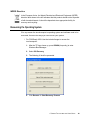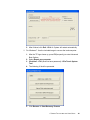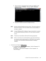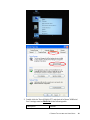
1
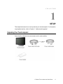
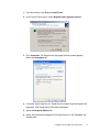
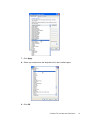
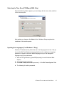
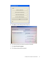
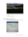
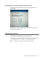
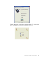
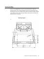
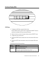
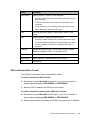
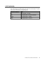
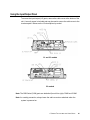
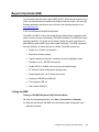
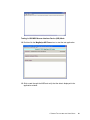
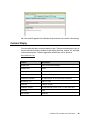
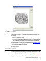
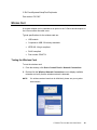
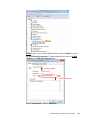
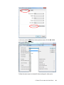
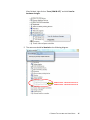
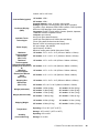
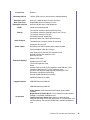
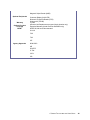
C-Series Touchcomputer User Guide C-Series LCD Multi-function Touchcomputer [19” and 22” model shown] TE Touch Solutions C-Series Touchcomputer User Guide Multi-function Touchcomputer Revision B P/N E826769 1-800-ELOTOUCH (1-800-356-8682) www.elotouch.com Copyright © 2011 Tyco Electronics Corporation. All Rights Reserved. No part of this publication may be reproduced, transmitted, transcribed, stored in a retrieval system, or translated into any language or computer language, in any form or by any means, including, but not limited to, electronic, magnetic, optical, chemical, manual, or otherwise without prior written permission of Tyco Electronics Corporation. Disclaimer The information in this document is subject to change without notice. Tyco Electronics Corporation and its Affiliates in the TE Touch Solutions business unit of the TE Connectivity Ltd. family of companies (collectively “TE”) makes no representations or warranties with respect to the contents hereof, and specifically disclaims any implied warranties of merchantability or fitness for a particular purpose. References in this publication to TE products or services do not imply that TE intends to make them available in all countries in which TE operates. TE reserves the right to revise this publication and to make changes from time to time in the content hereof without obligation of TE to notify any person of such revisions or changes. Trademark Acknowledgments AccuTouch, Elo TouchSystems, Elo TouchSystems (logo), Elo, IntelliTouch, iTouch, TE Connectivity, TE connectivity (logo) and TE (logo) are trademarks. Windows is a trademark of Microsoft Corporation. Other product names mentioned herein may be trademarks or registered trademarks of their respective companies. TE claims no interest in trademarks other than its own. C-SERIES TOUCHCOMPUTER USER GUIDE iii Table of Contents Chapter 1: Setup...................................................................................... 1 Unpacking Your Touchcomputer ....................................................................................................1 Adjusting the Display ......................................................................................................................2 Setting Up the Operating System.....................................................................................................2 Calibrating the Touchscreen ............................................................................................................9 Securing the Base...........................................................................................................................11 Chapter 2: Operation ............................................................................. 12 On-Screen Display (OSD) .............................................................................................................13 L.E.D. Functionality ......................................................................................................................15 Using the Input/Output Panel.........................................................................................................16 Chapter 3: Options and Upgrades ....................................................... 17 Adding Optional Peripherals..........................................................................................................17 Magnetic Stripe Reader (MSR) .....................................................................................................18 Customer Display...........................................................................................................................20 Fingerprint Reader (FPR) ..............................................................................................................21 Cash Drawer Port Card ..................................................................................................................22 Second VGA Port Card..................................................................................................................22 Wireless Card.................................................................................................................................23 Second Hard Disk Drive ................................................................................................................24 Solid State Drive ............................................................................................................................24 Modem Card ..................................................................................................................................24 Parallel Port Card...........................................................................................................................24 RAID Controller Card....................................................................................................................25 Webcam Kit ...................................................................................................................................25 Elo POS Demo Software ...............................................................................................................26 Chapter 4: Safety and Maintenance ..................................................... 27 Safety .............................................................................................................................................27 Care and Handling .........................................................................................................................28 Recovering the Operating System .................................................................................................29 C-SERIES TOUCHCOMPUTER USER GUIDE iv Chapter 5: Technical Specifications .................................................... 38 Touchcomputer Specifications.......................................................................................................38 Chapter 6: Technical Support............................................................... 43 Technical Assistance......................................................................................................................43 Regulatory Information............................................................................44 Warranty ...................................................................................................47 Index..........................................................................................................49 C-SERIES TOUCHCOMPUTER USER GUIDE v C H A P T E R 1 SETUP This chapter discusses how to set up and test your touchcomputer. For information on peripheral options, refer to Chapter 3, “Options and Upgrades.” Unpacking Your Touchcomputer Check that the following items are present and in good condition: C-SERIES TOUCHCOMPUTER USER GUIDE 1 Adjusting the Display The display screen can be adjusted from 0 to 70 degrees, as shown below. CAUTION: To prevent tipping or dropping, be sure to hold the base when adjusting the display. Setting Up the Operating System If configured with an operating system, the initial setup of the operating system takes approximately 5-10 minutes. Additional time may be needed depending on touchcomputer hardware configurations and connected devices. To set up the Microsoft® Windows® Operating System for the touchcomputer, turn on the touchcomputer by pressing the power button, and then follow the instructions on the screen. Selecting the Language (For POSReady 2009 Only) Microsoft Windows® uses English as the default language in menus and dialog boxes. You can change this language to suit your preferences at the screen below. Note: If you choose to change the language after initial setup, you can follow steps 1-2 to arrive at the same screen below: C-SERIES TOUCHCOMPUTER USER GUIDE 2 1. From the desktop, click Start > Control Panel 2. In the Control Panel screen, select Regional and Language Options. 3. Click Customize. The Regional and Language Options window appears. Select the Languages tab. 4. If required, check the boxes for “Install files for complex script and right-to-left languages” and “Install files for East Asian languages.” 5. Select the Regional Options tab. 6. Select your preferred language from the drop-down list in the Standards and formats pane. C-SERIES TOUCHCOMPUTER USER GUIDE 3 7. Click Apply. 8. Select your location from the drop-down list in the Locations pane. 9. Click OK. C-SERIES TOUCHCOMPUTER USER GUIDE 4 Selecting the Time Zone (POSReady 2009 Only) When the following window appears, you can change the time zone, date, and time of the touchcomputer. After making any changes, click Next to finish. Windows Setup completes the installation of the touchcomputer. Injecting the Languages (For Windows 7 Only) Windows 7 Professional only allows the use of one language at one time. But you can use the Elo TouchSystems language injection tool to update your language preference. English is set as the default language, but you can change this language to suit your preferences. 1. After the TE logo shows up, press F8 (frequently) to enter Advanced Boot Options. 2. Select Repair your computer. 3. Click Next OK (Shall not have password) Click Elo Touch System Tool. 4. The following UI shall be presented. C-SERIES TOUCHCOMPUTER USER GUIDE 5 5. Click Inject, and the following window will pop out. 6. Click the drop-down list and select the preference language. 7. Click Inject Selected Language 8. The following window shall be presented. C-SERIES TOUCHCOMPUTER USER GUIDE 6 9. After the language package is installed correctly, press any key to exit this window. 10. Click Exit Exit Restart Selecting the Region (For Windows 7 Only) When the following window appears, you can change the country, time and currency, and keyboard layout of the touchcomputer. After making any changes, click Next to continue. C-SERIES TOUCHCOMPUTER USER GUIDE 7 Choosing the Computer Name (For Windows 7 Only) When the following window appears, you can choose a computer name of the touchcomputer. After making any changes, click Next to continue. Selecting the Update Options (For Windows 7 Only) When the following window appears, you can select one of the update options of the touchcomputer. In general, you can choose Use recommended settings as your default option. After making any changes, click Next to continue. C-SERIES TOUCHCOMPUTER USER GUIDE 8 Reviewing the Time and Date Settings (For Windows 7 Only) When the following window appears, you can set up the time and date of the touchcomputer. After making any changes, click Next to finish. Windows Setup completes the installation of the touchcomputer. Calibrating the Touchscreen The touchscreen is pre-calibrated for accurate touch response. If for any reason the touchscreen needs to be recalibrated, right-click the Elo icon in the Taskbar and then click “Properties.” The following window opens. NOTE: Calibration is not applicable on APR touchscreen models. C-SERIES TOUCHCOMPUTER USER GUIDE 9 Click the Align button. This launches the calibration program. The window shown below opens. Follow the instructions to calibrate the touchscreen. C-SERIES TOUCHCOMPUTER USER GUIDE 10 Securing the Base Use the four pretapped holes to secure the touchcomputer from below the mounting surface. The holes are designed to work with ISO metric M4 screws. Mounting screws are not included with the product but should be readily available at any hardware store. Refer to the figure below for the location of the holes. All dimensions are in millimeters. Mounting Diagram 1) C-SERIES TOUCHCOMPUTER USER GUIDE 11 C H A P T E R 2 OPERATION This chapter describes how to control the On-Screen Display (OSD), power buttons, and I/O panel. All adjustments made to the OSD and power controls are automatically saved. User settings remain unchanged after powering off/on or in the case of a power failure. C-SERIES TOUCHCOMPUTER USER GUIDE 12 On-Screen Display (OSD) OSD Menu 1. To display the OSD Menu, press the Menu button. Press the RIGHT button or LEFT button to toggle and the SELECT button to select from the different OSD sub-menus and functions. 2. When the function you want to change is shown, press the SELECT button. 3. To adjust the value of the function: 4. Pressing the RIGHT button increases the value of the selected OSD control option. 5. Pressing the LEFT button decreases the value of the selected OSD control option. The OSD provides the following settings. Feature Description Auto adjust Automatically adjusts system clock. Brightness Adjust brightness and contrast. Brightness: Adjusts the backlight of the monitor. Contrast: Adjusts the maximum luminance level of the monitor. C-SERIES TOUCHCOMPUTER USER GUIDE 13 Feature Description Image setting Adjusts H position, V position, clock, and phase. H position: Moves the screen horizontally right and left (1 pixel pitch increment). V position: Moves the screen vertically up and down (1 line increment). Clock: Adjusts the ratio of dividing frequency of the dot clock. Phase: Adjusts the phase of the dot clock. Color Sets color temperature (9300K, 7500K, 6500K, 5500K, or User Preset). OSD Adjusts H position, V position, and OSD timeout. H position: Adjusts the OSD menu screen position left or right. V position: Adjusts the OSD menu screen position up or down. Timeout: Adjusts the amount of time that the OSD menu is displayed. Language Changes language to English, French, Italian, German, Spanish, Japanese, Simplified Chinese, or Traditional Chinese. Recall Sets color recall and recall defaults. Restores original factory settings. Miscellaneous Adjusts sharpness, enables/disables DDC/CI function. Exit Exits the OSD. OSD and Power Button Control The OSD menu and power button are enabled by default. To enable or disable the OSD function: 6. Simultaneously press Menu/Exit and the Left (<-) key for two seconds. A window appears displaying OSD ENABLE or OSD DISABLE. 7. When the OSD is disabled, the OSD menu is not visible. To enable or disable the power button (PWR) lock function: 8. Simultaneously press Menu/Exit and the Right (->) key for two seconds. A window appears displaying PWR ENABLE or PWR DISABLE. 9. When the power button lock feature is activated, the power button is disabled. C-SERIES TOUCHCOMPUTER USER GUIDE 14 L.E.D. Functionality The C-Series base has a LED indicating the state of the touchcomputer. The table below shows LED state and corresponding color. LED Color to Observer State Off No input power — Off mode Red Input power present – Off mode or hibernation Orange Input power present — Standby Green Input power present — Power On C-SERIES TOUCHCOMPUTER USER GUIDE 15 Using the Input/Output Panel To access the input/output (I/O) ports, remove the cable cover at the bottom of the unit. A security screw is included and may be used to secure the cable cover to the touchcomputer. Below are the I/O descriptions by model: C1 and C3 models C2 models Note: The DB9 Serial (COM) ports are defaulted (from left to right) COM5 and COM6 Note: As a safety precaution, always leave the cable cover door attached when the system is powered on. C-SERIES TOUCHCOMPUTER USER GUIDE 16 C H A P T E R 3 OPTIONS AND UPGRADES Adding Optional Peripherals When adding a peripheral, complete installation and setup instructions are provided with the field-installable kits. The following peripherals are available for purchase separately as field-installable kits: Magnetic stripe reader (MSR)* Customer display* Fingerprint reader (FPR)* Wireless adapter Cash Drawer Port Expansion Card Second VGA port expansion card** Second hard disk drive (HDD) Solid State Drive (SSD) RAID PCI-E*** Modem PCI-E*** Parallel Port PCI-E*** Webcam Kit * External Elo Peripheral ** Elo Expansion Card *** Elo PCI-E Expansion Card Note: Software drivers and applications for all peripherals are located in the C:\EloTouchSystems directory of the touchcomputer. Note: May install up to two (2) Elo Expansion Cards OR one (1) Elo Expansion Card + one (1) PCI-E Expansion Card C-SERIES TOUCHCOMPUTER USER GUIDE 17 Magnetic Stripe Reader (MSR) You can add a magnetic stripe reader (MSR) to the C-Series touchcomputer to any of the 4 mounting locations located on the display head top, bottom, left, and right. Software application and drivers can be found in the following directory or on www.elotouch.com C:\EloTouchSystems\SetupFiles\Peripherals The MSR is a USB 2.0 device that reads all three data stripes on standard credit cards or driver’s licenses conforming to ISO/ANSI standards. The MSR has foreign language capability. The credit card is read by sliding the credit card forward or backward through the MSR, stripe side toward the display. The MSR is powered from the USB port; no external power is needed. The MSR features are: Reads up to 3 tracks of information Bi-directional swipe reading Superior reading of high jitter, scratched, and worn MagStripe cards Reliable for over 1,000,000 card swipes Reads ISO7811, AAMVA, and most other card data formats PC software makes configuration changes easy Swipe speeds from 3 to 60 inches per second Interfaces: USB-KB and USB-HID Fully supports USB 2.0 Part number: E545781 Testing the MSR Testing in USB MSR Keyboard (KB) Emulation Mode 10. Open the Notepad application (click Start > Accessories > Notepad). 11. Slide the card through the MSR and verify that the data is displayed in the application window. C-SERIES TOUCHCOMPUTER USER GUIDE 18 Testing in USB MSR Human Interface Device (HID) Mode 12. Double-click the MagSwipe HID Demo icon to start the test application. 13. Slide a card through the MSR and verify that the data is displayed in the application window. C-SERIES TOUCHCOMPUTER USER GUIDE 19 14. If the card ID appears in the Reader Output window, the reader is functioning. Customer Display You can optionally add a customer display to the C-Series touchcomputer to any of the four mounting locations located on the display head top, bottom, left, and right of the touchcomputer. Software application and drivers can be found on www.elotouch.com Feature Description Display type Vacuum fluorescent display Display color Green Display pattern 5 x 7 dot matrix Brightness 350-600 cd/m2 Characters available 95 alphanumeric & 32 international characters Dot size (X x Y) 0.86 x 1.2 mm Font size 5.5(W) x 10.5(H) Character number 20 characters by 2 lines, for a 5 x 7 dot matrix font Interface USB Part number E879762 C-SERIES TOUCHCOMPUTER USER GUIDE 20 Fingerprint Reader (FPR) You can add a fingerprint reader to the C-Series touchcomputer to any of the four mounting locations located on the display head top, bottom, left, and right. Software application and drivers can be found in the following directory or on www.elotouch.com C:\EloTouchSystems\SetupFiles\Peripherals The fingerprint reader is powered by the USB bus. The reader optically scans the fingerprint when the user touches the glowing window. Optical technology gives the highest quality fingerprint scans and reliability. Fingerprint reader specifications are shown in the table below. Feature Specification Fingerprint reader DigitalPersona U.are.U Power supply 5.0VDC +/- 0.25V Current draw – scanning mode 190 mA (typical) Current draw – idle mode 140 mA (typical) Current draw – suspend mode 1.5 mA (typical) Image resolution 512 dpi Image color 8-bit gray level Scan capture size 14.6mm (nominal width) x 18.1mm (nominal length) Image capture speed 100 ms USB type 1.0, 1.1, or 2.0 Operating temperature 0 to 40°C Electrostatic discharge (ESD) Up to 15kV mounted in case Part number E375206 Testing the FPR 15. Double-click the Fingerprint Reader Test icon to start the test application. 16. Place your finger on the fingerprint reader sensor and verify that the image of your fingerprint is displayed on the application window. C-SERIES TOUCHCOMPUTER USER GUIDE 21 Cash Drawer Port Card A Cash Drawer Port Card can be installed in any available expansion slot. This card provides: 2 x 12V Powered USB ports 1 x 12V or 24V selectable cash drawer RJ11 port. The voltage setting can be set via jumper on the card prior to installing into the touchcomputer. Test applications can be found in the following directory or on www.elotouch.com : C:\EloTouchSystems\SetupFiles\Peripherals Part number: E318237 Second VGA Port Card A second VGA video card can be added to any available expansion slot. This card provides a VGA port to drive another VGA display. Software application and drivers can be found in the following directory or on www.elotouch.com C-SERIES TOUCHCOMPUTER USER GUIDE 22 C:\EloTouchSystems\SetupFiles\Peripherals Part number: E017487 Wireless Card A wireless adapter can be installed as an option in the C-Series touchcomputer in the I/O area under the cable cover. Typical specifications for the wireless card are: USB module Compliant to USB 2.0 industry standards IEEE 802.11b/g/n compliant RoHS compliant Part number: E249774 Testing the Wireless Card To test the wireless card: 1. From the desktop, click Start > Control Panel > Network Connections 2. Double-click the Wireless Network Connections icon to display available networks and verify that the wireless network is detected. NOTE: If a wireless network needs to be initialized, please see your system administrator. C-SERIES TOUCHCOMPUTER USER GUIDE 23 Second Hard Disk Drive A second hard disk drive can be added via the second hard drive mounting kit. This addition provides extra data storage or can be used in conjunction with the RAID controller card for RAID functionality. This option occupies a single expansion slot. Part number: E596876 Solid State Drive A solid state drive can be added to (or used to replace) the original hard disk drive. This addition provides additional performance and more mechanically reliability in harsh environments. Part number: E112963 Modem Card A modem card can be added to any expansion slot. This provides modem/fax functionality. Software drivers can be found in the following directory or on www.elotouch.com : C:\EloTouchSystems\SetupFiles\Peripherals Part number: E763313 Note: To use this option ALSO requires the purchase and installation of the Elo PCI-E Expansion Card Option Kit, part number E827958. Parallel Port Card A parallel port card can be added to any Expansion slot. This option provides a parallel port for printer interfaces only. Software drivers can be found in the following directory or on www.elotouch.com : C:\EloTouchSystems\SetupFiles\Peripherals Part number: E368899 Note: To use this option ALSO requires the purchase and installation of the Elo PCI-E Expansion Card Option Kit, part number E827958. C-SERIES TOUCHCOMPUTER USER GUIDE 24 RAID Controller Card A RAID controller card can be added when used in conjunction with a second HDD kit to provide RAID 0 and 1 functionality. Software drivers can be found in the following directory or on www.elotouch.com: C:\EloTouchSystems\SetupFiles\Peripherals Part number: E383216 Note: To use this option ALSO requires the purchase and installation of the Elo PCI-E Expansion Card Option Kit, part number E827958. Webcam Kit An integrated webcam kit with a built-in microphone is available for the C-Series touchcomputer. The Webcam module is a USB-powered device that includes a 2.0 megapixel camera, with stereo microphones built in. This webcam is capable of 2.0MP video at 5fps. This webcam can run on the drivers that are already preset in Windows Vista and Windows 7, and POSReady 2009. The built-in digital microphone for this webcam module is compliant with USB Audio Class 1.0. Webcam module specifications are shown in the table below: Feature 2.0MP Webcam w/2 x Digital Microphone USB Type Description MIT-AA20DA1 Video Resolution 1.0, 1.1 or 2.0 1600x1200, 1280x1024, 640x480, 352x388, 320x240, 176x144, 160x120 Auto Frame Rate 5fps max @ 2.0 megapixels (1600x1200); 24fps max @ VGA mode (640x480) Field Of View (FOV) 66° Focus Range 40cm ~ Infinity Input Voltage 5.0VDC ± 0.25V Operation Current Under 150mA Standby Mode 40mA ± 5mA Operating Temperature 0 to 40°C C-SERIES TOUCHCOMPUTER USER GUIDE 25 Supported Operating Systems Windows XP, Windows 7, Windows Vista, POSReady 2009 Part Number E682058 Elo POS Demo Software POS demo software created by Elo TouchSystems is located on the desktop in the Demos folder. C-SERIES TOUCHCOMPUTER USER GUIDE 26 C H A P T E R 4 SAFETY AND MAINTENANCE Safety Important information regarding the proper setup and maintenance of your touchcomputer: To reduce the risk of electric shock, follow all safety notices and never open the touchcomputer case. Turn off the product before cleaning (refer to “Care and Handling” on page 30 for proper cleaning methods). Your touchcomputer is equipped with a 3-wire, grounding power cord. The power cord plug only fits into a grounded outlet. Do not attempt to fit the plug into an outlet that has not been configured for this purpose. Do not use a damaged power cord. Only use the power cord that comes with your Elo TouchSystems touchcomputer. Use of an unauthorized power cord might invalidate your warranty. The slots located on the sides and top of the touchcomputer case are for ventilation. Do not block or insert anything inside the ventilation slots. It is important that your touchcomputer remains dry. Do not pour liquid into or onto your touchcomputer. If your touchcomputer becomes wet, do not attempt to repair it yourself. Contact Elo Customer Service for instructions. C-SERIES TOUCHCOMPUTER USER GUIDE 27 Care and Handling The following tips help keep your touchcomputer functioning at the optimal level. To avoid risk of electric shock, do not disassemble the power adapter or display unit cabinet. The unit is not user serviceable. Remember to unplug the display unit from the power outlet before cleaning. Do not use alcohol (methyl, ethyl, or isopropyl) or any strong solvent. Do not use thinner or benzene, abrasive cleaners, or compressed air. To clean the display unit cabinet, use a cloth lightly dampened with a mild detergent. Avoid getting liquids inside your touchcomputer. If liquid does get inside, have a qualified service technician check it before you power it on again. Do not wipe the screen with a cloth or sponge that could scratch the surface. To clean the touchscreen, use window or glass cleaner. Put the cleaner on the rag and wipe the touchscreen. Never apply the cleaner directly on the touchscreen. Warning This product consists of devices that might contain mercury, which must be recycled or disposed of in accordance with local, state, or federal laws. (Within this system, the backlight lamps in the monitor display contain mercury.) C-SERIES TOUCHCOMPUTER USER GUIDE 28 WEEE Directive In the European Union, the Waste Electrical and Electronic Equipment (WEEE) directive label shown to the left indicates that this product should not be disposed of with household waste. It should be deposited at an appropriate facility for recovery and recycling. Recovering the Operating System If for any reason the touchcomputer’s operating system and software need to be recovered, there are two ways you can recover your system: i. For POSReady 2009: Use the included image to recover the touchcomputer. 1. After the TE logo shows up, press DOWN (frequently) to enter Windows Boot Manager. 2. Select OS Recovery 3. The following UI shall be presented 4. Click Recover Start Recovery Process C-SERIES TOUCHCOMPUTER USER GUIDE 29 5. After finished, click Exit Exit System will restart automatically ii. For Windows 7: Use the included image to recover the touchcomputer. 1. After the TE logo shows up, press F8 (frequently) to enter Advanced Boot Options. 2. Select Repair your computer 3. Click Next OK (Shall not have password) Elo Touch System Tool 4. The following UI shall be presented 5. Click Recover Start Recovery Process C-SERIES TOUCHCOMPUTER USER GUIDE 30 6. After finished, click Exit Exit Restart iii. Use the recovery DVD to recover the touchcomputer. Recovery DVD’s can be ordered if necessary from TE Touch Solutions customer service. 1. Connect the USB DVD drive to the touchcomputer. 2. Place the recovery DVD in the DVD drive. 3. Press “F11” to enter Device Boot Menu and boot touchcomputer from DVD. 4. After entering the Elo Touch System Tool, click “WINPE” button. C-SERIES TOUCHCOMPUTER USER GUIDE 31 5. Once you see the “Command Prompt” window, type “win7” to start recovery process for Windows 7 and type “pos9” for Windows POSReady 2009. 6. Follow the on-screen instruction to complete recovery. NOTE: All data is deleted during the recovery process. The user must back up files when necessary. TE Touch Solutions does not accept liability for lost data or software. NOTE: If using POSReady 2009 or Windows 7 and your hard disk is corrupted, you can request a Recovery DVD from TE Touch Solutions customer service. NOTE: The end user must adhere to Microsoft's Licensing Agreement. NOTE: After you recovered your touchcomputer by using the included image, the operating system might reassign your USB Serial Ports during the first bootup. You can follow the instructions below to reassign it manually. Instructions to reassign the USB Serial Port 1. For POSReady 2009, right click the “Computer” Click “Properties” “Hardware” “Device Manager”. For Windows 7, right click the “Computer” Click “Properties” “Device Manager”. C-SERIES TOUCHCOMPUTER USER GUIDE 32 2. Double click the “Ports (COM & LPT)” and check all of these “USB Serial Port” settings must be IDENTICAL as the following table. Description Location C-SERIES TOUCHCOMPUTER USER GUIDE 33 USB Serial Port (COM3) USB Serial Port (COM4) On USB Serial Converter A On USB Serial Converter B 3. If you see a situation as below, it shows the operating system has reassigned these serial ports. You need to correct it manually. In usual, even if the operating system reassigns these serial ports, they are still in order. In this case, you should change it as the following table. Original one USB Serial Port (COM5) USB Serial Port (COM6) Change to USB Serial Port (COM3) USB Serial Port (COM4) Thus, the settings for these USB Serial Ports should begin at COM3 and end at COM4 in order. 4. To correct it, please follow the instructions below: Double click the port you need to change. In this case, it is COM5. C-SERIES TOUCHCOMPUTER USER GUIDE 34 COM5 is the 1st port of these USB serial ports so the “Location:” should be “on USB Serial Converter A”. Please assign this serial port to COM3. (COM4 for the USB Serial Converter B). Change to COM3 Location Information Select “Port Settings” Click “Advanced…” C-SERIES TOUCHCOMPUTER USER GUIDE 35 In this case, select COM3 from the drop‐down menu click OK OK back to the Device Manager. Follow the same steps to accomplish these settings for other ports. C-SERIES TOUCHCOMPUTER USER GUIDE 36 After finished, right click on “Ports (COM & LPT)” and click Scan for hardware changes. 5. The outcome should be identical as the following diagram. COM3 location: USB Serial Converter A COM4 location: USB Serial Converter B C-SERIES TOUCHCOMPUTER USER GUIDE 37 C H A P T E R 5 TECHNICAL SPECIFICATIONS Touchcomputer Specifications NOTE: Not all operating systems or options are supported in all regions. Please contact your local Elo TouchSystems representative for details. Feature C2 models Dark Grey or White Case/Bezel color 19” / 22” Screen Size Processor Chipset Video BIOS Memory (RAM) 800 MHz min C3 models 19” / 22” Intel 1.66GHz Atom Dual-Core D510 1MB L2 Cache 533MHz System Bus Intel NM10 Express Intel GMA 3150 6MB L2 Cache 1333MHz System Bus Intel G41 Express Intel GMA X4500 AMI AMI 2GB DDR2 DIMM on 1 of 2 slots (Expandable to 4GB maximum1 on 2 slots) 2GB DDR2 DIMM on 1 of 1 slot (Replaceable with 4GB maximum2 on 1 slot) Intel 3.0GHz Core 2 Duo E8400 2 1 Maximum memory using 2 slots. Expandable up to 4GB maximum, DIMM DDR2-800 (PC2-6400, dual channel). Maximum memory using 1 available slot; replacement for single, pre-installed memory module. Replaceable up to 4GB maximum, DIMM DDR2-800 (PC2-6400, dual channel). 160GB 2.5” SATA HDD3 Hard Disk Drive 3 GB equals one billion bytes when referring to storage capacity. Accessible capacity may be less. C-SERIES TOUCHCOMPUTER USER GUIDE 38 USB Ports Serial Ports Parallel Port PS/2 Ports Ethernet Port Wireless Cash Drawer Port Additional Ports Additional Video Out 6 x USB 2.0 (4 on I/O, 2 x USB Front Access) Additional internal ports available for optional Elo peripherals. 2 x USB-to-Serial RS-232 (standard) Optional parallel port card kit available N/A 1 x LAN RJ45 (Gigabit) Optional USB wireless kit availabile (802.11b/g/n) Optional cash drawer kit available (12V/24V default; selectable via jumper) See “Expansions & Upgrades” tab Standard HDMI out Optional 2nd VGA port expansion Optional 2nd VGA port card expansion card 1 x 3.5mm line in Audio Ports Speakers Operating System Options 1 x 3.5mm line out 1 x 3.5mm mic in Two 2W internal speakers No Operating System Microsoft Windows POSReady 2009 Microsoft Windows 7 Professional (32-bit only) Windows POSReady 2009 - 32 Language groups; Languages Display Aspect Ratio Useful Screen Area (H x V) Native (optimal) Resolution Colors Brightness (typical) Response Time (typical) Viewing Angle (typical) Windows 7 - 35 Language groups 19" models: 18.5" diagonal, active matrix TFT LCD 22" models: 21.5" diagonal, active matrix TFT LED LCD 19" models: 16:9 (standard) 22" models: 16:9 (standard) 19" models: 16.1" x 9.1" (409.8mm x 230.4mm) 22" models: 18.8" x 10.6"(476.6mm x 268.1mm) 19" models: 1366 x 768 @ 60Hz 22" models: 1920 x 1080 @ 60Hz 16.7 million LCD panel: 250 nits AccuTouch: 200 nits IntelliTouch Plus: 225 nits iTouch: 225 nits 19" models: Total: 5 msec 22" models: Total: 5 msec 19" models: Horizontal: ± 85° or 170° total Vertical: ±80° or 160° total 22" models: Horizontal: ± 85° or 170° total C-SERIES TOUCHCOMPUTER USER GUIDE 39 Vertical: ±80° or 160° total Contrast Ratio (typical) On-Screen Display (OSD) Available Touch Technologies Power Supply Maximum Touchcomputer Dimensions (W x H x D) Maximum Touchcomputer Dimensions With Stand (Display at 0° tilt, W x H x D) Maximum Touchcomputer Dimensions Without Stand (W x H x D) Shipping Box Dimensions (W x H x D) Weight (with stand) Weight (without stand) 19" models: 1000:1 22" models: 1000:1 Controls (bottom): menu, up, down, select, power Settings: brightness, contrast, phase, auto adjust, H-position, V-position, clock, sharpness, RGB, OSD H-position, OSD V-position, OSD time, OSD language, recall, power button Languages: English, French, Italian, German, Spanish, Japanese, Traditional Chinese, Simplified Chinese Lockouts: user controls AccuTouch (Zero-bezel Resistive) IntelliTouch Plus (Multi-touch Surface Acoustic Wave) iTouch (Zero-bezel Surface Acoustic Wave) External 12VDC universal-type power supply brick AC input voltage: 100-240VAC Input frequency: 50-60Hz Maximum output power: 240W (Max draw: 270W) 19" models: 18.7" x 14.2" x 12.4" (475mm x 360mm x 316mm) 22" models: 21.2" x 14.3" x 12.7" (540mm x 364mm x 323mm) 19" models: 18.7" x 14.9" x 8.9" (475mm x 380mm x 226mm) 22" models: 21.2" x 15.3" x 8.9" (540mm x 389mm x 226mm) 19" models: 18.7" x 11.9" x 3.8" (475mm x 302mm x 98mm) 22" models: 21.2" x 13.1" x 3.8" (540mm x 333mm x 98mm) 19" models: 23.2" x 19.5" x 14.2" (590mm x 495mm x 360mm) 22" models: 26" x 14.2" x 20.3" (660mm x 360mm x 516mm) 19" models: 19.5lbs (8.8kg) 22" models: 21.8lbs (9.9kg) 19" models: 13.7lbs (6.2kg) 19" models: 20.2lbs (9.2kg) 22" models: 21.8lbs (9.9kg) 19" models: 16.3lbs (7.4kg) 22" models: 17.9lbs (8.1kg) 22" models: 17.9lbs (8.1kg) 19" models: 30.3lbs (13.8kg) 19" models: 31.2lbs (14.2kg) 22" models: 33.4lbs (15.2kg) 22" models: 33.4lbs (15.2kg) Shipping Weight Temperature Humidity (non-condensing) Operating: 0°C to 35°C (32°F to 95°F) Storage: -30°C to 60°C (-22°F to 140°F) Operating: 20% to 80% Storage: 5% to 95% C-SERIES TOUCHCOMPUTER USER GUIDE 40 Form Factor Mounting Options Enclosure Color Real-Time Clock Backlight Lamp Life MTBF Sealing Other Features Power Cables Desktop 100mm VESA mount or secure base to tabletop/desktop Dark grey (*Medical/Japan versions are white) Replaceable lithium-ion battery for clock Minimum 50,000 hours to half brightness 50,000 hours demonstrated Touchscreen sealed to bezel (IntelliTouch Plus) Touchscreen sealed to sub-bezel (AccuTouch, iTouch) Touchscreen sealed to LCD (all) Serviceable internal components Removable base with 100mm VESA mounting Threaded holes on bottom of base for mounting Kensington security lock North American and European power cables included Wireless Adapter (USB, 802.11b/g/n) Cash Drawer Port (12V/24V) Elo expansion card Second VGA Port Elo expansion card RAID PCI-E Card1 Modem PCI-E Card1 Expansion Options Parallel Port PCI-E Card1 1 Elo PCI-E Expansion Card Notes: (a) May install up to two (2) Elo expansion cards OR one (1) Elo expansion card plus one (1) PCI-E expansion card. (b) Use of PCI-E option cards requires purchasing of PCI-E Expansion Card Option Kit E827958. Second 160GB Hard Disk Drive (HDD) 64GB Solid State Drive (SSD) Upgrade Options 2GB DDR2 Memory DIMM Kit 4GB DDR2 Memory DIMM Kit Accessories Power Cables: North American and European power cables included. Replacement DC Power Brick: 12V DC power brick, part number E409391, is available at additional cost. IntelliTouch/iTouch Stylus Pen: Stylus pen with rubber tip, designed specifically for use with IntelliTouch or iTouch surface wave touch technology. Part number D82064-000, available at additional cost. C-SERIES TOUCHCOMPUTER USER GUIDE 41 Magnetic Stripe Reader (MSR) Optional Peripherals Warranty Optional Product Coverage MTBF Customer Display (2x20 VFD) Biometric Fingerprint Reader (FPR) Webcam Kit (2.0 MP) 3 years Advance Unit Replacement program (North America only) Extended Warranty (North America and EMEA only) MTBF 50,000 hours demonstrated UL/cUL FCC TUV CE Agency Approvals NOM COC AR GOST-R C-Tick VCCI CB C-SERIES TOUCHCOMPUTER USER GUIDE 42 C H A P T E R 6 TECHNICAL SUPPORT Technical Assistance There are three methods to obtain contact information for technical assistance on the touchcomputer: The touchcomputer The web The phone Using the Touchcomputer You can access support information in System Properties by clicking the Support Information button. You can get to System Properties by either of the following methods: Right-click My Computer and choose Properties. OR Click the Start button, select Control Panel, and double-click the System icon. Using the Web For online self-help, go to www.elotouch.com/go/websupport. For technical support, go to www.elotouch.com/go/contactsupport. For current Elo news, product updates, and announcements, or to register to receive our Touchcomputer newsletter, go to www.elotouch.com/go/news. Using the Phone Call toll-free 1-800-ELO-TOUCH (1-800-356-8682). C-SERIES TOUCHCOMPUTER USER GUIDE 43 REGULATORY INFORMATION I. Electrical Safety Information A) Compliance is required with respect to the voltage, frequency, and current requirements indicated on the manufacturer’s label. Connection to a different power source than those specified herein may result in improper operation, damage to the equipment, invalidation of warranty, or a fire hazard if the requirements are not followed. B) There are no operator-serviceable parts inside this equipment. There are hazardous voltages generated by this equipment which constitute a safety hazard. Service should be provided only by a qualified service technician. C) This equipment is provided with a detachable power cord which has an integral safety ground wire intended for connection to a grounded safety outlet. 1) Do not substitute the cord with other than the provided approved type. Under no circumstances use an adapter plug to connect to a 2-wire outlet as this defeats the continuity of the grounding wire. 2) The equipment requires the use of the ground wire as a part of the safety certification. Modification or misuse can provide a shock hazard that can result in serious injury or death. 3) Contact a qualified electrician or the manufacturer if there are questions about the installation prior to connecting the equipment to main power. II. Emissions and Immunity Information A) Notice to Users in the United States: This equipment has been tested and found to comply with the limits for a Class A digital device, pursuant to Part 15 of FCC Rules. These limits are designed to provide reasonable protection against harmful interference in a residential or commercial installation. This equipment generates, uses, and can radiate radio frequency energy, and if not installed and used in accordance with the instructions, may cause harmful interference to radio communications. B) Notice to Users in Canada: This equipment complies with the Class A limits for radio noise emissions from digital apparatus as established by the Radio Interference Regulations of Industry Canada. C-SERIES TOUCHCOMPUTER USER GUIDE 44 C) Notice to Users in the European Union: Use only the provided power cords and interconnecting cabling provided with the equipment. Substitution of provided cords and cabling may compromise electrical safety or CE Mark Certification for emissions or immunity as required by the following standards: This Information Technology Equipment (ITE) is required to have a CE Mark on the manufacturer’s label which means that the equipment has been tested to the following Directives and Standards: This equipment has been tested to the requirements for the CE Mark as required by EMC Directive 2004/108/EC indicated in European Standard EN 55022 Class A and the Low Voltage Directive 2006/95/EC as indicated in European Standard EN 60950-1. D) General Information to all Users: This equipment generates, uses, and can radiate radio frequency energy. If not installed and used according to this manual, the equipment may cause interference with radio and television communications. There is, however, no guarantee that interference will not occur in any particular installation due to site-specific factors. 1) In order to meet emission and immunity requirements, the user must observe the following: a) Use only the provided I/O cables to connect this digital device with any computer. b) To ensure compliance, use only the provided manufacturer’s approved power cord. c) The user is cautioned that changes or modifications to the equipment not expressly approved by the party responsible for compliance could void the user’s authority to operate the equipment. 2) If this equipment appears to cause interference with radio or television reception, or any other device: a) Verify as an emission source by turning the equipment off and on. b) If you determine that this equipment is causing the interference, try to correct the interference by using one or more of the following measures: i) Move the digital device away from the affected receiver. ii) Reposition (turn) the digital device with respect to the affected receiver. iii) Reorient the affected receiver’s antenna. C-SERIES TOUCHCOMPUTER USER GUIDE 45 iv) Plug the digital device into a different AC outlet so the digital device and the receiver are on different branch circuits. v) Disconnect and remove any I/O cables that the digital device does not use. (Unterminated I/O cables are a potential source of high RF emission levels.) vi) Plug the digital device into only a grounded outlet receptacle. Do not use AC adapter plugs. (Removing or cutting the line cord ground may increase RF emission levels and may also present a lethal shock hazard to the user.) vii) If you need additional help, consult your dealer, manufacturer, or an experienced radio or television technician. III. Agency Certifications The following certifications have been issued for the monitor: Argentina S-Mark FCC Russia PCT Australia C-Tick IMERC WEEE CE Japan VCCI UL China CCC Mexico NOM cUL China RoHS TUV C-SERIES TOUCHCOMPUTER USER GUIDE 46 WARRANTY Except as otherwise stated herein or in an order acknowledgment delivered to Buyer, Seller warrants to Buyer that the Product shall be free of defects in materials and workmanship. With the exception of the negotiated warranty periods; the warranty for the touchcomputer and components of the product is 3 years. Seller makes no warranty regarding the model life of components. Seller’s suppliers may at any time and from time to time make changes in the components delivered as Products or components. Buyer shall notify Seller in writing promptly (and in no case later than thirty (30) days after discovery) of the failure of any Product to conform to the warranty set forth above; shall describe in commercially reasonable detail in such notice the symptoms associated with such failure; and shall provide to Seller the opportunity to inspect such Products as installed, if possible. The notice must be received by Seller during the Warranty Period for such product, unless otherwise directed in writing by the Seller. Within thirty (30) days after submitting such notice, Buyer shall package the allegedly defective Product in its original shipping carton(s) or a functional equivalent and shall ship to Seller at Buyer’s expense and risk. Within a reasonable time after receipt of the allegedly defective Product and verification by Seller that the Product fails to meet the warranty set forth above, Seller shall correct such failure by, at Seller’s options, either (i) modifying or repairing the Product or (ii) replacing the Product. Such modification, repair, or replacement and the return shipment of the Product with minimum insurance to Buyer shall be at Seller’s expense. Buyer shall bear the risk of loss or damage in transit, and may insure the Product. Buyer shall reimburse Seller for transportation cost incurred for Product returned but not found by Seller to be defective. Modification or repair, of Products may, at Seller’s option, take place either at Seller’s facilities or at Buyer’s premises. If Seller is unable to modify, repair, or replace a Product to conform to the warranty set forth above, then Seller shall, at Seller’s option, either refund to Buyer or credit to Buyer’s account the purchase price of the Product less depreciation calculated on a straight-line basis over Seller’s stated Warranty Period. C-SERIES TOUCHCOMPUTER USER GUIDE 47 THESE REMEDIES SHALL BE THE BUYER’S EXCLUSIVE REMEDIES FOR BREACH OF WARRANTY. EXCEPT FOR THE EXPRESS WARRANTY SET FORTH ABOVE, SELLER GRANTS NO OTHER WARRANTIES, EXPRESS OR IMPLIED BY STATUTE OR OTHERWISE, REGARDING THE PRODUCTS, THEIR FITNESS FOR ANY PURPOSE, THEIR QUALITY, THEIR MERCHANTABILITY, THEIR NONINFRINGEMENT, OR OTHERWISE. NO EMPLOYEE OF SELLER OR ANY OTHER PARTY IS AUTHORIZED TO MAKE ANY WARRANTY FOR THE GOODS OTHER THAN THE WARRANTY SET FORTH HEREIN. SELLER’S LIABILITY UNDER THE WARRANTY SHALL BE LIMITED TO A REFUND OF THE PURCHASE PRICE OF THE PRODUCT. IN NO EVENT SHALL SELLER BE LIABLE FOR THE COST OF PROCUREMENT OR INSTALLATION OF SUBSTITUTE GOODS BY BUYER OR FOR ANY SPECIAL, CONSEQUENTIAL, INDIRECT, OR INCIDENTAL DAMAGES. Buyer assumes the risk and agrees to indemnify Seller against and hold Seller harmless from all liability relating to (i) assessing the suitability for Buyer’s intended use of the Products and of any system design or drawing and (ii) determining the compliance of Buyer’s use of the Products with applicable laws, regulations, codes, and standards. Buyer retains and accepts full responsibility for all warranty and other claims relating to or arising from Buyer’s products, which include or incorporate Products or components manufactured or supplied by Seller. Buyer is solely responsible for any and all representations and warranties regarding the Products made or authorized by Buyer. Buyer will indemnify Seller and hold Seller harmless from any liability, claims, loss, cost, or expenses (including reasonable attorney’s fees) attributable to Buyer’s products or representations or warranties concerning same. C-SERIES TOUCHCOMPUTER USER GUIDE 48 INDEX address, Elo TouchSystems, 51 base power status, 15 base, securing, 11 box contents, 1 cables included, 1 calibration, 9 certifications, 46 contact information, 43 controls, location diagram, 12 customer display overview, 20 specifications, 20 customer support, 43 display screen adjusting, 2 email, Elo TouchSystems, 51 enabling or disabling power, 14 fingerprint reader (FPR) overview, 21 specifications, 21 testing, 21 input/output (I/O) panel accessing, 16 language selection, 2, 5 LCD adjusting, 2 LEDs base, 15 location diagram, 12 magnetic stripe reader (MSR) overview, 18 specifications, 18 testing, 18 maintenance care and handling, 27 software, 29 mounting options, 11 on-screen display (OSD) enabling or disabling menu, 14 menu settings, 13 operating system recovering, 29 setting up, 2 operation, 12 options, adding, 17 peripherals adding, 17 phone number, Elo TouchSystems, 43, 51 ports accessing, 16 power base, 15 enabling or disabling button lock, 14 regulatory information, 44 safety, 27 setup display screen, 2 language selection, 2, 5 mounting options, 11 operating system, 2 time zone selection, 5, 7, 8, 9 touchscreen calibration, 9 unpacking, 1 software demo, 26 recovery, 29 specifications customer display, 20 49 fingerprint reader, 21 magnetic stripe reader", 18 technical, 38 wireless card, 23 technical specifications, 38 technical support, 43 time zone selection, 5, 7, 8, 9 touchscreen calibrating, 9 care and handling, 28 upgrades, adding, 17 warranty, 47 website, Elo TouchSystems, 43, 51 WEEE directive, 29 wireless card overview, 23 specifications, 23 testing, 23 www.elotouch.com Get the latest... Product information Specifications News on upcoming events Press release Software drivers Touch Monitor Newsletter 50 Getting in Touch with Elo To find out more about Elo’s extensive range of touch solutions, visit our Website at www.elotouch.com or simply call the office nearest you: Europe Asia-Pacific Elo TouchSystems Sun Hamada Bldg. 2F 301 Constitution Drive Tyco Electronics Raychem B.V.B.A. Menlo Park, CA 94025 (Elo TouchSystems Division) Kanagawa 222-0033 USA Diestsesteenweg 692 Japan 1-19-20 ShinYokohama B-3010 Kessel-Lo Belgium (800) ELO-TOUCH Tel +81(45)478-2161 (800) 356-8682 Tel +32(0)(16)35 21 00 Fax +81(45)478-2180 Tel 650-361-4800 Fax +32(0)(16)35 21 01 www.tps.co.jp Fax 650-361-4747 [email protected] [email protected] © 2010 Tyco Electronics Printed in USA North America 51