1
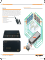
KD-CDA12P Operating Instructions
KD-CDA12P
12 Channel Component/RGBHV Video/Audio Distribution Amplifier
Operating Instructions
Key Digital™, led by digital video pioneer Mike Tsinberg,
develops and manufactures high quality, cutting-edge
technology solutions for virtually all applications where
high quality video imaging is important. Key Digital™
is at the forefront of the video industry for Home
Theater Retailers, Custom Installers, System Integrators,
Broadcasters, Manufacturers, and Consumers. We
provide total video system solutions because we
know and help drive the technology, the industry, the
business, and all the latest up-and-coming standards.
Xplosion Series™ KD-CDA12P is the perfect choice for high-quality and economical 12-channel
video and audio signal distribution from any HDTV or SDTV component video source, including
1080p. It delivers color-rich, artifact-free, and pristine HDTV and SDTV images to component
video (YPbPr) or RGBHV HDTV-ready monitors. KD-CDA12P is the ideal product for driving your
HD and SD sources to plasma displays, front and rear projectors, direct view monitors, and
video walls.
But most of all, we know exactly what you need for your
unique application - the right solution.
521 East 3rd Street, Mount Vernon, NY 10553
Phone :: 914.667.9700 Fax :: 914.668.8666
Web :: www.keydigital.com
KD-CDA12P_Manual.indd 2-1
Rev 0 – Sept 2006
9/29/06 11:16:01 AM
Page Page KD-CDA12P Operating Instructions
Important Safety Instructions.
Please be sure to follow these instructions
for safe operation of your unit
KD-CDA12P Operating Instructions
CAUTION!
KD-CDA12P HDTV Distribution Amplifier
12 Channel Component/RGBHV Video/Audio Distribution Amplifier
CAUTION: YOUR KD-CDA12P
HDTV DISTRIBUTION AMPLIFIER
COMES WITH ITS OWN EXTERNAL
POWER SUPPLY THAT MUST BE
ATTACHED TO THE UNIT.
1.
Read these instructions.
2.
Keep these instructions.
3.
Heed all warnings.
4.
Follow all instructions.
5.
Do not use this apparatus near water.
6.
Clean only with dry cloth.
7.
Do not block any ventilation openings. Install in
accordance with the manufacturer’s instructions.
8.
Do not install near any heat sources such as radiators, heat registers, stoves, or other
apparatus (including amplifiers) that produce heat.
9.
Do not defeat the safety purpose of the polarized or grounding-type plug. A polarized plug
has two blades with one wider than the other. A grounding type plug has two blades and
a third grounding prong. The wide blade or the third prong are provided for your safety. If
the provided plug does not fit into your outlet, consult an electrician for replacement of the
obsolete outlet.
Table of Contents
Introduction . . . . . . . . . . . . . . . . . . . . . . . . . . . . . . . . . . . . . . . . . . . . . . . . . . . . . . . . . . . . . . . . 2
Setting Up for Operation . . . . . . . . . . . . . . . . . . . . . . . . . . . . . . . . . . . . . . . . . . . . . . . . . . . . . . . 4
Configuration Modes . . . . . . . . . . . . . . . . . . . . . . . . . . . . . . . . . . . . . . . . . . . . . . . . . . . . . . . . . 5
No other Power Supply Adapter can be used with this unit!
Using a Power Supply other than the one provided by
Key Digital™ with your unit VOIDS THE ENTIRE PRODUCT
WARRANTY, may cause damage to your unit and
associated equipment, and is a potential safety hazard.
Troubleshooting . . . . . . . . . . . . . . . . . . . . . . . . . . . . . . . . . . . . . . . . . . . . . . . . . . . . . . . . . . . . . 6
You MUST use the Power
Supply that came with
your unit:
Technical Specifications . . . . . . . . . . . . . . . . . . . . . . . . . . . . . . . . . . . . . . . . . . . . . . . . . . . . . . . 8
Key Features for KD-CDA12P . . . . . . . . . . . . . . . . . . . . . . . . . . . . . . . . . . . . . . . . . . . . . . . . . . . 7
How to Contact Key Digital™ . . . . . . . . . . . . . . . . . . . . . . . . . . . . . . . . . . . . . . . . . . . . . . . . . . . . 9
10. Protect the power cord from being walked on or pinched particularly at plugs, convenience
receptacles, and the point where they exit from the apparatus.
11. Only use attachments/accessories specified by the manufacturer.
12. Use only with the cart, stand, tripod, bracket, or table specified by
the manufacturer, or sold with the apparatus. When a cart is used,
use caution when moving the cart/apparatus combination to avoid
injury from tip-over.
13. Unplug this apparatus during lightning storms or when unused for long periods of time.
14. Refer all servicing to qualified service personnel. Servicing is required when the apparatus
has been damaged in any way, such as power-supply cord or plug is damaged, liquid has
been spilled or objects have fallen into the apparatus, the apparatus has been exposed to rain
or moisture, does not operate normally, or has been dropped.
WARNING – To reduce the risk of fire or electric shock, do not expose his
apparatus to rain or moisture.
Apparatus shall not be exposed to dripping or splashing and no objects
filled with liquids, such as vases, shall be placed on the apparatus.
© 2006 Key Digital, Inc. All rights reserved.
KD-CDA12P_Manual.indd 2-1
9/29/06 11:16:05 AM
Page Page KD-CDA12P Operating Instructions
Introduction
KD-CDA12P Operating Instructions
Retail Environment Application
Key Digital™ dedication to providing the best possible solution to the Home Theater community
is reflected in the KD-CDA12P, manufactured with stringent quality control standards that exceed
the industry norm. This commitment to quality, reliability and performance is reflected throughout
the entire Key Digital™ product line. Every product is tested, and certified by a limited warranty of
two years parts and labor, one of the best in the business. Please read the installation instructions
below and enjoy your Component Video/Audio Distribution Amplifier for years to come.
Included in this package:
1.
2.
3.
4.
5.
(One) KD-CDA12P
(One) External power supply
(One) Power cord
(One) Set of installation/technical instructions
(One) Warranty Statement
Plasma/LCD
Plasma/LCD
Co
mp
one
nt
Co
mp
one
nt
Co
mp
one
nt
Aud
io
Aud
io
Aud
io
KD-CDA12P
Aud
io
Aud
io
Co
mp
one
nt
Co
mp
one
nt
Aud
io
Co
mp
one
nt
Co
Aud
mp
io
one
nt
Aud
io
HDTV Cable Box
Co
mp
one
nt
DVD Player
*All Component sources can
be substituted with RGBHV
KD-CDA12P_Manual.indd 2-3
9/29/06 11:16:36 AM
Page Page KD-CDA12P Operating Instructions
Setting Up for Operation
When unpacking the unit make all hookups and connections before plugging in the AC power
adapter.
This unit will accept virtually any component video input signal (Y, Pr, Pb) with a matching left and
right stereo audio pair (L/R audio can be substituted by a single digital PCM audio connection) and
distribute it to several “Display” devices around your home or showroom without the loss of signal.
A typical hookup will consist of a “Source” device that outputs component video (or S-Video with
an optional component video adapter) such as a DVD player, Set-Top Box unit, Satellite receiver,
digital VCR, Sony Playstation™, XBOX™, GameCube™ or any other consumer video device.
The “Source” device should be connected to the jacks marked “Input” on the KD-CDA12P. After
hooking up the “Source” device to the marked input connectors, the KD-CDA12P will distribute the
selected input signal to all of the output connectors. There are two banks (Marked Channel 1 and 2,
each corresponding to their respective inputs) of output connectors. Each of the RCA connectors
are color coded to match most “Source” and “Display” devices available in the consumer industry;
Red, Green and Blue for Component video; White, and Red for left and right audio respectively
(PCM audio can be distributed by using either the left or right audio channel).
Connecting your Unit
Typically, connecting the KD-CDA12P is as simple as matching the proper color coded connectors.
When inserting the RCA connectors use a slight twisting motion when inserting the cables, this
assures a proper connection by seating the RCA connector all the way in.
Be careful not to confuse the Red lead of a component video cable with the Right or Red audio
channel. Most often the audio wire is together with a White or Left audio lead! The Red lead from
the component video cable is often attached to the Green and Blue lead from the component
cable as well.
When running long lengths of cable please make sure to use heavy shielded high quality cables.
Now that the input(s) are connected, run each of the individual set of output connectors to their
respective “Display” devices. Make sure to use the correct wires when making the connections to
the “Display” device (use the color matching system if possible.)
Now that the installation is done it is recommended to double check all connections before
connecting the external power supply. Once every connection has been verified, plug the external
power supply connector into the power input jack of the KD-CDA12P. Once power has been
applied, a green light should show the power “ON” status on the front of the unit. Use a reliable
“Source” to test your connections (Like a DVD player).
KD-CDA12P Operating Instructions
Configuration Modes
The KD-CDA12P can be configured in 3 separate modes:
Set the slide switch to one of the following modes of operation.
1. Mode1: 2 inputs, each driving 6 outputs (this is the factory default mode)
2. Mode2: 1 input driving 12 outputs with the unused input driving the next distribution amplifier
3. Mode 3: 1 input driving 12 outputs
Mode 1:
Green LED on. The KD-CDA12P has two sets of inputs. This allows for independent connection
of two “Source” devices and usage of the KD-CDA12P as two separate KD-CDA6 units (these are
Key Digital™ 6-channel distribution amplifiers). Using this configuration it is possible to distribute two
discrete Audio/Video signals to two banks of 6 “Display” devices. This is the factory default mode.
Mode 2:
Green and Red LEDs on. The KD-CDA12P can also be cascaded or “Daisy Chained”. Using
this hookup method allows multiple units to be connected in series. One of the two inputs is for
receiving the Source or input signal; the other input is used for the “Loop-Through” signal, for
passing the input signal to the next amplifier in the chain of series. Either input can be used as
the “Source” input or as the “Loop-Through” input (to send the signal to the next KD-CDA12P or
KD-CDA6.) The Mode 2 setting is used for all KD-CDA12P units in the chain except for the last unit,
which must be set to Mode 3 (See below). A maximum of 4 KD-CDA12P can be connected in a
“Daisy Chain” using this hook-up method.
Mode 3:
Red LED on. The KD-CDA12P can be configured to distribute 1 input “Source” to 12 different
“Display” devices.
› Note: The factory default setting of the slide switch is Mode 1 (2x6 mode)!
Now that the installation is done it is recommended to double check all connections before
connecting the external power supply. Once every connection has been verified, plug the external
power supply connector into the power input jack of the KD-CDA12P or KD-CDA6. Once power
has been applied, a green light should show the power “ON” status on the front of the unit. Use a
reliable “Source” to test your connections (Like a DVD player).
Mounting and Maintenance instructions
The KD-CDA12P is built for years of trouble free operation. Cleaning or maintenance is usually not
necessary, but if needed use a soft non-abrasive dry cloth to wipe the dust from the unit.
Since the KD-CDA12P produces a small amount of heat, it is recommended to leave a few inches
of room around the unit to dissipate this heat.
KD-CDA12P_Manual.indd 4-5
9/29/06 11:16:39 AM
Page Page KD-CDA12P Operating Instructions
KD-CDA12P Operating Instructions
Troubleshooting
5.
a. This could happen when crossing power lines when routing the cable from the “Source”
device to the KD-CDA12P, or when routing the cables from the KD-CDA12P to the
“Display” device. If crossing power lines is inevitable, make sure to use heavy shielded high
quality cable. Sometimes using a shielded and noise filtering surge protector can eliminate
noise in power lines.
If the unit fails to properly distribute the “Source” signal even after all of the devices in the system
have been connected, the correct power supply has been connected, and the Source and Display
device(s) are known to be operational, try the following suggestions.
1.
6.
No power to the unit.
There is no signal displayed on the “Display” device.
a. Verify the Sync or Green connector on all of your video connections; make sure it is
connected to the correct input/output jack of the “Source” as well as the “Display” device.
b. Make sure that the “Source” can be displayed by the connected “Display” device; for
example: if the “Display” device connected to the output is not capable of handling HDTV
compatible video signals make sure that the “Source” device is set to output SD (Standard
definition or 480i) compatible signals.
3.
Key Features for KD-CDA12P
› Enables signal distribution any HDTV or SDTV Component Video source to Component Video
HDTV ready monitors
› Component Video Left and Right Analog Audio; Digital PCM audio can be used instead of the
Left and Right Analog Audio Signals
There is a signal but it is Black and White, Green or Pink in Nature.
› Can drive 12 monitors or two independent sets of 6 monitors.
a. This is indicative of a mismatch between “Source” and “Display” device in the component
video connections.
b. Make sure that the “Source” signal is of a valid format that can be displayed by the
connected “Display” device; for example: If the “Display” device connected cannot handle
HDTV compatible video signals make sure that the “Source” device is set output SD
(Standard Definition or 480i) compatible signals.
4.
I have No Audio.
a. When connecting the Left and Right (White and Red connector) stereo audio channel
make sure that the connectors are properly connected to the “Source” device as well as
the “Display” device.
b. Make sure that the volume is turned up to an audible level on the “Source” device as well
as the “Display” device.
c. When using the Digital Audio connection “PCM” or coaxial audio, make sure that the
“Display” device is capable of decoding this compressed bit stream of audio information.
Most often when using the “PCM” audio function, the audio will be connected to a Dolby
Digital® capable AV-Receiver or amplifier.
a. Make sure that the external power supply is properly connected to a standard household
outlet. Check to make sure the power indicator light is green. If there is no power light,
check and verify that the wall outlet is active by plugging in a known good component (like
a desk lamp). For added safety and protection it is always recommended to use a good
quality surge protector.
b. Check to make sure that the power connector is properly inserted into the KD-CDA12P.
c. Unplug the adapter from the wall and verify that the cable is not cut or interrupted
anywhere.
d. If none of the above works, please contact Key Digital™ technical support.
2.
I have a picture but there is noise or “hum bars” visible in the image.
› Can be configured for 3 modes (2x6, 1x12 terminated, 1x12 loop-through)
› RCA connectors for all video and audio inputs and outputs
› 300 MHz bandwidth
› Drives video signals up to 300 feet
› Can be cascaded to another KD-CDA12P to drive as many outputs as desired from one source
› External power supply
I have a picture but it is scrolling across the screen of my “Display”.
› Crystal clear image
a. This happens when the input signal is not compatible with the “Display” device. Make
sure that the “Source” signal is of a valid format that can be displayed by the connected
“Display” device; for example: if the “Display” device connected is not capable of handling
HDTV compatible video signals make sure that the “Source” device is set to output SD
(Standard Definition or 480i) compatible signals.
› Metal Enclosure
› Cost-effective
› 2 years parts and labor warranty
Key Digital Exclusive Technologies Key Digital Exclusive Technologies
®
KD-CDA12P_Manual.indd 6-7
®
9/29/06 11:16:40 AM
Page Page KD-CDA12P Operating Instructions
KD-CDA12P Operating Instructions
Technical Specifications
How to Contact Key Digital™
Model #: KD-CDA12P — 12 Channel Component/RGBHV Video/Audio Distribution Amplifier
Each input and output is comprised of five RCA connectors consisting of independent HDTV/SDTV
Component Video (YPrPb) plus two channels of audio L&R or PCM digital audio.
Repairs and Warranty Service
Video:
› Please contact us at either:
› Standard YPrPb 1 volt p-p 75 Ohm terminated Component Video.
Video bandwidth:
› - 3 dB @ 300 MHz.
Audio:
› Standard “line” type high impedance two-channel, Left & Right. Each L or R can be used for
PCM digital audio.
› Should your KD-CDA12P require warranty service, please contact Key Digital™ to obtain a
Returned Materials Authorization (RMA) number
➔
➔
Phone:
E-mail:
1-914-667-9700 ext 215
[email protected]
Technical Support
› For technical questions about using our products, please contact us at either:
➔
➔
Phone:
E-mail:
1-914-667-9700 ext 301
[email protected]
Cable Recommendation
› Each run of YPrPb cable MUST be the same length (300’ max.).
Customer Support
KD-CDA12P Characteristics:
› For customer support questions about using our products, please contact us at either:
› Size: 12-3/16” x 5-1/8” x 1-13/16” [310 x 130 x 46 mm] (case).
12-7/16” x 5-5/8” x 1-15/16” [316 x 143 x 49 mm] (with protruding jack/hardware).
› Weight: 3.5 lbs. (1.6 Kg.)
› Power: 6V / 5A, 110-120 VAC, 60Hz.
➔
No other power adapter can be used with this unit!
➔
➔
Phone:
E-mail:
1-914-667-9700 ext 223
[email protected]
Warranty
All Key Digital™ products are built to high manufacturing standards and should provide years of
trouble-free operation. They are backed by a limited two-year parts and labor warranty.
Orientation/Mounting Information:
› The top and bottom of the unit are solid metal (no vents).
› The unit may be oriented horizontally, or mounted vertically on a wall. Use 2 #8 or M4 screws to
hang the unit (keyhole slots are provided on the base of the unit). If installing into sheet-rock or
hollow walls, provide proper screw support with bolts or sheet-rock anchors.
› Limited Warranty: 2 years parts and labor.
KD-CDA12P_Manual.indd 8-9
9/29/06 11:16:44 AM