1
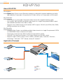
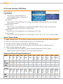
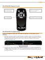
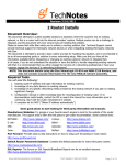
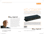
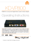
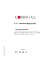
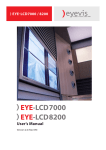
KD-VP750
Digital Video Processor, Switcher,
and Universal Video Center
Operating Instructions
KD-VP750
Key Digital’s KD-VP1250 and KD-VP750 are highly-flexible Universal Video Centers with
video processing and video switching abilities. These Hot Rod Series™ Video Processors
are capable of scaling, de-interlacing, up-converting, and down-converting virtually any input
source and output to virtually any Standard and High Definition display up to 1080p.
Page 2
Table of Contents
KD-VP750
About KD-VP750 . . . . . . . . . . . . . . . . . . . . . . . . . . . . . . . . . . . . . . . . . . . . . . . . . . . . . . . . . . . . 6
Application Example . . . . . . . . . . . . . . . . . . . . . . . . . . . . . . . . . . . . . . . . . . . . . . . . . . . . . . . . . . 6
Connections, LEDs and Button Map . . . . . . . . . . . . . . . . . . . . . . . . . . . . . . . . . . . . . . . . . . . . . . 7
On Screen Display (OSD) Map . . . . . . . . . . . . . . . . . . . . . . . . . . . . . . . . . . . . . . . . . . . . . . . . . . 8
Quick Setup Guide . . . . . . . . . . . . . . . . . . . . . . . . . . . . . . . . . . . . . . . . . . . . . . . . . . . . . . . . . . . 8
Supported Input/Output Resolutions . . . . . . . . . . . . . . . . . . . . . . . . . . . . . . . . . . . . . . . . . . . . . 8
RS-232 Commands and Protocol . . . . . . . . . . . . . . . . . . . . . . . . . . . . . . . . . . . . . . . . . . . . . . . . 9
Specifications . . . . . . . . . . . . . . . . . . . . . . . . . . . . . . . . . . . . . . . . . . . . . . . . . . . . . . . . . . . . . . 10
KD-VP1250/750 Remote Control . . . . . . . . . . . . . . . . . . . . . . . . . . . . . . . . . . . . . . . . . . . . . . . . 11
KD-VP1250/750 Troubleshooting . . . . . . . . . . . . . . . . . . . . . . . . . . . . . . . . . . . . . . . . . . . . . . . . 11
Important Product Warnings & Safety Instructions . . . . . . . . . . . . . . . . . . . . . . . . . . . . . . . . . . . 12
How to Contact Key Digital® . . . . . . . . . . . . . . . . . . . . . . . . . . . . . . . . . . . . . . . . . . . . . . . . . . . 13
Warranty Information . . . . . . . . . . . . . . . . . . . . . . . . . . . . . . . . . . . . . . . . . . . . . . . . . . . . . . . . . 13
Please read all instructions to insure safe operation of the product.
© 2010 Key Digital, Inc. All rights reserved.
Page 6
KD-VP750
About KD-VP750
Description
»» Digital Video Processor and Switcher capable of scaling 480i standard definition and 480p
high definition Component, Composite and S-Video sources to Component or VGA output.
Key Features
»» VGA Output accommodate Component Video format with supplied breakout cable
»» Up-converts 480i and 480p resolution video inputs to a single Component/RGBHV output
with available resolutions from 480i to 1080p
»» Supports most video formats to all standard HDTV outputs: SD, HD, and VESA (VGA, SXGA,
WXGA) resolutions up to 1080p
Key Benefits
»» Universal Video Center consolidating multiple video formats to a single Componenent/YPrPb
or VGA/RGBHV Video connection on display
»» Frame rate conversion from 50Hz to 60Hz and from 60Hz to 50Hz
»» Optical IR, Top panel push buttons, On-Screen Display and RS-232 control.
»» Supports major control systems such as AMX®, Colorado vNet®, Control4®, Crestron®,
HomeLogic™, lifeIware™, RTI®, Savant, Universal®, Xantech®
Application Example
Comp
KD-VP750
Optical IR
DVD Player
RS232 Control
OR
Plasma TV
Comp
Security Cam
CV
HDMI/DVI
Component
S-Video
VCR
VGA
Composite (CV)
S-Video
VGA
Monitor
Page 7
Connections, LEDs and Button Map
Front
LED Lights
Output Resolution LEDs
Indicate current Output Resolution selected
IR Eye
Buttons
Menu / Left Button
Up Button
Down Button
Select / Right Button
Output Resolution Button
Enter Menu, Go Back,
or Navigate Left through
the On Screen Display
Navigate Up
through the On
Screen Display
Navigate Down
through the On
Screen Display
Choose, go Forward, or
navigate Right through
the On Screen Display
Cycle through the available
Output Resolutions
Rear
Outputs
VGA/YPrPb
Analog Video Output for VGA/RGBHV or
Component/YPrPb video format. Use
supplied three-wire breakout cable for
Component/YPrPb Output.
Unit Connections
Power Connection
Operation Switch
Switch to “Program”
when upgrading
firmware
CV / Y
Used for Y Channel of
Component/YPrPb Video
source or Composite
Video Input
RS-232 Port
S-Video
S-Video standard
definition source
Input
Pb
Pr
Inputs
Page 8
On Screen Display (OSD) Map
Set Up Menu
½½ Input Source
»» Press the Up or Down Buttons to
½½
½½
½½
½½
cycle through S-Video, Composite, or
Component Inputs
Out Resolut.
»» Press the Up or Down Buttons to cycle through available output resolutions and available
frame rates for each
Analog Output
»» Press the Up or Down Buttons to cycle between RGBHV (VGA) or YPbPr (Component)
output video format for the VGA / YPrPb Output
Aspect Ratio
»» Press the Up or Down Buttons to cycle between 4:3 or 16:9
Over Scanning
»» Press the Up or Down Buttons to cycle through Off, 20%, 15%, 10%, or 5% Over Scanning
Quick Setup Guide
1. Begin with the KD-VP750 and all input/output devices turned off with power cables removed
2. Connect video sources to appropriate input ports on the KD-VP750
3. Connect all video outputs to displays or receiving devices
4. Connect power to the KD-VP750 and all other input/output devices and turn them on
5. Select desired Analog Video Mode
»» Use supplied three-wire breakout cable if selecting Component/YPrPb Output
»» Select desired output resolution by pressing Output Resolution
Supported Input/Output Resolutions
INPUT
480i
/60
576i
/50
CV
4
4
S-Video
4
4
YPrPb
4
OUTPUT 480i
/60
480p
/60
576p
/50
4
4
4
576i
/50
480p
/60
VGA
YPrPb
4
4
720p
50&60
1080i
50&60
VGA
640x
480
SVGA
800x
600
XGA
1024x
768
SXGA
1280x
1024
WXGA
1366x
768
1080p
50&60
576p
/50
720p
50&60
1080i
50&60
VGA
640x
480
SVGA
800x
600
XGA
1024x
768
SXGA
1280x
1024
WXGA
1366x
768
1080p
50&60
4
4
4
4
4
4
4
4
4
4
4
4
4
Page 9
RS-232 Commands and Protocol
½½ KD-VP750 is compatible with all Control Systems, such as AMX®, Colorado vNet®, Control4®,
Crestron®, HomeLogic™, lifeIware™, RTI®, Savant, Universal®, Xantech®
½½ Connect your Control System’s Master Controller to the KD-VP750 unit using the RS-232 port.
Follow all instructions provided with your control system.
»» RS-232 Protocol:
»»
Baud Rate = 19600 bits per second
»»
Data Bits = 8
»»
Parity = None
»»
Stop Bits = 1
»»
Flow Control = None
»»
RS-232 Command List:
RS-232 Command List:
RS-232 Command
Description
Comments
H
Help
Full RS-232 command listing
SP O R x y
Set Output
Resolution
System Output Setup Commands
x = Format, y = Frame Rate
x= [1=480i/576i, 2=480p/576p,
3=SVGA, 4=XGA, 5=1360x768p,
6=SXGA, 7=720p, 8=1080i, 9=1080p]
y = [1=60hz, 2=50hz]
*Note: Computer resolutions always output @ 60hz
irrelevant to setting of “y”.
SP O A x
Set analog output
x = [1=RGBHV, 2=Component]
SP O S x
Set aspect ratio
x = [1=4:3, 2=16:9]
SP O V x
Set overscan
x = [1=off, 2=5%, 3=10%, 4=15%, 5=20%]
SP I x
Input Select
x = [1=CVBS, 2=S-Video, 3=Component]
System Control Setup Commands
SP C FB E/D/T
Front Panel Buttons
Enabled/Disabled/
Toggle
SP C DF
Reset to Factory
Defaults
E = Enable, D = Disable, T = Toggle
Status Commands
ST A
Out Global System
Status
Page 10
Specifications
Technical:
»» Inputs: 1x Component (Y, Pb, Pr) 1Vpp/75Ω (progressive or interlaced) on RCA Connectors;
1x Composite 1Vpp/75Ω on RCA connector, 1x S-Video 1Vpp/75Ω (Y)
»» Outputs: 1 x Component/RGBHV Scaled output (Y/G, Pb/B, Pr/R, H, V) 1Vpp/75Ω; 5V TTL
for H&V on a VGA female connector
»» Processing: 8 fields of 3-D motion adaptive de-interlacing; 3:2 and 2:2 pull-down; bad-edit
film detection and correction; subtitle detection and artifact removal; pixel-by-pixel adaptive
interpolation; intra-inter-interpolation with alpha-blend combination; multi-directional edge
detection and interpolation; fast moving detection and interpolation; noise detection and
noise adaptive interpolation; anti-aliasing filter for down scaling, independent vertical and
horizontal filter for up and down scaling
»» Control: Front panel push buttons, front IR, On Screen Display, RS-232 control
»» Additional Control: Auto sensing for input resolutions, selectable output resolutions,
independent ProcAmp and aspect ratio control
»» Power: External 6V/5A power supply for 100-240VAC, 50/60Hz, 30VA.
General:
»» Regulation:RoHS, WEEE
»» Rack Mount: Half Rack (Rack Ears Included)
»» Enclosure: Black Metal
»» Product Dimensions: L = 8.25” W = 4.25” H = 1.75”
»» Shipping Carton Dimensions: L = 13.5” W = 7” H = 4.5”
»» Product Weight: 2 lbs
»» Shipping Weight: 3 lbs
»» Accessories: IR Remote Control, VGA (F) to RCA (F) Breakout Cable,
UL Certified Power Supply
Page 11
KD-VP1250/750 Remote Control
R1 Button
R1
Menu
Toggle analog output mode
between YPrPb and RGBHV
Menu Button
Enter OSD menu / Exit OSD menu /
Move one step backward
Select
Select Button
Arrow Buttons
Select current OSD item
Use arrow buttons to navigate through OSD
www.keydigital.com
KD-VP1250/750 Troubleshooting
If you use component output from KD-VP1250/750 and don’t see any picture, try the
following:
1. Set output resolution to 480i or 480p (European customers should set it to 576i or 576p) by
pressing ‘Output Resolution’ button on the front of the unit.. Keep in mind that if LED doesn’t
change after pressing ‘Output Resolution’ button, frame rate changed to 50hz with the
resolution remaining same.
KD-VP1250
Output Resolution Button
KD-VP750
2. If you still don’t see any picture after changing resolution, press R1 button on the remote to
change analog output mode to YPbPr. This is required because if the KD-VP1250/750 is set
to RGBHV output, component sync is not available on the output, resulting in the display not
showing any picture.
Page 12
Important Product Warnings:
1. Connect all cables before providing power to the unit.
2. Test for proper operation before securing unit behind walls or in hard to access spaces.
3. If installing the unit into wall or mounting bracket into sheet-rock, provide proper screw support
with bolts or sheet-rock anchors.
Safety Instructions.
Please be sure to follow these instructions for safe operation of your unit.
1. Read and follow all instructions.
2. Heed all warnings.
3. Do not use this device near water.
4. Clean only with dry cloth.
5. Install in accordance with the manufacturer’s instructions.
6. Do not install near any heat sources such as radiators, heat registers, stoves, or other
apparatus (including amplifiers) that produce heat.
7. Only use attachments/accessories specified by the manufacturer.
8. Refer all servicing to qualified service personnel. Servicing is required when the device has
been damaged in any way including:
»» Damage to the power supply or power plug
»» Exposure to rain or moisture
You MUST use the Power Supply provided with your unit or you VOID
the Key Digital® Warranty and risk damage to your unit and associated equipment.
Page 13
How to Contact Key Digital®
System Design Group (SDG)
For system design questions please contact us at:
½½ Phone:914-667-9700
½½ E-mail:[email protected]
Key Digital Trainings
For questions about Key Digital® Trainings please contact us at:
½½ Phone:914-667-9700
½½ E-mail:[email protected]
Customer Support
For customer support questions please contact us at:
½½ Phone:914-667-9700
½½ E-mail:[email protected]
Technical Support
For technical questions about using Key Digital® products, please contact us at:
½½ Phone:914-667-9700
½½ E-mail: [email protected]
Marketing and Public Relations:
For marketing and public relations information, please contact us at:
½½ Phone:914-667-9700
½½ E-mail:[email protected]
Repairs and Warranty Service
Should your product require warranty service or repair, please obtain a Key Digital® Return Material
Authorization (RMA) number by contacting us at:
½½ Phone:914-667-9700
½½ E-mail:[email protected]
Feedback
Please email any comments/questions about the manual to:
½½ E-mail:[email protected]
Warranty Information
All Key Digital® products are built to high manufacturing standards and should provide years of
trouble-free operation. They are backed by a limited two-year parts and labor warranty.
Key Digital®, led by digital video pioneer Mike Tsinberg,
develops and manufactures high quality, cutting-edge
technology solutions for virtually all applications where
high quality video imaging is important. Key Digital®
is at the forefront of the video industry for Home
Theater Retailers, Custom Installers, System Integrators,
Broadcasters, Manufacturers, and Consumers. We
provide total video system solutions because we
know and help drive the technology, the industry, the
business, and all the latest up-and-coming standards.
But most of all, we know exactly what you need for your
unique application - the right solution.
521 East 3rd Street, Mount Vernon, NY 10553
Phone :: 914.667.9700 Fax :: 914.668.8666
Web :: www.keydigital.com
Rev 0 – Mar. 2010