1
Environmental Investigations
Standard Operating Procedures
and
Quality Assurance Manual
NOVEMBER 2001
U.S. Environmental Protection Agency
Region 4
980 College Station Road
Athens, Georgia 30605-2720
www.epa.gov/region4/sesd/eisopqam/eisopqam.html
**(706) 355-8603**
EISOPQAM
TABLE of CONTENTS
SECTION 1 - Preface . . . . . . . . . . . . . . . . . . . . . . . . . . . . . . . . . . . . . . . . . . . . . . . . . . . . . .
1.1
Introduction . . . . . . . . . . . . . . . . . . . . . . . . . . . . . . . . . . . . . . . . . . . . . . . . . . . . . .
1.2
Performance Objectives . . . . . . . . . . . . . . . . . . . . . . . . . . . . . . . . . . . . . . . . . . . .
1.3
Section Objectives . . . . . . . . . . . . . . . . . . . . . . . . . . . . . . . . . . . . . . . . . . . . . . . . .
1-1
1-1
1-1
1-1
SECTION 2 - Investigations, Inspections, and Overview Activities . . . . . . . . . . . . . . . . . 2 - 1
2.1
Introduction . . . . . . . . . . . . . . . . . . . . . . . . . . . . . . . . . . . . . . . . . . . . . . . . . . . . . . 2 - 1
2.2
Potable Water Supply Investigations . . . . . . . . . . . . . . . . . . . . . . . . . . . . . . . . . 2 - 1
2.3
Civil Enforcement Investigations and Studies . . . . . . . . . . . . . . . . . . . . . . . . . . 2 - 2
2.3.1
Introduction . . . . . . . . . . . . . . . . . . . . . . . . . . . . . . . . . . . . . . . . . . . . . . . . . . . . . . . 2 - 2
2.3.2
Facility Entry . . . . . . . . . . . . . . . . . . . . . . . . . . . . . . . . . . . . . . . . . . . . . . . . . . . . . . 2 - 3
2.3.3
Unreasonable Search and Seizure . . . . . . . . . . . . . . . . . . . . . . . . . . . . . . . . . . . . . . 2 - 4
2.3.4
Requesting Information . . . . . . . . . . . . . . . . . . . . . . . . . . . . . . . . . . . . . . . . . . . . . . 2 - 5
2.3.5
Photographs . . . . . . . . . . . . . . . . . . . . . . . . . . . . . . . . . . . . . . . . . . . . . . . . . . . . . . . 2 - 5
2.3.6
Split Samples . . . . . . . . . . . . . . . . . . . . . . . . . . . . . . . . . . . . . . . . . . . . . . . . . . . . . . 2 - 6
2.4
Criminal Investigations and Studies . . . . . . . . . . . . . . . . . . . . . . . . . . . . . . . . . . 2 - 6
2.5
Clean Water Act Compliance Monitoring Inspections . . . . . . . . . . . . . . . . . . . 2 - 7
2.5.1
Introduction . . . . . . . . . . . . . . . . . . . . . . . . . . . . . . . . . . . . . . . . . . . . . . . . . . . . . . . 2 - 7
2.5.2
CWA Inspection Types . . . . . . . . . . . . . . . . . . . . . . . . . . . . . . . . . . . . . . . . . . . . . . 2 - 7
2.5.3
Study Plans . . . . . . . . . . . . . . . . . . . . . . . . . . . . . . . . . . . . . . . . . . . . . . . . . . . . . . 2 -09
2.5.4
NPDES Compliance Inspection Reports . . . . . . . . . . . . . . . . . . . . . . . . . . . . . . . . 2 -10
2.6
Superfund Investigations, Technical Assistance, and Overview Activities . . 2 -11
2.6.1
Introduction . . . . . . . . . . . . . . . . . . . . . . . . . . . . . . . . . . . . . . . . . . . . . . . . . . . . . . 2 -11
2.6.2
Superfund Investigation Types . . . . . . . . . . . . . . . . . . . . . . . . . . . . . . . . . . . . . . . 2 -11
2.6.3
Planning for Field Investigative Support . . . . . . . . . . . . . . . . . . . . . . . . . . . . . . . 2 -11
2.6.4
Requests for Superfund Studies . . . . . . . . . . . . . . . . . . . . . . . . . . . . . . . . . . . . . . 2 -12
2.6.5
Investigation Study Plans . . . . . . . . . . . . . . . . . . . . . . . . . . . . . . . . . . . . . . . . . . . 2 -12
2.6.6
Investigation Reports . . . . . . . . . . . . . . . . . . . . . . . . . . . . . . . . . . . . . . . . . . . . . . . 2 -13
2.7
RCRA Inspections, Investigations, and Overview Activities . . . . . . . . . . . . . 2 -14
2.7.1
Introduction . . . . . . . . . . . . . . . . . . . . . . . . . . . . . . . . . . . . . . . . . . . . . . . . . . . . . . 2 -14
2.7.2
RCRA Investigation Types . . . . . . . . . . . . . . . . . . . . . . . . . . . . . . . . . . . . . . . . . . 2 -14
2.7.3
Planning for Field Investigative Support . . . . . . . . . . . . . . . . . . . . . . . . . . . . . . . 2 -15
2.7.4
Requests for RCRA Studies . . . . . . . . . . . . . . . . . . . . . . . . . . . . . . . . . . . . . . . . . 2 -15
2.7.5
Investigation Study Plans . . . . . . . . . . . . . . . . . . . . . . . . . . . . . . . . . . . . . . . . . . . 2 -15
2.7.6
Investigation Reports . . . . . . . . . . . . . . . . . . . . . . . . . . . . . . . . . . . . . . . . . . . . . . . 2 -15
2.8
Underground Storage Tank (UST) Investigations . . . . . . . . . . . . . . . . . . . . . . 2 -16
2.8.1
Introduction . . . . . . . . . . . . . . . . . . . . . . . . . . . . . . . . . . . . . . . . . . . . . . . . . . . . . . 2 -16
2.8.2
Investigation Study Plans . . . . . . . . . . . . . . . . . . . . . . . . . . . . . . . . . . . . . . . . . . . 2 -17
2.8.3
Investigation Reports . . . . . . . . . . . . . . . . . . . . . . . . . . . . . . . . . . . . . . . . . . . . . . . 2 -17
2.9
Underground Injection Control (UIC) Investigations . . . . . . . . . . . . . . . . . . . 2 -18
2.9.1
Introduction . . . . . . . . . . . . . . . . . . . . . . . . . . . . . . . . . . . . . . . . . . . . . . . . . . . . . . 2 -18
2.9.2
Investigation Study Plans . . . . . . . . . . . . . . . . . . . . . . . . . . . . . . . . . . . . . . . . . . . 2 -18
2.9.3
Investigation Reports . . . . . . . . . . . . . . . . . . . . . . . . . . . . . . . . . . . . . . . . . . . . . . . 2 -19
2.10
Ambient Air Monitoring Evaluations and Audits . . . . . . . . . . . . . . . . . . . . . . 2 -19
EISOPQAM
ToC - i
November 2001
EISOPQAM
TABLE of CONTENTS
2.10.1
2.10.2
2.10.3
2.10.4
2.10.5
2.10.6
2.10.7
2.11
Introduction . . . . . . . . . . . . . . . . . . . . . . . . . . . . . . . . . . . . . . . . . . . . . . . . . . . . . . 2 -19
NAMS/SLAMS Site Evaluations . . . . . . . . . . . . . . . . . . . . . . . . . . . . . . . . . . . . . 2 -19
Table 2.10.1 - Guidelines for PM10 and SO2 NAMS Network Size . . . . . . . . . . . 2 -21
Table 2.10.2 - Population Levels for which NAMS Monitoring of
Pollutants other than PM10 and SO2 is Required . . . . . . . . . . . . . . . . . . . . . . . . . . 2 -22
Table 2.10.3 - Summary of Spatial Scales Usually Needed for SLAMS & NAMS 2 -22
Table 2.10.4 - Summary of Probe Siting Criteria . . . . . . . . . . . . . . . . . . . . . . . . . 2 -24
Table 2.10.5 - Minimum Distance between Sampling Probe and Roadways . . . . 2 -25
State and Local QA Plan Reviews . . . . . . . . . . . . . . . . . . . . . . . . . . . . . . . . . . . 2 -26
Performance Audits . . . . . . . . . . . . . . . . . . . . . . . . . . . . . . . . . . . . . . . . . . . . . . 2 -26
Air Monitoring Technical System Audit . . . . . . . . . . . . . . . . . . . . . . . . . . . . . 2 -28
National Performance Audit Program . . . . . . . . . . . . . . . . . . . . . . . . . . . . . . . 2 -29
PM2.5 Federal Reference Method (FRM) Performance Audit Program (PEP).. 2 -30
References . . . . . . . . . . . . . . . . . . . . . . . . . . . . . . . . . . . . . . . . . . . . . . . . . . . . . . . 2 -32
Exhibit 2.1 - Hazardous Waste Field Overview Checklist . . . . . . . . . . . . . . . . . . 2 -33
Exhibit 2.2 - State Contractor Overview Checklist . . . . . . . . . . . . . . . . . . . . . . . . 2 -48
Exhibit 2.3 - State Program Evaluation - Hazardous Waste Field Activities . . . . 2 -51
SECTION 3 - Sample Control, Field Records, and Document Control . . . . . . . . . . . . . . 3 - 1
3.1
Introduction . . . . . . . . . . . . . . . . . . . . . . . . . . . . . . . . . . . . . . . . . . . . . . . . . . . . . . 3 - 1
3.2
Sample and Evidence Identification . . . . . . . . . . . . . . . . . . . . . . . . . . . . . . . . . . 3 - 2
3.2.1
Sample Identification . . . . . . . . . . . . . . . . . . . . . . . . . . . . . . . . . . . . . . . . . . . . . . . 3 - 2
3.2.2
Photograph, Digital, Image, and Video Identification . . . . . . . . . . . . . . . . . . . . . . 3 - 3
3.2.3
Identification of Physical Evidence . . . . . . . . . . . . . . . . . . . . . . . . . . . . . . . . . . . . . 3 - 3
3.3
Chain-of-Custody Procedures . . . . . . . . . . . . . . . . . . . . . . . . . . . . . . . . . . . . . . . 3 - 4
3.3.1
Introduction . . . . . . . . . . . . . . . . . . . . . . . . . . . . . . . . . . . . . . . . . . . . . . . . . . . . . . . 3 - 4
3.3.2
Sample Custody . . . . . . . . . . . . . . . . . . . . . . . . . . . . . . . . . . . . . . . . . . . . . . . . . . . 3 - 4
3.3.3
Documentation of Chain-of-Custody . . . . . . . . . . . . . . . . . . . . . . . . . . . . . . . . . . . 3 - 5
3.3.4
Transfer of Custody with Shipment . . . . . . . . . . . . . . . . . . . . . . . . . . . . . . . . . . . . 3 - 6
3.4
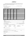
Receipt for Samples Form (CERCLA/RCRA/TSCA) . . . . . . . . . . . . . . . . . . . . 3 - 7
3.4.1
Introduction . . . . . . . . . . . . . . . . . . . . . . . . . . . . . . . . . . . . . . . . . . . . . . . . . . . . . . . 3 - 7
3.4.2
Receipt for Samples Form . . . . . . . . . . . . . . . . . . . . . . . . . . . . . . . . . . . . . . . . . . . . 3 - 7
3.5
Field Records . . . . . . . . . . . . . . . . . . . . . . . . . . . . . . . . . . . . . . . . . . . . . . . . . . . . . 3 - 8
3.6
Document Control . . . . . . . . . . . . . . . . . . . . . . . . . . . . . . . . . . . . . . . . . . . . . . . . . 3 - 9
3.7
Disposal of Samples or Other Physical Evidence . . . . . . . . . . . . . . . . . . . . . . . 3 -10
3.8
Field Operations Records Management System (FORMS) . . . . . . . . . . . . . . 3 -10
Figure 3-1 - Chain-of Custody Form . . . . . . . . . . . . . . . . . . . . . . . . . . . . . . . . . . . 3 -11
Figure 3-2 - Media Codes . . . . . . . . . . . . . . . . . . . . . . . . . . . . . . . . . . . . . . . . . . . 3 -12
Figure 3-3 - Sample Tag . . . . . . . . . . . . . . . . . . . . . . . . . . . . . . . . . . . . . . . . . . . . 3 -13
Figure 3-4 - Receipt for Samples Form . . . . . . . . . . . . . . . . . . . . . . . . . . . . . . . . . 3 -14
Figure 3-5- EPA Custody Seal . . . . . . . . . . . . . . . . . . . . . . . . . . . . . . . . . . . . . . . 3 -15
SECTION 4 - Branch Safety Protocols . . . . . . . . . . . . . . . . . . . . . . . . . . . . . . . . . . . . . . . . 4 - 1
EISOPQAM
ToC - ii
November 2001
EISOPQAM
TABLE of CONTENTS
4.1
4.2
4.2.1
4.2.2
4.2.3
4.2.4
4.2.5
4.3
4.3.1
4.3.2
4.3.3
4.3.4
4.3.5
4.3.6
4.3.7
4.3.8
Introduction . . . . . . . . . . . . . . . . . . . . . . . . . . . . . . . . . . . . . . . . . . . . . . . . . . . . . . 4 - 1
Hazard Communication Procedure . . . . . . . . . . . . . . . . . . . . . . . . . . . . . . . . . . . 4 - 2
Introduction . . . . . . . . . . . . . . . . . . . . . . . . . . . . . . . . . . . . . . . . . . . . . . . . . . . . . . . 4 - 2
Scope . . . . . . . . . . . . . . . . . . . . . . . . . . . . . . . . . . . . . . . . . . . . . . . . . . . . . . . . . . . . 4 - 2
Labels and Other Forms of Warnings . . . . . . . . . . . . . . . . . . . . . . . . . . . . . . . . . . . 4 - 2
Material Safety Data Sheets (MSDSs) . . . . . . . . . . . . . . . . . . . . . . . . . . . . . . . . . . 4 - 3
The Hazard Chemical Inventory . . . . . . . . . . . . . . . . . . . . . . . . . . . . . . . . . . . . . . . 4 - 4
Safety Protocols . . . . . . . . . . . . . . . . . . . . . . . . . . . . . . . . . . . . . . . . . . . . . . . . . . . 4 - 5
Site Safety Officer Duties . . . . . . . . . . . . . . . . . . . . . . . . . . . . . . . . . . . . . . . . . . . . 4 - 5
Safety Equipment . . . . . . . . . . . . . . . . . . . . . . . . . . . . . . . . . . . . . . . . . . . . . . . . . . 4 - 6
OSHA Confined Space Entry . . . . . . . . . . . . . . . . . . . . . . . . . . . . . . . . . . . . . . . . . 4 - 6
Entry into Enclosed Areas . . . . . . . . . . . . . . . . . . . . . . . . . . . . . . . . . . . . . . . . . . . . 4 - 6
Training Status Tracking System . . . . . . . . . . . . . . . . . . . . . . . . . . . . . . . . . . . . . . 4 - 7
Site Operations . . . . . . . . . . . . . . . . . . . . . . . . . . . . . . . . . . . . . . . . . . . . . . . . . . . . 4 - 7
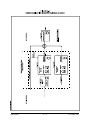
Figure 4-1 - Decontamination Zone for Levels A and B . . . . . . . . . . . . . . . . . . . . 4 -19
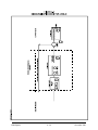
Figure 4-2 - Decontamination Zone for Level C . . . . . . . . . . . . . . . . . . . . . . . . . 4 -20
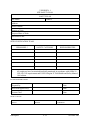
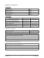
Exhibit 4.1 - Site Safety Plan . . . . . . . . . . . . . . . . . . . . . . . . . . . . . . . . . . . . . . . . 4 -22
Boating Operations . . . . . . . . . . . . . . . . . . . . . . . . . . . . . . . . . . . . . . . . . . . . . . . . 4 -27
Exhibit 4.2 - Float Plan . . . . . . . . . . . . . . . . . . . . . . . . . . . . . . . . . . . . . . . . . . . . 4 -29
Field Procedures for Handling Pathogenic Samples . . . . . . . . . . . . . . . . . . . . . . . 4 -30
SECTION 5 - Sampling Design and Quality Assurance Procedures . . . . . . . . . . . . . . . . 5 - 1
5.1
Introduction . . . . . . . . . . . . . . . . . . . . . . . . . . . . . . . . . . . . . . . . . . . . . . . . . . . . . . 5 - 1
5.2
Definitions . . . . . . . . . . . . . . . . . . . . . . . . . . . . . . . . . . . . . . . . . . . . . . . . . . . . . . . 5 - 1
5.3
Sampling Design . . . . . . . . . . . . . . . . . . . . . . . . . . . . . . . . . . . . . . . . . . . . . . . . . . 5 - 5
5.3.1
Introduction . . . . . . . . . . . . . . . . . . . . . . . . . . . . . . . . . . . . . . . . . . . . . . . . . . . . . . . 5 - 5
5.3.2
Representative Sampling . . . . . . . . . . . . . . . . . . . . . . . . . . . . . . . . . . . . . . . . . . . . . 5 - 5
5.3.3
Stratification and Heterogeneous Wastes . . . . . . . . . . . . . . . . . . . . . . . . . . . . . . . . 5 - 5
5.3.4
Specific Sampling Designs . . . . . . . . . . . . . . . . . . . . . . . . . . . . . . . . . . . . . . . . . . . 5 - 6
5.3.5
Determining the Number of Samples to Collect . . . . . . . . . . . . . . . . . . . . . . . . . . . 5 - 6
5.3.6
Authoritative or Directed Sampling . . . . . . . . . . . . . . . . . . . . . . . . . . . . . . . . . . . . 5 - 6
5.3.7
Simple Random Sampling . . . . . . . . . . . . . . . . . . . . . . . . . . . . . . . . . . . . . . . . . . . 5 - 6
5.3.8
Systematic Sampling over Time or Space . . . . . . . . . . . . . . . . . . . . . . . . . . . . . . . . 5 - 7
5.3.9
Stratified Random Sampling . . . . . . . . . . . . . . . . . . . . . . . . . . . . . . . . . . . . . . . . . . 5 - 7
5.3.10
Systematic Grid Sampling . . . . . . . . . . . . . . . . . . . . . . . . . . . . . . . . . . . . . . . . . . . . 5 - 7
5.3.11
Adaptive Cluster Sampling . . . . . . . . . . . . . . . . . . . . . . . . . . . . . . . . . . . . . . . . . . 5 - 7
5.4
General Considerations for Sampling Designs . . . . . . . . . . . . . . . . . . . . . . . . . . 5 - 8
5.5
Soil Sampling Designs . . . . . . . . . . . . . . . . . . . . . . . . . . . . . . . . . . . . . . . . . . . . . . 5 - 9
5.5.1
Historical Sampling Data, Site Survey, and Site History . . . . . . . . . . . . . . . . . . . . 5 - 9
5.5.2
Data Quality Objectives (DQOs) . . . . . . . . . . . . . . . . . . . . . . . . . . . . . . . . . . . . . . 5 - 9
5.5.3
Authoritative Designs for Soil Investigations . . . . . . . . . . . . . . . . . . . . . . . . . . . . . 5 - 9
5.5.4
Systematic Grid Sampling Designs for Soil Investigations . . . . . . . . . . . . . . . . . 5 -10
5.6
Ground Water Sampling Designs . . . . . . . . . . . . . . . . . . . . . . . . . . . . . . . . . . . 5 -14
5.6.1
Single Source Iterative Programs . . . . . . . . . . . . . . . . . . . . . . . . . . . . . . . . . . . . . 5 -14
EISOPQAM
ToC - iii
November 2001
EISOPQAM
TABLE of CONTENTS
5.6.2
5.6.3
5.7
5.7.1
5.7.2
5.7.3
5.7.4
5.7.5
5.8
5.8.1
5.8.2
5.8.3
5.8.4
5.8.5
5.9
5.10
5.11
5.12
5.13
5.13.1
5.13.2
5.13.3
5.13.4
5.13.5
5.13.6
5.13.7
5.13.8
5.13.9
5.13.10
5.13.11
5.13.12
5.13.13
5.14
5.14.1
5.14.2
5.14.3
5.15
5.15.1
5.15.2
5.15.3
5.16
Multiple-Source Area Grided Programs . . . . . . . . . . . . . . . . . . . . . . . . . . . . . . . .
Typical Ground Water Screening Devices . . . . . . . . . . . . . . . . . . . . . . . . . . . . . .
Surface Water and Sediment Sampling Designs . . . . . . . . . . . . . . . . . . . . . . .
Sampling Site Selection . . . . . . . . . . . . . . . . . . . . . . . . . . . . . . . . . . . . . . . . . . . .
Rivers, Streams, and Creeks . . . . . . . . . . . . . . . . . . . . . . . . . . . . . . . . . . . . . . . . .
Lakes, Ponds, and Impoundments . . . . . . . . . . . . . . . . . . . . . . . . . . . . . . . . . . . . .
Estuarine Waters . . . . . . . . . . . . . . . . . . . . . . . . . . . . . . . . . . . . . . . . . . . . . . . . . .
Control Stations . . . . . . . . . . . . . . . . . . . . . . . . . . . . . . . . . . . . . . . . . . . . . . . . . . .
Waste Sampling Designs . . . . . . . . . . . . . . . . . . . . . . . . . . . . . . . . . . . . . . . . . . .
Introduction . . . . . . . . . . . . . . . . . . . . . . . . . . . . . . . . . . . . . . . . . . . . . . . . . . . . . .
Waste Investigation Objectives . . . . . . . . . . . . . . . . . . . . . . . . . . . . . . . . . . . . . . .
Considerations for Waste Sampling Designs . . . . . . . . . . . . . . . . . . . . . . . . . . . .
Waste Sampling Equipment . . . . . . . . . . . . . . . . . . . . . . . . . . . . . . . . . . . . . . . . .
Field Screening . . . . . . . . . . . . . . . . . . . . . . . . . . . . . . . . . . . . . . . . . . . . . . . . . . .
Figure 5-1 - RCRA Waste Characterization Flow Chart . . . . . . . . . . . . . . . . . . .
Wastewater Sampling Designs . . . . . . . . . . . . . . . . . . . . . . . . . . . . . . . . . . . . . .
UST and UIC Sampling Designs . . . . . . . . . . . . . . . . . . . . . . . . . . . . . . . . . . . .
Air Toxics Monitoring Designs . . . . . . . . . . . . . . . . . . . . . . . . . . . . . . . . . . . . .
Data Quality Objectives . . . . . . . . . . . . . . . . . . . . . . . . . . . . . . . . . . . . . . . . . . .
Specific Sample Collection Quality Control Procedures . . . . . . . . . . . . . . . . .
Introduction . . . . . . . . . . . . . . . . . . . . . . . . . . . . . . . . . . . . . . . . . . . . . . . . . . . . . .
Experience Requirements . . . . . . . . . . . . . . . . . . . . . . . . . . . . . . . . . . . . . . . . . . .
Traceability Requirements . . . . . . . . . . . . . . . . . . . . . . . . . . . . . . . . . . . . . . . . . .
Chain-of-Custody . . . . . . . . . . . . . . . . . . . . . . . . . . . . . . . . . . . . . . . . . . . . . . . . .
Sampling Equipment Construction Material . . . . . . . . . . . . . . . . . . . . . . . . . . . . .
Sample Preservation . . . . . . . . . . . . . . . . . . . . . . . . . . . . . . . . . . . . . . . . . . . . . . .
Special Precautions for Trace Contaminant Sampling . . . . . . . . . . . . . . . . . . . . .
Sample Handling and Mixing . . . . . . . . . . . . . . . . . . . . . . . . . . . . . . . . . . . . . . . .
Special Handling of Samples for Volatile Organic Compounds (VOCs) Analysis
Estimating Variability . . . . . . . . . . . . . . . . . . . . . . . . . . . . . . . . . . . . . . . . . . . . . .
Special Quality Control Procedures for Water Samples for Extractable
Organic Compounds, Pesticides, or Herbicides Analysis (Matrix Duplicate) . . .
Special Quality Control Procedures for EPA Contract Laboratories . . . . . . . . . .
Special Quality Control Procedures for Dioxins and Furans . . . . . . . . . . . . . . . .
Internal Quality Control Procedures . . . . . . . . . . . . . . . . . . . . . . . . . . . . . . . .
Introduction . . . . . . . . . . . . . . . . . . . . . . . . . . . . . . . . . . . . . . . . . . . . . . . . . . . . . .
Traceability Requirements . . . . . . . . . . . . . . . . . . . . . . . . . . . . . . . . . . . . . . . . . .
Specific Quality Control Checks . . . . . . . . . . . . . . . . . . . . . . . . . . . . . . . . . . . . . .
Investigation Derived Waste (IDW) . . . . . . . . . . . . . . . . . . . . . . . . . . . . . . . . .
Types of IDW . . . . . . . . . . . . . . . . . . . . . . . . . . . . . . . . . . . . . . . . . . . . . . . . . . . .
Management of Non-Hazardous IDW . . . . . . . . . . . . . . . . . . . . . . . . . . . . . . . . .
Management of Hazardous IDW . . . . . . . . . . . . . . . . . . . . . . . . . . . . . . . . . . . . . .
Table 5.15.1 - Disposal of IDW . . . . . . . . . . . . . . . . . . . . . . . . . . . . . . . . . . . . . .
References . . . . . . . . . . . . . . . . . . . . . . . . . . . . . . . . . . . . . . . . . . . . . . . . . . . . . .
EISOPQAM
ToC - iv
5 -15
5 -15
5 -16
5 -16
5 -17
5 -19
5 -20
5 -21
5 -21
5 -21
5 -22
5 -22
5 -23
5 -23
5 -25
5 -26
5 -27
5 -27
5 -28
5 -31
5 -31
5 -31
5 -31
5 -32
5 -32
5 -32
5 -32
5 -33
5 -34
5 -34
5 -36
5 -36
5 -37
5 -37
5 -37
5 -37
5 -38
5 -38
5 -38
5 -39
5 -39
5 -41
5 -42
November 2001
EISOPQAM
TABLE of CONTENTS
SECTION 6 - Design and Installation of Monitoring Wells . . . . . . . . . . . . . . . . . . . . . . . 6 - 1
6.1
Introduction . . . . . . . . . . . . . . . . . . . . . . . . . . . . . . . . . . . . . . . . . . . . . . . . . . . . . . 6 - 1
6.2
Permanent Monitoring Wells - Design Considerations . . . . . . . . . . . . . . . . . . . 6 - 1
6.3
Drilling Methods . . . . . . . . . . . . . . . . . . . . . . . . . . . . . . . . . . . . . . . . . . . . . . . . . . 6 - 2
6.3.1
Hollow-Stem Auger . . . . . . . . . . . . . . . . . . . . . . . . . . . . . . . . . . . . . . . . . . . . . . . . 6 - 2
6.3.2
Solid-Stem Auger . . . . . . . . . . . . . . . . . . . . . . . . . . . . . . . . . . . . . . . . . . . . . . . . . . 6 - 2
6.3.3
Sonic Methods . . . . . . . . . . . . . . . . . . . . . . . . . . . . . . . . . . . . . . . . . . . . . . . . . . . . . 6 - 3
6.3.4
Rotary Methods . . . . . . . . . . . . . . . . . . . . . . . . . . . . . . . . . . . . . . . . . . . . . . . . . . . . 6 - 3
6.3.5
Other Methods . . . . . . . . . . . . . . . . . . . . . . . . . . . . . . . . . . . . . . . . . . . . . . . . . . . . . 6 - 4
6.4
Borehole Construction . . . . . . . . . . . . . . . . . . . . . . . . . . . . . . . . . . . . . . . . . . . . . 6 - 5
6.4.1
Annular Space . . . . . . . . . . . . . . . . . . . . . . . . . . . . . . . . . . . . . . . . . . . . . . . . . . . . . 6 - 5
6.4.2
Overdrilling the Borehole . . . . . . . . . . . . . . . . . . . . . . . . . . . . . . . . . . . . . . . . . . . . 6 - 5
6.4.3
Filter Pack Placement . . . . . . . . . . . . . . . . . . . . . . . . . . . . . . . . . . . . . . . . . . . . . . . 6 - 5
6.4.4
Filter Pack Seal-Bentonite Pellet Seal (Plug) . . . . . . . . . . . . . . . . . . . . . . . . . . . . . 6 - 5
6.4.5
Grouting the Annular Space . . . . . . . . . . . . . . . . . . . . . . . . . . . . . . . . . . . . . . . . . . 6 - 6
6.4.6
Above Ground Riser Pipe and Outer Protective Casing . . . . . . . . . . . . . . . . . . . . . 6 - 6
6.4.7
Concrete Surface Pad . . . . . . . . . . . . . . . . . . . . . . . . . . . . . . . . . . . . . . . . . . . . . . . 6 - 7
6.4.8
Surface Protection-Bumper Guards . . . . . . . . . . . . . . . . . . . . . . . . . . . . . . . . . . . . 6 - 7
6.5
Construction Techniques . . . . . . . . . . . . . . . . . . . . . . . . . . . . . . . . . . . . . . . . . . . 6 - 7
6.5.1
Well Installation . . . . . . . . . . . . . . . . . . . . . . . . . . . . . . . . . . . . . . . . . . . . . . . . . . . 6 - 7
6.5.2
Double Cased Wells . . . . . . . . . . . . . . . . . . . . . . . . . . . . . . . . . . . . . . . . . . . . . . . . 6 - 9
6.6
Well Construction Materials . . . . . . . . . . . . . . . . . . . . . . . . . . . . . . . . . . . . . . . 6 -10
6.6.1
Introduction . . . . . . . . . . . . . . . . . . . . . . . . . . . . . . . . . . . . . . . . . . . . . . . . . . . . . . 6 -10
6.6.2
Well Screen and Casing Materials . . . . . . . . . . . . . . . . . . . . . . . . . . . . . . . . . . . . 6 -10
6.6.3
Filter Pack Materials . . . . . . . . . . . . . . . . . . . . . . . . . . . . . . . . . . . . . . . . . . . . . . . 6 -11
6.6.4
Filter Pack and Well Screen Design . . . . . . . . . . . . . . . . . . . . . . . . . . . . . . . . . . . 6 -11
6.7
Safety Procedures for Drilling Activities . . . . . . . . . . . . . . . . . . . . . . . . . . . . . 6 -12
6.8
Well Development . . . . . . . . . . . . . . . . . . . . . . . . . . . . . . . . . . . . . . . . . . . . . . . . 6 -14
6.9
Well Abandonment . . . . . . . . . . . . . . . . . . . . . . . . . . . . . . . . . . . . . . . . . . . . . . . 6 -15
6.9.1
Abandonment Procedures . . . . . . . . . . . . . . . . . . . . . . . . . . . . . . . . . . . . . . . . . . . 6 -15
6.10
Temporary Monitoring Well Installation . . . . . . . . . . . . . . . . . . . . . . . . . . . . . 6 -16
6.10.1
Introduction . . . . . . . . . . . . . . . . . . . . . . . . . . . . . . . . . . . . . . . . . . . . . . . . . . . . . . 6 -16
6.10.2
Data Limitation . . . . . . . . . . . . . . . . . . . . . . . . . . . . . . . . . . . . . . . . . . . . . . . . . . . 6 -17
6.10.3
Temporary Well Materials . . . . . . . . . . . . . . . . . . . . . . . . . . . . . . . . . . . . . . . . . . 6 -17
6.10.4
Temporary Monitoring Well Borehole Construction . . . . . . . . . . . . . . . . . . . . . . 6 -17
6.10.5
Temporary Monitoring Well Types . . . . . . . . . . . . . . . . . . . . . . . . . . . . . . . . . . . 6 -17
6.10.6
Backfilling . . . . . . . . . . . . . . . . . . . . . . . . . . . . . . . . . . . . . . . . . . . . . . . . . . . . . . . 6 -18
6.11
Temporary Monitoring Well Installation Using Geoprobe® Screen Point 15
Groundwater Sampler . . . . . . . . . . . . . . . . . . . . . . . . . . . . . . . . . . . . . . . . . . . . 6 -19
6.11.1
Introduction . . . . . . . . . . . . . . . . . . . . . . . . . . . . . . . . . . . . . . . . . . . . . . . . . . . . . 6 -19
6.11.2
Assembly of Screen Point 15 Groundwater Sampler . . . . . . . . . . . . . . . . . . . . . . 6 -19
6.11.3
Installation of Screen Point 15 Groundwater Sampler . . . . . . . . . . . . . . . . . . . . . 6 -19
6.11.4
Special Considerations for Screen Point 15 Installations . . . . . . . . . . . . . . . . . . . 6 -20
6.12
References . . . . . . . . . . . . . . . . . . . . . . . . . . . . . . . . . . . . . . . . . . . . . . . . . . . . . . 6 -21
EISOPQAM
ToC - v
November 2001
EISOPQAM
TABLE of CONTENTS
SECTION 7 - Ground Water Sampling . . . . . . . . . . . . . . . . . . . . . . . . . . . . . . . . . . . . . . . . 7 - 1
7.1
Introduction . . . . . . . . . . . . . . . . . . . . . . . . . . . . . . . . . . . . . . . . . . . . . . . . . . . . . . 7 - 1
7.2
Purging . . . . . . . . . . . . . . . . . . . . . . . . . . . . . . . . . . . . . . . . . . . . . . . . . . . . . . . . . . 7 - 1
7.2.1
Purging and Purge Adequacy . . . . . . . . . . . . . . . . . . . . . . . . . . . . . . . . . . . . . . . . . 7 - 1
Table 7.2.1 - Well Casing Diameter vs. Volume (Gals.)/Feet of Water . . . . . . . . . 7 - 3
7.2.2
Purging Techniques (Wells Without Plumbing or In-Place Pumps) . . . . . . . . . . . . 7 - 4
7.2.3
Purging Techniques - Wells with In-Place Plumbing . . . . . . . . . . . . . . . . . . . . . . . 7 - 5
7.2.4
Purging Techniques - Temporary Monitoring Wells . . . . . . . . . . . . . . . . . . . . . . . 7 - 6
7.2.5
Investigation Derived Waste . . . . . . . . . . . . . . . . . . . . . . . . . . . . . . . . . . . . . . . . . . 7 - 7
7.3
Sampling . . . . . . . . . . . . . . . . . . . . . . . . . . . . . . . . . . . . . . . . . . . . . . . . . . . . . . . . 7 - 7
7.3.1
Equipment Available . . . . . . . . . . . . . . . . . . . . . . . . . . . . . . . . . . . . . . . . . . . . . . . . 7 - 7
7.3.2
Sampling Techniques - Wells with In-Place Plumbing . . . . . . . . . . . . . . . . . . . . . 7 - 7
7.3.3
Sampling Techniques - Wells without Plumbing . . . . . . . . . . . . . . . . . . . . . . . . . . 7 - 8
7.3.4
Sample Preservation . . . . . . . . . . . . . . . . . . . . . . . . . . . . . . . . . . . . . . . . . . . . . . . . 7 - 9
7.3.5
Special Sample Collection Procedures . . . . . . . . . . . . . . . . . . . . . . . . . . . . . . . . . . 7 - 9
7.3.6
Specific Sampling Equipment Quality Assurance Techniques . . . . . . . . . . . . . . . 7 -11
7.3.7
Auxiliary Data Collection . . . . . . . . . . . . . . . . . . . . . . . . . . . . . . . . . . . . . . . . . . . 7 -11
7.4
References . . . . . . . . . . . . . . . . . . . . . . . . . . . . . . . . . . . . . . . . . . . . . . . . . . . . . . 7 -12
SECTION 8 - Sampling of Potable Water Supplies
8.1
Introduction . . . . . . . . . . . . . . . . . . . . . . . . . . . . . . . . . . . . . . . . . . . . . . . . . . . . . . 8 - 1
8.2
Sampling Site Selection . . . . . . . . . . . . . . . . . . . . . . . . . . . . . . . . . . . . . . . . . . . . . 8 - 1
8.3
Reference . . . . . . . . . . . . . . . . . . . . . . . . . . . . . . . . . . . . . . . . . . . . . . . . . . . . . . . . 8 - 3
SECTION 9 - Wastewater Sampling . . . . . . . . . . . . . . . . . . . . . . . . . . . . . . . . . . . . . . . . . .
9.1
Introduction . . . . . . . . . . . . . . . . . . . . . . . . . . . . . . . . . . . . . . . . . . . . . . . . . . . . . .
9.2
Site Selection . . . . . . . . . . . . . . . . . . . . . . . . . . . . . . . . . . . . . . . . . . . . . . . . . . . . .
9.2.1
Influent . . . . . . . . . . . . . . . . . . . . . . . . . . . . . . . . . . . . . . . . . . . . . . . . . . . . . . . . . .
9.2.2
Effluent . . . . . . . . . . . . . . . . . . . . . . . . . . . . . . . . . . . . . . . . . . . . . . . . . . . . . . . . . .
9.2.3
Pond and Lagoon Sampling . . . . . . . . . . . . . . . . . . . . . . . . . . . . . . . . . . . . . . . . . .
9.3
Sample Types . . . . . . . . . . . . . . . . . . . . . . . . . . . . . . . . . . . . . . . . . . . . . . . . . . . . .
9.3.1
Grab Samples . . . . . . . . . . . . . . . . . . . . . . . . . . . . . . . . . . . . . . . . . . . . . . . . . . . . .
9.3.2
Composite Samples . . . . . . . . . . . . . . . . . . . . . . . . . . . . . . . . . . . . . . . . . . . . . . . . .
9.4
Use of Automatic Samplers . . . . . . . . . . . . . . . . . . . . . . . . . . . . . . . . . . . . . . . . .
9.4.1
Introduction . . . . . . . . . . . . . . . . . . . . . . . . . . . . . . . . . . . . . . . . . . . . . . . . . . . . . . .
9.4.2
Conventional Sampling (Inorganic Parameters) . . . . . . . . . . . . . . . . . . . . . . . . . . .
9.4.3
Metals . . . . . . . . . . . . . . . . . . . . . . . . . . . . . . . . . . . . . . . . . . . . . . . . . . . . . . . . . . .
9.4.4
Extractable Organic Compounds, Pesticides, and PCBs . . . . . . . . . . . . . . . . . . . .
9.4.5
Automatic Sampler Security . . . . . . . . . . . . . . . . . . . . . . . . . . . . . . . . . . . . . . . . . .
9.4.6
Automatic Sampler Maintenance, Calibration, and Quality Control . . . . . . . . . . .
9.5
Manual Sampling . . . . . . . . . . . . . . . . . . . . . . . . . . . . . . . . . . . . . . . . . . . . . . . . .
9.6
Special Sample Collection Procedures . . . . . . . . . . . . . . . . . . . . . . . . . . . . . . . .
9.6.1
Organic Compounds and Metals . . . . . . . . . . . . . . . . . . . . . . . . . . . . . . . . . . . . . . .
EISOPQAM
ToC - vi
9-1
9-1
9-1
9-2
9-2
9-2
9-2
9-2
9-2
9-3
9-3
9-4
9-4
9-5
9-5
9-5
9-5
9-6
9-6
November 2001
EISOPQAM
TABLE of CONTENTS
9.6.2
9.6.3
9.6.4
9.7
9.8
9.9
9.10
Bacteriological . . . . . . . . . . . . . . . . . . . . . . . . . . . . . . . . . . . . . . . . . . . . . . . . . . . .
Immiscible Liquids/Oil and Grease . . . . . . . . . . . . . . . . . . . . . . . . . . . . . . . . . . . . .
Volatile Organic Compounds . . . . . . . . . . . . . . . . . . . . . . . . . . . . . . . . . . . . . . . . .
Special Process Control Samples and Tests . . . . . . . . . . . . . . . . . . . . . . . . . . . .
Supplementary Data Collection . . . . . . . . . . . . . . . . . . . . . . . . . . . . . . . . . . . . . .
Sample Preservation . . . . . . . . . . . . . . . . . . . . . . . . . . . . . . . . . . . . . . . . . . . . . .
References . . . . . . . . . . . . . . . . . . . . . . . . . . . . . . . . . . . . . . . . . . . . . . . . . . . . . . .
SECTION 10 - Surface Water Sampling . . . . . . . . . . . . . . . . . . . . . . . . . . . . . . . . . . . . . .
10.1
Introduction . . . . . . . . . . . . . . . . . . . . . . . . . . . . . . . . . . . . . . . . . . . . . . . . . . . . .
10.2
Surface Water Sampling Equipment . . . . . . . . . . . . . . . . . . . . . . . . . . . . . . . .
10.2.1
Dipping Using Sample Container . . . . . . . . . . . . . . . . . . . . . . . . . . . . . . . . . . . . .
10.2.2
Scoops . . . . . . . . . . . . . . . . . . . . . . . . . . . . . . . . . . . . . . . . . . . . . . . . . . . . . . . . . .
10.2.3
Peristaltic Pumps . . . . . . . . . . . . . . . . . . . . . . . . . . . . . . . . . . . . . . . . . . . . . . . . . .
10.2.4
Discreet Depth Samplers . . . . . . . . . . . . . . . . . . . . . . . . . . . . . . . . . . . . . . . . . . . .
10.2.5
Bailers . . . . . . . . . . . . . . . . . . . . . . . . . . . . . . . . . . . . . . . . . . . . . . . . . . . . . . . . . .
10.2.6
Buckets . . . . . . . . . . . . . . . . . . . . . . . . . . . . . . . . . . . . . . . . . . . . . . . . . . . . . . . . .
9-6
9-6
9-7
9-7
9-8
9-8
9-9
10- 1
10- 1
10- 1
10- 1
10- 1
10- 1
10- 2
10- 2
10- 2
SECTION 11 - Sediment Sampling . . . . . . . . . . . . . . . . . . . . . . . . . . . . . . . . . . . . . . . . . . 11- 1
11.1
Introduction . . . . . . . . . . . . . . . . . . . . . . . . . . . . . . . . . . . . . . . . . . . . . . . . . . . . . 11- 1
11.2
Sediment Sampling Equipment . . . . . . . . . . . . . . . . . . . . . . . . . . . . . . . . . . . . . 11- 1
11.2.1
Scoops and Spoons . . . . . . . . . . . . . . . . . . . . . . . . . . . . . . . . . . . . . . . . . . . . . . . . 11- 1
11.2.2
Dredges . . . . . . . . . . . . . . . . . . . . . . . . . . . . . . . . . . . . . . . . . . . . . . . . . . . . . . . . . 11- 2
11.2.3
Coring . . . . . . . . . . . . . . . . . . . . . . . . . . . . . . . . . . . . . . . . . . . . . . . . . . . . . . . . . . 11- 2
11.3
Special Consideration for Collection of Samples for Volatile Organic
Compounds . . . . . . . . . . . . . . . . . . . . . . . . . . . . . . . . . . . . . . . . . . . . . . . . . . . . . . 11.4
SECTION 12 - Soil Sampling . . . . . . . . . . . . . . . . . . . . . . . . . . . . . . . . . . . . . . . . . . . . . . .
12.1
Introduction . . . . . . . . . . . . . . . . . . . . . . . . . . . . . . . . . . . . . . . . . . . . . . . . . . . . .
12.2
Equipment . . . . . . . . . . . . . . . . . . . . . . . . . . . . . . . . . . . . . . . . . . . . . . . . . . . . . .
12.2.1
Precautions for trace Contaminant Soil Sampling . . . . . . . . . . . . . . . . . . . . . . . .
12.3
Sampling Methodology . . . . . . . . . . . . . . . . . . . . . . . . . . . . . . . . . . . . . . . . . . . .
12.3.1
Manual Collection Techniques and Equipment . . . . . . . . . . . . . . . . . . . . . . . . . .
12.3.2
Powered Equipment . . . . . . . . . . . . . . . . . . . . . . . . . . . . . . . . . . . . . . . . . . . . . . .
12.4
Soil/Sediment Sampling (Method 5035) . . . . . . . . . . . . . . . . . . . . . . . . . . . . . .
12.4.1
Equipment . . . . . . . . . . . . . . . . . . . . . . . . . . . . . . . . . . . . . . . . . . . . . . . . . . . . . . .
12.4.2
Sampling Methodology - Low Concentrations . . . . . . . . . . . . . . . . . . . . . . . . . . .
12.4.3
Sampling Methodology - High Concentrations . . . . . . . . . . . . . . . . . . . . . . . . . . .
12.4.4
Waste Samples . . . . . . . . . . . . . . . . . . . . . . . . . . . . . . . . . . . . . . . . . . . . . . . . . . .
12.4.5
Special Techniques and Considerations
12.4.6
Summary . . . . . . . . . . . . . . . . . . . . . . . . . . . . . . . . . . . . . . . . . . . . . . . . . . . . . . .
12- 1
12- 1
12- 1
12- 1
12- 2
12- 2
12- 3
12- 6
12- 6
12- 6
12- 7
12- 7
12- 7
12- 9
SECTION 13 - Waste Sampling . . . . . . . . . . . . . . . . . . . . . . . . . . . . . . . . . . . . . . . . . . . . . 13- 1
EISOPQAM
ToC - vii
November 2001
EISOPQAM
TABLE of CONTENTS
13.1
13.1.1
13.1.2
13.1.3
13.2
13.2.1
13.2.2
13.3
13.3.1
13.3.2
13.4
13.4.1
13.4.2
13.4.3
13.4.4
13.5
13.6
13.7
13.8
Introduction . . . . . . . . . . . . . . . . . . . . . . . . . . . . . . . . . . . . . . . . . . . . . . . . . . . . .
Safety . . . . . . . . . . . . . . . . . . . . . . . . . . . . . . . . . . . . . . . . . . . . . . . . . . . . . . . . . . .
Quality Control Procedures . . . . . . . . . . . . . . . . . . . . . . . . . . . . . . . . . . . . . . . . . .
Collection of Auxiliary Information and Data . . . . . . . . . . . . . . . . . . . . . . . . . . .
Waste Unit Types . . . . . . . . . . . . . . . . . . . . . . . . . . . . . . . . . . . . . . . . . . . . . . . .
Open Units . . . . . . . . . . . . . . . . . . . . . . . . . . . . . . . . . . . . . . . . . . . . . . . . . . . . . .
Closed Units . . . . . . . . . . . . . . . . . . . . . . . . . . . . . . . . . . . . . . . . . . . . . . . . . . . . .
Equipment . . . . . . . . . . . . . . . . . . . . . . . . . . . . . . . . . . . . . . . . . . . . . . . . . . . . . .
Waste Sampling Equipment . . . . . . . . . . . . . . . . . . . . . . . . . . . . . . . . . . . . . . . . .
Ancillary Equipment for Waste Sampling . . . . . . . . . . . . . . . . . . . . . . . . . . . . . .
Table 13.3.1 - Sampling Equipment for Various Waste Units . . . . . . . . . . . . . . .
Waste Sampling Procedures . . . . . . . . . . . . . . . . . . . . . . . . . . . . . . . . . . . . . . . .
Waste Piles . . . . . . . . . . . . . . . . . . . . . . . . . . . . . . . . . . . . . . . . . . . . . . . . . . . . . .
Surface Impoundments . . . . . . . . . . . . . . . . . . . . . . . . . . . . . . . . . . . . . . . . . . . . .
Drums . . . . . . . . . . . . . . . . . . . . . . . . . . . . . . . . . . . . . . . . . . . . . . . . . . . . . . . . . .
Figure 13-1 - Drum Data Form . . . . . . . . . . . . . . . . . . . . . . . . . . . . . . . . . . . . . . .
Tanks . . . . . . . . . . . . . . . . . . . . . . . . . . . . . . . . . . . . . . . . . . . . . . . . . . . . . . . . . . .
Miscellaneous Contaminated Materials . . . . . . . . . . . . . . . . . . . . . . . . . . . . . .
Waste Sample Handling Procedures . . . . . . . . . . . . . . . . . . . . . . . . . . . . . . . . .
Particle Size Reduction . . . . . . . . . . . . . . . . . . . . . . . . . . . . . . . . . . . . . . . . . . . .
References . . . . . . . . . . . . . . . . . . . . . . . . . . . . . . . . . . . . . . . . . . . . . . . . . . . . . .
13- 1
13- 1
13- 1
13- 1
13- 2
13- 2
13- 2
13- 3
13- 4
13- 4
13- 5
13- 6
13- 6
13- 6
13- 6
13- 8
13- 9
13-10
13-11
13-11
13-13
SECTION 14 - Ambient Air Monitoring . . . . . . . . . . . . . . . . . . . . . . . . . . . . . . . . . . . . . . 14- 1
14.1
Introduction . . . . . . . . . . . . . . . . . . . . . . . . . . . . . . . . . . . . . . . . . . . . . . . . . . . . . 14- 1
14.2
Criteria Pollutant Monitoring (Reference/Equivalent Monitors)/for Air Pollutants
which National Ambient Air quality Standards have been established . . . . . 14-1
14.2.1
Monitoring Ozone in Ambient Air . . . . . . . . . . . . . . . . . . . . . . . . . . . . . . . . . . . . . 14-1
14.2.2
Monitoring Carbon Monoxide in Ambient Air . . . . . . . . . . . . . . . . . . . . . . . . . . . 14-2
14.2.3
Monitoring Nitrogen Dioxide in Ambient Air . . . . . . . . . . . . . . . . . . . . . . . . . . . . 14-3
14.2.4
Monitoring Sulfur Dioxide in Ambient Air . . . . . . . . . . . . . . . . . . . . . . . . . . . . . . 14-4
14.2.5
Sampling of Particulate Matter in Ambient Air as PM2.5 . . . . . . . . . . . . . . . . . . . . 14-5
14.2.6
Sampling of Particulate Matter in Ambient Air as PM10 . . . . . . . . . . . . . . . . . . . . 14-6
14.3
Non-Criteria Pollutant Monitoring for Air Pollutants for which National
Ambient Air Quality Standards have not been established . . . . . . . . . . . . . . . 14-7
14.3.1
Formaldehyde Sampling with Dinitrophenylhydrazine Cartridges using
Method TO-11A . . . . . . . . . . . . . . . . . . . . . . . . . . . . . . . . . . . . . . . . . . . . . . . . . . . 14-7
14.3.2
Volatile Organic Compounds (VOC) Sampling with SUMMA® Electro-polished
Stainless Steel or Silcosteel Canisters Using Method TO-15A . . . . . . . . . . . . . . . 14-9
14.3.3
Sampling for Semi-Volatile Organic Compounds (SVOC) Analysis with
High Volume PUF Samplers Using Methods TO-4A & TO-13A . . . . . . . . . . . . 14-10
14.3.4
Collecting Samples for Metals Analysis Using the High Volume Sampler . . . . . 14-12
14.3.5
Standard Operating Procedure for Mercury Analysis of Air Using the Tekran
Mercury Vapour Analyzer model 2537A . . . . . . . . . . . . . . . . . . . . . . . . . . . . . . 14-13
14.3.6
Sampling for Dioxin and Dibenzofuran Analyses with High Volume
PUF Samplers Using Method TO-9A . . . . . . . . . . . . . . . . . . . . . . . . . . . . . . . . . . 14-16
14.3.7
Mercury Sampling Using Gold-Coated Glass Bead Tubes . . . . . . . . . . . . . . . . . . 14-17
14.3.8
Standard Operating Procedure for Chlorofluorocarbon (CFC) . . . . . . . . . . . . . . 14-19
EISOPQAM
ToC - viii
November 2001
EISOPQAM
TABLE of CONTENTS
SECTION 15 - Field Physical Measurements . . . . . . . . . . . . . . . . . . . . . . . . . . . . . . . . . .
15.1
Introduction . . . . . . . . . . . . . . . . . . . . . . . . . . . . . . . . . . . . . . . . . . . . . . . . . . . . .
15.2
Horizontal Location Surveys . . . . . . . . . . . . . . . . . . . . . . . . . . . . . . . . . . . . . . .
15.2.1
Introduction . . . . . . . . . . . . . . . . . . . . . . . . . . . . . . . . . . . . . . . . . . . . . . . . . . . . . .
15.2.2
Equipment Available . . . . . . . . . . . . . . . . . . . . . . . . . . . . . . . . . . . . . . . . . . . . . . .
15.2.3
Specific Equipment Quality Control Procedures . . . . . . . . . . . . . . . . . . . . . . . . .
15.2.4
Procedures for Traversing . . . . . . . . . . . . . . . . . . . . . . . . . . . . . . . . . . . . . . . . . . .
Figure 15.2.1 . . . . . . . . . . . . . . . . . . . . . . . . . . . . . . . . . . . . . . . . . . . . . . . . . . . . .
Figure 15.2.2 . . . . . . . . . . . . . . . . . . . . . . . . . . . . . . . . . . . . . . . . . . . . . . . . . . . . .
Figure 15.2.3 . . . . . . . . . . . . . . . . . . . . . . . . . . . . . . . . . . . . . . . . . . . . . . . . . . . . .
Figure 15.2.4 . . . . . . . . . . . . . . . . . . . . . . . . . . . . . . . . . . . . . . . . . . . . . . . . . . . . .
Figure 15.2.5 . . . . . . . . . . . . . . . . . . . . . . . . . . . . . . . . . . . . . . . . . . . . . . . . . . . . .
Figure 15.2.6 . . . . . . . . . . . . . . . . . . . . . . . . . . . . . . . . . . . . . . . . . . . . . . . . . . . . .
15.2.5
Procedures for Differential GPS . . . . . . . . . . . . . . . . . . . . . . . . . . . . . . . . . . . . .
15.3
Vertical Location (Elevation) Surveys . . . . . . . . . . . . . . . . . . . . . . . . . . . . . . .
15.3.1
Introduction . . . . . . . . . . . . . . . . . . . . . . . . . . . . . . . . . . . . . . . . . . . . . . . . . . . . . .
15.3.2
Equipment Available . . . . . . . . . . . . . . . . . . . . . . . . . . . . . . . . . . . . . . . . . . . . . . .
15.3.3
Specific Equipment Quality Control Procedures . . . . . . . . . . . . . . . . . . . . . . . . .
15.3.4
Procedures for Differential Leveling . . . . . . . . . . . . . . . . . . . . . . . . . . . . . . . . . . .
Figure 15.3.1 . . . . . . . . . . . . . . . . . . . . . . . . . . . . . . . . . . . . . . . . . . . . . . . . . . . . .
15.3.5
Procedures for Trigonometric Leveling . . . . . . . . . . . . . . . . . . . . . . . . . . . . . . . .
Figure 15.3.2 . . . . . . . . . . . . . . . . . . . . . . . . . . . . . . . . . . . . . . . . . . . . . . . . . . . . .
Figure 15.3.3 . . . . . . . . . . . . . . . . . . . . . . . . . . . . . . . . . . . . . . . . . . . . . . . . . . . . .
Figure 15.3.4 . . . . . . . . . . . . . . . . . . . . . . . . . . . . . . . . . . . . . . . . . . . . . . . . . . . . .
15.4
Hydrological Studies . . . . . . . . . . . . . . . . . . . . . . . . . . . . . . . . . . . . . . . . . . . . . .
15.4.1
Scope and Applicability . . . . . . . . . . . . . . . . . . . . . . . . . . . . . . . . . . . . . . . . . . . .
15.4.2
Methods . . . . . . . . . . . . . . . . . . . . . . . . . . . . . . . . . . . . . . . . . . . . . . . . . . . . . . . . .
15.4.2.1 Surface Water Stage/Tape Downs . . . . . . . . . . . . . . . . . . . . . . . . . . . . . . . . . . . .
15.4.2.2 Time of Travel
................................................
15.4.2.3. Dilution . . . . . . . . . . . . . . . . . . . . . . . . . . . . . . . . . . . . . . . . . . . . . . . . . . . . . . . . .
15.4.3
Current Measurement . . . . . . . . . . . . . . . . . . . . . . . . . . . . . . . . . . . . . . . . . . . . . .
15.4.4
Equipment . . . . . . . . . . . . . . . . . . . . . . . . . . . . . . . . . . . . . . . . . . . . . . . . . . . . . . .
15.4.5
General Quality Assurance Procedures . . . . . . . . . . . . . . . . . . . . . . . . . . . . . . . .
15.4.6
Data/Records Management . . . . . . . . . . . . . . . . . . . . . . . . . . . . . . . . . . . . . . . . . .
15.5
Ground Water Level Measurements . . . . . . . . . . . . . . . . . . . . . . . . . . . . . . . . .
15.5.1
General . . . . . . . . . . . . . . . . . . . . . . . . . . . . . . . . . . . . . . . . . . . . . . . . . . . . . . . . .
15.5.2
Specific Ground Water Level Measuring Techniques . . . . . . . . . . . . . . . . . . . . .
15.5.3
Total Well Depth Measurement Techniques . . . . . . . . . . . . . . . . . . . . . . . . . . . . .
15.5.4
Equipment Available . . . . . . . . . . . . . . . . . . . . . . . . . . . . . . . . . . . . . . . . . . . . . . .
15.5.5
Specific Quality Control Procedures . . . . . . . . . . . . . . . . . . . . . . . . . . . . . . . . . . .
15.6
Surface Geophysical Studies . . . . . . . . . . . . . . . . . . . . . . . . . . . . . . . . . . . . . . .
15.6.1
General (17)(18) . . . . . . . . . . . . . . . . . . . . . . . . . . . . . . . . . . . . . . . . . . . . . . . . . .
15.6.2
Specific Surface Geophysical Methods . . . . . . . . . . . . . . . . . . . . . . . . . . . . . . . . .
15.6.3
Instrument Operations . . . . . . . . . . . . . . . . . . . . . . . . . . . . . . . . . . . . . . . . . . . . .
EISOPQAM
ToC - ix
15- 1
15- 1
15- 1
15- 1
15- 3
15- 3
15- 5
15- 5
15- 6
15- 7
15- 8
15- 9
15- 9
15-10
15-16
15-16
15-17
15-18
15-18
15-19
15-19
15-20
15-21
15-21
15-22
15-22
15-22
15-22
15-23
15-25
15-27
15-27
15-28
15-28
15-28
15-28
15-29
15-29
15-29
15-30
15-31
15-30
15-31
15-33
November 2001
EISOPQAM
TABLE of CONTENTS
15.6.4
15.7
Specific Instrument Quality Control Procedures . . . . . . . . . . . . . . . . . . . . . . . . . . 15-34
References . . . . . . . . . . . . . . . . . . . . . . . . . . . . . . . . . . . . . . . . . . . . . . . . . . . . . 15-35
SECTION 16 - Field Measurable Physical/Chemical Characteristics . . . . . . . . . . . . . .
16.1
Introduction . . . . . . . . . . . . . . . . . . . . . . . . . . . . . . . . . . . . . . . . . . . . . . . . . . . . .
16.2
Temperature . . . . . . . . . . . . . . . . . . . . . . . . . . . . . . . . . . . . . . . . . . . . . . . . . . . .
16.3
Specific Conductance (Conductivity) . . . . . . . . . . . . . . . . . . . . . . . . . . . . . . . .
16.4
Hydrogen Ion Concentration (pH) . . . . . . . . . . . . . . . . . . . . . . . . . . . . . . . . . .
16.5
Turbidity . . . . . . . . . . . . . . . . . . . . . . . . . . . . . . . . . . . . . . . . . . . . . . . . . . . . . . .
16.6
Salinity . . . . . . . . . . . . . . . . . . . . . . . . . . . . . . . . . . . . . . . . . . . . . . . . . . . . . . . . .
16.7
Dissolved Oxygen (DO) . . . . . . . . . . . . . . . . . . . . . . . . . . . . . . . . . . . . . . . . . . . .
16.8
Total Residual Chlorine . . . . . . . . . . . . . . . . . . . . . . . . . . . . . . . . . . . . . . . . . . .
16.9
Flash Point . . . . . . . . . . . . . . . . . . . . . . . . . . . . . . . . . . . . . . . . . . . . . . . . . . . . . .
16.10
Halogen Test . . . . . . . . . . . . . . . . . . . . . . . . . . . . . . . . . . . . . . . . . . . . . . . . . . . .
16.11
References . . . . . . . . . . . . . . . . . . . . . . . . . . . . . . . . . . . . . . . . . . . . . . . . . . . . . .
16- 1
16- 1
16- 2
16- 3
16- 4
16- 6
16- 8
16- 8
16-10
16-13
16-14
16-16
SECTION 17 - Air Monitoring Safety Equipment Calibration Procedures . . . . . . . . . . . . . . . .
17.1
Introduction . . . . . . . . . . . . . . . . . . . . . . . . . . . . . . . . . . . . . . . . . . . . . . . . . . . . . . . . . . .
17.2
MSA Model 260 Combustible Gas and Oxygen Alarm . . . . . . . . . . . . . . . . . . . . . . . .
17.3
Photovac Microtip Photoionization Detector . . . . . . . . . . . . . . . . . . . . . . . . . . . . . . . .
17.4
Toxic Vapor Analyzer (TVA 1000B) . . . . . . . . . . . . . . . . . . . . . . . . . . . . . . . . . . . . . . .
17.5
Toxic Vapor Analyzer (TVA 1000A) . . . . . . . . . . . . . . . . . . . . . . . . . . . . . . . . . . . . . .
17.6
Century Model OVA-128 Organic Vapor Analyzer . . . . . . . . . . . . . . . . . . . . . . . . . .
17.7
Ludlum Model 3 Radiation Survey Meter . . . . . . . . . . . . . . . . . . . . . . . . . . . . . . . . . .
17.8
MiniRAE . . . . . . . . . . . . . . . . . . . . . . . . . . . . . . . . . . . . . . . . . . . . . . . . . . . . . . . . . . . . . .
17- 1
17- 1
17- 3
17- 5
17- 7
17-13
17-17
17-18
17-19
Sampling and Analysis of Mercury in Ambient Air Using Arizona Instrument®
Mercury Dosimeter Tubes and the Model 511 Gold Film Mercury Vapor Analyzer
SECTION 18 - Flow Measurement . . . . . . . . . . . . . . . . . . . . . . . . . . . . . . . . . . . . . . . . . . . . . . . . . 18- 1
18.1
Introduction . . . . . . . . . . . . . . . . . . . . . . . . . . . . . . . . . . . . . . . . . . . . . . . . . . . . . . . . . . . 18- 1
18.2
Wastewater Flow Measurement . . . . . . . . . . . . . . . . . . . . . . . . . . . . . . . . . . . . . . . . . . . 18- 1
18.2.1
Introduction . . . . . . . . . . . . . . . . . . . . . . . . . . . . . . . . . . . . . . . . . . . . . . . . . . . . . . . . . . . . 18- 1
18.2.2
Site Selection . . . . . . . . . . . . . . . . . . . . . . . . . . . . . . . . . . . . . . . . . . . . . . . . . . . . . . . . . . . 18- 1
18.2.3
Flow Measurement Systems . . . . . . . . . . . . . . . . . . . . . . . . . . . . . . . . . . . . . . . . . . . . . . . 18- 2
18.2.4
Use of Existing Flow Measurement Systems . . . . . . . . . . . . . . . . . . . . . . . . . . . . . . . . . . 18- 2
18.2.5
Specific Techniques . . . . . . . . . . . . . . . . . . . . . . . . . . . . . . . . . . . . . . . . . . . . . . . . . . . . . . 18- 3
18.2.6
Open Channel Flow Measurements . . . . . . . . . . . . . . . . . . . . . . . . . . . . . . . . . . . . . . . . . . 18- 4
18.2.7
Closed Conduit Flow Measurements . . . . . . . . . . . . . . . . . . . . . . . . . . . . . . . . . . . . . . . . . 18- 5
18.3
Surface Water Flow Measurements . . . . . . . . . . . . . . . . . . . . . . . . . . . . . . . . . . . . . . . 18- 6
18.3.1
Introduction . . . . . . . . . . . . . . . . . . . . . . . . . . . . . . . . . . . . . . . . . . . . . . . . . . . . . . . . . . . . 18- 6
18.4
Quality Assurance Procedures . . . . . . . . . . . . . . . . . . . . . . . . . . . . . . . . . . . . . . . . . . . . 18- 7
18.5
Equipment . . . . . . . . . . . . . . . . . . . . . . . . . . . . . . . . . . . . . . . . . . . . . . . . . . . . . . . . . . . . 18- 7
18.6
References . . . . . . . . . . . . . . . . . . . . . . . . . . . . . . . . . . . . . . . . . . . . . . . . . . . . . . . . . . . . . . 18-8
SECTION 19 - SOIL GAS SAMPLING . . . . . . . . . . . . . . . . . . . . . . . . . . . . . . . . . . . . . . 19-1
19.1
Introduction . . . . . . . . . . . . . . . . . . . . . . . . . . . . . . . . . . . . . . . . . . . . . . . . . . . . . 19-1
EISOPQAM
ToC - x
November 2001
EISOPQAM
TABLE of CONTENTS
19.1.1
19.1.2
19.1.3
19.2
GORE-SORBER ® Implants . . . . . . . . . . . . . . . . . . . . . . . . . . . . . . . . . . . . . . . .
Geoprobe® Grab Sampling using the PRT System . . . . . . . . . . . . . . . . . . . . . . . .
Geoprobe® Permanent Soil Gas Implants . . . . . . . . . . . . . . . . . . . . . . . . . . . . . . .
References . . . . . . . . . . . . . . . . . . . . . . . . . . . . . . . . . . . . . . . . . . . . . . . . . . . . . . .
19-1
19-3
19-4
19.6
APPENDIX A - Recommended Containers, Holding Times, & Preservation . . . . . . . . .
Soil and Sediment . . . . . . . . . . . . . . . . . . . . . . . . . . . . . . . . . . . . . . . . . . . . . . . . .
Water and Waste Water . . . . . . . . . . . . . . . . . . . . . . . . . . . . . . . . . . . . . . . . . . .
Waste . . . . . . . . . . . . . . . . . . . . . . . . . . . . . . . . . . . . . . . . . . . . . . . . . . . . . . . . . .
Footnotes . . . . . . . . . . . . . . . . . . . . . . . . . . . . . . . . . . . . . . . . . . . . . . . . . . . . . . . .
A- 1
A -1
A -3
A -6
A -7
APPENDIX B - Standard Field Cleaning Procedures . . . . . . . . . . . . . . . . . . . . . . . . . . . . B - 1
B.1
Introduction . . . . . . . . . . . . . . . . . . . . . . . . . . . . . . . . . . . . . . . . . . . . . . . . . . . . . . B - 1
B.1.1
Specifications for Cleaning Materials . . . . . . . . . . . . . . . . . . . . . . . . . . . . . . . . . . . B - 1
B.1.2
Handling and Containers for Cleaning Solutions . . . . . . . . . . . . . . . . . . . . . . . . . . B - 2
B.1.3
Disposal of Solvent Cleaning Solutions . . . . . . . . . . . . . . . . . . . . . . . . . . . . . . . . . B - 2
B.1.4
Equipment Contaminated with Concentrated Wastes . . . . . . . . . . . . . . . . . . . . . . . B - 2
B.1.5
Safety Procedures for Field Cleaning Operations . . . . . . . . . . . . . . . . . . . . . . . . . . B - 3
B.1.6
Handling of Cleaned Equipment . . . . . . . . . . . . . . . . . . . . . . . . . . . . . . . . . . . . . . . B - 3
B.2
Field Equipment Cleaning Procedures . . . . . . . . . . . . . . . . . . . . . . . . . . . . . . . . B - 3
B.2.1
Specifications for Decontamination Pads . . . . . . . . . . . . . . . . . . . . . . . . . . . . . . . . B - 3
B.2.2
"Classic Parameter" Sampling Equipment . . . . . . . . . . . . . . . . . . . . . . . . . . . . . . . B - 4
B.2.3
Sampling Equipment used for the Collection of Trace
Organic/Inorganic Compounds . . . . . . . . . . . . . . . . . . . . . . . . . . . . . . . . . . . . . . . . B - 4
B.2.4
Well Sounders or Tapes . . . . . . . . . . . . . . . . . . . . . . . . . . . . . . . . . . . . . . . . . . . . . B - 4
B.2.5
Goulds® Pump Cleaning Procedure . . . . . . . . . . . . . . . . . . . . . . . . . . . . . . . . . . . . B - 5
B.2.6
Redi-Flo2® Pump . . . . . . . . . . . . . . . . . . . . . . . . . . . . . . . . . . . . . . . . . . . . . . . . . . B - 5
B.2.7
Automatic Sampler Tubing . . . . . . . . . . . . . . . . . . . . . . . . . . . . . . . . . . . . . . . . . . . B - 5
B.3
Downhole Drilling Equipment . . . . . . . . . . . . . . . . . . . . . . . . . . . . . . . . . . . . . . . B - 6
B.3.1
Introduction . . . . . . . . . . . . . . . . . . . . . . . . . . . . . . . . . . . . . . . . . . . . . . . . . . . . . . . B - 6
B.3.2
Preliminary Cleaning and Inspection . . . . . . . . . . . . . . . . . . . . . . . . . . . . . . . . . . . B - 6
B.3.3
Drill Rig Field Cleaning Procedure . . . . . . . . . . . . . . . . . . . . . . . . . . . . . . . . . . . . . B - 6
B.3.4
Field Cleaning Procedure for Drilling Equipment . . . . . . . . . . . . . . . . . . . . . . . . . B - 7
B.4
Emergency Disposal Sample Container Cleaning . . . . . . . . . . . . . . . . . . . . . . . B - 7
APPENDIX C - Field Equipment Center Standard Cleaning Procedures . . . . . . . . . . . . . . . . .
C.1
Introduction . . . . . . . . . . . . . . . . . . . . . . . . . . . . . . . . . . . . . . . . . . . . . . . . . . . . . . . . . . .
C.1.1
Specifications for Cleaning Materials . . . . . . . . . . . . . . . . . . . . . . . . . . . . . . . . . . . . . . . .
C.1.2
Handling and Containers for Cleaning Solutions . . . . . . . . . . . . . . . . . . . . . . . . . . . . . . .
C.1.3
Disposal of Spent Cleaning Solutions . . . . . . . . . . . . . . . . . . . . . . . . . . . . . . . . . . . . . . . .
C.1.4
Safety Procedures for Cleaning Operations . . . . . . . . . . . . . . . . . . . . . . . . . . . . . . . . . . .
C.1.5
Handling and Labeling of Cleaned Equipment . . . . . . . . . . . . . . . . . . . . . . . . . . . . . . . . .
C.1.6
Initial Processing of Returned Equipment . . . . . . . . . . . . . . . . . . . . . . . . . . . . . . . . . . . . .
C.2
Trace Organic and Inorganic Constituent Sampling Equipment . . . . . . . . . . . . . . . .
EISOPQAM
ToC - xi
C-1
C-1
C-1
C-2
C-2
C-3
C-3
C-4
C-4
November 2001
EISOPQAM
TABLE of CONTENTS
C.2.1
C.2.2
C.2.3
C.3
C.3.1
C.3.2
C.3.3
C.3.4
C.3.5
C.3.6
C.3.7
C.3.8
C.4
C.4.1
C.4.2
C.4.3
C.4.4
C.5
C.5.1
C.5.2
C.5.3
C.5.4
C.5.5
C.5.6
C.5.7
C.5.8
C.5.9
C.5.10
C.5.11
C.5.12
C.5.13
C.5.14
C.5.15
C.5.16
C.6
C.6.1
C.6.2
C.6.3
C.6.4
C.6.5
Teflon® and Glass . . . . . . . . . . . . . . . . . . . . . . . . . . . . . . . . . . . . . . . . . . . . . . . . . . . . . . .
Stainless Steel or Steel . . . . . . . . . . . . . . . . . . . . . . . . . . . . . . . . . . . . . . . . . . . . . . . . . . . .
Reusable Composite Sample and Organic/Analyte Free Water Containers . . . . . . . . . . .
Automatic Wastewater Sampling Equipment . . . . . . . . . . . . . . . . . . . . . . . . . . . . . . .
ISCO® and other Automatic Samplers . . . . . . . . . . . . . . . . . . . . . . . . . . . . . . . . . . . . . . . .
ISCO® 1680, 2700, and 3700 Rotary Funnel, Distributor, and Metal Tube . . . . . . . . . . .
All Sampler Headers . . . . . . . . . . . . . . . . . . . . . . . . . . . . . . . . . . . . . . . . . . . . . . . . . . . . .
Reusable Glass Composite Sample Containers . . . . . . . . . . . . . . . . . . . . . . . . . . . . . . . . .
Plastic Reusable Composite Sample Containers (2700 - 5 gal., 3700 - 4 gal.) . . . . . . . . .
ISCO® 1680, 2700, and 3700 Glass Sequential Bottles for GC/MS Analyses . . . . . . . . .
Bottle Siphons for Composite Containers . . . . . . . . . . . . . . . . . . . . . . . . . . . . . . . . . . . . .
Reusable Teflon® Composite Mixer Rods . . . . . . . . . . . . . . . . . . . . . . . . . . . . . . . . . . . . .
Cleaning Procedures for Tubing . . . . . . . . . . . . . . . . . . . . . . . . . . . . . . . . . . . . . . . . . .
Silastic® Pump Tubing . . . . . . . . . . . . . . . . . . . . . . . . . . . . . . . . . . . . . . . . . . . . . . . . . . . .
Teflon® Sample Tubing . . . . . . . . . . . . . . . . . . . . . . . . . . . . . . . . . . . . . . . . . . . . . . . . . . .
Stainless Steel Tubing . . . . . . . . . . . . . . . . . . . . . . . . . . . . . . . . . . . . . . . . . . . . . . . . . . . .
Glass Tubing . . . . . . . . . . . . . . . . . . . . . . . . . . . . . . . . . . . . . . . . . . . . . . . . . . . . . . . . . . .
Cleaning Procedures for Miscellaneous Equipment . . . . . . . . . . . . . . . . . . . . . . . . . .
Well Sounders and Tapes . . . . . . . . . . . . . . . . . . . . . . . . . . . . . . . . . . . . . . . . . . . . . . . . .
Goulds® Pump . . . . . . . . . . . . . . . . . . . . . . . . . . . . . . . . . . . . . . . . . . . . . . . . . . . . . . . . . .
Redi-Flo2® . . . . . . . . . . . . . . . . . . . . . . . . . . . . . . . . . . . . . . . . . . . . . . . . . . . . . . . . . . . . .
Little Beaver® . . . . . . . . . . . . . . . . . . . . . . . . . . . . . . . . . . . . . . . . . . . . . . . . . . . . . . . . . .
Drill Rig, Grout Mixer, and Associated Equipment . . . . . . . . . . . . . . . . . . . . . . . . . . . . .
Miscellaneous Sampling and Flow Measuring Equipment . . . . . . . . . . . . . . . . . . . . . . . .
Field Analytical Equipment . . . . . . . . . . . . . . . . . . . . . . . . . . . . . . . . . . . . . . . . . . . . . . . .
Ice Chests and Shipping Containers . . . . . . . . . . . . . . . . . . . . . . . . . . . . . . . . . . . . . . . . .
Pressure Field Filtration Apparatus . . . . . . . . . . . . . . . . . . . . . . . . . . . . . . . . . . . . . . . . . .
Organic/Analyte Free Water Storage Containers . . . . . . . . . . . . . . . . . . . . . . . . . . . . . . .
Portable Solvent Rinse System . . . . . . . . . . . . . . . . . . . . . . . . . . . . . . . . . . . . . . . . . . . . .
Splash Suits . . . . . . . . . . . . . . . . . . . . . . . . . . . . . . . . . . . . . . . . . . . . . . . . . . . . . . . . . . . .
SCBA Facemasks . . . . . . . . . . . . . . . . . . . . . . . . . . . . . . . . . . . . . . . . . . . . . . . . . . . . . . .
Garden Hose . . . . . . . . . . . . . . . . . . . . . . . . . . . . . . . . . . . . . . . . . . . . . . . . . . . . . . . . . . .
Portable Tanks for Tap Water . . . . . . . . . . . . . . . . . . . . . . . . . . . . . . . . . . . . . . . . . . . . . .
Vehicles . . . . . . . . . . . . . . . . . . . . . . . . . . . . . . . . . . . . . . . . . . . . . . . . . . . . . . . . . . . . . . .
Preparation of Disposable Sample Containers . . . . . . . . . . . . . . . . . . . . . . . . . . . . . . .
Introduction . . . . . . . . . . . . . . . . . . . . . . . . . . . . . . . . . . . . . . . . . . . . . . . . . . . . . . . . . . . .
Plastic Containers used for "Classical" Parameters . . . . . . . . . . . . . . . . . . . . . . . . . . . . .
Glass Bottles for Semi-Volatile GC/MS Analytes . . . . . . . . . . . . . . . . . . . . . . . . . . . . . .
Glass Bottles for Volatile GC/MS and TOX Analyses . . . . . . . . . . . . . . . . . . . . . . . . . . .
Plastic Bottles for ICP Analytes . . . . . . . . . . . . . . . . . . . . . . . . . . . . . . . . . . . . . . . . . . . .
APPENDIX D - Sample Shipping Procedures
D.1
Introduction . . . . . . . . . . . . . . . . . . . . . . . . . . . . . . . . . . . . . . . . . . . . . . . . . . . . .
D.2
Shipment of Dangerous Goods . . . . . . . . . . . . . . . . . . . . . . . . . . . . . . . . . . . . . .
D.3
Shipment of Environmental Laboratory Samples . . . . . . . . . . . . . . . . . . . . . .
D.4
References . . . . . . . . . . . . . . . . . . . . . . . . . . . . . . . . . . . . . . . . . . . . . . . . . . . . . .
EISOPQAM
ToC - xii
C-4
C-5
C-5
C-5
C-5
C-5
C-6
C-6
C-6
C-7
C-7
C-7
C-7
C-7
C-8
C-8
C-8
C-9
C-9
C-9
C-9
C -10
C -10
C -11
C -11
C -11
C -11
C -12
C -13
C -13
C -13
C -13
C -14
C -14
C -14
C -14
C -14
C -15
C -15
C -16
D-1
D-1
D-1
D-4
November 2001
EISOPQAM
TABLE of CONTENTS
APPENDIX E - Pump Operating Procedures . . . . . . . . . . . . . . . . . . . . . . . . . . . . . . . . . . . . . . . . .
E.1
Peristaltic Pump . . . . . . . . . . . . . . . . . . . . . . . . . . . . . . . . . . . . . . . . . . . . . . . . . . . . . . . .
E.1.1
Introduction . . . . . . . . . . . . . . . . . . . . . . . . . . . . . . . . . . . . . . . . . . . . . . . . . . . . . . . . . . . .
E.1.2
Purging with a Peristaltic Pump . . . . . . . . . . . . . . . . . . . . . . . . . . . . . . . . . . . . . . . . . . . .
E.1.3
Sampling with a Peristaltic Pump . . . . . . . . . . . . . . . . . . . . . . . . . . . . . . . . . . . . . . . . . . .
E.2
Large Diameter Electric Submersible Pumps . . . . . . . . . . . . . . . . . . . . . . . . . . . . . . .
E.2.1
Introduction . . . . . . . . . . . . . . . . . . . . . . . . . . . . . . . . . . . . . . . . . . . . . . . . . . . . . . . . . . . .
E.2.2
Safety . . . . . . . . . . . . . . . . . . . . . . . . . . . . . . . . . . . . . . . . . . . . . . . . . . . . . . . . . . . . . . . . .
E.2.3
Pre-loadout Checkout Procedure . . . . . . . . . . . . . . . . . . . . . . . . . . . . . . . . . . . . . . . . . . . .
E.2.4
Operation . . . . . . . . . . . . . . . . . . . . . . . . . . . . . . . . . . . . . . . . . . . . . . . . . . . . . . . . . . . . . .
E.2.5
Maintenance and Precautions . . . . . . . . . . . . . . . . . . . . . . . . . . . . . . . . . . . . . . . . . . . . . .
E.2.6
Trouble Shooting . . . . . . . . . . . . . . . . . . . . . . . . . . . . . . . . . . . . . . . . . . . . . . . . . . . . . . . .
E.3
QED® Bladder and Purge Pumps . . . . . . . . . . . . . . . . . . . . . . . . . . . . . . . . . . . . . . . . .
E.3.1
Introduction . . . . . . . . . . . . . . . . . . . . . . . . . . . . . . . . . . . . . . . . . . . . . . . . . . . . . . . . . . . .
E.3.2
Operation - Bladder Pump . . . . . . . . . . . . . . . . . . . . . . . . . . . . . . . . . . . . . . . . . . . . . . . . .
E.3.3
Operation - Purge Pump . . . . . . . . . . . . . . . . . . . . . . . . . . . . . . . . . . . . . . . . . . . . . . . . . .
E.3.4
Trouble Shooting . . . . . . . . . . . . . . . . . . . . . . . . . . . . . . . . . . . . . . . . . . . . . . . . . . . . . . . .
E.4
Small Diameter Electric Submersible Pumps . . . . . . . . . . . . . . . . . . . . . . . . . . . . . . . .
E.4.1
Introduction . . . . . . . . . . . . . . . . . . . . . . . . . . . . . . . . . . . . . . . . . . . . . . . . . . . . . . . . . . . .
E.4.2
Safety . . . . . . . . . . . . . . . . . . . . . . . . . . . . . . . . . . . . . . . . . . . . . . . . . . . . . . . . . . . . . . . . .
E.4.3
Pre-loadout Checkout Procedures . . . . . . . . . . . . . . . . . . . . . . . . . . . . . . . . . . . . . . . . . . .
E.4.4
Operation . . . . . . . . . . . . . . . . . . . . . . . . . . . . . . . . . . . . . . . . . . . . . . . . . . . . . . . . . . . . . .
E.4.6
Maintenance and Precautions . . . . . . . . . . . . . . . . . . . . . . . . . . . . . . . . . . . . . . . . . . . . . .
E.4.7
Trouble Shooting . . . . . . . . . . . . . . . . . . . . . . . . . . . . . . . . . . . . . . . . . . . . . . . . . . . . . . . .
E-1
E-1
E-1
E-1
E-2
E-3
E-3
E-3
E-3
E-4
E-4
E-5
E-5
E-5
E-5
E-6
E-6
E-6
E-6
E-7
E-7
E-7
E-8
E-8
APPENDIX F - Regional Technical Support for Criminal Investigations . . . . . . . . . . . .
F.1
Technical Assistance . . . . . . . . . . . . . . . . . . . . . . . . . . . . . . . . . . . . . . . . . . . . . . .
F.2
Project Requests . . . . . . . . . . . . . . . . . . . . . . . . . . . . . . . . . . . . . . . . . . . . . . . . . .
F.3
Project Coordination . . . . . . . . . . . . . . . . . . . . . . . . . . . . . . . . . . . . . . . . . . . . . .
F.4
Project Planning . . . . . . . . . . . . . . . . . . . . . . . . . . . . . . . . . . . . . . . . . . . . . . . . . .
F.5
Field Investigation . . . . . . . . . . . . . . . . . . . . . . . . . . . . . . . . . . . . . . . . . . . . . . . . .
F.6
Laboratory Support . . . . . . . . . . . . . . . . . . . . . . . . . . . . . . . . . . . . . . . . . . . . . . .
F.7
Final Report . . . . . . . . . . . . . . . . . . . . . . . . . . . . . . . . . . . . . . . . . . . . . . . . . . . . . .
F.8
Document Control . . . . . . . . . . . . . . . . . . . . . . . . . . . . . . . . . . . . . . . . . . . . . . . . .
F.9
Sample Disposal . . . . . . . . . . . . . . . . . . . . . . . . . . . . . . . . . . . . . . . . . . . . . . . . . . .
F-1
F-1
F-2
F-2
F-2
F-3
F-4
F-4
F-4
F-5
APPENDIX G - Battery Charging and Storage Operations . . . . . . . . . . . . . . . . . . . . . .
G.1
Receiving Batteries from the Field . . . . . . . . . . . . . . . . . . . . . . . . . . . . . . . . . .
G.2
Charging Batteries . . . . . . . . . . . . . . . . . . . . . . . . . . . . . . . . . . . . . . . . . . . . . . .
G.3
Post-Charging . . . . . . . . . . . . . . . . . . . . . . . . . . . . . . . . . . . . . . . . . . . . . . . . . . .
G.4
Maintenance . . . . . . . . . . . . . . . . . . . . . . . . . . . . . . . . . . . . . . . . . . . . . . . . . . . . .
Figure G.1 - Battery Log . . . . . . . . . . . . . . . . . . . . . . . . . . . . . . . . . . . . . . . . . . . .
Figure G.2 - Battery Building Maintenance Report . . . . . . . . . . . . . . . . . . . . . . .
G-1
G-1
G-2
G-3
G-4
G-5
G-6
APPENDIX H - TECHNICAL SYSTEMS AUDIT FORM QUESTIONNAIRE . . . . . . . . . . . . H - 1
A.
NETWORK MANAGEMENT . . . . . . . . . . . . . . . . . . . . . . . . . . . . . . . . . . . . . . . . . . . H - 2
EISOPQAM
ToC - xiii
November 2001
EISOPQAM
TABLE of CONTENTS
B.
C.
D.
E.
FIELD OPERATIONS . . . . . . . . . . . . . . . . . . . . . . . . . . . . . . . . . . . . . . . . . . . . . . . . . .
LABORATORY OPERATIONS (WHERE APPLICABLE) . . . . . . . . . . . . . . . . . . .
DATA and DATA MANAGEMENT . . . . . . . . . . . . . . . . . . . . . . . . . . . . . . . . . . . . . . .
QUALITY ASSURANCE/QUALITY CONTROL . . . . . . . . . . . . . . . . . . . . . . . . . . .
EISOPQAM
ToC - xiv
H-6
H -10
H-16
H-20
November 2001
SECTION 1
PREFACE
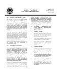
1.1
Introduction
This document, the Environmental Investigations Standard Operating Procedures and Quality
Assurance Manual, contains the standard operating and field quality assurance procedures used by Region
4 field investigators. The manual originated in 1980 with the title Engineering Support Branch Standard
Operating Procedures and Quality Assurance Manual , was revised in 1986 with the same title. It was revised
again in 1991 with the title, Environmental Compliance Branch Standard Operating Procedures and Quality
Assurance Manual. In 1996, it was revised with the present title. The specific procedures outlined in the
manual are based on the experiences of Region 4 field investigators or documents referenced at the end of
each section.
This manual will be provided to each Region 4 employee responsible for conducting field
investigations for activities contained in these Standard Operating Procedures (SOP). Each employee is
expected to read and be familiar with each section of the SOP. This is intended to be a dynamic document
and will be revised periodically as needed. Mention of trade names or commercial products does not
constitute endorsement or recommendation for use.
1.2
Performance Objectives
Performance objectives have been included at the beginning of sections and sub-sections where
applicable. The performance objective lists the minimum requirements necessary for meeting the intent of
the procedures that follow in the section. The purpose of the performance objective is to allow flexibility
within field procedures where appropriate; however any deviations from the procedures in the SOP should
be approved by the appropriate authority and thoroughly documented.
1.3
Section Objectives
Section objectives are included at the beginning of sections where performance objectives are not
applicable. Section objectives provide a brief summary of the intention and content of the section.
EISOPQAM
1-1
November 2001
SECTION 2
INVESTIGATIONS, INSPECTIONS, AND OVERVIEW ACTIVITIES
SECTION OBJECTIVES:
2.1
Define the standard types of investigations, inspections, and field studies conducted.
Outline the general requirements for study plans and reports for standard types of
investigations, inspections and field studies.
List available agency guidance and special requirements for the standard types of
investigations, inspections, and field studies.
Introduction
The investigations, inspections, and overview activities conducted can be broadly categorized as
either enforcement or non-enforcement related.
Enforcement related activities include criminal investigations, Resource Conservation and Recovery
Act (RCRA) case development inspections, RCRA comprehensive ground water monitoring evaluations,
water enforcement case preparation studies, National Pollutant Discharge Elimination System (NPDES)
compliance monitoring, diagnostic evaluations of municipal wastewater treatment plants, investigations of
Superfund hazardous waste sites, contractor overviews, investigations and monitoring of oil spills and
Superfund spills, and investigations of toxic episodes and spills.
Non-enforcement activities include investigations of potential Superfund hazardous waste sites for
National Priority Listing (NPL) purposes, technical assistance studies at municipal wastewater treatment
plants, studies involving water quality and permitting issues, studies and inspections of abandoned hazardous
waste sites, air quality studies, and a broad range of studies for national programs, as well as technical
assistance studies for state and local agencies. However, studies and data derived from non-enforcement type
investigations could be used for enforcement purposes. Field investigations include all environmental media
(i.e., surface and ground water, air, soils, sediments) and wastes.
EISOPQAM
2-1
November 2001
2.2
Potable Water Supply Investigations
Potable water supply investigations are usually conducted as part of a larger investigation such as
a spill, leaking tanks, nearby superfund site, etc. However, an investigation may be conducted independently
of a potential contamination source.
Potable water supply investigations may include collecting samples from wells, surface waters,
distribution systems, private residential wells, etc.
Special procedures apply when a sample is collected from a private or public potable water supply.
Investigators should always obtain the following information from the residents and/or owners in the event
contaminants are detected in the sample:
resident's and/or owner's name;
resident's and/or owner's mailing address; and
resident's and/or owner's home and work telephone numbers.
Immediately upon receipt of analytical data, the project leader should carefully examine the data.
Web sites listed at the bottom of this section may be useful in an evaluation. If any of the primary or
secondary drinking water standards are exceeded, or any priority pollutants, RCRA 40 CFR 261 Appendix
VIII compounds, or the CERCLA 40 CFR 302 list of hazardous substances are detected, the project leader
will immediately provide the information listed below to the appropriate individuals in the Water
Management Division or Waste Management Division. The Water Management Division primary contact
is Lee Thomas in the Water Programs Enforcement Branch; the secondary contact is Carol Tarras. The
Waste Management Division primary contact is Glenn Adams in the Office of Technical Services; the
secondary contact is Kevin Koporec.
the analytical data;
the name, address (including zip code) and telephone numbers of the residents and/or owners;
the site name and location; and
the EPA site identification number (if applicable).
Investigators should not release potable water supply data to anyone before providing it to the Water
Management Division.
Web sites that may be useful:
For the current MCLs and SMCLS with potential health effects and sources:
http://www.epa.gov/OGWDW/wot/appa.html
For a summary of drinking water health advisories:
http://www.epa.gov/ost/drinking/standards/
Region 4 Office of Technical Services http://www.epa.gov/region4/wastepgs/oftecser/oftecser.htm
Region 3 Risk Assessment tables
http://www.epa.gov/reg3hwmd/risk/riskmenu.htm
Region 9 Risk Assessment tables
http://www.epa.gov/region09/waste/sfund/prg/index.html
NCEA (ORD-Cinn.) web page
http://www.epa.gov/ncea/biblio.htm
Oak Ridge National Laboratory risk
http://risk.lsd.ornl.gov/homepage/rap_tool.htm
assessment page
EPA's Intergrated Risk Information
http://www.epa.gov/ngispgm3/iris/
System (ref. doses and slope factors):
EISOPQAM
2-2
November 2001
2.3
Civil Enforcement Investigations and Studies
2.3.1
Introduction
This SOP covers the field and operational aspects of conducting field investigations; however, it is
beyond the scope of this manual to cover all aspects of enforcement activities. Each enforcement
investigation must be tailored to meet the needs of the anticipated enforcement action. The lead attorney and
compliance specialists should be consulted on a continuing basis during the planning, conducting, and report
writing phases of enforcement investigations.
Civil investigations are conducted for the Water and Waste Management Divisions and the Air,
Pesticides, and Toxics Management Division to determine if a facility, site, or project is meeting the terms
of a Consent Decree, order, water permit, etc. These investigations are conducted under a number of
environmental laws which include:
2.3.2
The Clean Water Act (CWA, PL 92-500)
The Resource Conservation and Recovery Act (RCRA, PL 94-580)
The Hazardous and Solid Waste Amendments (HSWA) of 1984
The Comprehensive Environmental Response, Compensation, and Liability Act (Superfund)
The Superfund Amendments and Re-authorization Act (SARA) of 1986
The Clean Air Act (CAA 42 U. S.C. 1857 - 1857L, as amended)
The Toxic Substances Control Act (TSCA, PL 94-469)
Facility Entry
Authority -- Various federal environmental statutes grant EPA enforcement personnel authority to enter and
inspect facilities. The authority granted in each statute is similar to that stated below in Section 308 of the
Clean Water Act:
"(a)(B) the Administrator or his authorized representative, upon presentation of his
credentials (i) shall have a right of entry to, upon, or through any premises in which an
effluent source is located or in which any records required to be maintained. . .are located,
and
(ii) may at reasonable times have access to and copy any records, inspect any monitoring
equipment or method required. . . , and sample any effluents which the owner or operator
of such source is required to sample. . ."
For the specific requirements for conducting inspections and collecting data pursuant to a particular
Act, see: Section 308 of the Clean Water Act; Section 9 of the Federal Insecticide, Fungicide, and
Rodenticide Act; Section 3007 of the Resource Conservation and Recovery Act; Section 8 of the Toxic
Substances Control Act; Section 1445 of the Safe Drinking Water Act; Section 104 of the Comprehensive
Environmental Response, Compensation, and Liability Act (Superfund); and Titles I, III, and IV of the Clean
Air Act.
EISOPQAM
2-3
November 2001
2.3.3
Unreasonable Search and Seizure
EPA authority under the various Acts is subject to the "unreasonable search and seizure" provisions
of the Fourth Amendment to the Constitution. The prohibition is not against all searches and seizures, but
only those which are unreasonable or which valid consent, if required, has not been given. Consent, in this
context, means the intentional foregoing of right to privacy which is not the result of either fear, ignorance,
or trickery.
To comply with the Acts and avoid any "unreasonable search" or procedural problems, a facility
should be entered in the following manner:
1.
The facility premises should be entered through the main gate or through the entrance
designated by the source if in response to an inspection notification letter (a 308 letter for
example).
2.
The employee shall introduce herself/himself in a dignified, courteous manner to a
responsible plant official. A responsible plant official may be the owner, operator, officer,
or agent in charge of the facility, including the plant environmental engineer. Identification
credentials shall always be presented.
3.
If only a guard is present at the entrance, employees shall present their credentials and
suggest that the guard call their superior on the telephone. If the field investigators know
the name of the responsible official they are to see, they should request the guard call this
individual directly.
4.
If the company provides a general sign-in sheet, it is acceptable to sign it. Field
investigators shall not sign a release of liability (waiver) when entering a facility under the
authority of Federal law.
5.
If entry is refused, field investigators shall not contest the issue with the facility
representative, but will immediately do the following:
Obtain the name and position of the individual denying entry to the facility, and
record the date and time.
Cite the appropriate EPA authority to conduct the inspection, ask if the individual
denying entry heard and understood the reason for your presence and record the
answer and any reasons given for denial of entry.
Leave the premises immediately.
After leaving the facility, the field investigators shall, at the earliest possible time, inform their
immediate supervisor and the Office of Regional Counsel, by telephone of the events which took place and
seek guidance on how to proceed.
EISOPQAM
2-4
November 2001
2.3.4
Requesting Information
The various laws and statutes under which EPA operates address the protection of trade secrets and
confidential information. As a general policy, field investigators should not accept confidential information
unless it is necessary for carrying out Agency functions under a particular Act. As a matter of practice,
requests for confidential information can only be signed by an Agency employee who has had the appropriate
Confidential Business Information (CBI) training and certification.
In compliance with EPA regulations, an EPA request for company information, pursuant to statutory
authority, will contain a statement allowing the facility to designate all or part of the information requested
by the Agency as confidential by marking it according to: Code of Federal Regulations, Title 40, Part 2,
Section 203.41; or Federal Register, 41 FR 36902. In addition to citing the appropriate regulations, the
request for confidential information will state that:
1.
The company may, if it desires, assert a business confidentiality claim covering part or all
of the information in the manner described by [the applicable regulation], and that
information covered by such a claim will be disclosed by EPA only to the extent, and by
means of the procedures, set forth in [the applicable regulations]; and that
2.
If no such claim accompanies the information when it is received by EPA, it may be made
available to the public by EPA without further notice to the company.
If the collection of confidential information is required to carry out the responsibility of the Branch,
personnel should consult carefully with the appropriate operating Division staff and the Office of Regional
Counsel attorneys. In general, when such information is needed by Branch personnel, the request should state
that this information will be transmitted directly to the Office of Regional Counsel.
In general, Branch personnel shall not accept confidential information when conducting a plant
evaluation, inspection, or reconnaissance. When Branch personnel must collect or observe confidential
information, a separate logbook shall be maintained. When confidential information is entered into an
inspector's logbook, the entire logbook and each page containing confidential information shall be marked
"CONFIDENTIALITY CLAIM." Upon returning to the EPA Region 4, facility, all such information shall
be maintained in a locked filing cabinet and the Office of Regional Counsel shall be notified for ultimate
disposition of the material.
All field investigators conducting investigations or inspections should be familiar with the inspection
provisions of these acts, i.e., CWA (Section 308), RCRA (Section 3007), CERCLA (Section 104), and TSCA
(Section 11).
2.3.5
Photographs
At no time should field investigators be denied the opportunity to take photographs during an
investigation. If photographs are denied and no other means can be arranged to get the photographs, this is
considered a denial of access by the facility. At some facilities the process operations and/or equipment may
be claimed as being proprietary. In these cases, the facility may make a CBI request to the Office of Regional
Council (ORC). Generally, providing the facility with a duplicate copy of uncut prints for their review is
acceptable to both parties. If this is unacceptable to the facility, the investigator may allow the facility to take
the photographs, review them, and provide copies to EPA.
EISOPQAM
2-5
November 2001
2.3.6
Split Samples
The inspection provisions of RCRA (Section 3007) and CERCLA (Section 104) require that, "If the
officer or employee obtains any samples, prior to leaving the premises, he shall give to the owner, operator,
or agent in charge a receipt describing the samples obtained and if requested a portion of each such sample
equal in volume or weight to the portion retained." As a matter of policy, an offer will be made to the owner,
operator, or agent in charge to split all samples collected on facility property.
2.4
Criminal Investigations and Studies
At the request of the Criminal Investigations Division (CID) and with the concurrence of the
Regional Administrator/Deputy Regional Administrator, technical support for criminal investigations is
provided. Only experienced personnel with adequate training (such as on-site supervision by senior
investigators or the Criminal Investigations Course offered by the Federal Law Enforcement Training Center)
should be project leaders during such investigations. Technical support shall be provided at the request of
the CID Special Agent-in-Charge of the investigation in accordance with Appendix F of this SOP.
EISOPQAM
2-6
November 2001
2.5
Clean Water Act Compliance Monitoring Inspections
2.5.1
Introduction
The term "compliance monitoring" covers all activities undertaken to ascertain a permitee's or
discharger's compliance status. This includes, but is not limited to, Clean Water Act (CWA) compliance
monitoring inspections and compliance review, e.g., the review of Discharge Monitoring Reports (DMR) or
compliance schedule reports. The main functions of CWA compliance monitoring inspections are to verify
the integrity of the self-monitoring information and to develop the basis for possible follow-up compliance
or enforcement actions. All compliance monitoring inspections shall be conducted as though an enforcement
action would result. General guidance for conducting compliance monitoring inspections is found in the US
EPA, NPDES Compliance Inspection Manual (1). Compliance monitoring inspections are usually requested
by the Clean Water Act Enforcement Section, Water Programs Enforcement Branch, Water Management
Division.
A number of different types of compliance monitoring inspections have been defined including:
compliance evaluation inspections (CEI), compliance sampling inspections (CSI), toxic compliance sampling
inspections (XSI), compliance biomonitoring inspections (CBI), performance audit inspections (PAI),
diagnostic evaluations (DE), reconnaissance inspections (RI), pretreatment compliance inspections (PCI),
sludge inspections (SI), legal support inspections (LSI), and Municipal Wastewater Treatment Plant technical
assistance (TA) studies.
Activities associated with a visit to any facility for a compliance inspection shall not be double
counted. Thus, a single visit cannot be counted as both a CSI and a CEI; it must be reported as one or the
other. However, a single visit that encompasses separate activities (e.g., a PAI or legal support investigation)
will be reported and counted as two separate activities. A compliance monitoring inspection (all types) is
not considered complete until the appropriate portions of the Compliance Inspection Report Form (EPA Form
3560-3) have been completed and the information from the coding section entered into the permit compliance
system (PCS).
Inspection Notification
Generally, CSIs and CEIs are conducted unannounced unless there is a reason to conduct the
inspection on an announced basis. Routine PAI's and DE's are typically announced inspections due to the
complexity of the logistics involved in these types of investigations.
2.5.2
CWA Inspection Types
Compliance Evaluation Inspection (CEI)
The CEI is a nonsampling inspection designed to verify permittee compliance with
applicable permit self-monitoring requirements, effluent limits, and compliance schedules. This inspection
involves records reviews, visual observations, and evaluations of the treatment facilities, laboratories,
effluents, receiving water, etc. The CEI examines both chemical and biological self-monitoring and forms
the basis for all other inspection types except the Reconnaissance Inspection. Guidance for conducting CEIs
is given in the NPDES Compliance Evaluation Inspection Manual (2).
EISOPQAM
2-7
November 2001
Compliance Sampling Inspections (CSI)
CSI's are conducted where representative sample(s) of a permittee's influent and/or effluent are
collected and analyzed 1) to verify the accuracy of the permittee's discharge monitoring reports, 2) to
determine the quantity and quality of the effluent, 3) to develop permits, and/or 4) where appropriate, as
evidence for enforcement proceedings. This activity also includes the same objectives listed for CEI's, and
where appropriate, may serve to gather detailed information for the possible institution of legal action against
the permittee. Guidance for conducting CSI's is given in the NPDES Compliance Sampling Inspection
Manual (3).
Toxic Sampling Inspections (XSI)
The XSI has the same objectives as a conventional CSI. However, it places increased emphasis on
toxic substances regulated by the NPDES permit. The XSI covers priority pollutants other than heavy metals,
phenols, and cyanide, which are typically included in a CSI (if regulated by the NPDES permit). An XSI
uses more resources than a CSI because highly sophisticated techniques are required to sample and analyze
toxic pollutants. An XSI may also evaluate raw materials, process operations, and treatment facilities to
identify toxic substances requiring controls.
Compliance Biomonitoring Inspection (CBI)
A CBI is an inspection utilizing a static or flow-through bioassay, in lieu of, or in addition to, the
collection of samples. The objectives of this inspection are to:
Identify those permittees which may be meeting the minimum technology based
requirements of the CWA, but whose level of treatment is not sufficient to ensure the
biological integrity of the receiving waters;
Identify those permittees which may have potential toxic substances in their discharge(s)
that have not been identified or included in their NPDES permit; and
Evaluate compliance with acute or chronic toxicity permit limit requirements.
In those instances where biomonitoring reveals the presence of toxic substances not addressed in the
issued permit, the permittee may be required through the 308 process to chemically and/or physically
characterize the composition of the discharge to identify and quantify the toxic substance or substances
(CWA Section 308). Guidance for conducting these inspections is given in the Compliance Bio-Monitoring
Inspection Manual (4).
Performance Audit Inspection (PAI)
The PAI is used to evaluate the permittee's self-monitoring program. As with a CEI, the PAI is used
to verify the permittee's reported data and compliance through a records check. However, the PAI provides
a more resource-intensive review of the permittee's self-monitoring program and evaluates the permittee's
procedures for sample collection, flow measurement, chain-of-custody, laboratory analyses, data compilation,
reporting, and other areas related to the self-monitoring program. During a CEI, the inspector makes a
cursory visual observation of the treatment facility, laboratory, effluents, and receiving waters. During a PAI,
the inspector actually observes the permittee performing the self-monitoring process from sample collection
and flow measurement through laboratory analyses, data workup, and reporting. The PAI does not include
the collection of samples by the inspector. However, the inspector may require the permittee to analyze
performance samples for laboratory evaluation purposes.
EISOPQAM
2-8
November 2001
Diagnostic Evaluations (DE)
The DE is a detailed performance evaluation that focuses primarily on municipal Publicly Owned
Treatment Works (POTWs) which are not in compliance with permit requirements. The DE is designed to
evaluate the POTW's design, operations, and influent/effluent wastewater characteristics and to provide a
comprehensive evaluation of the reasons why the facility is not meeting permit limits. The final product
consists of a formal report with data, data interpretation, and recommendations suitable for use in technical
assistance, negotiations, and enforcement actions.
Reconnaissance Inspection (RI)
The RI is used to obtain a preliminary overview of a permittee's compliance program. The inspector
performs a brief visual inspection of the permittee's treatment facility, effluent, and receiving waters. The
RI is intended to obtain a broad coverage of permittees of unknown status with a minimum amount of
resources.
Pretreatment Compliance Inspection (PCI)
The PCI evaluates the POTWs implementation of its approved pretreatment program. It includes
a review of the POTWs records on monitoring, inspections, and enforcement activities for its industrial users.
The PCI is usually conducted concurrently with another NPDES inspection of the POTW.
Sludge Inspection (SI)
The SI is primarily conducted at POTWs. Waste sludge generation and disposal practices are
evaluated under the 40 CFR 503 regulations. The SI includes a review of the sludge monitoring records,
sludge handling facilities, and sludge disposal practices.
Legal Support Inspection (LSI)
The LSI is an inspection conducted to satisfy a specific enforcement related problem. An example
of this type of inspection may be an enforcement request to inspect a permittee to see if it is appropriate to
terminate a specific enforcement order or a request to gather data to support a planned action.
2.5.3
Study Plans
Routine NPDES inspections (e.g., PAIs, CSIs, etc.) do not require a written study plan. Detailed
investigations, such as diagnostic evaluations, water quality studies, and other large scale technical
evaluations require a written study plan which should include the following minimal information:
Introduction -- The name and location of the project, study dates, requestor, reason for
request (e.g., NPDES compliance problems), project leader, and a list of EPA and other
appropriate study contacts and telephone numbers.
Study Objectives -- A detailed description of the primary objectives of the project.
Sampling Schedule -- A detailed table showing all projected sampling stations, sampling
parameters, and the total number of samples to be analyzed.
The study plan may include more detailed information depending on the nature and complexity of
the project. Copies of the study plan should be provided to Clean Water Act Section staff.
EISOPQAM
2-9
November 2001
2.5.4
NPDES Compliance Inspection Reports
The results of all compliance inspections shall be reported utilizing the NPDES Compliance
Inspection Report Form (EPA Form 3560-3). The completed form, formal narrative report, and transmittal
memorandum constitute a compliance inspection report for all routine compliance inspections conducted by
Branch personnel.
The completed inspection reports are forwarded to appropriate parties for action and follow-up. The
state and regional program office are kept fully informed via copies of all correspondence. In cases where
EPA is involved in litigation with a permittee, no reports will be sent to the permittee without permission
from legal counsel.
Completion of NPDES Compliance Inspection Report Form (EPA Form 3560-3)
General instructions for completing EPA Form 3560-3 are printed on the back of the form.
The forms shall be signed by the investigator and dated on the day that the form is completed (not
the inspection date). The name of the state inspector should be included for joint inspections. All routine
compliance inspections forms shall be reviewed by the supervisor, who will sign and date the 3560-3 form
in the "Reviewed By" section.
EISOPQAM
2 - 10
November 2001
2.6
Superfund Investigations, Technical Assistance, and Overview Activities
2.6.1
Introduction
Superfund field activities include remedial investigations and feasibility studies (RI/FS), field
investigations of potentially or known contaminated areas (FI), technical assistance (TA), and on-site
overviews (OV) of Superfund contractor, potentially responsible party (PRP) contractor, and state personnel.
2.6.2
Superfund Investigation Types
Remedial Investigations/Feasibility Studies (RI/FS)
Remedial investigations are conducted to determine the nature and extent of contamination at
specific Superfund sites. Investigations may include installation of temporary or permanent monitoring
wells, geophysical exploration, surface and subsurface soil sampling, off-site environmental sampling, etc.
Feasibility studies may be conducted concurrently with an RI to develop and evaluate potential remedial
action alternatives. The Guidance for Conducting Remedial Investigations and Feasibility Studies under
CERCLA (5) is useful for planning RI/FS investigations.
Field Investigations (FI)
These include all field investigations, other than RIs, of potentially or known contaminated areas,
and they support all phases of the Superfund program. These investigations may include sampling of ground
water, surface and subsurface soils, rivers, lakes, etc., and/or may entail geophysical studies, global
positioning system (GPS) activities, etc.
Overviews (OV)
Activities include on-site overview of the field work of EPA Superfund field contractors, PRP
contractors, and State Superfund contractors. Overviews are conducted to evaluate the contractors'
capabilities and to correct deficiencies in performing Superfund field investigations. The Region 4,
Hazardous Waste Field Overview Checklist (Exhibit 2.1) is completed during the overview, and a written
report presenting the overview findings is completed and transmitted to the appropriate official in the Waste
Management Division.
Technical Assistance (TA)
Activities range from directing field investigations with non-Agency field support to responding to
telephone questions concerning all aspects of Superfund field investigations. In addition, field personnel
provide a variety of training and technical assistance activities for Regional, State, and other Federal agency
personnel in methods of conducting field operations at hazardous waste sites.
2.6.3
Planning for Field Investigative Support
Periodic meetings are typically held between a representative(s) of the Superfund Staff and the Waste
Management Division staff to discuss proposed initiatives and specific investigation needs. These meetings
are usually conducted in October for yearly planning, and more frequently for quarterly planning.
Based on the priorities agreed upon by the Superfund Staff, and the Waste Management Division,
field investigation schedules are prepared by the Superfund Staff and updated as needed.
EISOPQAM
2 - 11
November 2001
2.6.4
Requests for Superfund Studies
Superfund investigations are prioritized by the Waste Management Division based on the need for
field investigative support. Specific investigations are usually requested by project managers of the various
Superfund programs, however, they may be requested by state agencies, congressional officials, etc. Routine
requests for field investigative support are coordinated with the Superfund Staff leader. Requests are then
brought to the Superfund Staff for scheduling and project leader/staff assignment. Although the initial
contact may be by telephone or electronic mail, a formal request memorandum with a request form is
required prior to commencement of the investigation.
2.6.5
Investigation Study Plans
Study plans are prepared for all Superfund investigations except overviews and some emergency
investigations. Study plans for typical Superfund field investigations must be issued at least one week prior
to the investigation. The timing and nature of some emergency requests may preclude the issuance of a study
plan.
A copy of the study plan in draft form will be provided to the requestor to insure that the plan will
meet their objectives. As a general rule, the Data Quality Objective (DQO) process should be consulted
during the study plan preparation phase. The study plan should include, as appropriate:
Introduction -- The project leader and support staff, requestor from the appropriate
Superfund Branch, and the objective(s) of the investigation.
Background -- Facility compliance history, manufacturing processes, types of wastes
produced, waste treatment methods, etc.
Scope -- The study design should be discussed in this section including the number and
location of the samples to be collected, information which will be obtained, and records to
be reviewed.
Logistics -- The travel and study dates.
Methodology -- Analyses to be conducted and who will conduct analyses, field and
laboratory SOP references, and when samples will be received by the laboratory.
If the study is an RI, the following additional information, where appropriate, should be included:
EISOPQAM
Site background and physical setting
Initial Evaluation
Sampling DQO
Site Management Plan
Quality Assurance Project Plan
Field Sampling and Analyses Plan
Field Health & Safety Plan.
2 - 12
November 2001
2.6.6
Investigation Reports
Reports will be completed after each investigation and will contain the following, as appropriate:
Introduction -- When the investigation was conducted; EPA, state, or other regulatory
agency participation; facility representatives and what their participation included; who
requested the investigation; and the objectives.
Background -- Study area descriptions, manufacturing process and waste handling priorities,
results of previous investigations, etc. A site map depicting major structures and facilities,
as well as sampling locations will be included.
Summary -- A brief summary of the key results and conclusions of the study.
Discussion -- All aspects pertinent to the investigation, such as analytical results;
deficiencies; site hydrology; an evaluation of the monitoring well system; a site map
showing monitoring well locations, topography, and ground water flow direction; well
depths; and ground water elevations.
Methodology -- A statement indicating that this SOP was followed and/or reasons why not
and whether or not samples were split and with whom.
Conclusions -- At the discretion of the author, a conclusions section for complex
investigations.
Reference and Appendices -- Laboratory data sheets, checklists, etc.
If the study is an RI, the following additional information should also be included where appropriate:
Site information, including site description, site history, previous investigation results,
regulatory actions, demography, and surrounding land use.
Sampling strategy.
Nature and extent of contamination.
Contaminant fate and transport.
In emergencies, samples are usually collected quickly and analyzed on a fast turn-around basis. In
these cases, Team personnel may provide printed copies of sample data to the requestor as soon as practical.
Where appropriate, a letter report detailing the field activities associated with the emergency field
investigation will be prepared and transmitted to the requestor.
Internal Peer Review and Report Recipients
All Superfund reports will be reviewed internally. Final copies of the report will be sent to the
requestor. If facility or state personnel request a copy of the report, this will be indicated in the report
transmittal memo. The Regional Superfund program is responsible for distribution of data and reports to site
owners or operators and to the public. All requests for such information should be referred to the proper
program official for action.
EISOPQAM
2 - 13
November 2001
2.7
RCRA Inspections, Investigations, and Overview Activities
2.7.1
Introduction
RCRA field activities include comprehensive ground water monitoring evaluations (CME), RCRA
facility assessments (RFAs), case development inspection/evaluations (CDIE) for the RCRA programs and
field investigations for the Criminal Investigations Division (CID), and on-site field overviews (OV) of state,
RCRA contractor, and federal facility personnel.
2.7.2
RCRA Investigation Types
Comprehensive Ground Water Monitoring Evaluation (CME)
The CME is an overall review of a facility's compliance with all applicable RCRA requirements to
determine adequacy of the ground water monitoring system. It includes an on-site examination of records
and other documents and an evaluation of the facility's compliance with applicable RCRA requirements.
Also evaluated is the effectiveness of the ground water monitoring system and the facility's hydrogeological
conditions. Sampling and analysis of the ground water are usually conducted. Guidance for conducting
CMEs is included in the RCRA Ground-Water Monitoring Technical Guidance Document (6).
RCRA Facility Assessment (RFA)
The RFA is an agency lead activity which is the first step in a corrective action program. The
purpose of the RFA is to identify known and/or probable releases of hazardous wastes or other constituents
at solid waste management units (SWMUs) and at previously unaddressed regulated units. It includes a
"desk-top" review of information submitted by the owner/operator to EPA and State Agencies. The RFA
also consists of an on-site visit, and potentially a subsequent sampling investigation (confirmatory sampling)
to determine whether or not releases of hazardous wastes or constituents have occurred. Guidance for
conducting the RFA is in the RCRA Facility Assessment Guidance,(7).
Case Development Investigation/Evaluation (CDIE)
These include all RCRA field investigations other than CME's and RFA's, including field sampling
investigations, closure/post closure investigations, environmental investigations, trial burns, delisting
investigations, etc. The type of investigation dictates the specific field methodology. The CDIE is conducted
to gather information on the composition/characteristics of wastes and/or an area impacted by the operation
of a RCRA facility. The CDIE may also include verification of a sampling and analysis plan, collection of
information on facility design and operation, verification of manifest descriptions, or other unanticipated
needs or requests necessary for case development.
Overviews (OV)
Overviews of state RCRA compliance inspections or RCRA contractor inspections are conducted
to evaluate their capability to conduct RCRA field investigations. The Region 4, Hazardous Waste Field
Overview Checklist (Exhibit 2.1) is completed during the overview, and a written report presenting the
overview findings is completed and transmitted to the appropriate EPA regional RCRA official.
EISOPQAM
2 - 14
November 2001
2.7.3
Planning for Field Investigative Support
Periodic meetings are typically held between representative(s) of SESD and the RCRA Branch staff
to discuss proposed initiatives and specific investigation needs. These meetings are usually conducted in
October for yearly planning, and more frequently for quarterly planning. Based on the priorities agreed upon,
a tentative field investigation schedule is prepared and updated as needed.
2.7.4
Requests for RCRA Studies
RCRA investigations are prioritized by the Region 4, RCRA programs based on their need for field
investigative support. Requests for field investigative support are coordinated with the RCRA team
Supervisor or their designee(s). A memorandum with a request form is recommended prior to
commencement of the investigation.
2.7.5
Investigation Study Plans
Study plans are prepared for all RCRA investigations and issued at least one week prior to the
investigation. A copy of the draft study plan should be provided to the RCRA program requestor to insure
that the investigation will meet the enforcement or permitting objectives. As a general rule, the Data Quality
Objective (DQO) process should be consulted during the study plan preparation phase. The study plan
should include, as appropriate:
2.7.6
Introduction -- The project leader and support staff, requestor from the RCRA program, and the
objective(s) of the investigation.
Background -- Facility compliance history, manufacturing processes, types of wastes produced,
waste treatment methods, etc.
Scope -- A discussion of the study design including the number and locations of the samples to
be collected. Information which will be obtained and records to be reviewed.
Logistics -- The travel, study dates and personnel.
Methodology -- Analyses to be conducted and who will conduct analyses, field and laboratory
SOP references, and when samples will be received by the laboratory.
Investigation Reports
Reports will be completed after each investigation and will contain the following, as appropriate:
Introduction -- When the investigation was conducted; EPA, state, or other regulatory agency
participation; facility representatives and what their participation included; who requested the
investigation; and the objectives.
Background -- Study area descriptions, manufacturing process and waste handling priorities,
results of previous investigations, etc.
Summary -- A brief summary of the key results and conclusions of the study.
Discussion -- All aspects pertinent to the investigation e.g., sampling, figures, photographs,
analytical results, RCRA deficiencies, etc.
EISOPQAM
2 - 15
November 2001
Methodology -- What information was obtained and from whom, what sampling procedures
were used, what analytical methods were used, etc. A statement indicating that this SOP was
followed and/or reasons for deviations and whether or not samples were split and with whom.
Conclusions -- At the discretion of the investigator, a conclusions section for complex
investigations.
Reference and Appendices -- Raw data, checklists, etc.
If the study was a CME, the following information should be included where appropriate:
A discussion of site hydrology.
An evaluation of the monitoring well system.
An evaluation of the assessment plan.
A site map showing monitoring well locations, SWMU's, topography, ground water flow
direction, etc.
Well depth, ground water elevations.
CME checklist.
Internal Peer Review and Report Recipients
All RCRA plans and reports will be reviewed internally. Final copies of the plan/report will be sent
to the requestor. If facility or state personnel request a copy of the report, this will be indicated in the report
transmittal memorandum.
2.8
Underground Storage Tank (UST) Investigations
2.8.1
Introduction
USTs were traditionally investigated because of potential, or actual, contamination of the
environment from petroleum products. More recently, UST investigations have been conducted because
tanks contain hazardous substances. UST field investigations are requested by the Water Management
Division, Ground Water/Drinking Water Branch, UST Section and usually involve ground water and/or soil
sampling for UST constituents or related products.
UST investigation objectives may include:
•
Determining if there has been a release to the environment from the UST.
Determining if potable wells are contaminated with UST constituents.
•
Determining if ground water is contaminated with UST constituents.
•
Determining if vicinity soils have been contaminated with UST constituents.
Determining the direction of the contamination plume and the source of the contamination.
EISOPQAM
2 - 16
November 2001
2.8.2
Investigation Study Plans
Study plans are prepared for all UST investigations and must be issued at least one week prior to the
investigation. The timing and nature of some emergency requests may preclude the issuance of a study plan.
A copy of the study plan in draft form will be provided to the requestor to ensure that the plan will
meet their objectives. As a general rule, the Data Quality Objectives (DQO) process will be consulted during
the study plan preparation phase. The study plan should include, as appropriate:
2.8.3
•
Introduction – The project leader and support staff, requestor from the UST Section, and the
objective(s) of the investigation.
•
Background – Facility compliance history, manufacturing processes, types of wastes produced,
waste treatment methods, etc.
•
Scope – The study design should be discussed in this section including the number and location
of the samples to be collected, information which will be obtained, and records to be reviewed.
•
Logistics – The travel and study dates.
•
Methodology – Analyses to be conducted and who will conduct analyses, field and laboratory
SOP references, and when samples will be received by the laboratory.
Investigation Reports
An investigation report containing the following information will be completed:
Introduction -- When , where and why the investigation was conducted and requesting office.
Staff who conducted the investigation.
Background -- Site history, description, and results of previous studies.
Summary -- Summary of the field investigation and resulting analyses, which constituents are
present, direction of plume movement if determined, possible sources of contamination, and
potable well owners’ names, phone numbers, addresses, if appropriate.
Sketches/maps -- Showing sampling locations, UST locations, direction of plume, etc.
•
Methodology – Reference to field and laboratory SOPs
Internal Peer Review and Report Recipients
UST reports will be reviewed internally. Final copies of the report will be sent to the requestor in
the UST Section. If private or public potable water supplies are sampled, refer to Section 2.2 for reporting
requirements.
EISOPQAM
2 - 17
November 2001
2.9
Underground Injection Control (UIC) Investigations
2.9.1
Introduction
Laws protecting ground water from contamination by injection of wastes allow for the sampling of
injection wells as well as nearby wells. UIC field investigations are requested primarily by the Region 4,
Water Management Division, Ground Water/Drinking Water Branch, GW & UIC Section and usually
involves ground water sampling for constituents related to the wastes being injected.
UIC investigation objectives may include:
2.9.2
Determining if vicinity potable water wells are contaminated with waste products from the
injection wells.
Determining if vicinity ground water monitoring wells are contaminated with waste products
from the injection wells.
Determining the direction of the contamination plume and the source of the contamination.
Investigation Study Plans
Study plans are prepared for all UIC investigations and must be issued at least one week prior to the
investigation. The timing and nature of some emergency requests may preclude the issuance of a study plan.
A copy of the study plan in draft form will be provided to the requestor to ensure that the plan will
meet their objectives. As a general rule, the Data Quality Objectives (DQO) process will be consulted during
the study plan preparation phase. The study plan should include, as appropriate:
2.9.3
•
Introduction – The project leader and support staff, requestor from the GW & UIC Section, and
the objective(s) of the investigation.
•
Background – Facility compliance history, manufacturing processes, types of wastes produced,
waste treatment methods, etc.
•
Scope – The study design should be discussed in this section including the number and location
of the samples to be collected, information which will be obtained, and records to be reviewed.
•
Logistics – The travel and study dates.
•
Methodology – Analyses to be conducted and who will conduct analyses, field and laboratory
SOP references, and when samples will be received by the laboratory.
Investigation Reports
An investigation report containing the following information will be completed:
Introduction -- When , where and why the investigation was conducted and requesting office.
Staff who conducted the investigation.
Background -- Site history, description, and results of previous studies.
EISOPQAM
2 - 18
November 2001
Summary -- Summary of the field investigation and resulting analyses, which constituents are
present, direction of plume movement if determined, possible sources of contamination, and
potable well owners’ names, phone numbers, addresses, if appropriate.
Sketches/maps -- Showing sampling locations, location of injection well(s), other pertinent
information
•
Methodology – Reference to field and laboratory SOPs
Internal Peer Review and Report Recipients
UIC reports will be reviewed internally. Final copies of the report will be sent to the requestor in
the GW & UIC Section. If private or public potable water supplies are sampled, refer to Section 2.2 for
reporting requirements.
2.10
Ambient Air Monitoring Evaluations And Audits
2.10.1 Introduction
In 1979, the US EPA established a plan for obtaining reliable ambient air quality data. The plan
includes a network of State and Local Air Monitoring Stations (SLAMS). The regulations governing the
network (40 CFR 58) cover the data collection and reporting requirements for state and local air pollution
control agencies. The purpose of this section is to provide procedures for the inspection and evaluation of
the SLAMS network. Each SLAMS site must meet criteria for network design, instrument exposure, sample
inlet, etc.
2.10.2 NAMS/SLAMS Site Evaluations
State and Local Air Monitoring Stations (SLAMS)
A SLAMS network should be designed to meet a minimum of four basic monitoring objectives.
Each SLAM site within a network must meet at least one of the following objectives:
To determine the highest concentrations expected to occur in the area covered by the network.
To determine representative concentrations in areas of high population density.
To determine the impact of ambient pollution levels of significant sources or source categories.
To determine the general background concentration levels.
National Air Monitoring Stations (NAMS)
NAMS are a selected subset of the SLAMS sites, covering urban and multi-source areas. The
emphasis is on areas of maximum concentrations and high population density. NAMS, like SLAMS, must
conform to EPA siting criteria and operate according to quality assurance procedures that meet or exceed
EPA's minimum specifications. The NAMS differ from the SLAMS in that NAMS must use continuous
automated instruments for gaseous pollutants.
EISOPQAM
2 - 19
November 2001
The NAMS fall into two categories:
Category (a) - stations in areas of expected maximum concentrations (usually middle scale).
Category (b) - stations in areas with both poor air quality and high population density. These
areas are not necessarily those with expected maximum concentrations. They will usually be
densely populated neighborhoods, but may be areas where sensitive individuals are likely to live
or work, if such areas are common to the neighborhood.
Urban areas where NAMS are required will usually have both types of stations. It is possible that
only one monitoring station will be needed for PM10 or SO2, in which case it must be a Category (a) station.
EISOPQAM
2 - 20
November 2001
Network Design
Network design for State and Local Air Monitoring Stations (SLAMS), National Air Monitoring
Stations (NAMS), and Photochemical Assessment Monitoring Stations (PAMS) is detailed in Appendix D
of 40 CFR 58. Tables 2.10.1 and 2.10.2 show the population levels for which NAMS monitoring is required.
The required spatial scales for NAMS are shown in Table 2.10.3. Although SLAMS do not have specific
scale requirements, the scales that are appropriate to each pollutant are also shown in Table 2.10.3. Selection
of urban areas and actual number of stations per area is jointly determined by EPA and the state agency.
TABLE 2.10.1
GUIDELINES for PM10 and SO2 NAMS NETWORK SIZE
(APPROXIMATE NUMBER of STATIONS PER AREA)
Population Area
Higha
>1,000,000
500,000-1,000,000
250,000-500,000
100,000-250,000
6-10
4-8
3-4
1-2
Population Concentration
Mediumb
4-8
2-4
1-2
0-1
Lowc
2-4
1-2
0-1
0
(a) PM10: High concentration areas are those for which ambient PM10 data show ambient
concentrations exceeding PM10 National Ambient Air Quality Standards (NAAQS) by
20% or more.
SO2: Defined as high when the ambient concentration exceeds the level of the
primary NAAQS.
(b) PM10: Ambient concentrations exceed 80% of the NAAQS.
SO2: Ambient concentrations exceed 60% of the primary or 100% of the secondary
NAAQS.
(c) PM10: Ambient concentrations are less than 80% of the NAAQS.
SO2: Ambient concentrations are less than 60% of the primary or 100% of the secondary
NAAQS.
EISOPQAM
2 - 21
November 2001
TABLE 2.10.2
POPULATION LEVELS FOR WHICH NAMS MONITORING OF POLLUTANTS OTHER THAN
PM10 AND SO2 IS REQUIRED
POLLUTANT
POPULATION
Lead
CO
Ozone
NO2
PM2.5
500,000a
500,000
200,000
1,000,000
N/A 35-50 sites total
(a) The minimum is also a SLAMS requirement. NAMS monitoring is also required
whenever the NAAQS has been exceeded in any of the last eight quarters.
TABLE 2.10.3
SUMMARY of SPATIAL SCALES USUALLY NEEDED for SLAMS and NAMS
Scale Appropriate for SLAMS
Spatial Scale
SO2
CO
O3
NO2
Pb
PM10
PM2.
5
Micro
X
X
X
X
Middle
X
X
X
X
X
X
X
X
X
X
X
X
X
X
X
X
X
X
X
Neighborhood
X
Urban
X
X
Regional
X
X
Scale Appropriate for NAMS
Spatial Scale
SO2
CO
O3
NO2
Pb
PM10
PM2.
5
Micro
X
Middle
Neighborhood
Urban
X
X
X
X
X
X
X
X
X1
X
X
X1
X
X
X
X2
X2
Regional
1
Only permitted if representative of many such micro-scale environments in a residential district (for middle
scale, at least two).
2
Either urban or regional scale for regional transport sites.
EISOPQAM
2 - 22
November 2001
Monitoring Methodology
The monitoring methods that must be used in NAMS/SLAMS are specified in 40 CFR 58, Appendix
C (hereafter referred to as Appendix C). Reference methods (or their equivalent) must be used for all
regulatory purposes.
An analyzer with a nonconforming range greater than twice the upper limit may be used if it has
more than one range. At least one of these ranges must be designated a reference or equivalent method and
it must be the one in which the pollutant concentration is likely to occur. Further, the EPA Administrator
must determine that the resolution of the range is adequate. See Section 2.6, Appendix C, for further details.
Requests for approval of a sampling method must be submitted to the United States Environmental
Protection Agency, National Exposure Research Laboratory (NERL), Human Exposure and Atmospheric
Sciences Division (MD-46), Research Triangle Park, North Carolina 27711.
Probe Siting
Probe siting criteria for State and Local Air Monitoring Stations (SLAMS), National Air Monitoring
Stations (NAMS), and Photochemical Assessment Monitoring Stations (PAMS) is detailed in Appendix E
of 40 CFR 58. Tables 2.10.4 and 2.10.5 display the requirements for probe siting. For further details,
clarification, or justification, refer to Appendix E of 40 CFR 58.
Borosilicate glass and FEP Teflon®, or their equivalent, are acceptable materials for SLAMS/NAMS
intake sampling lines. FEP Teflon® is not acceptable for VOC and carbonyl sampling at PAMS sites.
Borosilicate glass, stainless steel, or its equivalent, are the acceptable probe materials for VOC and carbonyl
sampling. The residence time in sampling probes for reactive gases must be less than 20 seconds.
EISOPQAM
2 - 23
November 2001
TABLE 2.10.4
SUMMARY of PROBE SITING CRITERIA
Horizontal and
Vertical
Distance From
Supporting
Structure 1
Distance From
Trees to Probe
Distance From
Roadways to
Probe
Pollutant
Scale
Height Above
Ground(m)
SO2 2,3,4,5
All
3 - 15
>1
>10
N/A
CO 3,4,6
Micro
3±½
>1
>10
2-10
All Others
3 - 15
>1
>10
See Table
2.10.5
O3 2,3,4
All
3 - 15
>1
>10
See Table
2.10.5
NO2 2,3,4
All
3 - 15
>1
>10
See Table
2.10.5
Micro
2-7
>10
(All Scales)
See Table
2.10.5
All Others
3 - 15
>2
(All Scales,
Horizontal
Distance)
Micro
2-7
>10
(All Scales)
5-15
All Others
3 - 15
>2
(All Scales,
Horizontal
Distance)
>2
(All Scales,
Horizontal
Distance)
>10
(All Scales)
Pb 2,3,4,5,7,8
PM10 2,3,4,5,7,8
PM2.5 2,3,4,5,7,8
See 58CFR,
App. E
2-10
See 58CFR,
App. E
1.
When probe is located on a rooftop, this separation distance is in reference to walls, parapets, or penthouses.
2.
Should be greater than 20 meters from tree driplines and must be 10 meters from the dripline when trees act as an
obstruction.
3.
Distance from inlet probe to obstacle, such as buildings, must be at least twice the height the obstacle protrudes above the
inlet pole. Sites not meeting this criterion would be classified as middle scale.
4.
Must have unrestricted airflow 270 degrees around the inlet probe, or 180 degrees if the probe is on the side of a building.
5.
No furnace or incinerator flues should be nearby. Distance is dependent on height of furnace or incineration flues, type
of fuel or waste burned, and quality of fuel (sulfur, ash, or lead content). This is to avoid undue influences from minor
pollutant sources.
6.
The horizontal and vertical distance from supporting structures must be greater than 1 meter. (When the probe is located
on a rooftop, this distance is in reference to walls, parapets, or penthouses located on the roof).
7.
Must be greater than 10 meters from a street intersection and should be located mid-block.
8.
For collocated Pb and PM10 samplers, a 2-4 meter separation distance must be met.
9.
Must have unrestricted airflow 270 degrees around the sampler, except for street canyon sites.
EISOPQAM
2 - 24
November 2001
TABLE 2.10.5
MINIMUM DISTANCE BETWEEN SAMPLING PROBE and ROADWAYS
(EDGE of NEAREST TRAFFIC LANE)
Roadway Average
Daily Traffic (ADT)
(vehicles per day)
Minimum Distance
Between Roadways and
Stations* (meters)
Neighborhood Scale CO Stations
<10,000
15,000
10
25
20,000
30,000
45
80
40,000
50,000
115
135
>60,000
>150
Neighborhood and Urban Scale Ozone and NO2 Stations
<10,000
15,000
20,000
40,000
70,000
>110,000
10
20
30
50
100
>250
Lead Stations
Micro Scale
Middle
Neighborhood,
Urban Scale
Regional
Scale
5 - 15
5 - 15
5 - 15
>15 - 50
>15 - 75
>15 - 100
>50
>75
>100
10,000
20,000
40,000
* Distances should be interpolated based on traffic flow.
2.10.3 State and Local QA Plan Reviews
Introduction
40 CFR, Part 58, Appendix A specifies the minimum quality assurance (QA) requirements applicable
to SLAMS air monitoring data submitted to EPA. The QA Plan for an air monitoring network contains two
distinct functions: control of the measurement process and assessment of the quality of monitoring data.
The QA Plan must be approved by the Regional Administrator or his designee. In Region 4, the Region's
QA Officer has been delegated the authority to approve QA Plans. The SESD Air Monitoring Staff (AMS)
has been assigned the responsibility of reviewing QA Plans for SLAMS in Region 4.
EISOPQAM
2 - 25
November 2001
Review/Approval Process
The Air Monitoring Staff reviews state and local QA Plans submitted to the Regional Administrator
for approval. At a minimum, each QA Plan must include operational procedures for the elements listed in
Section 2.0 of 40 CFR Part 58, Appendix A. Based on the review results and comments received from the
reviewers, the AMS recommends approval/disapproval action to the Region 4 QA Officer. If the AMS
reviewer recommends disapproval of a state or local QA Plan, he/she will hold the review process in
abeyance until he/she has requested and received additional information necessary to approve the QA Plan
from the state or local agency which submitted the QA Plan.
2.10.4 Performance Audits
Introduction
Performance audits are conducted by the appropriate AMS to assess local and state agencies' quality
assurance program. The audits allow for an overall estimate of a given agencies' data quality. However, the
result of an audit is not a definitive indicator of the overall quality of an agency's data base.
When scheduling audits with a state or local agency, the state Quality Assurance Coordinator must
be notified in advance to allow for state agency representation during the audit. Upon arrival at the audit
location, all principles involved must be briefed to explain the audit, its meaning, and the use of its results.
Following the initial conference, the audits will be performed. The auditor will ask the station operator to
verify that no unscheduled zero or span adjustments have been made prior to the audit. During the audit, the
auditor will request the station operator to read the instrument responses from the agency monitor. All data
will be recorded on the appropriate audit form.
Following the completion of the audit, an exit conference will be conducted where results of the
audit will be discussed. The auditor should not give copies of the audit form to the agency personnel until
after returning to the office and after the audit data have been verified. Having verified an auditor's results,
copies of the audit form will be sent to the affected agency and state Quality Assurance Coordinator.
All audit gases shall be traceable to National Institute of Standards and Technology Standard
Reference Materials (SRMs) or the gases used in the audit may be SRMs or EPA Protocol Gases.
Carbon Monoxide
Carbon monoxide audit concentrations shall be introduced into the monitor prior to any filters,
dryers, or mixing chambers. Audit concentration points will be in the following ranges:
Audit Point
Concentration (ppm CO)
1
3-8
2
15 - 20
3
35 - 45
4
80 - 90
Note: Audit point #4 will be run only on monitors operated in the 0 to 100 ppm range.
EISOPQAM
2 - 26
November 2001
Ozone
Ozone audit concentrations shall be introduced into the monitor at the same point where ambient air
enters the sampling system. The audit concentration should be introduced through the probe, if possible.
Audit concentration points will be in the following ranges.
Audit Point
Concentration (ppm O3)
1
0.03 - 0.08
2
0.15 - 0.20
3
0.35 - 0.45
4
0.80 - 0.90
Note: Audit point #4 will be run on monitors operating in the 0 to 1.0 ppm range.
Sulfur Dioxide
Sulfur dioxide audit concentrations shall be introduced into the monitor through the particulate filter.
The audit concentration should be introduced through the probe, if possible. Audit concentration points will
be in the following ranges:
Audit Point
Concentration (ppm SO2)
1
0.03 - 0.08
2
0.15 - 0.20
3
0.35 - 0.45
4
0.80 - 0.90
Note: Audit point #4 will only be run on monitors operating in the 0 to 1.0 ppm range.
Nitrogen Dioxide
Nitrogen dioxide audit concentrations shall be introduced into the monitor through the particulate
filter. The audit concentration should be introduced through the probe, if possible. Audit concentration
points will be in the following range:
Audit Point
Concentration (ppm NO2)
1
0.03 - 0.08
2
0.15 - 0.20
3
0.35 - 0.45
4
0.80 - 0.90
Note: Audit point #4 will only be run on monitors operating in the 0 to 1.0 ppm range. If the audit is being
conducted by gas phase titration (gpt), it will be necessary to run a zero and span point on the monitor's NOx
and NO channels. If NO and/or NOx data collected by a state/local agency are submitted to the AIRS system,
the NO and/or NOx channel must be audited using either cylinder dilution or gpt.
EISOPQAM
2 - 27
November 2001
2.10.5 Air Monitoring Technical System Audit
Introduction
A technical system audit (TSA) is an on-site review and inspection of a state or local agency's
ambient air monitoring program to assess its compliance with established regulations governing the
collection, analysis, validation, and reporting of ambient air quality data. To promote uniformity in the
evaluation of state and local agencies' monitoring programs and performance, the air monitoring staff will
use a modified version of the questionnaire (see Appendix H) in "The QA Handbook for Air Pollution
Measurement System," Volume II: Part 1, Ambient Air Quality Monitoring Program, Quality System
Development, US EPA, Office of Air Quality Planning and Standards, Research Triangle Park, NC.
(commonly referred to as the "Red Book."). The scope of the systems audit includes an appraisal of network
management, field operations, laboratory operations, data management, quality assurance, and reporting.
The TSA results should present a clear, complete, and accurate picture of the agency's collection and
reporting of ambient air monitoring data.
Frequency of Systems Audits
The EPA Regional Office retains regulatory responsibility to evaluate agency performance on a
three-year rotation, unless problems occur. The determination of the extent of the systems audit is left to the
Regional Office's discretion.
Selection of Monitoring Sites for Inspection
It is suggested that approximately five percent of a state agency's sites be inspected during a systems
audit. For smaller agencies, at least two sites should be inspected. One half of the sites to be inspected
should be selected by the agency being audited, while the other half should be selected by the RO audit team.
Data Audits
A complete systems audit must include a review of the data processing and reporting procedures
starting at the acquisition stage and terminating at the point of data entry into the AIRS computer system.
The guidance for conducting a data audit is given in Appendix 2,Section 2 (5.0 Data and Information
Management Audits) of the Red Book.
Guidelines for Conducting Systems Audits of State and Local Agencies
A systems audit should consist of three separate phases:
pre-audit activities;
on-site activities; and
post-audit activities.
Each of these activities is discussed in detail in Sections 15.3.1, 15.3.2, 15.3.3, and Appendix 15,
Section 2 of the Red Book. Because of the length of these Red Books sections, they are incorporated by
reference.
EISOPQAM
2 - 28
November 2001
Audit Reporting
The systems audit report shall include:
Introduction
Observations and Recommendations
Field
Laboratory
Data Review
Conclusion
Appendix of Supporting Documentation
The report's Appendix of Supporting Documentation contains copies of the completed questionnaire,
Corrective Action Implementation Request (CAIR) form, and documentation contributing significantly to
the audit results.
2.10.6 National Performance Audit Program
Introduction
Appendix A, Part 2.4 of 40 CFR Part 58 requires agencies operating SLAMS networks to participate
in EPA's National Performance Audit Program (NPAP). In addition, agencies receiving Section 105 grants
in Region 4 are required to participate in NPAP. The purposes of NPAP are to provide agencies with a
means of self-appraisal for the specific operation audit and to provide EPA with an index of the data quality
reported to the AIRS data bank.
Air Monitoring Staff
The Air Monitoring Staff’s role is to coordinate the NPAP between state and local agencies and
EPA's Office of Air Quality Planning and Standards (OAQPS).
Audit Survey
The audit survey is conducted annually on high volume samplers (TSP and PM10) and semi-annually
on continuous sampler (SO2, O3, NO2, and CO) and lead (Pb).
EISOPQAM
2 - 29
November 2001
2.10.7 PM2.5 Federal Reference Method (FRM) Performance Audit Program (PEP)
Introduction
Appendix L, of 40 CFR Part 50 provides the Reference Method for the Determination of Fine
Particulate Matter as PM2.5 in the Atmosphere. This method provides for the measurement of the mass
concentration of fine particulate matter having and aerodynamic diameter less than or equal to a nominal 2.5
micrometers (PM2.5) in ambient air over a 24-hour period for purposes of determining whether the primary
and secondary national standards for fine particulate matter specified in § 50.6 of this part are met.
Quality assessment procedures are provided in Part 58, Appendix A, and quality assurance guidance
are provided in the 1) Quality Assurance handbook for Air Pollution Measurement Systems, Volume I,
Principles. EPA/600/R-94/038a, April 1994; 2) Section 2.12 of the Quality Assurance handbook for Air
Pollution Measurement Systems, Volume II, Ambient Air Specific Methods, EPA/600/R-94/038b,
November, 1998; 3) Quality Assurance Handbook for Air Pollution Measurement Systems, Volume IV:
Meteorological Measurements, (revised edition) EPA/600/R-94/038d, March, 1995.
To achieve the designated Data Quality Objectives (DQO’s), Measurement Quality Objectives
(MQO’s) were designed to evaluate and control measurement uncertainty to tolerable levels. Hence, the
Federal Reference Method Performance Evaluation Program (FRM PEP) was implemented to provide a
mechanism to understand total measurement bias and compare all environmental data operations against one
data operation.
Air Monitoring Staff
The Air Monitoring Staff’s role is to:
1.
Manage the national work assignment for two ESAT field scientists and one laboratory scientist.
2.
Plan and cluster sites on the annual FRM PEP schedules.
3.
Provide oversight and communication with the Region 4 State and Local ambient air monitoring
agencies.
4.
Conduct Technical Systems Audits (TSA) of each reporting organization once every 3 years.
5.
Assure that every federal reference method designation within a reporting organization have 25
percent of sites audited (including collocated sites).
6.
Assure that at least one monitor in each reporting organization is audited annually.
7.
Audit each scheduled SLAM PM2.5 monitoring sites at a frequency of 4 times per year.
8.
Assure that all FRM and Federal Equivalent Methods (FEM) sampling sites are audited once every
four years.
Ensure that each site platform can accommodate the portable sampler within 1 to 4 meters of the
routine sampler.
9.
10.
Review and recommend approval/disapproval of all Quality Assurance Project Plans (QAPP) and
Standard Operating Procedures (SOP) for Region 4 State and Local ambient air monitoring agencies.
EISOPQAM
2 - 30
November 2001
11.
Design, install and manage the operation of the East Coast PM2.5 Filter Weighing Laboratory for the
client Regions 1, 2, 3, 4, 6, and FRM PEP filters for the State of Washington, Region 10.
12.
Act as liaison between and provide technical assistance to the twenty four Region 4 State and Local
agencies, OAQPS, and the EPA client Regions.
Audits
In accordance with 40 CFR Part 58, Appendix A, and EPA Quality Assurance Guidance Document
2.12, Section 10.3, the Air Team will conduct TSA on each Region 4 reporting organization, once every 3
years. These audits are designed to assess the entire measurement system and data management activities
with regards to the PM2.5 monitoring networks. These activities will include the following:
Initial equilibration, weighing, and transportation of the filters to the sampler
Site selection criteria assessment
Equipment installation
Site security
Equipment maintenance
Calibration procedures
Handling and placement of filters
Operation of the sampler and sample collection
Removal, handling, and transportation of the filters from the sampler to the laboratory
Post-sampling equilibration, weighing, storage, and archival of the sampled filters
Data analysis and reporting
An example checklist for the PM2.5 TSA is shown in the EPA Quality Assurance Guidance Document
2.12, Section 10.3, pages 10 - 14.
The FRM PEP audits are conducted on 25 percent of the SLAMS monitoring network per reporting
organization, and 25 percent of the designated methods used per reporting organization four times per year.
Each primary and collocated sampler should receive at least one FRM PEP audit every four years.
EISOPQAM
2 - 31
November 2001
2.11
References
1.
US-EPA, NPDES Compliance Inspection Manual, United States Environmental Protection Agency,
September 1994.
2.
US-EPA, NPDES Compliance Evaluation Inspection Manual, MCD-75, United States
Environmental Protection Agency, Washington, D.C. 1981.
3.
US-EPA, NPDES Compliance Sampling Inspection Manual, MCD-51, United States Environmental
Protection Agency, Washington, D.C., 1979.
4.
Compliance Biomonitoring Inspections Manual, MCD-62, United States Environmental Protection
Agency, Washington, D.C., 1981.
5.
Guidance for Conducting Remedial Investigations and Feasibility Studies Under CERCLA -- Interim
Final; EPA/540/G-89/004.
6.
RCRA Ground-Water Monitoring Technical Guidance Document ,United States Environmental
Protection Agency, Office of Solid Waste, Washington, D.C., (EPA/530/R-001) November 1992.
7.
RCRA Facility Assessment Guidance, United States Environmental Protection Agency Office of
Solid Waste, Washington, D.C., (PB87-107769) October, 1986.
EISOPQAM
2 - 32
November 2001
EXHIBIT 2.1
REGION 4
HAZARDOUS WASTE FIELD OVERVIEW CHECKLIST
Facility/Site Name
Address
Project No.
EPA ID No.
Facility Contact
Phone No.
Overview Personnel
Date
State/Contractor Project Leader
Affiliation
Phone No.
Address
Sampling Personnel
Other Personnel & Affiliation
Type of study?
Study plan issued?
Date issued?
Study plan reviewed by the Division?
Comments:
Acceptable?
Was study plan followed?
Comments:
Was a safety plan prepared for the study?
Comments:
Was the safety plan adequate?
Comments:
Was the safety plan followed?
Comments:
Additional comments or information:
Checklist sections completed
for this overview:
Key:
EISOPQAM
1.
2.
1. General Procedures
2. Ground Water Sampling
3. Soil, Sediment, Sludge Sampling
2 - 33
3.
4.
5.
6.
4. Surface Water Sampling
5. Waste Sampling
6. Monitoring Well Installation
November 2001
SECTION 1 - GENERAL PROCEDURES - SAFETY, RECORDS, QA/QC, CUSTODY, ETC.
1.
Type samples collected?
Comments:
2.
Were sampling locations properly selected?
Comments:
3.
Were sampling locations adequately documented in a bound field log book using indelible
ink?
Comments:
4.
Were photos taken and a photolog maintained?
Comments:
5.
What field instruments were used during this study?
Comments:
6.
Were field instruments properly calibrated and calibrations recorded in a bound field log
book?
Comments:
7.
Was sampling equipment properly wrapped and protected from possible contamination
prior to sample collection?
Comments:
8.
Was sampling equipment constructed of Teflon®, glass, or stainless steel?
Comments:
9.
Were samples collected in proper order? (least suspected contamination to most
contaminated?)
Comments:
10.
Were clean disposable latex or vinyl gloves worn during sampling?
Comments:
11.
Were gloves changed for each sample station?
Comments:
12.
Was any equipment field cleaned?
Comments:
13.
Type of equipment cleaned:
Comments:
14.
Were proper field cleaning procedures used?
Comments:
15.
Were equipment rinse blanks collected after field cleaning?
Comments:
16.
Were proper sample containers used for samples?
Comments:
EISOPQAM
2 - 34
November 2001
17.
Were split samples offered to the facility owner or his representative?
Comments:
18.
Was a Receipt for Samples form given to facility representative?
Comments:
19.
Were any duplicate samples collected?
Comments:
20.
Were samples properly field preserved?
Comments:
21.
Were preservative blanks utilized?
Comments:
22.
Were field and/or trip blanks utilized?
Comments:
23.
Were samples adequately identified with labels or tags?
Comments:
24.
Were samples sealed with custody seals after collection?
Comments:
25.
What security measures were taken to insure custody of the samples after collection?
Comments:
26.
Were chain-of-custody and receipt for samples forms properly completed?
Comments:
27.
Were any samples shipped to a laboratory?
Comments:
28.
If yes to No. 27, were samples properly packed?
Comments:
29.
If shipped to a CLP lab, were Traffic Report Forms properly completed?
Comments:
30.
What safety monitoring equipment, protection, and procedures were used prior to and during
sampling?
Comments:
31.
Was safety monitoring equipment properly calibrated and calibrations recorded in a bound
field log book?
Comments:
EISOPQAM
2 - 35
November 2001
SECTION 2 - SAMPLING - GROUND WATER
1.
Type of wells sampled? (monitoring, potable, industrial,etc.)
Comments:
2.
Were wells locked and protected?
Comments:
3.
Were identification marks and measurement points affixed to the wells?
Comments:
4.
What were the sizes and construction materials of the well casings?
Comments:
5.
Were the boreholes sealed with a concrete pad to prevent surface infiltration?
Comments:
6.
Was there a dedicated pump in the well?
Comments:
7.
Was clean plastic sheeting placed around the wells to prevent contamination of sampling
equipment and containers?
Comments:
8.
Were total depths and depths to water determined before purging?
Comments:
9.
What device was used to determine depths?
Comments:
10.
Were measurements made to the nearest 0.01 ft?
Comments:
11.
Was the measuring device properly cleaned between wells?
Comments:
12.
Was the standing water volume in each well determined?
Comments:
13.
How was the volume determined?
Comments:
14.
Was a sufficient volume purged prior to sampling?
Comments:
15.
How many volumes?
Comments:
16.
How was the purged volume measured?
Comments:
17.
What was the method of purging?
Comments:
EISOPQAM
2 - 36
November 2001
18.
Were pH, conductivity, temperature, and turbidity measurements taken and recorded at least
once during each well volume purged?
Comments:
19.
Were pH, conductivity, temperature, and turbidity readings stable prior to sampling?
Comments:
20.
How many wells were sampled?
Comments:
Upgradient?
Downgradient?
21.
How were the samples collected?
Comments:
Bailer
Pump
22.
If a pump was used, what type?
Comments:
23.
If a pump was used, was it properly cleaned before and/or between wells?
Comments:
24.
What were the cleaning procedures?
Comments:
25.
Did bailers have Teflon® coated wire leaders to prevent rope from coming into contact with
water?
Comments:
26.
Were bailers open or closed top?
Comments:
27.
Was a clean bailer and new rope used at each well?
Comments:
28.
Were samples properly transferred from the sampling device to the sample containers? (i.e.,
volatile sample first - not aerated, etc.)
Comments:
29.
Was pH of preserved samples checked to insure proper preservation?
Comments:
30.
Were samples iced immediately after collection?
Comments:
31.
For what analyses were the samples collected?
Comments:
32.
If samples were split, what were the sample/station numbers for these?
Comments:
33.
Are the ground water samples being filtered?
Comments:
34.
If the ground water are being filtered, what procedure is being used?
Comments:
EISOPQAM
2 - 37
Other
November 2001
35.
Is low flow/low volume sampling being conducted (e.g., is the intake of the pump at the
middle of the screen)?
Comments:
36.
If low flow/low volume sampling is being conducted, is the water level being measured
constantly to insure minimal drawdown of the less than 3 to 4 inches?
Comments:
33.
Other comments or observations.
EISOPQAM
2 - 38
November 2001
SECTION 3 - SAMPLING - SOIL, SEDIMENT, SLUDGE, ETC. (Non-containerized)
1.
Type of samples collected?
Comments:
2.
General description of samples?
Comments:
3.
How many samples were collected?
Comments:
4.
Were background and/or control samples collected?
Comments:
5.
Were representative samples collected?
Comments:
6.
Were grab or composite samples collected?
Comments:
7.
Were composite samples areal or vertical?
Comments:
8.
How many aliquots were taken for the composite sample?
Comments:
9.
What procedures and equipment were used to collect samples?
Comments:
10.
Were samples thoroughly mixed prior to putting them into the sample containers?
Comments:
11.
Were samples properly placed into sample containers?
Comments:
12.
Were samples iced immediately after collection?
Comments:
13.
For what analyses were the samples collected?
Comments:
14.
If samples were split, what were the sample/station numbers for these?
Comments:
15.
Was a drilling rig, back hoe, etc. used to collect soil samples?
Comments:
16.
Were the drilling rig(s), backhoe(s), etc., properly cleaned according to the SOP, Appendix B,
prior to arriving on site?
Comments:
17.
What was the condition of the drilling and sampling equipment when it arrived on site?
Comments:
EISOPQAM
2 - 39
November 2001
18.
Was a decontamination area located where the cleaning activities would not crosscontaminate clean and/or drying equipment?
Comments:
19.
Was clean equipment properly wrapped and stored in a clean area?
Comments:
20.
Was the drilling rig(s) properly cleaned between well borings?
Comments:
21.
Were the cleaning and decontamination procedures conducted in accordance with the SOP?
Comments:
22.
Other comments or observations:
EISOPQAM
2 - 40
November 2001
SECTION 4 - SAMPLING - SURFACE WATER (Pond, Stream, River, Leachate, Etc.)
1.
Type of samples collected?
Comments:
2.
General description of samples?
Comments:
3.
How many samples were collected?
Comments:
4.
Were background and/or control samples collected?
Comments:
5.
Were grab or composite samples collected?
Comments:
6.
How many aliquots were taken for the composite sample?
Comments:
7.
What procedures and equipment were used to collect the samples?
Comments:
8.
Were samples collected directly into sample containers?
Comments:
9.
Did the sampler wade in the stream to collect the samples?
Comments:
10.
Were the samples collected upstream from the sampler?
Comments:
11.
Did the sampler insure that roiled sediments were not collected along with the water samples?
Comments:
12.
Were representative samples collected?
Comments:
13.
Was the pH of preserved samples checked to insure proper preservation?
Comments:
14.
Were samples iced immediately after collection?
Comments:
15.
For what analyses were the samples collected?
Comments:
16.
If samples were split, what were the sample/station numbers for these?
Comments:
17.
Other comments or observations:
EISOPQAM
2 - 41
November 2001
SECTION 5 - WASTE SAMPLING - DRUMS, TANKS, BARRELS, ETC. (Containerized)
1.
What was the objective of the sampling investigation?
Comments:
2.
Description of units or sources sampled (closed/open, etc.)?
Comments:
3.
General description of samples (Oil, sludge, waste)
Comments:
4.
How many samples were collected?
Comments:
5.
Were grab or composite samples collected?
Comments:
6.
How many aliquots were taken for the composite sample?
Comments:
7.
What type of equipment was used to collect the samples?
Comments:
8.
What procedures were used to collect the samples?
Comments:
9.
Were solid/semi-solid waste samples thoroughly mixed prior to putting them into the sample
containers?
Comments:
10.
Were samples properly placed into sample containers?
Comments:
11.
For what analyses were the samples collected?
Comments:
12.
Was equipment field cleaned?
Comments:
13.
Was clean equipment properly wrapped and stored in a clean area?
Comments:
14.
Were the cleaning and decontamination procedures conducted in accordance with the
Appendix B of the EISOPQAM?
Comments:
15.
Were the study's objectives accomplished?
Comments:
16.
If samples were split, what were the sample/ station numbers for these?
Comments:
17.
Were any special safety measures taken during collection of the samples?
Comments:
EISOPQAM
2 - 42
November 2001
18.
What level of safety protection was required for collection of the samples?
Comments:
19.
Other comments or observations:
EISOPQAM
2 - 43
November 2001
SECTION 6 - MONITORING WELL INSTALLATION
GENERAL
1.
Were the wells installed in the proper locations in accordance with the study plan and/or
project operations plan (POP)?
Comments:
2.
Were the wells installed starting in the least contaminated area and proceeding to the most
contaminated area?
Comments:
3.
Were proper safety protocols employed during the well installations?
Comments:
4.
Were samples of the drilling mud, water, bentonite pellets, filter pack materials, etc., collected
for quality control analyses?
Comments:
EQUIPMENT DECONTAMINATION
5.
Were the drilling rig(s), backhoe(s), etc., properly cleaned according to the SOP, Appendix B,
prior to arriving on site?
Comments:
6.
What was the condition of the drilling and sampling equipment when it arrived on site?
Comments:
7.
Was a decontamination area located where the cleaning activities would not
cross-contaminate clean and/or drying equipment?
Comments:
8.
Was clean equipment properly wrapped and stored in a clean area?
Comments:
9.
Was the drilling rig(s) properly cleaned between well borings?
Comments:
10.
Were the cleaning and decontamination procedures conducted in accordance with the SOP?
Comments:
11.
What type of drilling method(s) was used to install the wells?
Comments:
12.
Was this drilling method(s) the same as proposed in the study plan and/or POP?
Comments:
13.
Were soil samples collected for logging and analyses as the wells were installed?
Comments:
14.
If yes to 13, at what intervals and by what method?
Comments:
15.
If air rotary was used, was an in-line organic air filter employed? Was a cyclone velocity
dissipator used?
Comments:
EISOPQAM
2 - 44
November 2001
16.
What diameter borehole(s) were installed?
Comments:
17.
Were surface outer casings used?
Comments:
18.
If yes to 17, what size and to what depth?
Comments:
19.
Were the wells double cased?
Comments:
20.
If yes to 19, explain procedure.
Comments:
PERMANENT WELL INSTALLATION
21.
What type of well casing(s) and screen(s) were used?
Comments:
22.
What diameter were the well casing(s)
Comments:
23.
Was there a minimum two inch annulus around the casing between casing and borehole was
or inside augers)?
Comments:
24.
What was the length of the well screen(s)?
Comments:
25.
What was the slot size of the well screen(s)?
Comments:
26.
Was the well screen(s) commercially manufactured?
Comments:
27.
Was the bottom of the well screen(s) plugged or capped?
Comments:
28.
Were sand and/or gravel (filter) packs installed?
Comments:
29.
Specify type of materials in 28 [(play sand, Ottawa sand, etc.) and grain size (20/30, 20/40,
etc.)], if known.
Comments:
30.
Was a sieve analysis conducted to determine well screen slot size and filter pack grain size?
Comments:
31.
Were the wells installed to the proper depths?
Comments:
32.
Were well screens placed at the proper intervals?
Comments:
33.
Were the filter packs placed a minimum of two feet above the well screens?
Comments:
EISOPQAM
Screen(s)?
2 - 45
If so, by whom?
November 2001
34.
Was the tremie tube method used to place the filter packs?
Comments:
35.
Were seals placed above the filter packs?
Comments:
36.
If yes to 35, what material was used for the seals?
Comments:
37.
Was the vertical thickness of the seals a minimum of two feet?
Comments:
38.
If bentonite pellets were used for the seals above the filter packs, were they allowed to
hydrate a minimum of 8 hours?
Comments:
39.
Did contractor/driller have documentation from manufacturer stating recommended hydration
time?
Comments:
40.
Was the tremie tube method used to place the bentonite pellets?
Comments:
41.
Was the annulus grouted from the seal to within two feet of the ground surface, or below the
frost line?
Comments:
42.
Was the tremie tube method used to place the grout in the annulus?
Comments:
43.
If no to 42, what method was used?
Comments:
44.
What type of grout was used to seal the annulus (neat cement, cement/bentonite, cement/sand,
etc.)?
Comments:
45.
What grout mix ratio was used? (should be stated in the POP)
Comments:
46.
What was the density of the grout? (lb/gal, etc.)
Comments:
47.
If bentonite grout was used, was the density at least 9.4 lb/gal?
Comments:
48.
Was the density determined using a mud balance?
Comments:
49.
Was the grout allowed to set a minimum of 24 hours before the surface pad was installed?
Comments:
50.
Was a concrete surface pad installed with an outer protective casing and locking cap?
Comments:
51.
How far below the ground surface did the concrete pad extend?
Comments:
EISOPQAM
2 - 46
November 2001
52.
What were the dimensions of the concrete pads?
Comments:
53.
Did the well casings extend to a minimum of 2.5 feet above the ground surface?
Comments:
54.
How far above the ground surface did the outer protective casings extend?
Comments:
55.
Did the outer protective casings have weep holes?
Comments:
56.
Were the wells properly developed?
Comments:
57.
Describe method of development.
Comments:
58.
Give a general evaluation of the activities observed during the installation of the wells.
Comments:
TEMPORARY WELL INSTALLATION
59.
Describe methods and procedures.
Comments:
EISOPQAM
2 - 47
November 2001
EXHIBIT 2.2
REGION 4
STATE/CONTRACTOR OVERVIEW CHECKLIST
*** NOTE *** This checklist is for overviewing State personnel overviewing a facility or contractor or for
overviewing a contractor overviewing contractors.
PART 1
State/Contractor Name
Address
Facility/Site Name
Address
Facility Contact
Phone No.
Facility Activities/Operations
Project No.
EPA ID No.
Audit Personnel
Date
State/Contractor Project Leader
Title
Phone No.
Sampling Personnel
Other Personnel & Affiliation
Type of study?
Study/Work plan issued?
Date issued?
Study/Work plan reviewed by the Division?
Acceptable?
Was the Study/Work plan reviewed by the State/Contractor?
Comments:
Was the study plan followed?
Comments:
Was a safety plan prepared for the study?
Did the State/Contractor review the safety plan?
Was the safety plan adequate?
Comments:
Was the safety plan followed?
Comments:
Did the State/Contractor have their own safety plan?
Did the State/Contractor have a copy of the SOP or have a copy of their own SOP?
Comments:
Was the State/Contractor familiar with the SOP?
Additional Comments or Information:
EISOPQAM
2 - 48
November 2001
PART 2
1.
Was a field overview checklist completed?
Comments:
2.
Was the State/Contractor familiar with the facility and its operations?
Comments:
3.
Was the State/Contractor trained in equipment handling and proper sampling techniques?
Comments:
4.
Did the State/Contractor observe calibration of safety monitoring and/or field measurement
equipment?
Comments:
5.
Did the State/Contractor observe all phases of the field investigation such as sampling, field
measurements, record keeping, packing and shipping samples, etc.?
Comments:
6.
Did the State/Contractor advise sampling personnel regarding improper procedures or
practices whenever they were observed?
Comments:
7.
Did the State/Contractor assist with the sampling, equipment decontamination or any other
phase of the investigation?
Comments:
8.
Were there improper procedures or practices used which the State/Contractor failed to
recognize?
Comments:
9.
Was sampling conducted in accordance with the SOP or other EPA standard operating
procedures?
Comments:
10.
Was equipment decontamination conducted in accordance with standard operating procedures
specified by EPA?
Comments:
11.
List any problem areas observed relative to questions #8, #9 or #10:
Comments:
12.
What are the qualifications of the investigative/sampling personnel (training and experience)
by name?
Comments:
13.
Had those personnel received training in sampling techniques and equipment handling?
Comments:
14.
When was the latest training received and by whom was it provided?
Comments:
15.
What equipment was available and/or used during the investigation?
Comments:
EISOPQAM
2 - 49
November 2001
16.
Did equipment appear to have been properly cleaned and protected from possible
contamination prior to bringing it to the field?
Comments:
17.
What type of samples were collected?
Comments:
18.
For what analyses were the samples collected?
Comments:
19.
Was sampling conducted in accordance with standard operating procedures specified by the
State or EPA?
Comments:
20.
Did investigative/sampling personnel conduct a comprehensive investigation/evaluation or
only collect samples?
Comments:
21.
If investigative/sampling personnel only collected samples, how were their sampling efforts
coordinated with the rest of the investigation?
Comments:
22.
If facility personnel collected samples, did the State/Contractor accept split samples?
Comments:
23.
Were adequate field records kept in a bound log book?
Comments:
24.
Were photographs taken and a photo log maintained?
Comments:
25.
Were QA/QC procedures adequate for the type of study being conducted and type/number of
samples being collected?
Comments:
26.
Had investigative/sampling personnel received appropriate safety training?
Comments:
27.
Do investigative/sampling personnel undergo periodic refresher safety training?
Comments:
28.
Did investigative/sampling personnel have appropriate safety equipment for the investigation?
Comments:
29.
Are investigative/sampling personnel classified as to the type of investigations they can
conduct?
Comments:
30.
Have investigative/sampling personnel had comprehensive physicals?
Comments:
31.
Do investigative/sampling personnel participate in a medical monitoring program?
Comments:
32.
Give a general evaluation of the activities observed during the overview and note any other
comments or observations.
Comments:
EISOPQAM
2 - 50
November 2001
EXHIBIT 2.3
STATE PROGRAM EVALUATION
HAZARDOUS WASTE FIELD ACTIVITIES
State
Agency
Specific Activity
RCRA or CERCLA
Location
Telephone
Activity Managers
Evaluator
Date
PART 1 -- FIELD ACTIVITY STAFFING
Description of Field Activity:
Field Activity Personnel Staffing
NAME(s)
Field Safety Program
and Training:
TITLE
TRAINING
EXPERIENCE
Personnel categorized as to activity?
Does a formal safety training program exist?
Does a formal safety training tracking system exist?
Does a formal medical monitoring program exist?
Safety Training
Received?
In-House
Outside
EPA
Safety Program Needs:
Field Activity Adequately Staffed to meet Existing RCRA or CERCLA Inspection and Investigation
Needs:
Adequate
Inadequate
Projected Staffing Needs:
EISOPQAM
2 - 51
November 2001
PART 2 -- FIELD OPERATING PROCEDURES
1.
Does a standard operating procedures manual exist or is one being prepared?
Comments:
2.
Are inspection schedules and study plans prepared?
Comments:
3.
Are these inspections and studies coordinated with the lab?
Comments:
4.
Addressed in the SOP?
Comments:
5.
Are formal inspection and investigation reports prepared?
Comments:
6.
Are the field activities adequately addressed in the SOP Manual?
Comments:
7.
Does the SOP address: (Sample Collection)
-
Ground Water
-
Surface Water
-
Surface Soil
-
Subsurface Soil
-
Waste - Pits, Ponds, Lagoons
-
Waste - Closed Container
-
Tissue (Fish, etc.)
-
Air
-
QC
YES
NO
YES
NO
Comments:
8.
Does the SOP address: (Sample Handling Techniques)
-
Standard Sampling Containers
-
Field Equipment & Sample Container Cleaning Procedures
-
Sample Identification
-
Sample Preservation & Holding Times
-
Sample Chain-of-Custody
-
Sample Packaging Techniques
-
Identification of Hazardous Samples to Lab
-
QC
Comments:
EISOPQAM
2 - 52
November 2001
9.
Does the SOP address: (Field Documentation and Records)
YES
NO
Field Documentation or Bound Record Books
Comments:
Photographs
Comments:
Site Mapping (Sketching of sites)
Comments:
PART 3 -- FIELD CONTRACTORS
1.
Are field contract personnel used to conduct field investigations?
Comments:
2.
What activities do field contractors perform?
Comments:
3.
If yes, does a quality control program exist to monitor contractor activities?
Comments:
PART 4 - FACILITIES
1.
Is adequate space provided for the storage of field equipment?
Comments:
2.
Are facilities and/or space provided for the cleaning, repair, and preparation of field
equipment?
Comments:
3.
Specific Facility Needs:
EISOPQAM
2 - 53
November 2001
PART 5 - FIELD EQUIPMENT AVAILABLE
1.
Sampling and Investigative Equipment Available:
- Field Vehicles
- Field Analytical Instrumentation
- Surveying Equipment
- Photographic Gear
- Pumps and Automatic Samplers
- Ground Water Sampling Equipment
- Surface Water Equipment
- Sediment Sampling Equipment
- Soil Coring Equipment
- Waste Sampling Equipment
- Geophysical Equipment
- Temporary Well Installation Equipment
2.
Specific Sampling and Investigation Equipment Needs:
Comments:
3.
Safety Equipment Available
- Monitoring Equipment
- Protective Clothing
- Respiratory Protection
4.
Are Safety Procedures available in written form or in a manual?
Comments:
5.
Specific Safety Equipment Needs:
Comments:
6.
Does a specific field or safety equipment needs list exist?
Comments:
7.
Is there an allowance for an equipment budget?
Comments:
EISOPQAM
2 - 54
November 2001
SECTION 3
SAMPLE CONTROL, FIELD RECORDS, AND DOCUMENT CONTROL
SECTION OBJECTIVES:
Present standard procedures for sample identification.
Present standard procedures for sample control.
Present standard procedures for chain-of-custody.
Present standard procedures for maintenance of field records and document
control.
3.1 Introduction
Sample identification, chain-of-custody records, receipt for sample forms, and field records (with
the exception of surveying notes) should be recorded with waterproof, non-erasable ink. If errors are made
in any of these documents, corrections should be made by crossing a single line through the error and
entering the correct information. All corrections should be initialed and dated. If possible, all corrections
should be made by the individual making the error.
If information is entered onto sample tags, logbooks, or sample containers using stick-on labels, the
labels should not be capable of being removed without leaving obvious indications of the attempt. Labels
should never be placed over previously recorded information. Corrections to information recorded on stickon labels should be made as stated above.
Following are definitions of terms used in this section:
Project Leader:
The individual with overall responsibility for conducting a specific field
investigation in accordance with this SOP
Field Sample Custodian:
Individual responsible for maintaining custody of the samples and
completing the sample tags and Chain-of-Custody Record
Sample Team Leader:
An individual designated by the project leader to be present during and
responsible for all activities related to the collection of samples by a
specific sampling team.
Sampler:
The individual responsible for the actual collection of a sample.
Transferee:
Any individual who receives custody of samples subsequent to release by
the field sample custodian.
Laboratory Sample Custodian: Individual responsible for accepting custody of samples from the field
sample custodian or a transferee.
One individual may fulfill more than one of the roles described above.
EISOPQAM
3-1
November 2001
3.2 Sample and Evidence Identification
PERFORMANCE OBJECTIVE:
3.2.1
To accurately identify samples and evidence collected.
Sample Identification
The method of sample identification used depends on the type of sample collected. In-situ field
samples are those collected for specific field analysis or measurement where the data are recorded directly
in bound field logbooks or on the Chain-of-Custody Record, with identifying information, while in the
custody of the sampling team. Examples of such in-situ field measurements and analyses include pH,
temperature, dissolved oxygen and conductivity. Samples other than those collected for in-situ analysis are
identified by using a standard sample tag (Figure 3-3) which are attached to the sample container. In some
cases, particularly with biological samples, the sample tag may have to be included with or wrapped around
the sample. Sample tags are sequentially numbered and are accountable documents after they are completed
and attached to a sample or other physical evidence. The following information shall be included on the
sample tag using waterproof, non-erasable ink:
project number;
field identification or sample station number;
date and time of sample collection;
designation of the sample as a grab or composite;
a very brief description of the sampling location;
the signature of either the sampler(s) or the designated sampling team leader and the field
sample custodian (if appropriate);
whether the sample is preserved or unpreserved;
the general types of analyses to be performed (checked on front of tag); and
relevant comments (such as readily detectable or identifiable odor, color, or known toxic
properties).
Samples or other physical evidence collected during criminal investigations are to be identified by
using the "criminal sample tag." This tag is similar to the standard sample tag shown in Figure 3-3, except
that it has a red border around the front and a red background on the back of the tag. If a criminal sample
tag is not available, the white sample tag may be used and should be marked "Criminal" in bold letters on
the tag.
If a sample is split with a facility, state regulatory agency, or other party representative, the recipient
should be provided (if enough sample is available) with an equal weight or volume of sample
(see Section 2.3.6).
EISOPQAM
3-2
November 2001
3.2.2
Photograph, Digital Still Image and Video Identification
Photographs and Digital Still Images
When photographs or digital images are taken, a record of each exposure or image shall be kept in
a bound field logbook. The following information shall be recorded in the logbook:
an accurate description of what the photograph or image shows, including the name of the
facility or site and the specific project name and project number;
the date and time that the photograph or image was taken;
the name of the individual who took the photograph or digital image.
When photographs are used in technical reports or placed in the official files, the film shall be
developed with the negatives supplied uncut. The identifying information that was recorded in the field
logbook shall be entered on the back of the prints. For criminal investigations, the negatives must be
maintained with the bound field logbook in the project file and stored in a secured file cabinet.
When digital images are used in technical reports or placed in the official files, the disk with the
original, unaltered file of the images or a printed copy of the unaltered images shall be placed in the official
files as well. If printed copies of the images are used, each image shall be identified using the information
that was recorded in the field logbook. For enforcement cases, it is imperative that the individual who took
the image be identified in the field logbook in the event their testimony is required.
Video
When a video tape is made for use as evidence in an enforcement case, the following information
should be recorded in a bound field logbook:
the date and time that the video was recorded;.
a brief description of the subject of the video tape;
the person recording the video.
Video records shall include a visual notation (placard) at the beginning of the of the video with the
appropriate information (i.e., location, date, time). An audio record may also be included in the video tape
with the above logistical information as well as a narrated description of the video record.
A label shall be placed on the video tape with the appropriate identifying information (i.e., project
name, project number, date, location etc.). In the event testimony regarding a video tape recording is
required for an enforcement case, one individual should be responsible for recording the video for each case.
The original, unaltered tape shall be placed in the official files.
EISOPQAM
3-3
November 2001
3.2.3
Identification of Physical Evidence
Physical evidence, other than samples, shall be identified by using a sample tag or recording the
necessary information on the evidence. When samples are collected from vessels or containers which can
be moved (drums for example), the vessel or container should be marked with the field identification or
sample station number for future identification, when necessary. The vessel or container may be labeled with
an indelible marker (e.g., paint stick or spray paint). The vessel or container need not be marked if it already
has a unique marking or serial number; however, these numbers shall be recorded in the bound field logbooks. In addition, it is suggested that photographs of any physical evidence (markings, etc.) be taken and
the necessary information recorded in the field logbook.
Occasionally, it is necessary to obtain recorder and/or instrument charts from facility owned
analytical equipment, flow recorders, etc., during field investigations and inspections. Mark the charts and
write the following information on these charts while they are still in the instrument or recorder :
Starting and ending time(s) and date(s) for the chart.
An instantaneous measurement of the media being measured by the recorder shall be taken and
entered at the appropriate location on the chart along with the date and time of the
measurement.
A description of the location being monitored and other information required to interpret the
data such as type of flow device, chart units, factors, etc.
After the chart has been removed, the field investigator shall indicate on the chart who the chart (or
copy of the chart) was received from and enter the date and time, as well as the investigator's initials.
Documents such as technical reports, laboratory reports, etc., should be marked with the field
investigator's signature, the date, the number of pages, and from whom they were received. Confidential
documents should not be accepted, except in special circumstances such as process audits, hazardous waste
site investigations, etc.
3.3
Chain-of-Custody Procedures
PERFORMANCE OBJECTIVE:
3.3.1
To maintain and document the possession of samples or other evidence from the time of
collection until they or the data derived from the samples are introduced as evidence.
Introduction
Chain-of-custody procedures are comprised of the following elements: 1) maintaining custody of
samples or other evidence, and 2) documentation of the chain-of-custody for evidence. To document chainof-custody, an accurate record must be maintained to trace the possession of each sample, or other evidence,
from the moment of collection to its introduction into evidence.
EISOPQAM
3-4
November 2001
3.3.2
Sample Custody
A sample or other physical evidence is in custody if:
3.3.3
it is in the actual possession of an investigator;
it is in the view of an investigator, after being in their physical possession;
it was in the physical possession of an investigator and then they secured it to prevent tampering;
and/or
it is placed in a designated secure area.
Documentation of Chain-of-Custody
Sample Tag
A sample tag (Figure 3-3) should be completed for each sample using waterproof, non-erasable ink
as specified in Section 3.2.
Sample Seals
Samples should be sealed as soon as possible following collection using the EPA custody seal shown
in Figure 3-5. The sample custodian should write the date and their initials on the seal. Except for criminal
investigations, the use of custody seals may be waived if field investigators keep the samples in their custody
as defined in Section 3.3.2 from the time of collection until the samples are delivered to the laboratory
analyzing the samples. Custody seals will always be used for criminal investigations.
Chain-of-Custody Record
The field Chain-Of-Custody Record (Figure 3-1) is used to record the custody of all samples or other
physical evidence collected and maintained by investigators. All physical evidence or sample sets shall be
accompanied by a Chain-Of-Custody Record. This Chain-Of-Custody Record documents transfer of custody
of samples from the sample custodian to another person, to the laboratory, or other organizational elements.
To simplify the Chain-of-Custody Record and eliminate potential litigation problems, as few people as
possible should have custody of the samples or physical evidence during the investigation. This form shall
not be used to document the collection of split samples where there is a legal requirement to provide a receipt
for samples (see Section 3.4). The Chain-Of-Custody Record also serves as a sample logging mechanism
for the laboratory sample custodian. A separate Chain-of-Custody Record should be used for each final
destination or laboratory used during the investigation.
All information must be supplied in the indicated spaces (Figure 3-1) to complete the field ChainOf-Custody Record. The reverse side of the Chain-of-Custody Record (Figure 3-2) describes the
requirements for station ID, sample ID and media codes
All samplers and sampling team leaders (if applicable) must sign in the designated signature
block.
One sample should be entered on each line and not be split among multiple lines.
If multiple sampling teams are collecting samples, the sampling team leader's name should be
indicated in the "Tag Number" column (or adjacent to this column) for the appropriate
sample(s).
EISOPQAM
3-5
November 2001
If the individual serving as the field sample custodian is different from the individual serving
as the project leader, the field sample custodian's name and the title of the sample custodian
(e.g., Jane Doe, Sample Custodian) should be recorded in the "Remarks/Air bill" block at the
top of the Chain-of-Custody Record. The “Remarks/Air bill” block may also be used to record
Air bill numbers or registered or certified mail serial numbers.
The total number of sample containers for each sample must be listed in the "Total Containers"
column. The number of individual containers for each analysis must also be listed in the
respective column. Required analyses should be circled or entered in the appropriate location
as indicated on the Chain-of-Custody Record.
The tag numbers for each sample and any needed remarks should be in the "Tag Numbers"
column.
The sample custodian and subsequent transferee(s) should document the transfer of the samples
listed on the Chain-of-Custody Record. The person who originally relinquishes custody should
be the sample custodian. Both the person relinquishing the samples and the person receiving
them must sign the form. The date and time that this occurs should be documented in the proper
space on the Chain-of-Custody Record.
Usually, the last person receiving the samples or evidence should be the laboratory sample
custodian or their designee(s).
The Chain-of-Custody Record is a serialized document. Once the Record is completed, it becomes
an accountable document and must be maintained in the project file. The suitability of any other form for
chain-of-custody should be evaluated based upon its inclusion of all of the above information in a legible
format.
If chain-of-custody is required for documents received during investigations, the documents should
be placed in large envelopes, and the contents should be noted on the envelope. The envelope shall be sealed
and an EPA custody seal placed on the envelope such that it cannot be opened without breaking the seal.
A Chain-Of-Custody Record shall be maintained for the envelope. Any time the EPA seal is broken, that
fact shall be noted on the Chain-Of-Custody Record and a new seal affixed. The information on the seal
should include the sample custodian's initials and the date.
Physical evidence such as video tapes or other small items shall be placed in Zip-Loc® type bags
or envelopes and an EPA custody seal should be affixed so that they cannot be opened without breaking the
seal. A Chain-Of-Custody Record shall be maintained for these items. Any time the EPA seal is broken, that
fact shall be noted on the Chain-of-Custody Record and a new seal affixed. The information on the seal
should include the sample field custodian's initials and the date.
EPA custody seals can be used to maintain custody of other items when necessary by using similar
procedures as those previously outlined in this section.
Samples should not be accepted from other sources unless the sample collection procedures used are
known to be acceptable, can be documented, and the sample chain-of-custody can be established. If such
samples are accepted, a standard sample tag containing all relevant information and the Chain-Of-Custody
Record shall be completed for each set of samples.
3.3.4
Transfer of Custody with Shipment
EISOPQAM
3-6
November 2001
3.4
Samples shall be properly packaged for shipment in accordance with the procedures outlined in
Appendix D.
All samples shall be accompanied by the Chain-Of-Custody Record. The original and one copy
of the Record will be placed in a plastic bag inside the secured shipping container if samples are
shipped. When shipping samples via common carrier, the "Relinquished By" box should be
filled in; however, the "Received By" box should be left blank. The laboratory sample custodian
is responsible for receiving custody of the samples and will fill in the "Received By" section of
the Chain-of-Custody Record. One copy of the Record will be retained by the project leader.
The original Chain-of-Custody Record will be transmitted to the project leader after the samples
are accepted by the laboratory. This copy will become a part of the project file.
If sent by mail, the package shall be registered with return receipt requested. If sent by common
carrier, an Air Bill should be used. Receipts from post offices and Air Bills shall be retained as
part of the documentation of the chain-of-custody. The Air Bill number or registered mail serial
number shall be recorded in the remarks section of the Chain-Of-Custody Record.
Receipt for Samples Form (CERCLA/RCRA/TSCA)
PERFORMANCE OBJECTIVE:
3.4.1
To assure that staff comply with environmental laws which require providing a Receipt
for Samples Form.
Introduction
Section 3007 of the Resource Conservation and Recovery Act (RCRA) of 1976 and Section 104 of
the Comprehensive Environmental Response, Compensation, and Liability Act (CERCLA or Superfund) of
1980 require that a "receipt" for all facility samples collected during inspections and investigations be given
to the owner/operator of each facility before the field investigator departs the premises. The Toxic
Substances Control Act (TSCA) contains similar provisions. The laws do not require that homeowners or
other off-site property owners be given this form.
3.4.2
Receipt for Samples Form
The Receipt for Samples form (Figure 3-4) is to be used to satisfy the receipt for samples provisions
of RCRA, CERCLA, and TSCA. The form also documents that split samples were offered and either
"Received" or "Declined" by the owner/operator of the facility or site being investigated. All information
must be supplied in the indicated spaces to complete the Receipt for Samples form.
The sampler(s) must sign the form in the indicated location. If multiple sample teams are
collecting samples, the sample team leader's name should be indicated in the "EPA Sample Tag
No./Remarks" column.
Each sample collected from the facility or site must be documented in the sample record portion
of the form. The sample station number, date and time of sample collection, composite or grab
sample designation, whether or not split samples were collected (yes or no should be entered
under the split sample column), the tag numbers of samples collected which will be removed
from the site, a brief description of each sampling location, and the total number of sample
containers for each sample must be entered.
EISOPQAM
3-7
November 2001
The bottom of the form is used to document the site operator's acceptance or rejection of split
samples. The project leader must sign and complete the information in the "Split Samples
Transferred By" section (date and time must be entered). If split samples were not collected, the
project leader should initial and place a single line through "Split Samples Transferred By" in
this section. The operator of the site must indicate whether split samples were received or
declined and sign the form. The operator must give their title, telephone number, and the date
and time they signed the form. If the operator refuses to sign the form, the sampler(s) should
note this fact in the operator's signature block and initial this entry.
The Receipt for Samples form is serialized and becomes an accountable document after it is
completed. A copy of the form is to be given to the facility or site owner/operator. The original form must
be maintained in the project files.
3.5
Field Records
PERFORMANCE OBJECTIVE:
To accurately and completely document all field activities.
Each project should have a dedicated logbook. The project leader's name, the sample team leader's
name (if appropriate), the project name and location, and the project number should be entered on the inside
of the front cover of the logbook. It is recommended that each page in the logbook be numbered and dated.
The entries should be legible and contain accurate and inclusive documentation of an individual's project
activities. At the end of all entries for each day, or at the end of a particular event, if appropriate, the
investigator should draw a diagonal line and initial indicating the conclusion of the entry. Since field records
are the basis for later written reports, language should be objective, factual, and free of personal feelings or
other terminology which might prove inappropriate. Once completed, these field logbooks become
accountable documents and must be maintained as part of the official project files. All aspects of sample
collection and handling, as well as visual observations, shall be documented in the field logbooks. The
following is a list of information that should be included in the logbook:
sample collection equipment (where appropriate);
field analytical equipment, and equipment utilized to make physical measurements shall be
identified;
calculations, results, and calibration data for field sampling, field analytical, and field physical
measurement equipment;
property numbers of any sampling equipment used, if available;
sampling station identification;
time of sample collection;
description of the sample location;
description of the sample;
EISOPQAM
3-8
November 2001
who collected the sample;
how the sample was collected;
diagrams of processes;
maps/sketches of sampling locations; and
weather conditions that may affect the sample (e.g., rain, extreme heat or cold, wind, etc.)
EISOPQAM
3-9
November 2001
3.6
Document Control
PERFORMANCE OBJECTIVE:
To assure that project files are maintained in accordance with Divisional guidelines.
Document control refers to the maintenance of inspection and investigation project files. All
information below shall be kept in project files. Investigators may keep copies of reports in their personal
files, however, all official and original documents relating to inspections and investigations shall be placed
in the official project files. The following documents shall be placed in the project file, if applicable:
request memo from the program office;
copy of the study plan;
original Chain-Of-Custody Records and bound field logbooks;
copy of the Receipt for Sample forms;
records obtained during the investigation;
complete copy of the analytical data and memorandums transmitting analytical data;
official correspondence received by or issued by the Branch relating to the investigation
including records of telephone calls;
photographs and negatives associated with the project;
one copy of the final report and transmittal memorandum(s); and
relevant documents related to the original investigation/inspection or follow-up activities related
to the investigation/inspection.
Inappropriate personal observations and irrelevant information should not be placed in the official
project files. At the conclusion of the project, the project leader shall review the file to ensure that it is
complete.
EISOPQAM
3 - 10
November 2001
3.7
Disposal of Samples or Other Physical Evidence
PERFORMANCE OBJECTIVE:
To ensure that proper disposal procedures are used for samples or other evidence.
Disposal of samples or other physical evidence obtained during investigations is conducted on a caseby-case basis. Before samples which have been analyzed are disposed of, the ASB sample custodian shall
contact the project leader via E:mail, indicating that the samples will be disposed of by a certain date unless
the project leader dictates otherwise. If the sample custodian does not receive a message from the project
leader within the time specified in the E:mail, the samples will be disposed of. Personnel should check with
the EPA Program Office requesting the inspection or investigation before granting permission to dispose of
samples or other physical evidence. The following general guidance is offered for the disposal of samples
or other physical evidence:
3.8
No samples, physical evidence, or any other document associated with a criminal investigation
shall be disposed of without written permission from EPA's Criminal Investigations Division.
Samples associated with routine inspections may be disposed of following approval from the
project leader. Sample tags will be discarded along with the samples.
Field Operations Records Management System (FORMS)
PERFORMANCE OBJECTIVE:
To introduce the procedure for streamlining sample documentation
FORMS is a computer program designed to streamline the documentation required by SESD and/or
the Contract Laboratory Program (CLP) for sample identification and chain-of-custody. Once the appropriate
information is entered into the computer, FORMS will generate stick-on labels for the sample tags and sample
containers (CLP), and will generate sample receipt forms and chain-of-custody records for the appropriate
laboratory. The advantages to this system include faster processing of samples and increased accuracy.
Accuracy is increased because the information is entered only once, and consequently, consistent for the tags,
bottle labels, sample receipt forms and chain-of-custody records. Operating instructions are available for use
with the FORMS program.
EISOPQAM
3 - 11
November 2001
FIGURE 3-1
CHAIN-OF-CUSTODY FORM
EISOPQAM
3 - 12
November 2001
FIGURE 3-2
MEDIA CODES
±
Station ID - Station ID is required if positional data is recorded for the sample.
Any combination of letters, numbers, or other characters. Maximum of 20 characters. Use this
column to identify a sampling station where one or more samples or field measurements are
taken. A few examples are well numbers, NPDES permit numbers, Air permit numbers, AOC
numbers, Grid numbers, Site designations, etc., or combinations of these as appropriate.
²
³
Sample ID - Required. Any combination of letters or numbers. Maximum of 8
characters. NOTE: For QA/QC samples, the Sample ID must begin with the
letters “QA for the sample to be properly identified.
Media Code - Required. Choose the code that most closely describes the sample:
Environmental Samples
SF
SB
PW
MS
IW
WA
SW
SD
GW
PC
OT
OB
MP
IP
-Surface Soil (0"-12")
-Subsurface Soil (>12")
-Potable Water
-Municipal Water Supply
-Industrial Well
-Waste
-Surface Water
-Sediment
-Groundwater
-Precipitation
-Other (Unknown)
-Other Biota
-Municipal Proc. Wastewater
-Industrial Proc. Wastewater
WP
FI
VG
MI
WW
SL
UI
US
PT
AA
IA
ME
IE
PE
TI
-Wipe Sample
-Fish Sample
-Vegetation
-Macroinvertebrates
-Wastewater
-Sludge (non-RCRA)
-UIC Injection Wells
-Underground Storage Tanks
-Petroleum Tanks
-Ambient Air
-Indoor Air
-Municipal Eff. Wastewater
-Industrial Eff. Wastewater
-Periphyton
-Tissue
Field QA/QC Samples
TS
TW
TP
EB
GR
MB
DB
BB
FA
EISOPQAM
-Trip Blank-Soil
-Trip Blank-Water
-Trip Blank-Wipe
-Equipment Rinse Blank
-Grout Blank
-Drilling Mud Blank
-Potable Decon Blank
-Bentonite Blank
-Field Blank Air
FB -Filter Sand Blank
OW -Organic Free Water Blank
PB -Preservative Blank
GB -Glove Blank
BO -Bottle Blank
FL -Field Blank
IB -Dry Ice Blank
BK -Other Blank
3 - 13
November 2001
BL -Blender Blank
FIGURE 3-3
SAMPLE TAG
EISOPQAM
3 - 14
November 2001
EISOPQAM
3 - 15
November 2001
FIGURE 3-5
EPA CUSTODY SEAL
EISOPQAM
3 - 16
November 2001
SECTION 4
BRANCH SAFETY PROTOCOLS
SECTION OBJECTIVE:
4.1
Present safety protocols to ensure that all operations are conducted in a manner which
protects worker safety and meets compliance with all OSHA regulations and EPA safety
policies.
Introduction
The following parts of this section define safety protocols that are to be used by Branch investigators
while conducting field operations. This section also covers the necessary training, equipment, and
experience that is needed to conduct safe environmental investigations at hazardous waste sites.
The Division safety program is jointly coordinated by the Occupational Health and Safety Designee
(OHSD); a Division Safety, Health and Environmental Manager (SHEM) coordinator; and a Branch safety
officer. The OHSD appoints the SHEM to perform the following duties: 1) classify employees into safety
categories based upon the type of work they are engaged in; 2) make requests for hazardous duty status; 3)
provides and tracks safety related training; 4) notifies management of safety deficiencies; and 5) reviews
project specific safety plans. The employees immediate supervisor is responsible for ensuring that their
employees meet training and medical monitoring requirements. Specific projects will include a Site Safety
Officer (SSO) whose responsibility is to ensure that the site safety plan is adhered to during the course of
work. Other SSO responsibilities and duties are listed in Section 4.3.1. Responsibility for the safe conduct
of site operations is ultimately the responsibility of each individual worker.
Field investigators will not be required to participate in any operation which violates OSHA and EPA
regulations/guidance. The safety protocols in this section are written in accordance with those defined by
the following regulations, guidance documents, and manuals;
29 CFR Part 1910.120, Hazardous Waste Operations and Emergency Response: These OSHA
regulations govern workers at hazardous waste sites and include requirements for training,
equipment, and practices involved in handling of hazardous materials.
29 CFR Part 1910.1200, Hazard Communication: These OSHA regulations govern workers handling
hazardous materials and include requirements for training, labeling, and documentation involved in
handling hazardous materials.
29 CFR Part 1910.134, Respiratory Protection: These OSHA regulations govern the use and
maintenance of respiratory protection equipment used by personnel handling hazardous wastes.
Occupational Safety and Health Guidance Manual for Hazard Waste Activities: This NIOSH,
OSHA, USCG, and EPA guidance manual is for those who are responsible for occupational safety
and health programs at hazardous waste sites. It assumes a basic knowledge of science and
experience in occupational safety and health. It is the product of four Agencies (NIOSH, OSHA,
USCG, and EPA) mandated by CERCLA section 301 (f) to study the problem of protecting the
safety and health of workers at hazardous waste sites.
EISOPQAM
4-1
November 2001
Field Health and Safety Manual: USEPA, Region IV, 1990: This manual covers safety involved in
all field activities performed in Region 4. It includes regional policy regarding training
requirements, medical monitoring, and personal protection.
Safety, Health and Environmental Management Program Procedures and Policy Manual: This
manual covers safety practices and rules governing activities at SESD facilities and field sites.
The remaining parts of this section cover hazard communication, safety protocols, training, and equipment
that are to be used when conducting hazardous waste investigations.
4.2
Hazard Communication Procedure
4.2.1
Introduction
The purpose of this hazard communication procedure is to ensure that the hazards of all chemicals
used by the Branch are evaluated, and that information concerning their hazards are transmitted to Branch
personnel. The transmittal of information is to be accomplished by means of a comprehensive hazard
communication program which includes container labeling and other forms of warning, material safety data
sheets (MSDS), and employee training.
4.2.2
Scope
This hazard communication procedure covers activities involving the use and storage of hazardous
chemicals.
4.2.3
Labels and Other Forms of Warnings
Personnel responsible for receiving and storage of hazardous chemicals from manufacturers and
suppliers will ensure that the containers are marked with the following information:
Identity of the hazardous chemical(s);
Appropriate hazard warnings; and
Name and address of the chemical manufacturer, importer, or other responsible party.
Containers of hazardous chemicals generated during field investigations will be labeled with the
following information:
Identity of the hazardous chemical(s) contained therein; and
Appropriate hazard warnings.
Exempt from labeling requirements are any containers into which hazardous chemicals are
transferred from labeled containers, and which are intended only for use by the person who performs the
transfer during the same work day which the transfer is made. Labels on containers or hazardous chemicals
will not be removed or in any way defaced. Labels for containers of hazardous chemicals will be provided
by the SHEM or a designee. Information on the labels will be in English. Information in other languages
may be added as long as the information presented in English is in no way obscured.
EISOPQAM
4-2
November 2001
4.2.4
Material Safety Data Sheets (MSDSs)
Personnel responsible for receiving hazardous chemicals from manufacturers or suppliers will ensure
that MSDSs are obtained for each shipment received. Receipt of hazardous chemicals will be contingent
upon both the provision of MSDSs and compliance of the MSDS with requirements set forth in OSHA's
Hazardous Communication Final Rules, part (g).
The Branch Safety Officer or a designee will ensure that current MSDSs are available on the Lan
and the following locations:
The Field Equipment Center;
Battery Charging Shed; and
All field vehicles used to transport hazardous chemicals or used as mobile laboratories where
such hazardous chemicals are utilized.
Access to MSDSs on the Lan is accomplished by the following procedure:
MSDS Access
The following instructions cover basic use of the MSDS system. If you encounter problems or if you
have any questions, please call Jim Gray at X8613.
1. In LAN Windows, double click on the SESD Applications Icon, then double click on the OHS
Database Icon.
2. Once the program is loaded, use any key to go through the Title, Warning and Disclaimer
screens. At the Main Screen, press F2 to activate the Pull Down Menu. The Select Data Base
function will be highlighted. Scroll right to the SEARCH Pull Down Menu. The Enter Query
function will be highlighted. Press ENTER to activate the Query screen.
3. The first line of the Query screen asks for the Chemical Name. For example, type in Nitric Acid.
DO NOT PRESS THE ENTER KEY AFTER TYPING IN THE CHEMICAL NAME. Press F3
for the search. The search screen will eventually show 1 document found. After 10 or so
seconds, the MSDS will appear.
4. You can navigate through the MSDS by using Page Up/Down or by scrolling with the arrow
keys, but it is slow. The recommended method is to press F7 which activates the Jump To pull
down menu. In this menu, highlight the information you want and press ENTER. For example,
you want to make up a HazComm label for a container of Nitric Acid. In the Jump To menu,
scroll down to HAZARDS IDENTIFICATION and press enter. After a few seconds, that
portion of the MSDS will be displayed showing the NFPA numbers to enter on the label. Now
suppose you want to know how to store your newly labeled container of nitric acid. Press F7
again to activate the pull down Jump To menu. Scroll to HANDLING AND STORAGE and
press enter. The screen will display the portion of the MSDS dealing with handling and storage.
If you would like to know what the incompatibles are that the MSDS keeps referring to, Press
F7, and on the Jump To menu scroll to STABILITY AND REACTIVITY then press ENTER.
The screen will display the types of things and a list of specific things that nitric acid should be
kept separate from (and why).
EISOPQAM
4-3
November 2001
5. If you would like to print the MSDS, press F2 for the Menu. Scroll down to PRINT DATA and
press the ENTER key. The MSDS will print out on the network printer you have selected for
your PC.
6. To exit the program, press F2 for the Menu. Scroll down to EXIT and press the ENTER key.
Finally, here are a few suggestions to help you when doing a search. Take the example of methylene
chloride. If you try this one by following the instructions given above, you will find that the search
will find 0 documents. This does not mean there is no MSDS for methylene chloride, it means that
the program calls it something else. When you encounter a situation like this, delete the name you
have typed into the CHEMICAL NAME space. Scroll down to TRADE NAME/SYNONYM and
retype the name, in this case methylene chloride. You will find the search gives you 12 documents
found. Upon review of the documents, you can see that the program calls methylene chloride,
dichloromethane. By selecting that name from the 12 given, you will get the correct MSDS.
When using TRADE NAME/SYNONYM for a search, you can get over a hundred documents to
search. By far the easiest and most direct way to search is by CAS Number. If you need a CAS
number, call an ASB chemist or call the SHEM.
4.2.5
The Hazardous Chemical Inventory
The Branch Safety Officer or a designee will compile a list of hazardous chemicals used or stored
within the Branch. The list will include the following:
Name used in-house for the chemical or mixture of chemicals;
Correct chemical name for the chemical or each component of a mixture of chemicals;
Location(s) of the chemical; and
Location(s) of the posting of MSDSs related to the chemical or mixture of chemicals.
The Hazardous Chemical Inventory will be updated quarterly and reported to the Chemical Hygiene
Officer (CHO).
Employee Information and Training
The Branch safety officer or a designee will insure that personnel are provided with information and
training on hazardous chemicals in their work area at the time of their initial assignment, and whenever a new
hazard is introduced into their work area.
Information provided to personnel will consist of the following:
Requirements of this Hazard Communication Procedure;
Operations in their work area where hazardous chemicals are present; and
Location and availability of this Hazard Communication Procedure in this SOP, the Hazardous
Chemical Inventory List on the LAN, and the locations of MSDSs as stated in Section 4.2.4.
EISOPQAM
4-4
November 2001
Training provided to personnel will consist of:
Methods and observations that may be used to detect the presence or release of a hazardous
chemical in the work area (e.g., monitoring conducted by the Branch Safety Officer or a
designee, continuous monitoring devices, visual appearance or odor of hazardous chemicals
when being released, etc.);
The physical and health hazards of the chemicals in the work area;
Measures such as appropriate work practices, emergency procedures, and personal protective
equipment to be used by personnel to protect themselves from these hazards, and specific
procedures to be implemented to protect them from exposure to hazardous chemicals; and
The details of this Hazard Communication Procedure, including an explanation of the labeling
system and the MSDSs, and how personnel can obtain and use the appropriate hazard
information.
4.3
Safety Protocols
4.3.1
Site Safety Officer Duties
The following is a list of duties that are required for an individual designated to be a Site safety
officer (SSO). Branch safety protocols are to be administrated by the Division's Occupational Health and
Safety Designee (OHSD) and the appointed Division Safety, Health, and Environmental Manager (SHEM).
Safety protocols are to be followed by the SSO as well as each individual that is a part of the investigation.
Safety during hazardous waste site investigations begins with the individual. However, it is the responsibility
of the SSO to plan and coordinate the following during an investigation:
1. Ensure that each member of the investigative team is up to date on their site safety training (i.e.
Annual Safety Refresher, CPR and First Aid) or has received an over-ride by the OHSD.
2. Meet with the project leader to gain knowledge of site operations and sampling strategies.
3. Prepare and enforce the site safety plan.
4. Make sure that necessary project specific safety equipment is available and operational. This
includes checking out air monitoring instruments to ensure that they are fully operational,
charged, and calibrated; for Level B operations - checking cool vest batteries and pumps, filling
and checking self contained breathing apparatus (SCBA) air tanks and/or the airline system.
5. The SSO is also responsible for oversight of safety during the investigation. This oversight can
include the following duties - safety sweep with air monitoring instruments at the
commencement of the site investigation, directing the set-up of the command post and work
zones (decontamination, exclusion, and contaminant reduction zones), and calibrating (or
verifying such) and operating air monitoring instruments during the investigation, and conduct
medical monitoring for heat stress throughout the operation.
EISOPQAM
4-5
November 2001
4.3.2
Safety Equipment
Investigators will be provided with the following safety equipment as appropriate:
rain suit
snow suit and ski mask
work gloves
safety glasses (prescription if necessary)
hearing protection
hard hat
steel toe/shank safety boots (leather and rubber)
first aid supplies.
Field investigators will be responsible for properly operating and maintaining the safety equipment in
the field. Should the safety equipment malfunction or be broken, field investigators are responsible for
reporting the condition to appropriate personnel at the Field Equipment Center (FEC) upon its return. The
report will include as accurate a description or account of the problem as possible.
Field investigators will not operate any equipment for which they have not received training or have
insufficient familiarity to conduct safe operations.
Activities which will require a familiarization exercise for personnel prior to the actual execution of the
work include:
4.3.3
Enclosed area entry;
Level A, B, or C operations;
Drilling or power augering;
Drum openings;
Brush cutting with power equipment;
Boat operations;
Generator operations; and
Steam cleaning.
OSHA Confined Space Entry
According to 29 CFR Part 1910.146 an individual must have a permit to enter a space that meets the
following definition for a confined space. Confined space means a space that is: 1) large enough and so
configured that an investigator can bodily enter and perform assigned work; 2) has limited or restricted
means for entry or exit (e.g., tanks, vessels, silos, storage bins, hoppers, vaults, or pits are spaces that may
have limited means of entry); and 3) is not designed for continuous occupancy. Field investigators shall not
enter a space if it meets this definition.
4.3.4
Entry into Enclosed Areas
When conducting hazardous waste site investigations in areas that do not meet the definition in
OSHA 29 CFR Part 1910.146 or that are enclosed (areas that could potentially trap explosive vapors and/or
have depleted oxygen), field investigators should monitor the atmosphere of the area to identify immediately
dangerous to life and health (IDLH) and other dangerous conditions. Examples of dangerous conditions that
may be encountered when working around enclosed areas (other than those listed in 29 CFR Part 1910.146)
include areas that may support flammable or explosive atmospheres, oxygen-deficient environments, and
highly toxic levels of airborne contaminants. Some examples of enclosed areas that field investigators may
EISOPQAM
4-6
November 2001
enter after conducting appropriate air monitoring include, building interiors (if possible the field
investigator(s) should attempt to ventilate the enclosed area by opening doors and windows), trenches (less
than 3 feet deep), low lying areas in tank farms, tractor trailers, sumps, and behind barriers such as tall
buildings or tanks. At a minimum, field investigators should use direct reading instruments such as the
combustible gas indicator (CGI), oxygen meter, and an organic vapor analyzer (OVA) to monitor the
atmosphere in areas that may unexpectedly trap harmful vapors or have a depleted oxygen supply.
4.3.5
Training Status Tracking System
A computer system is used for tracking the status of required safety training for all personnel
involved in hazardous waste field operations within the Division. The system tracks the following safety
training:
Medical monitoring physical (annual renewal);
40-hour hazardous waste training (no required renewal);
8-hour refresher training (annual renewal);
Cardio-pulmonary resuscitation (CPR) certification (annual renewal);
First aid certification (tri-annual renewal);
Fire extinguisher operation (annual renewal);
International Air Transport Association (bi-annual renewal); and
Hazard Communication (no required renewal).
It is the responsibility of the Branch safety officer or their designee to notify field investigators or
their supervisor when renewals of required training are due. Notification will be no more than 90 days after
the actual renewal date. Scheduling training will be the responsibility of each individual unless otherwise
stipulated in the notification. Upon scheduling of the training, the individual will notify the Branch safety
officer of the date. Upon successful completion of training, a copy of the certificate received will be sent
by the individual to the Branch safety officer for inclusion in the safety training file.
In the event that a field investigator's OSHA required training has lapsed by more than 90 days, the
individual will not be allowed to enter onto a hazardous waste site. When lapses in training required by EPA
policy occur, the individual will be allowed to enter hazardous waste sites at the discretion of the
Occupational Health and Safety Designee (OHSD). The individual and their supervisor will be notified of
the change in status. Upon successful completion of the required training, the individual and their supervisor
will be notified of their return to prior status.
4.3.6
Site Operations
Upon initial entry at a hazardous waste site, a site survey will be conducted. In a facility that has
active working employees, the site survey may be conducted in Level D accompanied by air monitoring. At
sites that do not have active working employees, the SSO must use discretion when choosing the level of
protection that will be used while conducting an initial site survey. All initial site surveys should be
conducted using appropriate air monitoring instruments that detect explosive vapors (CGI), oxygen content,
and organic vapors (OVA). The purpose of an initial site survey is to accomplish one or both of the
following objectives:
Determine the hazards that may exist which could affect site personnel.
Verify existing information or obtain new information about the site.
EISOPQAM
4-7
November 2001
To accomplish the first objective, an assessment of real or potential dangers from fire, explosion,
airborne contaminants, radiation, and oxygen deficient atmospheres must be made. This assessment will be
made as follows:
Combustible Gases -- The atmosphere in any location capable of containing or generating a
combustible concentration of gases will be monitored with a combustible gas meter. Response
of the meter in excess of 25% of the lower explosive limit (LEL) will cause an immediate
evacuation of the site.
Oxygen Deficiency -- A location capable of containing or generating an oxygen deficiency either
by depletion or displacement will be monitored with an oxygen meter. Any reading less than
19.5% oxygen will result in the use of self contained breathing apparatus (SCBA).
Organic Vapors and Gases -- The atmosphere will be monitored with both a photoionization
detector (PID) and a flame ionization detector (FID). When appropriate, cyanide gas and
halogenated vapors will also be monitored. Any response above background concentrations will
cause an upgrade to Level C respiratory protection. Any response above 5 ppm when
contaminants are not known, will cause an upgrade to Level B respiratory protection. A
response above 200 ppm when contaminants are not known will cause an upgrade to Level A
protection.
Inorganic Vapors and Gases -- There are only a few direct reading instruments with the
capability to detect and quantify non-specific inorganic vapors and gases. PIDs have a very
limited capability in this area. If specific inorganics are known or suspected of being present,
an attempt should be made to provide appropriate monitoring if possible. In the absence of a
monitoring capability always assume a worse case scenario and upgrade the level of protection
(see below) to a level that gives respiratory and skin protection that is appropriate to a worse
case assumption.
Radiation -- A radiation survey will be conducted of the site. The primary survey instrument
will be a Geiger-Mueller detector for beta/gamma radiation. Any response above background
will result in evacuation of the area.
Following the initial survey, monitoring will be repeated when new areas of the site are entered, or
when operations likely to cause a release are being conducted.
Levels of Personal Protection
Personal protective equipment is divided into four categories based on the degree of protection
afforded. The following table compares the relative protection for each level.
Level A
Level B
LEVEL C
LEVEL D
Respiratory
Maximum
Maximum
Moderate
Minimum
Skin
Maximum
High
Moderate
Minimum
Eye
Maximum
High
Moderate
Minimum
EISOPQAM
4-8
November 2001
The relationship between air monitoring results and levels of protection (LOP) is shown in the following
table.
Instrument
Response
LOP
PID/FID
Background
D
PID/FID
Less than 5 PPM above background
C
PID/FID
5 PPM to 200 PPM
B
PID/FID
Greater than 200 PPM
A
Oxygen
Less than 19.5%
B
CN
Greater than 0 PPM and less than 10 PPM
B
CN
10 PPM or greater
A
NOTE: Measurements from direct-reading air monitors are only one consideration for LOP decisions. If
contaminants are known, protection can be achieved at a lesser LOP.
The four levels of protection (ranked from least protective Level D to most protective Level A) and a
description of the situations for which each is appropriate is as follows:
LEVEL D
Shirt, long pants or coveralls
REQUIRED
Boots with steel toes and shank
Gloves
OPTIONAL
Rubber boots with steel toe and shank
Boot covers (disposable)
Safety glasses, goggles, or face shield (not for chemical splash protection)
Hard hat
Emergency Life Support Apparatus (ELSA)
Thermal/weather protection (coat, overalls, sweater, hat, rain gear, cool vests,
and heat stress monitors)
The atmosphere contains no known or anticipated hazard.
LEVEL D
is used when:
EISOPQAM
Work conditions preclude splashes, immersion, or the potential for
unexpected inhalation of or contact with hazardous levels of any chemicals.
4-9
November 2001
LEVEL C
REQUIRED
LEVEL D (modified to require chemical resistant boots with steel toe &
shank)
Full-face Air Purifying Respirator (APR) (NIOSH approved)
Disposable chemical-resistant overalls
Chemical resistant gloves (inner and outer)
Emergency Life Support Apparatus (ELSA) (for enclosed area initial entry)
Boot covers (disposable)
OPTIONAL
Hard hat
Face shield
ELSA (for other than initial operations)
Thermal/weather protection (coat, overalls, sweater, hat, rain gear, cool vests
and heat stress monitors)
LEVEL C
is used when:
The atmospheric contaminants, liquid splashes, or other direct contact will
not adversely affect or be absorbed through any exposed skin.
The types of air contaminants have been identified, concentrations measured,
and an air-purifying respirator is available that can remove the contaminants.
All criteria for the use of air-purifying respirators are met.
NOTE: Level C operations require decontamination of personnel and equipment. Also, zones of protection
are required.
Level C is not considered hazardous duty because adequate safety precautions have been taken
to reduce the degree of risk.
EISOPQAM
4 - 10
November 2001
MODIFIED LEVEL C
REQUIRED
LEVEL C (modified to include chemically resistant splash suit and triple
glove system)
Cool vests and heat stress monitors (if ambient temperature exceeds 80F) see below
Splash shield
ELSA (for enclosed area initial entry)
Boot covers (disposable)
OPTIONAL
Hard hat
ELSA (for other than initial operations)
Cool vests and heat stress monitors are optional if ambient temperature is
80F or less)
Modified
Level C
is used when:
NOTE 1:
All requirements for atmospheric contaminants and APR use related to
normal Level C have been met.
Materials being handled require a high degree of splash or contact protection.
Modified Level C operations require decontamination of personnel and equipment. Also, zones
of protection are required.
Modified Level C is not normally considered hazardous because adequate safety precautions
have been taken to reduce the degree of risk to a negligible level. Modified Level C could be
considered hazardous in a situation where atmospheric contamination was not the determining
factor
NOTE 2:
When wearing a chemically resistant splash suit (Level B):
Cool vests are required when wearing a chemically resistant suit for more than 30 minutes
and the temperature is 80F to 90F.
Cool vests are required when wearing an chemically resistant suit for more than 15 minutes
and the temperature is above 90F.
At the discretion of the SSO, a lack of shade may result in the need for cool vests regardless
of the temperature.
Heat stress monitors are optional unless mandated by the SSO.
EISOPQAM
4 - 11
November 2001
LEVEL B
REQUIRED
MODIFIED LEVEL C (without the requirement for splash shield, ELSA, and
APR)
Positive pressure, full-face piece self-contained breathing apparatus
(SCBA)/airline system
Boot covers (disposable)
OPTIONAL
Hard hat
ELSA
Cool vests and heat stress monitors (if ambient temperature is
80F or less)
Splash shield
Level B
is used when:
The type and concentration of atmospheric contaminants have been identified
and require the maximum level of respiratory protection, but only a high
level of skin protection.
The atmosphere contains less than 19.5 percent oxygen.
The presence of incompletely identified vapors or gases is indicated by
direct-reading detecting equipment, but the concentrations of contaminants
are not suspected of posing a hazard through skin contact.
The work involves opening containers suspected of containing concentrated
wastes where a likelihood of an air release is possible. In this situation,
Level B is the initial protection and can be upgraded or downgraded as more
information on the nature of the wastes is gathered.
NOTE 1:
Level B operations require decontamination of personnel and equipment. Also, zones of
protection are required.
Level B operations normally qualify as hazardous duty because the risk of fire/explosion cannot
be mitigated.
NOTE 2:
When wearing a chemically resistant suit (Level B):
Cool vests are required when wearing an chemically resistant suit for more than 30 minutes
and the temperature is 80F to 90F.
Cool vests are required when wearing an chemically resistant suit for more than 15 minutes
and the temperature is above 90F.
At the discretion of the SSO, a lack of shade may result in the need for cool vests regardless
of the temperature.
Heat stress monitors are optional unless mandated by the SSO.
EISOPQAM
4 - 12
November 2001
LEVEL A
LEVEL D (with chemical resistant rubber boots with steel toe and shank)
REQUIRED
Totally-encapsulating chemical-protective suit
Positive pressure, full face-piece self-contained breathing apparatus
(SCBA)/airline system
Boot covers (disposable)
OPTIONAL
Hard hat
Cool vests and heat stress monitors (if ambient temperature is 80F or less)
LEVEL A
is used when:
The hazardous substance has been identified and requires the highest level of
protection for skin, eyes, and the respiratory system.
Measurements by direct-reading detecting equipment show concentrations
high enough to pose a hazard through skin contact.
Operations are being conducted in confined, poorly ventilated areas not
normally intended for human occupation, and conditions requiring a lower
level of protection have not been determined (i.e., Levels B, C, or D).
NOTE 1:
Level A operations require decontamination of personnel and equipment. Also, zones of
protection are required.
Confined space operations require special training and compliance with OSHA permit-required
confined space entry procedures.
Level A operations are hazardous duty due to the nature of the equipment worn, and the inability
to mitigate the risk of fire/explosion.
NOTE 2:
When wearing a totally-encapsulated, chemical-protective suit (Level A):
Cool vests are required when wearing a totally-encapsulated, chemical-protective suit for
more than 30 minutes and the temperature is 80F to 90F.
Cool vests are required when wearing a totally-encapsulated, chemical-protective suit for
more than 15 minutes and the temperature is above 90F.
At the discretion of the SSO, a lack of shade may result in the need for cool vests regardless
of the temperature.
Heat stress monitors are optional unless mandated by the SSO.
EISOPQAM
4 - 13
November 2001
Stress
Field personnel on hazardous waste sites are exposed to both psychological and physiological stress.
Psychological stress is countered with adequate training and job proficiency. Physiological stress is
primarily due to exposure of the worker to extremes of heat and cold.
Heat Stress
Heat stress can be the result of working during hot weather or wearing protective clothing that
inhibits natural ventilation. It can occur even under moderate temperature conditions. Whenever possible,
work should be scheduled during cooler parts of the day or night. The following protocols are to be used to
counter heat stress:
Allow workers to replace lost body fluids, water will be available at the site. Liquids for
electrolyte replenishment will be available at the discretion of the SSO.
Cool vests will be made available. Their use will be designated during modified Level C or
higher protective level operations when ambient temperatures exceed 80F or at the discretion
of the SSO (see preceding policy).
At the discretion of the SSO, workers' vital signs will be monitored (i.e., body temperature,
blood pressure and heart rate). If deemed necessary by the site safety officer, workers will be
fitted with heat stress monitors. Monitoring of vital signs will be mandatory during modified
Level C or higher level operations when ambient temperatures exceed 80F.
Adequate shade will be provided to shelter workers from direct exposure to the sun during rest
periods.
Work teams will be rotated so that an individuals time on stressful jobs is minimized.
Field personnel are encouraged to maintain their physical fitness.
Intake of diuretics (coffee or alcohol) should be minimized prior to field work.
Cold Stress
Exposure to extreme cold can result in hypothermia. Field work during periods of low temperatures
and high winds should be conducted to minimize the possibility of hypothermia. The following protocols
are to be followed:
Workers will dress as warmly as possible using the principle of layering their clothing to
maximize protection.
Gloves should be worn when handling metal equipment.
At the discretion of the SSO, work tours will be limited to minimize exposure to the cold.
Warm shelter will be made available for workers during breaks. Use of vehicles for warm
shelter is discouraged due to the possibility of carbon monoxide exposure.
The SSO will carefully observe workers for signs of hypothermia/frostbite.
EISOPQAM
4 - 14
November 2001
Site Control
Site control serves to minimize exposure to contaminants and is accomplished by: 1) providing site
security to exclude unnecessary personnel; 2) limiting the number of workers and equipment on-site to the
minimum required for effective operations; 3) conducting operations to reduce personal exposure and
minimize the potential for airborne dispersion; and 4) implementing decontamination procedures.
Work Zones
To control access of personnel and equipment to possible contaminants, the site will be divided into
work zones. Three categories of zones and one command post are utilized. For all operations except Level
D, work zones will be designated as follows:
1. Support Zone -- Along with the command post, this is the outermost boundary of the site.
Contamination of personnel and equipment in this area is unlikely.
2. Contamination Reduction Zone -- This area serves as a corridor between the exclusion zone and
the support zone. All personnel and equipment passing through this corridor from the exclusion
zone to the support zone must undergo appropriate decontamination.
3. Exclusion Zone -- This is an area within the support zone, where actual operations are being
conducted. Access to this area is limited to personnel and equipment being utilized at that
particular time. The risk of contamination in this area is high.
Decontamination
Prior to exiting a hazardous waste site, all personnel and equipment (as needed) must undergo a
thorough decontamination. The purpose of this decontamination is twofold. First, it minimizes the
transportation of hazardous wastes from a site. Second, it protects workers from exposure which may occur
while they are removing their protective equipment.
Decontamination must be conducted in an organized, stepwise manner. If certain pieces of the
protective equipment are removed prior to the elimination of potential problems by decontamination, the
worker may suffer damage due to inhalation or skin contact with contaminants. It is therefore important that
persons doing the decontamination work know the proper procedures and the order in which to perform them
to insure that such potential personal injuries do not occur. It is also important that site workers avoid
contaminating themselves until after they have been cleared to exit the contamination reduction zone.
Decontamination procedures will generate a quantity of hazardous waste (e.g., contaminated
solvents, disposable equipment, etc.) called investigation derived waste - IDW. This material must be
handled and disposed of in accordance with Section 5.15.
EISOPQAM
4 - 15
November 2001
Level A Decontamination Procedures
Level A operations pose a possibility of hazardous exposure to decontamination workers. Due to
the nature of Level A work, personnel in the exclusion zone are likely to have contacted high concentrations
of hazardous materials which remain on their protective equipment. Therefore, decontamination workers
are required to perform their duties in Level B protection. Following are the Level A decontamination
procedures:
1.
Immediately upon leaving the exclusion zone, site workers will place all sampling equipment at a
designated area provided at the first station. The area will be covered with disposable plastic. Site
workers will then proceed to the first decontamination wash tub where their suit, boots, and outer
gloves will be thoroughly scrubbed with the appropriate cleaning solution (usually alkaline soap and
water). Long handle brushes will be provided for use by the decontamination workers.
Decontamination workers should avoid touching the site workers until after they have cleared the
rinse station.
2.
Site workers' boots and outer gloves will usually be the most contaminated items. Therefore, this
step of the decontamination procedure will be accomplished by using soap and water from the
washtub/bucket and a brush which is stored in the tub/bucket. In this step, only the boots and gloves
of the site worker will be scrubbed. The site workers' suits will be scrubbed using a cleaning
solution from a pump sprayer and a brush which is not allowed to contact the more contaminated
contents of the washtub/bucket.
3.
After clearance from the decontamination personnel, the site worker will proceed to the rinse water
washtub/bucket. At this location, the decontamination personnel will scrub the site workers' boots
and outer gloves with water from the washtub/bucket using a long handle brush. The site workers'
suits will be rinsed with water from a pump sprayer, scrubbed with a brush which has not been
allowed to contact the contaminated water in the washtub/bucket, and finally rinsed a second time
with water from a pump sprayer.
4.
Once cleared by the decontamination personnel, the site worker will exit the rinse tub/bucket area
and proceed to a location where the outer gloves and boot covers (if used) will be removed and
discarded. Having been decontaminated, the site worker will exit the contamination reduction
corridor and enter the support zone. The support zone will be located a distance of at least 25 feet
upwind of the last station in the contamination reduction corridor.
5.
Once in the support zone, the site workers may receive a fresh cylinder of air, new outer gloves, and
new boot covers and return through the contamination reduction corridor to the exclusion zone. If
there is to be no immediate return to the exclusion zone, site workers will proceed to the last station.
At this location, site workers will remove their boots first, and then remove the suit. Following this,
SCBAs and cool vests (if used) will be removed. Each site worker will then clean their SCBA masks
with a soap and water rinse, followed by cleaning the inside of the mask with an alcohol wipe.
Finally, the site workers will remove their inner glove systems which will be discarded.
6.
Decontamination personnel for Level A operations will themselves require decontamination prior
to entering the support zone. Decontamination personnel will perform decontamination on each
other. A decontamination line separate from the Level A decontamination line will be set up for this
purpose. Procedures used on this decontamination line will be those given for Level B
decontamination. Under no circumstances will decontamination personnel attempt to perform
personal decontamination in the Level A decontamination line.
EISOPQAM
4 - 16
November 2001
Level B Decontamination Procedures
Level B operations pose a limited risk of exposure to decontamination personnel. Level B site
workers often exit the exclusion zone with moderate levels of contamination on their outer gloves and boots.
To a lesser extent, contamination may be present on their splash suits. To protect against exposure to this
contamination, decontamination workers will perform their functions in Level C protection.
1.
Upon exiting the exclusion zone, site workers will place all equipment in a designated area provided
at the first station. The area will be covered with disposable plastic. Following the equipment drop,
site workers will proceed to the first decontamination washtub/bucket area where their boots and
outer gloves will be thoroughly scrubbed with the appropriate cleaning solution (usually alkaline
soap and water). Long handle brushes will be provided for use by the decontamination workers.
While at the first decontamination washtub/bucket area, decontamination workers will not attempt
to scrub the site workers' suits above chest height. This procedure is to prevent the cleaning solution
carrying contaminants from splashing into the open facial area of the impermeable suit. When
scrubbing the impermeable suit and SCBA equipment below chest level, decontamination workers
will apply water from a pump sprayer and use long handle brushes which have not come into contact
with the water in the washtub/bucket. Following this step, decontamination workers will clean areas
of the impermeable suit and SCBA above chest level as necessary with paper towels wetted with the
cleaning solution from the pump sprayers. Immediately following this step, the decontamination
workers will discard their outer gloves and don clean ones. Areas above chest level of the site
workers will then be rinsed with clean water from a pump sprayer.
2.
Once cleared from the first decontamination washtub/bucket area, site workers will then step into
the rinse water washtub/bucket. At this location, decontamination workers will thoroughly scrub
the site workers' boots and gloves with water from the washtub/bucket using a long handle brush.
The site worker will then be rinsed with water from a pump sprayer. Following this, the
decontamination workers will thoroughly scrub site workers (below chest level only) with a long
handle brush which is not allowed to contact the contaminated water in the washtub/bucket. Site
workers will be rinsed a second time with water from a pump sprayer.
3.
Once cleared by decontamination personnel, site workers will exit the rinse tub/bucket and proceed
to a location where the outer gloves and boot covers (if used) will be removed and discarded.
Having been decontaminated, site workers will exit the contamination reduction corridor and enter
the support zone. The support zone will be located a distance of at least 25 feet upwind of the last
station in the contamination reduction corridor.
4.
Once in the support zone, site workers may receive a fresh cylinder of air, new outer gloves and boot
covers then return through the contamination reduction corridor to the exclusion zone. If there is
to be no immediate return to the exclusion zone, the site workers will proceed to the last station. At
this location, site workers will remove their boots first, then remove their SCBA. Following this,
the impermeable suit and cool vest (if worn) will be removed. Each site worker will then clean their
SCBA mask with a soap solution and water rinse, followed by cleaning the inside of the mask with
an alcohol wipe. Finally, the site workers will remove their inner gloves and discard them.
5.
Decontamination personnel for Level B operations will require a minimal amount of
decontamination before exiting the contamination reduction zone. This decontamination will consist
of a boot rinse in the rinse water washtub/bucket (not the decontamination cleaning solution
washtub/bucket), followed by removing the outer gloves and discarding them. If boot covers are
worn by decontamination personnel, the boot rinse can be eliminated and the covers can simply be
removed and discarded. Decontamination workers can then enter the support zone where new
EISOPQAM
4 - 17
November 2001
respirator cartridges, outer gloves, and boot covers can be obtained for return to the contamination
reduction corridor. If no immediate return to the corridor is anticipated, decontamination workers
can remove their respirators and clean them in a soap wash and water rinse, followed by cleaning
the inside of the mask with an alcohol wipe. Their inner gloves will then be removed and discarded.
Level C Decontamination Procedures
Level C operations do not pose a significant risk of exposure to decontamination workers. Therefore,
Level D protection is all that is required to be worn when performing decontamination functions.
1.
Upon exiting the exclusion zone, site workers will place their equipment in a designated area
provided at the first decontamination station. The area will be covered with disposable plastic.
Following this, they will proceed to a decontamination cleaning solution washtub/bucket area where
decontamination personnel will scrub their boots with a long handle brush. Once cleared from the
cleaning solution washtub/bucket area, the site worker will step into a water rinse washtub/bucket.
Upon leaving the water rinse tub/bucket, site workers will remove their outer gloves and boot covers
(if used) and discard them.
2.
Site workers are then clear to enter the support zone where they may obtain new respirator
cartridges, outer gloves, and boot covers for return to the exclusion zone. If an immediate return is
not anticipated, site workers may remove their respirators. Respirators will be washed in soap
solution and rinsed in water. Following this, the inside of the respirators will be cleaned with an
alcohol wipe. Finally, site workers will remove and discard their inner gloves.
3.
Decontamination personnel may exit the contamination reduction corridor without having to conduct
any decontamination upon themselves other than to remove and discard their gloves.
EISOPQAM
4 - 18
November 2001
EISOPQAM
4 - 19
November 2001
EISOPQAM
4 - 20
November 2001
Site Safety Plans
Site safety plans will be developed for every hazardous waste site project conducted. The plan will
use the form included in this section. MSDSs will be attached for contaminants anticipated at the site. The
plan will be submitted to the Branch safety officer and the OHSD for approval.
Prior to commencing site activities, investigators will be briefed on the contents of the safety plan.
The plan's emergency instructions and directions to the closest hospital will be posted in a conspicuous
location at the site command post and in each field vehicle. When there is more than one organization
involved at the site, the development of the safety plan should be coordinated among the various groups.
EISOPQAM
4 - 21
November 2001
**EXHIBIT 4.1
SITE SAFETY PLAN
SAFETY PLAN
Site Name:
Contact:
Address:
Phone Number:
Purpose of Visit:
Proposed Date of Work:
Directions to Site:
SITE INVESTIGATION TEAM:
PERSONNEL *
*
SAFETY CATEGORY
RESPONSIBILITIES
All employees have been trained/medically monitored in accordance with OSHA 29
CFR 1910.120 requirements and US-EPA Region IV Field Health and Safety Manual,
1990 edition.
PLAN PREPARATION:
Prepared by:
Date
Reviewed/Approved by:
Date
Section Chief:
Date
SITE STATUS:
Active
EISOPQAM
Inactive
Unknown
4 - 22
November 2001
EMERGENCY INFORMATION:
Local Resources:
Ambulance (Name):
Phone:
Hospital (Name):
Phone:
Police (Local or State):
Phone:
Fire Department:
Phone:
Office Resources:
OFFICE/POINT of CONTACT
WORK PHONE
HOME PHONE
SESD Office - Haz. Waste Section
(706) 355-8603
EPA - Emergency Response - Atlanta
(404) 562-8700
SHEM - Betty Kinney
(706) 355-8511
(770) 725-2023
Branch Safety Officer - Jim Gray
(706) 355-8613
(706) 742-8467
EMERGENCY CONTACTS:
Poison Control Center
Phone: (800) 282-5846
National Response Ctr (ENVIRONMENTAL EMERGENCY ONLY)
Phone: (800) 424-8802
Directions to Hospital (Attach Map if Available):
SAFETY AND HEALTH RISK ANALYSIS
Waste Types/Chemicals (Attach MSDS for each):
EISOPQAM
4 - 23
November 2001
HAZARD EVALUATION:
Known or Suspected Hazardous/Toxic Materials (If applicable include: PEL/IDLH and/or
TLV-TWA/TLV-STEL, LEL, flammability, odor, reactivity, stability, corrosivity)
OVERALL HAZARD:
SERIOUS
MODERATE
LOW
UNKNOWN
SITE PERIMETER ESTABLISHMENT:
Map/Sketch attached?
Perimeter identified?
Zone(s) of contamination identified?
RECOMMENDED LEVEL(S) OF PROTECTION:
Level of Protection:
(check those that apply)
LEVEL A
LEVEL B
LEVEL C
LEVEL D
Modifications:
Respiratory:
Field Dress:
Monitoring Procedures/Equipment*:
TVA® 1000 PID/FID
OVA® FID
Rae® PID
MicroTip® PID
CN Monitor
Halogen
Radiation Survey Meter
LEL/Oxygen
Other, Specify:
*All instruments are calibrated in accordance with the U.S. Environmental Protection Agency,
Region 4, Environmental Investigations Standard Operating Procedures and Quality Assurance
Manual, May 1996, or according to the manufacturer's specifications.
EISOPQAM
4 - 24
November 2001
Method of Air Surveillance:
Additional Site Specific Information/Stipulations:
Site Decontamination Procedures:
Confined Space Entry (check one)
YES
NO
If yes, define procedures to be used:
EISOPQAM
4 - 25
November 2001
AUGERING and DRILLING OPERATIONS:
Underground Utilities:
All underground utilities must be located prior to commencement of drilling operations involving the
drill rig and power augers. Complete the underground utilities checklist below and prepare a site map
showing the locations of all underground utilities identified.
UTILITY
LOCATOR/CONTACT PERSON
PHONE #
DATE of
LOCATION
Power:
Telephone: *
Gas:
Water:
Sewer:
Other:
* Include non-AT&T lines such as Sprint, MCI, etc.
Above Ground Utilities:
All above ground utilities must be located prior to commencing drilling/augering activities. A
map will be prepared showing the locations of all power lines, telephone lines, video cables, guy
wires, and other objects which could pose a hazard to personnel operating the drill rig, power
auger, or hand auger with multiple extensions. The SSO will insure that all operations are kept
well clear of such hazards.
DAILY CHECKS:
Check all proposed drilling locations with a pipe-seeker. As a minimum, the first three feet of a
power bored hole will be dug using a post hole digger/hand auger. Personnel involved in the
drilling will wear eye and head protection in addition to normal safety gear appropriate for the
required level of protection. The SSO will insure that all personnel remove watches, rings, and
other jewelry, as well as securing loose fitting or dangling articles of clothing while in the
vicinity of the drilling operations. Additionally, the SSO will insure that a 90-degree clear zone is
maintained for a radius of at least 6 feet behind the drill rig. The following items will be visually
checked daily by the designated driller.
1. All control mechanisms for adjustment, wear and lubrication.
2. Guy wire tension
3. Air and hydraulic systems for deterioration or leakage.
4. Rope reeving.
5. Hoist brakes, clutches and operating levers.
6. Kill switches.
EISOPQAM
4 - 26
November 2001
4.3.7
Boating Operations
The skipper must be familiar with the capabilities of their vessel (care and maintenance of
engines, batteries, emergency procedures, and rules of navigation as prepared by the United States Coast
Guard). The skipper is responsible for everything that happens on the vessel.
When participating in field work, make sure that your field party knows where you will be
working (a “float plan”) and the expected hour of your return.
When deploying equipment on station make sure that it is secured and not a danger to fellow
workers. When the vessel is underway all equipment should be placed in the boat and secured.
Boats need to be checked out through the Boat Log in F107.
Upon return to the SESD facility, all temporary/portable gas cans must be removed from the
boats and placed in the Boat Hotel Hazardous Materials Building.
Consumption of alcohol will not be permitted on any boat at any time.
Smoking will not be permitted on any boat at any time.
The law prohibits the throwing, discharging, or depositing of any refuse matter of any kind
(including trash, garbage, oil or hazardous substances into the waters of the United States to a
distance of three miles from the coastline.
Required Equipment:
Outboard motorboats less than 26 feet in length which are so constructed that entrapment of
flammable vapors cannot occur are not required to carry fire extinguishers but they are recommended and
should be capable of extinguishing fires involving flammable liquids and grease (class “B” fires).
1) all recreational boats less than sixteen (16) feet in length, including sailboats and rowboats,
and all kayaks and canoes, carry at least one Coast Guard Approved Type I, II, III or IV
Personal Flotation Device (PFD) for each person on board, and
2) all recreational boats sixteen (16) feet or over in length, including sailboats and rowboats,
carry at least one Type I, II, or III (wearable) PFD for each person on board and one Type IV
(throwable) PFD in each boat. Weather or working conditions may dictate the wearing of
PFD’s.
All recreational boats 16 feet or more are required to be equipped with visual distress signaling
devices (VDS) at all times when operating on coastal waters. Also, boats less than 16 feet long are
required to carry visual distress signals when operating on coastal waters at night. Coastal waters are
defined as (1) The ocean (territorial sea) (2) The Great Lakes (3) Bays or sounds that empty into those
waters, and (4) Rivers over two miles across at the mouth, upstream to a point where they narrow to two
miles. The simplest VDS is a bright orange flag bearing a black square and a black circle (other forms
can be found in the U.S. Coast Guard Auxiliary Boating Skills and Seamanship).
EISOPQAM
4 - 27
November 2001
Trailering:
Trailering of boats
1. Make sure to use the proper class of hitch for the weight of the trailer being towed;
2. Check to have the proper size coupler for the ball being used;
3. Trailer must have safety chains;
4. A tire-pressure gauge should be used to check tire pressure frequently;
5. Running lights, brake lights and turn signals should be functioning;
6. Every unattached piece of gear in the trailered boat should be firmly secured, and the
itself should be firmly lashed in place;
boat
A more detailed description of boating regulations and safety can be found in the United States
Coast Guard Auxiliary Manual Boating Skills and Seamanship. ISBN #0-930028-03-1
EISOPQAM
4 - 28
November 2001
**EXHIBIT 4.2
FLOAT PLAN
Complete this plan, before going boating and leave it with a reliable person who can be
depended upon to notify the Coast Guard, or other rescue organization, should you not return as
scheduled. Do not file this plan with the Coast Guard.
PROJECT DATES_____________________________________(if overnight, date returning)
1. NAME OF PERSON REPORTING_____________________________________________________________
TELEPHONE NUMBER_____________________________________________________________________
BOAT MAKE
COLOR
LENGTH
ENGINES
Wahoo
White
26
IB
Privateer
White
24
2 OB
Parker
White
23
2 OB
Parker
White
21
OB
Mako
White
20
OB
Privateer
White
18
OB
Shocker
Tan
18
OB
Shocker
Gray
16
OB
Jon
Gray
14
OB
Jon
Gray
12
OB
OCCUPANTS
4. TRIP EXPECTATIONS: LEAVE AT_____________________________________________________(TIME)
FROM____________________________________________________________________________________
GOING TO________________________________________________________________________________
EXPECTED TO RETURN BY________________________________________________________(TIME)
AND IN NO EVENT LATER THAN__________________________________________________(TIME)
5. IF NOT RETURNED BY__________________________________(TIME), CALL THE COAST GUARD, OR
LOCAL AUTHORITY) ____________________________________________ TELEPHONE NUMBERS
_____________________________________________________________________
6. SURVIVAL EQUIPMENT: (CHECK AS APPROPRIATE)
_____PFDs
_____CLOTHING
_____WATER
_____FLARES
_____FLASHLIGHT
_____OTHERS
_____MIRROR
_____FOOD
_____ANCHOR
_____SMOKE SIGNALS
_____ PADDLES
_____ RAFT OR DINGHY
_____EPIRB
7. RADIO:_____YES _____NO
TYPE_________________________________________ FREQS._____________________________________
8. ANY OTHER PERTINENT INFO:_____________________________________________________________
________________________________________________________________________________________
9. FOR SINGLE BOAT OPERATION: AUTOMOBILE LICENSE____________________TYPE_____________
TRAILER LICENSE____________________________COLOR/MAKE OF
AUTO_______________________
WHERE PARKED__________________________________________________________________________
10. OTHER:__________________________________________________________________________________
EISOPQAM
4 - 29
November 2001
4.3.8 FIELD PROCEDURES FOR HANDLING PATHOGENIC SAMPLES:
Whenever there is a possibility that water, soil or sediment may contain pathogenic materials all
precautions should be taken to prevent exposure to those collecting and handling the samples.
1.
Latex/neoprene gloves shall be worn, as well as boots, waders, and respirators when
necessary, for the collection of possible pathogenic samples.
2.
After sample collection, gloves will be contained and boots, waders, equipment, etc. used in
the sample collection will be decontaminated with soap and water. Hands will be
thoroughly washed before proceeding to other tasks.
3.
Sample containers shall be cleaned on the outside to help eliminate contamination of
handlers in the laboratory and placed in containment if necessary.
EISOPQAM
4 - 30
November 2001
SECTION 5
SAMPLING DESIGN AND QUALITY ASSURANCE PROCEDURES
SECTION OBJECTIVES:
5.1
&
Define planning and quality assurance elements that must be incorporated in all sampling
operations.
&
Define sampling site selections and collection procedures for individual media.
&
Define sampling quality assurance procedures.
Introduction
This section discusses the standard practices and procedures used by Branch personnel during field
operations to ensure the collection of representative samples. Sampling activities conducted by field
investigators are conducted with the expectation that information obtained may be used for enforcement
purposes, unless specifically stated to the contrary in advance of the field investigation. Therefore, correct
use of proper sampling procedures is essential. Collection of representative samples depends upon:
5.2
&
Ensuring that the sample is representative of the material being sampled.
&
The use of proper sampling, sample handling, preservation, and quality control techniques.
Definitions
Sample -- part of a larger lot, usually an area, a volume, or a period of time.
Representative Sample -- a sample that reflects one or more characteristics of a population.
Sample Representativeness -- the degree to which a set of samples defines the characteristics of a
population, where each sample has an equal probability of yielding the same result.
Variability -- the range or “distribution” of results around the mean value obtained from samples
within a population. There are three types of variability which must be measured or otherwise
accounted for in field sampling.
1. Temporal Variability
Temporal variability is the range of results due to changes in contaminant concentrations over
time. An example would be the range of concentrations obtained for a given parameter in
wastewater samples collected at different times from an outfall where contaminant
concentrations vary over time.
EISOPQAM
5-1
November 2001
2. Spacial Variability
Spacial variability is the range of results due to changes in contaminant concentrations as a
function of their location. An example would be the range of concentrations obtained for a
given parameter in surface soil from a site where discreet "hot spots" are present due to localized
releases of contaminants on otherwise uncontaminated soil.
3. Sample Handling Variability
Sample handling variability is the range of results due to the sample collection and handling by
the sampler. This variability manifests itself as a positive bias due to errors such as unclean
sampling equipment, cross contamination, etc., or a negative bias due to improper containers or
sample preservation.
Accuracy -- a measure of agreement between the true value and the measured value of a parameter.
Precision -- measure of the agreement among individual measurements of a sample.
Bias -- consistent under or over-estimation of the true value due to sampling errors, sample handling
errors, or analytical errors.
Grab Sample -- an individual sample collected from a single location at a specific time or period of
time. Grab samples are generally authoritative in nature.
Composite Samples -- a sample collected over a temporal or spacial range that typically consists of
a series of discrete, equal samples (or “aliquots”) which are combined or "composited". Four types
of composite samples are listed below:
1. Time Composite (TC) - a sample comprised of a varying number of discrete samples (aliquots)
collected at equal time intervals during the compositing period. The TC sample is typically used
to sample wastewater or streams.
2. Flow Proportioned Composite (FPC) - a sample collected proportional to the flow during the
compositing period by either a time-varying/constant volume (TVCV) or time-constant/varying
volume (TCVV) method. The TVCV method is typically used with automatic samplers that are
paced by a flow meter. The TCVV method is a manual method that individually proportions a
series of discretely collected aliquots. The FPC is typically used when sampling wastewater.
3. Areal Composite - sample composited from individual, equal aliquots collected on an areal or
horizontal cross-sectional basis. Each aliquot is collected in an identical manner. Examples
include sediment composites from quarter-point sampling of streams and soil samples from
within grids.
4. Vertical Composite - a sample composited from individual, equal aliquots collected from a
vertical cross section. Each aliquot is collected in an identical manner. Examples include
vertical profiles of soil/sediment columns, lakes, and estuaries.
EISOPQAM
5-2
November 2001
Quality Control Samples
Quality control samples are collected during field studies for various purposes which include the
isolation of site effects (control samples), define background conditions (background sample), evaluate
field/laboratory variability (spikes and blanks, trip blanks, duplicate, split samples).
The definitions for specific quality control samples are listed below:
Control Sample -- typically a discrete grab sample collected to isolate a source of contamination.
Isolation of a source could require the collection of both an upstream sample at a location where the
medium being studied is unaffected by the site being studied, as well as a downstream control which
could be affected by contaminants contributed from the site under study.
Background Sample -- a sample (usually a grab sample) collected from an area, water body, or site
similar to the one being studied, but located in an area known or thought to be free from pollutants
of concern.
Split Sample -- a sample which has been portioned into two or more containers from a single sample
container or sample mixing container. The primary purpose of a split sample is to measure sample
handling variability. A split sample will also measure inter-or intra-laboratory precision.
Duplicate Sample -- two or more samples collected and representative of a given population. The
purpose of a duplicate sample is to estimate the variability of a given characteristic or contaminant
associated with a population.
Trip Blanks -- a sample which is prepared prior to the sampling event in the actual container and is
stored with the investigative samples throughout the sampling event. They are then packaged for
shipment with the other samples and submitted for analysis. At no time after their preparation are
trip blanks to be opened before they reach the laboratory. Trip blanks are used to determine if
samples were contaminated during storage and/or transportation back to the laboratory (a measure
of sample handling variability resulting in positive bias in contaminant concentration). If samples
are to be shipped, trip blanks are to be provided with each shipment but not for each cooler.
Spikes,(also known as proficiency test (pt) samples)-- a sample with known concentrations of
contaminants. Spike samples are often packaged for shipment with other samples and sent for
analysis. At no time after their preparation are the sample containers to be opened before they reach
the laboratory. Spiked samples are normally sent with each shipment to contract laboratories only.
Spiked samples are used to measure bias due to sample handling or analytical procedures.
Equipment Field Blanks -- a sample collected using organic-free water which has been run
over/through sample collection equipment. These samples are used to determine if contaminants
have been introduced by contact of the sample medium with sampling equipment. Equipment field
blanks are often associated with collecting rinse blanks of equipment that has been field cleaned.
Temperature Blanks -- a container of water shipped with each cooler of samples requiring
preservation by cooling to 4(C (ice). The temperature of the blanks are measured at the time of
sample receipt by the laboratory. No temperature blank is necessary for samples designated as
“waste”.
EISOPQAM
5-3
November 2001
Preservative Blanks -- a sample that is prepared in the field and used to determine if the preservative
used during field operations was contaminated, thereby causing a positive bias in the contaminant
concentration. On studies of short duration, usually only a post-preservative blank is prepared at the
end of all sampling activities. On studies extending beyond one week, a pre-preservative blank
should also be prepared prior to beginning sampling activities. At the discretion of the project
leader, additional preservative blanks can be prepared at intervals throughout the field investigation.
These blanks are prepared by putting organic/analyte-free water in the container and then preserving
the sample with the appropriate chemical.
Field Blanks -- a sample that is prepared in the field to evaluate the potential for contamination of
a sample by site contaminants from a source not associated with the sample collected (for example
air-borne dust or organic vapors which could contaminate a soil sample). Organic-free water is
taken to the field in sealed containers or generated on-site. The water is poured into the appropriate
sample containers at pre-designated locations at the site. Field blanks should be collected in dusty
environments and/or from areas where volatile organic contamination is present in the atmosphere
and originating from a source other than the source being sampled.
Material Blanks -- samples of sampling materials (e.g., material used to collect wipe samples, etc.),
construction materials (e.g., well construction materials), or reagents (e.g., organic/analyte free water
generated in the field, water from local water supplies used to mix well grout, etc.) collected to
measure any positive bias from sample handling variability. Commonly collected material blanks
are listed below:
Wipe Sample Blanks -- a sample of the material used for collecting wipe samples. The material
is handled, packaged, and transported in the same manner as all other wipe samples with the
exception that it is not exposed to actual contact with the sample medium.
Grout Blanks -- a sample of the material used to make seals around the annular space in
monitoring wells.
Filter Pack Blanks -- a sample of the material used to create an interface around the screened
interval of a monitoring well.
Construction Water Blanks -- a sample of the water used to mix or hydrate construction
materials such as monitoring well grout.
Organic/Analyte Free Water Blanks -- a sample collected from a field organic/analyte free water
generating system. The sample is normally collected at the end of sampling activities since the
organic/analyte free water system is recharged prior to use on a study. On large studies, samples
can be collected at intervals at the discretion of the project leader. The purpose of the
organic/analyte free water blank is to measure positive bias from sample handling variability due
to possible localized contamination of the organic/analyte free water generating system or
contamination introduced to the sample containers during storage at the site. Organic/analyte
free water blanks differ from field blanks in that the sample should be collected in as clean an
area as possible (a usual location for the organic/analyte free water system) so that only the
water generating system/containers are measured.
EISOPQAM
5-4
November 2001
5.3
Sampling Design
5.3.1
Introduction
Development of a sampling design may follow the seven steps outlined in the EPA publications,
"Guidance for the Data Quality Objectives Process" (1) and "Data Quality Objectives Process for Hazardous
Waste Sites" (2). The Data Quality Objectives (DQOs) process is a logical step-by-step method of
identifying the study objective, defining the appropriate type of data to collect, clarifying the decisions that
will be based on the data collected, and considering the potential limitations with alternate sampling designs.
Investigations may be executed without completing the DQO process step-by-step; however, the basic
elements of the DQO process should be considered by the project leader for each investigation.
Sampling designs are typically either non-probabilistic (authoritative sampling designs) or
probabilistic (random sampling designs) in nature. The sampling design ultimately must meet specific study
objectives. The location and frequency of sampling (number of samples) should be clearly outlined in the
sampling design, as well as provisions for access to all areas of the site, the use of special sampling
equipment, etc. Development of the sampling design in the context of DQOs and sampling optimization are
discussed in the ASTM documents "Standard Practice for Generation of Environmental Data Related to
Waste Management Activities: Development of Data Quality Objectives" (3), and "Standard Guide for the
Generation of Environmental Data Related to Waste Management Activities: Quality Assurance and Quality
Control Planning and Implementation" (4).
5.3.2
Representative Sampling
A "representative sample" is often defined as a sample that reflects one or more characteristics of
the population being sampled. For example, the characteristic which is desired to be reflected by the sample
may be the average, minimum, or maximum concentration of a constituent of concern. Ultimately a
representative sample is defined by the study objectives. For instance, the objective of the study may be to
determine the maximum concentration of lead in the sludge from a surface impoundment. One sample
collected near the inlet to the impoundment may provide that information. The collection of a representative
sample may be influenced by factors such as equipment design, sampling techniques, and sample handling.
5.3.3
Stratification and Heterogeneous Wastes
Environmental media, as well as waste matrices, may be stratified, i.e., different portions of the
population, which may be separated temporally or spatially, may have similar characteristics or properties
which are different from adjacent portions of the population. An example would be a landfill that contains
a trench which received an industrial waste contaminated with chromium. The trench would be considered
a strata within the landfill if chromium was the contaminant of concern. A special case, "stratification by
component", is often observed with waste matrices when the constituent of interest is associated with one
component of the matrix. An example would be slag contaminated with lead that is mixed with otherwise
uncontaminated fire brick. Thus the lead is stratified by component, that being the slag. Stratified sampling
designs are discussed later which incorporate independent sampling of each strata, thereby reducing the
number of samples required.
Some environmental and waste matrices may be, for purposes of the field investigation,
homogeneous (for instance the surface water in a limited segment of a small stream). If the composition of
the matrix and the distribution of contaminants are known, or can be estimated, less sampling may be
necessary to define the properties of interest. An estimate of the variability in contaminant distribution may
be based on knowledge, or determined by preliminary sampling. The more heterogeneous the matrix, the
greater the planning and sampling requirements.
EISOPQAM
5-5
November 2001
A population could also have very localized strata or areas of contamination that are referred to as
"hot spots". Specific procedures for hot spot identification and characterization are available in Statistical
Methods for Environmental Pollution Monitoring (5).
5.3.4
Specific Sampling Designs
Sampling strategies used by the Branch typically fall into two general groups: authoritative or
probabilistic. Authoritative (also known as directed, subjective, and/or biased) approaches typically rely
on the judgement and experience of the investigators, as well as available information on the matrix of
concern. Probabilistic, or "statistical" approaches may be appropriate when estimates on uncertainty and
specific confidence levels in the results are required. The probabilistic approaches include: simple random
sampling, stratified random sampling, and systematic grid sampling. The main feature of a probabilistic
approach is that each location at the site has an equal probability of being sampled, therefore statistical bias
is minimized. Professional judgement should always be used to develop both authoritative and probabilistic
sampling designs.
5.3.5
Determining the Number of Samples to Collect
The number of samples to collect as part of a sampling design will typically be based on several
factors, e.g., the study objectives, properties of the matrix, degree of confidence required, access to sampling
points, and resource constraints. Practical guidance for determining the number of samples is included in
several documents including the ASTM document Standard Guide for General Planning of Waste Sampling
(6), the US-EPA document Characterization of Hazardous Waste Sites - A Methods Manual, Volume 1 - Site
Investigations (7), the US-EPA document Guidance of Choosing a Sampling Design for Environmental Data
Collection (8) and Statistical Methods for Environmental Pollution Monitoring by Richard O. Gilbert (5).
5.3.6
Authoritative Sampling
Authoritative sampling is based on the judgement of the investigator, and does not necessarily result
in a sample that reflects the average characteristics of the entire matrix. There are two types of authoritative
designs: judgmental sampling and biased sampling. Judgmental sampling uses the knowledge and experience
of the investigator to attempt to derive “average” conditions at a site. In contrast, biased sampling attempts
to determine the maximum or minimum value for contaminant of concern. Biased sampling often focuses
on "worst case" conditions in a matrix, for example, the most visually contaminated area or the most recently
generated waste.
The primary advantages of authoritative sampling are the designs tend to be quick and simple to
implement, and the designs have relatively low costs. Authoritative sampling is ideally suited for sites where
contaminants of concern greatly exceed, or are significantly below, predetermined action levels. Because
the experience of the investigator is often the basis for sample collection, personal bias (depending on the
study objectives) may be introduced and should be recognized as a potential problem. However, preliminary
or screening investigations, and certain regulatory investigations, will correctly employ authoritative
sampling.
5.3.7
Simple Random Sampling
Simple random sampling insures that each element in the population has an equal chance of being
included in the sample. This is often be the method of choice when, for purposes of the investigation, the
matrix is considered homogeneous or when the population is randomly heterogeneous. If the population
contains trends or patterns of contamination, a stratified random sampling or systematic grid sampling
strategy would be more appropriate.
EISOPQAM
5-6
November 2001
5.3.8
Systematic Sampling over Time or Space
Systematic sampling over time at the point of generation is useful if the material was sampled from
a wastewater sewer, a materials conveyor belt, or being delivered via truck or pipeline. The sampling interval
would be determined on a time basis, for example every hour from a conveyor belt or pipeline discharge, or
from every third truck load. Systematic sampling over space might involve the collection of samples at
defined intervals from a ditch, stream, or other matrix that is spatially unique.
5.3.9
Stratified Random Sampling
Stratified random sampling may be useful when distinct strata or "homogeneous sub-groups" are
identified within the population. The strata could be located in different areas of the population, or the strata
may be comprised of different layers. This approach is useful when the individual strata may be considered
internally homogeneous, or at least have less internal variation, in what would otherwise be considered a
heterogeneous population. Information on the site is usually required to establish the location of individual
strata. A grid may be utilized for sampling several horizontal layers if the strata are horizontally oriented.
A simple random sampling approach is typically utilized for sample collection within each strata. The use
of a stratified random sampling strategy may result in the collection of fewer samples.
5.3.10 Systematic Grid Sampling
Systematic grid sampling involves the collection of samples at fixed intervals when the
contamination is assumed to be randomly distributed. This method is commonly used with populations when
estimating trends or patterns of contamination. This approach may not be acceptable if the entire population
is not accessible, or if the systematic plan becomes "phased" with variations in the distribution of
contaminants within the matrix. This approach may also be useful for identifying the presence of strata
within the population. The grid and starting points should be randomly laid out over the site, yet the method
allows for rather easy location of exact sample locations within each grid. Also, the grid size would typically
be adjusted according to the number of samples that are required.
5.3.11 Adaptive Cluster Sampling
Adaptive sampling designs are ones in which additional decisions units or sample locations are
selected depending on the interpretation of measurements or observations made during an initial survey (8).
Additional sample locations are selected when a contaminant of concern in one or more units exceeds some
predetermined action level in the initial survey. Adaptive cluster sampling is a beneficial design for sites
where a contaminant of concern is sparsely distributed but highly concentrated. Simple random or systematic
grid sampling can be used in conjunction with adaptive cluster sampling designs.
EISOPQAM
5-7
November 2001
5.4
General Considerations for Sampling Designs
Prior to commencing work on any project, the objective of the study in terms of the purpose the data
generated is to serve should be known. Some examples of uses for which data are generated include:
&
RCRA waste identification investigations;
&
RCRA or Superfund screening investigations (presence or absence of contaminants);
&
Superfund Remedial Investigations, Removal Actions, or Feasibility Studies;
&
Surface water and sediment studies;
&
Wastewater treatment plant evaluations;
&
Monitoring investigations;
&
UST/UIC investigations; and
&
Special environmental characterization investigations.
The purpose of data collection is to meet the objectives of the investigation. The process of
designing an investigation typically follows a logical series of steps. Proper evaluation of these steps will
greatly enhance the project leader's ability to choose a design which adequately serves the purpose of the
study. The DQO process may not be strictly followed, but the elements of the process are always considered
during study planning. These elements include:
&
State the environmental problem;
&
Collection of information concerning historical data, site survey, and site history;
&
Identification of the decision to be made with the data collected;
•
Identification of data gaps;
•
Identification of objectives, and investigation boundaries;
&
Sampling design selection and design optimization;
&
Sample types and number;
&
Analytical requirements and limitations; and
&
Data interpretation and assessment.
EISOPQAM
5-8
November 2001
5.5
Soil Sampling Designs
The objectives of a soil sampling investigation must be clearly defined in terms of the purpose of
the data generated. A discussion of study planning elements that include considerations specific to soil
investigations follows.
5.5.1
Historical Sampling Data, Site Survey, and Site History
Investigations that are used for initial site screening purposes are one of the few cases where
historical sampling data is usually not available. In this case, the purpose of the sampling effort is to
determine the presence/absence of contaminants and if present, to determine their nature. Such a purpose
can be served with a minimum of samples whose locations can be determined from a site survey and a review
of the site history. When designing a soil sampling study for purposes other than site screening, a record of
previous sampling efforts is usually available from which a relatively sound foundation of historical sampling
data can be derived.
The site survey is invaluable for soil sample design. Information which should be obtained during
a site survey includes:
&
&
&
&
&
&
&
&
General site layout;
Site access;
Soil types and depths;
Surface water drainage pathways;
Existing site conditions;
Visible staining of surface soil;
Vegetation stress; and
Possible offsite or non-site related sources.
The site history should include factors such as previous land use both on and nearby the site, types
of industrial operations conducted both on the site and on adjoining property, types of contaminants to which
the site has been exposed, and locations of possible dumping/burial areas. The site history can be derived
from property plats, tax records, aerial photos, and interviews with people familiar with the site.
5.5.2
Data Quality Objectives (DQOs)
Consideration of the purpose which the data generated from the soil sampling effort is to serve drives
the selection of DQOs. DQO selection will then be the main factor which determines the types of samples
to be collected, the types of equipment to be used, and the analytical requirements for the samples. See
Section 5.12 for a discussion of DQOs.
5.5.3
Authoritative Designs for Soil Investigations
When the purpose of the investigation is to determine the presence of contaminants, a simple
strategy can be used. Such a purpose is normally encountered during screening inspections, criminal
investigations, and any other project where the scope is limited to gathering evidence of contamination.
These cases are normally characterized by a lack of previous sampling data, thereby requiring that sample
types and locations be determined by site history and a site survey. In these instances, an authoritative design
is normally used.
EISOPQAM
5-9
November 2001
Authoritative sampling usually involves a limited number of locations (10 to 15) from which grab
samples are collected. Locations are selected where there is a good probability of finding high levels of
contamination. Examples may include areas where significant releases or spillage occurred according to the
site history or areas of visible staining, stressed vegetation, or surface drainage are noted in the site survey.
An authoritative design usually involves the selection of two or three control sampling locations to measure
possible contaminants migrating onto the site from adjacent sources not involved in the study. The selection
of control locations is similar to the selection of other sampling locations, except that upstream or upgradient
control samples are expected to be unaffected by site contaminants.
Because of the biased nature of an authoritative design, the degree of representativeness is difficult
to estimate. Authoritative samples are not intended to reflect the average characteristics of the site. Since
determining representativeness is not an issue with this type of design, duplicate samples designed to
estimate variability are not normally collected. However, split samples should be collected to measure
sample handling variability.
An interactive approach may be used in an authoritative design to determine the extent of
contamination on a site when the source can be identified. Samples are typically collected using a pattern
that radiates outward from the source. The direction of contaminant migration may not be known which will
result in the collection of more samples, and in this case field screening would be desirable to help in
determining appropriate sampling locations.
5.5.4
Systematic Grid Sampling Designs for Soil Investigations
In cases where both the presence of contaminants and the extent of contamination needs to be
determined, an authoritative design is inappropriate as site variability cannot be estimated without collecting
an inordinate number of samples. A systematic design is normally used during investigations when
determining the extent of contamination, such as remedial investigations and removal actions.
Once a site has reached the stage where the extent of contamination becomes an issue, access to data
from previous sampling efforts (screening investigations) which used an authoritative design is normally
available. The preliminary data can be used to estimate the variability of contaminant concentrations as a
function of area and/or depth for purposes of planning the more extensive systematic design. In the absence
of previous sampling data a variability study should be conducted. An alternative would be to estimate the
variability, with confirmation of the estimate being made during the more extensive systematic study. If a
variability study is to be conducted, it will be limited in scope and will use certain default values or
assumptions to determine the number of samples to collect for determining site variability. The methods
used for variability studies are included in the following discussion of systematic sampling strategies.
Determination of the Number of Samples to Collect
When designing a systematic grid sampling investigation, the number of samples to be collected must
be determined first. This can be calculated based on variability information derived from previous sampling
data. Upon review of the historical data, a contaminant or contaminants of concern (COCs) can be selected.
COCs are parameters which are closest to or in excess of an action level. Their presence is normally the
driving force behind the need to determine the extent of contamination.
EISOPQAM
5 - 10
November 2001
The following steps are to be followed to determine the number of samples to collect (6):
1.
Select a margin of error (p) acceptable for the subsequent use of the data. For soil studies, a margin
of error of 0.20 is not unusual. The margin of error may be obtained by dividing the precision
wanted (in units of concentration; e.g. ±10 ppm, etc.) by the known or anticipated mean
concentration of the COCs. Note that changes in the precision or mean concentration for the COC
relative to those anticipated during the planning process may require a re-evaluation of the assumed
margin of error.
2.
A coefficient of variation (CV), which is defined as the standard deviation of a COC divided by the
mean of the COC, is either obtained using previous sampling data, or estimated based on anticipated
variability. If a CV above 0.65 is obtained, a large number of samples will usually result.
The number of samples required may be minimized by using a stratified design if areas with known
high variability can be identified and addressed separately from areas of lower variability. Areas of
high variability will require more samples while areas of low variability will require fewer using
the approach outlined in this section. The overall effect will normally be a substantially lower
number of samples for the entire site.
3.
A confidence level (t.) needs to be established. For work involving hazardous wastes, a confidence
level of 95% should be used. For a 95% confidence level, a factor of 1.96 (from standard statistical
tables) is used to calculate the number of samples required.
4.
The required number of samples is calculated using the following formula:
n=
t.2(CV)2
p2
Where:
n
t.
CV
p
= number of samples to collect
= statistical factor for a 95% confidence level
= coefficient of variation
= margin or error
In a case where no previous sampling data is available, the default values given in the previous
discussion can be used.
n = (1.96)2(0.65)2
(0.20)2
n = 40 samples
Upon completion of the soil sampling effort, the data obtained for the COCs is reviewed. It can then
be determined if an adequate number of samples were collected with respect to the margin of error and
confidence selected during the planning process. This determination is completed by calculating the CV
using the data obtained during the study. The standard deviation of the concentration for a COC is divided
by the mean concentration and the CV is calculated. This CV may be higher or lower than the CV selected
during the planning process. Using this CV value, the same equation is used to determine the required
number of samples based on the actual CV for the study. If this second value for "n" is less than or equal
to the number of samples collected during the study, then the site has been characterized for the extent of
COCs within the limits of confidence and error stated. If the second value for "n" is significantly greater,
EISOPQAM
5 - 11
November 2001
then additional sampling is necessary, or an adjustment to the margin of error or confidence level should be
considered. If the collection of additional samples is deemed necessary by the investigation team, the data
that has been generated may be used to plan for a more efficient and cost-effective re-sampling of the site.
Areas of the site where higher than anticipated variabilities were obtained may be segregated from areas of
lower variability (stratified design). A recalculation of the number of samples required to characterize each
strata should then be completed and resampling may proceed.
The following table illustrates the number of samples required at a 95% confidence level with
varying margins of error (p) and coefficients of variation (CV):
Coefficient of Variation (CV)
0.1
0.5
0.65
1.0
2.0
0.1
4
96
162
384
1537
0.2
1
24
40
96
384
0.3
-
10
18
42
170
0.5
-
4
6
15
61
1.0
-
1
2
4
15
2.0
-
-
-
1
4
Margin of Error (p)
Number of Samples (n)
Note that as the CV increases at a set margin of error, the number of samples required increases.
When the variability is low (as measured by the standard deviation or the square root of the variance) relative
to the mean of the data, then the CV is low. However, as the variability in the population begins to increase
relative to the mean of the data, then the CV increases and the number of samples required increases if
characterization of the site at a 95% confidence level and a set margin of error is desired.
A similar relationship is observed for the margin of error. When the precision required (say + 10
ppm lead) is high relative to the mean of the data (say 100 ppm lead), then the margin of error is low (in this
case 0.1). In this case 162 samples would be required with a CV of 0.65. If the investigators could accept
a higher margin of error (e.g., ± 20%), and the mean concentration of the data is still 100 ppm lead, then the
resulting margin of error (0.2) would result in a lower number of required samples. Note that 40 samples
would be required at the same CV of 0.65.
If the investigators change the confidence level, then the numbers in the table provided would change
accordingly. If the confidence level is decreased to 80%, then the required number of samples reflected in
this table would be lower for each margin of error and CV combination.
EISOPQAM
5 - 12
November 2001
Establishment of the Grid
Having determined the number of samples to collect, the project leader should then determine how
to disperse the samples within the site. Commonly, a grid system is used. The number of grids is equal to
the number of samples required for a systematic grid design. Grids may also be used to determine sampling
locations when using a random design; however, with this type of design every grid is not sampled.
The size of the grids is calculated by dividing the area of the site by the number of samples required.
The product of this calculation is the area of each grid. By taking the square root of the grid area, the length
of a grid side is determined.
G = (a/n)1/2
Where:
G
a
n
= length per side of each individual grid
= area
= number of samples required
The length of a grid size should be "rounded" down to some number convenient for the method used
in laying out the grid (e.g., plane survey, geographical positioning system (GPS), etc.). Rounding down the
grid size will increase the number of samples slightly. It is important to remember that the number of
samples calculated is the minimum, and that site conditions may not allow for collection of all samples.
Therefore, additional samples would be appropriate.
Grab vs Composite Samples
When designing a systematic grid sampling investigation, a determination of whether to collect grab
or composite samples must be made. Grab samples may not adequately describe variability, even within
individual grid cells, and therefore, limit the representativeness of the data set. If the study involves a small
area with grid cells of 25 feet or less in length, then grab samples could be collected in each grid cell without
significantly affecting the representativeness of the data. However, most studies have much larger grids (100
to 500 feet per side). In these cases, composite samples collected within each grid cell result in more
representative data. It should be remembered that a composite sample under the best of conditions will yield
an average value of contaminants within the grid. Composite samples are most appropriate where a
reasonable degree of variability is anticipated, and where soil types are amenable to adequate mixing. This
is normally the case when contaminants have been distributed by airborne deposition (relatively
homogeneous distribution across the site). Where localized "hot spots" are present due to releases from
process units, indiscriminate dumping, or the burying of wastes, a more specialized approach that takes these
types of distribution into account is required. Situations where the distribution of contaminants is strongly
non-random (heterogeneous distributions) are the most difficult to plan for and characterize.
Composite samples should consist of five to nine aliquots per sample located on compass points
within the grid cell. Greater than nine aliquots per sample can result in dilution of fairly high concentrations
down to a value below the analytical detection limits. Less than 5 aliquots may limit the representativeness
of the sample with no added value over a single grab sample within the grid cell. A certain number of
samples are collected (10 percent of the grid cells is often selected) during the investigation for variability
determinations based on rotating the aliquot distribution pattern on the points of the compass within the grid
cell.
EISOPQAM
5 - 13
November 2001
Surface vs Sub-Surface Samples
The two main considerations for sub-surface soil samples are contaminant mobility and type of
deposition. A contaminant that is relatively immobile in soil will naturally be found in the same area in
which it was deposited. Mobile contaminants require specialized consideration of the likely extent of their
migration in order to determine sub-surface soil sampling locations and depths. Airborne deposition of
mobile contaminants normally require a considerable amount of sub-surface soil sampling to determine their
extent in a systematic design.
5.6
Ground Water Sampling Designs
Sampling design, as it pertains to ground water, often involves the use of some form of temporary
well point or direct push technology (DPT) for rapid in-field screening and plume delineation. These
techniques are discussed in Section 6. Samples obtained using these techniques are usually analyzed
immediately, using an on-site field laboratory, or are sent to an off-site laboratory for quick turnaround
analyses. In this manner, delineations of both a horizontal (areal) and vertical nature can be rapidly achieved
in the field. These delineations can then be used as the basis for locating and installing permanent ground
water monitoring wells.
The degree of complexity for these delineations varies, depending on a number of factors which
include:
&
The known or anticipated size of the suspected source area.
&
Site stratigraphy.
&
The amount of information regarding hydrogeological conditions (thickness of aquifers or waterbearing units, depth to confining units, ground water flow direction, etc.).
&
The type of contamination (aqueous phase, light non-aqueous phase liquid (LNAPL), or dense
non-aqueous phase liquid (DNAPL)).
In addition to the design considerations imposed by the preceding factors, screening program designs
may be either simple iterative or grid-based. Grid-based may even transform, at some point, to a more or less
iterative program.
5.6.1
Single Source Iterative Programs
The simplest case is one in which there is a small source area of an aqueous phase contaminant or
component, such as benzene, toluene, ethyl benzene, and xylene (BTEX) contamination without associated
product, and there is a high degree of confidence with respect to ground water flow direction. In this
situation, a sample location would be placed in the middle of the source area, for source area
characterization, and several locations would be established downgradient. It is not possible to specify the
numbers and locations for these sampling points. Three points would typically be the minimum number, one
located immediately downgradient of the source area and two located to either side of the center line. If
contaminants were detected in any of the downgradient locations, additional locations would need to be
established downgradient and/or side-gradient of those locations to complete boundary delineation. This
process would continue until both the downgradient and lateral extent of the contamination were established.
EISOPQAM
5 - 14
November 2001
As indicated, the numbers and locations of these sampling locations are subject to site scale and other
factors and can only be determined in the field using best judgement. At this point, some attention should
be given to vertical characterization of the contaminants. Additional samples should be collected at locations
below the depths at which the contaminants were identified until the vertical extent is determined. If this
is not accomplished during screening activities, it must be done during subsequent investigations with
permanent monitoring wells.
Single-source light non-aqueous phase liquids (LNAPL) problems are generally no more complicated
than the non-aqueous phase delineation problems. If there are no serious vertical profiling problems,
however, the sampling device should be capable of identifying the presence of and determining the
thicknesses of the floating LNAPL layers.
A more complex situation would be a single source area in which there is a dense non-aqueous phase
liquid (DNAPL) product layer with associated aqueous phase contamination. The initial part of the
investigation would be conducted in a manner similar to the simplest case. After delineation of the aqueous
phase plume, additional characterization would be required for the DNAPL component. If a confining layer
is present and the depth to the surface of this layer is known, samples should be collected from the boundary
between the water-bearing formation and the confining unit to determine if DNAPL products are present.
Wherever DNAPLs are found, additional samples must be collected. The rationale for sample location
selection depends on both sub-surface structure and ground water flow direction. DNAPL constituents may
flow down-dip on the surface of confining units, in directions that are totally contrary to ground water flow
directions. No attempt at DNAPL characterization should be made until the site geology (stratigraphy,
structure and ground water flow patterns) are known.
5.6.2
Multiple-Source Area Grided Programs
Some ground water screening investigations involve identifying multiple source areas and
determining the size and shape (delineation) of the associated plumes over relatively large areas. In these
cases, it may be appropriate to pre-determine and establish a grid pattern to direct the collection of ground
water samples. As the apparent contaminant pattern begins to develop, it may be appropriate to disregard
established but unsampled sampling locations and concentrate on other areas within the grid pattern. It may
even be appropriate to expand the area of investigation by establishing additional sampling locations. These
locations may be determined by using a grid or may be located using best judgement, in an iterative manner.
Considerations regarding non-aqueous phases must be observed here as well. If aqueous phase
sample analysis indicates that DNAPL constituents may be present, sampling should be conducted at the
surface of the confining unit to determine if product layers are present.
5.6.3
Typical Ground Water Screening Devices
Listed below are numerous tools, devices, and techniques available to field investigators that can be
used to effectively collect ground water samples for rapid field screening and plume delineation.
&
Temporary wells -- Well casing can be installed temporarily, either inside hollow-stem augers
or in an open hole after removal of hollow- or solid-stem augers. Because of the potential for
cross-communication between vertical intervals, this technique is appropriate only for screening
the upper portion of the saturated zone. Samples are pumped or bailed directly from the well
casing. Because turbidity is likely to be a problem using this technique, care should be taken
when using the samples for metals screening. Depth of the investigation is limited only by the
capability of the drill rig and cross-contamination considerations. See section 6.10 for
temporary well installation procedures.
EISOPQAM
5 - 15
November 2001
&
Geoprobe® -- Slotted steel pipe is hydraulically pushed or hammer driven to the desired
sampling depth. Samples are usually acquired with a peristaltic pump. The device is subject
to cross-communication at threaded rod joints. It requires some knowledge of the saturated
interval. The Geoprobe® is most useful at depths less than 30 to 40 feet below ground surface.
&
Hydropunch® -- A larger, more versatile device, similar to the Geoprobe®, which is pushed to
sampling depths with a drill rig. It requires some knowledge of saturated intervals to use
successfully. Depths of investigation with this technology are roughly correlated to the
capability of the drill rig used to push the sampling device.
&
Hydrocone® -- This is a pressure-sealed sampling device that is hydraulically pushed to the
desired sampling depth. It is capable of collecting a discrete sample from any depth at which
it can be pushed. A limited volume of about 700 ml is collected and is generally turbid. This
technique is mainly applicable for the screening for volatile organic compounds. A temporary
well point can be driven by the same drill rig to collect samples with greater volume
requirements. Samples from depths exceeding 100 feet have been obtained with this device.
Routine depths obtained without special anchoring are generally within the 50-foot range, but
are dependent on the geological materials being encountered.
5.7
Surface Water and Sediment Sampling Designs
5.7.1
Sampling Site Selection
The following factors should be considered in the selection of surface water and sediment sampling
locations:
&
&
&
&
&
&
&
&
&
&
&
&
Study objectives;
Water use;
Point source discharges;
Nonpoint source discharges;
Tributary locations;
Changes in stream characteristics;
Type of stream bed;
Depth of stream;
Turbulence;
Presence of structures (weirs, dams, etc.);
Accessibility; and
Tidal effect (estuarine).
If the study objective is to investigate a specific water use such as a source of water supply,
recreation, or other discrete use, then considerations such as accessibility, flow, velocity, physical
characteristics, etc., are not critical from a water quality investigation standpoint.
If the objective of a water quality study is to determine patterns of pollution, provide data for
mathematical modeling purposes, conduct assimilative capacity studies, etc., where more than a small area
or short stream reach is to be investigated, then several factors become interrelated and need to be considered
in sampling location selection. An excellent reference guide to conducting surface water stream studies is
F. W. Kittrells, "A Practical Guide to Water Quality Studies" (9).
EISOPQAM
5 - 16
November 2001
Before any sampling is conducted, an initial reconnaissance should be made to locate suitable
sampling locations. Bridges and piers are normally good choices as sampling sites since they provide ready
access and permit water sampling at any point across the width of the water body. However, these structures
may alter the nature of water flow and thus influence sediment deposition or scouring. Additionally, bridges
and piers are not always located in desirable locations with reference to waste sources, tributaries, etc.
Wading for water samples in lakes, ponds, and slow-moving rivers and streams must be done with caution
since bottom deposits are easily disturbed, thereby resulting in increased sediments in the overlying water
column. On the other hand, wadeable areas may be best for sediment sampling. In slow-moving or deep
water, a boat is usually required for sampling. Sampling station locations can be chosen without regard to
other means of access if the stream is navigable by boat, especially in estuarine systems where boats
frequently provide the only access to critical sampling locations.
Fresh water environments are commonly separated into two types:
&
&
Flowing water, including rivers, creeks, and small to intermittent streams; and
Water that is contained, with restricted flow including lakes, ponds, and manmade
impoundments
Since these waterways differ considerably in general characteristics, site selection must be adapted
to each. Estuarine environments are a special case and are discussed separately.
5.7.2
Rivers, Streams, and Creeks
In the selection of a surface water sampling site in rivers, streams, or creeks, areas that exhibit the
greatest degree of cross-sectional homogeneity should be located. When available, previously collected data
may indicate if potential sampling locations are well mixed or vertically or horizontally stratified. Since
mixing is principally governed by turbulence and water velocity, the selection of a site immediately
downstream of a riffle area will insure good vertical mixing. These locations are also likely areas for
deposition of sediments since the greatest deposition occurs where stream velocities decrease provided that
the distance is far enough downstream from the riffle area for the water to become quiescent. Horizontal
(cross-channel) mixing occurs in constrictions in the channel, but because of velocity increases, the stream
bottom may be scoured, and therefore, a constriction is a poor location to collect sediment.
Typical sediment depositional areas are located:
&
&
&
&
Inside of river bends;
Downstream from islands;
Downstream from obstructions; and
Areas of flow reversals, such as back-shoots.
Sites that are located immediately upstream or downstream from the confluence of two streams or
rivers should generally be avoided since flows from two tributaries may not immediately mix, and at times
due to possible backflow can upset the depositional flow patterns.
When several locations along a stream reach are to be sampled, they should be strategically located:
&
At intervals based on time-of-water-travel, not distance, e.g., sampling stations may be located
about one-half day time-of-water-travel for the first three days downstream of a waste source
(the first six stations) and then approximately one day through the remaining distance.
&
At the same locations if possible, when the data collected is to be compared to a previous study.
EISOPQAM
5 - 17
November 2001
&
Whenever a marked physical change occurs in the stream channel. Example: A stream reach
between two adjacent stations should not include both a long rapids section of swift shallow
water with a rocky bottom, and a long section of deep, slow-moving water with a muddy bottom.
Stations at each end of the combined reach would yield data on certain rates of change, such as
reaeration, that would be an unrealistic average of two widely different rates. The actual natural
characteristics of the stream would be better defined by inserting a third sampling station within
the reach, between the rapids and the quiet water sections.
&
To isolate major discharges as well as major tributaries. Dams and weirs cause changes in the
physical characteristics of a stream. They usually create quiet, deep pools in river reaches that
previously were swift and shallow. Such impoundments should be bracketed with sampling
stations. When time-of-water-travel through the pools are long, stations should be established
within the impoundments.
Some structures, such as dams, permit overflow and cause swirls in streams that accomplishes
significant reaeration of oxygen deficient water. In such cases, stations should be located short distances
upstream and downstream from the structures to measure the rapid, artificial increase in dissolved oxygen,
which is not representative of natural reaeration.
When major changes occur in a stream reach, an upstream station, a downstream station, and an
intermediate station should be selected. Major changes may consist of:
&
&
&
&
A wastewater discharge;
A tributary inflow;
Non-point source discharge (farms or industrial sites); and
A significant difference in channel characteristics.
The use of three stations is especially important when rates of change of unstable constituents are
being determined. If results from one of only two stations in a subreach are in error for some unforeseen
reason, it may not be possible to judge which of the two sets of results indicate the actual rate of change.
Results from at least two of three stations, on the other hand, may support each other and indicate the true
pattern of water quality in the subreach.
To determine the effects of certain discharges or tributary streams on ambient water quality, stations
should be located both upstream and downstream from the discharges. In addition to the upstream and
downstream stations bracketing a tributary, a station should be established on the tributary at a location
upstream and out of the influence of the receiving stream.
Unless a stream is extremely turbulent, it is nearly impossible to measure the effect of a waste
discharge or tributary immediately downstream from the source. Inflow frequently "hugs" the stream bank
due to differences in density, temperature, and specific gravity, and consequently lateral (cross-channel)
mixing does not occur for some distance.
Tributaries should be sampled as near the mouth as feasible. Frequently, the mouths of tributaries
are accessible by boat. Care should be exercised to avoid collecting water samples from stratified locations
which are due to differences in density resulting from temperature, dissolved solids, or turbidity.
Actual sampling locations will vary with the size of the water body and the mixing characteristics
of the stream or river. Generally, for small streams less than 20 feet wide, a sampling site should be selected
where the water is well mixed. In such cases, a single grab sample taken at mid-depth at the center of the
channel is adequate to represent the entire cross-section. A sediment sample could also be collected in the
same vicinity if available.
EISOPQAM
5 - 18
November 2001
For slightly larger streams, at least one vertical composite should be collected from mid-stream.
Samples should be collected just below the surface, at mid-depth, and just above the bottom. For larger
streams and rivers, at least quarter point (1/4, 1/2, and 3/4 width) composite samples should be collected.
Dissolved oxygen, pH, temperature, and conductivity should be measured from each aliquot of the vertical
composite.
For large rivers, several locations across the channel width should be sampled. Vertical composites
across the channel width should be located in a manner that is roughly proportional to flow, i.e., they should
be closer together toward mid-channel, where most of the flow is, than toward the banks, where the
proportion of total flow is less. The number of vertical composites required and the number of depths
sampled for each are usually determined in the field by the investigators. This determination is based on a
reasonable balance between the following two considerations:
&
The larger the number of subsamples, the more closely the composite sample will represent the
water body; and
&
Subsample collection is time-consuming and expensive, and increases the chance of crosscontamination.
In most circumstances, a number of sediment samples should be collected along a cross-section of
a river or stream in order to adequately characterize the bed material. A common procedure is to sample at
quarter points along the cross-section. When the sampling technique or equipment requires that the samples
be extruded or transferred on site, they may be combined into a single composite sample. However, samples
of dissimilar composition should not be combined but should be stored for separate analysis in the laboratory.
Often, sediment must be collected in back-shoots or areas on the inside of bends in the stream due to scouring
in the main channel. To insure representative samples, the preferred method is diver deployed coring tubes.
5.7.3
Lakes, Ponds, and Impoundments
Lakes, ponds, and impoundments have a much greater tendency to stratify than rivers and streams.
The relative lack of mixing generally requires that more samples be obtained. Occasionally, an extreme
turbidity difference may occur where a highly turbid river enters a lake. For these situations, each layer of
the vertically stratified water column needs to be considered. Since the stratification is caused by water
temperature differences, the cooler, more dense river water is beneath the warmer lake water. A temperature
profile of the water column as well as visual observation of lake samples can often detect the different layers
which can be sampled separately.
The number of water sampling stations on a lake, pond, or impoundment will vary with the objective
of the investigation as well as the size and shape of the basin. In ponds and small impoundments, a single
vertical composite at the deepest point may be sufficient. Dissolved oxygen, pH, and temperature are
generally measured for each vertical composite aliquot. In naturally-formed ponds, the deepest point is
usually near the center; in impoundments, the deepest point is usually near the dam.
In lakes and larger impoundments, several vertical subsamples should be composited to form a single
sample. These vertical sampling locations are often collected along a transect or grid. The number of
vertical subsamples and the depths at which subsamples are taken are usually at the discretion of the field
investigators. In some cases, it may be of interest to collect separate composites of epilimnetic and
hypolimnetic zones (above and below the thermocline or depth of greatest temperature change).
EISOPQAM
5 - 19
November 2001
In lakes with irregular shapes and with several bays and coves that are protected from the wind,
additional separate composite samples may be needed to adequately determine water quality. Similarly,
additional samples should be collected where discharges, tributaries, land use characteristics, etc., are
suspected of influencing water quality.
When collecting sediment samples in lakes, ponds, and reservoirs, the sampling site should be
approximately at the center of the water mass. This is particularly true for reservoirs that are formed by the
impoundment of rivers or streams. Generally, the coarser grained sediments are deposited near the
headwaters of the reservoir, and the bed sediments near the center of the water mass will be composed of
fine-grained materials. The shape, inflow pattern, bathymetry, and circulation must be considered when
selecting sediment sampling sites in lakes or reservoirs.
5.7.4
Estuarine Waters
Estuarine areas are zones where inland freshwaters (both surface and ground) mix with oceanic
saline waters. Estuaries are generally categorized into three types, dependent upon freshwater inflow and
mixing properties:
&
Mixed estuary -- Characterized by an absence of vertical halocline (gradual or no marked
increase in salinity in the water column) and a gradual increase in salinity seaward. Typically
this type of estuary is found in major freshwater sheetflow areas, featuring shallow depths.
&
Salt wedge estuary -- Characterized by a sharp vertical increase in salinity and channelized
freshwater inflow into a deep estuary. In these estuaries, the vertical mixing forces cannot
override the density differential between fresh and saline waters. In effect, a salt wedge tapering
inland moves horizontally, back and forth, with the tidal phase.
&
Oceanic estuary -- Characterized by salinities approaching full strength oceanic waters.
Seasonally, freshwater inflow is small with the preponderance of the fresh and saline water
mixing occurring near, or at, the shore line.
A reconnaissance investigation should be conducted for each estuarine study unless prior knowledge
of the estuarine type is available. The reconnaissance should focus upon the freshwater and oceanic water
dynamics with respect to the study objective. National Oceanic Atmospheric Administration (NOAA) tide
tables and United States Geological Survey (USGS) freshwater surface water flow records provide valuable
insights into the estuary hydrodynamics. The basic in-situ measurement tools for reconnaissance are:
&
&
&
&
&
Boat;
Recording fathometer;
Salinometer;
Dissolved oxygen meter; and
Global Positioning System (GPS) equipment and charts.
These instruments coupled with the study objective or pollution source location, whether it is a point
or non-point source problem, provide the focus for selecting sampling locations. More often than not,
preplanned sampling locations in estuarine areas are changed during the actual study period. Because of the
dynamics of estuaries, the initial sampling results often reveal that the study objective could be better served
by relocating, adding, or deleting sampling locations.
EISOPQAM
5 - 20
November 2001
Water sampling in estuarine areas is normally based upon the tidal phases, with samples collected
on successive slack tides. All estuarine sampling should include vertical salinity measurements at one to
five-foot increments coupled with vertical dissolved oxygen and temperature profiles. A variety of water
sampling devices are used, but in general, the Van Dorn (or similar type) horizontal sampler or peristaltic
pump are suitable.
Samples are normally collected at mid-depth in areas where the depths are less than 10 feet, unless
the salinity profile indicates the presence of a halocline (salinity stratification). In that case, samples are
collected from each stratum. Depending upon the study objective, when depths are greater than 10 feet,
water samples may be collected at the one-foot depth from the surface, mid-depth, and one-foot from the
bottom.
Generally, estuarine investigations are two phased, with study investigations conducted during wet
and dry periods. Depending upon the freshwater inflow sources, estuarine water quality dynamics cannot
normally be determined by a single season study.
5.7.5
Control Stations
In order to have a basis of comparison of water quality, the collection of samples from control
stations is always necessary. A control station upstream from the waste source is as important as are stations
downgradient, and should be chosen with equal care to ensure representative results. In some situations it
is desirable to have background stations located in similar, nearby estuaries which are not impacted by the
phenomena or pollutants being investigated. At times it may be desirable to locate two or three stations
downstream from the waste inflow to establish the rate at which the unstable material is changing. The timeof-water-travel between the stations should be sufficient to permit accurate measurement of the change in
the constituent under consideration.
5.8
Waste Sampling Designs
5.8.1
Introduction
Waste sampling involves the collection of materials that are typically generated from industrial
processes, and therefore may contain elevated concentrations of hazardous constituents. Waste sampling in
its broadest term is conventionally considered to be sampling of processed wastes or man-made waste
materials. Because of the regulatory, safety, and analytical considerations, wastewater sampling should be
separate from waste sampling. Environmental sampling is also different from waste sampling as it involves
the collection of samples from natural matrices such as soil, sediment, groundwater, surface water, and air.
It is convenient to distinguish waste management units into two types due to Branch safety protocols.
The first, "open units", are units where wastes are generated, stored, or disposed, and would be open to the
environment and environmental influences. Examples of open waste units are surface impoundments and
waste piles. "Closed units" are waste containers/drums, tanks, or sumps where the potential for the
accumulation of toxic vapors or explosive/ignitable gases exists. While both open and closed waste units
are considered dangerous because of the potential exposure to concentrated hazardous constituents, closed
units are regarded as high hazards due to their potential to accumulate gases and vapors.
5.8.2
Waste Investigation Objectives
Systematic planning is critical for identifying a study’s objectives and conducting a successful
investigation. Thorough understanding of the waste generation/management practices is required for the
samples and associated data to reflect the waste population characteristic(s) of interest. Prior to sampling
wastes, it is extremely important to obtain and assess all of the available information, e.g., waste generation
process(es), waste handling and storage practices, previous field screening results, existing sampling and
analytical data, any pertinent regulations, and permitting or compliance issues.
EISOPQAM
5 - 21
November 2001
Common objectives in waste sampling investigations include:
&
&
&
&
&
to determine if a constituent is present in a waste,
to determine if a waste exhibits a property or characteristic,
to determine if a material is a hazardous waste,
to characterize a wastestream, and
to determine if a waste material has been released into the environment.
The most frequently used objective during RCRA Case Development/Investigation Evaluations and
Criminal Field Investigations involve hazardous waste determinations. For studies that are designed to
determine if a release has occurred, it is recommended that samples be collected from the source as well as
both the affected and the unaffected media.
Waste matrices are frequently heterogenous in nature due to the physical characteristics of the
material (particle size, viscosity, etc.), the distribution of hazardous constituents within the matrix, or the
manner in which the material has been managed or disposed. When waste is comprised of strata that can be
separated by the sampling equipment (e.g., liquid-liquid or liquid-solid phases), it is not necessary to collect
a sample that is representative of the entire unit to make a waste determination. An acceptable objective
would be to make a waste determination on a specific strata. For example in drums containing a liquid phase
on top of solids, a glass thief or a COmposite LIquid WAste SAmpler (COLIWASA) could be used to sample
only the liquid to determine if the phase of interest exhibits the characteristic of ignitability as described in
40 CFR, Part 261.21.
5.8.3
Considerations for Waste Sampling Designs
Waste sampling designs should consider the variability of the sample population in terms of the
characteristic of concern, the physical size and state of items present in the population, and the ability to
access all portions of the population for purposes of sampling. Elements of the sampling design should
include the determination of the sample locations and the number of samples to be collected, decisions on
the type of samples (grab or composite) to collect, and selection of the appropriate sampling equipment.
While sample locations are usually restricted to accessible portions of a waste unit’s population, the number
of samples to be collected is usually determined by the objective of the study. Factors to consider when
determining the appropriate number of samples are; preliminary information on the waste, the size of the
sample population, field screening results, the variability of the waste, and the budget for the investigation.
Composite samples are used to obtain average concentrations of waste units while grab samples are utilized
to delineate hot spots or to acquire data for sample variability, or to determine compliance with Land
Disposal Restrictions (LDR) treatment standards.
A small wastestream that has a hazardous constituent or characteristic randomly distributed in a
relatively homogeneous matrix requires fewer samples than a large wastestream that has a constituent or
characteristic of concern which is non-randomly distributed in a heterogeneous matrix. For a waste with
constituent of concern that is randomly distributed, an authoritative or systematic grid sampling design would
be appropriate depending on the objectives. On the other-hand, a stratified sampling or very specialized
design should be employed for wastes that are non-randomly distributed.
Reviewing the available preliminary information should improve the effectiveness of any sampling
investigation. If waste variability cannot be estimated after review of available information, then a
preliminary sampling and analytical effort may be necessary. A preliminary sampling investigation would
be important when the study's objective is to fully characterize a waste stream using a probabilistic or
“statistical” design.
EISOPQAM
5 - 22
November 2001
Probabilistic sampling designs similar to the ones used to characterize a site with soil contamination
can be used to characterize large units such as waste piles or surface impoundments with random
contaminant distributions. Note that an authoritative design is often appropriate to demonstrate the maximum
degree of contamination in certain waste management units. Examples include the collection of a sludge
sample for inorganic analyses at the inlet to a surface impoundment, or a sample for volatile organic
compound analysis collected from the most recently generated material placed in a waste pile.
A comprehensive probabilistic design may be required to fully characterize unusually complex
wastestreams that have a high degree of heterogeneity. For some highly complex, heterogeneous wastes
where an average concentration would not be reflected by a design of reasonable scope, an authoritative
sampling design based on the sampler's experience may be the only feasible approach. For a heterogeneous
waste population, it may be necessary to segregate and sample components suspected of containing
constituents of concern.
Background samples are not required when collecting highly concentrated waste samples.
5.8.4
Waste Sampling Equipment
An extremely important factor in the sampling strategy will be determined by the physical
characteristics of the waste material. Selecting appropriate sampling equipment can be one of the most
challenging tasks while planning a sampling investigation. By selecting sampling equipment that will not
discriminate against certain physical characteristics (e.g., phase, particle size, etc.), sampling bias can be
minimized during waste sampling. Because wastes often stratify due to different densities of phases, settling
of solids, or varying waste constituents generated at different times, it also may be important to obtain a
vertical cross section of the entire unit.
Other desired features of sampling equipment that should be considered; the ability to access the
desired sampling locations, the ability to maintain sample integrity, the reactivity of equipment with the
waste, and the ability to properly decontaminate the sampling apparatus. In addition, analytical requirements
such as the sample handling and preparation to correctly analyze physical samples need to be considered.
For solidified wastes, samples will often be required to undergo particle size reduction (PSR) prior to
chemical analyses.
Sampling equipment should be selected to accommodate all of the known physical characteristics
of concern or chosen such that the effect of any sampling bias is understood. Often because of a lack of
preliminary information, varying field conditions, or waste heterogeneity, a piece of equipment selected
during the investigations’s planning phase may be unsuccessful for collecting a particular waste sample, and
another piece of equipment will be required as a substitute. Any sampling bias or deficiencies resulting from
the use of substituted equipment should be documented and reviewed with the data.
5.8.5
Field Screening
Field screening can be very effective in waste characterization and extremely valuable in selecting
appropriate sampling locations and chemical analyses when little preliminary data exists. Field investigators
routinely use observations, container labels/markings, physical characteristics, air monitoring equipment,
pH meters/paper, and field flash point analyzers to confirm preliminary data or to decide on sampling
locations during waste investigations. Figure 5-1 (RCRA Waste Characterization) is a flow diagram that
depicts the process that field investigators may use to decide which waste containers to sample and what
analyses to perform on particular samples when attempting to make RCRA Characteristic Waste
determinations.
EISOPQAM
5 - 23
November 2001
FIGURE 5-1
RCRA WASTE CHARACTERIZATION FLOW CHART
EISOPQAM
5 - 24
November 2001
5.9
Wastewater Sampling Designs
Introduction
Wastewater sampling studies focus primarily on collecting wastewater samples of the influent or
effluent at domestic and non-domestic facilities. Sampling activities are usually conducted for National
Pollutant Discharge Elimination System (NPDES) compliance, compliance assistance, civil and criminal
investigations, and water quality studies. Collection of wastewater samples is necessary in order to aobtain
reliable data that can support compliance or enforcement activities. Specific sampling criteria for the
collection of wastewater samples is given in Section 9 of this SOP.
The main considerations in developing a wastewater sampling strategy are:
&
Type of study (Compliance Sampling Inspection, Diagnostic Evaluation, etc.).
&
Regulated or target pollutants in the wastewater stream to be sampled.
&
Selection of the projected sampling locations to satisfy the study objectives.
&
Quality control criteria of the parameters to be sampled (oil and grease samples need to be
collected as grab samples, trip blanks are taken into the field for the collection of samples for
volatile organic compound analyses, etc.).
Complexity of the sampling program will vary with a number of factors. Some primary factors are:
&
The number of sampling stations to be monitored. This will be dependent on NPDES permit
requirements and the type of study (typically Toxic CSIs and DEs require a greater amount of
sampling stations than a routine CSI).
&
Special handling requirements of the target pollutants (sampling equipment for trace organic
compounds require special cleaning procedures, etc.).
&
Laboratory conducting the analyses (use of a contract laboratory may require shipping from the
field, etc.).
&
Accessibility to sampling stations.
&
Process and operation criteria of the source generator (e.g., batch operation versus continuous
discharge).
&
Coordination of participating organizations in the study (e.g., state assistance with the sample
collection).
&
The length of time for sampling activities will dictate logistical considerations (e.g., shipment
of samples, additional supplies, etc.).
EISOPQAM
5 - 25
November 2001
5.10
UST and UIC Sampling Designs
UST Designs
The UST investigation focuses on determining whether a release from a tank(s) to the environment
has occurred and usually includes both shallow ground water and subsurface soil sampling. Usually, the
area of concern is not large, and if it is determined a release has occurred, delineation of a contaminant plume
will probably be conducted during a subsequent investigation.
General sampling designs for soil sampling and ground water sampling are included in Section 5.5
and 5.6 of this SOP. However, specific considerations in developing a UST sampling strategy are:
&
&
&
Identification of constituents in the tank.
Identification of pollutants in ground water.
Identification of pollutants in subsurface soil.
Complexity of the sampling program will vary based on a number of factors. Some primary factors
are as follows:
&
&
&
Size of the target area (One small tank or several large tanks).
Hydro-geological conditions of the target area.
Accessibility to potable and ground water monitoring wells.
UIC Designs
The UIC investigation focuses on determining the quality of the ground water in a target area and
usually involves sampling ground water from deep wells. The UIC source is permitted and should have a
monitoring well network.
General sampling designs for ground water sampling is included in 5.6 of this SOP. However,
specific considerations in developing a UIC sampling strategy are:
&
&
&
Identification of constituents being injected
Identification of pollutants in ground water.
Delineation of contamination plume.
Complexity of the sampling program will vary based on a number of factors. Some primary factors
are as follows:
&
&
&
Size of the target area.
Hydro-geological conditions of the target area.
Accessibility to potable and ground water monitoring wells.
EISOPQAM
5 - 26
November 2001
5.11
Air Toxics Monitoring Designs
Ambient air monitoring strategies vary depending upon the monitoring objective. However, some
elements are important for any air monitoring objective. Meteorology measurements should be taken
concurrent with any major air monitoring effort. At a minimum, these measurements should include wind
speed and wind direction.
At least on background sampling location (possibly more) should be selected to sample an air mass
that is representative of the area before it is impacted by any emission from the site being monitored.
Background samples should be collected concurrent with the site samples. An adequate number of sampling
locations should be selected to assure representative sampling of the air mass, and provide enough data to
adequately characterize the contaminant concentrations being emitted from the site. Generally, at a site with
soil contamination, sampling should be conducted at the areas of high contaminant concentration, near the
downwind fencelines, and/or at the fencelines near any residences.
Whenever possible, the sampling sites should be located in an open space and well away from any
tall buildings. Attention should be given to avoiding potential local interference such as earth moving
equipment, haul roads, etc.
Sampling methods for various ambient air pollutants are given in Section 14 of this SOP.
EISOPQAM
5 - 27
November 2001
5.12
Data Quality Objectives
PERFORMANCE OBJECTIVE:
&
To provide guidance on systematic planning and the use of DQO Process.
&
To describe the steps, the purpose and activities of DQO Process
The US-EPA’s Quality Assurance Division has developed guidance as part of its Quality System.
One component of this Quality System is the requirement that field investigators use a systematic planning
process as mandated in EPA Order 5360.1: Policy and Program Requirements for Mandatory Agency-wide
Quality System (10), The US-EPA has developed a nonmandatory systematic planning process, the Data
Quality Objectives (DQO) Process. The DQO process is an important tool for project managers, planners,
and field investigators to define the type, quality, and quantity of data needed to make defensible decisions.
The DQO process offers a way to plan field investigations so that the quality of data collected can be
evaluated with respect to the data's intended use. For a detailed discussion of the complete DQO process,
refer to the referenced guidance documents: Guidance for the Data Quality Objectives Process (1), Data
Quality Objectives Process for Hazardous Waste Sites (2), and Standard Practice for Generation of
Environmental Data Related to Waste Management Activities: Development of Data Quality Objectives (3).
The DQO process contains seven steps that will assist in preparing plans for environmental data
collection activities (Figure 5-2). The steps are iterative and should be revisited as new information about
a problem is learned. It provides a systematic approach for defining the requirements that a field
investigation will attempt to fulfill. Such requirements may include when, where and how to collect samples,
the number of samples, and the limits on tolerable error rates.
Figure 5-2. Steps of the DQO Process
1. State the Problem
2. Identify the Decision
3. Identify Inputs to the Decision
4. Define the Study Boundaries
5. Develop a Decision Rule
6. Specify Limits on Decision
7.
EISOPQAM
Optimize the Design
5 - 28
November 2001
Below are the steps, the purpose and recommended activities of DQO Process from the the US-EPA
Data Quality Objectives Process for Hazardous Waste Sites (2).
Step 1. State the Problem
Purpose: Summarize the contamination problem that will require new environmental data, and identify
resources available to resolve the problem.
Activities:
Identify members of the planning team.
Develop or refine the conceptual site model.
Define any exposure scenarios.
Specify the available resources and constraints.
Write a brief summary of the contamination problem.
Step 2. Identify the Decision
Purpose: To identify the decision that requires new environmental data to address the contamination
problem.
Activities:
Step 3.
Identify the principal study question(s).
Define alternative actions that could result from the resolution of the principal study question(s).
Combine the principal study question and the alternative actions into a decision statement.
Organize multiple decisions.
Identify Inputs to the Decision
Purpose: To identify information that will be required to support the decision and specify which
inputs require new environmental measurements.
Activities:
Identify the information that will be required to resolve the decision statement.
Determine the sources for each item of information identified.
Identify the information needed to establish the action level(s).
Confirm the appropriate analytical methods exist to provide the necessary data.
Step 4. Define the Study Boundaries
Purpose: To define the spatial and temporal boundaries that data must represent to support the
decision.
Activities:
Specify the characteristics that define the population of interest.
Define the geographical area which the decision statement applies.
When appropriate, divide the population into strata that have relatively homogenous
characteristics.
Determine the time frame to which the decision applies.
EISOPQAM
5 - 29
November 2001
Determine when to collect the data.
Define the scale of the decision making.
Identify any practical constraints on data collection.
Step 5. Develop a Decision Rule
Purpose: Develop a logical “If ..., then ...” statement that defines the conditions that would cause
the decision maker to choose among alternate actions.
Activities:
Specify the parameter(s) that characterizes the population of interest.
Specify the action level for the decision.
Confirm the measurement detection limits will allow reliable comparisons with action level.
Combine the outputs from the previous DQO steps and develop a decision rule.
Step 6. Specify Limits of Decision Errors
Purpose: To specify the decision maker’s tolerable limits on decision errors, which are used to
establish performance goals for limiting uncertainty in the data. Note that a probabilistic sampling
design is necessary to develop limits on decision errors.
Activities:
Determine the possible range of the parameter of interest.
Define both types of decision errors and their potential consequences and select the baseline
condition.
Specify a range of possible parameter values where the consequences of a false negative decsion
error are relatively minor (the gray region).
Assign probability values to points above and below the action level that reflect the tolerable
probability for the occurrence of decision errors.
Step 7. Optimize the Design for Obtaining Data
Purpose: To identify resource-effective sampling and analysis design for generating data that are
expected to satisfy the DQO’s.
Activities:
Review the DQO outputs and existing environmental data.
Develop general data collection design alternatives.
Formulate the mathematical expression necessary for each design alternative.
Select the sample size that satisfies the DQOs for each design alternative.
Select the most resource-effective design that satisfies all DQOs.
Document the operational details and theoretical assumptions of the selected design in the study
plan or quality assurance project plan (QAPP).
There are several benefits of using the DQO process including; providing a reliable methodology
for clarifying how decisions about the site will be supported by environmental data and for establishing sitespecific performance criteria for these decisions. Other benefits are: it helps conserve resources by
determining which data collection and analytical methods are most appropriate, and it provides investigators
with an end-point to make defensible decisions.
EISOPQAM
5 - 30
November 2001
The DQO process has both qualitative and quantitative components. The qualitative steps encourage
logical and practical planning for environmental data collection activities while the quantitative steps use
statistical methods to design a data collection operation that will efficiently control the probability of making
an incorrect decision. Although the quantitative steps of the DQO process are important, investigators and
decision makers may choose not to apply statistics to every environmental field investigation. In some cases,
the planning team may only utilize the qualitative steps of the DQO process during the investigation planning
phases to generate authoritative data which may be used to confirm site characteristics.
5.13
Specific Sample Collection Quality Control Procedures
5.13.1 Introduction
This subsection provides guidelines for establishing quality control procedures for sampling
activities. Strict adherence to all of the standard operating procedures outlined in this subsection form the
basis for an acceptable sampling quality assurance program.
5.13.2 Experience Requirements
There is no substitute for field experience. Therefore, all professional and paraprofessional
investigators shall have the equivalent of six months field experience before they are permitted to select
sampling sites on their own initiative. This field experience shall be gained by on-the-job training using the
"buddy" system. Each new investigator should accompany an experienced employee on as many different
types of field studies as possible. During this training period, the new employee will be permitted to perform
all facets of field investigations, including sampling, under the direction and supervision of senior
investigators.
5.13.3 Traceability Requirements
All sample collection activities shall be traceable through field records to the person collecting the
sample and to the specific piece of sampling equipment (where appropriate) used to collect that sample. All
maintenance and calibration records for sampling equipment (where appropriate) shall be kept so that they
are similarly traceable. See Sections 3.1 through 3.6 for specific procedures to be utilized that insure
traceability.
5.13.4 Chain-of-Custody
Specific chain-of-custody procedures are included in Sections 3.1 through 3.6 of this SOP. These
procedures will insure that evidence collected during an investigation will withstand scrutiny during
litigation. To assure that procedures are being followed, it is recommended that field investigators or their
designees audit chain-of-custody entries, tags, field notes, and any other recorded information for accuracy.
5.13.5 Sampling Equipment Construction Material
Sampling equipment construction materials can affect sample analytical results. Materials used must
not contaminate the sample being collected and must be easily decontaminated so that samples are not crosscontaminated.
EISOPQAM
5 - 31
November 2001
5.13.6 Sample Preservation
Samples for some analyses must be preserved in order to maintain their integrity. Preservatives
required for routine analyses of samples collected are given in Appendix A of this SOP. All chemical
preservatives used will be supplied by the Region 4 laboratory. All samples requiring preservation should
be preserved immediately upon collection in the field. Samples that should not be preserved in the field are:
&
Those collected within a hazardous waste site that are known or thought to be highly
contaminated with toxic materials which may be highly reactive. Barrel, drum, closed container,
spillage, or other source samples from hazardous waste sites are not to be preserved with any
chemical. These samples may be preserved by placing the sample container on ice, if necessary.
&
Those that have extremely low or high pH or samples that may generate potentially dangerous
gases if they were preserved using the procedures given in Appendix A.
&
Those for metals analyses which are shipped by air shall not be preserved with nitric acid in
excess of the amount specified in Appendix A.
All samples preserved with chemicals shall be clearly identified by indication on the sample tag that
the sample is preserved. If samples normally requiring preservation were not preserved, field records should
clearly specify the reason.
5.13.7 Special Precautions for Trace Contaminant Sampling
Some contaminants can be detected in the parts per billion and/or parts per trillion range. Extreme
care must be taken to prevent cross-contamination of these samples. The following precautions shall be
taken when trace contaminants are of concern:
&
A clean pair of new, non-powdered, disposable latex gloves will be worn each time a different
location is sampled and the gloves should be donned immediately prior to sampling. The gloves
should not come into contact with the media being sampled.
&
Sample containers for source samples or samples suspected of containing high concentrations
of contaminants shall be placed in separate plastic bags immediately after collecting, tagging,
etc.
&
If possible, ambient samples and source samples should be collected by different field teams.
If different field teams cannot be used, all ambient samples shall be collected first and placed
in separate ice chests or shipping containers. Samples of waste or highly contaminated samples
shall never be placed in the same ice chest as environmental samples. Ice chests or shipping
containers for source samples or samples suspected to contain high concentrations of
contaminants shall be lined with new, clean, plastic bags.
&
If possible, one member of the field sampling team should take all the notes, fill out tags, etc.,
while the other members collect the samples.
&
When sampling surface waters, the water sample should always be collected before the sediment
sample is collected.
&
Sample collection activities should proceed progressively from the least suspected contaminated
area to the most suspected contaminated area.
EISOPQAM
5 - 32
November 2001
&
Investigators should use equipment constructed of Teflon®, stainless steel, or glass that has been
properly pre-cleaned (Appendix B) for collection of samples for trace metals or organic
compounds analyses. Teflon® or glass is preferred for collecting samples where trace metals
are of concern. Equipment constructed of plastic or PVC shall not be used to collect samples
for trace organic compounds analyses.
5.13.8 Sample Handling and Mixing
After collection, all sample handling should be minimized. Investigators should use extreme care
to ensure that samples are not contaminated. If samples are placed in an ice chest, investigators should
ensure that melted ice cannot cause the sample containers to become submerged, as this may result in sample
cross-contamination. Plastic bags, such as Zip-Lock® bags or similar plastic bags sealed with tape, should
be used when small sample containers (e.g., VOC vials or bacterial samples) are placed in ice chests to
prevent cross-contamination.
Once a sample has been collected, it may have to be transferred into separate containers for different
analyses. The best way to transfer liquid samples is to continually stir the sample contents with a clean
pipette or pre-cleaned Teflon® rod and allow the contents to be alternately siphoned into respective sample
containers using Teflon® or PVC (Tygon® type) tubing (and a siphon bulb to start the flow). Teflon® must
be used when analyses for organic compounds or trace metals are to be conducted. Any device used for
stirring, or tubing used for siphoning, must be cleaned in the same manner as other equipment (Appendix B).
However, samples collected for volatile organic compound, oil and grease, bacteria, sulfides, and phenols
analyses may not be transferred using this procedure.
It is extremely important that waste (when appropriate), soil and sediment samples be mixed
thoroughly to ensure that the sample is as representative as possible of the sample media. The most common
method of mixing is referred to as quartering. The quartering procedure should be performed as follows:
1. The material in the sample pan should be divided into quarters and each quarter should be mixed
individually.
2. Two quarters should then be mixed to form halves.
3. The two halves should be mixed to form a homogenous matrix .
This procedure should be repeated several times until the sample is adequately mixed. If round
bowls are used for sample mixing, adequate mixing is achieved by stirring the material in a circular fashion,
reversing direction, and occasionally turning the material over.
5.13.9 Special Handling of Samples for Volatile Organic Compounds (VOCs) Analysis
Water samples to be analyzed for volatile organic compounds should be stored in 40-ml septum vials
with screw cap and Teflon®-silicone disk in the cap to prevent contamination of the sample by the cap. The
disks should be placed in the caps (Teflon® side to be in contact with the sample) in the laboratory prior to
the beginning of the sampling program.
EISOPQAM
5 - 33
November 2001
The vials should be completely filled to prevent volatilization, and extreme caution should be
exercised when filling a vial to avoid any turbulence which could also produce volatilization. The sample
should be carefully poured down the side of the vial to minimize turbulence. As a rule, it is best to gently
pour the last few drops into the vial so that surface tension holds the water in a convex meniscus. The cap
is then applied and some overflow is lost, but the air space in the bottle is eliminated. After capping, turn
the bottle over and tap it to check for bubbles. If any bubbles are present, repeat the procedure with another
clean 40-ml vial. Since the VOC vials are pre-preserved, caution should be exercised when the vials are used
as the collection device for surface water samples in order to prevent the loss of the preservative. When
collecting water samples for VOCs. Three 40-ml vials containing preservative should be filled the with
sample.
Soil samples for VOC analyses should be collected and handled as specified in section 12.4. Soil
and sediment samples collected for VOC analyses should not be mixed.
5.13.10 Estimating Variability
Spacial Variability
The following spacial duplicate sampling procedures should be used during the collection of
samples as a measure of variability within the area represented by the sample. When appropriate, spacial
duplicate grab and/or composite samples should be collected during major investigations and studies
conducted by the Branch. A "major study" would include all investigations where more than twenty (20)
samples were collected, or those studies where the study objectives dictate that additional quality control
samples be collected. No more than ten percent of all samples should be collected as spacial duplicates.
These samples should be collected at the same time, using the same procedures, the same type of equipment,
and in the same types of containers as the original samples, but collected from a different location within the
area represented by the original. They should also be preserved in the same manner and submitted for the
same analyses as the required samples. The collection of spacial duplicate composite samples requires that
the sample aliquots be arrayed in a manner different from the original sample and spaced within the same
area of representativeness. Data from spacial duplicates will be examined by the lead investigator to
determine if the samples represent the areas intended in the project work plan.
Temporal Variability
When required, temporal variability at a given sampling location will be measured by collecting
temporal duplicate samples. These samples will be collected from the same sampling location, using the
same techniques and the same type of equipment, but at a time different from the original sample. The time
selected for the temporal duplicate sample will be within the same span of time for which the original sample
is designed to be representative in the project work plan. Data from temporal duplicates will be examined
by the project leader to determine if samples represent the time span intended in the project work plan.
Sample Handling Variability
The effectiveness of sample handling techniques will be measured by collecting split and blank
samples.
Split Samples
Split samples will be collected by initially collecting twice as much material as is normally collected
for a sample. After mixing, the material will be apportioned into two sets of containers. Both sets
of containers will be submitted for analyses with one set designated as an "original sample", the
other designated as a "split sample". Data from split samples will be examined by the Quality
Assurance Officer to determine sample handling variability. On large studies (more than 20
samples), no more than 10 percent of all samples will be collected as split samples.
EISOPQAM
5 - 34
November 2001
Blank Samples
The following blank samples will be prepared by the laboratory and obtained by the project leader
prior to traveling to a sample site.
1. Water Sample VOC Trip Blank -- A water sample VOC trip blank is required for every study
where water samples are collected for VOC analysis. Two sealed preserved (or unpreserved if
appropriate) 40-ml VOC vials will be transported to the field. For routine studies these samples
will be prepared by lab personnel. Investigators shall request that these samples be provided at
least one week in advance of scheduled field investigations and inspections and never (except
in emergency situations) less than two days in advance of scheduled field investigations and
inspections. These samples should not be picked up earlier than the morning of departure for
the scheduled inspection/investigation. These field blanks will be handled and treated in the
same manner as the water samples collected for volatile organic compounds analysis on that
particular study. These samples will be clearly identified on sample tags and Chain-of-Custody
Records as trip blanks.
2. Soil Sample VOC Trip Blank -- A soil sample VOC trip blank is required for every study where
soil samples are collected for VOC analysis. The required containers are specified in section
12.4. The preparation and pick up of this sample will be the same as for the water sample VOC
trip blank. Encore® containers (two for SESD laboratory or 3 for CLP) will be transported to
the field. These field blanks will be handled and treated by Branch personnel in the same
manner as the soil samples collected for volatile organic compounds analysis on that particular
study. These samples will be clearly identified on sample tags and Chain-Of-Custody Records
as trip blanks.
The following blanks are prepared in the field:
1. Inorganic Sample Preservative Blanks -- Metals and general inorganic sample containers filled
with analyte-free water will be transported to the field and preserved and submitted for the same
analyses as the other inorganic samples collected. These samples will be clearly identified as
preservatives blanks on sample tags and the Chain-Of-Custody Record(s). At least one
preservative blank for each type of preserved sample should be collected at the end of routine
field investigations. A minimum of one preservative blank should be prepared in the field at the
beginning and end of all major field investigations that last more than one week.
2. Equipment Field Blanks -- When field cleaning equipment is required during a sampling
investigation, a piece of the field-cleaned equipment will be selected for collection of a rinse
blank. At least one rinse blank will be collected during each week of sampling operations. After
the piece of equipment has been field cleaned and prior to its being used for sample operations,
it will be rinsed with organic/analyte free water. The rinse water will be collected and submitted
for analyses of all constituents for which normal samples collected with that piece of equipment
are being analyzed.
3. Organic/Analyte Free Water System Blanks -- When using a portable organic-free water
generating system in the field, a sample of the raw source water and water generated will be
collected at least once during each week of operations. The collected water sample will be
submitted for analyses of all constituents for which normal samples are being analyzed.
4. Material Blanks -- When construction materials are being used on a site in such a way as to have
a potential impact on constituent concentrations in the sample, a sample of the materials will be
submitted for analyses. An example of a situation where construction blanks are required is
monitoring well construction. In this situation all materials used in well construction should be
submitted for analyses (e.g., grout, sand, tap water, etc.).
EISOPQAM
5 - 35
November 2001
5. Automatic Sampler Blanks -- In general, cleaning procedures outlined in Appendix B of this
SOP should be adequate to insure sample integrity. However, it is the standard practice of the
Branch to submit automatic sampler blanks for analyses when automatic samplers are used to
collect samples for organic compounds and metals analyses. Automatic sampler blanks for other
standard analyses may be submitted in the event of a special investigation (ie, criminal or civil).
The Quality Assurance Officer will inform the project leaders and management when blank samples
are found to be unacceptably contaminated. The Quality Assurance Officer will immediately initiate an
investigation to determine the cause of the problem. The results of this investigation will be promptly
reported to appropriate personnel so that corrective action and/or qualifications to the data can be initiated.
5.13.11
Special Quality Control Procedures for Water Samples for Extractable Organic Compounds,
Pesticides, or Herbicides Analyses (Matrix Duplicate)
Duplicate water samples shall be submitted to the laboratory for extractable organic compounds,
pesticides, and/or herbicides analyses from at least one sampling location per project and laboratory used.
These samples should be collected from a location expected to be relatively free from contamination, since
the samples will be used for laboratory quality control purposes. The duplicate samples should be clearly
identified as "Duplicate Sample for Matrix Spike" on the sample tag, Chain-Of-Custody Record, in the field
logbook, and on the Contract Laboratory Program (CLP) Traffic Report Form (if appropriate). This
procedure shall be followed for all projects where water samples are collected for the indicated analyses.
5.13.12
Special Quality Control Procedures for EPA Contract Laboratories
On a case-by-case basis, field investigators may be required to collect split samples (or duplicate
samples if appropriate) for analyses by both the Region 4 laboratory and contract laboratories. The split
samples are to be submitted to the Region 4 laboratory using established procedures. The contract laboratory
involved shall not be notified that samples were split, i.e., there should be no indication on Chain-Of-Custody
Records or CLP Traffic Report Forms submitted to the contract laboratories that these samples were split
with the Region 4 laboratory.
5.13.13
Special Quality Control Procedures for Dioxins and Furans
All samples collected for dioxins and furans analyses are analyzed by other EPA laboratories or
through contract laboratories. The Region 4 laboratory does not conduct in-house analyses for dioxins and
furans. The Region 4 laboratory should be consulted for the current quality control procedures for dioxin
and furan samples prior to the sampling event.
5.14
Internal Quality Control Procedures
5.14.1 Introduction
The focus of this subsection is on Field Equipment Center (FEC) operations involving preparation
of sampling and support equipment for field operations as well as for field data generated under the Specific
Sample Collection Quality Control Procedures discussed in Section 5.13. Quality control checks of these
operations insure that field sampling teams are provided with equipment that is suitable for sampling use,
and that field sampling is conducted using proper procedures.
EISOPQAM
5 - 36
November 2001
5.14.2 Traceability Requirements
Records, in the form of bound notebooks, will be kept by FEC personnel documenting the dates of
operations and the person performing operations for the following:
&
Organic/Analyte Free Water System Maintenance (Field and FEC Systems) -- Maintenance on
field systems will be performed immediately following every major study, or at least once per
calendar quarter. FEC system maintenance will be performed at least once per calendar quarter.
&
Air Monitoring Instrumentation Checkouts -- Pre-loadout checks on air monitoring
instrumentation will be recorded each time they are performed. Discrepancies will be
immediately reported to the Branch Safety Officer.
&
Self Contained Breathing Apparatus (SCBA) Checkouts -- Pre-loadout checks on SCBAs will
be recorded when they are performed. SCBA checkouts will be performed at least once per
calendar quarter in the absence of loadout requests. Any discrepancies will be reported
immediately to the Branch Safety Officer.
&
Other Equipment Maintenance -- Maintenance performed on equipment other than that listed
above will be recorded in a logbook for miscellaneous field equipment. All required repairs will
be reported to the FEC coordinator.
&
Sampling Containers and Latex Gloves -- A record will be kept of shipments received of
sampling containers and latex gloves. Containers and gloves will be recorded by lot numbers.
Upon receipt, the Quality Assurance (QA) Officer will be notified. Containers and gloves
within a received lot will not be used until they have been checked by the QA Officer.
All equipment cleaned and wrapped for field use will be marked with the date on which preparation
was completed. Equipment will be stored in the FEC in specified areas to minimize the risk of contamination
while awaiting use.
5.14.3 Specific Quality Control Checks
At least once per calendar quarter, the QA Officer will conduct the following checks and issue a
written report on the results.
1. Collect and submit for analyses samples of each lot of containers received during that quarter.
Bottles from each lot will be tagged and sealed, then submitted for the following analyses:
One-Gallon Amber -- metals, cyanide, extractable organics, and pesticides.
8-oz. Glass -- metals, cyanide, extractable organics, and pesticides.
1-Liter Polyethylene -- metals and cyanide.
Latex glove samples will be collected as rinse blanks using organic/analyte free water. The
rinsate will be submitted for analyses of VOCs, metals, cyanide, extractable organics, and
pesticides. A new glove will be rinsed for each parameter (e.g., one glove for VOC sample,
another glove for metals, etc.) to avoid dilution of potential contaminants on the gloves.
EISOPQAM
5 - 37
November 2001
2. Collect and submit for analyses a sample of water from the FEC organic/analyte free water
system. The sample will be submitted for analyses of VOCs, metals, cyanide, extractable
organics, and pesticides.
3. Collect and submit for analyses a rinsate blank of at least one piece of sampling or sample
related equipment stored at the FEC. The sample will submitted for analyses of VOCs, metals,
cyanide, extractable organics, and pesticides.
4. Collect the results of field quality control samples from the project leaders for the quarter.
Normally, field quality control samples consist of the following:
&
&
&
&
&
&
&
Field split samples (not to include inter-lab splits);
Water VOC trip blank samples;
Soil VOC trip blank samples;
Inorganic sample preservative blanks;
Equipment field rinse blanks;
Field organic/analyte free water system blanks; and
Material blanks.
The QA Officer will evaluate all data received and immediately attempt to resolve any problems
found. A written report will be issued on the quality control checks during each calendar quarter. The report
will be submitted to appropriate personnel.
5.15
Investigation Derived Waste (IDW)
5.15.1 Types of IDW
Materials which may become IDW are:
&
Personnel protective equipment (PPE) -- This includes disposable coveralls, gloves, booties,
respirator canisters, splash suits, etc.
&
Disposable equipment -- This includes plastic ground and equipment covers, aluminum foil,
conduit pipe, composite liquid waste samplers (COLIWASAs), Teflon® tubing, broken or
unused sample containers, sample container boxes, tape, etc.
&
Soil cuttings from drilling or hand augering.
&
Drilling mud or water used for water rotary drilling.
&
Ground water obtained through well development or well purging.
&
Cleaning fluids such as spent solvents and washwater.
&
Packing and shipping materials.
Table 5.15.1 lists the types of IDW commonly generated during investigations, and current disposal
practices.
5.15.2 Management of Non-Hazardous IDW
Disposal of non-hazardous IDW from hazardous waste sites should be addressed in the study plan.
To reduce the volume for transportation back to the FEC, it may be necessary to compact the waste into a
reusable container, such as a 55-gallon drum.
EISOPQAM
5 - 38
November 2001
If the waste is from an active facility, permission should be sought from the operator of the facility
to place the non-hazardous PPE, disposable equipment, and/or paper/cardboard wastes into the facilities'
dumpsters. If necessary, these materials may be placed into municipal dumpsters, with the permission of the
owner. These materials may also be taken to a nearby permitted landfill. On larger studies, waste hauling
services may be obtained and a dumpster located at the study site. Non-hazardous IDW may also be buried
on site near the contamination source, with the burial location noted in the field logbook.
Disposal of non-hazardous IDW such as drill cuttings, purge or development water, decontamination
washwater, drilling muds, etc., should be specified in the approved study plan. It is recommended that these
materials be placed into a unit with an environmental permit such as a landfill or sanitary sewer. These
materials must not be placed into dumpsters. If the facility at which the study is being conducted is active,
permission should be sought to place these types of IDW into the facilities treatment system. It may be
feasible to spread drill cuttings around the borehole, or if the well is temporary, to place the cuttings back
into the borehole. Cuttings, purge water, or development water may also be placed in a pit in or near the
source area. Monitoring well purge or development water may also be poured onto the ground downgradient
of the monitoring well. Purge water from private potable wells which are in service may be discharged
directly onto the ground surface.
The minimum requirements of this subsection are:
&
Liquid and soil/sediment IDW must be containerized and analyzed before disposal.
&
The collection, handling, and proposed disposal method must be specified in the approved study
plan.
5.15.3 Management of Hazardous IDW
Disposal of hazardous or suspected hazardous IDW must be specified in the approved study plan.
Hazardous IDW must be disposed as specified in US-EPA regulations. If appropriate, these wastes may be
placed back in an active facility waste treatment system. These wastes may also be disposed of in the source
area from which they originated, if doing so does not endanger human health and the environment.
If on-site disposal is not feasible, and if the wastes are suspected to be hazardous, appropriate tests
must be conducted to make that determination. If they are determined to be hazardous wastes, they must be
properly contained and labeled. They may be stored on the site for a maximum of 90 days before they must
be manifested and shipped to a permitted treatment or disposal facility. Generation of hazardous IDW must
be anticipated, if possible, to permit arrangements for proper containerization, labeling, transportation, and
disposal/treatment in accordance with US-EPA regulations.
The generation of hazardous IDW should be minimized to conserve Branch resources. Most routine
studies should not produce any hazardous IDW, with the exception of spent solvents and possibly purged
ground water. Care should be taken to keep non-hazardous materials segregated from hazardous waste
contaminated materials. The volume of spent solvents produced during equipment decontamination should
be controlled by applying only the minimum amount of solvent necessary, and capturing it separately from
the washwater.
At a minimum the requirements of the management of hazardous IDW are as follows:
&
Spent solvents must be returned to the FEC for proper disposal or recycling.
&
All hazardous IDW must be containerized. Proper handling and disposal should be arranged
prior to commencement of field activities.
EISOPQAM
5 - 39
November 2001
TABLE 5.15.1
DISPOSAL of IDW
TYPE
HAZARDOUS
NON-HAZARDOUS
PPE-Disposable
Containerize in plastic 5-gallon bucket with
tight-fitting lid. Identify and leave on-site
with permission of site operator, otherwise
return to FEC for proper disposal.
Place waste in trash bag. Place in
dumpster with permission of site
operator, otherwise return to FEC for
disposal in dumpster.
PPE-Reusable
Decontaminate as per Appendix B, if
possible. If the equipment cannot be
decontaminated, containerize in plastic 5gallon bucket with tight-fitting lid. Identify
and leave on-site with permission of site
operator, otherwise return to FEC for proper
disposal.
Decontaminate as per Appendix B.
Spent Solvents
Containerize in original containers. Clearly
identify contents. Leave on-site with
permission of site operator, otherwise return
to FEC for proper disposal.
N/A
Soil Cuttings
Containerize in 55-gallon drum with tightfitting lid. Identify and leave on-site with
permission of site operator, otherwise
arrange with WMD site manager for testing
and disposal.
Containerize in 55-gallon drum with
tight-fitting lid. Identify and leave onsite with permission of site operator,
otherwise arrange with site manager
for testing and disposal.
Groundwater
Containerize in 55-gallon drum with tightfitting lid. Identify and leave on-site with
permission of site operator, otherwise
arrange with WMD site manager for testing
and disposal.
Containerize in 55-gallon drum with
tight-fitting lid. Identify and leave onsite with permission of site operator,
otherwise arrange with site manager
for testing and disposal.
Decontamination
Water
Containerize in 55-gallon drum with tightfitting lid. Identify and leave on-site with
permission of site operator, otherwise
arrange with WMD site manager for testing
and disposal.
Containerize in 55-gallon drum with
tight-fitting lid. Identify and leave onsite with permission of site operator,
otherwise arrange with site manager
for testing and disposal.
Disposable
Equipment
Containerize in 55-gallon drum or 5-gallon
plastic bucket with tight-fitting lid. Identify
and leave on-site with permission of site
operator, otherwise arrange with WMD site
manager for testing and disposal.
Containerize in 55-gallon drum or 5gallon plastic bucket with tight-fitting
lid. Identify and leave on-site with
permission of site operator, otherwise
arrange with site manager for testing
and disposal.
Trash
N/A
Place waste in trash bag. Place in
dumpster with permission of site
operator, otherwise return to FEC for
disposal in dumpster.
EISOPQAM
5 - 40
November 2001
5.16
References
1.
US-EPA, Guidance for the Data Quality Objectives Process (EPA QA/G-4, EPA/600/R-96/055,
August 2000)
2.
US-EPA, Data Quality Objectives Process for Hazardous Waste Sites (EPA QA/G-4HW,
EPA/600/R-00/007, January 2000)
3.
ASTM, Standard Practice for Generation of Environmental Data Related to Waste Management
Activities: Development of Data Quality Objectives (D5792-95).
4.
ASTM, Standard Guide for the Generation of Environmental Data Related to Waste Management
Activities: Quality Assurance and Quality Control Planning and Implementation, (D5283-92 (1997).
5.
Gilbert, Richard O., Statistical Methods for Environmental Pollution Monitoring, Van Nostrand
Reinhold Co., New York, NY, 1987.
6.
ASTM, Standard Guide for General Planning of Waste Sampling.
7.
US-EPA, Characterization of Hazardous Waste Sites - A Methods Manual, Volume 1 - Site
Investigations (EPA 600/4-84/075).
8.
US-EPA, Guidance of Choosing a Sampling Design for Environmental Data Collection, (EPA
QA/G5-5S, Peer Review Draft, August 2000)
9.
Kittrell, F.W., A Practical Guide to Water Quality Studies.
10.
US-EPA Order 5360.1, Policy and Program Requirements for the Mandatory Agency-wide Quality
System, May 5, 2000.
EISOPQAM
5 - 41
November 2001
SECTION 6
DESIGN AND INSTALLATION OF MONITORING WELLS
PERFORMANCE OBJECTIVES:
Ensure that the monitoring well will provide high quality samples.
Ensure that the monitoring well is constructed properly and will last the duration of the
project.
Ensure that the monitoring well will not serve as a conduit for contaminants to migrate
between aquifers.
6.1 Introduction
Methods and procedures for the design and installation of monitoring wells to be employed in Region
4 are contained in this section. They are to be used for all permanent and temporary monitoring wells
installed for collecting ground water samples for analysis.
6.2
Permanent Monitoring Wells - Design Considerations
The design and installation of permanent monitoring wells involves drilling into various types of
geologic formations that exhibit varying subsurface conditions. Designing and installing permanent
monitoring wells in these geologic environments may require several different drilling methods and
installation procedures. The selection of drilling methods and installation procedures should be based on
field data collected during a hydrogeologic site investigation and/or a search of existing data. Each
permanent monitoring well should be designed and installed to function properly throughout the duration
of the monitoring program. When designing monitoring wells, the following should be considered:
short-and long-term objectives;
purpose(s) of the well(s);
probable duration of the monitoring program;
contaminants likely to be monitored;
types of well construction materials to be used;
surface and subsurface geologic conditions;
properties of the aquifer(s) to be monitored;
well screen placement;
general site conditions; and
potential site health and safety hazards.
Each of the above considerations can be expanded into many subtopics depending on the complexity
of the project. In designing permanent monitoring wells, the most reliable, obtainable data should be utilized.
Once the data have been assembled and the well design(s) completed, a drilling method(s) has to be selected.
The preferred drilling procedures for installing permanent monitoring wells are those that temporarily case
the borehole during drilling and the construction of the well, e.g. hollow-stem augers and sonic methods.
However, site conditions may not always be amenable to using these methods When this occurs, alternate
methods should be selected that will perform the job equally as well. The following discussion of methods
and procedures for designing and installing monitoring wells will cover the different aspects of selecting
materials, drilling boreholes, and installing monitoring devices.
EISOPQAM
6-1
November 2001
6.3
Drilling Methods
The following drilling methods are listed in general order of preference; however, final selection
should be based on actual site conditions. In all cases, the proper field QA/QC procedures should be initiated
before and during drilling to minimize the potential for contamination. These QA/QC procedures include,
but are not limited to, sampling and analyzing of all drilling materials such as drilling muds, filter sand,
bentonite pellets, grouts, and any potable water introduced during drilling.
6.3.1
Hollow-Stem Auger
This type of auger consists of a hollow, steel stem or shaft with a continuous, spiraled steel flight,
welded onto the exterior stem. A hollow auger bit, generally with carbide teeth, disturbs soil material when
rotated, whereupon the spiral flights transport the cuttings to the surface. This method is best suited in soils
that have a tendency to collapse when disturbed. A monitoring well can be installed inside of hollow-stem
augers with little or no concern for the caving potential of the soils and/or water table. However, retracting
augers in caving sand conditions while installing monitoring wells can be extremely difficult or impossible,
especially since the augers have to be extracted without being rotated. If caving sands exist during
monitoring well installations, a drilling rig must be used that has enough power to extract the augers from
the borehole without having to rotate them. A bottom plug, trap door, or pilot bit assembly can be fastened
onto the bottom of the augers to keep out most of the soils and/or water that have a tendency to clog the
bottom of the augers during drilling. Potable water (analyzed for contaminants of concern) may be poured
into the augers (where applicable) to equalize pressure so that the inflow of formation materials and water
will be held to a minimum when the bottom plug is released. Water-tight center plugs are not acceptable
because they create suction when extracted from the augers. This suction forces or pulls cuttings and
formation materials into the augers, defeating the purpose of the center plug. Augering without a center plug
or pilot bit assembly is permitted, provided that the soil plug, formed in the bottom of the augers, is removed
before sampling or installing well casings. Removing the soil plug from the augers can be accomplished by
washing out the plug using a side discharge rotary bit, or augering out the plug with a solid-stem auger bit
sized to fit inside the hollow-stem auger. The type of bottom plug, trap door, or pilot bit assembly proposed
for the drilling activity should be approved by a senior field geologist prior to drilling operations. Boreholes
can be augered to depths of 150 feet or more (depending on the auger size), but generally boreholes are
augered to depths less than 100 feet.
6.3.2
Solid-Stem Auger
This type of auger consists of a solid stem or shaft with a continuous spiraled steel flight, welded
on the outer side of the stem, connected to an auger bit and when rotated transports cuttings to the surface.
This auger method is used in cohesive and semi-cohesive soils that do not have a tendency to collapse when
disturbed. Boreholes can be augered to depths of 200 feet or more (depending on the auger size), but
generally boreholes are augered to depths less than 150 feet.
Both of the previously discussed auger methods can be used in unconsolidated soils and semiconsolidated (weathered rock) soils, but not in competent rock. Each method can be employed without
introducing foreign materials into the borehole such as water and drilling fluids, minimizing the potential
for cross contamination. Minimizing the risk of cross contamination is one of the most important factors to
consider when selecting the appropriate drilling method(s) for a project.
6.3.3
Sonic Methods.
These methods alternately advance concentric hollow drill stems using rotation in conjunction with
axial vibration of the drill stem. After each stage of drill stem advancement, the inner string is removed with
EISOPQAM
6-2
November 2001
a core of drill cuttings while the outer string remains to hold the borehole open. The cuttings can be removed
nearly intact from the inner casing for examination of stratigraphy prior to disposal. Because there are no
auger flights to increase the drill stem diameter, the quantity of cuttings removed from the hole is minimized
as compared to hollow stem augering. Smearing of the formation materials on the borehole walls is reduced
as well. This drilling method is useful in a variety of materials, from flowing sands to heavily consolidated
or indurated formations.
In flowing sands, the drill casings can be filled and/or pressurized with potable water to prevent
excess entry of formation materials into the drill string. The same QA/QC requirements for sampling of
material introduced to the borehole apply as in other drilling methods. Because the amount of water
introduced into the borehole can be significant, an approximation of the water used in the drilling process
should be logged for use in estimating appropriate well development withdrawal.
Sonic drilling allows a larger diameter temporary casing to be set into a confining layer while drilling
proceeds into deeper aquifers. This temporary casing is then removed during the grouting operation. In
many cases this will be acceptable technique. However, the level of contamination in the upper aquifer, the
importance of the lower aquifers for drinking water uses, the permeability and continuity of the confining
layer, and state regulations should be taken into account when specifying this practice as opposed to
permanent outer casing placed into the confining unit. Note that when using the temporary casing practice,
it is critical that grout be mixed and placed properly as specified elsewhere in this section.
Because the total borehole diameter in sonic drilling is only incrementally larger than the inner
casing diameter, particular care should be taken that the well casing is placed in the center of the drill stem
while placing the filter pack. Centralizers may be required to facilitate this in the case of deep wells with
PVC casing.
6.3.4
Rotary Methods
These methods consists of a drill pipe or drill stem coupled to a drilling bit that rotates and cuts
through the soils. The cuttings produced from the rotation of the drilling bit are transported to the surface
by drilling fluids which generally consist of water, drilling mud, or air. The water, drilling mud, or air are
forced down through the drill pipe, and out through the bottom of the drilling bit. The cuttings are then lifted
to the surface between the borehole wall and the drill pipe, (or within a concentric drill stem in reverse
rotary). The drilling fluids not only force the cuttings to the surface but also keeps the drilling bit cool.
When considering this method, it is important to evaluate the potential for contamination when fluids
and/or air are introduced into the borehole. If the rotary method is selected as one of the drilling
methods, water rotary is the preferred method, followed by air rotary and mud rotary.
Due to the introduction of the various circulating fluids, the use of rotary methods requires
that the potential for contamination by these fluids be evaluated. Water and mud rotary methods
present the possibility of trace contamination of halogenated compounds when municipal water
supplies are used as a potable water source. Air rotary drilling can introduce contamination through
the use of lubricants or entrained material in the air stream. In any of the rotary (or sonic) methods,
care must be exercised in the selection and use of compounds to prevent galling of drill stem threads.
Water Rotary
When using water rotary, potable water (that has been analyzed for contaminants of concern) should
be used. If potable water (or a higher quality water) is not available on-site, then potable water will have to
be transported to the site or an alternative drilling method will have to be selected. Water rotary is the
preferred rotary method because potable water is the only fluid introduced into the borehole during drilling.
Water does not clog the formation materials reducing well development time; however this potable water
EISOPQAM
6-3
November 2001
will flow out into the surrounding formation materials (if permeable) and mix with the natural formation
water. This mixing of the drilling water and the natural formation water should be evaluated when
determining the drilling method. Generally, a large majority of the drilling water will be recovered during
well development.
Air Rotary
Air rotary drilling uses air as a drilling fluid to entrain cuttings and carry them to the surface. High
air velocities, and consequently large air volumes and compressor horsepower are required. ‘Down-the-hole’
(DTH) percussion hammers driven by the air stream can be used with this method to rapidly penetrate
bedrock materials. Where a casing through unconsolidated material is required to prevent borehole collapse,
it can be driven in conjunction with advancement of the drill stem.
When using air rotary drilling in any zone of potential contamination, dual-tube reverse circulation
with a cyclone velocity dissipater for cuttings containment and separation is the preferred method. Allowing
cuttings to blow uncontrolled from the borehole (as with the conventional air rotary method) is not
acceptable.
When using air rotary, the issue of contaminants being introduced into the borehole by the air stream
must be addressed. Screw compressor systems should have a coalescing filter system in good working order
to capture excess entrained compressor oils. The lubricant to be used with ‘down-the-hole’ hammers as well
as thread lubricants to be used on drill stem should be evaluated for their potential impact on analytical
samples.
Mud Rotary
Mud rotary is the least preferred rotary method because contamination can be introduced into the
borehole from the constituents in the drilling mud, cross contamination can occur along the borehole column,
and it is very difficult to remove the drilling mud from the borehole after drilling and during well
development. The drilling mud can also carry contaminates from a contaminated zone to an uncontaminated
zone thereby cross-contaminating the borehole. If mud rotary is selected, only potable water and pure (no
additives) bentonite drilling muds should be used. All materials used should have adequate documentation
as to manufacturer's recommendations and product constituents. QA/QC samples of drilling muds and
potable water should be sampled at a point of discharge from the circulation system to assure that pumps and
piping systems are not contributing cross-contamination from previous use.
6.3.5 Other Methods
Other methods such as the cable-tool method, jetting method, and boring (bucket auger) method are
available. If these and/or other methods are selected for monitoring well installations, they should be
approved by a senior field geologist before field work is initiated.
6.4
Borehole Construction
6.4.1
Annular Space
The borehole or hollow stem auger should be of sufficient diameter so that well construction can
proceed without major difficulties. For open boreholes, the annular space should be approximately 2" to
allow the uniform deposition of well materials around the screen and riser, and to allow the passage of tremie
pipes and well materials without unduly disturbing the borehole wall. For example, a 2" nominal diameter
(nom.) casing would require a 6" inside diameter (ID) borehole.
EISOPQAM
6-4
November 2001
In hollow stem augers and sonic method drill casing, the ID should be of sufficient size to allow the
passage of the tremie pipe to be used for well grout placement, as well as free passage of filter sands or
bentonite pellets dropped through the auger or casing. In general, 4-1/4" ID should be the minimum size used
for placement of 2"nom. casing and 8-1/4" ID for 4"nom. casing. Larger augers should be used where
installation difficulties due to geologic conditions or greater depths are anticipated, e.g. larger augers might
be required to place a bentonite pellet seal through a long water column.
6.4.2
Overdrilling the Borehole
Sometimes it is necessary to overdrill the borehole so that any soils that have not been removed or
that have fallen into the borehole during augering or drill stem retrieval, will fall to the bottom of the
borehole below the depth where the filter pack and well screen are to be placed. Normally, 3 to 5 feet is
sufficient for overdrilling. The borehole can also be overdrilled to allow for an extra space or a "sump" area
below the well screen. This "sump" area provides a space to attach a 5 or 10 foot section of well casing to
the bottom of the well screen. The extra space or "sump" below the well screen serves as a catch basin or
storage area for sediment that flows into the well and drops out of suspension. These "sumps" are added to
the well screens when the wells are screened in aquifers that are naturally turbid and will not yield clear
formation water (free of visible sediment) even after extensive development. The sediment can then be
periodically pumped out of the "sump" preventing the well screen from clogging or "silting up". If the
borehole is overdrilled deeper than desired, it can be backfilled to the designed depth with bentonite pellets,
chips, or the filter sand that is to be used for the filter pack.
6.4.3
Filter Pack Placement
When placing the filter pack into the borehole, a minimum of 6-inches of the filter pack material
should be placed under the bottom of the well screen to provide a firm footing and an unrestricted flow under
the screened area. Also, the filter pack should extend a minimum of 2-feet above the top of the well screen
to allow for settling and to isolate the screened interval from the grouting material. In open boreholes, the
filter pack should be placed by the tremie or positive displacement method. Placing the filter pack by
pouring the sand into an open drill stem is acceptable with the use hollow stem augers, and other methods
where the borehole is temporarily cased down to the filter pack.
6.4.4
Filter Pack Seal-Bentonite Pellet Seal (Plug)
Bentonite pellets consist of ground, dried bentonite compacted into pellets available in several sizes.
Bentonite pellets are compressed to a bulk density of 70-80 lbs/cu.ft. and hydrate to a 30% min. solids
material.
Where neat cement grouts are to be used, the placement of a bentonite pellet seal above the filter
pack is mandatory to prevent the possibility of grout infiltration into the screened interval prior to setting.
Bentonite chips or other sealing products should not be substituted in this application. Where bentonite
grouts are to be used, the placement of a bentonite pellet seal is optional, but desirable.
Since the pellets begin hydrating rapidly, they are very difficult to place by the tremie method. They
may be placed by pouring slowly into either open boreholes or hollow stem augers. A tamper should be used
to ensure that the material is being placed properly and to rapidly break up any pellet bridging that occurs.
Pellet seals should be designed for a two foot thickness of dry pellets above the filter pack.
Hydration may extend the height of the seal. Where neat cement grouts are to be used the pellets should be
hydrated for eight hours, or the manufacturer’s recommended hydration time, whichever is greater. Where
the water table is temporarily below the pellet seal, potable (or higher quality) water should be added
repeatedly to hydrate the pellets prior to grouting.
EISOPQAM
6-5
November 2001
6.4.5
Grouting the Annular Space
The annular space between the casing and the borehole wall should be filled with either a 30% solids
bentonite grout, a neat cement grout, or a cement/bentonite grout. Each type of grout selected
should be evaluated as to its intended use and integrity.
Bentonite grout shall be a 30% solids pure bentonite grout with a minimum density of 10 lb/gal.
Drilling muds are not acceptable for grouting. The grout should be placed into the borehole, by the tremie
method, from the top of the bentonite seal to within 2-feet of the ground surface or below the frost line,
whichever is the greater depth. The bentonite pellet seal or filter pack should not be disturbed during grout
placement, either by the use of a side discharge port on the tremie tube, or by maintaining clearance between
the bottom of the tremie tube and the bentonite seal or filter pack. The grout should be allowed to cure for
a minimum of 24 hours before the concrete surface pad is installed. The preferred method of achieving
proper solids content is by measurement of ingredients per the manufacturer’s specifications during mixing.
Bentonite grouts should have a minimum density of 10 lbs/gal to ensure proper gelling and low permeability.
The density of the first batch of grout should be measured while mixing to verify proper measurement of
ingredients. In addition, the grouting operation should not cease until the bentonite grout flowing out of the
borehole has a minimum density of 10 lbs/gal. A mud balance should be used to measure the specified grout
density of the bentonite grout. Estimating the grout density is not acceptable.
Neat cement grouts are generally dictated where a high level of dissolved solids or a particular
dissolved constituent would prevent proper gelling of a bentonite grout. Neat cement grouts should be mixed
using 6.5 to 7 gallons of water per 94-lb bag of Type 1 Portland cement. The addition of bentonite (5 to 10
percent) to the cement grout is generally used to delay the "setting" time and may not be needed in all
applications. The specific mixtures and other types of cement and/or grout proposed should be evaluated
on a case by case basis by a senior field geologist.
6.4.6
Above Ground Riser Pipe and Outer Protective Casing
The well casing, when installed and grouted, should extend above the ground surface a minimum
of 2.5 feet. A vent hole should be drilled into the top of the well casing cap to permit pressure equalization,
if applicable. An outer protective casing should be installed into the borehole after the annular grout has
cured for at least 24 hours. The outer protective casing should be of steel construction with a hinged, locking
cap. Generally, outer protective casings used over 2-inch well casings are 4 inches square by 5 feet long.
Similarly, protective casings used over 4-inch well casings are 6 inches square and 5 feet long. Round
protective casings are also acceptable. All protective casings should have sufficient clearance around the
inner well casings, so that the outer protective casings will not come into contact with the inner well casings
after installation. The protective casings should have a minimum of two weep holes for drainage. These
weep holes should be a minimum 1/4-inch in diameter and drilled into the protective casings just above the
top of the concrete surface pads to prevent water from standing inside of the protective casings. Protective
casings made of aluminum or other soft metals are normally not acceptable because they are not strong
enough to resist tampering. Aluminum protective casing may be used in very corrosive environments such
as coastal areas.
A protective casing is installed by pouring concrete into the borehole on top of the grout. The
protective casing is then pushed into the wet concrete and borehole a minimum of 2 feet. Extra concrete may
be needed to fill the inside of the protective casing so that the level of the concrete inside of the protective
casing is at or above the level of the surface pad. In areas where frost heave of the surface pad is possible,
the protective casing should first be pressed into the top surface of the grout seal and concrete poured around
the protective casing. A granular material such as sand or gravel can then be used to fill the space between
the riser and protective casing. The protective casing should extend approximately 3 feet above the ground
surface or to a height so that the cap of the inner well casing is exposed when the protective casing is opened.
At each site, all locks on the outer protective casings should be keyed alike.
EISOPQAM
6-6
November 2001
6.4.7
Concrete Surface Pad
A concrete surface pad should be installed around each well at the same time as the outer protective
casing is being installed. The surface pad should be formed around the well casing. Concrete should be
placed into the pad forms and into the borehole (on top of the grout) in one operation making a contiguous
unit. The size of the concrete surface pad is dependent on the well casing size. If the well casing is 2 inches
in diameter, the pad should be 3 feet x 3 feet x 4 inches. If the well casing is 4 inches in diameter, the pad
should be 4 feet x 4 feet x 6 inches. Round concrete surface pads are also acceptable. The finished pad
should be slightly sloped so that drainage will flow away from the protective casing and off of the pad. A
minimum of one inch of the finished pad should be below grade to prevent washing and undermining by soil
erosion.
6.4.8
Surface Protection-Bumper Guards
If the monitoring wells are located in a high traffic area, a minimum of three bumper guards
consisting of steel pipes 3 to 4 inches in diameter and a minimum 5-foot length should be installed. These
bumper guards should be installed to a minimum depth of 2 feet below the ground surface in a concrete
footing and extend a minimum of 3 feet above ground surface. Concrete should also be placed into the steel
pipe to provide additional strength. Substantial steel rails and/or other steel materials can be used in place
of steel pipe. Welding bars between the bumper posts can provide additional strength and protection in high
traffic areas, but the protective bumpers should not be connected to the protective casing.
6.5 Construction Techniques
6.5.1 Well Installation
The borehole should be bored, drilled, or augered as close to vertical as possible, and checked with
a plumb bob or level. Deviation from plumb should be within 1° per 50ft of depth. Slanted boreholes will
not be acceptable unless specified in the design. The depth and volume of the borehole, including the
overdrilling if applicable, should have been calculated and the appropriate materials procured prior to drilling
activities. The well casings should be secured to the well screen by flush-jointed threads and placed
into the borehole and plumbed by the use of centralizers and/or a plumb bob and level. Another
method of placing the well screen and casings into the borehole and plumbing it at the same time is
to suspend the string of well screen and casings in the borehole by means of the wireline on the drill rig.
The string of well screen and casings can be placed into the borehole and plumbed in one easy operation.
This wireline method is especially useful if the borehole is deep and a long string of well screen and casings
have to be set and plumbed. No lubricating oils or grease should be used on casing threads. Teflon tape can
be used to wrap the threads to insure a tight fit and minimize leakage. No glue of any type should be used
to secure casing joints. Teflon "O" rings can also be used to insure a tight fit and minimize leakage;
however, "O" rings made of other materials are not acceptable if the well is going to be sampled for organic
compound analyses. Before the well screen and casings are placed on the bottom of the borehole, at least
6 inches of filter material should be placed at the bottom of the borehole to serve as a firm footing. The
string of well screen and casings should then be placed into the borehole and plumbed. Centralizers can be
used to plumb a well, but centralizers should be placed so that the placement of the filter pack, bentonite
pellet seal, and annular grout will not be hindered. Centralizers placed in the wrong locations can cause
bridging during material placement. Monitoring wells less than 50 feet deep generally do not need
centralizers. If centralizers are used they should be placed below the well screen and above the bentonite
pellet seal. The specific placement intervals should be decided based on site conditions. When installing
the well screen and casings through hollow-stem augers, the augers should be slowly extracted as the filter
pack, bentonite seal, and grout are tremied and/or poured into place. The gradual extraction of the augers
will allow the materials being placed in the augers, to flow out of the bottom of the augers into the borehole.
If the augers are not gradually extracted, the materials (sand, pellets, etc.) will accumulate at the bottom of
EISOPQAM
6-7
November 2001
the augers causing potential bridging problems. After the string of well screen and casing is plumb, the filter
material should then be placed around the well screen (by the tremie method in open boreholes) up to the
designated depth. After the filter pack has been installed, the bentonite pellet seal (if used) should be placed
directly on top of the filter pack to an unhydrated thickness of two feet. When installing the seal for use with
neat cement grouts, the bentonite pellet seal should be allowed to hydrate a minimum of eight hours or the
manufacturer's recommended hydration time, whichever is longer. After the pellet seal has hydrated for the
specified time, the grout should then be pumped by the tremie method into the annular space around the
casings up to within 2 feet of the ground surface or below the frostline, whichever is the greater depth. The
grout should be allowed to set for a minimum of 24 hours before the surface pad and protective casing are
installed. After the surface pad and protective casing are installed, bumper guards should be installed (if
needed). The bumper guards should be placed around the concrete surface pad in a configuration that
provides maximum protection to the well. Each piece of steel pipe or approved material should be installed
into an 8-to 10-inch diameter hole, to a minimum depth of 2 feet below ground surface, and filled with
concrete. As previously stated, the bumper guard should extend above the ground surface a minimum of 3
feet. The total length of each bumper guard should be a minimum of 5 feet.
After the wells have been installed, the outer protective casing should be painted with a highly visible
enamel paint. The wells should be permanently marked with the well number, date installed, site name,
elevation, etc., either on the cover or an appropriate place that will not be easily damaged and/or vandalized.
If the monitoring wells are installed in a high traffic area such as a parking lot, in a residential yard,
or along the side of a road it may be desirable to finish the wells to the ground surface and install water-tight
flush mounted traffic and/or man-hole covers. Flush mounted traffic and man-hole covers are designed to
extend from the ground surface down into the concrete plug around the well casing. Although flush mounted
covers may vary in design, they should have seals that make the unit water-tight when closed and secured.
The flush mounted covers should be installed as far above grade as practical to minimize standing water and
promote runoff. Permanent identification markings should be placed on the covers or in the concrete plug
around the cover. Expansive sealing plugs may be used in the well riser to prevent infiltration of any water
that might enter the flush cover.
6.5.2
Double Cased Wells
Double cased wells should be constructed when there is reason to believe that interconnection of two
aquifers by well construction may cause cross contamination, and/or when flowing sands make it impossible
to install a monitoring well using conventional methods. A pilot borehole should be bored through the
overburden and/or the contaminated zone into the clay confining layer or bedrock. An outer casing
(sometimes called surface or pilot casings) should then be placed into the borehole and sealed with grout.
The borehole and outer casing should extend into tight clay a minimum of two feet and into competent
bedrock a minimum of 1 foot. The total depths into the clay or bedrock will vary, depending on the plasticity
of the clay and the extent of weathering and\or fracturing of the bedrock. The final depths should be
approved by a senior field geologist. The size of the outer casing should be of sufficient inside diameter (ID)
to contain the inner casing, and the 2-inch minimum annular space. In addition, the borehole should be of
sufficient size to contain the outer casing and the 2-inch minimum outer annular space, if applicable.
The outer casing should be grouted by the tremie method from the bottom to within 2 feet of the
ground surface. The grout should be pumped into the annular space between the outer casing and the
borehole wall. This can be accomplished by either placing the tremie tube in the annular space and pumping
the grout from the bottom of the borehole to the surface, or placing a grout shoe or plug inside the casing at
the bottom of the borehole and pumping the grout through the bottom grout plug and up the annular space
on the outside of the casing. If the outer casing is set into very tight clay, both of the above methods might
have to be used, because the clay usually forms a tight seal in the bottom and around the outside of the casing
preventing grout from flowing freely during grout injection. On the other hand, outer casing set into bedrock
normally will have space enough to allow grout to flow freely during injection. A minimum of 24 hours
EISOPQAM
6-8
November 2001
should be allowed for the grout plug (seal) to cure before attempting to drill through it. The grout mixture
used to seal the outer annular space should be either a neat cement, cement/bentonite, cement/sand, or a 30%
solids bentonite grout. However, the seal or plug at the bottom of the borehole and outer casing should
consist of a Type I portland cement/bentonite or cement/sand mixture. The use of a pure bentonite grout
for a bottom plug or seal is not acceptable, because the bentonite grout cures to a gel-like material, and is not
rigid enough to withstand the stresses of drilling. When drilling through the seal, care should be taken to
avoid cracking, shattering, and/or washing out the seal, which will be discussed in the next section. If caving
conditions exist so that the outer casing cannot be sufficiently sealed by grouting, the outer casing should
be driven into place and a grout seal placed in the bottom of the casing. Removal of outer casings, which
are sometimes called temporary surface casings, after the well screens and casings have been installed and
grouted is not acceptable. Trying to remove outer surface casings after the inner casings have been grouted
could jeopardize the structural integrity of the well.
Bedrock Wells
The installation of monitoring wells into bedrock can be accomplished in two ways:
1.
The first method is to drill or bore a pilot borehole through the soil overburden into the bedrock. An
outer casing is then installed into the borehole by setting it into the bedrock, and grouting it into
place as described in the previous section. After the grout has set, the borehole can then be advanced
through the grout seal into the bedrock. The preferred method of advancing the borehole into the
bedrock is rock coring. Rock coring makes a smooth, round hole through the seal and into the
bedrock without cracking and/or shattering the seal. Roller cone bits are used in soft bedrock, but
extreme caution should be taken when using a roller cone bit to advance through the grout seal in
the bottom of the borehole because excessive water and "down" pressure can cause cracking, eroding
(washing), and/or shattering of the seal. Low volume air hammers may be used to advance the
borehole, but they have a tendency to shatter the seal because of the hammering action. If the
structural integrity of the grout seal is in question, a pressure test can be utilized to check for leaks.
A visual test can also be made by examining the cement/concrete core that is collected when the seal
is cored with a diamond coring bit. If the seal leaks (detected by pressure testing) and/ or the core
is cracked or shattered, or if no core is recovered because of washing, excessive down pressure, etc.,
the seal is not acceptable. The concern over the structural integrity of the grout seal applies to all
double cased wells. Any proposed method of double casing and/or seal testing will be evaluated on
its own merits, and will have to be approved by a senior field geologist before and during drilling
activities, if applicable. When the drilling is complete, the finished well will consist of an open
borehole from the ground surface to the bottom of the well. There is no inner casing, and the outer
surface casing, installed down into bedrock, extends above the ground surface, and also serves as
the outer protective casing. If the protective casing becomes cracked or is sheared off at the ground
surface, the well is open to direct contamination from the ground surface and will have to be repaired
immediately or abandoned. Another limitation to the open rock well is that the entire bedrock
interval serves as the monitoring zone. In this situation, it is very difficult or even impossible to
monitor a specific zone, because the contaminants being monitored could be diluted to the extent of
being nondetectable. The installation of open bedrock wells is generally not acceptable in the
Superfund and RCRA programs, because of the uncontrolled monitoring intervals. However, some
site conditions might exist, especially in cavernous limestone areas (Karst topography) or in areas
of highly fractured bedrock, where the installation of the filter pack and its structural integrity are
questionable. Under these conditions the design of an open bedrock well may be warranted.
EISOPQAM
6-9
November 2001
2.
The second method of installing a monitoring well into bedrock is to install the outer surface casing
and drill the borehole (by an approved method) into bedrock, and then install an inner casing and
well screen with the filter pack, bentonite seal, and annular grout. The well is completed with a
surface protective casing and concrete pad. This well installation method gives the flexibility of
isolating the monitoring zone(s) and minimizing inter-aquifer flow. In addition, it gives structural
integrity to the well, especially in unstable areas (steeply dipping shales, etc.) where the bedrock has
a tendency to shift or move when disturbed. Omitting the filter pack around the well screen is a
general practice in some open rock borehole installations, especially in drinking water and irrigation
wells. However, without the filter pack to protect the screened interval, sediment particles from the
well installation and/or from the monitoring zone could clog the well screen and/or fill the screened
portion of the well rendering it inoperable. Also, the filter pack serves as a barrier between the
bentonite seal and the screened interval. Rubber inflatable packers have been used to place the
bentonite seal when the filter pack is omitted, but the packers have to remain in the well permanently
and, over a period of time, will decompose and possibly contribute contaminants to the monitoring
zone.
6.6
Well Construction Materials
6.6.1
Introduction
Well construction materials are chosen based on the goals and objectives of the proposed monitoring
program and the geologic conditions at the site(s). In this section, the different types of available materials
will be discussed.
6.6.2
Well Screen and Casing Materials
When selecting the materials for well construction, the prime concern should be to select materials
that will not contribute foreign constituents, or remove contaminants of concern from the ground water. If
the monitoring program is designed to analyze for organic compounds, stainless steel materials are the
preferred choice. If the monitoring program calls for the analyses of only inorganic compounds or the
contaminants or formation are highly corrosive, then rigid PVC materials meeting National Sanitary
Foundation (NSF) Standard 14 type WC (Well Casing) are acceptable. PVC materials may be acceptable
for monitoring identified organic compounds in a soluble aqueous phase where incompatibilities are known
to not exist. EPA document EPA/540/S-95/503, Nonaqueous Phase Liquids Compatibility with Materials
Used in Well Construction, Sampling, and Remediation (http://www.epa.gov/ada/download/issue/napl.pdf)
should be used for guidance in this area and in the use of PVC with Nonaqueous Phase Liquids (NAPLs).
Another concern is to select materials that will be rugged enough to endure the entire monitoring period. Site
conditions will generally dictate the kind of materials that can be used. A preliminary field investigation
should be conducted to determine the geologic conditions, so that the most suitable materials can be selected.
The best grade or highest quality material for that particular application should be selected. Each
manufacturer can supply the qualitative data for each grade of material that is being considered. All
materials selected for monitoring well installation should be evaluated and approved by a senior field
geologist prior to field activities.
Well screen and casing materials generally used in monitoring well construction on RCRA and
Superfund sites are listed in order of preference:
(1)
(2)
(3)
EISOPQAM
Stainless Steel (304 or 316)
Rigid PVC meeting NSF Standard 14 (type WC)
Other (where applicable)
6 - 10
November 2001
There are other materials used for well screens and casings such as black iron, carbon steel,
galvanized steel, and fiberglass, but these materials are not recommended for use in long term monitoring
programs at hazardous waste sites, because of their low resistance to chemical attack and potential
constituent contribution to the ground water. In cases where a driven casing is used, or a high strength outer
casing is needed, carbon steel may be acceptable in non-corrosive aquifers. This outer casing should have
threaded connections. Welding casing is not an acceptable practice unless all relevant safety issues have
been adequately addressed.
The minimum nominal casing size for most permanent monitoring wells will be 2". Where a
complete program of installation, monitoring, and abandonment is being designed, smaller wells may be
installed if suitable purging and sampling equipment for the smaller diameter wells can be specified and
obtained. The length of well screens in permanent monitoring wells should be long enough to effectively
monitor the interval or zone of interest. However, well screens designed for long term monitoring purposes
should normally not be less than 5 feet in length. Well screens less that 5 feet long are acceptable in only
temporary monitoring wells where ground water samples are collected for screening purposes.
6.6.3
Filter Pack Materials
The filter pack materials should consist of clean, rounded to well-rounded, hard, insoluble particles
of siliceous composition. The required grain-size distribution or particle sizes of the filter pack materials
should be selected based upon a sieve analysis conducted on the soil samples collected from the aquifer
materials and/or the formation(s) to be monitored. Filter pack materials should not be acceptable unless
proper documentation can be furnished as to the composition, grain-size distribution, cleaning procedure,
and chemical analysis. If a data search reveals that there is enough existing data to adequately design the
well screen and filter pack, then it may not be necessary to conduct a sieve analysis on the formation
materials to be monitored. However, all data and design proposals will be evaluated and approved by a
senior staff geologist before field activities begin.
6.6.4
Filter Pack and Well Screen Design
The majority of monitoring wells are installed in shallow ground water aquifers that consist of silts,
clays, and sands in various combinations. These shallow aquifers are not generally characteristic of sand
aquifers used for drinking water. Therefore, modifications to the procedures used for the design of water
well filter packs may be required. In cases where insufficient experience exists with local or similar
materials, the filter pack and well screen design should be based on the results of a sieve analysis conducted
on soil samples collected from the aquifer or the formation(s) that will be monitored.
In formations consisting primarily of fines (silts and clays), the procedures for water well screen
design may result in requirements for filter packs and screen slot sizes that are not available. In those cases
the selection of 0.010" screen slots with a 20-40 sand filter pack, or 0.005" screen slots with 100 sand filter
pack for very fine formations, will be acceptable practice. Table 6.6.1 provides size specifications for the
selection of sand packs for fine formation materials. ASTM standard D5092, Design and Installation of
Ground Water Monitoring Wells in Aquifers, may be consulted for further guidance on specifications for
sand appropriate for these applications.
EISOPQAM
6 - 11
November 2001
Table 6.6.1
Sand Pack Specifications
Screen
Opening
(in)
Sand
Pack
Mesh
Name
1% Passing
Size (d-1)
(in)
10% Passing
Size (d-10)
(in)
30% Passing
Size (d-30)
(in)
Derived
60% Passing
Size (d-60)
(in)
Range for
Uniformity
Coefficient
0.005"-0.006"
100
3.5 - 4.7
5.5 - 6.7
6.7 - 8.3
8.5 - 13.4
1.3 - 2.0
0.010"
20-40
9.8 - 13.8
15.7 - 19.7
19.7 -23.6
20 - 31.5
1.1 - 1.6
The following procedure should be used in coarser grained formations.
The data from the sieve analysis are plotted on a grain-size distribution graph, and a grain-size
distribution curve is generated. From this grain-size distribution curve, the uniformity coefficient (Cu) of
the aquifer material is determined. The Cu is the ratio of the 60 percent finer material (d60) to the 10 percent
finer material (d10)
Cu = (d60/d10)
The Cu ratio is a way of grading or rating the uniformity of grain size. For example, a Cu of unity
means that the individual grain sizes of the material are nearly all the same, while a Cu with a large number
means a large range of sizes. As a general rule, a Cu of 2.5 or less should be used in designing the filter pack
and well screen.
Before designing the filter pack and well screen, the following factors should be considered:
1. Select the well screen slot openings that will retain 90 percent of the filter pack material.
2. The filter pack material should be of the size that minimizes head losses through the pack and
also prevents excessive sediment (sand, silt, clay) movement into the well.
3. A filter material of varying grain sizes is not acceptable because the smaller particles fill the
spaces between the larger particles thereby reducing the void spaces and increasing resistance to
flow. Therefore, filter material of the same grain size and well rounded is preferred.
4. The filter pack design is based on the gradation of the finest aquifer materials being analyzed.
Steps to design a filter pack in aquifers:
1. Construct a grain-size distribution curve, on a grain-size distribution graph, from the sieve
analysis of the aquifer materials. The filter pack design (as stated above) is based on the
gradation of the finest aquifer materials.
2. Multiply the d30 size from the grain-size distribution graph by a factor of four to nine (PackAquifer ratio). A factor of four is used if the formation is fine-grained and uniform (Cu is less
than 3), six if it is coarse-grained and non-uniform, and up to nine if it is highly non-uniform and
contains silt. Head losses through filter packs increase as the Pack-Aquifer(P-A) ratios decrease.
In order to design a fairly stable filter pack with a minimum head loss, the d30 size should be
multiplied by a factor of four.
EISOPQAM
6 - 12
November 2001
3. Plot the point from step 2 on the d30 abscissa of a grain-size distribution graph and draw a
smooth curve with a uniformity coefficient of approximately 2.5.
4. A curve for the permissible limits of the filter pack is drawn plus or minus 8 per cent of the
desired curve with the Cu of 2.5.
5. Select the slot openings for the well screen that will retain 90 per cent or more of the filter pack
material.
The specific steps and procedures for sieve analysis and filter pack design can be found in soil
mechanics, ground water, and water well design books. The staff geologists and/or engineers should be
responsible for the correct design of the monitoring wells and should be able to perform the design
procedures.
6.7
Safety Procedures for Drilling Activities
A site health and safety plan should be developed and approved by the Branch Safety Officer or
designee prior to any drilling activities, and should be followed during all drilling activities. The driller or
designated safety person should be responsible for the safety of the drilling team performing the drilling
activities. All personnel conducting drilling activities should be qualified in proper drilling and safety
procedures. Before any drilling activity is initiated, the area should be surveyed with the necessary detection
equipment to locate, flag, or mark, all under ground utilities such as electrical lines, natural gas lines, fuel
tanks and lines, water lines, etc. Before operating the drill rig, a pilot hole should be dug (with hand
equipment) to a depth of two to three feet to check for undetected utilities or buried objects. Proceed with
caution until a safe depth is reached where utilities normally would not be buried. The following safety
requirements should be adhered to while performing drilling activities:
1. All drilling personnel should wear safety hats, safety glasses, and steel toed boots. Ear plugs
are required and will be provided by the safety officer or driller.
2. Work gloves (cotton, leather, etc.) should be worn when working around or while handling
drilling equipment.
3. All personnel directly involved with the drilling rig(s) should know where the kill switch(s) is
located in case of emergencies.
4. All personnel should stay clear of the drill rods or augers while in motion, and should not grab
or attempt to attach a tool to the drill rods or augers until they have completely stopped rotating.
Rod wipers, rather than gloves or bare hands should be used to remove mud, or other material,
from drill stem as it is withdrawn from the borehole.
5. Do not hold drill rods or any part of the safety hammer assembly while taking standard
penetration tests or while the hammer is being operated.
6. Do not lean against the drill rig or place hands on or near moving parts at the rear of the rig
while it is operating.
7. Keep the drilling area clear of any excess debris, tools, or drilling equipment.
8. Do not climb on the drilling rig while it is being operated or attempt to repair the rig while it is
being operated. The driller will direct all work on the rig.
9. Do not move or pick up any drilling equipment unless directed by the driller and/or the project
leader.
EISOPQAM
6 - 13
November 2001
10. Each drill rig will have a first-aid kit and a fire extinguisher located on the rig in a location
quickly accessible for emergencies. All drilling personnel will be familiarized with their
location.
11. Work clothes will be firm fitting, but comfortable and free of straps, loose ends, strings etc., that
might catch on some moving part of the drill rig.
12. Rings or other jewelry will not be worn while working around the drill rig.
13. The drill rig should not be operated within a minimum distance of 20 feet of overhead electrical
power lines and/or buried utilities that might cause a safety hazard. In addition, the drill rig
should not be operated while there is lightening in the area of the drilling site. If an electrical
storm moves in during drilling activities, vacate the area until it is safe to return.
6.8
Well Development
A newly completed monitoring well should not be developed for at least 24 hours after the surface
pad and outer protective casing are installed. This will allow sufficient time for the well materials to cure
before development procedures are initiated. The main purpose of developing new monitoring wells is to
remove the residual materials remaining in the wells after installation has been completed, and to try to reestablish the natural hydraulic flow conditions of the formations which may have been disturbed by well
construction, around the immediate vicinity of each well. A new monitoring well should be developed until
the column of water in the well is free of visible sediment, and the pH, temperature, turbidity, and specific
conductivity have stabilized. In most cases the above requirements can be satisfied; however, in some cases
the pH, temperature, and specific conductivity may stabilize but the water remains turbid. In this case the
well may still contain well construction materials, such as drilling mud in the form of a mud cake and/or
formation soils, that have not been washed out of the borehole. Excessive or thick drilling muds can not be
flushed out of a borehole with one or two well volumes of flushing. Continuous flushing over a period of
several days may be necessary to complete the well development. If the well is pumped to dryness or near
dryness, the water table should be allowed to sufficiently recover (to the static water level) before the next
development period is initiated. Caution should be taken when using high rate pumps and/or large volume
air compressors during well development because excessive high rate pumping and high air pressures can
damage or destroy the well screen and filter pack. The onsite geologist should make the decision as to the
development completion of each well. All field decisions should be documented in the field log book.
The following development procedures, listed in increasing order of the energy applied to the
formation materials, are generally used to develop monitoring wells:
1. Bailing
2. Pumping/overpumping
3. Surging
4. Backwashing ("rawhiding")
5. Jetting
6. Compressed air (with appropriate filtering): airlift pumping and air surging
These developmental procedures can be used, individually or in combination, in order to achieve the
most effective well development. In most cases, overpumping and surging will adequately develop the well
without imparting undue forces on the formation or well materials. Except when compressed air is being
used for well development, sampling can be initiated as soon as the ground water has re-equilibrated, is free
of visible sediment, and the water quality parameters have stabilized. Since site conditions vary, even
between wells, a general rule-of-thumb is to wait 24 hours after development to sample a new monitoring
well. Wells developed with stressful measures may require as long as a 7-day interval before sampling. In
particular, air surge developed wells require 48 hours or longer after development so that the formation can
EISOPQAM
6 - 14
November 2001
dispel the compressed air and restabilize to pre-well construction conditions. Because of the danger of
introducing contaminants with the airstream, the possibility of entraining air in the aquifer, and the violent
forces imparted to the formation, air surging is the least desired method of development. The selected
development method(s) should be approved by a senior field geologist before any well installation activities
are initiated.
6.9
Well Abandonment
When a decision is made to abandon a monitoring well, the borehole should be sealed in such a
manner that the well can not act as a conduit for migration of contaminants from the ground surface to the
water table or between aquifers. To properly abandon a well, the preferred method is to completely remove
the well casing and screen from the borehole, clean out the borehole, and backfill with a cement or bentonite
grout, neat cement, or concrete. In order to comply with state well abandonment requirements, the
appropriate state agency should be notified (if applicable) of monitoring well abandonment. However, some
state requirements are not explicit, so a technically sound well abandonment method should be designed
based on the site geology, well casing materials, and general condition of the well(s).
6.9.1
Abandonment Procedures
As previously stated the preferred method should be to completely remove the well casing and screen
from the borehole. This may be accomplished by augering with a hollow-stem auger over the well casing
down to the bottom of the borehole, thereby removing the grout and filter pack materials from the hole. The
well casing should then be removed from the hole with the drill rig. The clean borehole can then be
backfilled with the appropriate grout material. The backfill material should be placed into the borehole from
the bottom to the top by pressure grouting with the positive displacement method (tremie method). The top
2 feet of the borehole should be poured with concrete to insure a secure surface seal (plug). If the area has
heavy traffic use, and/or the well locations need to be permanently marked, then a protective surface pad(s)
and/or steel bumper guards should be installed. The concrete surface plug can also be recessed below ground
surface if the potential for construction activities exists. This abandonment method can be accomplished on
small diameter (1-inch to 4-inch) wells without too much difficulty. With wells having 6-inch or larger
diameters, the use of hollow-stem augers for casing removal is very difficult or almost impossible. Instead
of trying to ream the borehole with a hollow-stem auger, it is more practical to force a drill stem with a
tapered wedge assembly or a solid-stem auger into the well casing and extract it out of the borehole. Wells
with little or no grouted annular space and/or sound well casings can be removed in this manner. However,
old wells with badly corroded casings and/or thickly grouted annular space have a tendency to twist and/or
break-off in the borehole. When this occurs, the well will have to be grouted with the remaining casing left
in the borehole. The preferred method in this case should be to pressure grout the borehole by placing the
tremie tube to the bottom of the well casing, which will be the well screen or the bottom sump area below
the well screen. The pressurized grout will be forced out through the well screen into the filter material and
up the inside of the well casing sealing holes and breaks that are present. The tremie tube should be retracted
slowly as the grout fills the casing. The well casing should be cut off even with the ground surface and filled
with concrete to a depth of 2 feet below the surface. If the casing has been broken off below the surface, the
grout should be tremied to within 2 feet of the surface and then finished to the ground surface with concrete.
The surface pad or specified surface protection shall then be installed.
A PVC well casing may be more difficult to remove from the borehole than a metal casing, because
of its brittleness. If the PVC well casing breaks during removal, the borehole should be cleaned out by using
a drag bit or roller cone bit with the wet rotary method to grind the casing into small cuttings that will be
flushed out of the borehole by water or drilling mud. Another method is to use a solid-stem auger with a
carbide tooth bit to grind the PVC casing into small cuttings that will be brought to the surface on the rotating
flights. After the casing materials have been removed from the borehole, the borehole should be cleaned out
and pressure grouted with the approved grouting materials. As previously stated, the borehole should be
finished with a concrete surface plug and adequate surface protection, unless directed otherwise.
EISOPQAM
6 - 15
November 2001
6.10
Temporary Monitoring Well Installation
6.10.1 Introduction
Five types of temporary monitoring well installation techniques have been demonstrated as
acceptable. The type selected for a particular site is dependent upon site conditions. The project leader and
site geologist should be prepared to test temporary well installations on site and select the best solution.
Temporary wells are cost effective, may be installed quickly, and provide a synoptic picture of ground water
quality.
Temporary monitoring well locations are not permanently marked, nor are their elevations normally
determined. Sand pack materials may or may not be used, but typically there is no bentonite seal, grout,
surface completion, or extensive development (as it normally applies to permanent monitoring wells).
Temporary wells are generally installed, purged, sampled, removed, and backfilled in a matter of hours.
Due to the nature of construction, turbidity levels may initially be high. However, these levels may
be reduced by low flow purging and sampling techniques as described in Section 7.2.4.
Temporary wells may be left overnight, for sampling the following day, but the well must be secured.
If the well is not sampled immediately after construction, the well should be purged prior to sampling as
specified in Section 7.2.4.
6.10.2 Data Limitation
Temporary wells described in this section are best used for delineation of contaminant plumes, at
a point in time, and for some site screening purposes. They are not intended to replace permanent monitoring
wells. Perhaps the best use for temporary wells is in conjunction with a mobile laboratory, where quick
analytical results can be used to delininate contaminant plumes.
6.10.3 Temporary Well Materials
Materials used in construction of temporary monitoring wells are the same standard materials used
in the construction of permanent monitoring wells. Sand used for the filter pack (if any) should be as
specified in Section 6.6.3. The well screen and casing should be stainless steel for ruggedness and
suitability for steam cleaning and solvent rinsing. Other materials may be acceptable, on a case by case basis.
Some commercially available temporary well materials, pre-packed riser, screen and filter pack assemblies
are available commercially; however, these pre-assembled materials cannot be cleaned. Appropriate QA/QC
must be performed to assure there will be no introduction of contamination.
6.10.4 Temporary Monitoring Well Borehole Construction
Borehole construction for temporary wells is as specified in Section 6.4, using a drill rig.
Alternatively, boreholes may be constructed using hand augers or portable powered augers (generally limited
to depths of ten feet or less). If a drill rig is used to advance the borehole, the augers must be pulled back
the length of the well screen (or removed completely) prior to sampling. When hand augers are used, the
borehole is advanced to the desired depth (or to the point where borehole collapse occurs). In situations
where borehole collapse occurs, the auger bucket is typically left in the hole at the point of collapse while
the temporary well is assembled. When the well is completely assembled, a final auger bucket of material
is quickly removed and the well is immediately inserted into the borehole, pushing, as needed, to achieve
maximum penetration into the saturated materials.
EISOPQAM
6 - 16
November 2001
6.10.5 Temporary Monitoring Well Types
Five types of monitoring wells which have been shown to be acceptable are presented in the order
of increasing difficulty to install and increasing cost:
No Filter Pack
This is the most common temporary well and is very effective in many situations. After the borehole
is completed, the casing and screen are simply inserted. This is the most inexpensive and fastest well to
install. This type well is extremely sensitive to turbidity fluctuations, because there is no filter pack. Care
should be taken to not disturb the casing during purging and sampling.
Inner Filter Pack
This type differs from the "No Pack" only in that a filter pack is placed inside the screen to a level
approximately 6 inches above the well screen. This ensures that all water within the casing has passed
through the filter pack. For this type well to function properly, the static water level must be 6-12 inches
above the filter pack.
Traditional Filter Pack
For this type, the screen and casing are inserted into the borehole, and the sand is poured into the
annular space surrounding the screen and casing. Occasionally, it may be difficult to effectively place a filter
pack around shallow open boreholes, due to collapse. This method requires more sand than the "inner filter
pack" well, increasing material costs. As the filter pack is placed, it mixes with the muddy water in the
borehole, which may increase the amount of time needed to purge the well to an acceptable level of turbidity.
Double Filter Pack
The borehole is advanced to the desired depth. As with the "inner filter pack" the well screen is
filled with filter pack material and the well screen and casing inserted until the top of the filter pack is at least
6 inches below the water table. Filter pack material is poured into the annular space around the well screen.
This type temporary well construction can be very effective in aquifers where fine silts or clays predominate.
This construction technique takes longer to implement and uses more filter pack material than others
previously discussed.
Well-in-a-Well
The borehole is advanced to the desired depth. At this point, a 1-inch well screen and sufficient riser
is inserted into a 2-inch well screen with sufficient riser, and centered. Filter pack material is then placed
into the annular space surrounding the 1-inch well screen, to approximately 6 inches above the screen. The
well is then inserted into the borehole.
This system requires twice as much well screen and casing, with subsequent increase in material
cost. The increased amount of well construction materials results in a corresponding increase in
decontamination time and costs. If pre-packed wells are used, a higher degree of QA/QC will result in higher
overall cost.
6.10.6 Backfilling
EISOPQAM
6 - 17
November 2001
It is the generally accepted practice to backfill the borehole from the abandoned temporary well with
the soil cuttings. Use of cuttings would not be an acceptable practice if waste materials were encountered
or a confining layer was inadvertently breached. Likewise, where the borehole is adjacent to or, downslope
of contaminated areas, the loose backfilled material could create a high permeability conduit for the
contaminant migration. If for some reason the borehole cannot be backfilled with the soil cuttings, then the
same protocols set forth in Section 6.9 should be applied. Section 5.15 should be referenced regarding
disposal of IDW.
6.11
Temporary Monitoring Well Installation Using the Geoprobe® Screen Point 15 Groundwater
Sampler
6.11.1 Introduction
The Geoprobe® Screen Point 15 Groundwater Sampler is a discrete interval ground water sampling
device that can be pushed to pre-selected sampling depths in saturated, unconsolidated materials, opened and
sampled as a temporary monitoring well. It is a sealed sample device, opened at the desired depth, yielding
a representative, uncompromised sample from that depth. Using knock-out plugs, this method also allows
for grouting of the push hole during sample tool retrieval after sample collection.
The Screen Point 15 sampler consist of four parts (drive point, screen, sampler sheath and drive
head), with an assembled length of 52 inches (1321 mm) and a maximum OD of 1.5 inches (38 mm). When
opened, it has an exposed screen length of 41 inches (1041 mm). It is typically pushed using 1.25-inch
probe rod.
The following is a step-by-step description of the components and procedures used to install a Screen
Point 15 Groundwater Sampler.
6.11.2 Assembly of Screen Point 15 Groundwater Sampler
1. Install O-ring on expendable point and firmly seat in the necked end of the sampler sheath.
2. Place a grout plug in the lower end of the screen section.
3. When using a stainless steel screen, place another O-ring in the groove on the upper end of the
screen and slide it into the sampler sheath.
4. Place an O-ring on the bottom of the drive head and thread into the top of the sampler sheath.
5. The Screen Point 15 Groundwater Sampler is now assembled and ready to push for sample
collection.
6.11.3 Installation of Screen Point 15 Groundwater Sampler
1. Attach drive cap to top of sampler and slowly drive it into the ground. Raise the hammer
assembly, remove the drive cap and place an O-ring in the top groove of the drive head. Add a
probe rod and continue push.
2. Continue to add probe rods until the desired sampling depth is reached.
3. When the desired sampling depth is reached, re-position the probe derrick and position either the
casing puller assembly or the rod grip puller over the top of the top probe rod.
EISOPQAM
6 - 18
November 2001
4. Thread a screen push adapter on an extension rod and attach sufficient additional extension rods
to reach the top of the Screen Point 15 sampler. Add an extension handle to the top of the string of
extension rods and run this into the probe rod, resting the screen push adapter on top of the sampler.
5. To expose the screened portion of the sampler, exert downward pressure on the sampler, using
the extension rod and push adapter, while pulling the probe rod upward. To expose the entire open
portion of the screen, pull the probe rod upward approximately 41 inches.
6. At this point, the Screen Point 15 Groundwater Sampler has been installed as a temporary well
and may be sampled using appropriate ground water sampling methodology. EIB personnel typically
use a peristaltic pump, utilizing low-flow methods, to collect ground water samples from these
installations (see Section 7, Ground Water Sampling, for a detailed description of these techniques
and methods).
6.11.4 Special Considerations for Screen Point 15 Installations
Grouting
In many applications, it may be appropriate to grout the abandoned probe hole where a Screen Point
15 sampler was installed. This is accomplished via pressure grouting through the probe rod during sampler
retrieval. To accomplish this, the grout plug is knocked out of the bottom of the screen using a grout plug
push adapter and a grout nozzle is fed through the probe rod, extending just below the bottom of the screen.
As the probe rod and sampler are pulled, grout is injected in the open hole below the screen at a rate that just
fills the open hole created by the pull. Teflon® grout plugs are used for all EIB investigations using this
method of abandonment.
Screen Material Selection
Screen selection is also a consideration in sampling with the Screen Point 15 sampler. The screens
are available in two materials, stainless steel and PVC. Because of stainless steel’s durability, ability to be
cleaned and re-used and overall inertness and compatibility with most contaminants, it is the choice of
materials for all EIB investigations.
EISOPQAM
6 - 19
November 2001
6.12
References
1.
National Ground Water Association, Manual of Water Well Construction Practices, NGWA,
Westerville, OH
2.
US-EPA, Handbook of Suggested Practices for the Design and Installation of Ground-Water
Monitoring Wells (EPA/600/4-89, March 1991)
3.
ASTM, Standard Practice for Design and Installation of Ground water Monitoring Wells in Aquifers
(D5092-90).
4.
Driscoll, Fletcher, Ph.D., Groundwater and Wells, Johnson Division, St. Paul, MN, 1986
5.
US-EPA,Nonaqueous Phase Liquids Compatibility with Materials Used in Well Construction,
Sampling, and Remediation, (EPA/540/S-95/503, July 1995),
(http://www.epa.gov/ada/download/issue/napl.pdf)
EISOPQAM
6 - 20
November 2001
SECTION 7
GROUND WATER SAMPLING
PERFORMANCE OBJECTIVES:
To collect a sample representative of ground water residing in the formation of
interest.
To reduce the potential bias caused by the sampling equipment used to obtain the
sample.
7.1 Introduction
Ground water sampling may be required for a variety of reasons, such as examining potable or
industrial water supplies, checking for and/or tracking contaminant plume movement in the vicinity of a land
disposal or spill site, Resource Conservation Recovery Act (RCRA) compliance monitoring, or examining
a site where historical information is minimal or non-existent but where it is thought that ground water
contamination may have occurred.
Ground water samples are usually obtained from either temporarily or permanently installed ground
water monitoring wells. They can also be obtained, however, anywhere ground water is present, such as in
a pit or a dug or drilled hole.
Occasionally, the ground water source may not be in the ideal location to meet a particular objective
(e.g., to track a contaminant plume). In that case, either a temporary or permanent monitoring well should
be installed. An experienced and knowledgeable person will need to locate the well and supervise its
installation so that samples will be representative of the ground water.
Additional guidance is given in RCRA Ground-Water Monitoring: Technical Guidance (1) and
Chapter 11 of SW-846 (2). The ground water sampling procedures described in this SOP will meet or exceed
the requirements of these documents.
Ground water sampling procedures can be sub-divided into two areas, purging and sampling, each
of which has different goals and objectives. Within the topic of purging, it is necessary, because of the
inherently different characteristics of the two types of wells, to address permanent and temporary wells
separately. The procedures and techniques which follow in this section reflect these differences.
7.2 Purging
7.2.1 Purging and Purge Adequacy
Purging is the process of removing stagnant water from a monitoring well, immediately prior to
sampling, causing its replacement by ground water from the adjacent formation, which is representative of
actual aquifer conditions. In order to determine when a well has been adequately purged, field investigators
should: 1) monitor the pH, specific conductance, temperature, and turbidity of the ground water removed
during purging; and 2) observe and record the volume of water removed.
EISOPQAM
7-1
November 2001
Prior to initiating the purge, the amount of water standing in the water column (water inside the well
riser and screen) should be determined. To do this, the diameter of the well should be determined and the
water level and total depth of the well are measured and recorded. Specific methodology for obtaining these
measurements is found in Section 15.5 of this SOP. Once this information is obtained, the volume of water
to be purged can be determined using one of several methods. One is the equation:
V = 0.041 d2h
Where: h = depth of water in feet
d = diameter of well in inches
V = volume of water in gallons
Alternatively, the volume may be determined using a casing volume per foot factor for the
appropriate diameter well, similar to that in Table 7.2.1. The water level is subtracted from the total depth,
providing the length of the water column. This length is multiplied by the factor in the Table 7.2.1 which
corresponds to the appropriate well diameter, providing the amount of water, in gallons, contained in the
well. Other acceptable methods include the use of nomographs or other equations or formulae.
With respect to volume, an adequate purge is normally achieved when three to five times the volume
of standing water in the well has been removed. The field notes should reflect the single well volume
calculations or determinations, according to one of the above methods, and a reference to the appropriate
multiplication of that volume, i.e., a minimum three well volumes, clearly identified as a purge volume goal.
With respect to the ground water chemistry, an adequate purge is achieved when the pH, specific
conductance, and temperature of the ground water have stabilized and the turbidity has either stabilized or
is below 10 Nephelometric Turbidity Units (NTUs) (twice the Primary Drinking Water Standard of 5 NTUs).
Although ten NTUs is normally considered the minimum goal for most ground water sampling objectives,
1 NTU has been shown to be easily achievable and reasonable attempts should be made to reach this level.
Stabilization occurs when pH measurements remain constant within 0.1 Standard Unit (SU), specific
conductance varies no more that 10 percent, and the temperature is constant for at least three consecutive
readings. There are no criteria establishing how many sets of measurements are adequate for the
determination of stability. If the calculated purge volume is small, the measurements should be taken
frequently to provide a sufficient number of measurements to evaluate stability. If the purge volume is large,
measurements taken every 15 minutes may be sufficient.
If, after three well volumes have been removed, the chemical parameters have not stabilized
according to the above criteria, additional well volumes (up to five well volumes), should be removed. If
the parameters have not stabilized within five volumes, it is at the discretion of the project leader whether
or not to collect a sample or to continue purging. If after five well volumes, pH and conductivity have been
stabilized and the turbidity is still decreasing and approaching an acceptable level, additional purging should
be considered to obtain the best sample possible. The conditions of sampling should be noted in the field
log.
EISOPQAM
7-2
November 2001
TABLE 7.2.1
WELL CASING DIAMETER vs. VOLUME
WELL CASING DIAMETER 9 (INCHES) vs. VOLUME (GALS.)/FEET of WATER
CASING
GALLONS/FT
1
0.041
2
0.163
3
0.367
4
0.653
5
1.02
6
1.469
7
1.999
8
2.611
9
3.305
10
4.08
11
4.934
12
5.875
In some situations, even with slow purge rates, a well may be pumped or bailed dry (evacuated). In
these situations, this generally constitutes an adequate purge and the well can be sampled following sufficient
recovery (enough volume to allow filling of all sample containers). It is not necessary that the well be
evacuated three times before it is sampled. The pH, specific conductance, temperature, and turbidity should
be measured, during collection of the sample from the recovered volume, as the measurements of record for
the sampling event.
Attempts should be made to avoid purging wells to dryness. This can be accomplished, for example,
by slowing the purge rate. If a well is pumped dry, it may result in the sample being comprised partially of
water contained in the sand pack, which may be reflective, at least in part, of initial, stagnant conditions. In
addition, as water re-enters a well that is in an evacuated condition, it may cascade down the sand pack or
the well screen, stripping volatile organic constituents that may be present and/or introducing soil fines into
the water column.
It is particularly important that wells be sampled as soon as possible after purging. If adequate
volume is available, the well must be sampled immediately. If not, sampling should occur as soon as
adequate volume has recovered.
Equipment Available
Monitoring well purging is accomplished by using in-place plumbing and dedicated pumps or, by
using portable pumps/equipment when dedicated systems are not present. The equipment may consist of a
variety of pumps, including peristaltic, large and small diameter turbine (electric submersible), bladder,
centrifugal, gear-driven positive displacement, or other appropriate pumps. The use of any of these pumps
is usually a function of the depth of the well being sampled and the amount of water that is to be removed
during purging. Whenever the head difference between the sampling location and the water level is less than
the limit of suction and the volume to be removed is reasonably small, a peristaltic pump should be used for
purging. Appendix E of this SOP contains the operating instructions for all pumps commonly used during
Branch ground water investigations.
EISOPQAM
7-3
November 2001
Bailers may also be used for purging in appropriate situations, however, their use is discouraged.
Bailers tend to disturb any sediment that may be present in the well, creating or increasing sample turbidity.
If a bailer is used, it should be a closed-top Teflon® bailer.
7.2.2 Purging Techniques (Wells Without Plumbing or In-Place Pumps)
For permanently installed wells, the depth of water and depth of the well should be determined (if
possible) before purging. Electrical water level indicators/well sounders can be used for this purpose. It is
standard practice to mark the top of casing, providing a point of reference from which these measurements
will be consistently made. Field investigators should look for these markings when taking these
measurements. Extreme caution should be exercised during this procedure to prevent cross-contamination
of the wells. This is a critical concern when samples for trace organic compounds or metals analyses are
collected. At a minimum, the well sounding device should be cleaned by washing in a laboratory detergent
solution, followed by rinses with tap water and analyte-free water. After cleaning, it should be placed in a
clean plastic bag or wrapped in foil.
Purging with Pumps
When peristaltic pumps or centrifugal pumps are used, only the intake line is placed into the water
column. The line placed into the water should be either standard-cleaned (see Appendix B) Teflon® tubing,
for peristaltic pumps, or standard-cleaned stainless steel pipe attached to a hose for centrifugal pumps.
When submersible pumps (bladder, turbine, displacement, etc.) are used, the pump itself is lowered
into the water column. The pump must be cleaned as specified in Appendix B.
Purging with Bailers
Standard-cleaned (Appendix B) closed-top Teflon® bailers with Teflon® leaders and new nylon rope
are lowered into top of the water column, allowed to fill, and removed. It is critical that bailers be slowly
and gently immersed into the top of the water column, particularly during final stages of purging, to minimize
turbidity and disturbance of volatile organic constituents. The use of bailers for purging and sampling is
discouraged because the correct technique is highly operator dependent.
Field Care of Purging Equipment
Regardless of which method is used for purging, new plastic sheeting should be placed on the ground
surface around the well casing to prevent contamination of the pumps, hoses, ropes, etc., in the event they
need to be placed on the ground during the purging or they accidentally come into contact with the ground
surface. It is preferable that hoses used in purging that come into contact with the ground water be kept on
a spool or contained in a plastic-lined tub, both during transporting and during field use, to further minimize
contamination from the transporting vehicle or ground surface.
Purging Entire Water Column
The pump/hose assembly or bailer used in purging should be lowered into the top of the standing
water column and not deep into the column. This is done so that the purging will "pull" water from the
formation into the screened area of the well and up through the casing so that the entire static volume can
be removed. If the pump is placed deep into the water column, the water above the pump may not be
removed, and the subsequent samples, particularly if collected with a bailer, may not be representative of the
ground water.
EISOPQAM
7-4
November 2001
It is recommended that no more than three to five feet of hose be lowered into the water column.
If the recovery rate of the well is faster than the pump rate and no observable draw down occurs, the pump
should be raised until the intake is within one foot of the top of the water column for the duration of purging.
If the pump rate exceeds the recovery rate of the well, the pump will have to be lowered, as needed, to
accommodate the draw down. After the pump is removed from the well, all wetted portions of the hose and
the pump should be cleaned as outlined in Appendix B of this SOP.
Careful consideration shall be given to using pumps to purge wells which are excessively
contaminated with oily compounds, because it may be difficult to adequately decontaminate severely
contaminated pumps under field conditions. When wells of this type are encountered, alternative purging
methods, such as bailers, should be considered.
General Low Flow/Low Stress Method Preference
The device with the lowest pump or water removal rate and the least tendency to stress the well
during purging should be selected for use. For example, if a bailer and a peristaltic pump both work in a
given situation, the pump should be selected because it will greatly minimize turbidity, providing a higher
quality sample (Section 7.2.4 contains a description of low flow purging and sampling with a peristaltic
pump used in a temporary well). If a Fultz® pump or a Grundfos Redi-Flo2® could both be used, the RediFlo2® may be given preference because the speed can be controlled to provide a lower pump rate, thereby
minimizing turbidity.
Low Flow/Low Volume Purging Techniques/Procedures
Alternatives to the low flow purging procedures exist and may be acceptable. The low flow/low
volume purging is a procedure used to minimize purge water volumes. The pump intake is placed within the
screened interval at the zone of sampling, preferably, the zone with the highest flow rate. Low flow rate
purging is conducted after hydraulic conditions within the well have re-stabilized, usually within 24 to 48
hours. Flow rates should not exceed the recharge rate of the aquifer. This is monitored by measuring the
top of the water column with a water level recorder or similar device while pumping. These techniques,
however, are only acceptable under certain hydraulic conditions and are not considered standard procedures.
7.2.3 Purging Techniques - Wells with In-Place Plumbing
Wells with in-place plumbing are commonly found at municipal water treatment plants, industrial
water supplies, private residences, etc. Many permanent monitoring wells at active facilities are also
equipped with dedicated, in-place pumps. The objective of purging wells with in-place pumps is the same
as with monitoring wells without in-place pumps, i.e., to ultimately collect a sample representative of the
ground water. Among the types of wells identified in this section, two different approaches are necessary.
The permanent monitoring wells with in-place pumps should, in all respects, be treated like the monitoring
well without pumps. They generally are sampled only occasionally and require purging as described for
wells without in-place pumps, i.e., 3 to 5 well volumes and stable parameters.
In the case of the other types of wells, however, not enough is generally known about the
construction aspects of the wells to apply the same criteria as used for monitoring wells, i.e., 3 to 5 well
volumes. The volume to be purged in these situations, therefore, depends on several factors: whether the
pumps are running continuously or intermittently and whether or not any storage/pressure tanks are located
between the sampling point and the pump. The following considerations and procedures should be followed
when purging wells with in-place plumbing under the conditions described.
EISOPQAM
7-5
November 2001
Continuously Running Pumps
If the pump runs more or less continuously, no purge (other than opening a valve and allowing it to
flush for a few minutes) is necessary. If a storage tank is present, a spigot, valve or other sampling point
should be located between the pump and the storage tank. If not, locate the valve closest to the tank.
Measurements of pH, specific conductance, temperature, and turbidity are recorded at the time of sampling.
Intermittently Running Pumps
If the pump runs intermittently, it is necessary to determine, if possible, the volume to be purged,
including storage/pressure tanks that are located prior to the sampling location. The pump should then be
run continuously until the required volume has been purged. If construction characteristics are not known,
best judgement should be used in establishing how long to run the pump prior to collecting the sample.
Generally, under these conditions, 30 minutes will be adequate. Measurements of pH, specific conductance,
temperature and turbidity should be made and recorded at intervals during the purge and the final
measurements made at the time of sampling.
7.2.4 Purging Techniques - Temporary Monitoring Wells
Temporary ground water monitoring wells differ from permanent wells because temporary wells are
installed in the ground water for immediate sample acquisition. Wells of this type may include standard well
screen and riser placed in boreholes created by hand augering, power augering, or by drilling. They may also
consist of a rigid rod and screen that is pushed, driven, or hammered into place to the desired sampling
interval, such as the Direct Push Wellpoint®, the Geoprobe® and the Hydropunch®. As such, the efforts
to remove several volumes of water to replace stagnant water do not necessarily apply in these situations,
because generally, stagnant water is non-existent. It is important to note, however, that the longer a
temporary well is in place and not sampled, the more appropriate it may be to apply, to the extent possible,
standard permanent monitoring well purging criteria to it.
In cases where the temporary well is to be sampled immediately after installation, purging is
conducted primarily to mitigate the impacts of installation. In most cases, temporary well installation
procedures disturb the existing aquifer conditions, resulting primarily in increased turbidity. Therefore, the
goal of purging is to reduce the turbidity and remove the volume of water in the area directly impacted by
the installation procedure. Low turbidity samples in these types of wells are typically and routinely achieved
by the use of low-flow purging and sampling techniques.
The following low-flow purging technique using peristaltic pumps has been used routinely to achieve
acceptably low NTU values in a variety of temporary monitoring well applications.
In purging situations where the elevation of the top of the water column is no greater than approximately 25 feet below the pump head elevation, a peristaltic pump may be used to purge temporary wells.
Enough tubing is deployed to reach the bottom of the temporary well screen. At the onset of purging, the
tubing is slowly lowered to the bottom of the screen and is used to remove any formation material which may
have entered the well screen during installation. This is critical to ensuring rapid achievement of low
turbidity conditions. After the formation material is removed from the bottom of the screen, the tubing is
slowly raised through the water column to near the top of the column. The tubing can be held at this level
to determine if the pump is lowering the water level in the well. If not, secure the tubing at the surface to
maintain this pumping level.
EISOPQAM
7-6
November 2001
If the water column is lowered, and the pump is not variable speed, continue to lower the tubing as
the water column is lowered. If a variable speed peristaltic pump is being used and draw down is observed
on initiation of pumping, reduce the pump speed and attempt to match the draw down of the well. Sustained
pumping at these slow rates will usually result in a relatively clear, low turbidity sample. If the draw down
stabilizes, maintain that level, however, if it continues to lower, "chase" the water column until the well is
evacuated. In this case, the recovered water column may be relatively free of turbidity and can be sampled.
It may take several episodes of recovery to provide enough volume for a complete sample.
With many of the direct push sampling techniques, purging is not practical or possible, therefore,
no purging is conducted. The sampling device is simply pushed to the desired depth and opened and the
sample is collected and retrieved.
7.2.5 Investigation Derived Waste
Purging generates quantities of purge water or investigation derived waste (IDW), the disposition
of which must be considered. What is appropriate for the disposition of the water is, in part, dependent on
the nature of the investigation. If the IDW is generated at a RCRA facility, it will generally be contained and
disposed on site in an on-site treatment facility. IDW generated during Superfund or other investigations
may, at the discretion of the field project leader or the program manager (remedial project manager), be
discharged to the ground, away from the well, or be containerized for later disposal or other appropriate
action.
7.3 Sampling
Sampling is the process of obtaining, containerizing, and preserving the ground water sample after
the purging process is complete. Non-dedicated pumps for sample collection generally should not be used.
Many pumps are made of materials, such as brass, plastic, rubber, or other elastomer products which may
cause chemical interferences with the sample. Their principle of operation may also render them
unacceptable as a sample collection device. The pump may be turbine driven, which may release volatile
organic constituents. It is recognized that there are situations, such as industrial or municipal supply wells
or private residential wells, where a well may be equipped with a dedicated pump from which a sample
would not normally be collected. Discretion should always be used in obtaining a sample.
7.3.1 Equipment Available
Because of the problems with most pumps described in the preceding paragraph, only three devices
should be used to collect ground water samples from most wells. These are the peristaltic pump/vacuum jug
assembly, a stainless steel and Teflon® bladder pump, and a closed-top, Teflon® bailer.
Other monitoring equipment used during sampling includes water level indicators, pH meters,
thermometers, conductivity bridges, and nephelometers (turbidity meters).
7.3.2 Sampling Techniques - Wells With In-Place Plumbing
Samples should be collected following purging from a valve or cold water tap as near to the well as
possible, preferably prior to any storage/pressure tanks that might be present. Remove any hose that may
be present before sample collection and reduce the flow to a low level to minimize sample disturbance,
particularly with respect to volatile organic constituents. Samples should be collected directly into the
appropriate containers (see Standard Sample Containers, Appendix A). It may be necessary to use a
secondary container, such as a clean 8 oz. sample jar or a stainless steel scoop, to obtain and transfer samples
from spigots with low ground clearance. Also, refer to the Potable Water Supply discussion in Section 2.2.
All measurements for pH, specific conductance, temperature, and turbidity should be recorded at the time
of measurement.
EISOPQAM
7-7
November 2001
7.3.3 Sampling Techniques - Wells without Plumbing
Following purging, samples should be collected using a peristaltic pump/vacuum jug assembly, a
Teflon®/stainless steel bladder pump, or a closed-top Teflon® bailer. These techniques are described below.
Peristaltic pump/vacuum jug
The peristaltic pump/vacuum jug can be used for sample collection because it allows for sample
collection without the sample coming in contact with the pump tubing. This is accomplished by placing a
Teflon® transfer cap assembly onto the neck of a standard cleaned 4-liter (1-gallon) glass container.
Teflon® tubing (¼-inch O.D.) connects the container to both the pump and the sample source. The pump
creates a vacuum in the container, thereby drawing the sample into the container without it coming into
contact with the pump tubing.
Samples for volatile organic compound analysis should be collected using a bailer or by filling the
Teflon® tube, by one of two methods, and allowing it to drain into the sample vials. The tubing can be
momentarily attached to the pump to fill the tube with water. After the initial water is discharged through
the pump head, the tubing is quickly removed from the pump and a gloved thumb placed on the tubing to stop
the water from draining out. The tubing is then removed from the well and the water allowed to either
gravity drain or be reversed, by the pump, into the sample vials. (Note: When reversing the pump, make sure
the discharge tubing is not submerged in purge water. This will prevent introducing potentially crosscontaminated purge water into the sample.) Alternatively, the tubing can be lowered into the well the desired
depth and a gloved thumb placed over the end of the tubing. This method will capture the water contained
in the tubing. It can then be removed from the well and the water collected by draining the contents of the
tubing into the sample vials. Under no circumstances should the sample for volatile organic compound
analysis be collected from the content of any other previously filled container. All equipment should be
cleaned using the procedures described in Appendix B. Also, refer to the Potable Water Supply discussion,
Section 2.2, for additional information.
When sampling for metals only, it is also permissible to collect the sample directly from the pump
discharge tubing after an adequate purge has been demonstrated. When collecting samples in this manner
there are several considerations to be aware of. The pump head tubing (silastic, etc,) must be changed after
each well and a rinsate blank must be collected of a representative piece of the pump head tubing (only one
blank per investigation). Also, precautions must be taken to ensure that the end of the discharge tubing is
not allowed to touch the ground or other surface to ensure the integrity of the sample collected in this
manner.
Bladder Pumps
After purging has been accomplished with a bladder pump, the sample is obtained directly from the
pump discharge. If the discharge rate of the pump, during purging, is too great, so as to make sample
collection difficult, care should be taken to reduce the discharge rate at the onset of actual sample collection.
This is necessary to minimize sample disturbance, particularly with respect to samples collected for volatile
organic compounds analysis.
Bailers
When bailing, new plastic sheeting should be placed on the ground around each well to provide a
clean working area. New nylon rope should be attached to the bailer via a Teflon® coated stainless steel
wire. This coated wire is semi-permanently attached to the bailer and is decontaminated for reuse as the
bailer is cleaned. The bailer should be gently immersed in the top of the water column until just filled. At
this point, the bailer should be carefully removed and the contents emptied into the appropriate sample
containers.
EISOPQAM
7-8
November 2001
7.3.4 Sample Preservation
Immediately after collection, all samples requiring preservation must be preserved with the
appropriate preservative. Consult Appendix A for the correct preservative for the particular analytes of
interest. All samples preserved using a pH adjustment (except VOCs) must be checked, using pH strips, to
ensure that they were adequately preserved. This is done by pouring a small volume of sample over the strip.
Do not place the strip in the sample.
7.3.5 Special Sample Collection Procedures
Trace Organic Compounds and Metals
Special sample handling procedures should be instituted when trace contaminant samples are being
collected. All sampling equipment, including pumps, bailers, water level measurement equipment, etc.,
which comes into contact with the water in the well must be cleaned in accordance with the cleaning
procedures described in Appendix B. Pumps should not be used for sampling, unless the interior and exterior
portions of the pump and the discharge hoses are thoroughly cleaned. Blank samples should be collected to
determine the adequacy of cleaning prior to collection of any sample using a pump.
Order of Sampling with Respect to Analytes
In many situations when sampling permanent or temporary monitoring wells, an adequate purge, with
respect to turbidity, is often difficult to achieve. Removal and insertion of equipment after the purge and
prior to actual sampling may negate the low turbidities achieved during purging and elevate turbidity back
to unacceptable levels. For this reason, it is important that special efforts be used to minimize any
disturbance of the water column after purging and to collect the aliquot for metals first.
Filtering
As a standard practice, ground water samples will not be filtered for routine analysis. Filtering will
usually only be performed to determine the fraction of major ions and trace metals passing the filter and used
for flow system analysis and for the purpose of geochemical speciation modeling. Filtration is not allowed
to correct for improperly designed or constructed monitoring wells, inappropriate sampling methods, or poor
sampling technique.
When samples are collected for routine analyses and are filtered, such as under conditions of
excessive turbidity, both filtered and non-filtered samples will be submitted for analyses. Samples for
organic compounds analysis should not be filtered. Prior to filtration of the ground water sample for any
reason other than geochemical speciation modeling, the following criteria must be demonstrated to justify
the use of filtered samples for inorganic analysis:
1.
The monitoring wells, whether temporary or permanent, have been constructed and
developed in accordance with Section 6.
2.
The ground water samples were collected using sampling techniques in accordance with this
section, and the ground water samples were analyzed in accordance with US-EPA approved
methods.
3.
Efforts have been undertaken to minimize any persistent sample turbidity problems. These
efforts may consist of the following:
EISOPQAM
Redevelopment or re-installation of permanent ground water monitoring wells.
Implementation of low flow/low stress purging and sampling techniques.
7-9
November 2001
4.
Turbidity measurements should be taken during purging and sampling to demonstrate
stabilization or lack thereof. These measurements should be documented in the field notes.
If the ground water sample appears to have either a chemically-induced elevated turbidity, such as
would occur with precipitate formation, or a naturally elevated colloid or fine, particulate-related turbidity,
filtration will not be allowed.
If filtration is necessary for purposes of geochemical modeling or other pre-approved cases, the
following procedures are suggested:
1.
Accomplish in-line filtration through the use of disposable, high capacity filter cartridges
(barrel-type) or membrane filters in an in-line filter apparatus. The high capacity, barrel-type
filter is preferred due to the higher surface area associated with this configuration. If a
membrane filter is utilized, a minimum diameter of 142 mm is suggested.
2.
Use a 5 µm pore-size filter for the purpose of determining the colloidal constituent
concentrations. A 0.1 µm pore-size filter should be used to remove most non-dissolved
particles.
3.
Rinse the cartridge or barrel-type filter with 500 milliliters of the solute (ground water to be
sampled) prior to collection of sample. If a membrane filter is used, rinse with 100
milliliters of solute prior to sample collection.
Potential differences could result from variations in filtration procedures used to process water
samples for the determination of trace element concentrations. A number of factors associated with filtration
can substantially alter "dissolved" trace element concentrations; these include filter pore size, filter type,
filter diameter, filtration method, volume of sample processed, suspended sediment concentration, suspended
sediment grain-size distribution, concentration of colloids and colloidally-associated trace elements, and
concentration of organic matter. Therefore, consistency is critical in the comparison of short-term and longterm results. Further guidance on filtration may be obtained from the following: 1) Metals in Ground Water:
Sampling Artifacts and Reproducibility (3); 2) Filtration of Ground Water Samples for Metals Analysis (4);
and 3) Ground Water Sampling - A Workshop Summary (5).
Bacterial Sampling
Whenever wells (normally potable wells) are sampled for bacteriological parameters, care must be
taken to ensure the sterility of all sampling equipment and all other equipment entering the well. Further
information regarding bacteriological sampling is available in the following: 1) Sampling for Organic
Chemicals and Microorganisms in the Subsurface (6); 2) Handbook for Evaluating Water Bacteriological
Laboratories (7); and 3) Microbiological Methods for Monitoring the Environment, Water and Wastes (8).
7.3.6 Specific Sampling Equipment Quality Assurance Techniques
All equipment used to collect ground water samples shall be cleaned as outlined in Appendix B and
repaired, if necessary, before being stored at the conclusion of field studies. Cleaning procedures utilized
in the field (Appendix B), or field repairs shall be thoroughly documented in field records.
7.3.7 Auxiliary Data Collection
During ground water sample collection, it is important to record a variety of ground water related
data. Included in the category of auxiliary data are water level measurements, well volume determinations,
pumping rates during purging, and occasionally, drillers or boring logs. This information should be
documented in the field records. Well volume determinations are described in Section 7.2.1.
EISOPQAM
7 - 10
November 2001
Water Level Measurements
Water table measurements from the top of the well casings (referenced to National Geodetic Vertical
Datum) in permanent wells, and ground surface elevations in temporary wells should be made to assist in
determining the general direction of ground water flow and gradient. The methodology to be used to
determine well water levels are given in Section 15.5. Tracer dyes and radioactive and thermal detection
methods can be used to determine direction and velocities of flow (9). Also, a study of the general
topography and drainage patterns will generally indicate direction of ground water flow.
The ground surface elevation and top of casing elevation at the wells should be determined by standard engineering survey practices as outlined in Section 15.
Well Pumping Rate - Bucket/Stop Watch Method
The pumping rate for a pump can be determined by collecting the discharge from the pump in a
bucket of known volume and timing how long it takes to fill the bucket. The pumping rate should be in
gallons per minute. This method shall be used primarily with pumps with a constant pump rate, such as
gasoline-powered or electric submersible pumps. Care should be taken when using this method with some
battery-powered pumps. As the batteries' charge decreases, the pump rate also decreases so that pumping
rate calculations using initial, high pump rates may be erroneously high. If this method is used with batterypowered pumps, the rate should be re-checked frequently to ensure accuracy of the pumping rate
calculations.
EISOPQAM
7 - 11
November 2001
7.4
References
1.
US EPA., RCRA Ground-Water Monitoring: Draft Technical Guidance, November 1992, Office of
Solid Waste, EPA/530-R-93-001.
2.
US EPA., Test Methods for Evaluating Solid Waste, Volume II: Field Manual, Physical/Chemical
Methods, November 1986, Office of Solid Waste and Emergency Response, SW-846.
3.
Puls, Robert W., Don A. Clark, and Bert Bledsoe. Metals in Ground Water: Sampling Artifacts and
Reproducibility. Hazardous Waste and Hazardous Materials 9(2): 149-162 (1992).
4.
Puls, Robert W., and Michael J. Barcelona. Filtration of Ground Water Samples for Metals
Analysis. Hazardous Waste and Hazardous Materials 6(4): 385-393 (1989).
5.
Ground Water Sampling - A Workshop Summary. Proceedings from the Dallas, Texas November
30 - December 2, 1993 Workshop. US EPA Office of Research and Development Robert S. Kerr
Environmental Research Laboratory. EPA/600/R-94/205, January 1995.
6.
Sampling for Organic Chemicals and Microorganisms in the Subsurface, US EPA, EPA-600/277/176 (1977).
7.
Handbook for Evaluating Water Bacteriological Laboratories, US EPA, ORD, Municipal
Environmental Research Laboratory, Cincinnati, Ohio, 1975.
8.
Microbiological Methods for Monitoring the Environment, Water and Wastes, US EPA, ORD,
Environmental Monitoring and Support Laboratory, Cincinnati, Ohio, 1978.
9.
"Groundwater", Section 18, USDA-SCS National Engineering Handbook, United States Department
of Agriculture, Soil Conservation Service, 1978.
EISOPQAM
7 - 12
November 2001
SECTION 8
SAMPLING OF POTABLE WATER SUPPLIES
PERFORMANCE OBJECTIVES:
8.1
To collect a sample representative of the drinking water supply.
To reduce the bias of system related variables (pumps, piping, holding tanks, etc.).
Introduction
The same sampling techniques used for wastewater, ground water, surface water, etc., (including
thorough documentation of location, date, time, etc.) are to be used during potable water supply
sampling. There are certain additional procedures which apply.
8.2
Sampling Site Selection
The following should be considered when choosing the location to collect a potable water sample:
Taps selected for sample collection should be supplied with water from a service pipe connected
directly to a water main in the segment of interest.
Whenever possible, choose the tap closest to the water source, and prior to the water lines
entering the residence, office, building, etc., and also prior to any holding or pressurization
tanks.
The sampling tap must be protected from exterior contamination associated with being too close
to a sink bottom or to the ground. Contaminated water or soil from the faucet exterior may enter
the bottle during the collection procedure since it is difficult to place a bottle under a low tap
without grazing the neck interior against the outside faucet surface. If the tap is too close to the
ground for direct collection into the appropriate container, it is acceptable to use a smaller
(clean) container to transfer sample to a larger container. The smaller container should be made
of glass or stainless steel.
Leaking taps that allow water to discharge from around the valve stem handle and down the
outside of the faucet, or taps in which water tends to run up on the outside of the lip, are to be
avoided as sampling locations.
Disconnect any hoses, filters, or aerators attached to the tap before sampling. These devices can
harbor a bacterial population if they are not routinely cleaned or replaced when worn or cracked.
Taps where the water flow is not constant should be avoided because temporary fluctuation in
line pressure may cause clumps of microbial growth that are lodged in a pipe section or faucet
connection to break loose. A smooth flowing water stream at moderate pressure without
splashing should be used. The sample should be collected without changing the water flow. It
may be appropriate to reduce the flow for the volatile organic compounds aliquot to minimize
sample agitation.
EISOPQAM
8-1
November 2001
Occasionally, samples are collected to determine the contribution of system related variables
(e.g., transmission pipes, water coolers, water heaters, holding tanks, pressurization tanks, etc.) to the quality
of potable water supplies. In these cases, it may be necessary to insure that the water source has not been
used for a specific time interval (e.g., over a weekend or a three- or four-day holiday period). Sample
collection may consist of collecting a sample of the initial flush, collecting a sample after several minutes,
and collecting another sample after the system being investigated has been completely purged.
When sampling for bacterial content, the sample container should not be rinsed before use due to
possible contamination of the sample container or removal of the thiosulfate dechlorinating agent (if used).
When filling any sample container, care should be taken that no splashing drops of water from the ground
or sink do not enter into either the bottle or cap.
When sampling at a water treatment plant, samples are often collected from the raw water supply
and the treated water after chlorination.
Obtain the name(s) of the resident or water supply owner/operator, the resident's exact mailing
address, and the resident's home and work telephone numbers. The information is required so that the
residents or water supply owner/operators can be informed of the results of the sampling program (See
Section 2.2).
Sampling Technique (1)
The following procedures should be followed when collecting samples from potable water supplies:
1.
Ideally, the sample should be collected from a tap or spigot located at or near the well head or
pump house and before the water supply is introduced into any storage tanks or treatment units.
If the sample must be collected at a point in the water line beyond a pressurization or holding
tank, a sufficient volume of water should be purged to provide a complete exchange of fresh
water into the tank and at the location where the sample is collected. If the sample is collected
from a tap or spigot located just before a storage tank, spigots located inside the building or
structure should be turned on to prevent any backflow from the storage tank to the sample tap
or spigot. It is generally advisable to open several taps during the purge to ensure a rapid and
complete exchange of water in the tanks.
2.
Purge the system for at least 15 minutes when possible. After purging for several minutes,
measure the turbidity, pH, specific conductivity, and temperature of the water. Continue to
monitor these parameters until three consistent readings are obtained. If possible, obtain three
consistent readings after the 15 minute purge.
3.
After three consistent readings have been obtained, samples may be collected.
EISOPQAM
8-2
November 2001
8.3
Reference
1.
Sampling for Organic Chemicals and Microorganisms in the Subsurface, United States
Environmental Protection Agency, EPA-600/2-77-176, 1977.
EISOPQAM
8-3
November 2001
SECTION 9
WASTEWATER SAMPLING
SECTION OBJECTIVE:
9.1
To provide guidance for the proper collection of wastewater samples.
Introduction
The variety of conditions at different sampling locations require that considerable judgment be
exercised regarding the methodologies and procedures for the collection of representative samples of
wastewater. Each sampling location warrants attention commensurate with its complexity. There are,
however, basic rules and precautions generally applicable to sample collection. Acceptable procedures are
generally those outlined in the NPDES Compliance Inspection Manual (1). Some important considerations
for obtaining a representative wastewater sample include:
The sample should be collected where the wastewater is well mixed. Therefore, the sample
should be collected near the center of the flow channel, at approximately 40 to 60 percent of the
water depth, where the turbulence is at a maximum and the possibility of solids settling is
minimized. Skimming the water surface or dragging the channel bottom should be avoided.
However, allowances should be made for fluctuations in water depth due to flow variations.
In sampling from wide conduits, cross-sectional sampling should be considered. Rhodamine
WT dye (See Section 15.7 for references) may be used as an aid in determining the most representative sampling locations.
If manual compositing is employed, the individual sample portions must be thoroughly mixed
before pouring the individual aliquots into the composite container. For manual composite
sampling, the individual sample aliquots should be preserved at the time of sample collection
(2).
When collecting samples or installing sampling equipment, field investigators should always
wear a new pair of the appropriate protective gloves (disposable latex gloves, rubber gloves,
etc.) to prevent contamination of the sample and reduce exposure to hazardous substances.
9.2 Site Selection
Where applicable, wastewater samples should be collected at the location specified in the NPDES
permit (if the source has a permit). In some instances the sampling location specified in the permit, or the
location chosen by the permittee, may not be acceptable for the collection of a representative wastewater
sample. In such instances, the investigator is not limited by permit specifications and may collect a sample
at a more representative location. When a conflict exists between the permittee and the regulatory agency
regarding the most representative sampling location, both sites should be sampled, and the reason for the
conflict should be noted in the field notes and the inspection or study report. Recommendations and reasons
for a change in sampling locations should be given to the appropriate permitting authority.
EISOPQAM
9-1
November 2001
9.2.1
Influent
Influent wastewaters are preferably sampled at locations of highly turbulent flow in order to ensure
good mixing; however, in many instances the most desirable location is not accessible. Preferable influent
wastewater sampling locations include: 1) the upflow siphon following a comminutor (in absence of grit
chamber); 2) the upflow distribution box following pumping from main plant wet well; 3) aerated grit
chamber; 4) flume throat; 5) pump wet well when the pump is operating; or 6) downstream of preliminary
screening. When possible, influent samples should be collected upstream from sidestream returns.
9.2.2
Effluent
Effluent samples should be collected at the site specified in the permit, or if no site is specified in
the permit, at the most representative site downstream from all entering wastewater streams prior to discharge
into the receiving waters. If a conflict exists between the permittee and inspector regarding the source being
sampled or the location of the most representative site, follow the procedures previously described under
“Site Selection”.
9.2.3
Pond and Lagoon Sampling
Generally, composite effluent wastewater samples should be collected from ponds and lagoons.
Even if the ponds or lagoons have long retention times, composite sampling is necessary because of the
tendency of ponds and lagoons to have flow paths that short circuit which changes the design detention time.
9.3
Sample Types
For NPDES sampling, two types of sampling techniques are used: grab and composite. For these
procedures, the NPDES permit specifies the appropriate sample type. A complete description of all NPDES
sampling procedures and techniques is presented in the NPDES Compliance Inspection Manual (1).
9.3.1
Grab Samples
Grab samples consist of either a single discreet sample or individual samples collected over a period
of time not to exceed 15 minutes. The grab sample should be representative of the wastewater conditions
at the time of sample collection. The sample volume depends on the type and number of analyses to be
performed.
9.3.2
Composite Samples
Composite samples are collected over time, either by continuous sampling or by mixing discrete
samples. A composite sample represents the average wastewater characteristics during the compositing
period. Various methods for compositing are available and are based on either time or flow proportioning.
The choice of a flow proportional or time composite sampling scheme depends on the permit requirements,
variability of the wastewater flow or concentration of pollutants, equipment availability, and sampling
location. The investigator must know each of these criteria before a sampling program can be initiated.
Generally, a time composite is acceptable. However in enforcement cases where strict adherence to permit
requirements are necessary or if an investigator knows or suspects that there is significant variability in the
wastewater flow, a flow proportional sample is preferable .
A time composite sample consists of equal volume discrete sample aliquots collected at constant time
intervals into one container. A time composite sample can be collected either manually or with an automatic
sampler.
EISOPQAM
9-2
November 2001
A flow proportional composite sample can be collected using one of two methods. One method
consists of collecting a constant sample volume at varying time intervals proportional to the wastewater flow.
For the other method, the sample is collected by varying the volume of each individual aliquot proportional
to the flow, while maintaining a constant time interval between the aliquots. Prior to collecting flow
proportional samples, the facility’s flow measuring system should be examined for proper installation and
accuracy (see Section 18). If the facility’s primary flow measuring device does not meet standard conditions
(see Section 18), or is in an unsafe or inaccessible location, then the investigator should collect time
composite samples. If the flow measurement system is acceptable, samples should be collected using the
appropriate flow proportioning methods.
Flow proportional samples can be collected with an automatic sampler and a compatible flow
measuring device, with a flow chart and an automatic sampler capable of collecting discrete samples, or
manually by compositing individual grab samples by volume versus flow chart readings.
9.4
Use of Automatic Samplers
9.4.1
Introduction
Automatic samplers may be used to collect composite or grab samples when several aliquots are to
be collected at frequent intervals or when a continuous sample is required. For composite sampling
applications, the automatic samplers may be used to collect time composite or flow proportional samples.
In the flow proportional mode, the samplers are activated and paced by a compatible flow meter. Flow
proportional samples can also be collected using an automatic sampler equipped with multiple containers
and manually compositing the individual sample portions proportional to the flow (1).
Automatic samplers must meet the following requirements:
Sampling equipment must be properly cleaned to avoid cross-contamination which could result
from prior use (see Appendix B for cleaning procedures).
No plastic or metal parts of the sampler shall come in contact with the water or wastewater
stream when parameters to be analyzed could be impacted by these materials.
The automatic sampler must be capable of providing adequate refrigeration during the sampling
period. This can be accomplished in the field by using ice.
The automatic sampler must be able to collect a large enough sample for all parameter analyses.
The individual sample aliquot must be at least 100 mls.
The automatic sampler should be capable of providing a lift of at least 20 feet and the sample
volume should be adjustable since the volume is a function of the pumping head.
The pumping velocity must be at least 2 ft/sec to transport solids and not allow solids to settle.
The intake line leading to the pump must be purged before each sample is collected.
The minimum inside diameter of the intake line should be 1/4 inch.
An adequate power source should be available to operate the sampler for the time required to
complete the project. Facility electrical outlets may be used if available.
EISOPQAM
9-3
November 2001
Facility automatic samplers should only be used if 1) field conditions do not allow for the
installation of EPA sampling equipment, and 2) the facility sampling equipment meets all of the
requirements of this SOP.
Specific operating instructions, capabilities, capacities, and other pertinent information for automatic
samplers are included in the respective operating manuals.
9.4.2
Conventional Sampling (Inorganic Parameters)
Conventional sampling includes all inorganic parameters (e.g., BOD5 , TSS, COD, nutrients) that
can be collected using an automatic sampler.
New tubing (Silastic®, or equal, in the pump and either Teflon® or Tygon®, or equal, in the sample
train) will be used for each sampler installation.
Installation procedures include cutting the proper length of tubing, positioning it in the wastewater
stream, and sampler programming. Protective gloves should be worn to reduce exposure and to maintain the
integrity of the sample.
For a time composite sample, the sampler should be programmed to collect at least 100-milliliter
aliquots at a frequency that provides a representative sample and enough sample volume to conduct all
required analyses.
For a flow proportional sample, the sampler should be programmed to collect a minimum of 100
milliliters for each sample aliquot with the interval predetermined based on the flow of the monitored stream.
At the end of the compositing period, the sample collected should be properly mixed and transferred
into the respective containers, followed by immediate preservation, if required. For routine inspections, the
permittee should be offered a split sample.
9.4.3
Metals
When an automatic sampler is used for collecting samples for metals analyses, the entire sampler
collection system should be rinsed with organic/analyte free water, and an equipment blank should be
collected. Approximately one-half gallon of rinse water should be pumped through the sample tubing into
the composite container and discarded. Nitric acid must be added to the metals blank container for proper
preservation. The sampler may then be positioned in the appropriate location and the sampler program
initiated.
If the sampler tubing is attached to a metal conduit pipe, the sampler intake tubing should be
carefully installed upstream and away from the conduit to prevent metals contamination. This can be
accomplished by clamping the tubing upstream of the conduit using laboratory clamps and wrapping the
submerged portion of conduit pipe with a protective barrier (e.g., duct tape).
9.4.4
Extractable Organic Compounds, Pesticides, and PCBs
When an automatic sampler is used for collecting samples for the analyses of extractable organic
compounds, pesticides, and/or PCBs, the installation procedures include cutting the proper length of new
Teflon® tubing, rinsing of the entire sampler collection system with organic/analyte free water, and
collection of appropriate blanks for organic compounds analysis. For the organic/analyte free water rinse,
approximately one-half gallons is initially pumped into the composite sample container and discarded. An
additional one and one-half gallons (approximate) are then pumped into the composite sample container for
distribution into the appropriate blank container. Finally the collection tubing should be positioned in the
wastewater stream and the sampler programmed and initiated.
EISOPQAM
9-4
November 2001
9.4.5
Automatic Sampler Security
Field investigators should take whatever steps are necessary to prevent tampering with EPA
equipment. A lock or custody seal may be placed on the sampler to detect tampering. However, this does
not prevent tampering with the sample collection tubing. If necessary, seals may be placed on the sampling
pole and tubing line to further reduce tampering possibilities.
9.4.6
Automatic Sampler Maintenance, Calibration, and Quality Control
To ensure proper operation of automatic samplers, and thus the collection of representative samples,
the following maintenance and calibration procedures should be used and any deviations should be
documented in the field log book.
Prior to being used, the sampler operation should be checked to ensure proper operation by Field
Equipment Center personnel. This includes operation (forward, reverse, automatic) of at least one purgepump-purge cycle; checking desiccant and replacing if necessary; checking the 12-volt batteries to be used
with the sampler; and repairing any item if necessary.
During each field trip, prior to initiating the automatic sampler, the rinse and purge-pump-purge
cycle shall be checked at least once. The pumping volume should be checked at least twice using a graduated
cylinder or other calibrated container prior to initiating the sampler. For flow proportional sampling, the
flow meter that activates the sampler should be checked to insure that it operates properly.
Upon returning from a field trip, the structural integrity of the sampler should be examined and
repaired, if necessary. The desiccant will be checked and replaced if appropriate. The operation (forward,
reverse, automatic, etc.) will be checked and required repairs will be made and documented. The sampler
will then be cleaned as outlined in Appendix B.
The automatic sampler should be checked against the manufacturer's specifications and documented
whenever one or more of the sampler functions appears to be operating improperly.
9.5
Manual Sampling
Manual sampling is normally used for collecting grab samples and/or for immediate in-situ field
analyses. However, it can also be used in lieu of automatic equipment over extended periods of time for
composite sampling, especially when it is necessary to evaluate unusual waste stream conditions.
The best method to manually collect a sample is to use the actual sample container which will be
used to transport the sample to the laboratory. This eliminates the possibility of contaminating the sample
with intermediate collection containers. If the water or wastewater stream cannot be physically reached by
the sampling personnel or it is not safe to reach for the sample, an intermediate collection container may be
used, from which the sample can be redistributed to other containers. If this is done, however, the container
used to collect the sample must be properly cleaned (Appendix B) and must be made of a material that meets
the requirements of the parameter(s) being investigated. Samples for oil and grease, bacteria, phenols,
volatile organic compounds, and sulfides analyses must always be collected directly into the sample
container.
In some cases it may be best to use a pump, either power or hand operated, to withdraw a sample
from the water or wastewater stream. If a pump is used, it is imperative that all components of the pump that
come in contact with the sample are properly cleaned (Appendix B) to ensure the integrity of the sample.
In general, samples are manually collected by first selecting a location in the wastestream that is well
mixed (Section 9.1) then dipping the container in the water or wastewater stream so the mouth of the
container faces upstream. The container should not be overfilled if preservatives are present in the container.
EISOPQAM
9-5
November 2001
9.6
Special Sample Collection Procedures
9.6.1
Organic Compounds and Metals
Trace organic compounds and metals detection limits are usually in the parts per billion or parts per
trillion range, so extreme care must be exercised to ensure sample integrity.
All containers, composite bottles, tubing, etc, used for sample collection for trace organic compounds
and metals analyses should be prepared as described in Appendix B.
When possible, the sample should be collected directly into the appropriate sample container. If the
material to be sampled cannot be physically reached, an intermediate collection device may be used. This
should be a Teflon®, glass, or stainless steel vessel on a pole or rope or Teflon® tubing via a peristaltic type
pump and a Teflon® vacuum container attachment which converts a sample container into a vacuum
container. The device which is used should be cleaned as described in Appendix B.
9.6.2
Bacteriological
Samples for bacteriological analyses must always be collected directly into the prepared glass or
plastic sample container. The sample container should be kept unopened until it is to be filled. When the
cap is removed, care should be taken not to contaminate the cap or the inside of the bottle. The bottle should
be held near the base and filled to within about one inch of the top without rinsing and recapped immediately.
During sample collection, the sample container should be plunged with the neck partially below the surface
and slightly upward. The mouth should be directed against the current. Appendix A lists preservation
procedures and holding times.
When the sample container must be lowered into the waste stream, either because of safety or
impracticality (manhole, slippery effluent area, etc.), care must be taken to avoid contamination.
9.6.3
Immiscible Liquids/Oil and Grease
Oil and grease may be present in wastewater as a surface film, an emulsion, a solution, or as a
combination of these forms. Since it is very difficult to collect a representative sample for oil and grease
analysis, the inspector must carefully evaluate the location of the sampling location. The most desirable
sampling location is the area of greatest mixing. Quiescent areas should be avoided. The sample container
should be plunged into the wastewater using a swooping motion with the mouth facing upstream. Care
should be taken to ensure that the bottle does not over fill during sample collection.
Because losses of oil and grease will occur on sampling equipment, an automatic sampler should not
be used to collect samples for oil and grease analysis. Individual portions collected at prescribed time
intervals must be analyzed separately to obtain the average concentrations over an extended period.
9.6.4
Volatile Organic Compounds
Samples to be analyzed for volatile organic compounds (VOCs) should be collected in 40-ml septum
vials with screw caps with a Teflon® lined silicone disk in the cap to prevent contamination of the sample
by the cap. The disks should be placed in the caps (Teflon® side to be in contact with the sample) in the
laboratory prior to the beginning of the sampling program.
When sampling for VOCs, triplicate samples should always be collected from each location. The
investigator should determine if the water to be sampled contains chlorine. If the water contains no chlorine,
three pre-preserved 40-ml vials should be filled with the sample. The samples may be held for up to 14 days
before analysis. When preservation is not feasible, samples can be held up to 7 days before analysis.
EISOPQAM
9-6
November 2001
If the water contains chlorine, fill an 8-ounce sampling container with 2 drops of a 25% ascorbic acid
solution and the water sample. Cap and mix thoroughly but gently by swirling to eliminate residual chlorine.
Transfer the sample to three pre-preserved 40-ml vials (see Appendix A). The ascorbic acid and preservative
must be added in this order and in two separate steps.
The 40-ml vials should be completely filled to prevent volatilization, and extreme caution should be
exercised when filling each vial to prevent any turbulence which could also produce volatilization. The
sample should be carefully poured down the side of the vial to minimize turbulence. As a rule, it is best to
gently pour the last few drops into the vial so that surface tension holds the water in a "convex meniscus."
The cap is then applied and some overflow is lost, but air space in the bottle is eliminated. After capping,
turn the bottle over and tap it to check for bubbles; if any are present, repeat the procedure using a new 40-ml
vial.
9.7
Special Process Control Samples and Tests
During diagnostic evaluations, process control tests may be conducted to evaluate and troubleshoot
the performance of the biological treatment processes of a municipal or industrial wastewater treatment
facility. The EPA Activated Sludge Process Control Testing handbook is the standard reference for activated
sludge process control testing (3). The manual includes a complete description of the step-by-step
procedures for each test and the interpretation of the results. The six basic activated sludge process control
tests are:
Sludge settleability (settlometer).
Centrifuge spins.
Aeration basin DO profiles.
Oxygen uptake rate (OUR) measurements.
Mixed liquor microscopic examinations.
Sludge blanket depth (SBD) measurements.
Additional references are available that provide a more comprehensive evaluation of the methods
used to conduct a diagnostic evaluation (4, 5, 7, and 8,). Completion of the Sacramento Operation of
Wastewater Treatment Plants course is highly recommended for all personnel prior to serving as the project
leader on a Diagnostic Evaluation (6).
9.8
Supplementary Data Collection
While conducting wastewater sampling, the following information will also be obtained (if
applicable):
Field measurements -- pH, dissolved oxygen, conductivity, and temperature (see Section 16
for standard field analytical techniques).
Flows associated with the samples collected -- continuous flows with composite samples and
instantaneous flows with grab samples (Section 18).
Diagrams and/or written descriptions of the wastewater treatment systems (if available).
Photographs of pertinent wastewater associated equipment, such as flow measuring devices,
treatment units, etc. (keep photolog as specified in section 3.2).
Process control information on the wastewater treatment process (if applicable).
Completion of applicable forms required during specific investigations.
EISOPQAM
9-7
November 2001
All observations, measurements, diagrams, etc., will be entered in bound field logbooks or attached
thereto (where applicable as specified in Section 3.5).
9.9
Sample Preservation
All sample collection and preservation procedures should comply with the requirements outlined in
40 CFR, Part 136.3 (e), Table 11 (9).
EISOPQAM
9-8
November 2001
9.10
References
1. NPDES Compliance Inspection Manual, United States Environmental Protection Agency,
September 1994.
2. Code of Federal Regulations, 40 CFR, Part 136.3, Table II, (latest issue).
3. US-EPA, "Activated Sludge Process Control Testing", ESD, Water Compliance Unit, Athens,
GA., October 2000.
4. US-EPA, "Process Control Manual: Aerobic Biological Treatment Facilities MD-14", EPA
430/09-77-006, Office of Water, Washington, D.C., 1977.
5. Metcalf and Eddy, Inc., "Wastewater Engineering: Treatment, Disposal, Reuse", McGraw-Hill
Book Co., New York, NY, 1991.
6. California State University - Sacramento, "Operation of Wastewater Treatment Plants - Volumes
I, II, III", Sacramento, California.
7. “Operation Of Municipal Wastewater Treatment Plants”, Manual Of Practice No.11, Fifth
Edition, Water Environment Federation 1996.
8. “Design Of Municipal Wastewater Treatment Plants”, Manual Of Practice No. 8, Fourth
Edition, Water Environment Federation and ASCE, 1998.
9. 40 CFR, Part 136 (e), Table 11.
EISOPQAM
9-9
November 2001
SECTION 10
SURFACE WATER SAMPLING
PERFORMANCE OBJECTIVE:
10.1
To collect a representative sample of the surface water of interest.
Introduction
Surface water sampling techniques and equipment are designed to minimize effects on the chemical
and physical integrity of the sample. If the guidance provided in this section is followed, a representative
sample of the surface water should be obtained.
The physical location of the investigator when collecting a sample may dictate the equipment to be
used. If surface water samples are required, direct dipping of the sample container into the stream is
desirable. This is possible, however, only from a small boat, a pier, etc., or by wading in the stream.
Wading, however, may cause the re-suspension of bottom deposits and bias the sample. Wading is
acceptable if the stream has a noticeable current (is not impounded), and the samples are collected while
facing upstream. If the stream is too deep to wade, or if the sample must be collected from more than one
water depth, or the sample must be collected from a bridge, etc., supplemental sampling equipment must be
used.
10.2
Surface Water Sampling Equipment
10.2.1 Dipping Using Sample Container
A sample may be collected directly into the sample container when the surface water source is
accessible by wading or other means. The sampler should face upstream and collect the sample without
disturbing the sediment. The surface water sample should always be collected prior to the collection of a
sediment sample at the same location. The sampler should be careful not to displace the preservative from
a pre-preserved sample container such as the 40-ml VOC vial.
10.2.2 Scoops
Stainless steel scoops are useful for reaching out into a body of water to collect a surface water
sample. The scoop may be used directly to collect and transfer a surface water sample to the sample
container, or it may be attached to an extension in order to access the selected sampling location. The scoop
is one of the most versatile sampling tools available to the field investigator.
10.2.3 Peristaltic Pumps
Another device that can be effectively used to sample a water column, such as a shallow pond, is the
peristaltic pump/vacuum jug system. The use of a metal conduit to which the tubing is attached, allows for
the collection of a vertical sample (to about a 25 foot depth) which is representative of the water column.
Commercially available pumps vary in size and capability, with some being designed specifically for the
simultaneous collection of multiple water samples.
EISOPQAM
10 - 1
November 2001
10.2.4 Discrete Depth Samplers
When discrete samples are desired from a specific depth, and the parameters to be measured do not
require a Teflon® coated sampler, a standard Kemmerer or Van Dorn sampler may be used. The Kemmerer
sampler is a brass cylinder with rubber stoppers that leave the ends of the sampler open while being lowered
in a vertical position, thus allowing free passage of water through the cylinder. The Van Dorn sampler is
plastic and is lowered in a horizontal position. In each case, a messenger is sent down a rope when the
sampler is at the designated depth, to cause the stoppers to close the cylinder, which is then raised. Water
is removed through a valve to fill respective sample containers. With a rubber tube attached to the valve,
dissolved oxygen sample bottles can be properly filled by allowing an overflow of the water being collected.
With multiple depth samples, care should be taken not to stir up the bottom sediment and thus bias the
sample.
When metals and organic compounds parameters are of concern, then a double check valve, stainless
steel bailer or Kemmerer sampler should be used to collect the sample.
10.2.5 Bailers
Teflon® bailers may also be used for surface water sampling, if the study objectives do not
necessitate a sample from a discrete interval of the water column. A closed top bailer with a bottom checkvalve is sufficient for many studies. As the bailer is lowered through the water column, water is continually
displaced through the bailer until the desired depth is reached, at which point the bailer is retrieved. This
technique may not be successful where strong currents are found.
10.2.6 Buckets
A plastic bucket can be used to collect samples for in-situ analyses, e.g., pH, temperature and
conductivity. However, the bucket should be rinsed twice with the sample water prior to collection of the
sample.
EISOPQAM
10 - 2
November 2001
SECTION 11
SEDIMENT SAMPLING
PERFORMANCE OBJECTIVE:
11.1
To collect a representative sample of sediment from a surface water body.
Introduction
Sampling techniques and equipment are designed to minimize effects on the chemical and physical
integrity of the sample. If the guidance in this section is followed, a representative sample of the sediment
should be obtained.
The physical location of the investigator when collecting a sample may dictate the equipment to be
used. Wading is the preferred method for reaching the sampling location, particularly if the stream has a
noticeable current (is not impounded). However, wading may disrupt bottom sediments causing biased
results. If the stream is too deep to wade, the sediment sample may be collected from a boat or from a bridge.
To collect a sediment sample from a water body, a variety of methods can be used:
Dredges (Peterson, Eckman, Ponar),
Coring (tubes, augers)
Scoops (BMH-60, standard scoop) and spoons
Vibracore® (Electronic Vibratory Core Tube Driver)
Regardless of the method used, precautions should be taken to insure that the sample collected is
representative of the water body. These methods are discussed in the following paragraphs.
11.2
Sediment Sampling Equipment
11.2.1 Scoops and Spoons
If the surface water body is wadeable, the easiest way to collect a sediment sample is by using a
stainless steel scoop or spoon. The sampling method is accomplished by wading into the surface water body
and while facing upstream (into the current), scooping the sample along the bottom of the surface water body
in the upstream direction. Excess water may be removed from the scoop or spoon. However, this may result
in the loss of some fine particle size material associated with the bottom of the surface water body. Care
should be taken to minimize the loss of the fine particle sizes. Aliquots of the sample are then placed in a
glass pan and homogenized according to the quartering method described in Section 5.13.8 of this SOP.
In surface water bodies that are too deep to wade, but less than eight feet deep, a stainless steel scoop
or spoon attached to a piece of conduit can be used either from the banks if the surface water body is narrow
or from a boat. Again, care should be taken to minimize the loss of the fine particle sizes. The sediment is
placed into a glass pan and mixed according to Section 5.13.8 of this SOP.
EISOPQAM
11 - 1
November 2001
If the surface water body has a significant flow and is too deep to wade, a BMH-60 sampler (scoop)
may be used. The BMH-60 is not particularly efficient in mud or other soft substrates because its weight will
cause penetration to deeper sediments, thus missing the most recently deposited material at the sediment
water interface. It is also difficult to release secured samples in an undisturbed fashion that would readily
permit subsampling. The BMH-60 may be used provided that caution is exercised by only taking subsamples
that have not been in contact with the metal walls of the sampler.
11.2.2 Dredges
For routine analyses, the Peterson dredge can be used when the bottom is rocky, in very deep water,
or when the stream velocity is high. The dredge should be lowered very slowly as it approaches bottom,
since it can displace and miss fine particle size sediment if allowed to drop freely.
The Eckman dredge has only limited usefulness. It performs well where the bottom material is
unusually soft, as when covered with organic sludge or light mud. It is unsuitable, however, for sandy, rocky,
and hard bottoms and is too light for use in streams with high velocities. It should not be used from a bridge
that is more than a few feet above the water, because the spring mechanism which activates the sampler can
be damaged by the messenger if dropped from too great a height.
The Ponar dredge is a modification of the Peterson dredge and is similar in size and weight. It has
been modified by the addition of side plates and a screen on the top of the sample compartment. The screen
over the sample compartment permits water to pass through the sampler as it descends thus reducing
turbulence around the dredge. The Ponar dredge is easily operated by one person in the same fashion as the
Peterson dredge. The Ponar dredge is one of the most effective samplers for general use on all types of
substrates.
The "mini" Ponar dredge is a smaller, much lighter version of the Ponar dredge. It is used to collect
smaller sample volumes when working in industrial tanks, lagoons, ponds, and shallow water bodies. It is
a good device use when collecting sludge and sediment containing hazardous constituents because the size
of the dredge makes it more amenable to field cleaning.
11.2.3 Coring
Core samplers are used to sample vertical columns of sediment. They are particularly useful when
a historical picture of sediment deposition is desired since they preserve the sequential layering of the
deposit, and when it is desirable to minimize the loss of material at the sediment-water interface. Many types
of coring devices have been developed depending on the depth of water from which the sample is to be
obtained, the nature of the bottom material, and the length of core to be collected. They vary from hand push
tubes to electronic vibrational core tube drivers.
Coring devices are particularly useful in pollutant monitoring because turbulence created by descent
through the water is minimal, thus the fines of the sediment-water interface are only minimally disturbed;
the sample is withdrawn intact permitting the removal of only those layers of interest; core liners
manufactured of glass or Teflon® can be purchased, thus reducing possible sample contamination; and the
samples are easily delivered to the lab for analysis in the tube in which they were collected.
The disadvantage of coring devices is that a relatively small surface area and sample size is obtained
often necessitating repetitive sampling in order to obtain the required amount of material for analysis.
Because it is believed that this disadvantage is offset by the advantages, coring devices are recommended
in sampling sediments for trace organic compounds or metals analyses.
EISOPQAM
11 - 2
November 2001
In shallow, wadeable waters, the direct use of a core liner or tube manufactured of Teflon®, plastic,
or glass is recommended for the collection of sediment samples. (Plastic tubes are principally used for
collection of samples for physical parameters such as particle size analysis). Their use can also be extended
to deep waters when SCUBA diving equipment is utilized. Teflon® or plastic are preferred to glass since
they are unbreakable which reduces the possibility of sample loss. Stainless steel push tubes are also
acceptable and provide a better cutting edge and higher strength than Teflon®. The use of glass or Teflon®
tubes eliminates any possible metals contamination from core barrels, cutting heads, and retainers. The tube
should be approximately 12 inches in length if only recently deposited sediments (8 inches or less) are to be
sampled. Longer tubes should be used when the depth of the substrate exceeds 8 inches. Soft or semi-consolidated sediments such as mud and clays have a greater adherence to the inside of the tube and thus can
be sampled with larger diameter tubes. Because coarse or unconsolidated sediments such as sands and gravel
tend to fall out of the tube, a small diameter is required for them. A tube about two inches in diameter is
usually the best size. The wall thickness of the tube should be about 1/3 inch for Teflon®, plastic, or glass.
The inside wall may be filed down at the bottom of the tube to provide a cutting edge and facilitate entry of
the liner into the substrate.
Caution should be exercised not to disturb the bottom sediments when the sample is obtained by
wading in shallow water. The core tube is pushed into the substrate until four inches or less of the tube is
above the sediment-water interface. When sampling hard or coarse substrates, a gentle rotation of the tube
while it is being pushed will facilitate greater penetration and decrease core compaction. The top of the tube
is then capped to provide a suction and reduce the chance of losing the sample. A Teflon® plug or a sheet
of Teflon® held in place by a rubber stopper or cork may be used. After capping, the tube is slowly extracted
with the suction and adherence of the sediment keeping the sample in the tube. Before pulling the bottom
part of the core above the water surface, it too should be capped.
In deeper, non-wadeable water bodies, sediment cores may be collected from a bridge or a boat
using different coring devices such as Ogeechee Sand Pounders®, gravity cores and vibrating coring devices.
All three devices utilize a core barrel with a core liner tube system. The core liners can be removed from
the core barrel and replaced with a clean core liners, as needed, after each sample. Liners are made of either
stainless steel, Teflon or plastic. The type of core liner, and its composition, to collect sediment cores
should be based on the contaminants to be evaluated.
Ogeechee Sand Pounders® and gravity Cores are hand held devices that use a standard size 2" core
barrel. The core tube and liner are interchangeable between the two units. The Ogeechee® uses a slide
hammer mechanism attached to the core head that allows the sampler to pound the core tube into the
sediment. The Ogeechee® is good for sandy more consolidated sediments. The gravity core uses a guiding
fin mechanism with a built in gravity type check valve. The gravity core is placed in the water and released
at the surface to free fall to the bottom. The fin mechanism keeps the core tube upright and free from
spinning in the water column as it descends. The core tube stabs the bottom forcing the sediment into the
tube. Both coring devices are equipped with removable nose pieces on the core barrel and disposable core
catchers for the liner tubes. The core catchers are designed to cap the liner tube to avoid loss of the core
when retrieved from the bottom. The gravity core can be modified to attach a slide hammer mechanism,
similar to the Ogeechee®, to further pound the core into the sediment further if deemed necessary.
Sediment cores collected from most hand operated coring devices can suffer from either spreading
or compaction when driven into the sediment, depending on the softness of the sediment. Spreading occurs
s when the sediment is pushed or moved to the side during the advancement of the core tube. Compaction
is when the sediment is being pushed downward as the core tune is advanced. Both phenomenon can effect
the physical integrity of core sample. For instance, the core tube may be advanced through the sediment to
a depth of 36 inches, but upon examination of the recovered core there is only 24 inches of sediment in the
core tube.
EISOPQAM
11 - 3
November 2001
Vibratory Core Tube Drivers (Vibracore®) facilitates sampling of soft or loosely sedimented
saturated soil deposits with minimal compaction or spreading using lined or unlined core tubes. It is designed
for use with core tubes having nominal diameters ranging from 2” to 4” OD. The Vibracore® uses an
electric motor to create vibration ranges from approximately 6,000 RPM to 8,000 RPM (100 Hz to 133 Hz)
depending on the resistance afforded by the soil; the greater the resistance, the higher the frequency. The
actual vibrational displacement of the Vibracore® is on the order of a few tens of thousandths of an inch,
so essentially no mixing of the sediment within the tube occurs. The vibrational energy tends to re-orient
the soil particles at the lower end of the core tube, causing them to move out of the way of the advancing wall
of the core tube and into a more efficient (i.e. denser) packing. This action advances the core tube with
minimal compaction of the sediment.
When extensive core sampling is required, such as a cross-sectional examination of a streambed
(with an objective of profiling both the physical and chemical contents of the sediment), a whole core must
be collected. A strong coring tube such as one made from aluminum, steel or stainless steel is needed to
penetrate the sediment and underlying clay or sands. A coring device can be used to collect an intact
sediment core from water bodies that have soft bottoms which allows several inches of penetration. It is
recommended that the corer have a check valve built into the driving head which allows water and air to
escape from the cutting core, thus creating a partial vacuum which helps to hold the sediment core in the
tube. The corer is attached to a standard auger extension and handle, allowing it to be corkscrewed into the
sediment from a boat or while wading. The coring tube is easily detached and the intact sediment core is
removed with an extraction device.
Before extracting the sediment from the coring tubes, the clear supernatant above the sediment-water
interface in the core should be decanted from the tube. This is accomplished by simply turning the core tube
to its side, and gently pouring the liquid out until fine sediment particles appear in the waste liquid. The loss
of some of the fine sediments usually occurs with this technique.
11.3
Special Considerations for Collection of Samples for Volatile Organic Compounds
Samples collected for volatile organic compound analyses must be collected prior to any sample
homogenization, as described in Section 5.13.8. Regardless of the method used for collection, the aliquot
for volatile organic compound analyses must be collected directly from the sampling device, to the extent
practical, using equipment and methods described in Section 12.4. The aliquot should be collected directly
from the device, such as a hand auger bucket or scoop, if possible. If a device such as a dredge is used, the
aliquot should be collected after the sample is placed in the mixing container prior to mixing.
In some cases, the sediment may be soft and not lend itself to collection by plunging Encore or
syringe samplers into the sample matrix. In these cases, it is appropriate to open the sample device, i.e., the
Encore barrel or syringe, prior to sample collection, and to carefully place the sediment in the device, filling
it fully with the required volume of sample.
EISOPQAM
11 - 4
November 2001
SECTION 12
SOIL SAMPLING
PERFORMANCE OBJECTIVES:
To collect a soil sample that is representative of conditions as they exist at the site:
12.1
By selecting the appropriate sampling device(s);
By taking measures to avoid introducing contamination as a result of poor sampling
and/or handling technique;
By reducing the potential of cross contamination between samples.
Introduction
Prior to conducting a soil sampling investigation, a sampling strategy should be developed based on
the objectives of the investigation (Section 5.5 of this SOP contains a discussion of soil sampling strategies).
After developing a soil sampling strategy, the appropriate equipment and techniques must be used to conduct
the investigation. This section discusses the various soil sample collection methods, sample handling, and
available sampling equipment which has been shown to be technically appropriate.
12.2
Equipment
Selection of equipment is usually based on the depth of the samples to be collected, but it is also
controlled to a certain extent by the characteristics of the soil. Manual techniques and equipment such as
hand augers are usually used for collecting surface or shallow, subsurface soil samples. Power operated
equipment is usually associated with deep sampling but can also be used for shallow sampling when the bore
hole begins to collapse or when the soil is so tight that manual sampling is not practical.
12.2.1 Precautions for Trace Contaminant Soil Sampling
All soil sampling equipment used for sampling trace contaminants should be constructed of inert
materials such as stainless steel where possible. Pans used for mixing should be made of Pyrex® (or
equivalent) glass. In no case will chromium, cadmium, galvanized, or plated equipment be used for soil
sampling when trace levels of inorganic contaminants are of concern. Similarly, no painted or plastic
equipment may be used where trace levels of organic contaminants are of concern. Paint, scaly or heavy
rust and grease must be removed before use, most often by sandblasting the equipment. Ancillary equipment
such as auger flights may be constructed of other materials since this equipment does not come in direct
contact with the samples. The procedures outlined in Section 5.13.7 should be followed.
The procedures outlined in Section 5.13.7 should be followed.
EISOPQAM
12 - 1
November 2001
12.3
Sampling Methodology
This discussion of soil sampling methods reflects both the equipment used to collect the sample as
well as how the sample is handled and processed after retrieval. Selection of equipment is usually based on
the depth of sampling, but it is also controlled, to a certain extent, by the characteristics of the material.
Simple, manual techniques and equipment, such as hand augers, are usually selected for surface or shallow,
subsurface soil sampling. As the depth of the sampling interval increases, some type of powered sampling
equipment is usually needed to overcome the friction induced by soil resistance and depth. The following
is an overview of the various sample collection methods employed over three general depth classifications:
surface, shallow subsurface, and deep subsurface. Any of the deep collection methods described may be used
to collect samples from the shallower intervals.
12.3.1 Manual Collection Techniques and Equipment
These methods are used primarily to collect surface and shallow subsurface soil samples. Surface
soils are generally classified as soils between the ground surface and 6 to 12 inches below ground surface.
The shallow subsurface interval may be considered to extend from approximately 12 inches below ground
surface to a site-specific depth at which sample collection using manual methods becomes impractical.
Surface Soils
Surface soils may be collected with a wide variety of equipment, if constructed of appropriate
materials. Spoons or hand-augers are typically used to collect surface soil samples.
If a thick, matted root zone is encountered at or near the surface, it should be removed before the
sample is collected. The collected soil is placed in a pan, thoroughly mixed, (Section 5.13.8), and placed in
the appropriate sample container(s). Section 12.4 contains specific procedures for collecting and handling
soil samples for volatile organic compounds analysis.
Shallow Subsurface Soils
Hand augers are the most common equipment used to collect shallow subsurface samples. Typically,
4-inch auger-buckets with cutting heads are pushed and twisted into the ground, then removed as the buckets
are filled. The auger holes are advanced one bucket at a time. The practical depth of investigation using a
hand-auger depends upon the soil properties. In sand, augering is usually easily performed, but the depth
of collection is limited to the depth at which the sand begins to flow. At this depth, the bore hole will usually
collapse and cannot be advanced. Deeper sampling must be accomplished using power equipment. Handaugering may also be of limited use in tight clays or cemented sands. Regardless of the soil type, at depths
approaching 20 feet sidewall friction may become so severe that power equipment must be used.
Power augers such as the Little Beaver® may be used to advance the borehole where hand augers
are impractical. Power augers are a sampling aid, not a sampling device, and can be used to advance a
borehole to approximately 20 feet, depending upon soil conditions.
If power augers are used to advance the borehole, care must be taken that exhaust fumes, gasoline,
and\or oil do not contaminate the borehole. The soil sample may then be collected using a hand auger. After
the sample has been collected, the borehole may again be advanced (if necessary), and additional samples
collected. The auger bucket must be replaced between samples with a properly decontaminated auger bucket.
When a new borehole is advanced, the entire hand auger assembly must be replaced with a properly
decontaminated hand auger assembly.
EISOPQAM
12 - 2
November 2001
If the borehole is advanced using a hand auger, upon reaching the desired sampling depth replace
the bucket with a properly decontaminated bucket. The sample may then be collected. After the sample has
been collected, the borehole may be advanced (if necessary) with the bucket that was used to collect the
sample. Each sample must be collected using a properly decontaminated bucket.
Before the soil is placed in a pan, it is necessary to remove the top several inches of soil to minimize
the possibility of cross-contamination of the sample from fall-in of material from the upper portions of the
hole. Once the soil is placed in a pan, it is thoroughly mixed, (Section 5.13.8), and placed in the appropriate
sample container(s). Section 12.4 contains specific procedures for collecting and handling soil samples for
volatile organic compounds analysis.
12.3.2 Powered Equipment
Powered equipment may be used to acquire soil samples from any depth (surface, shallow
subsurface, and deep subsurface). When power equipment is used to advance the borehole and collect the
sample, care must be taken that exhaust fumes, gasoline, and\or oil do not contaminate the borehole and the
sample. Among the common types of powered equipment used to collect subsurface soil samples are splitspoon samplers driven with a drill rig drive-weight assembly or pushed using drill rig hydraulics; continuous
split-spoon samplers; direct-push rigs; and back-hoes. The use of each of these is described below.
Drill Rigs
Drill rigs offer the capability of collecting soil samples from greater depths. For all practical
purposes, the depth of investigation achievable by this method is controlled only by the depth of soil
overlying bedrock, which may be in excess of 100 feet.
Split-spoon samplers are usually driven either inside a hollow-stem auger or an open borehole after
the auger(s) have been temporarily removed. The spoon is driven with a 140-pound hammer through a
distance of up to 24 inches and removed.
Continuous split-spoon samplers may be used to obtain five-foot long, continuous samples
approximately 3 to 5 inches in diameter. These devices are placed inside a five-foot section of hollow-stem
auger and advanced with the auger during drilling. As the auger advances, the central core of soil moves into
the sampler and is retained.
Before the soil is placed in a pan, it is necessary to remove the top several inches of soil to minimize
the possibility of cross-contamination of the sample from fall-in of material from the upper portions of the
hole. Once the soil is placed in a pan, it is thoroughly mixed, (Section 5.13.8), and placed in the appropriate
sample container(s). Section 12.4 contains specific procedures for collecting and handling soil samples for
volatile organic compounds analysis.
Direct Push Rigs
This method uses a standard split-spoon modified with a locking tip which keeps the spoon closed
during the sampling push. Upon arrival at the desired depth, the tip is remotely released and the push
continued. During the push, the released tip moves freely inside of the spoon as the soil core displaces it.
This technique is particularly beneficial at highly contaminated sites, because no cuttings are produced. The
push rods are generally retrieved with very little residue resulting in minimal exposure to sampling personnel
and reduced IDW.
EISOPQAM
12 - 3
November 2001
Before the soil is placed in a pan, it is necessary to remove the top several inches of soil to minimize
the possibility of cross-contamination of the sample from fall-in of material from the upper portions of the
hole. Once the soil is placed in a pan, it is thoroughly mixed, (Section 5.13.8), and placed in the appropriate
sample container(s). Section 12.4 contains specific procedures for collecting and handling soil samples for
volatile organic compounds analysis.
Geoprobe® Large Bore Soil Sampler
Geoprobe® offers several tools for soil sample collection. Among these are the Macro-Core® Soil
Sampler and the large bore and dual tube soil sampling systems. The Environmental Investigations Branch
utilizes the large bore soil sampling system for collection of surface and subsurface soil samples. The
selection of this system does not preclude the use of the other systems at a future time.
The Large Bore sampler is a solid barrel, piston sealed, direct push device for collecting discrete
interval samples of unconsolidated materials at depth. The sampler is approximately 30-inches (762 mm)
long and has a 1.5-inch (38 mm) outside diameter. The Large Bore sampler is capable of recovering a
discrete sample core 22 inches x 1.0 inches (559 mm x 25 mm) contained inside a removable liner. Sample
volume measures up to 283 ml. The liner is a 24-inch long by 1.15-inch OD (610 mm x 29 mm)
removable/replaceable thin-walled tube that fits inside the Large Bore sample tube. Liners facilitate retrieval
of the sample and may be used for storage, when applicable. The Large Bore soil sampler is pushed with
1.25-inch diameter probe rod.
The following is a step-by-step description of the components and procedures used to collect a soil
sample with the Large Bore sampler.
Assembly of Large Bore Sampler
1. Select a liner tube and push on to cutting shoe (one end of liner should be slightly flared, push
this end on to shoe).
2. Insert end of tube opposite cutting shoe into sample tube and screw cutting shoe firmly into
sample tube.
3. Thread piston tip onto piston rod then run piston assembly through the end of the sample tube
opposite the cutting shoe, seating the piston tip in the cutting shoe. There should be a short
section of exposed piston rod sticking out of sample tube.
4. Place drive head over exposed end of piston rod and thread into end of sample tube.
5. Install piston stop-pin in top of drive head. This retains the piston rod assembly during the push.
6. The Large Bore sampler is now fully assembled and ready for sample collection.
Sample Collection Using Large Bore Sampler
1. Attach assembled Large Bore sampler to end of probe rod.
2. Attach drive cap to probe rod and push rod into ground.
3. Add additional rods to push Large Bore sampler to target sampling depth.
EISOPQAM
12 - 4
November 2001
4. At the desired target sampling depth, remove the drive cap to access inside of probe rod.
5. Couple extension rods and extension rod handle together and insert into probe rod. Using
handle, turn the extension rods inside probe rod. This should engage the piston-stop pin and
remove it from the drive head attached to the top of the sample tube. Retrieve extension rods
and attached piston-stop pin.
6. Add addition probe rod, if required, reattach drive cap to top of probe rod and push probe rod
and Large Bore sampler 24 inches to fill sampler.
7. Attach pull cap and retrieve tool string.
8. When retrieved, remove the piston rod, with piston tip, and the drive head.
9. Using the Large Bore wrench, unscrew the cutting shoe from the down-hole end of the sample
tube.
10. Remove the cutting shoe and attached liner and sample from sample tube.
11. Sample has now been collected and is contained in the liner. At this time, it can be sub-sampled,
per analytical requirements.
Special Considerations for Large Bore Soil Sampling
Liner Use and Material Selection
Due to the mode of operation, the Large Bore soil sampler must be used with a liner. Liners are
available in the following materials: stainless steel, brass, cellulose acetate butyrate (CAB) and Teflon®.
For the majority of environmental investigations conducted by EIB, either CAB or Teflon® liners are used.
If samples are collected for organic compound analyses, Teflon® liners are required. CAB liners may be
used if metals or other inorganic constituents are the object of the investigation.
Sample Orientation
When the liners and associated sample are removed from the sample tubes, it is important to maintain
the proper orientation of the sample. This is particularly important when multiple sample depths are
collected from the same push. It is also important to maintain proper orientation to define precisely what
depth an aliquot was collected from. Maintaining proper orientation is typically accomplished using vinyl
end caps. Convention is to place red caps on the top of liner and black caps on the bottom to maintain the
proper sample orientation. Orientation can also be indicated by marking on the exterior of the liner with a
permanent marker.
Back-Hoes
Back-hoes may be utilized in the collection of shallow subsurface soil samples. Samples may be
collected directly from the bucket, or the trench wall (subject to applicable safety procedures).
The bucket must be free of rust, grease, and paint. Only soil which has not been in contact with the
bucket may be sampled, unless the bucket is cleaned according to the procedures described in Appendix B
of this SOP.
EISOPQAM
12 - 5
November 2001
Trenches offer the capability of collecting samples from very specific intervals and allow visual
correlation with vertically and horizontally adjacent material. The sample should be collected without
entering the trench itself, if possible. To collect the sample without entering the trench, use a stainless steel
scoop attached to rigid electrical conduit with a scoop bracket to “dress” (remove surface layer of soil
smeared on the trench wall as the bucket passed) the wall of the trench. Replace the scoop with a
decontaminated scoop. Collect the soil.
The collected soil is placed in a pan, thoroughly mixed, (Section 5.13.8), and placed in the
appropriate sample container(s). Section 12.4 contains specific procedures for collecting and handling soil
samples for volatile organic compounds analysis
12.4
Soil/Sediment Sampling (Method 5035)
The following sampling protocol is recommended for site investigators assessing the extent of
volatile organic compounds (VOCs) in soils and sediments at a project site. Because of the large number
of options available, careful coordination between field and laboratory personnel is needed. The specific
sampling containers and sampling tools required will depend upon the detection levels and intended data use.
Once this information has been established, selection of the appropriate sampling procedure and preservation
method best applicable to the investigation can be made.
12.4.1 Equipment
Soil\sediment for VOC analyses may be retrieved using the equipment specified in Sections 11 and
12 of this SOP. Once the soil\sediment has been obtained, the EnCore™ VOC sampler, syringes, stainless
steel spatula, standard 2 oz soil VOC container, or pre-prepared 40 mL vials may be used/required for subsampling collection. The specific sample containers and the sampling tools required will depend upon the
data quality objectives established for the site or sampling investigation. The various methods are described
below.
12.4.2 Sampling Methodology - Low Concentrations
When total VOC concentrations in the soil/sediment are expected to be less than 200 g/kg, the
samples may be collected directly with the EnCore™ sampler or syringe. If using the syringes, the sample
must be placed in the sample container (40 ml pre-prepared vial) immediately to reduce volatilization losses.
The 40 ml vials should contain 10 ml of organic free water for an un-preserved sample or approximately 10
ml of organic free water and a preservative. It is recommended that the 40 ml vials be prepared and weighed
by the laboratory (commercial sources are available which supply preserved and tared vials). When sampling
directly with the EnCore™ sampler, the vial must be immediately capped.
A soil/sediment sample for VOC analysis may also be collected with conventional sampling
equipment (as described in Sections 11 and 12 of this SOP). A sample collected in this fashion must either
be placed in the final sample container (EnCore™ or 40 ml pre-prepared vial) immediately or the sample may
be immediately placed into an intermediate sample container with no head space. If an intermediate
container (usually 2 oz. soil jar) is used, the sample must be transferred to the final sample container
(EnCore™ or 40 ml pre-prepared vial) as soon as possible not to exceed 30 minutes.
EISOPQAM
12 - 6
November 2001
NOTE: After collection of the sample into either the EnCore™ Sampler or other container, the sample must
immediately be stored in an ice chest and cooled.
Soil\sediment samples may be prepared for shipping and analysis as follows:
EnCore™ Sampler - the sample may simply be capped, locked and secured in a plastic bag.
Syringe - Add about 3.7 cc (approximately 5 grams) of sample material to 40 ml pre-prepared
containers. Secure the containers in a plastic bag. Do not use a custody seals on the container,
place the custody seal on the plastic bag. Note: When using the syringes, it is important that no air
is allowed to become trapped behind the sample prior to extrusion, as this will adversely affect the
sample.
Stainless Steel Laboratory Spatulas - Add between 4.5 and 5.5 grams (approximate) of sample
material to 40 ml containers. Secure the containers in a plastic bag. Do not use a custody seal on
the container, place the custody seal on the plastic bag.
12.4.3 Sampling Methodology - High Concentrations
Based upon the data quality objectives and the detection level requirements, this high level method
may also be used. Specifically, the sample may be packed into a single 2-oz. glass container with a screw
cap and septum seal. The sample container must be filled quickly and completely to eliminate head space.
Soils\sediments containing high total VOC concentrations may also be collected as described in Section
12.4.2, and preserved using 10 ml methanol.
12.4.4 Waste Samples
Collect an un-preserved sample into a single 2 – oz glass container. Handle waste samples in
accordance with Section 14 of this SOP.
12.4.5 Special Techniques and Considerations
Effervescence
If low concentration samples effervesce from contact with the acid preservative, (see Sec. 12.4.2)
then either a test for effervescence must be performed prior to sampling, or the investigators must be
prepared to collect each sample both preserved or un-preserved as needed, or all samples must be collected
un-preserved.
To check for effervescence, collect a test sample and add to a pre-preserved vial. If preservation
(acidification) of the sample results in effervescence (rapid formation of bubbles) then preservation by
acidification is not acceptable, and the sample must be collected un-preserved.
If effervescence occurs and only pre-preserved sample vials are available, the preservative solution
may placed into an appropriate hazardous waste container and the vials triple rinsed with organic free water.
An appropriate amount of organic free water, equal to the amount of preservative solution, should be placed
into the vial. The sample may then be collected as an un-preserved sample. Note that the amount of organic
free water placed into the vials will have to be accurately measured.
EISOPQAM
12 - 7
November 2001
Sample Size
While this method is an improvement over earlier ones, field investigators must be aware of an
inherent limitation. Because of the extremely small sample size, sample representativeness for VOC’s may
be reduced compared to samples with larger volumes collected for other constituents . The sampling design
and objectives of the investigation should take this into consideration.
Holding Times
Sample holding times are specified in Appendix A. Field investigators should note that the holding
time for an un-preserved VOC soil/sediment sample is 48 hours. Arrangements should be made to ship the
soil/sediment VOC samples to the laboratory by overnight delivery the day they are collected so the
laboratory may preserve and\or analyze the sample within 48 hours of collection.
Percent Moisture
Samplers must ensure that the laboratory has sufficient material to determine percent moisture in the
VOC soil/sediment sample to correct the analytical results to dry weight. If other analyses requiring percent
moisture determination are being performed upon the sample, these results may be used. If not, a separate
sample (minimum of 2 oz.) for percent moisture determination will be required.
Safety
Methanol is a toxic and flammable liquid. Therefore, methanol must be handled with all required
safety precautions related to toxic and flammable liquids. Inhalation of methanol vapors must be avoided.
Vials should be opened and closed quickly during the sample preservation procedure. Methanol must be
handled in a ventilated area. Use protective gloves when handling the methanol vials. Store methanol away
from sources of ignition such as extreme heat or open flames. The vials of methanol should be stored in a
cooler with ice at all times.
Shipping
Methanol and sodium bisulfate are considered dangerous goods, therefore shipment of samples
preserved with these materials by common carrier is regulated by the U.S. Department of Transportation and
the International Air Transport Association (IATA). The rules of shipment found in Title 49 of the Code of
Federal Regulations (49 CFR parts 171 to 179) and the current edition of the IATA Dangerous Goods
Regulations must be followed when shipping methanol and sodium bisulfate. Consult the above documents
or the carrier for additional information. Shipment of the quantities of methanol and sodium bisulfate used
for sample preservation falls under the exemption for small quantities. A summary of the requirements for
shipping samples follows. Refer to the code for a complete review of the requirements.
1. The maximum volume of methanol or sodium bisulfate in a sample container is limited to
thirty30) mls.
2. The sample container must not be full of methanol.
3. The sample container must be stored upright and have the lid held securely in place. Note that
the mechanism used to hold the cap in place must be able to be completely removed so weight
is not added to the sample container, as specified in Method 5035.
4. Sample containers must be packed in a sorbent material capable of absorbing spills from leaks
or breakage of the sample containers.
EISOPQAM
12 - 8
November 2001
5. The maximum sample shuttle weight must not exceed 64 pounds.
6. The maximum volume of methanol or sodium bisulfate per shipping container is 500 mls.
7. The shipper must mark the sample shuttle in accordance with shipping dangerous goods in
acceptable quantities.
8. The package must not be opened or altered until no longer in commerce.
12.4.6 Summary
The following summary table lists the options available for compliance with SW846 Method 5035.
The advantages and disadvantages are noted for each option. SESD’s goal is to minimize the use of
hazardous material (methanol and sodium bisulfate) and minimize the generation of hazardous waste during
sample collection.
OPTION
PROCEDURE
ADVANTAGES
DISADVANTAGES
1
Collect 2 - 40 mL vials with ~5
grams of sample and 1 - 2 oz.,
glass w/septum lid for screening
and % moisture
Screening conducted by
lab
Presently a 48 hour
holding time for
unpreserved samples
2
Collect 3 Encore™; and 1- 2 oz.,
glass w/septum lid for screening
and % moisture
Lab conducts all
preservation/preparation
procedures
Presently a 48 hour
holding time for
preparation of samples
3
Collect 2 - 40 ml vials with 5
grams of sample and preserve
w/methanol or sodium bisulfate
and 1 - 2-oz., glass w/septum lid
for screening and % moisture
High level VOC samples
may be composited
Longer holding time
Hazardous materials
used in field
4
Collect 1 - 2-oz., glass w/septum
lid for analysis and % moisture
Lab conducts all
preservation/preparation
procedures
May have significant
VOC loss
EISOPQAM
12 - 9
November 2001
SECTION 13
WASTE SAMPLING
SECTION OBJECTIVE:
13.1
To describe equipment and procedures that can safely be used to collect waste samples.
Introduction
Hazardous wastes are regulated by the US EPA under 40 CFR Parts 260-265. As a consequence,
many of the methods that are used to manage, store, treat, and dispose hazardous wastes and potential
hazardous wastes are of concern to both the regulators and the regulated community.
Samples are often required of regulated or potentially regulated materials. While it is understood
that each facility and wastestream may present its own unique sampling and analytical challenges, this
section will list equipment and procedures that have been used to safely and successfully sample specific
waste units.
13.1.1 Safety
Sampling of waste units should, be assessed for potential hazards by both the project leader and the
site safety officer (SSO). It is the SSOs responsibility to enforce the site safety plan, and to ensure that
procedures used during waste sampling are in accordance with Branch safety procedures and protocols found
in Section 4.
Sampling equipment contaminated during waste sampling investigations should be cleaned with
laboratory detergent and rinsed with tap water prior to returning the equipment from the field. Contaminated
sampling equipment that is to be discarded must be properly disposed according to Section 5.15 and should
be specified in the site-specific study plan.
13.1.2 Quality Control Procedures
In some instances, special decontamination procedures will be necessary and should be developed
on a case-by-case basis according to the specific material encountered. Any cleaning procedures and
equipment repairs conducted in the field which deviate from those specified in Appendix B or the study plan,
should be thoroughly documented in the logbooks.
All air monitoring and field analytical/screening equipment should be checked and calibrated before
being issued for field studies, as specified in Sections 16 and 17 of this SOP.
13.1.3 Collection of Auxiliary Information and Data
The collection of auxiliary information and data is particularly important when collecting waste
samples. Any field analyses or field screening results should be recorded in a logbook as outlined in Section
3.5. Sketches of waste units, sampling locations, containers, tanks and ancillary equipment, markings/labels,
etc., should be fully documented in logbooks. Photographs are extremely useful for recording this
information and may be used during waste sampling operations. A field log of the photographs taken should
be maintained as outlined in Section 3.2.2.
EISOPQAM
13 - 1
November 2001
13.2
Waste Unit Types
Waste management units can be generally categorized into two types: open and closed. In practice,
open units are larger than closed units. Open units include waste piles and surface impoundments whereas
closed units include containers and tanks as well as ancillary tank equipment. Besides containers and tanks,
sumps may also be considered closed units because they are designed to collect the spillage of liquid wastes
and are sometimes configured as a confined space.
Although both may pose hazards, units that are open to the environment are generally less hazardous
than closed units. Sampling of closed units is considered a higher hazard risk because of the potential of
exposure to toxic gases and flammable/explosive atmospheres. Because closed units prevent the dilution of
the wastes by environmental influences, they are more likely to contain materials that have concentrated
levels of hazardous constituents. While opening closed units for sampling purposes, investigators shall use
Level B personnel protective equipment, (PPE) air monitoring instruments to ensure that the working
environment does not contain hazardous levels of flammable/explosive gasses or toxic vapors, and follow
the appropriate safety requirements stipulated in the site specific safety plan.
Buried waste materials should be located and excavated with extreme caution. Once the buried
waste is uncovered, the appropriate safety and sampling procedures utilized will depend on the type of waste
unit.
13.2.1 Open Units
While open units may contain many types of wastes and come in a variety of shapes and sizes, they
can be generally regarded as either waste piles or surface impoundments. Definitions of these two types of
open units from 40 CFR Part 260.10 are:
Waste pile -- any non-containerized accumulation of solid, non-flowing hazardous waste that
is used for treatment or storage and that is not a containment building.
Surface impoundment -- "...a facility or part of a facility which is a natural topographic
depression, man-made excavation, or diked area formed primarily of earthen materials (although
it may be lined with man-made materials), which is designed to hold the accumulation of liquid
wastes or wastes containing free liquids, and which is not an injection well. Examples of surface
impoundments are holding, storage, settling and aeration pits, ponds, and lagoons."
One of the distinguishing features between waste piles and surface impoundments is the state of the
waste. Waste piles typically contain solid or non-flowing materials whereas liquid wastes are usually
contained in surface impoundments. The nature of the waste will also determine the mode of delivering the
waste to the unit. Wastes are commonly pumped or gravity fed into impoundments while heavy equipment
or trucks may be used to dump wastes in piles. Once the waste has been placed in an open unit, the state of
the waste may be altered by environmental factors (e.g., temperature, precipitation, etc.).
Surface impoundments may contain several phases such as floating solids, liquid phase(s), and
sludges. Waste piles are usually restricted to solids and semi-solids. All of the potential phases contained
in a waste unit should be considered in developing the sample design to meet the study's objective.
13.2.2 Closed Units
There are a variety of designs, shapes, sizes, and functions of closed units. In addition to the
challenges of the various designs and the safety requirements for sampling them, closed units are difficult
to sample because they may contain liquid, solid, semi-solid/sludge, or any combination of phases. Based
on the study's design, it may be necessary to obtain a cross sectional profile of the closed unit in an attempt
to characterize the unit. The following are definitions of types of closed waste units described in 40 CFR
Part 260.10:
EISOPQAM
13 - 2
November 2001
Container -- any portable device in which a material is stored, transported, treated, disposed, or
otherwise handled. Examples of containers are drums, overpacks, pails, totes, and roll-offs.
Tank -- a stationary device, designed to contain an accumulation of hazardous waste which is
constructed primarily of non-earthen materials which provide structural support.
Portable tanks, tank trucks, and tank cars vary in size and may range from simple to extremely
complex designs. Depending on the unit's design, it may be convenient to consider some of these
storage units as tanks for sampling purposes even though they meet the definition of a container.
Ancillary equipment (tank) -- any device including, but not limited to, such devices as piping,
fittings, flanges, valves, and pumps that is used to distribute, meter, or control the flow of
hazardous waste from its point of generation to a storage or treatment tank(s), between
hazardous waste storage and treatment tanks to a point of disposal on-site, or to a point of
shipment for disposal off-site.
Sump -- any pit or reservoir that meets the definition of a tank and those troughs/trenches
connected to it that serve to collect hazardous wastes.
Note: some outdoor sumps may be considered open units/surface impoundments.
Although any of the closed units may not be completely sealed and may be partially open to the
environment, the unit needs to be treated as a closed unit for sampling purposes until a determination can be
made. Once a closed unit is opened, a review of the proposed sampling procedures and level of protection
can be performed to determined if the (PPE) is suitable for the site conditions.
Samples collected from different waste units should not be composited into one sample container
without additional analytical and/or field screening data to determine if the materials are compatible and will
not cause an inadvertent chemical reaction.
13.3
Equipment
Selecting appropriate equipment to sample wastes is a challenging task due to the uncertainty of the
physical characteristics and nature of the wastes. It may be difficult to separate, homogenize and/or
containerize a waste due to its physical characteristics (viscosity, particle size, etc.). In addition, the physical
characteristics of a waste may change with temperature, humidity, or pressure. Waste streams may vary
depending on how and when a waste was generated, how and where it was stored/disposed, and the
conditions under which it was stored/disposed. Also, the physical location of the wastes or the unit
configuration may prevent the use of conventional sampling equipment.
Given the uncertainties that a waste may present, it is desirable to select sampling equipment that
will facilitate the collection of samples that will meet the study's objective, and that will not unintentionally
bias the sample by excluding some of the sample population that is under consideration. However, due to
the nature of some waste matrices or the physical constraints of some waste units, it may be necessary to
collect samples knowing that a portion of the desired population was omitted due to limitations of the
equipment. Any deviations from the study plan or difficulties encountered in the field concerning sample
collection that may have an effect on the study's objective should be documented in a log book, reviewed
with the analytical data, and presented in the report.
EISOPQAM
13 - 3
November 2001
13.3.1 Waste Sampling Equipment
Waste sampling equipment should be made of non-reactive materials that will neither add to nor alter
the chemical or physical properties of the material that is being sampled. Table 13.3.1 lists some
conventional equipment for sampling waste units/phases and some potential limitations of the equipment.
Another reference for selecting sampling equipment is the ASTM, Standard Guide for Selection of Sampling
Equipment for Wastes and Contaminated Media Data Collection Activities, D 6232-98.
13.3.2 Ancillary Equipment for Waste Sampling
In addition to the equipment listed in Table 13.3.1 which provides the primary device used to collect
various waste samples, ancillary equipment may be required during the sampling for safety and/or analytical
reasons. Some examples of these types of equipment are glass mixing pans, particle size reducers, remote
drum opening devices, and spark resistant tools. See Section 13.7 for particle size reduction procedures. Any
influences that these types of ancillary equipment may have on the data should be evaluated and reported as
necessary.
EISOPQAM
13 - 4
November 2001
TABLE 13.3.1
SAMPLING EQUIPMENT for VARIOUS WASTE UNITS
Equipment
Waste Units/Phases
Limitations
scoop with
bracket/conduit
impoundments, piles,
containers, tanks/liquids,
solids, sludges
Can be difficult to collect deeper phases in
multiphase wastes. Depth constraints.
spoon
impoundments, piles,
containers/solids, sludges
Similar limitations as the scoop. Generally
not effective in sampling liquids.
push tube
piles, containers/cohesive
solids, sludges
Should not be used to sample solids with
dimensions >½ the diameter of the tube.
Depth constraints.
auger
impoundments, piles, containers/solids
Can be difficult to use in an impoundment or
a container, or for solidified wastes.
sediment sampler
impoundments, piles/
solids, sludges
Should not be used to sample solids with
dimensions >½ the diameter of the tube.
ponar dredge
impoundments/solids,
sludges
Must have means to position equipment to
desired sampling location. Difficult to decon.
COLIWASA or drum
thief
impoundments, containers,
tanks/liquids
Not good with viscous wastes. Devices 7'
require 2 samplers to use effectively.
Dipstick™ /
Mucksucker™
impoundments, containers,
tanks/liquids, sludges
Not recommended for tanks >11 feet deep.
Devices 7' require 2 samplers to use
effectively.
bacon bomb
impoundments, tanks/
liquids
Not good with viscous wastes.
bailer
impoundments, tanks/
liquids
Only if waste is homogeneous. Not good
with viscous wastes.
peristaltic pump
with vacuum jug
assembly
impoundments, tanks/
liquids
Cannot be used in flammable atmospheres.
Not good with viscous wastes.
back-hoe bucket
piles/solids, sludges
May be difficult to access desired sampling
location. Difficult to decon. Can lose
volatiles.
split-spoon
piles/solids
Requires drill rig or direct push equipment.
roto-hammer
piles, containers/solids
Physically breaks up sample. May release
volatiles. Not for flammable atmospheres.
EISOPQAM
13 - 5
November 2001
13.4
Waste Sampling Procedures
13.4.1 Waste Piles
Waste piles vary in size, shape, composition, and compactness, and may vary in distribution of
hazardous constituents and characteristics (strata). These variables will affect safety and access
considerations. The number of samples, the type of sample(s), and the sample location(s) should be based
on the study's objectives. Commonly used equipment to collect samples from waste piles are listed in Table
13.3.1. All equipment should be compatible with the waste and should have been cleaned to prevent any
cross contamination of the sample.
13.4.2 Surface Impoundments
Surface impoundments vary in size, shape, and waste content, and may vary in distribution of
hazardous constituents and characteristics (strata). The number of samples, the type of sample(s), and the
sample location(s) should be based on the study's objectives. Commonly used equipment to collect samples
from surface impoundments are listed in Table 13.3.1. All equipment should be compatible with the waste
and should have been cleaned to prevent any cross contamination of the sample.
Because of the potential danger of sampling waste units suspected of containing elevated levels of
hazardous constituents, personnel should never attempt to sample surface impoundments used to manage
potentially hazardous wastes from a boat. All sampling should be conducted from the banks or piers of
surface impoundments. Any exception must be approved by the appropriate site safety officer and/or the
Occupational Health and Safety Designee (OHSD).
13.4.3 Drums
Drums are the most frequent type of containers sampled by field investigators for chemical analyses
and/or physical testing. Caution should be exercised by the field investigators when sampling drums because
of the potential presence of explosive/flammable gases and/or toxic vapors. Therefore, the following
procedures should be used when collecting samples from drums of unknown material:
1. Visually inspect all drums that are being considered for sampling for the following:
pressurization (bulging/dimples);
crystals formed around the drum opening;
leaks, holes, stains;
labels, markings;
composition and type (steel/poly and open/bung);
condition, age, rust; and
sampling accessibility.
Drums showing evidence of pressurization and crystals should be furthered assessed to
determine if remote drum opening is needed. If drums cannot be accessed for sampling, heavy
equipment is usually necessary to stage drums for the sampling activities. Adequate time should
be allowed for the drum contents to stabilize after a drum is handled.
2. Identify each drum that will be opened (e.g., paint sticks, spray paint, cones, etc).
EISOPQAM
13 - 6
November 2001
LEVEL "B" PROTECTION IS REQUIRED FOR THE FOLLOWING PROCEDURES.
3. Before opening, ground each metal drum that is not in direct contact with the earth using
grounding wires, alligator clips, and a grounding rod or metal structure. If a metal drum is in
an overpack drum, the metal drum should be grounded.
4. Touch the drum opening equipment to the bung or lid and allow an electrical conductive path
to form. Slowly remove the bung or drum ring and/or lid with spark resistant tools
(brass/beryllium).
5. Screen drums for explosive gases and toxic vapor with air monitoring instruments as bung or
drum lid is removed. Depending on site conditions screen for one or more of the following:
radioactivity;
cyanide fumes;
halogen vapors;
pH; and/or
flash point (requires small volume of sample for testing).
Note the state, quantity, phases, and color of the drum contents. Record all relevant results,
observations, and information in a logbook, Drum Data Form or Drum Data Table. Figure 13-1
is an example of a Drum Data Form. Review the screening results with any pre-existing data
to determine which drums will be sampled.
6. Select the appropriate sampling equipment based on the state of the material and the type of
container. Sampling equipment should be made of non-reactive materials that will meet the
study’s objective(s).
7. Place oil wipe (as necessary), sampling equipment, and sample containers near drum(s) to be
sampled.
AIR MONITORING FOR TOXIC VAPORS AND EXPLOSIVE GASES AND OXYGEN
DEFICIENT ATMOSPHERES SHOULD BE CONDUCTED DURING DRUM SAMPLING.
Liquids -- Slowly lower the COLIWASA or drum thief to the bottom of the container. Close the
COLIWASA with the inner rod or create a vacuum with the sampler's gloved thumb on the end
of the thief and slowly remove the sampling device from the drum. Release the sample from the
device into the sample container. Repeat the procedure until a sufficient sample volume is
obtained.
Solids/Semi-Solids -- Use a push tube, bucket auger, or screw auger or if conditions permit a
pneumatic hammer/drill to obtain the sample. Carefully use a clean stainless steel spoon to
place the sample into container(s) for analyses.
8. Close the drums when sampling is complete. Segregate contaminated sampling equipment and
investigative derived wastes (IDW) containing incompatible materials as determined by the
drum screening procedure (Step #5). At a minimum, contaminated equipment should be cleaned
with laboratory detergent and rinsed with tap water prior to returning it from the field. IDW
should be managed according to Section 5.15, and Region 4's Contaminated Media Policy.
EISOPQAM
13 - 7
November 2001
FIGURE 13-1
DRUM DATA FORM
Date
Page
SAMPLE COLLECTED: Y / N
PROJECT NO.
CITY
SITE NAME:_________________________________________
STATE:
_________________________________________
EPA DRUM ID#
DRUM OBSERVATIONS:
1) OVERPACK: Y / N
SIZE: 85 / 55 /
OTHER DRUM ID#
METAL / PLASTIC / OTHER
2) DRUM:
METAL /
PLASTIC / OTHER
SIZE: 85 / 55 /
CONDITION: GOOD / FAIR / POOR
MARKINGS / LABELS:
3) DRUM OPENING TEAM:
4) ESTIMATED VOLUME: FULL / ¾ / ½ / ¼ / EMPTY
5) PHYSICAL APPEARANCE OF DRUM CONTENTS:
COLOR:
VISCOSITY: LOW / MED / HIGH
PHASED: Y / N ; DESCRIPTION:
OTHER:
6) AIR MONITORING RESULTS:
7)
8)
PID
ppm
FID
ppm
CN
ppm
RAD
Mrem
FLASH POINT SAMPLE COLLECTED:
FLASH RESULTS AT 140oF:
HOT WIRE TEST FOR HALOGEN:
EXPLOS
HALOGEN
pH
SAMPLE COLLECTED:
COLLECTOR(S):
YES /
EISOPQAM
13 - 8
_____%O2
Yes
%LEL
No
YES / NO
YES / NO
POS / NEG
NO
TIME:
November 2001
13.4.4 Tanks
Sampling tanks is considered hazardous due to the potential for them to contain large volumes of
hazardous materials and therefore, appropriate safety protocols must be followed. Unlike drums, tanks may
be compartmentalized or have complex designs. Preliminary information about the tank's contents and
configuration should be reviewed prior to the sampling operation to ensure the safety of sampling personnel
and that the study's objectives can be achieved.
In addition to having discharge valves near the bottom of tanks and bulk storage units, most tanks
have hatches at the top. It is desirable to collect samples from the top hatch because of the potential for the
tank's contents to be stratified. Additionally, when sampling from the discharge valve, there is a possibility
of a stuck or broken valve which could cause an uncontrolled release. Investigators should not utilize valves
on tanks or bulk storage devices unless they are operated by the owner or operator of the facility, or a
containment plan is in place should the valve stick or break. If the investigator must sample from a tank
discharge valve, the valving arrangement of the particular tank must be clearly understood to insure that the
compartment(s) of interest is sampled.
Because of the many different types of designs and materials that may be encountered, only general
sampling procedures that outline sampling a tank from the top hatch are listed below:
1. All relevant information concerning the tank such as the type of tank, the tank capacity,
markings, condition, and suspected contents should be documented in a logbook.
2. The samplers should inspect the ladder, stairs, and catwalk that will be used to access the top
hatch to ensure that they will support the samplers and their equipment.
LEVEL "B" PROTECTION IS REQUIRED FOR THE FOLLOWING PROCEDURES.
3. Before opening, ground each metal tank using grounding wires, alligator clips, and a grounding
rod or metal structure.
4. Any vents or pressure release valves should be slowly opened to allow the unit to vent to
atmospheric pressure. Air monitoring for explosive/flammable gases and toxic vapors should
be conducted during the venting with the results recorded in a log book. If dangerous
concentrations of gases evolve from the vent or the pressure is too great, leave the area
immediately.
5. Touch tank opening equipment to the bolts in the hatch lid and allow electrical conductive path
to form. Slowly remove bolts and/or hatch with spark resistant tools (brass/beryllium). If a
pressure build up is encountered or detected, cease opening activities and leave the area.
6. Screen tanks for explosive/flammable gases and toxic vapors with air monitoring instruments.
Depending on the study objectives and site conditions, conduct characteristic screening (e.g.,
pH, halogen, etc.) as desired. Collect a small volume of sample for flash point testing, if
warranted. Note the state, quantity, number of phases, and color of the tank contents. Record
all relevant results, observations, and information in a logbook. Compare the screening results
with any pre-existing data to determine if the tank should be sampled.
7. Select the appropriate sampling equipment based on the state of the material and the type of
tank. Sampling equipment should be constructed of non-reactive materials that will meet the
study’s objective(s).
8. Place oil wipe (as necessary), sampling equipment, and sample containers near tanks(s) to be
sampled.
EISOPQAM
13 - 9
November 2001
AIR MONITORING FOR TOXIC VAPORS, EXPLOSIVE GASES AND OXYGEN
DEFICIENT ATMOSPHERES SHOULD BE CONTINUOUS DURING TANK SAMPLING.
Liquids -- Slowly lower the bailer, bacon bomb, Dipstick™, COLIWASA, or Teflon® tubing
to the desired sampling depth. (NOTE: In work areas where explosive/flammable atmospheres
could occur, peristaltic pumps powered by 12 V. batteries should not be used.) Close the
sampling device or create a vacuum and slowly remove the sampling device from the tank.
Release the sample from the device into the sample container. Repeat the procedure until a
sufficient sample volume is obtained.
Solids/Semi-Solids - Use a push tube, bucket auger, screw auger, Mucksucker™, or if
conditions permit a pneumatic hammer/drill to obtain the sample. Carefully extrude the sample
from the sampling device or use a clean stainless steel spoon to place the sample into containers
for analyses.
9. Close the tank when sampling is complete. Segregate contaminated sampling equipment and
investigative derived wastes (IDW) containing incompatible materials as determined by the
screening procedure (Step #6). At a minimum, contaminated equipment should be cleaned with
laboratory detergent and rinsed with tap water prior to returning it from the field. IDW should
be managed according to Section 5.15, and Region 4's Contaminated Media Policy.
13.5
Miscellaneous Contaminated Materials
Sampling may be required of materials or equipment (e.g., documents, building materials, equipment,
etc.) to determine whether or not various surfaces are contaminated by hazardous constituents, or to evaluate
the effectiveness of decontamination procedures.
Wipe or swab samples may be taken on non-absorbent, smooth surfaces such as metal, glass, plastic,
etc. The wipe materials must be compatible with the solvent used and the analyses to be performed, and
should not come apart during use. The wipes are saturated with a solvent; methylene chloride, hexane,
isopropanol or analyte free water depending on the parameters to be analyzed. The laboratory performing
the analyses can provide the appropriate solvent. Wipe samples should not be collected for volatile organic
compounds analysis. Sampling personnel should be aware of hazards associated with the selected solvent
and should take appropriate precautions to prevent any skin contact or inhalation of these solvents. All
surfaces and areas selected for sampling should be based on the study's objectives. Typically, 10 cm by 10
cm templates are prepared from aluminum foil which are secured to the surface of interest. The prepared
(saturated with solvent) wipe(s) is removed from its container with tongs or gloves, and used to wipe the
entire area with firm strokes using only one side of the wipe. The goal is to systematically wipe the whole
area. The wipe is then folded with the sample side inward and placed into the sample container. This
procedure is repeated until the area is free of visible contamination or no more wipes remain. Care should
be taken to keep the sample container tightly sealed to prevent evaporation of the solvent. Samplers must
also take care to not touch the used side of the wipe. All requests for support from the Region 4 laboratory
for wipe preparations and wipe analyses should be made well in advance of the scheduled sampling event.
(Note: if gloves are used to collect the wipe samples, control samples should be collected to determine if the
gloves could potentially contribute constituents to the parameters of interest.)
For items with porous surfaces such as documents (usually business records), insulation, wood, etc.,
actual samples of the materials are required. It is therefore important, that during the collection and/or
analyses of the sample that evidentiary material is not destroyed. Use scissors or other particle reduction
device that have been cleaned as specified in Appendix B to cut/shred the sample. Mix in a glass pan as
specified in Section 5.13.8. The shredded, homogenized material is then placed in sample containers.
EISOPQAM
13 - 10
November 2001
13.6
Waste Sample Handling Procedures
When collecting samples of concentrated wastes for laboratory analyses, field personnel are required
to screen the waste materials to ensure safe handling and transportation of the samples. Safety procedures,
sampling and screening methods used to collect the samples must comply with those procedures/methods
described in this manual. It should be noted that waste samples should not be preserved because of the
potential for an inadvertent chemical reaction with the preservative. Additionally, concentrated waste
samples are not required to be cooled to 4C.
After samples have been collected and containerized, the outside of the sample containers should
be cleaned with water, paper towels and/or oil wipes to remove any spilled material from the exterior of the
container. It should be noted that each sample container should be tagged and sealed, placed in a plastic bag,
and the bag securely closed. Samples collected from materials that did not demonstrate any hazardous
characteristics during the screening process may be placed in coolers and handled as non-hazardous samples
in accordance with Appendix A.
Field investigators will use knowledge gained of site practices and processes, labels and marking on
waste containers, field screening results, and personal observations made during their investigation to
determine the hazard potential of a sample. Samples considered to be hazardous by the field investigators
will be placed in secondary containment for transport to the SESD laboratory and for subsequent handling
upon arrival. The tagged, sealed and bagged samples will be placed in a 6-quart plastic pail, packed with
vermiculite, and sealed with a tight fitting lid. The project number for the sampling investigation and the
specific sample station number will be marked on the secondary container in indelible ink. A standard SESD
Hazard Communication Label will be affixed to the side of the secondary container. The appropriate
hazard(s) for the sample (Health, Flammability, and/or Reactivity) will be indicated with an “X”.
Additionally, an “X” will be placed in the “Protective Equipment” section.
All secondary containing pails will be secured in the vehicles while transporting the samples from
the field to the laboratory for analyses. In addition, each pail should indicate when protective equipment is
recommended to handle the actual waste/sample material.
13.7
Particle Size Reduction
Particle size reduction of waste samples is periodically required in order to complete an analytical
scan or the Toxicity Characteristic Leaching Procedure (TCLP) test. Samples that may require particle size
reduction include slags, bricks, glass/mirror cullet, wire, etc. Method 1311 (TCLP) states “Particle size
reduction is required, unless the solid has a surface area per gram of material equal to or greater than 3.1 cm2,
or is smaller than 1 cm in its narrowest dimension (i.e., capable of passing through a 9.5 mm (0.375 inch)
standard sieve). If the surface area is smaller or the particle size larger than described above, prepare the
solid portion of the waste for extraction by crushing, cutting, or grinding the waste to a surface area or
particle size as described above” (55 FR 26990). The method also states that the surface criteria are meant
for filamentous (paper, cloth, etc.) waste materials, and that “Actual measurement of the surface area is not
required, nor is it recommended”. Also, the loss of volatile organic compounds could be significant during
particle size reduction.
Waste samples that require particle size reduction are often too large for standard sample containers.
If this is the case, the sample should be secured in a clean plastic bag and processed using normal chain-ofcustody procedures (Section 3). Note that the tags that will be required for the various containers should be
prepared in the field and either inserted into or attached to the sample bag. The bag should then be sealed
with a custody seal.
EISOPQAM
13 - 11
November 2001
Because of the difficulty in conducting particle size reduction, it is typically completed at the Field
Equipment Center (FEC). The following procedure may be used for crushing and/or grinding a solid sample:
1. Remove the entire sample, including any fines that are contained in the plastic bag and place
them on the standard cleaned stainless steel pan.
2. Using a clean hammer, carefully crush or grind the solid material (safety glasses are required),
attempting to minimize the loss of any material from the pan. Some materials may require
vigorous striking by the hammer, followed by crushing or grinding. The material may be subject
to crushing/grinding rather than striking.
3. Continue crushing/grinding the solid material until the sample size approximates 0.375 inch.
Attempt to minimize the creation of fines that are significantly smaller than 0.375 inch in
diameter.
4. Pass the material through a clean 0.375-inch sieve into a glass pan.
5. Continue this process until sufficient sample is obtained. Thoroughly mix the sample as
described in Section 5.13.8 of this SOP. Transfer the contents of the glass pan into the
appropriate containers.
6. Attach the previously prepared tags and submit for analyses.
EISOPQAM
13 - 12
November 2001
13.8
REFERENCES
1. Title 40 Code of Federal Regulations, Parts 260-265, US-EPA, July 1, 2000.
2. ASTM, Standard Guide for Selection of Sampling Equipment for Wastes and Contaminated
Media Data collection Activities, D 6232-98, 1998.
3. ASTM, Standard Guide for Sampling Stategies for Heterogeneous Wastes, D 5956-96, 1996.
4. Test Methods for Evaluating Solid Waste - Physical/Chemical Methods (SW-846), Third
Edition, Draft Update IVB, US-EPA, Office of Solid Waste and Emergency Response,
Washington, D.C., November, 2000.
5. Compendium of ERT Waste Sampling Procedures, US-EPA, EPA/540/P-91/008 (OSWER
Directive 9360.4-07), January 1991.
6. Characterization of Hazardous Waste Sites - A Methods Manual: Volume 1 -Site Investigations,
US-EPA, EMSL, Las Vegas, EPA-600/4-84-075, April 1985.
7. Characterization of Hazardous Waste Sites - A Methods Manual: Volume II -Available
Sampling Methods, 2nd Edition, US-EPA, EMSL, Las Vegas, EPA 600/4-84-076, December
1984.
8. Federal Register,Volume: 55, Issuse 26, Page: 26990, Friday, June 29, 1990.
EISOPQAM
13 - 13
November 2001
SECTION 14
AMBIENT AIR MONITORING
PERFORMANCE OBJECTIVE:
14.1
To present the standard operating procedures and sample collection methodologies for
conducting air monitoring in ambient air.
To collect an air sample that is representative of conditions as they existed at the site.
To Take measures to avoid introducing contamination as a result of poor sampling and/or
handling technique.
Introduction
This section discusses the sample collection and analytical procedures used for air monitoring in
Region 4. Air toxics as used in this SOP means air pollutants for which National Ambient Air Quality
Standards have not been established. Criteria pollutants mean air pollutants which National Ambient Air
Quality Standards have been established.
14.2
Criteria Pollutant Monitoring (Reference/Equivalent Monitors) for Air Pollutants for which
National Ambient Air Quality Standards have been Established
14.2.1 Monitoring Ozone in Ambient Air
The following is a synopsis of procedures which should be strictly adhered to for the monitoring of
ozone in air. This summary is adapted from 40 CFR Part 50, Appendix D -Measurement Principle and
Calibration Procedure for The Measurement of Ozone in The Atmosphere, and The Quality Assurance
Handbook for Air Pollution Measurement System, Volume II: Part 1, Ambient Air Quality Monitoring
Program, Quality System Development, US EPA, Office of Air Quality Planning and Standards, Research
Triangle Park, NC, (commonly referred to as the "Red Book.").
Calibration systems will meet 40 CFR Part 50, Appendix D specifications for a Primary
Standard Calibration Photometer.
Calibration systems will be verified against the National Institute of Standards and Technology
(NIST) Standard Reference Photometer #10 before use.
Monitor enclosures will meet the specifications of monitor reference/equivalent designation for
temperature control.
Probes must meet the requirements stated in 40 CFR Part 58 for materials and sample residence
time.
All flow calibrations will be traceable to a primary standard. Flows will be corrected to EPA
standard temperature and pressure (25oC and 760 mm Hg).
Chain-of-custody must be maintained at all times.
EISOPQAM
14 - 1
November 2001
Monitoring Procedure
Monitoring will be conducted using the procedure as described, and in accordance with 40 CFR Part
50, APPENDIX A:
Procedures detailed in the approved instrument manual will be used for installation, calibration,
QA checks, maintenance, and repairs.
Monitors will be calibrated at the beginning and end of each study, and at least quarterly during
the study. Calibration procedures detailed in the approved instrument manual will be used for
all calibrations.
Monitors will be calibrated after major maintenance or when a quality assurance (QA) check
shows an out-of-control condition exists.
A zero/span check will be conducted daily on all monitors.
Precision checks of all monitors will be conducted at least weekly.
Quality assurance audits as specified in 40 CFR Part 58, Appendix A will be conducted
quarterly, or at least once for short duration studies.
Data telemetry systems will be run in parallel with strip chart recorders. Strip charts will serve
as a permanent record and diagnostic tool.
After completion of the study, all monitoring equipment will be returned for inspection, maintenance,
and repair prior to storage. All field documentation will be retained by the Air Monitoring Staff.
14.2.2 Monitoring Carbon Monoxide in Ambient Air
The following is a synopsis of procedures which should be strictly adhered to for the monitoring of
carbon monoxide in air. This summary is adapted from 40 CFR Part 50, Appendix C - Measurement Principle
and Calibration Procedure for The Measurement of Carbon Monoxide in The Atmosphere (Non-Dispersive
Infrared Photometry), and The Quality Assurance Handbook for Air Pollution Measurement System, Volume
II: Part 1, Ambient Air Quality Monitoring Program, Quality System Development, US EPA, Office of Air
Quality Planning and Standards, Research Triangle Park, NC, (commonly referred to as the "Red Book.").
Calibration systems will meet 40 CFR Part 50, Appendix C specifications.
Calibration systems will be verified/calibrated before use in accordance with procedures detailed
in the calibration instrument manual.
Monitor enclosures will meet the specifications of monitor reference/equivalent designation for
temperature control.
Probes must meet the requirements stated in 40 CFR Part 58 for materials and sample residence
time.
All flow calibrations will be traceable to a primary/authoritative standard. Flows will be
corrected to EPA standard temperature and pressure (25oC and 760 mm Hg).
Chain-of-custody must be maintained at all times.
EISOPQAM
14 - 2
November 2001
Monitoring Procedure
Monitoring will be conducted using the procedure as described, and in accordance with 40 CFR Part
50, APPENDIX C:
Procedures detailed in the approved instrument manual will be used for installation, calibration,
quality assurance (QA) checks, maintenance, and repairs.
Monitors will be calibrated at the beginning and end of each study, and at least quarterly during
the study.
Monitors will be calibrated after major maintenance or when a QA check shows an out-ofcontrol condition exists.
A zero/span check will be conducted daily on all monitors.
Precision checks of all monitors will be conducted at least weekly.
Quality assurance audits as specified in 40 CFR Part 58, Appendix A will be conducted
quarterly, or at least once for short duration studies.
Data telemetry systems not equipped with electronic strip chart capability will be run in parallel
with strip chart recorders. Strip charts (electronic or paper) will serve as a permanent record and
diagnostic tool.
After completion of the study, all monitoring equipment will be returned for inspection, maintenance,
and repair prior to storage. All field documentation will be retained by the Air Monitoring Staff.
14.2.3 Monitoring Nitrogen Dioxide in Ambient Air
The following is a synopsis of procedures which should be strictly adhered to for the monitoring of
carbon monoxide in air. This summary is adapted from 40 CFR Part 50, Appendix F - Measurement Principle
and Calibration Procedure for The Measurement of Nitrogen Dioxide in The Atmosphere (Gas Phase
Chemiluminescence), and The Quality Assurance Handbook for Air Pollution Measurement System,
Volume II: Part 1, Ambient Air Quality Monitoring Program, Quality System Development, US EPA, Office
of Air Quality Planning and Standards, Research Triangle Park, NC, (commonly referred to as the "Red
Book.").
Calibration systems will meet 40 CFR Part 50, Appendix F specifications.
Calibration systems will be verified/calibrated before use in accordance with procedures detailed
in the calibration instrument manual.
Monitor enclosures will meet the specifications of monitor reference/equivalent designation for
temperature control.
Probes must meet the requirements stated in 40 CFR Part 58 for materials and sample residence
time.
All flow calibrations will be traceable to a primary/authoritative standard. Flows will be
corrected to EPA standard temperature and pressure (25oC and 760 mm Hg).
Chain-of-custody must be maintained at all times.
EISOPQAM
14 - 3
November 2001
Monitoring Procedure
Monitoring will be conducted using the procedure as described, and in accordance with 40 CFR Part
50, APPENDIX F.
Procedures detailed in the approved instrument manual will be used for installation, calibration,
quality assurance (QA) checks, maintenance, and repairs.
Monitors will be calibrated at the beginning and end of each study, and at least quarterly during
the study.
Monitors will be calibrated after major maintenance or when a QA check shows an out-ofcontrol condition exists.
A zero/span check will be conducted daily on all monitors.
Precision checks of all monitors will be conducted at least weekly.
Quality assurance audits as specified in 40 CFR Part 58, Appendix A will be conducted
quarterly, or at least once for short duration studies.
Data telemetry systems not equipped with electronic strip chart capability will be run in parallel
with strip chart recorders. Strip charts (electronic or paper) will serve as a permanent record and
diagnostic tool.
After completion of the study, all monitoring equipment will be returned for inspection, maintenance,
and repair prior to storage. All field documentation will be retained by the Air Monitoring Staff.
14.2.4 Monitoring Sulfur Dioxide in Ambient Air
The following is a synopsis of procedures which should be strictly adhered to for the continuous
monitoring of sulfur dioxide in air. This summary is adapted from the Federal Register equivalent method
designation, 40CFR Part 53, and The Quality Assurance Handbook for Air Pollution Measurement System,
Volume II: Part 1, Ambient Air Quality Monitoring Program, Quality System Development, US EPA, Office
of Air Quality Planning and Standards, Research Triangle Park, NC. (commonly referred to as the "Red
Book.").
Calibration systems will meet Federal Register equivalent method specifications.
Calibration systems will be verified/calibrated before use in accordance with procedures detailed
in the calibration instrument manual.
Monitor enclosures will meet the specifications of monitor reference/equivalent designation for
temperature control.
Probes must meet the requirements stated in 40 CFR Part 58 for materials and sample residence
time.
All flow calibrations will be traceable to a primary/authoritative standard. Flows will be
corrected to EPA standard temperature and pressure (25oC and 760 mm Hg).
Chain-of-custody must be maintained at all times.
EISOPQAM
14 - 4
November 2001
Monitoring Procedure
Monitoring will be conducted using the procedure as described, and in accordance with Federal
Register equivalent method specification.
Procedures detailed in the approved instrument manual will be used for installation, calibration,
quality assurance (QA) checks, maintenance, and repairs.
Monitors will be calibrated at the beginning and end of each study, and at least quarterly during
the study.
Monitors will be calibrated after major maintenance or when a QA check shows an out-ofcontrol condition exists.
A zero/span check will be conducted daily on all monitors.
Precision checks of all monitors will be conducted at least weekly.
Quality assurance audits as specified in 40 CFR Part 58, Appendix A will be conducted
quarterly, or at least once for short duration studies.
Data telemetry systems not equipped with electronic strip chart capability will be run in parallel
with strip chart recorders. Strip charts (electronic or paper) will serve as a permanent record and
diagnostic tool.
After completion of the study, all monitoring equipment will be returned for inspection, maintenance,
and repair prior to storage. All field documentation will be retained by the Air Monitoring Staff.
14.2.5
Sampling of Particulate Matter in Ambient Air as PM2.5
The following is a synopsis of procedures which should be strictly adhered to for the sampling
of particulate matter as PM2.5 in air. This summary is adapted from 40 CFR Part 50, Appendix L- Reference
Method For the Determination of Fine Particulate Matter as PM2.5 in the Atmosphere, EPA Implementation
Plan: PM2.5 Federal Reference Method Performance Evaluation Program, EPA Quality Assurance Guidance
Document 2.12, EPA Quality Assurance Document: Quality Assurance Project Plan for the Performance
Evaluation Program, EPA Quality Assurance Guidance Document: Method Compendium, Field Standard
Operating Procedures for the PM2.5 Performance Evaluation Program, and EPA Quality Assurance
Document: Method Compendium, PM2.5 Mass Weighing Laboratory Standard Operating Procedures for the
Performance Evaluation Program. These documents are available in hardcopy format and as a PDF file on
the Ambient Monitoring Technology Information Center (AMTIC) Internet Bulletin Board under the PM2.5
QA area (http://www.epa.gov/ttn/amtic/pmqa.html).
•
EPA, OAQPS National Filter Distribution Program will send filters to the Regions 4 East Coast
PM2.5 Filter Weighing Laboratory
•
Prior to use the filters will be checked for deformities, equilibrated at 20 - 23C ± 2C and 30 40 % ± 5 % relative humidity for a minimum of 24 hours, labeled, pre-weighed ( auto-entry into
PEP database), loaded into cassettes, and prepared for packaging and shipping.
•
Region 4 Filter Weighing Laboratory will ship the pre-weighed filters and chain-of- custody
(COC) forms to the field scientists in Regions 1, 2, 3, 6, and 10.
EISOPQAM
14 - 5
November 2001
•
Filters and COC forms for Region 4 are passed directly to the field scientists
•
After sampling, filters will be transported to the Filter weighing Laboratory, logged into the
database, refrigerated until a batch is completed, moved to the laboratory, unloaded from the
cassettes, equilibrated for at least 24 hours, and post-weighed.
•
Region 4 East Coast Filter Weighing Laboratory will equilibrate and weigh the exposed filters,
validate data, and upload information to AIRS.
•
Chain-of-custody must be maintained for all samples.
Sample Collection
Samples will be collected using the following:
•
Field scientists will take the filters, field data sheets, and COC to the State/local agency
monitoring site and setup the portable samplers.
•
Air flow, barometric pressure and two temperature measuring devices will be verified prior to
each sampling event. All flow, barometric pressure and temperature standard devices are
annually calibrated and traceable to a primary standard.
•
Internal and external leak checks will be performed.
•
Within 8 to 16 hours following the sampling event the exposed filters will be collected and
prepared for transport to the Filter Weighing Laboratory.
•
Field scientists will return the exposed filter, data diskettes, field data sheets and COC to the
appropriate laboratory (as well as keep a set of the data records).
After sample collection, all filters will be stored in petri-slides, boxed, and archived for one (1)
year at 4C and two (2) years at ambient room temperature 25C.
14.2.6 Sampling of Particulate Matter in Ambient Air as PM10
The following is a synopsis of procedures which should be strictly adhered to for the sampling of
particulate matter as PM10 in air. This summary is adapted from 40 CFR Part 50, Appendix J - Reference
Method for The Determination of Particulate Matter as PM10 In the Atmosphere, and The Quality Assurance
Handbook for Air Pollution Measurement System, Volume II: Part 1, Ambient Air Quality Monitoring
Program, Quality System Development, US EPA, Office of Air Quality Planning and Standards, Research
Triangle Park, NC, (commonly referred to as the "Red Book.").
All filters used will be supplied by the EPA National Filter Distribution Program, and of the
same quality as supplied to the State and Local Agency Air Monitoring Stations.
Prior to use, all filters will be checked for pinholes, and desiccated at 15oC - 30oC ± 3oC, and less
than 50 ± 5 percent relative humidity, for at least 24 hours.
Initial and final (exposed) filter weights will be determined by air monitoring personnel. One
of ten filters will be re-weighed as a quality assurance check. For batches less than ten, one
filter will be re-weighed.
EISOPQAM
14 - 6
November 2001
After sampling, filters will be desiccated as previously described.
Chain-of-custody must be maintained for all samples.
Sample Collection
Samples will be collected using the High Volume sampler as described, and operated in accordance
with 40 CFR Part 50, Appendix J, and Red Book Sections 2.10, and 2.11.
All flow calibration orifices will be traceable to a primary standard Rootsmeter. Flows will be
corrected to EPA standard temperature and pressure (25oC and 760 mm Hg).
Digital manometers used for flow rate determinations will be checked against a U-Tube water
manometer prior to use in each study.
Volumetric flow controllers will be used on all PM10 samplers. Flows will be determined using
a calibrated orifice and a digital manometer.
Integrated Sample Collection
The following procedures should be followed to collect time integrated samples:
Initial and final flow rates will be determined with a digital manometer and a calibrated orifice.
After the sample is collected, the filter will be folded lengthwise and placed in a filter holder.
The filter holder is then placed in an envelope and the envelope sealed.
A Chain-Of-Custody Record should be completed detailing the time of sampling and the
sampling interval, and should be signed by the person collecting the sample.
After sample collection, all sample envelopes will be placed in an appropriate container. An EPA
custody seal will be placed on the container prior to transport to the Region 4 laboratory for final weighing
of filters.
14.3
Non-Criteria Pollutant Monitoring for Air pollutants for which National Ambient Air Quality
Standards have not been established.
14.3.1 Formaldehyde Sampling With Dinitrophenylhydrazine Cartridges Using Method TO-11A
The following is a synopsis of procedures which should be strictly adhered to for the handling and
field use of dinitrophenylhydrazine (DNPH) cartridges for formaldehyde sampling. This summary is adapted
from METHOD TO-11A of the COMPENDIUM OF METHODS FOR THE DETERMINATION OF TOXIC
ORGANIC COMPOUNDS IN AMBIENT AIR. The following generic procedures should be adhered to at
all times.
EISOPQAM
Polyethylene, latex, or Nylon gloves must be worn whenever handling any of the DNPH
cartridges (in the extraction laboratory, during preparation for shipment, during field set-up, in
the field during preparation for return shipment, and in the laboratory during preparation for
analysis and during analysis).
14 - 7
November 2001
All padding material shall be either clean tissue paper or polyethylene-air bubble padding.
Never use polyurethane foam, cardboard, or newspaper as padding material. DNPH cartridges
which have been properly prepared for shipment should be shipped in coolers with eutectic salt
packs (Blue Ice).
Chain-of-custody shall be maintained for all samples.
A minimum of one trip blank shall be transported per one to ten samples collected.
Due to shelf life limitations, only the number of DNPH cartridges needed for a maximum of 180
days (including trip blanks and extra DNPH cartridges for breakage) should be ordered at any one
time.
On the date of shipment or when loading out for a study, the Air Monitoring Staff will remove
the capped DNPH cartridges from the refrigerator in the Air Laboratory.
An appropriate amount of packing material shall be placed in the shipping container to prevent
breakage of the glass DNPH tubes. The DNPH tubes should be shipped in coolers containing
eutectic salt packs (e.g., Blue Ice) to maintain a temperature of approximately 4oC. The DNPH
cartridges shall be shipped the same day they are packed.
At each sampling location the cooler will be opened and one plugged DNPH cartridge will be
removed (wearing clean polyethylene, latex, or nylon gloves) and the two end plugs will be
removed from each end of the DNPH cartridge which will be immediately placed on the
sampling train. (If it is the SKC brand, the glass ends of the tubes must be broken off. A trip
blank will be placed in a sampler enclosure at one of the sites for the duration of the sampling
event.
The sampler will be manually turned on and allowed to run for five minutes. An initial flowrate
should be recorded on the sample data sheet. The timer should be set to turn the sampler on and off at the
desired times.
The operator should retrieve and secure the sample as soon as possible after the sampling period
ends. The sampler should manually be turned on and allowed to run for five minutes and a final
flowrate and the elapsed time from the time meter should be recorded on the sample data sheet.
The exposed DNPH cartridge will then be removed from the sampling train (wearing clean
polyethylene, latex or nylon gloves). The two end caps will be placed on the ends of the DNPH
cartridge. The DNPH cartridge will be placed back into the cooler. The same procedure is to
be followed at each sampling site.
At the end of each day on which the samples are collected, the exposed DNPH cartridges shall
be either placed in a refrigerator for storage overnight or stored in the cooler. The cooler will
be used to transport the samples to the laboratory. The duration of the non-refrigerated period
shall be kept to a minimum but absolutely not more than two days (including the sampling
event).
Laboratory
Upon arrival of the DNPH cartridges at the laboratory, the samples shall be stored in the a
refrigerator until extraction.
EISOPQAM
14 - 8
November 2001
14.3.2
Volatile Organic Compounds (VOC) Sampling with SUMMA® Electropolished Stainless Steel
Canisters or Silcosteel Canisters Using Method TO-15A
The following is a synopsis of procedures which should be strictly adhered to for the cleanup and
use of Summa® canisters for sampling air for Volatile Organic Compounds (VOC) analysis. This summary
is adapted from Method TO-15A of the COMPENDIUM OF METHODS FOR THE DETERMINATION
OF TOXIC ORGANIC COMPOUNDS IN AMBIENT AIR.
The following procedures must be followed in the preparation and use of Summa® canisters for
collecting samples for VOC analysis.
All new Summa®/Silcosteel® canisters must be individually checked for contamination by the
laboratory before use. One of each batch of 10 Summa® canisters that are subsequently cleaned
must be analyzed to check for contamination.
All sampler tubing, fittings, and wetted parts of valves must be solvent washed in hexane and
heated to >100o C. These parts should then be assembled and flushed with nitrogen1 for at least
8 hours prior to use in the sample train or in the canister cleanup apparatus.
Each canister's valve and fitting will be inspected for damage before cleaning. Any damaged
valve will be replaced with a previously cleaned (see procedure above) valve. After replacing
any valve, the canister will be cleaned and analyzed to verify that it is free of contamination.
If any canister is used to sample a high concentration source, it must be cleaned and analyzed
to verify it is free of contamination before it can be used again.
Chain-of-custody must be maintained for all samples.
1. (The nitrogen should be certified 99.999% pure by the manufacturer. A molecular sieve scrubber should be attached
to the nitrogen line after the regulator to remove any trace impurities).
Sample Collection
Two types of samples for VOC analysis can be collected with Summa®/Silcosteel® canisters. The
canister can be opened and allowed to fill rapidly to obtain a grab sample or filled slowly by using a flow
controller to collect a time integrated sample. With either type of sample, the following general procedures
should be followed:
A Chain-Of-Custody Record should be completed detailing time of sampling, sampling interval,
and signed by the person collecting the sample.
After the sample has been collected, the Summa®/Silcosteel® canister should be capped, an
EPA pre-numbered tag should be completed and attached to the canister, and the canister should
be placed in a shipping container with a copy of the Chain-Of-Custody Record and sealed with
EPA sample custody tape.
Grab Sample Collection
Before a grab sample is collected for VOC analysis in a Summa®/Silcosteel® canister, the
canister inlet valve should be fitted with a pre-cleaned stainless steel particulate filter. At the sample
collection location, the main valve should be opened and the canister allowed to fill. After about one
minute (when no audible sound of rushing gas can be heard), the main valve of the Summa® canister
should be closed and capped.
EISOPQAM
14 - 9
November 2001
Time Integrated Sample Collection
This sample collection method involves the use of a flow controller or a sampler containing a
flow controller to slowly meter the flow of air entering a Summa®/Silcosteel® canister. With this
method, a sample is collected over a longer period of time than with a grab sample. If a constant
flowrate was maintained, the resulting sample will have a VOC content that is the average of the
VOC concentrations during the sampling interval.
The following procedures should be followed to collect time integrated samples:
Cleaning and Adjustment
All sampler systems should be checked for contamination prior to use or after any major repair.
This is accomplished by metering zero air or nitrogen1 to the inlet of the sampler. Excess zero
air or nitrogen should be vented with a Swagelok® tee from the sampler inlet to atmosphere.
The evacuated canister should then be filled at the normal sampling rate with the zero gas and
verified by the laboratory to be free from contamination.
Sample Collection
Prior to sampling the flow controller will be calibrated a mass flow meter. The flowrate should
be adjusted so that at the end of the sampling interval the ending pressure of the canister is
approximately 0.9 atm. The final canister vacuum should be between 5 inches and 1 inch of Hg.
The final flowrate should be at least 1 scc/min.
After sample collection, all canisters should be tagged with an EPA pre-numbered tag with all of the
information filled out. Place the canister in a shipping container and seal the container with EPA sample
custody tape.
14.3.3
Sampling for Semi-Volatile Organic Compounds (SVOC) Analysis with High Volume PUF
Samplers Using Methods TO-4A & TO-13A
The following is a synopsis of procedures which should be strictly adhered to for use of the High
Volume Polyurethane Foam (PUF) sampling method for collecting samples for semi-volatile organic
compound (SVOC) analysis including pesticides and polychlorinated biphenyls. This summary is adapted
from Method TO-4A (pesticides and PCBs) and TO-13A (polynuclear aromatic compounds) of the
COMPENDIUM OF METHODS FOR THE DETERMINATION OF TOXIC ORGANIC COMPOUNDS
IN AMBIENT AIR.
The following procedures must be followed during preparation of PUF sampling media when using
the High Volume PUF method for collecting samples for SVOC analysis:
All PUF sampling media should be pre-cleaned, loaded into High Volume PUF sample
cartridges, and sealed in solvent washed cans by the extraction laboratory prior to use.
Chain-of-custody shall be maintained for all samples.
PUF Cleaning
The Air Monitoring Staff has responsibility for buying the PUF media and cutting the PUF plugs.
PUF media should be specified as not containing any fire retardants. It should be stored in the dark to
prevent photo-oxidation. It should be less than two years old, and should be stored in a pesticide free
environment.
EISOPQAM
14 - 10
November 2001
Care should be exercised in cutting the PUF. It should be thoroughly wet with tap water prior to
cutting. A drill press and stainless steel PUF cutting die should be used. The drill press area should be free
of oil and a polyethylene cutting block should be used to stop the die at the bottom of the drill press stroke
(do not use wood). Water should be sprayed on the die to help prevent snagging as the PUF is cut. After
the plugs are cut, they should be rinsed with tap water and followed by a rinse with analyte-free water.
Finally, the excess water should be squeezed out.
The PUF/XAD cartridges are assembled using a modified glass sleeve containing an extra-extra
coarse frit to retain the XAD resin in the following manner. A 3/4-inch layer of XAD resin is poured on
top of the frit followed by a 1½-inch PUF plug to retain the XAD resin.
The assembled PUF/XAD cartridges are delivered to the extraction laboratory for cleaning and
checking. The extraction laboratory will be given a minimum of three weeks notice for cleaning and
checking the PUF/XAD cartridges. The cleaned PUF/XAD cartridges should be wrapped in aluminum foil
and packed in metal cans cushioned by new polyethylene bubble wrap to prevent breakage during shipment.
Prepared PUF/XAD sample cartridges that are pre-packed in solvent washed metal cans will be obtained
from the extraction laboratory prior to sampling. The cans should be packed inside coolers frozen eutectic
salt packs (Blue Ice) to maintain a temperature of less than 15C.
Sample Collection
The following procedures will be followed for all High Volume PUF/XAD sampling.
Latex gloves will be used when handling all PUF/XAD cartridges and quartz particulate pre-filters.
Assure that the red silicon upper and lower gaskets, located in the cartridge housing, are in place. Then
remove the PUF/XAD cartridge from the shipping can, remove from the foil and insert the cartridge into the
High Volume sampler's chamber. The pre-filter should be installed in the filter holder using caution not to
over tighten the fittings. The foil should be placed back in the shipping can. The can should be labeled with
site ID, operators name, and sample date, and placed in the High Volume sampler enclosure until the sample
is collected.
The High Volume sampler should be turned on and allowed to run for two minutes. An initial
flowrate should be recorded on the sample data sheet. The timer should be set to turn the sampler on and
off at the desired times.
The operator should retrieve and secure the sample as soon as possible after the sampling period
ends. The sampler should then be manually turned on and allowed to run for two minutes. A final flowrate
should be recorded on the sample data sheet. The final flowrate should be at least 150 liters per minute. The
PUF/XAD cartridge should be removed, and the quartz pre-filter folded and placed in the top of the
PUF/XAD cartridge. The PUF/XAD cartridge and pre-filter should be re-wrapped in the original aluminum
foil and placed back in the shipping can. The can should then be tightly sealed. Complete the sample data
sheet and Chain-Of-Custody Record and seal the shipping can with a sample custody seal. Finally, the
shipping can containing the sample should be placed in a cooler containing frozen eutectic salt packs (at a
nominal temperature of ~ 15o C). When all samples are collected from all sites, the cooler should be sealed
with sample custody tape for transport back to the laboratory.
Laboratory
Upon arrival of the metal container at the laboratory, the samples shall be stored in the metal
container in a refrigerator until submitted for extraction.
EISOPQAM
14 - 11
November 2001
14.3.4 Collecting Samples for Metals Analysis Using the High Volume Sampler
The following is a synopsis of procedures which should be strictly adhered to for the collection of
samples for metals analysis in air. This summary is adapted from 40 CFR, PART 50, APPENDIX B Reference Method For The Determination Of Suspended Particulate Matter In The Atmosphere (High
Volume Method), and 40 CFR, PART 50, APPENDIX G - Reference Method For The Determination Of
Lead In Suspended Particulate Matter Collected From Ambient Air.
The following procedures must be followed in preparation for collecting samples for metals analyses
with the High Volume sampler.
All quartz filters used will be supplied by the EPA National Filter Distribution Program, and of
the same quality as supplied to the State and Local Agency Air Monitoring Stations.
Prior to use, all filters will be checked for pinholes, and desiccated at 15oC - 30oC, ± 3oC, and
less than 50 percent relative humidity, ± 5 percent, for at least 24 hours.
A filter field blank will be taken to the field, but not exposed. Filter field blanks will be
analyzed by the laboratory to determine the concentration of metals contained in the filter
matrix. The number of filter blanks will be determined based on a minimum of one blank for
each ten samples collected.
Chain-of-custody must be maintained for all samples.
Sample Collection Procedures
Samples will be collected using the High Volume sampler as described, and operated in accordance
with 40 CFR, PART 50, APPENDIX B:
All flow calibration orifices will be traceable to a Primary Standard Rootsmeter. Flows will be
corrected to EPA standard temperature and pressure (25oC and 760 mm Hg).
Digital manometers used to determine flow rates will be checked against a U-Tube water
manometer prior to use in each study.
Air Monitoring Staff personnel will remove a 2-inch strip of the exposed filter from one end and
discard it. Two 1-inch strips will be cut from the same end and transported to the laboratory for
analysis.
Integrated Sample Collection
The following procedures should be followed to collect time integrated samples:
Initial and final flow rates will be determined with a calibrated orifice and a digital manometer.
After the sample has been collected, the filter will be folded lengthwise and placed in a filter
holder. The filter holder is then placed in an envelope and the envelope sealed.
A Chain-Of-Custody Record should be completed which contains the time of sampling, the
sampling interval, and the signature of the person taking the sample.
After sample collection, all sample envelopes will be placed in an appropriate container. An EPA
custody seal will be placed on the container. Filters will be cut by the Air Monitoring Staff and transported
to the laboratory for analysis.
EISOPQAM
14 - 12
November 2001
14.3.5
Standard Operating Procedure for Mercury Analysis of Air Using the Tekran Mercury Vapour
Analyzer model 2537A.
The following is a synopsis of procedures which should be strictly adhered to for continuous
monitoring of gaseous mercury in ambient air.
Instrument operation
The Tekran Vapour Analyzer 2537A is designed to “continuously” analyze air for total
gaseous mercury. The Tekran 2537A uses Cold Vapour Atomic Fluorescence Spectrophotometry
(CVAFS) for the detection of mercury. In addition to being much more sensitive than atomic absorption,
CVAFS is linear over a much wider range and not as subject to positive interferences. The design of the
2537A minimizes the likelihood of negative interference. The adsorption step uses a patented pure gold
matrix as the adsorbent. This material is highly specific to mercury, eliminating interferences. The
instrument has been shown to be linear from 0.1 ng/M3 to ~1500 ng/M3.
Although the instrument can handle samples with high concentrations, the user must avoid
exposing the instrument case and parts to high levels of mercury. Mercury contamination residing on the
instrument’s components could skew both analyses and calibrations.
References
1) The Tekran Vapour Analyzer 2537A User Manual
2) The Tekran Model 2505 Mercury Vapour Calibration Unit User Manual
Procedure
The Tekran Vapour Analyzer 2537A continuously samples ambient air for gaseous mercury. It
performs the analysis periodically as determined by the method entered by the operator into the on-board
computer. The frequency of analysis (and thus the duration of the sample collection) can be varied from
about every 4 minutes to 15 minutes. The analysis begins when air is drawn into the instrument through
the Sample Air Inlet. The instrument’s on board computer switches a set of valves that introduces sample
into one of two gold matrix cartridges at a time. As the sample passes through the cartridge, the mercury
in the air amalgamates onto the encased gold mesh screen. While one cartridge samples the air, the
onboard computer analyzes the other cartridge. At the start of the analysis cycle, the instrument sweeps
the cartridge with argon gas, then heats the cartridge. Mercury that was adsorbed onto the gold matrix is
released during heating in argon. The mercury is then swept into the detector by the flow of the argon
carrier gas. U.V. light at 253.7 nm excites any mercury atoms present, which fluoresce and re-radiate at
the same wavelength. A UV detector views the cell at right angles to the incident light. Direct light from
the source is not seen, however, the fluorescence produced by the mercury in the cell is observed by the
UV detector. The intensity of the fluorescence is directly proportional to the amount of mercury in the
cell. Once the mass of mercury present is known, the on-board computer calculates the concentration of
mercury as the mass of mercury divided by the volume of air sampled. The on-board computer sends the
analysis results to a display screen and to a data-collecting computer. Although the instrument switches
between chambers instantaneously, the analysis of the mercury within the chamber and calculations
involved require an unavoidable lag time before the results are available. When the instrument is used
for onsite sampling/analysis, the analyst must take care to link the readout to the appropriate sample.
EISOPQAM
14 - 13
November 2001
Safety
The instrument itself presents few Health & Safety concerns. However, the instrument is
typically used in areas where mercury contamination is suspected. The individual responsible for
sampling the air should use personal protective equipment (PPE) stipulated by the site safety officer.
The manufacturer includes a tube filled with activated charcoal that can be placed on the vents to absorb
the mercury vented from the instrument. The mercury lamp emits UV radiation; never look directly into
the lamp, and avoid exposing skin and eyes to the UV rays.
Interferences
Due to the unique design of the Tekran, there are no known chemical interferences. The only
materials that enter the instrument are gases and vapors, and the only material that is retained by the gold
screen is mercury. All other materials pass through the cartridge. The mercury is desorbed and analyzed
with no other materials present to interfere with the fluorescence detection.
Required Equipment
The Tekran 2537A
The Tekran Model 2505 Mercury Vapor Calibration Unit. This item is used only at the
SESD base laboratory. Although this item is transportable, movement can disrupt the
internal mercury bead. If any of the internal mercury adheres to the syringe during
calibration, the actual amount of mercury present in the sample will be drastically
underreported, leading to an inflated response factor.
Teflon® prefilter. A 5 47mm Teflon® prefilter should be used on the inlet end of the
sample line to prevent contamination of the sample line from the inlet to the instrument. The
instrument has two additional 47mm Teflon® filters on its ambient air inlet and the zero air
inlet.
¼” O.D. Teflon® tubing. The tubing is used to collect the sample and should be long enough
to reach the most distant sample location, but not longer than 100 feet.
A computer to record the data. (Must be capable of running in DOS mode and running the
Telix data capture program supplied by Tekran).
A scrubber tube filled with activated carbon, to attach to the vents.
10, 25 or 50µL syringes. The syringes should be gas tight, with Teflon® tipped barrels.
Tekran recommends using syringes with side venting needles because they are less likely to
plug on extracted septum material. Read the User’s Manual to learn how to condition the
syringes for use with the primary standard.
Reagents & Standards
High Purity Argon to act as the carrier gas.
Compressed zero air or high purity Nitrogen to act as the Zero Air.
Elemental Mercury ( <5ml) for use in the Tekran 2505 Cold Vapor Calibrator as a primary
standard.
EISOPQAM
14 - 14
November 2001
Calibration
A mercury permeation tube is housed in a temperature control chamber within the Tekran 2357A for
routine calibration of the instrument. This tube is maintained at 50 C. The permeation tube constantly
emits mercury at a low rate that does not vary as long as the temperature remains stable and as long as
there is carrier flow over the permeation tube. This mercury can be directed to the cartridges and sets the
response factor of the instrument automatically. The analyst can initiate an internal calibration in three
different ways. First, the method for the on-board computer can be programmed to start the calibration at
a specific time. Next, the analyst may use the keyboard to start the calibration from two different
operating modes. Finally, the instrument will start a calibration when an electric circuit switch on the
back panel is closed from a remote device.
The permeation rate of the mercury permeation tube is only constant once the permeation tube has
reached a constant temperature and has reached equilibrium. Upon instrument startup, the calibration
source should be allowed to stabilize for 12-hours with power applied and carrier gas connected before a
calibration is attempted. Typically, the method stored in the on-board computer will be set to perform
one calibration per 24-hour period following this warm up period. Different study requirements may
require different calibration intervals.
The User’s Manual provides much more detail than this document. The analyst should read and
understand the manual for a complete description of the calibration process. The automated calibration
is initiated using the front panel control. The steps are outlined as follows:
•
•
•
•
•
•
From the MAIN MENU screen, use the arrow keys to highlight CALIBRATE and press
<Enter> to start the calibration.
From the CALIBRATE MENU screen, highlight TYPE and press <Enter>
Select the SOURCE option
From the CALIBRATE MENU screen, highlight CALIB and press <Enter>
From the CALIBRATE CYCLE screen, highlight FULL and press <Enter>
From the CALIBRATE:CALIB screen, highlight BOTH and press <Enter>
It is important to routinely verify the permeation rate of the Tekran 2357A’s internal permeation
tube. A manual calibration procedure must be performed to certify the internal permeation rate. The
manual calibration procedure utilizes the well documented vapor pressure of mercury to produce a
“primary standard”. When elemental mercury is enclosed in a sealed chamber at a fixed temperature, it
reaches equilibrium and a gaseous concentration of mercury of fixed concentration is present. The
amount of mercury contained per unit volume at a given temperature is a well known function that is
available in tables. To simplify this calibration, the Tekran model 2505 mercury vapor calibration unit is
used. It is typically operated at 15 C (it should be maintained at least two degrees below ambient to
prevent condensation of mercury on the syringes)
The User’s Manual provides much more detail than this document. The analyst should read and
understand the manual for a complete description of the manual calibration process. The manual
calibration is initiated using the front panel control. The steps are outlined as follows:
•
•
•
•
•
•
EISOPQAM
From the MAIN MENU screen, use the arrow keys to highlight CALIBRATE and press
<Enter> to start the calibration.
From the CALIBRATE MENU screen, highlight TYPE and press <Enter>
Select the INJECT option and press <Enter>
From the CALIBRATE MENU screen, highlight CALIB and press <Enter>
From the CALIBRATE CYCLE screen, highlight FULL and press <Enter>
From the CALIBRATE: CALIB screen, highlight BOTH and press <Enter>
14 - 15
November 2001
The calibration begins with the Clean Cartridge A cycle, and proceeds to the Clean Cartridge B
cycle, followed by the Zero Cartridge A, Zero Cartridge B, Span Cartridge A, and finally Span Cartridge
B cycle. During the Span cycles, the instrument will prompt the analyst when it is time to inject the
primary standard. The amount of standard required is calculated and preset during method development.
After a successful calibration, the instrument will calculate the results for both cartridges, including their
Blank Correction (Blcorr) and Response Factor (Respfctr). The operator should ensure that the response
factor does not change more than ±10% between calibrations or corrective maintence may be necessary.
Now the instrument is ready to measure samples.
Analysis & Operation
Once the instrument is calibrated, the operation is straightforward. From the main menu screen,
highlight RUN and press <Enter>. The instrument will start sampling and analyzing the air following
the method stored in memory. The results are displayed on screen, but can also be sent to an attached
computer.
Calculations
The instrument’s on-board processor calculates the concentrations automatically. The user need not
perform any calculations during routine sampling and analysis.
Flowrate checks
The sample flowrate of the Tekran is controlled by an electronic mass flow controller which in turn
is controlled by the on-board computer. Since the mercury permeation tube used to calibrate the
instrument emits a constant mass of mercury per unit time, changes in sample flowrate won’t always be
apparent during calibrations. However, changes in flowrate would result in direct errors in the
quanitation of the ambient air samples. So, it is important to periodically check the flowrate to verify
that the electronic flow controller is working properly. Sample flowrate is best checked against a
primary flow calibrator such as a soap-film bubble meter or a positive displacment calibrator such as a
Dry Cal®. The calibration is conducted by attaching the calibrator to the inlet and measuring the
flowrate. If the flowrated doesn’t match the flowrate stated on the instrument display, the mass flow
controller should be recalibrated as per the Tekran manual.
Records Management & Documentation
The data sent to the attached computer will stored for on the computer but backup copies of the data
should be placed onto removable discs and stored for record keeping.
14.3.6
Sampling for Dioxin And Dibenzofuran Analyses with High Volume PUF Samplers
Using Method TO-9A
The following is a synopsis of procedures which should be strictly adhered to for use of the High
Volume Polyurethane Foam (PUF) sampling method for collecting samples for polychlorinated dibenzop-dioxins and dibenzofurans analyses. This summary is adapted from Method TO-9A of the
COMPENDIUM OF METHODS FOR THE DETERMINATION OF TOXIC ORGANIC COMPOUNDS
IN AMBIENT AIR.
Since this method requires High-Resolution Mass Spectrometry which the Region 4 laboratory does
not have, all sample media preparation and analysis will have to be contracted. At least one month’s
notice prior to sampling should be given to obtain a contract laboratory program (CLP) contract for any
dioxin and dibenzofuran analysis. It is important that the contract specify a number of details to assure
accurate results:
EISOPQAM
14 - 16
November 2001
All of the PUF media and a representative number of each batch of quartz pre-filters
should be checked by the contract laboratory to assure that there is no contamination.
Each PUF plug should be pre-spiked by the contract laboratory with dioxin and
dibenzofuran surrogates as a check of the accuracy of the method.
Each set of PUF plugs and quartz filters should be securely packed in sealed containers
and in coolers to prevent damage during shipment. The sampling media should be
shipped air freight to minimize the time between cleanup and sampling.
Chain-of-custody shall be maintained for all samples.
Sample Collection
The following procedure will be followed for the collection of all High Volume PUF samples for
dioxins and dibenzofurans analyses.
Nylon or latex gloves will be used when handling all PUF cartridges and quartz particulate prefilters. Assure that the red silicon upper and lower gaskets are in place in the PUF cartridge housing.
Remove the PUF cartridge from the shipping can. Unwrap and insert the PUF cartridge into the High
Volume (Hi-Vol) PUF sampler's chamber. Install the pre-filter in the filter holder using caution not to
over tighten the fittings. The removed aluminum foil should be placed in the shipping container which
then should be resealed. The container should be labeled with the site ID, the operators name, and the
sample date, and placed in the Hi-Vol PUF sampler enclosure until the sample is collected. The Hi-Vol
PUF sampler should be turned on and allowed to run for two minutes. An initial flowrate should be
recorded on the sample data sheet. The timer should be set to turn the sampler on and off at the desired
times.
The operator should retrieve and secure the sample as soon as possible after the sampling period
ends. The sampler should then be manually turned on and allowed to run for two minutes and a final
flowrate recorded on the sample data sheet. The final flowrate should be at least 150 liters/minute. The
PUF cartridge should be removed, and the quartz pre-filter folded and placed in the top of the PUF
cartridge. The PUF cartridge and pre-filter should be re-wrapped in the original aluminum foil and
placed back in the shipping container and the container should be tightly sealed. Complete the sample
data and sample custody sheets. Each shipping container should have a sample custody seal. Finally, the
shipping container containing the sample should be placed in a cooler containing frozen eutectic salt
packs (at a nominal temperature of ~ 4o C). When all samples are collected from all sites, the cooler
should be sealed with sample custody tape for shipment to the contract laboratory.
Contract Laboratory
Upon arrival of the metal container at the contract laboratory, the samples shall be stored in the
metal container in a refrigerator until submitted for extraction.
14.3.7
Mercury Sampling Using Gold-Coated Glass Bead Tubes
The following is a synopsis of procedures which should be strictly adhered to for the handling and
field use of gold-coated glass bead mercury sampling tubes.
The following generic procedures should be adhered to at all times.
EISOPQAM
Polyethylene, latex or Nylon gloves must be worn whenever handling any of the mercury
sampling traps (in the laboratory, during preparation for shipment, during field set-up, in
field during preparation for return shipment, and in the laboratory during preparation for
analysis and during analysis).
14 - 17
November 2001
Pre-cleaned mercury sampling traps which have been prepared for longer than 60 days
shall not be used.
Chain-of-custody shall be maintained for all samples.
A minimum of one trip blank shall be transported one per ten samples collected.
Laboratory
Upon completion of preparation of the mercury sampling traps, both ends shall be plugged with
Teflon male plugs, the plug connection wrapped in Teflon tape, and each trap placed in a plastic shipping
tube. A serial number, expiration date, and a lot number label will be placed on each shipping tube. The
batches of shipping tubes shall be placed in sealed lock-top plastic containers.
Air Monitoring Staff
The Air Monitoring Staff will notify and keep the laboratory informed as to the anticipated number
of prepared mercury sampling traps needed for field use. On routine studies, the Air Monitoring Staff
will notify the laboratory of needs at least two weeks in advance of needed pick-up date. Only the
number of mercury sampling traps needed for a maximum of 60 days (including trip blanks and extra
sampling traps for breakage) will be requested.
On the date of shipment or when loading out for a study, the Air Monitoring Staff will
remove the sealed plastic containers (which contain the mercury sampling traps sealed in
plastic shipping tubes) from the Air Laboratory.
An appropriate amount of packing material shall be placed in the shipping container to
prevent breakage of the mercury sampling tubes.
On each sampling date, the plastic container(s) will be removed from the refrigerator or
cooler for transport to the field. At each sampling location the plastic container will be
opened and one mercury sampling tube will be removed (wearing clean polyethylene or
nylon gloves). The end plugs will then be removed from each end of the mercury
sampling trap which will be immediately placed on the sampling train. The end plugs
will be placed back into the shipping tube and the cap placed on the tube wrapped in
Teflon® tape. The shipping tubes will be left in the sealed plastic container. The same
procedure will be adhered to at each sampling location. A trip blank will be opened,
handled, and resealed at one site to evaluate potential passive contamination.
The sampler will be manually turned on and allowed to run for two minutes. An initial flowrate
should be recorded on the sample data sheet. The timer should be set to turn the sampler on and off at
the desired times.
Air monitoring personnel should retrieve and secure the sample as soon as possible after
the sampling period ends. The sample pump should be manually turned on and allowed
to run for two minutes, and a final flowrate and the elapsed time from the elapsed time
meter should be recorded on the sample data sheet. The exposed mercury sampling trap
should then be removed from the sampling train wearing clean polyethylene or nylon
gloves. The two end caps shall then be removed from the shipping tube and placed on the
ends of the sampling trap. The sampling trap will be placed back into the shipping tube,
the lid tightened, and placed back into the plastic container. The same procedure must be
followed at each sampling site.
At the end of each study, the samples will be transported to the laboratory.
EISOPQAM
14 - 18
November 2001
14.3.8
Standard Operating Procedure for Chlorofluorocarbon (CFC) Refrigerant Field Screening
using the Neutronics Model RI-2002PA Portable Automotive Refrigerant Identifier and
liquid CFC sample collection.
The Neutronics Model RI-2002PA is designed to identify vapor gas samples taken directly from
CFC refrigerant storage cylinders. The Neutronics Model RI-2002PA 2537A uses Multiple Sensor, NonDispersive Infrared (NDIR) technology to perform the analysis.
The Neutronics Model RI-2002PA 2537A identifies the percentage, by weight, of R12, R134a, R22
and hydrocarbons (HC) in a sample of refrigerant. The unit will flash the measured percentages of R12,
R134a, R22 and HC on the display if their concentrations are greater than zero. Samples will be
identified with air concentrations up to 90% by weight. The Neutronics Model RI-2002PA 2537A
eliminates the effect of air when determining the concentration of a gas because air is not considered a
contaminate and can be removed during the recycling process. The instrument detects and indicates
either R12 orR134a if the sample is at least 98 % pure. The Neutronics Model RI-2002PA has an
accuracy of ± 1 % the concentration of contaminates in the 0-5 % range and ± 2 % the concentration of
air after a 30 minute warm-up period. If a hydrocarbon refrigerant is detected in a mixture sufficient to
constitute a potential flammability problem, a horn will sound and a hydrocarbon LED will light.
The instrument is designed to sample gas concentrations. If the liquid phase is sampled by mistake
and contains lubricating oil the pre-filter will turn red and the instrument may need to be returned to the
manufacturer for repair.
References
The Neutronics Model RI-2002PA Portable Automotive Refrigerant Identifier Operation &
Instructions Manual
Field Screening Procedure
The operator of the Neutronics Model RI-2002PA should be familiar with the detailed procedures
as described in the Neutronics Model RI-2002PA Portable Automotive Refrigerant Identifier Operation
& Instructions Manual. The following Quick Instructions are from page 9 of the manual and give a brief
description of how to operate the instrument.
1.
Read and follow the Safety Messages on pages 3 and 4 of the Neutronics Model RI2002PA Portable Automotive Refrigerant Identifier Operation & Instructions Manual
2.
Connect the correct hose (R12 or R134a) to the RI-2002PA Sample Inlet. DO NOT
connect the service end of the hose to the cylinder at this time.
3.
Plug the power cord into a three prong standard wall outlet (110/220 vac 60/50 Hz.).
4.
After warm and auto cal, connect the supplied calibrated sample hose to the vapor port of
the cylinder.
5.
9-15 psig will register on the system pressure gauge. The unit is ready to take a sample as
indicated by the flashing green LED. Push the ENTER button. Wait for the identification
mode.
EISOPQAM
14 - 19
November 2001
6.
The RI-2002PA will indicate a PASS status with an R12 or R134a LED, or FAIL status
with a fail LED and the detected refrigerant concentrations . The display will scroll
through and indicate the percent by weight concentrations for R12, R134a, R22 and HC if
their concentrations are not zero. If the gas is determined to be potentially flammable ,
the hydrocarbon LED will illuminate and the horn will sound. Press the Horn Mute
button to silence the horn, and follow the safety messages.
After Identification, a flashing yellow LED will indicate that the unit is ready to purge.
DISCONNECT THE SAMPLE HOSE FROM THE CYLINDER. Be sure the system
pressure gauge registers 0 psig, and press the ENTER button. Allow the unit to purge then
connect the hose to the next cylinder. Go to Quick Instructions Step2.
Safety
The instrument itself presents few health & safety concerns. However, the instrument is used to
sample refrigerant containers that have internal pressures exceeding 150 psi. The refrigerants may cause
skin or eye injury from low temperature, if allowed to vent. The individual responsible for sampling
should use personal protective equipment (PPE) stipulated by the site safety officer.
Interferences
Due to the unique design of the Neutronics Model RI-2002PA, there are no known chemical
interferences. The only materials that enter the instrument are gases and vapors. The instrument will
analyze and report the presence of hydrocarbons and water.
Required Equipment
The Neutronics Model RI-2002PA 2537A
Calibration Standards
Spare Disposable Filter Assembly (Neutronics part # RI-2002PA1)
Parallel Port Printer to record the data
Appropriate fittings
Calibration
The RI-2002 PA is factory tuned and does not require any further adjustments in the field. The
instrument also features automatic self calibration. However, the instrument’s calibration is verified by
analyzing R-12, R-22 and R-134a standards. Standards are run in the same fashion as a sample. The
standard is followed by a room air purge to verify the system is cleaning itself after a high concentration
of analyte. Standards for air and hydrocarbons are not analyzed.
Calculations
The instrument’s on-board processor calculates the concentrations automatically. The user need not
perform any calculations during routine sampling and analysis.
EISOPQAM
14 - 20
November 2001
Records Management & Documentation
The instrument will only store data from the last analysis performed. Therefore, to maintain a hardcopy record of sampling runs the data will be sent to the printer and will immediately be printed out.
Liquid CFC Sampling
The following is a synopsis of procedures which should be strictly adhered to for the cleanup and
use of canisters for sampling refrigerants for analysis. This summary is adapted from Method TO-15A of
the COMPENDIUM OF METHODS FOR THE DETERMINATION OF TOXIC ORGANIC
COMPOUNDS IN AMBIENT AIR.
All new canisters must be individually checked for contamination by the laboratory
before use. One of each batch of 10 canisters that are subsequently cleaned must be
analyzed to check for contamination.
All sampler fittings, must be solvent washed in hexane and heated to >100o C. These
parts should then be assembled and flushed with nitrogen1 for at least 8 hours prior to use
in the sample train or in the canister cleanup apparatus.
Each canister's inlet port fitting will be inspected for damage before cleaning. Any
damaged fitting will be replaced with a previously cleaned (see procedure above) fitting.
After replacing any fitting, the canister will be cleaned and analyzed to verify that it is
free of contamination.
Chain-of-custody must be maintained for all samples.
1. (The nitrogen should be certified 99.999% pure by the manufacturer. A molecular sieve scrubber should be
attached to the nitrogen line after the regulator to remove any trace impurities).
Sample Collection
The canister is connected to the liquid port of the refrigerant container. NOTE: Some refrigerant
containers will need to be rolled or inverted to collect a liquid sample depending on their
construction.
•
Connect the pre-evacuated sampling canister to the refrigerant container using the
appropriate tubing (e.g. 1/4 inch outside diameter, thick wall, Teflon® tubing) and fittings.
•
Open the sampling canister valve.
•
Slowly open the refrigerant valve. Verify liquid CFC flowing through the tubing. Fill the
sampling canister approximately one-half full. Close the refrigerant container valve while
the sampling canister is still filling. Then close the canister sampling valve. This will
prevent CFCs venting during the sampling process.
•
After the sample has been collected, the canister should be capped, an EPA pre-numbered
tag should be completed and attached to the canister, and the canister valve sealed with
EPA sample custody tape.
•
A Chain-Of-Custody Record should be completed detailing time of sampling, refrigerant
container identification and signed by the person collecting the sample.
•
The samples are returned to the SESD laboratory for analysis.
EISOPQAM
14 - 21
November 2001
SECTION 15
FIELD PHYSICAL MEASUREMENTS
SECTION OBJECTIVE:
&
15.1
Present the standard practices used for making field physical measurements;
Introduction
Field measurements of topographic features, water levels, time-of-travel, geophysical parameters,
physical dimensions, etc., are frequently required during field investigations conducted by the Branch. The
purpose of the investigation will determine the scope of these measurements.
All sampling locations used during field investigations should be depicted on an accurate drawing,
topographic or other standard map, or be referenced in such a manner that the location(s) can be firmly
established. The Region 4 library has a complete collection of 7.5 minute USGS (1:24,000 scale)
topographic maps and a map copier is available.
Each field measurement made should be traceable to the person(s) making the measurement and to
the field equipment used to make that measurement. Equipment maintenance and calibration records shall
be kept in log books and field records so that the procedures are traceable. Time records shall be kept in
local time using the hour format, with the time recorded to the nearest five minutes or less.
New employees should perform each of the physical field measurements described in this section
under the supervision of a senior technical staff member at least once before being permitted to make these
measurements on their own.
15.2
Horizontal Location Surveys
15.2.1 Introduction
Surveying is described as the art and science of determining the area and configuration of portions
of the earth's surface, and representing them on maps. Generally, surveying can be divided into two
categories or classes: horizontal control surveying and vertical control surveying. Horizontal control
surveying pertains to the measurement of the relative difference in the horizontal location of two or more
control points. Vertical control surveying involves the measurement of the relative difference in vertical
location, or elevation, of two or more control points and is treated separately in Section 15.3. This Section
discusses the standard procedures, techniques, and methods used to survey, or locate sample points or site
features horizontally. Basic surveying and field geology textbooks should be consulted for more detailed
information on this topic (See References 1, 2, and 3).
Several field methods, from traditional or classical methods to Global Positioning System (GPS)
techniques, may be used to horizontally locate sample points or various site features during site
investigations. Traditional traverse methods utilize horizontal angle or direction (azimuth/bearing)
measurements and calculated horizontal distances from a starting point to a second point, and from the
second to the third, and so forth to the last point. The last point in a traverse is usually a return to the starting
EISOPQAM
15 - 1
November 2001
point, thus making a closed loop. During a traverse for site control, sample points or site features may be
located by employing various techniques at the traverse control points, i.e., by angle (azimuth or bearing)
and distance measurements from a control point, by angular intersection from two control points, by
perpendicular offset from a line between two control points, by angle from one control point and distance
from another control point, etc.
GPS methods utilize radio frequency measurements with multichannel receivers of the signals from
the global network of satellites that the US Department of Defense has established. Measurements of the
horizontal sample locations or site features by GPS technology is actually based on the same principles used
in traditional surveying methods. However, with space-based GPS, hand held receivers and data loggers
measure the distances to three or more noncoincident points or satellites of known positions and triangulate
the position of the sample location, site feature or point on earth. More fundamental information on GPS
technology may be found in Reference 4.
Regardless of the method(s) used, horizontal location surveys should be based on established control
points. A network of horizontally (and vertically) located control points has been established and is
continually maintained by the National Oceanic and Atmospheric Administration (NOAA) through its
National Geodetic Survey (NGS) (formerly U.S. Coast and Geodetic Survey and National Ocean Survey).
The old horizontal datum, called the North American Datum of 1927 (NAD27), is currently being replaced
with the newer datum of 1983 (NAD83). The NAD27 system of horizontal control points, have established
geographic latitude and longitude positions, and provided the basis for the State Plane coordinate grid
systems used by many States. If the original geographic positions or coordinates are from the old NAD27
datum, then the resulting positions or coordinates should be converted to the new NAD83 datum. The
official computer program, developed by the NGS, to convert latitude/longitude from the old NAD27 to the
new NAD83 is called NADCON. Another program that is useful is CORPSCON which converts between
coordinates and latitude/longitude from both NAD27 and NAD83 (it has NADCON built in as a subroutine).
When measuring horizontal angles, compensation should be made for the angle between true north
and magnetic north. This angle is called the magnetic declination. Field surveying methods should be
referenced to true north. The first step in this procedure is to determine from an isogonic map, the
declination for the area of work. Isogonic maps may be found in basic surveying and field geology textbooks
referenced above.
Sources of existing information on horizontal control stations or coordinate grid data and their
“exact” locations may be obtained from local, state or federal departments or agencies. However, the best
place to obtain a horizontal control point data, is from the website www.ngs.noaa.gov . Typically, the
engineering or public works departments of counties, cities or towns may have data on file that is near the
particular site being investigated. Several state or federal agencies which are also good sources of useful data
include:
&
&
&
&
&
&
&
&
&
&
State highway or transportation departments
State geodetic or land surveying offices
State natural or water resources bureaus
State geological surveys
NOAA/National Geodetic Survey
United States Geological Survey
Corps of Engineers, Department of the Army
Soil Conservation Service
Tennessee Valley Authority
Bureau of Land Management
EISOPQAM
15 - 2
November 2001
When the exact locations of sampling points or other physical features at a site are needed, surveying
methods must be based on existing control data. If necessary, the site property boundary survey, legal
description, and any physical property corners or monuments must be located by a professional Registered
Land Surveyor (RLS). Often, before or when the surveyor is at a site, the registered surveyor could be
requested to set control data points for latter use. At a minimum, the registered land surveyor would be asked
to establish at least two control points upon which the elevation and the State Plane coordinates are set. The
data on control points shall be of at least third-order accuracy. The control points will be permanent markers
set at locations that are unlikely to be disturbed by future site activities.
If no existing control data exists in the site vicinity, two arbitrary points may be established at a
permanent location, e.g., set a nail or spike beneath the ground or set a nail and cap in asphalt or foundation.
The point where the instrument is first set should be the starting point and it is recommended that the
arbitrary coordinates for this point be 10,000 north and 10,000 east or (10000,10000). This is so all other
points relative to the starting point will hopefully, be positive. Note that when listing points such as
10000,10000 or latitude and longitude that the order is usually y,x or northing and eastings. Also recall, from
geometry, that movement to the north or east is in a positive direction. The second arbitrary point, called
the back sight, should be tied or referenced to a bearing or azimuth so the other points will truly be spatially
relative. However, the coordinates for those points (and, therefore all other points) should be determined
at a later date. As with all field work, the location of all control data used and all field measurements shall
be recorded in the field logbook as outlined in Section 3.5.
15.2.2 Equipment Available
The following equipment is available for field use in conducting horizontal surveys in support of site
investigations:
&
&
&
&
&
&
&
&
&
Topcon GTS-2, total station theodolite/electronic distance meter (EDM)
Trimble Pathfinder Pro XR 12 channel or Geoexplorer II GPS receivers
tripod(s)
reflector prism(s)
prism pole
steel tape
cloth tape
right angle prism
compass
15.2.3 Specific Equipment Quality Control Procedures
All field surveying methods using the above equipment shall be made only by those personnel who
have been trained to use them. All professional staff and field technicians must be trained and checked out
in surveying procedures by qualified staff before using this equipment.
Each piece of field equipment (as appropriate) shall be numbered, and a log book shall be kept
containing all maintenance and calibrations made on the equipment. The following specific maintenance
and calibration procedures shall be used for all surveying equipment:
Theodolite -- This equipment shall:
&
EISOPQAM
be serviced and calibrated by a qualified private service shop annually or sooner if damaged
or suspected to be in error;
15 - 3
November 2001
&
be checked out using procedures outlined in basic surveying textbooks and appropriate users
manuals before use (See References 1, 2, and 3); and,
&
be cleaned and maintained using procedures outlined in basic surveying textbooks and
appropriate users manuals during field use and before being returned to storage (See
References 1, 2, and 3).
GPS Receivers -- This equipment shall:
&
be serviced and calibrated by the manufacturer if damaged or suspected to be in error; (See
References 4 and 5).
&
be checked out using procedures outlined in the appropriate users manuals before use; (See
References 4 and 5); and,
&
be cleaned and maintained using procedures outlined in the appropriate users manuals
during field use and before being returned to storage (See References 4 and 5).
Steel and Cloth Measuring Tapes -- The following procedures shall be used for all measuring tapes:
&
All measuring tapes will be calibrated against an Invar steel surveyors chain or the
theodolite/EDM both of which are traceable to the National Bureau of Standards (NBS).
Those steel tapes that are not within 0.01 foot per 100 feet or cloth tapes not within 0.02 foot
per 100 feet shall be discarded.
&
Tapes shall be checked to see that they are not damaged and are clean before and after use.
Compass -- All compasses shall:
&
be checked for proper movement of the compass needle. If the compass needle movement
is sluggish, the glass cover can be removed by prying a knife point under the spring washer.
The copper wire on the needle is then moved until the needle lies level (Reference 3);
&
be checked for proper alignment of clinometer level. The clinometer is checked by setting
the clinometer to 0, and placing the compass on a surface that has been leveled exactly with
either a carpenters level or a water tube level. If the horizontal level bubble on the
clinometer does not rest at the center, the compass is opened as described above and the
clinometer level vial is moved and rechecked as appropriate. If the level vial becomes
broken, the compass must be sent to the manufacturer to be repaired (Reference 3); and
&
be cleaned after use and before storage. If the compass should become wet, the compass is
opened as previously described and the interior is dried using a toothpick and a piece of soft
cloth or soft paper. They should not be used, exposed to or stored in strong electrical fields
(Reference 3).
Prism Poles and Reflector Prisms -- All of this equipment shall:
&
be checked for warpage and/or damage before use by sighting through the theodolite/EDM
while the poles/prisms are rotated in two planes at 90( intervals. The bulls eye bubble will
be reset as appropriate; and
&
be cleaned daily after use and before being returned to storage.
EISOPQAM
15 - 4
November 2001
15.2.4 Procedures for Traversing
When traverse methods are used, at least two stations or control points of known horizontal location
(expressed in terms of an arbitrary, local, State Plane or Universal Transverse Mercator coordinate system)
must be in the site vicinity. These horizontal control points can usually be set for the specific site by a
governmental agency or registered land surveyor.
The total station theodolite, often called the instrument, measures horizontal angles, vertical and/or
zenith angles, and slope distances, is set up over an existing control point. The theodolite is attached to the
plate of the tripod by a fastening screw and the bubble in the bullseye level is centered, or brought level by
adjusting the three-screw leveling heads appropriately. Once the bulls eye bubble is centered, the theodolite
is rotated 90 degrees at a time and the horizontal level bubble is checked and brought level using the threescrew leveling heads. The instrument is ready for use when, after repeated rotations, the bubble in the
horizontal level remains exactly in the center or middle of its housing.
The rodman has either a range pole equipped with a reflector prism (single or triple) or a tripod with
the reflector prism. The prism is used to reflect the signal from the electronic distance meter in the total
station theodolite. While located over the point(s) whose location is desired, the rodman holds the range pole
vertically by means of centering the bulls eye bubble, or sets up the tripod and reflector prism similarly as
stated above. The instrument man sights through the telescope on the theodolite, lines up the horizontal and
vertical cross-hairs on the center of the prism and records the horizontal angle (H), vertical angle (V) or
zenith angle (Z), and the slope distance (Ds) to the prism. The difference in location between the point
where the theodolite is set up and the point where the prism is held is determined trigonometrically. A
compass and measuring tape could also be used to reference field measurements to a map or vice versa.
The following examples depict some of the field measurements that must be considered and
accounted for, the calculations that must be performed, and the conversions that must be made when traverse
methods are used to horizontally locate sampling points or other site features.
EXAMPLE 1, Horizontal Angles:
Figure 15.2.1 illustrates that while the
instrument is at point A (a control point),
one reads the back sight angle (azimuth or
bearing) to point C, then turns and measures
the foresight angle (azimuth or bearing) to
point B. The difference between the two
angles is the interior angle included at the
intersection of line AC and line AB, or the
horizontal angle (H). The field notation
for the measurement of the angle above
would be represented as angle C-A-B. Example 1: Figure 15.2.1. Map view
showing horizontal angle C-A-B.
Typically, the first column to the left in the
field book is labeled: (BS - / - FS), which
stands for Backsight - Instrument - Foresight, or the column will simply be labeled Station
and the second column is labeled H (see Example 5, Field Notation).
EISOPQAM
15 - 5
November 2001
EXAMPLE 2, Vertical or Zenith
Angles: After the horizontal angle is
determined, the vertical angle (V) is
measured, in Figure 15.2.2, from point B to
point X to determine the angle between the
line of sight AX and the horizontal line AB.
The vertical angle is the included angle
between a line connecting two points of
different elevations and a line horizontal to
the earths gravity. The vertical angle in
Figure 15.2.2 is above the horizontal line AB
and is also called an angle of elevation or
positive angle and the field notation should be
preceded by a + sign. If the vertical angle is
below the horizontal line AB, it is called an Example 2: Figure 15.2.2. Side view
showing vertical angle B-A-X
angle of depression or negative angle and the
and zenith angle Z-A-X.
field notation should be preceded by a - sign.
Note that most theodolites measure the
adjacent zenith angle instead of the vertical angle. A zenith angle is simply the included angle between a line
connecting the point exactly overhead and the point in question. For example: a zenith angle of 90( is a
horizontal line or right angle and the complimentary vertical angle would be 0(. The vertical angle can be
obtained by subtracting the zenith angle from 90(.
To determine the height of the point X, measure the slope distance (Ds) with the electronic distance
meter from A to X. Using the theodolite or transit, measure the vertical angle between line AX and AB or
the zenith angle. The height of point X would be obtained by the appropriate trigonometric formula:
Dv = (sin V) Ds
or
Dv = (cos Z) Ds
The horizontal distance (Dh), which is the distance used when drawing the map, would be obtained
by the appropriate formula:
Dh = (cos V) Ds
or
Dh = (sin Z) Ds
If the vertical distance to be measured was to the top of a building, tank, or other point where the
measurement of the slope distance is impractical, simply measure the horizontal distance and determine the
height by:
Dv = (tan V) Dh
The field notation for the third column from the left in the field book is labeled: Z or V and the
forth column is labeled Ds/Dh (see Example 5 Field Notation).
EISOPQAM
15 - 6
November 2001
EXAMPLE 3, Azimuths and Bearings:
When surveying, personnel should be able to
convert bearings to azimuths or azimuths to
bearings as shown in Figure 15.2.3. An azimuth is
an angular direction based on the compass rose
which divides a circle into 360(. The direction of
northeast is expressed as an azimuth of 45(. Its
reciprocal azimuth or the southwest azimuth
direction is 225(. An azimuth is always turned
clockwise from north or 0(. A bearing is the
direction turned, either clockwise or counterclockwise, with respect to north or south
(whichever is closer) on a compass. As a bearing,
the direction of northeast is expressed as North 45(
East, while its reciprocal, or reverse bearing, is
expressed as South 45( West.
Example 3:
Figure 15.2.3. Compass
rose showing conversion
between azimuths and
bearings.
The following are examples of conversions:
BEARING TO AZIMUTH
AZIMUTH TO BEARING
N25(E
S15(E
N89(53'57"W
S10(18'W
135(
280(
353(06'49"
06(35'
25(
165(
270(06'03"
190(18'
S45(E
N80(W
N06(53'11"W
N06(35'E
EXAMPLE 4, Coordinates: When the local State rectangular grid coordinate points near a particular
site are obtained, personnel should be able to convert rectangular coordinates to polar coordinates. This is
important since through this conversion, the azimuths and distances between each point can be obtained and
then used as the starting control points for the site control traverse. Computers or simple programmable or
non-programmable calculators are extremely useful in providing precise results from the field surveying
measurements. The following is an example of manual conversion from rectangular to polar coordinates:
The instrument is set up at JORDAN88, and, given the rectangular coordinates:
Control Point
North (y)
East (x)
JORDAN88
SONIA93
9302.24
8811.19
5605.23
5706.13
The relative change in location between the north and east coordinates (from JORDAN88 to
SONIA93), respectively, are:
ûN = -491.05
EISOPQAM
ûE = 100.90
15 - 7
November 2001
Example 4:
Figure 15.2.4. Map view showing
change in direction from JORDAN88
to SONIA93.
The negative symbol for ûN indicates the relative movement from JORDAN88 to SONIA93
downward (-) along the y axis (Figure 15.2.4.). The positive symbol for ûE indicates relative movement
from JORDAN88 to SONIA93 to the right (+) along the x axis. Solving for the formula (Pythagorean
theorem):
c 2 = a 2 + b2
The resulting distance between JORDAN88 and SONIA93 is c = 501.31'.
The azimuth is obtained by first computing the inverse tangent of the change in north divided by the
change in east:
tan-1 (ûN ÷ ûE) = -78.3886(
This is the negative angle, expressed in decimal degrees, and is measured from the (x) axis into the
southeast quadrant. The azimuth from JORDAN88 to SONIA93 is obtained, in this case, by changing the
sign (- to +) and adding 90( which would give 168.3886 degrees. Converting to degrees, minutes, and
seconds is the next task and the degrees are already done. Since there are 60 minutes in one degree, take the
.3886 degrees and multiply by 60 and obtain 23.3160 minutes. Likewise there are 60 seconds in one minute,
take the .3160 minutes and multiply by 60 and obtain 18.96 seconds. The resulting azimuth from
JORDAN88 to SONIA93 is 168(23'19". Note: The trigonometric formula above always gives the angle
measured from the east-west (x) axis. When using this procedure, it is wise to make a sketch, as shown
above, (Figure 15.2.4.) that indicates the change in direction between the points relative to north. This will
aid in visually and mentally seeing which geometric quadrant that the foresight angle falls in relation to the
instrument. If the inverse tangent result was positive and pointed in the northeast quadrant direction, the
azimuth would be subtracted from 90( and converted to degrees, minutes, and seconds. Likewise, when the
inverse tangent result points in the southwest quadrant direction, the negative angle would be subtracted from
270( and a positive inverse tangent result pointing in the northwest quadrant would be added to 270( and
then converted to degrees, minutes, and seconds.
EISOPQAM
15 - 8
November 2001
EXAMPLE 5, Traverse Field Notation: The following is an example of the field notation for a
traverse to horizontally locate sampling points. Figures 15.2.5 and 15.2.6 show the field notation, on the left
hand side of the field log book and the physical features, sampling points, and traverse control points
sketched on the right hand side of the field log book. The coordinates for each point are determined and
usually entered in red ink after the traverse is finished.
Example 5:
Figure 15.2.5. Traverse field notation with site map
showing traverse points used to locate monitoring wells.
Example 5 (continued):
EISOPQAM
Figure 15.2.6. Second page of traverse
field notation.
15 - 9
November 2001
15.2.5 Procedures for Differential GPS
Differential GPS involves the use of two or more multichannel receivers. One or more are used as
the rover receiver(s) and usually only one is used as the base station. The base station and the rover(s) should
be within 200 to 300 miles of each other in order to increase the accuracy of the measurements (accuracy
increases as separation between base and rover decreases) and have a clear view of the sky. The base is set
up on a control point of known horizontal location (usually expressed in terms of latitude, longitude and
elevation).
Trilaterated coordinate positions from the satellites are recorded at the base, which will be compared
to the actual horizontal control point coordinates for the development of a correction factor to be applied to
other roving GPS units. Since the base station receiver and the rover receiver(s) synchronize with the
satellite’s clocks, data must be recorded or logged by both receivers at the exact same time in order for the
correction factor to be applicable. Often times, base station data will be obtained via modem, disk or internet
after the field data collection by the rovers. It is therefore extremely important to coordinate the logistics
and planning for using GPS techniques before leaving for the field (See Reference 4).
The procedures to follow when using GPS to locate horizontal positions of site features are quite
simple and relatively easy to conduct. The GPS receiver/data logger is turned on and a predefined point, line
or area feature to be mapped is selected from a data dictionary within the data logger. Once the feature is
logged, the receiver/data logger user closes the feature, moves to the next feature for logging and so forth
until all site features are logged. The data files are then downloaded, differentially corrected, if necessary,
and exported to GIS applications for mapping and display of the features logged. Navigation to predefined
points (called waypoints) is accomplished by selecting the waypoint from within the data logger, and
proceeding in the direction displayed in the data logger until you arrive at the waypoint desired.
However, depending on which GPS receiver/data logger is used (Pathfinder Pro XR or Geoxplorer
II), different types of GPS processing measurements can be made: Code Pseudorange or Carrier Phase. With
these different processing measurements comes different accuracy. When code pseudorange is employed,
the autonomous position measurements (without differential correction) will be within about 10 meters using
either receiver/data logger listed above. When code pseudorange is used with differential GPS (this is either
real time or post processed), the position measurements will be less than 1 meter for both the Pathfinder Pro
XR or Geoexplorer II. Note: the Pathfinder Pro XR is capable of real time differential GPS (i.e., it has a
beacon receiver built in), while the Geoexplorer II is not. When carrier phase is employed, both receiver/data
loggers can obtain sub meter accuracy for points to be logged only (not waypoint navigation), and it is
necessary to occupy each point feature a minimum of 5 minutes. So, although the basic procedures are
simple and easy, some thought must be put into the planning of the data collection effort in order to define
the features to be logged, capitalize on the accuracy and to meet the objectives of the project.
All professional staff and field technicians must be trained in the use of the GPS equipment by
qualified staff before using this equipment. Specific procedures on the operation and setup of the GPS
equipment are described in detail in the operations manuals for each of the instruments. All instruments will
be used consistent with the instructions contained within these manuals. A copy of each of the manuals will
be maintained by a designated person within the Region. The following templates list the methods and
procedures to be considered and performed if differential GPS procedures will be used to data log GPS
positions or horizontally locate sampling points or other site features (See Reference 5).
EISOPQAM
15 - 10
November 2001
TEMPLATE 1. Planning To Capture GPS Data.
J
J
J
J
J
J
Training in the use of GPS equipment is critical to the success of a field project.
The objectives and accuracy requirements should be established and factors that might limit the
use of the GPS equipment should be assessed.
Check the availability of the GPS equipment and test it prior to going in the field in order to
ensure that it works properly and meets the requirements of the field project.
Decide what features (points, lines, or areas) and their attributes at a site that locational
information will be captured with GPS equipment and create a Data Dictionary on the PC with
Pathfinder Office software. Transfer the Data Dictionary to Asset Surveyor on the Data logger.
Check the availability of horizontal control point data at or near the site for GPS equipment
precision and accuracy check. If none exists, remember to log at least four points that surround
the site and that can be seen in aerial photographs or topographic maps for checking and GIS
georeferencing.
Check the availability of base station coverage if the project is not dependant on collecting real
time data.
TEMPLATE 2. Creating A New Data Dictionary.
J
J
J
J
J
J
J
In Pathfinder Office software on the PC select Data Dictionary Editor from the Utilities menu.
Select New to generate a new dictionary.
Enter the name of the new data dictionary, and any comments (optional), then click Ok.
Select New Feature. Enter the name of the feature and under Feature Classification choose
Point, Line or Area depending on what the feature is on a map, then click Ok.
Select New Attribute. Enter the type of attribute Menu, Numeric, Text, Date, Time, File Name
or Separator, click Ok and fill in the requested Attribute Name information, click Ok, then click
Close when finished with that attribute.
Add more features and attributes as necessary. Many attributes can be listed for one feature.
Attributes can be menus, numbers, character strings, dates or times. Numeric values require a
minimum, maximum, and default value. Character strings require a maximum string length.
Dates and times can be set for automatic generation in the field.
Consider putting features that are most commonly used at the beginning of the dictionary and
any existing GIS database that may require specific character string lengths. At the end of all
data dictionaries that are created, a generic point, line, or area is also generated. This is in case
while in the field, a feature not listed in the data dictionary may be tagged and identified. The
following is an example of the data dictionary used by the region.
"COC_GIS", Dictionary, "Chain of Custody/GIS Data Dictionary"
"Surfsoil", point
"Sample_ID", text, 30
"Station_ID", text, 30
"Muniwsupply", point
"Sample_ID", text, 30
"Station_ID", text, 30
"Surfwater", point
"Sample_ID", text, 30
"Station_ID", text, 30
"Subsoil", point
"Sample_ID", text, 30
"Station_ID", text, 30
"Indwell", point
"Sample_ID", text, 30
"Station_ID", text, 30
"Sediment", point
"Sample_ID", text, 30
"Station_ID", text, 30
"Potwater", point
"Sample_ID", text, 30
"Station_ID", text, 30
"Waste", point
"Sample_ID", text, 30
"Station_ID", text, 30
"Groundwater", point
"Sample_ID", text, 30
"Station_ID", text, 30
EISOPQAM
15 - 11
November 2001
"Precipitation", point
"Sample_ID", text, 30
"Station_ID", text, 30
"Macroinvertibrates", point
"Sample_ID", text, 30
"Station_ID", text, 30
"Indeffwater", point
"Sample_ID", text, 30
"Station_ID", text, 30
"Other_unknown", point
"Sample_ID", text, 30
"Station_ID", text, 30
"Wastewater", point
"Sample_ID", text, 30
"Station_ID", text, 30
"Periphyton", point
"Sample_ID", text, 30
"Station_ID", text, 30
"Other_biota", point
"Sample_ID", text, 30
"Station_ID", text, 30
"Sludgenonrcra", point
"Sample_ID", text, 30
"Station_ID", text, 30
"Tissue", point
"Sample_ID", text, 30
"Station_ID", text, 30
"Munipwater", point
"Sample_ID", text, 30
"Station_ID", text, 30
"Uicinjectionwells", point
"Sample_ID", text, 30
"Station_ID", text, 30
"Lithology", point
"Sample_ID", text, 30
"Station_ID", text, 30
"Indprocwater", point
"Sample_ID", text, 30
"Station_ID", text, 30
"Petrotanks", point
"Sample_ID", text, 30
"Station_ID", text, 30
"Fence", line
"Type", text, 30
"Wipesample", point
"Sample_ID", text, 30
"Station_ID", text, 30
"Ambair", point
"Sample_ID", text, 30
"Station_ID", text, 30
"FIshsample", point
"Sample_ID", text, 30
"Station_ID", text, 30
"Indoorair", point
"Sample_ID", text, 30
"Station_ID", text, 30
"Vegetation", point
"Sample_ID", text, 30
"Station_ID", text, 30
"Munieffwater", point
"Sample_ID", text, 30
"Station_ID", text, 30
"Road", line
"Name", text, 30
"Railroad", line
"Name", text, 30
"Stream", line
"Name", text, 30
"Structure", area
"Type", text, 30
TEMPLATE 3. Data Dictionary Transfer To Data Logger or Geoexplorer II.
J
J
J
J
J
Connect the GPS unit to the COM1 port of the PC using the appropriate cable that is attached
to the COM1 port of the data logger or in the case of the Geoexplorer II attached to the input
port.
Select File Transfer in the data logger Asset Surveyor software main menu, or Data Transfer
in the Geoexplorer II main menu.
In Pathfinder Office software on the PC, select Utilities, then Data Transfer. Note: Device
should be set to GIS Data logger and Data Type should be set to Data Dictionary. Under
Available Files, highlight the data dictionary name and under Selected Files, choose Add. Under
Direction, choose Send. Then click Transfer.
Once the data dictionary has been transferred, Close the Data Transfer window and exit the data
logger or Geoexplorer II.
Note: Several data dictionaries can be uploaded to a data logger, but only one can be uploaded
to a Geoexplorer II. Subsequent uploaded data dictionaries to the Geoexplorer II will delete
previous ones.
EISOPQAM
15 - 12
November 2001
TEMPLATE 4. Default Configuration Of The Data Logger And Geoexplorer II For Data Capture.
J
In Asset Surveyor software on the data logger, choose Config or Configuration in the
Geoexplorer II and set the following.
Logging Intervals
Point Feature
Line and Area Feature
Not in Feature
Velocity
Minimum Positions (point feature)
1 second
5 seconds
All
All
20 (data logger)
120 (Geoexplorer II)
Overdet. 3D (data logger)ODS 3D (Geoexplorer II)
Note: Manual 3D is the minimum for both.
15( (data logger and Geoexplorer II); 10( (base)
6 (data logger); 5 (Geoexplorer II)
6
Land (for terrestrial work), Sea or Air (for obvious
reasons)
Position Mode
Elevation Mask
Signal-to-noise ratio mask
PDOP mask and switch
Dynamics Code
Template 5. Data Capture File Name Convention.
J
J
J
Default file name convention is recommended.
Assists with identifying files by time and date for matching up base station file if differential
correction is needed.
The following describes the parts of a file with the name: A021514A
GPS UNIT
A
J
J
MONTH
02
DATE
15
HOUR (UTC)
14
FILE LETTER
A
When multiple GPS units are at the same site data logging, each unit will be given a different
letter identification.
UTC stands for Universal Time Coordinated, which used to be known as Greenwich Mean Time
(GMT), i.e., the local time at the Greenwich meridian (zero degrees longitude). For the
conversion between Eastern Standard Time (EST) or Eastern Daylight Time (EDT), use the
following formula.
EST = UTC - 5 hours
EDT = UTC - 4 hours
(note that this is fall and winter)
(spring and summer)
Template 6. Data Capture Logging And Considerations.
J
J
J
J
J
Choose Data Capture from the main menu.
Select Create rover file in the data logger (choose Open Rov. File in the Geoexplorer II) or
Reopen rover file when appending to a previous file.
The Create file screen has three fields: File, Data Dict. and Free Space. Press Enter on the Data
Dict field to choose your data dictionary.
Press Ok to start the current file selected.
Scroll through Start feature in the data logger or scroll to Select Feature in the Geoexplorer II
and press Enter. A list of features in the data dictionary associated with the current file is
displayed.
EISOPQAM
15 - 13
November 2001
J
J
J
Select the appropriate feature by pressing Enter. Then type the appropriate attribute value(s).
After the minimum number of positions are attained (see Template 4 above), press Ok to accept
and store the feature and all of its attributes values (in the Geoexplorer II, scroll to Close Feature
to accept and store the feature and all of its attributes).
Proceed to the next site feature and continue this operation for all site features. Note that while
collecting positions for one feature, for example the positions along a road, you can Nest other
features, for example wells or other sample points on one side of the road or the other, then press
Ok to accept and store the wells or other sample points feature and attribute values and continue
logging the road. When finished, press Esc to exit Data Capture and return to Main Menu (in
the Geoexplorer II, scroll to Close File and select Yes to return to Main Menu).
CONSIDERATIONS
J
J
Check the horizontal control point data at or near the site for GPS equipment precision and
accuracy. To obtain a nearby National Geodetic Survey (NGS) control point, search the website
www.ngs.noaa.gov and click “NGS Products and Services” then go into “Data Sheets” until
“NGSmap” is found. This is an interactive NGS data sheet retrieval tool that will produce a map
of up to 32 control points near the site. Use the data sheets to find the horizontal control point
and record a separate point generic feature data file at the control point as a check of the
manufacturers specifications for the GPS unit.
When collecting GPS locational information, keep in mind the available maps or areal
photographs of the site. Note: The GIS group has electronic georeferenced coverage of most of
the region with USGS Topographical Maps or Aerial Photography. One of the best websites to
obtain aerial photographs of a site is: http://rsori.rtpnc.epa.gov/ which is EPA’s remote sensing
home page. If only maps are available, collect enough site feature information to improve the
existing maps. Collect at least four GPS points surrounding the site that can be seen in the field
and on the existing maps and/or areal photographs (intersections of roads, manhole covers, etc.)
so the existing maps and/or areal photographs can be georeferenced and rectified to the same
coordinate system, datum, and projection back in the office with GIS techniques.
Template 7. Data Logger Files To PC.
J
J
J
J
Connect the data logger to COM1 of the PC using the appropriate cable that is attached to the
COM1 port of the data logger, or, in the case of the Geoexplorer II, attached to the input port.
In Pathfinder Office software on the PC, select the appropriate project, then Utilities, then Data
Transfer. Note: Device should be set to GIS Data logger and Data Type should be set to Data.
Under Available Files, highlight the files to be downloaded and under Selected Files, choose
Add or Add All
Under Direction choose Receive. Then click Transfer. The data file(s) will be converted to files
with a .ssf extension.
Once the data files have been transferred, Close the Data Transfer window and exit the data
logger.
Template 8. Differential Correction.
J
If a real time GPS unit was used for data capture, the data file(s) must be checked to see if all
positions were differential corrected through the real time broadcast signal. If any portion of a
data file was not corrected with the real time broadcast signal, a base station file must be
obtained in order for all positions in the file to be differentially corrected.
EISOPQAM
15 - 14
November 2001
J
J
In Pathfinder Office software on the PC, select File then Open. Select the data file(s) to look
at then Ok. After a brief scan of the features, one by one, identify the features and file name(s)
that need a base station file for differential correction then Close the file(s).
Obtain base station file(s) from a base station as close to the site as possible and that match the
month, date and UTC hour of the data file(s) exactly and place in the Base subdirectory of the
Project directory in Pathfinder Office software on the PC (C:\Pfdata\(Project)\Base). These can
be obtained through modem, internet, email, or disk via regular mail. As in Template 5 with
data files, the base station files use a similar file naming convention and will identify the month,
date, and UTC hour that the base station file was collected. The following is the base station
file naming convention.
CITY
A
J
YEAR
9
MONTH
02
DATE
15
HOUR (UTC)
14
These websites are good starting points for base station files and cover our entire region:
http://www.ngs.noaa.gov/CORS/cors-data.html
http://www.fs.fed.us/database/gps/clickmap/cbsmap.htm
ftp://ftp.dep.state.fl.us/pub/
J
J
J
J
Once base sation files are obtained that match the month, date, and UTC hour, in the data files
as indicated above (and also in the same year), in Pathfinder Office software on the PC, select
Utilities then Differential Correction.
Select the rover file(s) (more than one may be selected) to be differentially corrected. If the base
station files were placed in the Base subdirectory as mentioned above, select Local Search and
the base station files that match the data files will be highlighted. Select Ok.
The differentially corrected files will be placed in the Project directory with a .cor extension and
the processing should be set to Smart Code and Carrier Phase Processing. After all of the
above procedures are followed, select Ok to start the differential correction process.
To view the corrected files, select File then Open and the corrected files should be highlighted.
Select Ok to view then scan through the features to make sure all positions were differentially
corrected.
Template 9. Export to ARC/INFO Arcview GIS.
J
J
J
J
J
J
J
J
J
J
J
J
In Pathfinder Office software on the PC, select Utilities, then Export.
Select the Input Files for export (highlighted).
By default the Output Folder where files are exported is C:\Pfdata\(Project)\Export.
In Choose an Export Setup, select Sample Arcview Shapefile Setup then click Properties.
Data: Type of data to export: Features - Positions and Attributes and pulldown Export All
Features.
Position Filter: Filter by GPS Position Info; Minimum Satellites: 3d (4 or more Svs), Maximum
PDOP: Any, Check Realtime Differential and Differential.
Output: Output Files Combine all input files and output to the project export folder and System
File Format DOS Files.
Coordinate System: Use export Coordinate System: Latitude/Longitude, Datum: NAD 1927
(Conus).
Attributes: Export Menu Attributes As: Attribute Value, Generated Attributes: check Feature
Name.
Arcview Shapefile: Theme Options: Skip this screen.
Units: Use Export Units: Change, then select the approprioate units (metric or english).
Select Ok when finished with Change Setup Options, then Ok to export.
EISOPQAM
15 - 15
November 2001
J
J
J
Three types of files are generated. Each named feature, (where feature is one of the features
listed in the Data Dictionary that was created in Template 2) will have the extensions: .dbf, .shp,
and .shx.
Transfer all of the .dbf, .shp, and .shx files to the appropriate directory on the R4ESD LAN
G:\user\shared\ drive so they may be transfered by FTP or other means to the appropriate
directory and work space in the GIS UNIX boxes. The GIS group (on their UNIX Boxes) or
Project Leader (on the PC) will use these files in Arcview. Any conversions between
coordinate systems and datums that may be necessary should be done by the GIS group.
Open Arcview and add the coverages as themes.
Template 10. GIS to Realtime Differential GPS Waypoint Navigation.
J
J
J
J
J
J
J
J
15.3
After the collection of site features, (i.e., wells, site structures, roads, etc), with GPS techniques,
and/or after the site areal photographs or maps are georeferenced and rectified, specific samples
locations can be picked out of the GIS coverages, and generated into waypoints. These
waypoints can then be transferred back into the realtime GPS Data logger and used to layout a
soil sampling grid or other locations of interest at the site.
Waypoint files created in ARC/INFO must be in the following ASCII format for importing into
Pathfinder Office software on the PC:
xcoordinate,ycoordinate,zcoordinate,”waypointnameornumber” Note: the zcoordinate is optional
and may be left blank with a space (i.e., x,y,,”waypoint”).
Once waypoint files are generated and in the proper format, in Pathfinder Office software on the
PC, select File, Waypoints, then ASCII Import. Select the waypoint file to be imported and click
Ok.
Next, connect the GPS unit to the COM1 port of the PC using the appropriate cable that is
attached to the COM1 port of the data logger.
Select File Transfer in the data logger Asset Surveyor software main menu.
In Pathfinder Office software on the PC, select Utilities, then Data Transfer. Note: Device
should be set to GIS Data logger and Data Type should be set to Waypoints. Under Available
Files, highlight the waypoint file name and under Selected Files, choose Add. Under Direction,
choose Send. Then click Transfer.
Once the waypoint file has been transferred, Close the Data Transfer window and exit the data
logger.
Upon returning to the site, select Navigation in the data logger Asset Surveyor software main
menu. Move the curser to the waypoint listed and press Enter. Move in the direction indicated
by the data logger until the waypoint is reached. Waypoints can also be edited on the fly and/or
added to the list in the field and transferred back to Pathfinder Office software on the PC for
updating and/or exporting back to GIS.
Vertical Location (Elevation) Surveys
15.3.1 Introduction
The field of surveying that pertains to measuring the relative differences in elevation of two or more
points is called "running levels" or "Leveling". The two most commonly used methods are Differential
Leveling and Trigonometric Leveling. Differential leveling is the most precise and easiest method because
it utilizes "level" measurements with simple addition and subtraction. Trigonometric leveling is slightly less
precise and more difficult as it uses vertical angle and distance measurements combined with the principles
of trigonometry. Global Positioning System (GPS) equipment can obtain elevation measurements, however
this new technology is less accurate than horizontal measurements and is not recommended for vertical
locations. This subsection discusses the standard procedures and techniques used to obtain differences in
elevation and are described in more detail in basic surveying and field geology textbooks (See References
1, 2, and 3).
EISOPQAM
15 - 16
November 2001
Regardless of the method(s) used, elevation surveys should be based on established control points.
A network of vertically (and horizontally) located control data points has been established and is continually
maintained by the National Oceanic and Atmospheric Administration (NOAA) through its National Ocean
Survey (formerly U. S. Coast and Geodetic Survey). The system of vertical control points, or Benchmarks
(B.Ms.), are referenced to a surface of fixed and precisely known elevation above mean sea level and is
referred to as the datum or datum plane. The datum for vertical control (elevation) is called the National
Geodetic Vertical Datum of 1929 (NGVD29), formerly known as the 1929 sea level datum, or the soon to
be established North American Vertical Datum of 1988 (NAVD88).
Sources of existing information on benchmark data and their locations may be obtained from local,
state, or federal departments or agencies. Typically, engineering or public works departments of counties,
cities, or towns may have data on file that is near the particular site being investigated. State or federal
agencies that are good sources of useful data include:
&
&
&
&
&
&
&
&
&
&
State highway or transportation departments
State geodetic or land surveying offices
State natural or water resources bureaus
State geological surveys
NOAA/National Ocean Survey
United States Geological Survey
Corps of Engineers, Department of the Army
Soil Conservation Service
Tennessee Valley Authority
Bureau of Land Management
When the exact elevations of sampling locations or other physical features are needed, benchmarks
of precisely known elevation should be used when leveling. If necessary, a registered land surveyor could
be requested to set at least two third-order accuracy vertical control points or benchmarks. The vertical
control points should have established elevations referenced to NGVD29 or NAVD88.
If no benchmark is located in the site vicinity, an arbitrary temporary benchmark should be
established on a permanent location, e.g., bridge wingwall, foundation, or a nail or spike in a tree or
telephone pole. The elevation of the temporary benchmark (and, therefore all other points) could be
determined at a later date. As with all field work, the location of benchmarks used should be shown on the
site sketch map and all field measurements should be recorded in the field logbook as outlined in
Section 3.5.
15.3.2 Equipment Available
The following equipment is available for field use in conducting elevation surveys in support of site
investigations:
Differential Leveling
&
&
&
EISOPQAM
Sokkia B20 or Lietz B2C, precision automatic level
tripod
telescoping level rod
15 - 17
November 2001
Trigonometric Leveling
&
&
&
&
&
&
Topcon GTS-2, total station theodolite/electronic distance meter (EDM)
tripod(s)
reflector prism(s)
prism pole
cloth or steel tape
compass
15.3.3 Specific Equipment Quality Control Procedures
Field surveying methods using this equipment should be made only by those personnel who have
been trained to use them. All field investigators must be trained and checked out in surveying procedures by
qualified staff before using this equipment.
Each piece of field equipment (as appropriate) should be numbered, and a log book should be kept
containing all maintenance and calibrations made on the equipment. The specific maintenance and
calibration procedures found in Section 15.2.3 should be used for all equipment listed above.
15.3.4 Procedures for Differential Leveling
The level, or instrument, is set up by the instrument man at a location not more than 250 feet from
the benchmark and at a height above the benchmark and the next point(s). The level is attached to the plate
of the tripod by a fastening screw and the bubble in the bullseye level is centered, or brought level by
adjusting the three-screw leveling heads accordingly. Once the bullseye bubble is centered, the level is
rotated 90 degrees at a time and the horizontal level bubble is checked and brought level using the threescrew leveling heads. The level is ready for use when, after repeated rotations, the bubble in the horizontal
level remains exactly in the center or middle of its housing.
The rodman holds the rod as plumb (vertical) as possible on the benchmark so that the instrument
man can read where the horizontal cross-hair in the telescope of the level intersects the graduations on the
rod. The rodman "rocks" the rod in two planes, when instructed by the instrument man, to obtain a level
reading. The rod is white with large red numbers which indicate the foot-marks and smaller black numbers
which indicate the tenths of feet and has black graduations the entire length which indicate hundredths of
feet. The instrument man sights through the telescope and takes the first rod reading which is called a
backsight (denoted BS or + in the field log book). The backsight (+) reading added to the elevation of the
benchmark gives the height of the level, or instrument, (denoted H.I. in the field log book). Next the rodman
holds the rod on a point (called a turning point and denoted TP) of fixed but unknown elevation such as a
nail in the ground, spike in a tree or telephone pole, or the top of a fire hydrant. The instrument man then
takes his second rod reading which is called a foresight (denoted FS or - in the field log book). If the
foresight (-) reading is subtracted from the H.I., the result is the elevation of the point. That is, the difference
between the first reading obtained from the benchmark and the second reading obtained from the point is the
difference in elevation between the point and the benchmark. Note that the distance between each sighted
reading should not ordinarily exceed 250 feet with turning point backsight and foresight distances deviating
no more than 50 feet from one another.
The instrument man then goes ahead of the rodman, sets the level up as stated before and takes a rod
reading (backsight) from the previous turning point. The rodman then moves ahead of the instrument man
for a new turning point rod reading (foresight) and so forth until the desired final point is located vertically.
Once the final point is located, the instrument man breaks the set up of the level (i.e., changes the H.I.) and
re-levels the level. The instrument man and rodman then run levels from the last or final point to the first
point or benchmark. This is called making a closed circuit or closed level loop.
EISOPQAM
15 - 18
November 2001
When practical, leveling should be conducted to form a closed circuit. That is, the level circuit or
loop should close back in close agreement to a benchmark by within 0.02 foot of the original reading or third
order accuracy whichever is greater. If the level circuit does not close within these limits of accuracy, then
the level circuit must be repeated until this accuracy is attained. Third order accuracy is defined by the
formula: 0.05 foot × (number of miles run), which means for a one-mile level circuit, the closure should
be within five hundredths of a foot. Figure 15.3.1 is an example of typical field notations for differential
leveling.
Example 1: Figure 15.3.1.
Field notation for differential leveling.
15.3.5 Procedures for Trigonometric Leveling
The total station theodolite, or instrument, is usually set up above a benchmark and the elevation of
the instrument (H.I.) must be obtained. The theodolite is attached to the plate of the tripod by a fastening
screw and the bubble in the bullseye level is centered, or brought level by adjusting the three-screw leveling
heads accordingly. Once the bullseye bubble is centered, the theodolite is rotated 90 degrees at a time and
the horizontal level bubble is checked and brought level using the three-screw leveling heads. The
instrument is ready for use when, after repeated rotations, the bubble in the horizontal level remains exactly
in the center or middle of its housing.
The rodman has either a range pole equipped with a reflector prism (single or triple) or a tripod with
the reflector prism. The prism is used to reflect the signal from the electronic distance meter in the total
station theodolite. While located over the point(s) whose elevation is desired, the rodman holds the range
pole level by means of centering the bullseye bubble, or sets up the tripod by means of centering the bullseye
bubble with the three-screw leveling heads. The instrument man sights through the telescope on the
theodolite, lines up the horizontal and vertical cross-hairs on the center of the prism, and takes a reading of
both the vertical angle (V) and the distance to the prism. The difference in elevation between the
theodolite and the prism is determined trigonometrically. A compass with a clinometer and a measuring tape
could also be used for field measurements or as a map reference.
EISOPQAM
15 - 19
November 2001
The following three examples graphically depict the distances that must be considered and accounted
for when using the trigonometric leveling method to compute the vertical changes in elevation. The field
notation for trigonometric leveling follows each example.
Example 2: The elevation at point A in Figure 15.3.2 is 100.00 ft. The instrument is set up 5.92 ft.
above point A which makes the height of the instrument (H.I.) 105.92 ft. Given a slope distance (Ds) shot
to the prism (distance AB) of 323.88 ft. and a positive vertical angle (VCAB) of 5(30', the difference in
elevation between point C and point B is computed using the trigonometric formula:
elevation difference = distance AB × sin(V)
Example 2: Figure 15.3.2. Trigonometric level notation showing side view when elevation of
point desired is above instrument.
The method described in Figure 15.3.2 only accounts for the relative difference in elevation between
the theodolite (H.I.) and the center of the prism. The distance that the prism is held above the point in
question must be subtracted from the resulting elevation of the prism to obtain the elevation of the point.
Substituting in the trigonometric formula:
elevation difference = 323.88 ft. × sin(5(30') = 31.04 ft.
The elevation of point B is: 105.92 ft. + 31.04 ft. - 5.23 ft. = 131.73 ft.
EISOPQAM
15 - 20
November 2001
Example 3: The elevation at point D in Figure 15.3.3 is 100.00 ft. The instrument is set up 5.92 ft.
above point D which makes the height of the instrument (H.I.) 105.92 ft. Given a slope distance (Ds) shot
to the prism (distance DE) of 323.88 ft. and a negative vertical angle (VFDE) of -5(30', the difference in
elevation between point F and point E is computed by substituting in the trigonometric formula:
elevation difference = 323.88 ft. × sin(-5(30') = -31.04 ft.
The distance that the prism is held above the point in question must be subtracted from the resulting
elevation of the prism to obtain the elevation of the point.
The elevation of point E is: 105.92 ft. + (-31.04 ft.) - 5.23 ft. = 69.65 ft.
Example 3: Figure 15.3.3. Trigonometric level notation showing side view when elevation of
point desired is below instrument.
Example 4: When the measurement of the
slope distance is not possible, differences in
elevation can be determined using the law of sines
from trigonometry:
Example 4: Figure 15.3.4. Spot elevation
differences using law of sines.
EISOPQAM
15 - 21
November 2001
Spot elevation differences can be determined by taking only three measurements (shown enclosed
in the boxes of Figure 15.3.4). The measurements can be obtained with the total station theodolite or by
using a compass (equipped with a clinometer) and a measuring tape. In Figure 15.3.4 the vertical angle (V)
is measured at two locations (A and midway between A and C) and the horizontal distance (Dh) between
those two measurements is also measured. Since the sum of the interior angles of each triangle should equal
180(, all the other interior angles are calculated. Substituting the measurements into the law of sines and
solving for x and y shown in Figure 15.3.4:
Note that this method above only accounts for the relative difference in elevation between point A
and the point in question, point B. If an instrument, such as a compass or theodolite, is used at point A, the
H.I. at point A must be added to the resulting elevation of the point in question. The field notation would
include the figure drawing, all field measurements, and all of the calculations.
15.4
Hydrological Studies
15.4.1 Scope and Applicability
Hydrological studies are an important component of virtually all Branch field studies and include
activities such as time-of-travel studies, current/circulation studies, dye dilution surveys, flow measurement
and stage/discharge relationship development. Time-of travel surveys are frequently required as part of water
quality model calibration surveys or as a component of other activities such as reaeration measurements. Dye
dilution studies are extremely useful for evaluating the mixing of effluents with receiving waters. Activities
such as water quality enforcement studies, NPDES permit compliance monitoring, water quality survey
monitoring, reconnaissance surveys, and research rely on accurate flow measurement. For example, NPDES
permit limits often limit the mass loading of a particular pollutant that may be discharged. Stage
measurement and the determination of stage-discharge relationships are also important hydrological data
collected by the Branch. For example, stage-discharge studies are extremely useful for determining flow in
conjunction with TMDL storm event sampling efforts. As much attention and care should be given to
hydrological measurements in the design of a sampling program as to the collection of samples and
subsequent laboratory analysis.
15.4.2 Methods
15.4.2.1
Surface Water Stage/Tape Down
Water level recorders provide a time series record of water levels. When necessary, these
instruments should be referenced to National Geodetic Vertical Datum (NGVD). All water level tracings
should be noted with beginning and ending date and time, site location, stage scale, and time scale and
initialed by the field investigators. Standard USGS staff gages should be employed at each water level
recorder site to provide a reference and check on the recorder trace. Water stage should be recorded to the
nearest 0.01 foot where possible.
EISOPQAM
15 - 22
November 2001
Tape downs provide instantaneous water stage as referenced to a known elevation. An engineering
tape is fashioned with a plumb bob to measure from a bridge deck or other reference point to the water
surface. The plumb bob provides weight for the tape as well as providing a discernible contact with the water
surface. All measurements should be to the nearest 0.01 foot accompanied by a date, time, and station
location. The exact reference or point from which a tape down is measured should be permanently marked
on the reference (wing wall or bridge rail by etching a reference with a chisel, etc.) and a complete
description of the reference should be made in the field records.
Both of these procedures (water stage and tape downs) are predicated upon accurate references to
established measuring points. As mentioned above, the NGVD is an established datum that provides
correlation of water surface recordings to engineering structures (bridge, wing walls, sea wall caps, clarifier
cat walks, etc.). When recording water level dynamics in relation to a particular flow device, the datum is
established in relation to the flow device reference point. The flow through rectangular and V-notch weirs,
for instance, are proportional to the water level referenced to the weir crest or, in the case of partially filled
pipes, the flow rate is proportional to the depth of flow. Therefore, when employing a water level recorder
or tape down on primary flow devices, the reference or datum is the weir crest or in the case of pipes, the
invert (see Section 18, Wastewater Flow Measurement).
15.4.2.2
Time-of-Travel
Three principal methods are used to determine time-of-water-travel time in streams, i.e., surface
floats, measurements of cross sectional velocity, and tracers such as dye.
A very rough method for preliminary estimates of time-of-water-travel consists of dropping sticks
or other buoyant objects in the stream reach under observation, and noting the time required for them to float
an estimated 10 feet or some other convenient distance. The velocity estimates are too inaccurate for use in
interpretation of data or final reporting, but can be useful in preliminary planning of studies and in
subsequent more precise measurements of time-of-water-travel.
Stream velocities at gaging stations, measured by the U. S. Geological Survey in developing rating
curves, may be applied to the entire reach under observation to estimate time-of-water travel. This is
somewhat more refined than the floating objects estimates, but can still be far from accurate. There rarely
are more than one or two gaging stations in most stream reaches being studied. Stream channels generally
are restricted at gaging stations and velocities there are generally higher than average velocities throughout
the reach. Cross sectional velocities can also be determined at locations designated for a particular study.
Tracer dyes provide a direct and highly accurate method of determining time-of-travel. This is the
preferred method if resources are available.
Floats
Surface floats may be followed downstream and timed for known distances to determine time-ofwater-travel. This requires the use of considerable judgment, for floats tend to travel into quiet or eddy areas,
or to become stuck on tree limbs, the stream bank, or other obstacles. The floats must frequently be retrieved
and returned to the stream current. The principal judgment factors are how long the floats should be left in
quiet areas before retrieval and where they should be placed in the current.
Surface water velocity is greater than the average for the entire stream, and a correction factor must
be applied to the surface velocity. An average velocity of about 85 percent of that of the surface velocity is
a reasonable rule-of-thumb value.
EISOPQAM
15 - 23
November 2001
Cross Section Measurements
The measurement of cross sectional velocities at frequent longitudinal intervals and the calculation
of average velocity in the stream constitutes a time consuming method of obtaining time-of-water-travel.
The longitudinal intervals at which cross sections should be measured vary with the characteristics
of the stream channel. One cross section per mile may be adequate for streams with reasonably uniform
channels. Cross sections at every tenth of a mile may be desirable for streams with irregular channels.
Tracers
The most accurate method of measuring time-of-travel involves following and measuring a tracer.
Some conservative constituents such as salt, or radioisotopes may serve as tracers; however, Rhodamine WT
dye is the most common tracer used. Rhodamine WT is water soluble and can be detected at concentrations
as low as 0.01 ppb by a fluorometer.
Prior to injection into the stream, the concentrated dye is often diluted with stream water. This
insures immediate maximum dispersion. Addition of concentrated dye without dilution may result in
incomplete dispersion, particularly in shallow streams. Calibration curves should be developed for each
study with particular emphasis on accounting for natural background fluorescence.
The dye should be distributed across the stream at the upstream point, as nearly instantaneously as
possible. The ideal distribution produces a narrow band of tracer in a uniform concentration across the
stream. The band of tracer mixes with water ahead of and behind it by diffusion, or longitudinal mixing, as
it moves downstream to produce an increasingly wider band. The peak concentration remains near, but
somewhat downstream of, the center line of the band and decreases as longitudinal mixing proceeds. The
times-of-water-travel to downstream points are the differences between the time the dye was added to the
stream and the times the centroid of the dye mass arrives at downstream points. The length of the dye cloud
and the peak concentrations produces a measure of instream dispersion.
If Rhodamine WT dye is used as the tracer, peak concentrations from 1.0 to 50 ppb allow satisfactory
definition of the dye concentration curve.
Most methods of calculating the dosage of dye needed at the upstream point involve estimates of one
or more stream characteristics, such as flow, velocity, length of reach, volume in the reach, cross-sectional
area, average depth, or the roughness coefficient "n" of Manning's formula. The USGS has produced
excellent publications regarding time-of-travel techniques, i.e., "Measurement of Time-of-Travel and
Dispersion by Dye Tracing" (12) and "Fluorometric Procedures for Dye Tracing" (10).
The stream should be sampled frequently as the dye arrives at the downstream point to define the
tracer concentration versus time curve with special emphasis on the peak. The frequency may be varied from
continuously to every 60 minutes or more, depending on the duration of the dye cloud at the sampling point.
The dye may be missed altogether by overestimating the time required for it to travel downstream. Much
time may be wasted, on the other hand, waiting for it to arrive if the time-of-travel is underestimated. All
information that will contribute to the best possible preliminary estimate of the time required should be used.
There are two primary methods by which the stream water can be sampled and analyzed for dye.
A submersible pump can be used to pump the dye continuously through a fluorometer, or the stream samples
can be grabbed (either by hand or by automatic sampler) at specified frequencies and then placed into the
fluorometer individually. Readings directly from the fluorometer scale or conversion to dye concentration
can be manually plotted against time.
EISOPQAM
15 - 24
November 2001
A version of the grab sampling technique would be to use an automatic water sampler which
discharges into separate bottles. The samples collected at preset intervals are analyzed and the
concentrations are plotted against time.
Ideally, dye samples should continue to be analyzed until the stream background concentration
following the peak is measured. With a time versus concentration plot from background level to peak to
background level, the centroid, and thus actual travel time, can be determined. Where it is infeasible to
continue monitoring to the stream background concentration, the trailing edge of the dye cloud should at least
be monitored until the in stream tracer concentration is no more than 2 to 5 % of the peak concentration.
Prior to conducting tracer studies in freshwater systems, water supplies should be inventoried to
insure that the dye tracer concentrations will not impart color to downstream public or private water supplies.
Rhodamine WT concentrations in the dye cloud should be maintained below 10 ppb at water supply intakes.
Commercially available Rhodamin WT is a 20% solution.
15.4.2.3
Dilution
A great deal of the previous section (time-of-travel studies) applies to this section and USGS
publications provide references to appropriate techniques, in particular "Measurement of Discharge by Using
Tracers". ( 11)
Dilution studies using tracer dyes evolved from "mass conservation" principles, i.e., a known mass
of tracer is introduced at an upstream point, and after mixing with the water to be traced, this mass should
be accountable at downstream locations. Rhodamine WT provides an adequate tracer for most
investigations. This dye is slightly photoreactive. Decay rates (ekt where k=0.034/day for exposure to full
sunlight) are reported in the literature. Due to limited light penetration, actual rates are normally
insignificant or can be established through on-site bottle tests. Other tracers either introduced into an
upstream point or in some instances occurring at the upstream point are often used. The high degree of
accuracy and detection ability of fluorometers plus the solubility properties of tracer dyes make them the
technique of choice.
In dilution studies, the tracer dye is precisely metered into the waters to be traced and then monitored
after mixing via a fluorometer at downstream stations. This series of events requires highly controlled
metering rates and very accurate fluorometric analyses. State-of-the-art fluorometers make the dilution
study methods valuable assessment tools.
The principal of superposition as developed by Kilpatrick et al. (13) of the USGS is a reliable method
to determine dilution levels of wastewaters in receiving estuaries. A tracer dye is metered into the
wastewater stream during a tidal cycle. Successive slack tide measurements of dye concentrations in the
estuary at selective distances from the outfall produce a series of concentration curves. By superposition,
the accumulative concentration at each station provides a determination of the ultimate concentrations or
steady-state concentration of a continuous discharge. By simple proportioning, with due regard to any tracer
photo decay, the dilution levels of the discharge can be produced for selective points in the estuary.
EISOPQAM
15 - 25
November 2001
Calculation Procedure:
Cw =
(Ct)(ekt)(Vw)
Vt
Where:
Cw =
Ultimate concentration of wastewater at point of interest
Ct =
Ultimate concentration of tracer (by superposition) at point of interest
t
Tidal days to ultimate concentration
=
ekt =
Photo decay of tracer
Vw = Wastewater discharge per tidal day
Vt =
Volume dye released in tidal day
Investigations of industrial and municipal facilities for NPDES permit compliance require
measurements of discharge rates. Often encountered during these investigations are flow measuring devices
such as orifices and magnetic meters which are inaccessible for measurements of flow by standard equations
relating to hydraulic head and structure size. The following provides a direct technique for measurement of
flow through these devices using dye tracers.
Calculation:
The discharge rate through any structure can be defined by the following mass balance equation:
MASS BALANCE EQUATION
(C1) (q1)
=
Q2 =
(C2) (Q2 + q1)
(C1) (q1) - (C2) (q1)
C2
Where:
Q2 = pipe flow rate
C2 = tracer concentration after mixing
q1 = tracer injection rate
C1 = tracer injection concentration
Assuming a constant discharge rate and complete mixing of the tracer in the waste stream, the task
is (1) to inject into the waste stream a tracer at a constant rate and constant concentration and (2) to measure
the concentration of the tracer after mixing with the waste stream.
EISOPQAM
15 - 26
November 2001
It is suggested that at least three injection rates and resulting mixed tracer concentration
measurements be used to calculate the discharge rate.
EPA’s Technical Support Document also provides guidance for conducting a “quick saltwater
dilution assessment” using a dye tracer (15).
15.4.3 Current Measurement
Current measurements may be made by either an axial-flow, ducted impeller recording current meter
(Endeco 174) or an Acoustic Doppler Current Profiler (ADCP). Both meter types may be programmed via
appropriate connection to a PC prior to deployment, deployed in an unattended mode, and interrogated for
data download by PC following data collection. Likewise, the meters may be used for real-time data
collection in profiling applications. For unattended applications, deployment in and out times/dates should
be recorded in the field record. The field record should also include the location and depth(s) of the
deployment and serial number or other appropriate identifier of the meter(s) used in the deployment.
For unattended applications, the impeller-type meters are deployed on a weighted tether line with
a subsurface float (to keep the tether line taut) and a surface float (for locating the meter). Multiple meters
can be deployed at any depth(s) on the tether. For a non-stratified system, one meter will generally be
deployed at mid-depth. For a stratified system, a meter will generally be deployed at the mid-depth of each
strata. Anticipated deployment depths for a given application should be provided in the Quality Assurance
Project Plan.
Care should be taken during deployment of the impeller-type meters to prevent tangling of the tether
line around the meter and/or floats. The meter should also be checked for level deployment in the water.
Lead weights attached at the nose and tail ends of the meter should be added or removed as needed to ensure
the meter is axially deployed (horizontal) in the water column. Meters should be deployed in a way that
minimizes potential equipment damage or interference from ship traffic or other obstructions.
ADCP meters may be mounted in a variety of ways; however, for unattended current measurements,
these meters will typically be deployed in upward facing configuration with the meter mounted to a weighted
platform specifically designed to minimize potential impacts from drag lines or nets. The meter may also
be boat mounted in a downward facing configuration for real-time data collection and profiling.
15.4.4 Equipment
The following equipment is available for surface water stage/tape down measurements:
Model F Stevens Stage Recorder(s) (mechanical, horizontal drum system);
Model A-71 Stevens Stage Recorder(s) (mechanical drum system);
Stevens Model GS-93 Endcoders and Loggers;
Stevens AxSys System (pressure transducer);
Model 1870, 2870, 3210, 3230, and 4210 ISCO flow meter(s) and Recorder(s)
(pressure transducer, bubbler, and ultrasonic reflection systems)
USGS staff gage(s); and
Weighted steel tape-down systems
EISOPQAM
15 - 27
November 2001
The following equipment is available for time-of-travel and dilution studies:
Turner 10-AU and Turner 10-005 fluorometers,
Rhodamine WT dye tracer and standards,
ISCO automatic samplers,
Peristaltic, submersible, and metering pumps,
recorders,
flow meters, and
floats
The following equipment is available for flow/current measurement:
cup-type current meters (pygmy/price),
impeller-type current meters (Endeco),
sounding (depth) equipment, and
ADCP
15.4.5 General Quality Assurance Procedures
No field investigator shall make flow measurements until they have had at least six months of actual
field experience and have performed these measurements under the supervision of a senior field investigator.
Wastewater flow shall be expressed in million gallons per day (MGD) or the metric equivalent
3
(m /day). Stream flow shall be expressed in cubic feet per second (cfs) or the metric equivalent (m3/sec).
Current velocities shall be expressed in feet per second (fps) or the metric equivalent (m/sec). Time records
associated with hydrological studies shall be (1) kept in local time, (2) recorded in 24 hour military format,
and (3) recorded to at least the nearest five minutes.
All field equipment shall be operated, calibrated, and maintained according to manufacturer’s
specifications. All equipment shall be visually inspected prior to deployment to ensure proper operation.
15.4.6 Data/Records Management
All hydrological measurements shall be thoroughly documented in field records. All measurements
shall be traceable to the personnel making the measurements and the equipment utilized.
15.5
Ground Water Level Measurements
15.5.1 General
The measurement of the ground water level in a well is frequently conducted in conjunction with
ground water sampling to determine the "free" water surface. This potentiometric surface measurement can
be used to establish ground water flow direction and gradients. Total well depth and ground water level
measurements are needed to determine the volume of water in the well casing prior to purging the well for
sampling purposes.
All ground water level and total depth measurements should be made relative to an established
reference point on the well casing and should be documented in the field records. To be useful for
establishing ground water gradient, the reference point should be tied in with the NGVD (National Geodetic
Vertical Datum) or a local datum. For an isolated group of wells, an arbitrary datum common to all wells
in that group may be used if necessary.
EISOPQAM
15 - 28
November 2001
15.5.2 Specific Ground Water Level Measuring Techniques
Measuring the depth to the free ground water surface can be accomplished by the following methods
(9). Method accuracies are noted for each of the specific methods described below.
&
Electronic Water Level Indicators -- This instrument consists of a spool of dual conductor wire,
a probe attached to the end, and an indicator. When the probe comes in contact with the water,
the circuit is closed and a meter light and/or buzzer attached to the spool will signal the contact.
Penlight or 9-volt batteries are normally used as a power source. Measurements should be made
and recorded to the nearest 0.01 foot.
&
Weighted Tape -- This method is similar to the "bell sounder" method, except that any suitable
weight, not necessarily one designed to create an audible pop, can be used to suspend the tape.
The weight should, ideally, be made of a relatively inert material and should be easily cleaned.
Measurements should be made and recorded to the nearest 0.1 foot.
&
Chalked Tape -- Chalk rubbed on a weighted steel tape will discolor or be removed when in
contact with water. Distance to the water surface can be obtained by subtracting the wet chalked
length from the total measured length. The tape should be withdrawn quickly from the well
because water has a tendency to rise up the chalk due to capillary action. Measurements should
be made and recorded to the nearest 0.01 foot. This method is not recommended if samples are
to be collected for analyses of organic or inorganic contaminants.
&
Other Methods -- There are other types of water level indicators and recorders available on the
market such as the sliding float method, air line pressure method, and electrical and automatic
recording methods. These methods are primarily used for closed systems or permanent
monitoring wells. Acoustic water level indicators are also available which measure water levels
based on the measured return of an emitted acoustical impulse. Accuracies for these methods
vary and should be evaluated before selection. Any method not capable of providing
measurements to within 0.1 foot should not be used.
15.5.3 Total Well Depth Measurement Techniques
The bell sounder, weighted tape, or electronic water level indicators can be used to determine the
total well depth. This is accomplished by lowering the tape or cable until the weighted end is felt resting on
the bottom of the well. Because of tape buoyancy and weight effects encountered in deep wells with long
water columns, it may be difficult to determine when the tape end is touching the bottom of the well. Care
must be taken in these situations to ensure accurate measurements. All total well depth measurements must
be made and recorded to the nearest 0.1 foot.
15.5.4 Equipment Available
The following equipment is available for ground water level and total well depth measurements:
&
weighted steel measuring tapes
&
electronic water level indicators.
EISOPQAM
15 - 29
November 2001
15.5.5 Specific Quality Control Procedures
Devices used to measure ground water levels should be calibrated against the Invar steel surveyor's
chain. These devices should be calibrated to 0.01 foot per 10 feet length. Before each use, these devices
should be prepared according to the manufacturer's instructions (if appropriate) and checked for obvious
damage. These devices should be decontaminated according to the procedures specified in Appendix B prior
to use at the next well. All calibration and maintenance data should be recorded in a log book.
15.6
Surface Geophysical Studies
15.6.1 General (17)(18)
The science of geophysics can be defined as the study of the earth's physical properties. Surface
geophysical studies are investigations which use indirect measurement instrumentation and techniques to
evaluate these properties from points on or above the earths surface. Many of the surface geophysical
methods used today for hazardous waste site investigations found their start almost exclusively in
geophysical prospecting for oil, gas and minerals. Geophysical methods typically obtain and provide data
measurements in a one or two dimensional pattern. It is sometimes possible, using data output from some
of the two dimensional patterns, to generate three dimensional interpretations of the data, clearly showing
the locations and relative intensities of the anomalies. These techniques provide a much more rapid, safe
and economical way to investigate the subsurface at hazardous waste sites, as compared to direct sampling
techniques such as monitoring well installation and subsurface soil sampling. Measurements obtained from
available geophysical instrumentation can be used to locate buried materials or areas of disturbance, to
characterize the geologic setting, or to locate a contaminant plume.
When planning a hazardous waste site investigation, strong consideration should be given to
incorporating the use of geophysical methods in the investigation. Geophysical equipment can be used to
screen a site for the presence of metallic or conductive material in a short period of time with fairly accurate
results. Surface geophysical methods are also valuable aids in determining sampling locations in areas where
drilling or direct sampling would be too time consuming and costly, or would create a dangerous situation.
Often times, it is these geophysical data measurements that can assist in guiding the latter phases of an
investigation.
When selecting the geophysical method(s) best suited for a study, certain site factors should be
considered. They include: the type of soils, the depth to ground water, general ground surface conditions
(wet, dry, frozen), large surface or subsurface ore bodies, depth to bedrock, type of topography, large surface
metallic objects (building, tanks, pipes, etc.), power lines and underground cables, buried drums, and/or
contaminant plumes, etc. Once site conditions are known and evaluated, then the instrument(s) have to be
selected that will be most applicable to the specific site.
Geophysical techniques available for site investigations by Branch personnel can be placed into two
categories, electrical and magnetic. The electrical methods include metal detection, electromagnetics (EM),
and VLF (very low frequency). The magnetic method is referred to as magnetometery. These will be
described in further detail later in this section. Other geophysical techniques and methods, such as ground
penetrating radar (GPR), resistivity, seismic refraction and reflection, gravity, temperature, and radioactive
methods are available from EPA contractors. Depending on site conditions and study objectives, one or more
of these methods might be used in a hazardous waste site investigation.
Several practical tips, listed below, should be considered prior to using geophysical equipment during
an investigation.
&
Becoming familiar with the instrument and it's principle of operation before attempting a geophysical
survey is extremely important.
EISOPQAM
15 - 30
November 2001
&
Normally, at least a two-person team is adequate for a small-scale geophysical study. However,
some surveys may require more personnel due to the size of the site.
&
Prior their use during a study, all geophysical equipment shall be inspected to ensure it is in good
working condition and/or calibrated according to the manufacturer's procedures included with each
instrument. Battery voltage should be monitored closely, especially in cold weather.
&
Ancillary information shall be recorded in a field book as to the date and times calibrated, team
members, and a complete chronological description of what transpired during the study.
&
As a general rule, the locations of any geophysical anomalies detected during a surface geophysical
study shall be documented using standard surveying techniques. At a minimum, a key coordinate
or coordinates in the grid should be spatially identified (azimuth and distance), relative to obvious
and permanent landmarks, for future reference. A typical coordinate grid where the station and line
numbers are all defined as positive and which extend from the grid origin in the north (Y) and east
(X) directions, eliminates confusion while recording and processing data.
&
Review data, as much as possible, while it is being recorded for erroneous readings. Reoccupy
station locations to verify data if necessary.
15.6.2 Specific Surface Geophysical Methods
The following is a brief description of the electromagnetic and magnetic geophysical instruments
used by Branch personnel, their capabilities, and some of their limitations.
Electrical Methods
Metal Detection
Metal detectors are used to detect changes in electrical conductivity caused by the presence of
metallic materials, both ferrous and non-ferrous. Metal detectors: (1) are generally limited to shallow depths
(1 to 3 meters); (2) can detect large metallic objects such as buried ferrous material and/or metallic laden
wastes at depths of 3 to 6 meters; (3) are insensitive to soil moisture and small metallic objects; and, (4) are
light weight and economical.
Several different metal detectors are available for use. These are described below.
&
Standard "Treasure Seeker" Metal Detector - This is the typical hand held unit with a disk that
is swept across the ground surface. It is useful for locating items of small mass that are located
at or just below the ground surface or items of moderate or large mass that are located relatively
close to the ground surface.
&
Pipe and Cable Locator - These instruments are much more sensitive than the treasure seekertype instruments. They generally are capable of detecting decreasing smaller mass objects at
increasingly greater depths, as compared to the treasure seekers. Three instruments are available
under this broad category, the TRACER Pipe Seeker 5 Metallic Pipe and Line Locator, the
Fisher M-SCOPE TW-6 Pipe and Cable Locator and the Schonstedt MAC-51B Heliflux
Magnetic and Cable Locator. Each of the three can be used in simple survey mode or can be
used in the conductive mode, where low current electrical signals are induced into cables and
traced from the surface.
EISOPQAM
15 - 31
November 2001
The basic operating principle of the typical pipe or cable locator is as follows. A small AC voltage,
at an audio frequency, is sent through the transmitter coil causing a current to flow. The transmitter on the
metal detector generates an alternating magnetic field around the transmitter coil. The primary magnetic
field is canceled or nulled at the receiver coil by orienting the planes of the transmitter and receiver coil
perpendicular to one another. Eddy currents, induced from the primary field, in a metallic object within the
range of the instrument, produces a secondary field. This secondary field interacts with the primary field
causing the canceled or nulled condition to become upset. This results in an output in the form of a meter
deflection and/or audio signal.
Electromagnetic Induction (EM) (17)(18)(19)(20)(21)(22)(23)
EM induction instruments measure true soil conductivity in uniform, homogeneous subsurface
conditions and can also measure apparent soil conductivity in layered soils or other geologic material. The
EM data measurements have also been called ground or terrain conductivities or reciprocal resistivities. EM
units are very effective for rapid site reconnaissance and detection of buried drums, pipes, metallic type
conductors or trenches were the conductivity of the disturbed soil would differ from the native soil. EM
induction instruments are not limited by frozen ground, or wet or dry soils.
Two EM instruments available for use by Branch personnel are the EM31-D and the EM34-3. The
EM31-D is a fixed coil separation instrument with an intercoil separation of 3.66 meters and is capable of
providing both terrain conductivity and metal detection data. The effective depth of investigation with the
EM31-D is approximately 5 to 5.5 meters (15 to 18 feet), depending on location relative to the ground
surface. The EM31-D can be connected to a data logger for logging EM data during surveys. This data can
later be down-loaded into a PC for post-processing. The EM34-3 utilizes variable coil spacing, however, and
is capable of providing a much greater depth of investigation, though only for terrain conductivity. With
intercoil spacings of 10, 20 and 40 meters, depths of investigation may reach 15, 30 or 60 meters (45, 90 or
120 feet), respectively. The EM34-3 does not allow electronic data logging. Both instruments may also be
operated with the coil dipoles in different orientations, effectively providing for a different investigation
depth at each measurement point.
The principle of operation of EM instruments is as follows:
A small AC voltage, at an audio frequency, is sent through the transmitter coil causing a current to
flow. The transmitter coil on the EM-31D generates an alternating magnetic field that directs
induced electrical current loops into the ground, which produce primary and secondary magnetic
fields. These magnetic fields are then sensed or detected by the receiver coil, and then amplified and
stored on a data logger. The ratio of the primary and secondary fields are incorporated into the
design of the EM instruments such that the meter readings are true or apparent ground (soil)
conductivities.
Very Low Frequency (VLF) (17)(24)
VLF geophysical instruments utilize the long distance, high power, very low frequency radio
transmissions that the military has developed for submarine communications. At least 15 VLF transmitters
are at various locations around the world and continuously operate at 15-30 kHz. VLF transmitters can be
used at distances up to 10,000 kilometers (6,214 miles) from a powerful transmitter.
The ABEM Wadi is the VLF instrument available for use by Branch personnel. It is a hand-held
instrument, complete with a belt-mounted battery supply and radio signal receiver. Information necessary
to define a profile line or survey grid is input into the hand-held unit. After a transmitter is selected, the
operator occupies a measurement point and presses the measurement keypad. At any time during the survey,
the instrument will interpret any anomalies that are identified. The complete data may also be post-processed
to create anomalie maps.
EISOPQAM
15 - 32
November 2001
Primary electromagnetic radio waves are generated by the VLF transmitters. The Wadi measures
the vertical and horizontal in-phase and out-of-phase components of the secondary electromagnetic field,
which is induced in the more conductive geological structures (water-filled faults, fractures, etc.). The
measurements are displayed as the vertical in-phase field expressed as percentage of the horizontal field and
recalculated as current density.
Magnetic Method - Magnetometry (17)(18)(25)(26)
The science of magnetism is called magnetics. The earth's magnetic field has both direction and a
magnitude or intensity. Generally, magnetometers have been designed to detect and accurately measure
changes in the earth's magnetic field. The magnetic field of the earth resembles the characteristics of a bar
magnet. The magnetic south pole is located near the geographic north pole. Magnetic field lines always
move from the north pole to the south pole outside of a magnet. This explains why the charged pole of a
compass needle is attracted to the north (geographic) or magnetic south pole. The units of the earth's
magnetic field intensity are nanoTesla (nT), which is numerically equal to gamma, the common unit seen
in publications and maps.
Branch personnel have two different magnetometers available for conducting magnetic surveys.
These are the EG&G Geometrics Unimag II Portable Proton Magnetometer Model G-846 and the EG&G
Geometrics Model G-856 Proton Precession Magnetometer. The G-856 is the newer unit and, compared to
the G-846, is capable of providing greater resolution of magnetic field data (0.1 nT vs. 1.0 nT for the G-846)
and is capable of logging 1,000 stations of data for subsequent retrieval and post-processing.
A magnetometer's primary design function is detection of magnetic objects such as buried ferrous
materials or large bodies of ore which alter the earth's magnetic field. Individual drums can be detected at
depths up to 6 meters whereas large masses of drums may be detected at depths of 6 to 20 meters.
Magnetometers are susceptible to noise from many different sources and therefore should not be calibrated
or used in or around buildings, near powerlines, or directly on the ground. The total magnetic field
measurements from a proton precession magnetometer are based upon an atomic constant, and do not depend
on temperature, humidity, and sensor orientation.
The proton magnetometer operates by applying a voltage to a coil around a vessel containing a
hydrocarbon fluid such as decane. The resultant magnetic field orients the protons in the fluid. The protons
reorient or precess and line up with the earth's magnetic field when the voltage is removed. Through nuclear
precession, a signal is generated and the precession frequency of this signal is proportional to the strength
of the total magnetic field. The magnetometer amplifies this precession frequency signal and electronically
translates the signal into nanoTeslas or Gammas. The presence of ferrous metals creates variations in the
local strength of the magnetic field, permitting their detection with a magnetometer.
15.6.3 Instrument Operations
All personnel trained in the use of any of the above described surface geophysical instrumentation
will retain in their possession, copies of operations manuals for each of the instruments. In addition, a copy
of each of the manuals will be maintained by a designated person within the Hazardous Waste Section. All
instruments will be used consistent with the instructions contained within these manuals, with respect to
preliminary instrument operational and sensitivity checks, as well as actual operation during data collection.
EISOPQAM
15 - 33
November 2001
15.6.4 Specific Instrument Quality Control Procedures
All geophysical instruments used by Branch personnel or EPA contractors shall be calibrated in
accordance with the manufacturers' specified calibration procedures, and shall only be calibrated by
personnel that have been trained to do so. The calibration shall be checked periodically to insure accurate
readings, especially on re-entering the study area after having left for a period of time. All calibration
procedures and pertinent information shall be documented in the field logbook as outlined in Section 3.5.
Personnel using the geophysical equipment shall be trained in the use and maintenance of such
equipment, and shall be able to interpret and present the gathered data in an easily understood manner in
charts, graphs, maps, and formal reports. It is the responsibility of each project leader to insure that the
personnel designated to use the geophysical equipment are qualified in the calibration and use of the
equipment, and able to gather and interpret the data.
Training on the calibration and use of geophysical equipment that is currently available will be
conducted by qualified Branch personnel and will be given to other Branch personnel during in-house
training sessions scheduled throughout the year.
EISOPQAM
15 - 34
November 2001
15.7
References
1.
Breed, C. B. and G. L. Hosmer, The Principles and Practices of Surveying Volume I, Elementary
Surveying, Eleventh Edition, John Wiley and Sons, Inc.: New York, New York.
2.
Breed, C. B., and G. L. Hosmer, The Principles and Practices of Surveying Volume II, Higher
Surveying, Eighth Edition, John Wiley and Sons, Inc.: New York, New York.
3.
Compton, R. R., Manual of Field Geology, John Wiley and Sons, Inc.: New York, New York.1.
4.
United States Environmental Protection Agency, 1992. GIS Technical Memorandum 3: Global
Positioning Systems Technology And Its Application In Environmental Programs. US EPA
Document # EPA/600/R-92/036.
5.
Trimble Navigation Limited - Operations Manuals for the following:
Geoexplorer II (1996), P/N 28801-00, Revision B, Ver 2.11
Pathfinder Pro XR (1996), P/N 31172-00, Revision A
TSC1 Asset Surveyor Operation Manual and Software Users Guide (1998), P/N 34182-00ENG, Revision A, Ver 4.02
Pathfinder Office Getting Started Guide (1999), P/N 34231-25-ENG, Revision A, Ver 2.50
Mapping Systems General Reference (2000), P/N 24177-01, Revision C
6.
Water Measurement Manual, Second Edition, Revised, United States Department of
Interior, Bureau of Reclamation, 1981.
7.
NPDES Compliance Inspection Manual, United States Environmental Protection
Agency, September 1984.
8.
Stevens Water Resources Data Book, Third Edition, Leopold Stevens, Inc. Beaverton,
Oregon, 1978.
9.
“Discharge Measurement at Gaging Stations”, Applications of Hydraulics, Book 3,
Chapter A8, United States Department of Interior, Geological Survey, 1969.
10.
“Fluorometric Procedures for Dye Tracing”, Applications of Hydraulics, Book 3, Chapter
A12, United States Department of Interior, Geologic Survey, Revised, 1986.
11.
“Measurement of Discharge Using Tracers”, Applications of Hydraulics, Book 3, Chapter
A16, United States Department of Interior, Geologic Survey, 1985.
12.
“Measurement of Time of Travel in Streams by Dye Tracing”, Applications of Hydraulics,
Book 3, Chapter A9, United States Department of Interior, Geologic Survey, 1989.
13.
Simulation of Soluble Waters Transport and Buildup in Surface Waters Using Tracers,
United States Geological Survey, Open File Report 92-457, 1992.
EISOPQAM
15 - 35
November 2001
14.
Discharge-Measurement System Using an Acoustic Doppler Current Profiler with
Applications to Large Rivers and Estuaries, Water Supply Paper 2395, United States
Geological Survey, 1993.
15.
Technical Support Document for Water Quality-based Toxics Control, US EPA, Office of
Water, EPA/505/2-90-001, March 1991.
16.
SESD/Ecological Investigations Branch Standard Operating Procedures.
17.
Benson, Richard, Robert A. Glaccum and Michael R. Noel, Geophysical Techniques for Sensing
Buried Wastes and Waste Migration, National Water Well Association, Dublin, Ohio, 1988.
18.
Milson, John, Field Geophysics, Halsted Press, 1989.
19.
Operating Manual for EM31-D Non-Contacting Terrain Conductivity Meter, Geonics, Ltd,
Missassauga, Ontario, Canada, June 1984.
20.
EM34-3 Operating Instructions, Geonics, Ltd, Missassauga, Ontario, Canada, February 1987.
21.
McNeill, J. D., Technical Note TN-8, EM34-3 Survey Interpretation Techniques, .Geonics, Ltd,
Missassauga, Ontario, Canada, January 1983.
22.
McNeill, J. D., Technical Note TN-5, Electrical Induction of Soils and Rocks, .Geonics, Ltd,
Missassauga, Ontario, Canada, October 1980.
23.
McNeill, J. D., Technical Note TN-6, Electromagnetic Terrain Conductivity Measurements at
Low Induction Numbers, .Geonics, Ltd, Missassauga, Ontario, Canada, October 1980.
24.
ABEM WADI Instruction Manual, Atlas Copco, Bromma, Sweden.
25.
Breiner, S., Applications Manual for Portable Magnetometers, Geometrics, Sunnyvale, CA,
1973.
26.
Model G-856 Proton Precession Magnetometer Operators Manual, EG&G Geometrics,
Sunnyvale, CA.
EISOPQAM
15 - 36
November 2001
SECTION 16
FIELD MEASURABLE PHYSICAL/CHEMICAL CHARACTERISTICS
PERFORMANCE OBJECTIVES:
To measure physical/chemical characteristics of a sample that are representative of field
conditions as they exist at the time of sample collection by selecting the appropriate
meter/instrument(s) and by properly calibrating or verifying each instrument
16.1
Introduction
Temperature, specific conductance (conductivity), hydrogen-ion concentration (pH), turbidity,
dissolved oxygen (DO), chlorine, salinity, flash point, and the halogen test are discussed in this section. The
order in which the measurements are made may be important in some field investigations. The parameters
will be discussed in the most applicable order. References for each parameter can be found at the end of the
section.
Numerous meters/instruments are commercially available. Some meters are capable of multiple
measurements which may include: pH, temperature, conductivity, DO, salinity, and turbidity; therefore,
individual meters discussed here are not necessarily the only ones available. However, the setup and use of
all instruments should follow a basic format to ensure consistency.
Quality Control
All equipment should be maintained and operated in accordance with the manufacturer's instructions.
Regardless of the meter used, it should be properly calibrated or verified prior to use. All field meters with
thermistors are verified against a National Institute of Standards and Technology (NIST) traceable
thermometer, the Hanna Instruments CheckTemp 1 or equivalent, at least semi-annually. This includes, but
is not limited to, the pH, conductivity, and DO meters. These verification checks are documented in a
logbook and maintained at the Federal Equipment Center (FEC). Labels are placed on the field instruments
to indicate when the next verification check is required. Additionally, the CheckTemp 1 is NIST Certified
at least annually and documented.
The thermistors for all pH, conductivity, and DO meters should be verified in the field with one of
the NIST traceable Fisher brand stem-type digital thermometers. All data for the field verifications should
be documented in the inspector’s logbooks.
The turbidimeter is calibrated with Formazin Primary Standards semi-annually and a record of the
calibration is maintained on file at the FEC. The Gelex secondary standards will be standardized against the
Formazin Primary Standards by the FEC. The turbidimeter should be verified with the Gelex secondary
standards before each use. These verifications should be documented in the inspector’s logbook.
Standard Methods requires that the conductivity meter’s electrode cell be verified by comparing
against a laboratory meter with a platinum-electrode type conductivity cell. The FEC will perform and
document this quality control check at least annually, especially if the meter is used for NPDES monitoring
activities. A label will be placed on the field instruments to indicate when the next verification check is
required.
EISOPQAM
16 - 1
November 2001
16.2
Temperature
Normally, temperature measurements may be made with any good alcohol-filled thermometer or a
NIST traceable digital thermometer. As a minimum, the thermometer should be capable of reading or have
a scale marked in 0.1 C. For field operations with glass thermometers, a thermometer having a metal case
to prevent breakage should be used.
Calibration:
Calibrate any temperature measurement device by checking annually against a National Institute of
Standards and Technology (NIST) certified thermometer. Clearly indicate whatever correction must be
applied to the thermometer.
Note: Thermistors should be checked against a NIST traceable thermometer prior to use and
should agree within ± 4.0 C. Corrections must be applied for measurements up to ± 4.0
C, but the instrumentation must be repaired or replaced beyond that range.
Inspection:
All thermometers should be inspected for leaks, cracks, and/or function prior to use.
Procedures: (Make measurements in-situ when possible)
1. Clean the probe end with de-ionized water and immerse into sample.
2. Swirl the thermometer in the sample for mixing and equilibration.
3. Allow the thermometer to equilibrate with the sample for at least one minute.
4. Suspend the thermometer away from the sides and bottom to observe the reading.
5. Record the reading in the log book. Report temperatures readings to the nearest 0.5 C
for most applications.
Note: Always clean the thermometer prior to storage and/or use.
Units:
Degrees Celsius (C) or Degrees Fahrenheit (F)
Conversion Formulas:
F = (9/5 C) + 32 or
EISOPQAM
C = 5/9 (F - 32)
16 - 2
November 2001
16.3
Conductivity (Specific Conductance)
Conductivity is a measure of the ability of an aqueous solution to conduct an electric current.
Conductivity is customarily reported in micromhos per centimeter (mhos/cm) at 25 C. It is important to
note that if the conductivity measurements are for NPDES reporting purposes, the meter and conductivity
cell should be verified by comparing against a laboratory meter with a platinum-electrode type conductivity
cell.
Equipment available:
Orion Model 140 conductivity meter
Calibration:
The meter is calibrated in accordance with the manufacturer's instructions by the FEC before it is
taken into the field. A two-point calibration verification should be used to ensure the accuracy of the meter.
The cell constant of the 014000 series cell is automatically set (0.0609/cm) by the meter. All field
conductivity meters are verified against a National Institute of Standards and Technology (NIST) traceable
thermometer, the Hanna Instruments CheckTemp 1 or equivalent, at least semi-annually. These verification
checks are documented in a logbook and maintained at the Federal Equipment Center (FEC). Labels are
placed on the conductivity meters to indicate when the next temperature verification check is required.
Conductivity is affected by temperature; therefore, temperature should be read first so that
appropriate adjustments can be made in accordance with the manufacture’s instructions and the method.
Fresh standards should be obtained and used for each field trip. Discard standard solutions after each
calibration verification.
1. Make sure the meter is warmed up as per manufacturer’s directions. Verify the meter’s internal
temperature sensor against a NIST traceable Fisher brand stem-type digital thermometer, or
equivalent, and note any differences in your logbook. If the temperature readings agree within
± 4 C, apply any necessary correction factor and proceed with measuring the temperature of
the standard solutions within 0.5 C. If the temperatures do not agree within ± 4 C, the unit
must be repaired or replaced. Substitute the NIST traceable thermometer for temperature
readings and apply necessary corrections. Check and record the temperatures of the standards
and the samples.
2. Rinse the probe with de-ionized water and blot dry before immersing it in the standard solution.
One standard should be close to 1412 mhos/cm (0.01 M KCL) and the other standard should
be in the expected range of the samples being measured.
3. Immerse the probe in the first standard solution (0.01 M KCL) and record the results. The
difference between the standard and the measured result is how the cell constant is determined.
Document the measurement in the logbook to calculate the cell constant to be used in the
calculations if necessary.
4. Rinse the probe, blot dry and immerse it into the second standard solution and record results.
If the meter is not accurate to within ± 10% of the second standard, the cell should be repaired
or replaced if possible. If this is not possible, the cell constant can be adjusted by pressing the
C.TC.C key until the cursor in right LCD display indicates “TC”. Adjust TC to 0.00 by using
the up/down scroll keys. Press the C.TC.C key to select the C mode. Immerse cell into a
solution of known conductivity (e.g, 445 mhos/cm @ 25 C). Press the up/down scroll keys
until the meter indicates the known conductivity of the solution in the left LCD display. The
new cell constant will now be shown in the meter C display (right LCD display). Document the
readings before proceeding.
EISOPQAM
16 - 3
November 2001
Procedures:
1. Collect the sample, check and record its temperature. If possible, allow the sample to come to
room temperature (23 to 27 C).
2. Correct the instrument’s temperature adjustment to the temperature of the sample (if required).
3. Immerse the probe in the sample keeping it away from the sides and bottom of the container.
It is important that the center portion of the probe be wetted by the sample.
4. Allow meter to stabilize. Record the results in a log book.
5. Rinse probe with de-ionized water.
Units:
The Orion Model 140 conductivity meter has automatic temperature compensation and will read out
directly in mhos/cm corrected to 25 C. If another meter is used that is not temperature correcting, a
correction must be applied. If the sample temperature is below 25 C, add 2% of the reading per degree.
If the temperature is above 25C, subtract 2% of the reading per degree. Results should be reported to the
nearest ten (10) units for readings below 1,000 mohs/cm @ 25C and to the nearest one hundred (100) units
for reading above 1,000 mohs/cm @ 25C.
16.4
Hydrogen Ion Concentration (pH)
The pH is defined as the negative logarithm of the effective hydrogen-ion concentration. For routine
work use a pH meter accurate and reproducible to 0.1 pH unit with a range of 0 to 14 and equipped with a
temperature-compensation adjustment.
Meter(s) available:
Orion Model 230A or 290A
Hydrolab Surveyor II
YSI 3530, 3500 Water Quality Monitoring System
Calibration: Because of the wide variety of pH meters and accessories, detailed operating instructions
cannot be incorporated into this method. Each analyst should become acquainted with the operation of the
meter used and follow manufacturer's instructions. The following calibration guidelines are minimum
requirements.
The meter is calibrated in accordance with the manufacturer's instructions by the FEC before it is
taken into the field. A two-point calibration verification should be used to ensure the accuracy of the meter.
All field pH meters are verified against a National Institute of Standards and Technology (NIST) traceable
thermometer, the Hanna Instruments CheckTemp 1 or equivalent, at least semi-annually. These verification
checks are documented in a logbook and maintained at the FEC. Labels are placed on the pH meters to
indicate when the next temperature verification check is required.
EISOPQAM
16 - 4
November 2001
Note:
1. Make sure the meter is warmed up as per manufacturer’s directions. Verify the meter’s
internal temperature sensor against a NIST traceable Fisher brand stem-type digital
thermometer, or equivalent, and note any differences in the logbook. If the temperature
readings agree within ± 4 C, apply any necessary correction factor and proceed with
measuring the temperature of the standard solutions within 0.5 C. If the temperatures do
not agree within ± 4 C, the unit must be repaired or replaced. Substitute the NIST
traceable thermometer for temperature readings and apply necessary corrections. Check and
record the temperatures of the standards and the samples.
2. The pH of the sample to be tested should be estimated either from historical data or by using
a four-color pH indicator paper or equivalent. Using this information, calibrate the pH
meter with the two buffers that bracket the expected pH range. Select either pH 4 and 7 or
pH 7 and 10 buffer solutions.
3. Rinse the probe with de-ionized water, blot dry and immerse it into the first buffer (pH 7)
and calibrate the meter to read the correct pH.
4. Rinse the probe with de-ionized water, blot dry and immerse it into the second buffer and
calibrate the meter to read the correct pH. Record the buffer values / temperatures used to
calibrate the meter.
5. Rinse the probe with de-ionized water, blot dry and immerse it into the original buffer (pH
7) and read as a sample. If the meter reads within ± 0.1 pH unit of the known value of the
buffer, record the value returned by the meter.
6. Rinse the probe with de-ionized water, blot dry and immerse it into the second buffer used
(pH 4 or 10) and read as a sample. If the meter reads within ± 0.1 pH unit of the known
value of the buffer, record the value returned by the meter.
7. Rinse the probe with de-ionized water and store it in the manufacturer’s recommended
storage solution. Leave the meter on until all sample measurements are performed and the
results are recorded. It is recommended that the meter be checked periodically against the
known buffer values if used for extended periods (> 4 hrs).
8. If the meter is turned off, it must be recalibrated.
Procedures:
1. Collect a sample. Measure the temperature prior to measuring the pH.
Note: When the pH meter response is slow, unstable, or non-reproducible, it may be necessary
to check the conductivity. If the conductivity is lower than 20 to 30 mhos/cm then add
1 ml of 1M potassium chloride solution per 100 mls of sample. Recheck the pH and
record.
2. Immerse the probe in the sample keeping it away from the sides and bottom of the sample
container. Allow ample time for the probe to equilibrate with the sample while gently
stirring the sample.
EISOPQAM
16 - 5
November 2001
3. While suspending the probe away from the sides and bottom of the sample container, record
the pH.
4. Rinse the probe with de-ionized water and store it in a de-ionized water filled container until
the next sample is ready.
Operational check:
1. While in use, periodically check the pH by rinsing the probe with de-ionized water, blot dry
and immerse it into the pH 7 buffer solution.
2. Perform a post calibration verification at the end of the day and record all measurements.
Units:
Units of pH are Standard Units (SU) and should be read in one-hundredths (0.01) and recorded
in tenths (0.1).
Note: If the pH measurements are to be used for RCRA regulatory purposes and when the pH
approaches the alkaline end (pH 11.0) of the scale, the pH measurements should be
made by a qualified analyst using laboratory quality equipment to control the sample at
25C +1oC.
16.5
Turbidity
A nephelometer/turbidimeter is used in comparing the turbidity of liquids by viewing light through
them and determining how much light is eliminated.
Meter(s) available:
Hach 2100P Portable Turbidimeter
Calibration:
1. The turbidimeter is calibrated with Formazin Primary Standards semi-annually by the FEC and
a record of the calibration is maintained on file at the FEC. Labels are placed on the
turbidimeters to indicate when the next calibration is required. The turbidimeter should be
verified with the Gelex secondary standards in the field before each use. The Gelex Secondary
Standards are supplied with the instrument, but must be assigned values before use after the
formazin calibration. If the instrument readings do not agree within ± 10 % of the Gelex
standards, the unit must be recalibrated, repaired or replaced. These verifications should be
documented in the inspector’s logbook.
2. Turn the meter "ON".
3. Rinse the sample cell 3 times with organic free or de-ionized water.
4. Fill the cell to the fill line with organic free or de-ionized water and then cap the cell.
5. Use a non-abrasive lint-free paper or cloth (preferably lens paper) to wipe off excess water and
streaks.
EISOPQAM
16 - 6
November 2001
6. Open the cover and insert the cell (arrow to the front) into the unit and close the cover.
7. Press "READ" and wait for the 'light bulb' icon to go off. Record the reading.
8. Using the Gelex standards, repeat steps 4, 5, and 6. Record all measurements (note anomalies).
Procedures:
1. Collect a representative sample or use a portion of the sample that is collected for pH,
temperature, or conductivity analysis, and pour off enough to fill the cell to the fill line (about
15 mL) and replace the cap on the cell.
2. Wipe off excess water and any streaks with a soft, lint-free cloth (lens paper).
3. Press I/O and the instrument will turn on. Place the meter on a flat, sturdy surface. Do not hold
the instrument while making measurements.
4. Insert the sample cell in the in the instrument so the diamond or orientation mark aligns with the
raised orientation mark in the front of the cell compartment. Close the lid.
5. Select manual or automatic range selection by pressing the range key.
6. Select signal averaging mode by pressing the Signal Average key. Use signal average mode if
the sample causes a noisy signal (display changes constantly).
7. Press Read. The display will show ---- NTU. Then the turbidity in NTU. Record the result after
the lamp symbol turns off.
8. Rinse the cell with de-ionized water.
9.. For the next sample, repeat Steps 1-8.
Operational check:
1. Periodically check the turbidity meter during the day by using the gelex secondary standards
provided.
2. Preform a post calibration at the end of the day and record all measurements.
Units:
Turbidity measurements are reported in nephelometric turbidity units (NTUs). It is important to note
that if the turbidity measurements are for NPDES reporting purposes, all values above 40 NTU must be
diluted with turbidity free water and calculated by multiplying by a dilution factor.
EISOPQAM
16 - 7
November 2001
16.6
Salinity
Salinity is the measure of salts of the alkali metals or of magnesium found in water. This
measurement is based on the direct proportionality between the magnitude of an induced electric current and
the electrical conductivity of the water in which it is induced. Salinity is the total amount of salts (in grams)
in 1 Kg of sea water expressed as parts per thousand.
Meters available:
Beckman Model RS5-3 Portable Salinometer
Hydrolab Surveyor II
Scout
Datasone Salinometer
Calibration/Maintenance:
Follow the manufacturer’s instructions.
Routinely check the Beckman meter against a resistor matched to the meter.
Procedures:
The Beckman has an accuracy of ± 0.3 parts per thousand (ppt) salinity, ± 0.05 C temperature,
and ± 0.5 millimhos/cm specific conductance.
The Hydrolab Surveyor II, Scout, and Datasone Salinometer have an accuracy of ± 0.7 ppt at 1%
full scale conductance at ± 0.1 C.
These meters are suited for use in brackish to saline waters having a salinity range of 0 to 40 ppt.
Units:
Units are reported as salinity in the nearest tenth of a ppt (0.1 ppt).
16.7
Dissolved Oxygen (DO)
Meter available:
YSI Models 55, 57 or 58 membrane-covered electrode (ME) DO meter
Membrane-covered electrode systems utilize a sensing element that is protected by an oxygenpermeable membrane that serves as a diffusion barrier against impurities. The meters for
determining the DO in water are dependent upon electrochemical reactions. Under steady-state
conditions the current is directly proportional to the DO concentration. Interfacial dynamics at
the ME/sample interface are a factor in probe response and a significant degree or interfacial
turbulence is necessary. For precision performance, turbulence should be constant.
Inspection:
Prior to field use, the membrane of the DO probe should be inspected for air bubbles and/or
holes. If air bubbles or holes exist, replace the membrane.
The membrane should be checked for dryness. If the membrane is dry, replace and soak it in
analyte-free water prior to calibration of the meter.
EISOPQAM
16 - 8
November 2001
Calibration:
Air calibrate according to the manufacturer's instructions, either in air saturated water or in a
water saturated air environment.
The ME meter can be calibrated against the Winkler method as a QC check if desired.
Procedures:
1. When making measurements, be sure that the ME stirring apparatus is working.
2. Adjust the temperature and salinity compensators (if equipped).
3. Read the dial to the nearest 0.1 mg/l and record the measurement.
To Collect a Sample:
1. When possible, measure the DO in-situ with a field probe; otherwise,
2. Collect the sample by completely filling a 300-ml BOD bottle, stopper and measure the DO
with a laboratory type probe.
Note: Special care should be exercised to avoid entrainment of atmospheric oxygen or loss
of DO. The sample should be collected with a DO Dunker (APHA-type) for depths
less than five feet below water surface (BWS). A Kemmerer type sampler is
recommended for depths greater than five feet BWS.
3. If an APHA-type DO Dunker is not available and a shallow depth sample is needed, a
bucket may be used to collect a sample of water. A siphon tube should be coiled into the
bucket such that the fill end is nearest the bottom. Using a 300-ml BOD bottle, allow the
siphoning sample to fill and overflow the bottle for a minimum of three volumes.
4. If a Kemmerer sampler is used, the BOD sample bottle should be filled to overflowing by
inserting the outlet tube of the sampler to the bottom of the bottle. The tube should be
withdrawn slowly as the bottle is allowed to overflow three times its volume. Care must be
exercised to prevent turbulence or the formation of bubbles when filling the bottle.
Duplicate analyses should agree within ± 0.1 mg/l.
Units:
Units should be reported in mg/l.
Limitations:
Dissolved inorganic salts are a factor with the performance of DO probes.
Note: Make note if inorganic salts are present in levels that may represent possible
interferences.
Dissolved oxygen ME probes are temperature sensitive, and temperature compensation is
normally provided by the manufacturer (see manufacturer’s instructions).
EISOPQAM
16 - 9
November 2001
16.8
Total Residual Chlorine
Meter(s) available:
Pocket colorimeter
8. Specific ion electrode
Hach DR-100 Colorimetric (DPD) kit -- n,n-diethyl-p-phenylenediamine (DPD) may be used for
natural waters or waters treated with chlorine.
Note: The Hach reagents and colorimeter or spectrophotometer are accepted by the US-EPA
for NPDES monitoring if used in accordance with approved procedures. The preprinted calibration scales provided by the manufacturer are based on factors developed
under ideal conditions and are only acceptable if verified. The calibration scale must
be initially verified using multiple (4-5) standards and a blank. The calibration scale or
curve must be verified at least daily using a blank and one high and one low standard
representative of the linear working range. These standard checks must agree within
±10% of the original scale or a new curve must be prepared. Verification data should
be recorded and maintained on file (See Standard Methods).
Use either 1-cm or 2.5-cm cells depending upon concentration range of the sample.
Inspection:
Each meter should be visually inspected before and after each use. Report any problems to the
FEC.
Check the battery strength.
Insure that the reagents are fresh before field trips.
Calibration:
The calibration scales must be calibrated onsite with a minimum of three points: a blank and
two known standards that bracket the expected sample concentrations.
Note: If the DPD kit is used, the method must adhere to the requirements set forth in
Standard Methods.
Reagents/Standards:
DPD total residual chlorine powder packets.
Note: The packets deteriorate in the presence of moisture or high temperature. The packets
should be discarded if they have caked or have turned brown.
Always wear gloves when handling the DPD oxalate. Do not ingest the DPD oxalate.
If accidentally spilled on skin, rinse off immediately.
Chlorine demand-free water (See Standard Methods, Method 4500 Cl for directions in preparing
the ASTM Standard D1193 "Consumption of Potassium Permanganate").
EISOPQAM
16 - 10
November 2001
Potassium permanganate stock -- Prepare a stock solution containing 891 mgs/1000 mls. Keep
stock cool and store in the dark.
Potassium permanganate intermediate stock 10 ppm – Prepare intermediate stock solution
containing 10 mg/l KMnO4 by diluting 10 mls of stock solution to 1 liter.
Note: The intermediate stock should be stable for approximately 5 days if kept cool and
away from light.
Potassium permanganate calibration standards -- Prepare calibration standards from the
intermediate stock solution and/or KMnO4 calibration standard solutions for each day of use.
The calibration standards are good for about 2 hours and will fade rapidly (within 15 minutes)
if chlorine demand-free water is not used.
Calibration Standard (mg/l)
mls of Intermediate Stock/100 mls
0.05
10.0 of 0.5 mg/l std.
0.10
10.0 of 1.0 mg/l
0.5
5.0 of 10 mg/l
1.0
10.0 of 10 mg/l
2.0
20.0 of 10 mg/l
Procedures: for total chlorine concentrations ranging between 0 - 2 mg/l
1. Fill a clean 2.5 cm cell to the 10-ml mark with a sample.
Note: The sample should have a pH between 6 and 7 SU. If necessary, adjust with 1N
sulfuric acid or 1N sodium hydroxide.
2. Open a DPD total chlorine powder packet and add the contents to the sample cell.
3. Replace the cap on the cell and swirl to mix.
Note: It is not necessary for all of the particles to dissolve to obtain an accurate reading.
The pH of the sample containing the DPD buffer packet must be between 6.2 and
6.5 SU.
4. Allow at least 3 minutes but not more than 6 minutes before moving to the next step (see and
follow manufacturer’s instructions for reaction times). The reaction times for standards and
samples should be as close to each other as possible.
5. Open the light shield, turn the right set knob fully clockwise, and place the 1 cm cell in the
left set position of the sample well holder. Press the cell down firmly to seat it in the holder.
6. Hold the button down. While doing this, adjust the left set knob to align the meter needle
with the arrow at the extreme left of the scale.
EISOPQAM
16 - 11
November 2001
7. Remove the cell from the holder.
8. Fill a clean 2.5 cm sample cell with the sample. Cap the cell and place it into the cell
holder. Press it firmly to seat and close the light shield. If measuring high levels, use the
1 cm cell.
9. Set the colorimeter by holding the "ON" button down while adjusting the right set knob to
zero. Open the light shield and remove the sample cell.
10. Fill a clean 1-cm sample cell with the solution from step 2, cap the cell, and place into the
cell holder.
11. Press the "ON" button down and hold it until the meter stabilizes.
12. Read and record the mg/l of total chlorine from the upper (2.5 cm) scale.
Procedures for total chlorine concentrations ranging between 0 - 3.5 mg/l:
1 - 6. Same steps as previously listed.
7. Rotate the cell to the right position.
8. Fill a clean 1 cm sample cell with the sample, cap the cell, and place it into the cell holder.
9. Set the colorimeter by holding the "ON" button down while adjusting the right set knob to
zero. Open the light shield and remove the sample cell.
10. Fill a clean 1 cm sample cell with the solution from step 2, cap the cell, and place it into the
cell holder.
11. Press the "ON" button down and hold it until the meter stabilizes.
12. Read and record the mg/l of total chlorine from the upper (1 cm) scale.
Verification:
Duplicate chlorine residual analyses should agree within ± 0.05 mg/l for the lower range
(0.5 mg/l), and agree within 0.2 mg/l for the mid-range (0.5 - 2.0 mg/l) and agree within
0.4 mg/l for the high range(2.0 - 3.5 mg/l).
mg/l total chlorine
Units:
Limitations:
Do not use with or in the presence of any oxidizing agents, e.g., oxidized manganese interferes
with the DPD reagent (1 g/l MnO4 g/l Cl2).
Colored matrices may also interfere.
EISOPQAM
16 - 12
November 2001
16.9
Flash Point
The following test method is to determine if a volatile material's flash point is within established
limits.
Apparatus:
ERDCO Rapid Tester Model RT-1, Flash Point Analyzer
Calibration:
The repeatability and reproducibility for this instrument are in accordance with the respective
standards:
p-xylene
78.0
± 1.0F
n-butanol
97.9
± 1.7F
n-undecane
145.4
± 2.0F
n-hexadecane
270.5
± 2.0F
Operational Procedures:
1. Plug in the ERDCO and turn it on.
2. Switch the rocker switch adjacent to the display to Fahrenheit or Celsius display.
3. Press the red temperature preset rocker switch and rotate the red temperature preset knob until
the desired temperature appears in the display window (140F for determining ignitability
characteristics). Release the rocker switch and the actual instrument temperature will appear in
the display window. The RED light next to the knob should come on indicating the heater is
"ON".
Note: The preset knob for test temperature may have to be reset as the test temperature is
approached.
4. If a glass bulb thermometer is used, coat the bulb with a heat transfer compound and insert it into
the well in the left side of the test oven. Carefully secure the top of the thermometer in the
channel.
5. Open the control valve on the butane cylinder approximately 5 turns and install. Close the
control valve and place the cylinder into the instrument's receptacle. Hook the hose to the valve.
6. Open the control valve approximately one turn and light the pilot light located over the square
hole in shutter lid. Adjust the pilot light for the minimum flame that will light test the jet.
Adjust the test jet for the flame to 4 mm width using the pinch valve knob.
Note: Immediately above the shutter is a 4 mm referenced milled lid.
7. Make sure that the shutter lid is latched (Closed). Inject 2 cc of the sample into the port between
the shutter and the latch handle. Press the 1-minute timer rocker switch until the light goes on,
then return the switch to center.
EISOPQAM
16 - 13
November 2001
8. When the timer sounds, slide the shutter back slowly (taking about 2 seconds to do this). The
material under test will either flash or not flash.
Note: If a halo develops around the flame, this does not constitute a flash.
9. Lift the lid. Clean out any material which was being tested with Chem-wipes. Also clean the
injection port with a pipe cleaner.
Shut Down Procedures:
1. Close the control valve on the butane cylinder.
2. Disconnect the hose.
3. Open the control valve on the butane cylinder approximately 5 turns.
4. Turn the instrument off.
5. IMPORTANT - Clean the instrument (See step 9 above). Allow ample time for the instrument
to cool down before storing.
16.10
Halogen Test
This method is used to qualitatively screen wastes for the presence of halogenated compounds.
Test using copper wire and flame:
Equipment:
Propane fuel cylinder with a torch
Igniter source (matches, flint/bar striker, etc.)
Stainless steel rod approximately 1 foot long and
. to ½ inch in diameter
Note: The smaller diameter rods cool down more quickly.
Thermally resistant handle or thermally resistant gloves
16 or 18 gauge copper wire
Wire cutters
Procedure:
1. Wrap approximately 4 feet of copper wire around the tip of the rod.
2. Clean the wire and rod tip using the flame of the propane torch.
Note: When a blue flame with small yellow-orange streaks appears, the wire and rod are
clean. Allow the copper wire to become "red" hot during the cleaning process (this
takes from ½ to 1 minute).
EISOPQAM
16 - 14
November 2001
3. Allow the rod and wire to cool for a minimum of 15 minutes.
Note: The wire and rod can be immersed in water to speed up the cool down time. This
will not bias the results. Allow the water to evaporate completely and the rod tip
should be cool to the touch before using it in the test.
CAUTION!
DO NOT IMMERSE A HOT ROD INTO A POTENTIALLY FLAMMABLE MATERIAL
4. Immerse the cooled wire and rod tip into the test material for approximately 10 seconds.
5. Remove the wetted wire/tip from the test material and allow the excess material to drip back
into the container.
Note: Highly viscous material which sticks to the tip may produce a large flame.
6. Place wetted wire into the flame and observe the color produced.
Note: A bright green flame indicates the presence of halogenated material.
EISOPQAM
16 - 15
November 2001
16.11
References
Temperature
1.
Standard Methods for the Examination of Water and Wastewater, 18th Edition p. 2-59, Method 2550
B (1992).
2.
Methods for Chemical Analyses of Water and Wastes, US-EPA, 170.1 (1983).
Specific Conductance (Conductivity)
3.
Standard Methods for the Examination of Water and Wastewater, 18th Edition, p. 2-43, Method
2510B (1992).
4.
Annual Book of ASTM Standards, Vol. 11.1, "Water," Standard D1125-91A, P. 202.
5.
Methods for Chemical Analysis of Water and Wastes, US-EPA, 120.1 (1983).
6.
Instruction Manual, SoluBridge® RB-5/RB-6, Beckman Instruments, Inc., Rev. January 1982.
7.
Surveyor II Operating Manual, Hydrolab Corporation, Rev. A February 1985.
8.
YSI Model 3560 Water Quality Monitoring System Instructions, July, 1988.
Hydrogen Ion Concentration (pH)
9.
Standard Methods for the Examination of Wastewater, 18th Edition, p. 4-65, Method 4500-H+
(1992).
10.
Instruction Manual for Models 399 A/F, 399 A/L Analog pH Meter, and SA 250 and 230A, Orion
Research Incorporated.
11.
Instruction Manual for Surveyor II, Hydrolab Corporation.
12.
Instruction Manual for YSI Water Quality Monitoring System for the Model 3530 pH Electrode
Assembly.
13.
Annual Book of ASTM Standards, Part 31, "Water", Standard D1293-78(B).
14.
Methods for Chemical Analysis of Water and Wastes, US-EPA, 150.1 (1983).
15.
Procedure No. 501, pH Measurement in Low Ionic Strength Solutions, Orion Application
Information, Orion Research Incorporated.
16.
Federal Register, Vol. 60, No. 64, Tuesday, April 4, 1995 -- Rules and Regulations, 17001-17003.
Turbidity
17.
Operating procedures for the Hach 2100P Turbidimeter
Dissolved Oxygen
EISOPQAM
16 - 16
November 2001
18.
Standard Methods for the Examination of Water and Wastewater, 18th Edition, p. 4-100, Method
4500-0C (1992).
19.
Annual Book of ASTM Standards; Part 31, "Water," Standard D888-92(A).
20.
Methods for Chemical Analysis of Water and Wastes, US-EPA, 360.1 (1983).
21.
Methods for Chemical Analysis of Water and Wastes, US-EPA, 360.2 (1983).
22.
Instruction Manual YSI Model 57, Dissolved Oxygen Meter, Science Division, Yellow Springs
Instrument Company.
Chlorine - (DPT Colorimetric)
23.
Annual Book of ASTM Standards, "Water," Standard D 1253-86(92).
24.
Methods for Chemical Analysis of Water and Wastes, US-EPA, 330.1 (1983)
25.
Methods for Chemical Analysis of Water and Wastes, US-EPA, 330.5 (1983).
26.
Standard Methods for the Examination of Water and Wastewater, 18th Edition, Method 4500-CL
D (1992).
27.
Standard Methods for the Examination of Water and Wastewater, 18th Edition, p. 4-100, Method
4500- CL G (1992).
28.
Instruction Manual, DR 100 Colorimeter, Model 41100-02, DPD Method for Chlorine, Hach
Company, June 1983.
Salinity
29.
Standard Methods for the Examination of Water and Wastewater, 18th Edition, p. 2-47 Method 2520
B (1992).
30.
Instruction Manual, RS5-3 Portable Salinometer, Beckman Instruments, Inc., Revised March 1973.
Flash Point
31.
Rapid Tester Model RT-1 Technical Manual, Operations and Service, November 1, 1989.
EISOPQAM
16 - 17
November 2001
SECTION 17
AIR MONITORING SAFETY EQUIPMENT
CALIBRATION PROCEDURES
17.1
Introduction
This section gives specific procedures to be followed when calibrating air monitoring
instrumentation. Calibrations defined in these procedures will result in instrument response accuracy within
the capabilities of the instruments. The following practices shall be followed with calibration gases:
Calibrations should demonstrate proper operation of the monitor and insure that results give an
acceptably accurate indication of conditions upon which to base safety decisions and actions.
Calibration gases shall be certified by their supplier to be of a specified and known
concentration.
Concentrations of calibration gases shall be within a relevant range of response for the air
monitors, but will not exceed any flamability or toxic exposure limits.
Gas cylinders will not be sent to the field if they contain less than one-fifth of their full capacity.
Cylinders below the required volume will be utilized in the warehouse for equipment check-out
and maintenance.
Calibration mixtures and approximate concentrations for specific air monitors will be as follows:
CALIBRATION GASES
MONITOR
GAS MIXTURE
CONCENTRATION
Combustible Gas
Pentane in Air
~ 0.75%
Flame Ionization
Methane in Air
~ 75 ppm
Photo-Ionization Detector
Toluene in Air
~ 100 ppm
Calibration Equipment
All calibrations will consist of introducing a gas of known concentration into the monitor at
atmospheric pressure. Under no circumstances will it be acceptable to attempt calibration when the monitor
is measuring gas concentrations below or above atmospheric pressure.
EISOPQAM
17 - 1
November 2001
To insure a stable pressure of the calibration gas, a calibration manifold system will be used. The
manifold will consist of a "T" fitting, a Teflon® bag, Teflon® tubing, and fittings. The Teflon® bag is
omitted for calibration of the OVA.
The calibration gas cylinder will be connected to the "T" fitting with Teflon® tubing so that the gas
will flow directly through the top of the "T" into a Teflon® bag.
The "T" fitting and tubing will be purged with calibration gas prior to connection of the Teflon® bag.
The bottom or side port of the "T" will be connected with Teflon® tubing to a stainless steel quick
disconnect. Once the Teflon® bag has been filled with gas, the gas flow will be turned off. The monitor's
probe will be connected to the manifold via the quick disconnect and allowed to sample the contents of the
Teflon® bag.
Calibration Frequency
It is required that the monitors be calibrated each time they are turned on. More frequent calibrations
are encouraged if the field investigators determine that field conditions and hazards are warranted. Frequent
checking of monitor response or proper setting and operation of alarms is encouraged.
Prior to turning off the monitor, a post calibration check shall be performed. This check will follow
the same procedures as the initial calibration except that no adjustments will be made to the monitor. Instead,
the response will simply be logged in the field book.
Documentation
Calibrations should be documented in the field log book. The entry needs to include the following
information:
CALIBRATION DOCUMENTATION
Monitor's Identification Number
Date of Calibration
Time of Calibration
Battery Check Response
Alarm Response
Instrument Response
Calibration Gas Concentration
Fuel Level (FID)
Operator's Initials
EISOPQAM
17 - 2
November 2001
17.2
MSA Model 260 Combustible Gas and Oxygen Alarm
Introduction
The MSA Model 260 Combustible Gas and Oxygen Alarm is a hand-carried, battery operated
instrument.
It is used to sample atmospheres for combustible gases or vapors and oxygen content and warn
the user when pre-determined concentrations of either are reached.
The monitor will only detect combustible gases and vapors in air. It will not indicate the
presence of combustible airborne mists or dusts such as lubricating oils, coal dust, or grain dust.
THE LACK OF A RESPONSE ON THIS METER DOES NOT GUARANTEE THAT
THE ENVIRONMENT IS SAFE.
Operational Checks
1. Connect the probe line to the monitor's water drop-out bottle. Check the probe fitting and the
water drop-out bottle fitting for tightness.
2. Place the monitor's "ON-OFF" switch in the "HORN OFF" position.
Note that the monitor's "% OXYGEN" and "% LEL" meters respond upscale, and then
stabilize.
Note that the oxygen alarm and LEL alarm lights are illuminated, the green flow indicator
is flashing, and the "FLOW" indicator float is vibrating audibly.
3. Press the "RESET" button and observe that both "ALARM" lights go out.
4. Press the "CHECK" button and record the battery reading from the "% LEL" meter.
5. Set the "% OXYGEN" meter to read 20.8% using the "CALIBRATE O2" knob. Set the "%
LEL" meter to read zero using the "ZERO LEL" knob.
6. Place the monitor's function switch to the "ON" position.
7. Leak check the monitor by placing your thumb tightly over the probe line inlet. Observe that
the monitor's pump stops. Observe also that when the "% OXYGEN" meter falls to
approximately 19%, the "ALARM" light illuminates and the alarm horn sounds.
8. Remove your thumb from probe inlet line. When "% OXYGEN" meter returns to 20.8%, press
"RESET" button.
9. Rotate the "ZERO LEL" knob clockwise until the "ALARM" light illuminates and the alarm
horn sounds. This should occur at about 25% of LEL. Return the LEL meter to a reading of
zero and reset the alarms.
EISOPQAM
17 - 3
November 2001
Calibration
1. Assemble a calibration manifold as described in Section 17.1 Upon introduction of the
calibration gas to the monitor, the LEL response should be approximately 50%. Record the
response.
2. Disconnect the monitor from the calibration manifold and reset the alarms.
3. Insure that the function switch is in the "ON" position and that the green flow indicator is
steadily illuminated.
4. Attach the probe to the probe line.
17.3
Photovac Microtip Photoionization Detector
Note: Some Microtips are NOT instrinscially safe
Introduction
The detector is capable of measuring concentrations down to about 1 ppm sensitivity for certain
compounds. It cannot be used to identify unknown substances, it can only quantify them. Wind and high
humidity will affect measurement readings. Foggy or high humidity conditions can cause condensation on
the lamp, thus affecting measurements.
As a general rule, the PID should be used to detect aromatic compounds such as benzene, toluene,
and styrene; aliphatic amines such as diethylamine; and chlorinated unsaturated compounds such as vinyl
chloride and trichloroethylene.
THE LACK OF A RESPONSE ON THIS METER DOES NOT GUARANTEE THAT
THE ENVIRONMENT IS SAFE.
THE MICROTIP MODEL MP100 IS NOT INTRINSICALLY SAFE
DO NOT USE A NONINTRINSICALLY SAFE MICROTIP IN CONFINED SPACES
UNLESS CLEARED WITH AN EXPLOSIMETER
EISOPQAM
17 - 4
November 2001
Operational Information
Turn the instrument on by pressing the back of the power switch. The pump will start and the
message "Warming up now, please wait" will be displayed. Within three minutes the following
information will appear on the display:
Current Detected
Concentration
2000 ppm
Instrument Status
Ready
008
Event Number
10:15
Time
Feb 15
Date
The Microtip then operates automatically. The user reads the concentration directly from the display.
The display updates itself each half second.
The following describes the procedure for setup and calibration of the MicroTip. Consult the manual
for other information and instructions.
SETUP
Press SETUP and step through the options. Press ENTER to accept the displayed data or enter a
numerical value using the keypad and then press ENTER. If no values are entered, the display
reverts to normal.
To set up the instrument:
1. Press SETUP.
2. The first step sets the full scale range for the bar graph display, the graph output, the audio
output, and the 1 volt analog output. Use the up and down arrow keys to select the 20,200 or
2,000 parts per million (ppm) range.
3. Next the Cal memory is selected. The instrument has five Cal Memories for regular operation
and one for High Sensitivity operation. Only one Cal memory can be used at a time.
Select Cal Memory 1 with the up and down arrow keys and press ENTER.
4. Next, enter the correct values for the current time. Press ENTER after each value.
5. Enter the numerical values for the day, month, and year. Again press ENTER after each
selection.
The instrument is now set for operation.
EISOPQAM
17 - 5
November 2001
ALARM
1. Press ALARM.
2. The current alarm is displayed. If the value is correct (5 ppm) wait for the display to revert to
normal in 15 seconds or press EXIT.
3. If a new value is to be set, enter the value, and press ENTER.
When an alarm condition is detected the instrument status changes to "Alarm" and remains on until
the alarm condition has passed.
CAL
Clean outdoor air is suitable as Zero Gas. Toluene is used as the calibration gas.
1. Press SETUP and check all display information. Select a Cal Memory (usually #1) with the
arrow keys and press ENTER. Press EXIT to leave the Setup.
2. Press BATT and record battery voltage.
3. Press ALARM and set the alarm level to 5.0 and then press enter.
4. Press CAL and expose the instrument to Zero Gas (typically ambient air).
Press ENTER and the zero point is set.
5. The instrument then asks for the Span Gas concentration. Enter the known concentration from
the toluene gas cylinder (e.g. 97.3 ppm) and press ENTER.
6. Connect the span gas bag to the sample inlet.
7. Press ENTER and wait until the display reverts to normal..
8. The instrument is calibrated and ready for use.
17.4
Toxic Vapor Analyzer (TVA 1000B)
Introduction
The Toxic Vapor Analyzer (TVA 1000B) is a portable inorganic/organic vapor monitor. This
analyzer uses both a flame ionization detector (FID) and a photoionization detector (PID) to sample
and measure concentrations of gases.
Hydrogen Tank for the FID
When the TVA 1000B leaves the Field Equipment Center (FEC), the hydrogen tank will be full and
the battery will be charged. Ensure that any extra hydrogen tanks taken to the field are filled also.
Note that you must always screw the hydrogen tank into the unit when taking the TVA out of the
carrying box. The TVA will not fit back in the box without taking the hydrogen tank out of the unit.
Extra hydrogen tanks are available.
EISOPQAM
17 - 6
November 2001
Operating Procedures
The TVA 1000B is user friendly/menu driven. Pressing the “EXIT” key will take you to the
previous menu.
To operate the TVA 1000B, follow the procedures listed. The instrument must be on and warmed
up for approximately 30 minutes prior to calibration. The pump must be ON, the PID lamp must
be ON, and the FID must be ignited throughout the warm-up period.
NOTE: If only one of the 2 detectors is desired, calibrate only that detector.
INSTRUMENT STARTUP PROCEDURES
1. Ensure that internal battery is charge.
2. Connect sample probe.
3
Fill/install the hydrogen tank, (left handed thread, turn counter-clockwise until resistance is felt).
4. Turn red H2 Supply valve to ON position if using FID.
5. Press ON
6. Press CONTROL
7. Press 1=Pump on
8. Press CONTROL
9. Press 2=FID on
10. Press CONTROL
11. Press 3=Ignt
12. Press CONTROL
13. Press 4=PID on
Allow instrument to warm up for approximately 30 minutes.
INSTRUMENT SETUP
While instrument is warming up, check the following:
ALARMS
1. From Main Menu press 2=Setup
2. Press 2=Alarm
3. Press 1=STEL, if needed
EISOPQAM
17 - 7
November 2001
Press 1=Both
Enter STEL value, press Enter=Accept
4. Press 2=Low Ceiling
Press 1=Both
Set level at 5.0 ppm, press Enter=Accept
5. Press 3=High Ceiling
Press 1=Both
Set level at 200 ppm, press Enter=Accept
6. Press EXIT
OTHER
1
Press 6=Other
2. Press 2=Date to verify date, change if needed
3. Press 3=Time to verify time, change if needed
Other settings should not need to be changed.
4. Press EXIT
CALIBRATION CONFIGURATION
1. Press 1=Calib
2. Press 1=Cfg
3. Press 1=Number span pt
Verify that value is 1 for both detectors
4. Press EXIT
5. Press 2=Background correct
Select background correction option, 1=Both, 2=None, 3=PID or 4=FID
6. Press EXIT
7. Press DOWN arrow
8. Press 1=Accept Mode
9. Choose 1=Manual or 2=Auto
Auto - Instrument analyzes the gas sample until values stabilize and then stores the final value.
Manual - User monitors gas sample measurements (in counts) and presses ENTER to store the
value.
10. Press EXIT
EISOPQAM
17 - 8
November 2001
11. Press 2=Save Mode
12. Choose 1=Manual or 2=Auto, User choice, but Manual is recommended.
13. EXIT
14. Press DOWN arrow
15. Press 1=RF calc mode
Press 1=Factor
16. Press EXIT
SPAN CONCENTRATION
1. Press 2=SpanConc
DOWN arrow will change units of measure, select ppm with 1 decimal point
2. Press 2=PID and enter concentration of toluene (e.g. 97.3ppm)
3. ENTER=Accept
4. Press 2=SpanConc
DOWN arrow will change units of measure, select ppm with 1 decimal point
5. Press 3=FID and enter concentration of methane (e.g. 76.5ppm)
6. ENTER=Accept
RESPONSE FACTOR
1. Press 5=RF
Select RF0: DEFAULT (Response Factor will be 1)
2. ENTER=Accept
CALIBRATION PROCEDURE
If the instrument has been warmed-up for approximately 30 minutes, continue with calibration.
Fill appropriate teflon bags with calibration gases:
Toluene - PID
Methane - FID
Zero Air - Both
1. From Calib Menu Press 3=Zero
2. Press 1=Both
3. Connect Zero Air bag to probe
4. Press Enter=Start
In Manual mode, after “counts” stabilize press Enter=Accept.
In Auto mode, instrument will accept value automatically.
EISOPQAM
17 - 9
November 2001
5. Press 4=Span
6. Press 2=PID
7. Connect Toluene bag to probe
8. Press Enter=Start
In Manual mode, after “counts” stabilize press Enter=Accept.
In Auto mode, instrument will accept value automatically.
9. Press 4=Span
10. Press 3=FID
11. Connect Methane bag to probe
12. Press Enter=Start
In Manual mode, after “counts” stabilize press Enter=Accept.
In Auto mode, instrument will accept value automatically.
Calibration Complete
1. Press EXIT
2. From MAIN MENU press 1=Run
3. Check response of each detector by applying the appropriate calibration gases to the instrument.
Methane for the FID and Toluene for the PID. Record responses.
4. Instrument is ready to use. To power down the instrument press and hold the OFF key. Also
turn the red H2 supply handle to the OFF position.
5. For more information on multi-point calibration, logging and data transfer, consult manual.
EISOPQAM
17 - 10
November 2001
TVA 1000B DISPLAY MENU STRUCTURE
1
2
3
RUN
SETUP
INFO
EISOPQAM
4
PCLINK/MEMORY
CALIBRATION
CONFIG
NUMBER SPAN PTS
BACKGROUND CORRECT
ACCEPT MODE
SAVE MODE
RF CALC MODE
SPANCONC (Enter Span Gas Conc)
ZERO (CALIB)
SPAN (CALIB)
RESPONSE FACTOR
CHANGE
NAME
VALUE
ACCEPT
BACKGROUND (CONC UPDATE)
ALARMS
STEL
LOW CEILING
HIGH CEILING
LOG
NONE
AUTO
VOC/FE
VOC
FE
CUSTOM
PASSCODE
NEW PASSCODE
ENABLE
DISABLE
HARDWARE
PROBE DISPLAY
BASIC
ENHANCED
BARCODE READER
SELECT READER
NONE
HP SMART WAND
PSC LASER
INITIALIZE READER
OTHER
USER ID
DATE
TIME
USER OPTIONS
KEY CLICK
DISPLAY DELAY
17 - 11
PC LINK
CHANGE TYPE
ESTABLISH LINK
CLEAR ROUTE &
LOGGING MEMORY
November 2001
17.5
Toxic Vapor Analyzer (TVA 1000A)
Introduction
The Toxic Vapor Analyzer (TVA 1000A) is a portable inorganic/organic vapor monitor. This
analyzer uses both a flame ionization detector (FID) and a photoionization detector (PID) to sample
and measure concentrations of gases.
Hydrogen Tank for the FID
When the TVA 1000A leaves the Field Equipment Center (FEC), the hydrogen tank will be full and
the battery will be charged. Ensure that any extra hydrogen tanks taken to the field are filled also.
Note that you must always screw the hydrogen tank into the unit when taking the TVA out of the
carrying box. The TVA will not fit back in the box without taking the hydrogen tank out of the unit.
Extra hydrogen tanks are available.
Operating Procedures
The TVA 1000A is user friendly/menu driven. Pressing the “EXIT” key will take you to the
previous menu.
To operate the TVA 1000A, follow the procedures listed. The instrument must be on and warmed
up for approximately 30 minutes prior to calibration. The pump must be ON, the PID lamp must
be ON, and the FID must be ignited throughout the warm-up period.
NOTE: If only one of the 2 detectors is desired, calibrate only that detector.
INSTRUMENT STARTUP PROCEDURES
1. Ensure that internal battery is charge.
2. Connect sample probe.
3
Fill/install the hydrogen tank, (left handed thread, turn counter-clockwise until resistance is felt).
4. Turn red H2 Supply valve to ON position if using FID.
5. Press ON key
6. Wait for self-test diagnostic to complete.
7. Press CONTROL
8. Press 1=Pump on
9. Press CONTROL
10. Press 2=Ignite
11. Press CONTROL
EISOPQAM
17 - 12
November 2001
12. Press 3=Turn PID On
Allow instrument to warm up for approximately 30 minutes.
INSTRUMENT SETUP
While instrument is warming up, check the following:
ALARMS
1. From Main Menu press 2=Setup
2. Press 2=Alarms
3. Press 1=STEL, if needed
Press 1=Both
Enter STEL value, press Enter=Accept
4. Press 2=Low Ceiling
Press 1=Both
Set level at 5.0 ppm, press Enter=Accept
5. Press 3=High Ceiling
Press 1=Both
Set level at 200 ppm, press Enter=Accept
6. Press EXIT
INFO
1. From Main Menu press 3=Info
2. Press the UP or DOWN arrows to scroll through information about instrument.
Pressing the UP arrow once will show screen with battery status.
3. Press EXIT
OTHER SETTINGS
1. From Main Menu press 2=Setup
2. Press 5=Othr
3. Press 2=Time to verify time, change if needed, if not, press “EXIT”
4. Press 3=Date to verify date, change if needed, if not, press “EXIT”
5. Press 4=User Options
6. Press 1=Key Click
7. Press 1=On or 2=Off, User choice
EISOPQAM
17 - 13
November 2001
8. Press 2=Display Delay
9. Press 1=Short
10. Press 3=Calib Mode
11. Press 1=Manual or 2=Auto, User choice, but Manual recommended
Auto - Instrument analyzes the gas sample until values stabilize and then stores the final value.
Manual - User monitors gas sample measurements (in counts) and presses ENTER to store the
value.
12. Press EXIT
Other settings should not need to be changed.
13. Press EXIT again to return to SETUP MENU
CALIBRATION MENU
SPAN CONCENTRATION
1. Press 1=Calibration
2. Press 4=GasConc
3. Press 2=PID
DOWN arrow will change units of measure, select ppm with 1 decimal point.
Enter concentration of toluene (e.g. 97.3ppm)
4. Press Enter=Accept
5. Press 4=GasConc
6. Press 3=FID
DOWN arrow will change units of measure, select ppm with 1 decimal point.
Enter concentration of methane (e.g. 76.5ppm).
7. Press Enter=Accept
RESPONSE FACTOR
8. Press 5=Response Factor
9. Press 1=Both and enter value of 1.00.
10. Press Enter=Accept
EISOPQAM
17 - 14
November 2001
CALIBRATION PROCEDURE
If the instrument has been warmed-up for approximately 30 minutes, continue with calibration.
Fill appropriate teflon bags with calibration gases:
Toluene - PID
Methane - FID
Zero Air - Both
1. From Calibration Menu Press 1=Zero
2. Press 1=Both
3. Connect Zero Air bag to probe
4. Press Enter=Start
In Manual mode, after “counts” stabilize press Enter=Accept.
In Auto mode, instrument will accept value automatically.
5. Press 2=Background
6. Press 1=Both
7. Press Enter=Start
In Manual mode, after “counts” stabilize press Enter=Accept.
In Auto mode, instrument will accept value automatically.
8. Press 3=Span
9. Press 2=PID
10. Connect Toluene bag to probe
8. Press Enter=Start
In Manual mode, after “counts” stabilize press Enter=Accept.
In Auto mode, instrument will accept value automatically.
9. Press 3=Span
10. Press 3=FID
11. Connect Methane bag to probe
12. Press Enter=Start
In Manual mode, after “counts” stabilize press Enter=Accept.
In Auto mode, instrument will accept value automatically.
Calibration Complete
1. Press EXIT
2. Press EXIT again.
EISOPQAM
17 - 15
November 2001
3. From MAIN MENU press 1=Run
4. Check response of each detector by applying the appropriate calibration gases to the instrument.
Methane for the FID and Toluene for the PID. Record responses.
5. Instrument is ready to use. To power down the instrument press and hold the OFF key. Also
turn the red H2 supply handle to the OFF position.
6. For more information on multi-point calibration, logging and data transfer, consult manual.
17.6
Century Model OVA-128 Organic Vapor Analyzer
Introduction
The Century Model OVA-128 Organic Vapor Analyzer (OVA) is designed to detect organic
compounds in air.
It uses a hydrogen flame ionization detector (FID) as its detection principle. This detector
allows the monitor to respond to a wide variety of organic compounds, but limits its sensitivity
to around 10 ppm under ideal circumstances. The OVA's best response is to single-bonded
hydrocarbons such as methane and dichloroethane.
THE LACK OF A RESPONSE ON THIS METER DOES NOT GUARANTEE THAT THE
ENVIRONMENT IS SAFE.
Operational Checks
1.
Connect the hand readout unit's electrical and pneumatic fittings to the side pack assembly.
2.
Connect probe to the hand readout unit.
3.
Place the "PUMP" switch in the ON position. Check the battery's condition by placing the
"INSTR" switch to the BATT position and observe the response on the hand readout unit.
4.
Place the "INSTR" switch in the ON position.
5.
Set the "Calibration Switch" to the "X10" position.
6.
Use the "CALIBRATE" knob to set the readout to a reading of 6. Using the Alarm Level
Adjustment Knob on the back of the readout, obtain an audible response to the reading of 6.
7.
Set the "Calibration Switch" to the "X1" position.
8.
Use the "CALIBRATE" knob to set the readout to a reading of 0, and check to insure that the
flame-out alarm is audible.
9.
Place the "PUMP" switch in the ON position and observe that the "SAMPLE FLOW RATE"
indicator shows flow.
10.
Open the "H2 TANK VALVE" and the "H2 SUPPLY VALVE" one turn each. Allow fuel to flow
for about 1 minute.
EISOPQAM
17 - 16
November 2001
11. Press ignitor button and hold until readout unit indicates ignition.
12. Use "CALIBRATE" knob to set readout to a reading of 0.
Note: a small positive offset above 0 may be necessary to prevent activation of the
flame-out alarm.
Calibration
1.
Assemble a calibration manifold as described in Section 17.1 using methane as the calibration
gas. (Remember to omit the use of a Teflon® bag.)
2.
Set the "CALIBRATION SWITCH" to the appropriate position for the concentration of the
calibration gas. (usually X10)
3.
Connect the instrument's probe to the calibration manifold and allow it to sample the calibration
gas.
4.
The readout should indicate a value which is close to the concentration of the calibration gas
plus any offset which may have been added.
5.
Place the "CALIBRATION SWITCH" in the "X1" position before entering the site.
17.7
Ludlum Model 3 Radiation Survey Meter
Introduction
The Ludlum Model 3 is a portable radiation survey meter. The instrument is set for 900 volt GeigerMueller Tube (GMT) measurement of beta and gamma radiation. The range of the meter is from 0 to 200
milliroentgen per hour. It is important that the operator realizes that this meter will not respond to most alpha
radiation.
THE LACK OF A RESPONSE ON THIS METER DOES NOT GUARANTEE THAT THE
ENVIRONMENT IS SAFE.
Operational Checks
1. Place the multifunction switch in the "BAT" position and note the meter's reading.
2. Place the multifunction switch in the "X0.1" position, the F/S switch in the "S" position, and the
"AUDIO" switch in the "ON" position. Note that an audible clicking sound can be heard while
the meter is counting. After a few seconds, press the "RES" button and note that the meter
returns to zero.
Calibration
1. Read and record the background radiation level.
2. Place the GMT probe flat against the casing of a certified Sr90 standard.
3. Adjust the multifunction switch until the meter reading remains on scale.
EISOPQAM
17 - 17
November 2001
4. Read and record the meter's response.
5. Calculate the detector's efficiency as follows:
E = Meter Reading - Background
Activity
6. Check to insure that the calculated efficiency is within + 0.1 of the efficiency rating placarded
on the meter.
7. Set the multifunction switch to "X0.1" before entering the site.
17.8
MiniRAE
Introduction
The MiniRAE (RAE) is a programmable photoionization detector (PID) that measures organic
vapors in hazardous environments. It incorporates a sampling pump and data download capabilities for
continuous toxic monitoring, site survey, and leak detection. The RAE can measure double-bonded organic
vapors with its supplied 10.6 eV gas discharge lamp. The RAE is calibrated with toluene.
The RAE is intrinsically safe.
Only key steps are listed below. Almost all set-up functions on the RAE have been pre-set. The
keys you will need to press will generally deal with calibration.
The battery on the RAE drains slowly even when turned off. If the unit has not been charged
for 4-5 days, the battery voltage will be low. If the unit is left to charge overnight, it will
automatically shut itself off when fully charged.
Only operate the RAE in the survey mode. The RAE has been pre-set to automatically start in
the survey mode.
Operating Procedures
1. Power On/Off
To Turn On the RAE press the [on] key. The audio buzzer will beep once and the display will
show "HG-x.xx" or "Su-x.xx" to indicate the operating mode and software version number. The
unit will then go through a self-diagnostic routine to check the key components of the unit.
A ".diag.." message will be displayed with a red back light turned on while the self-diagnostic
routine is executing. The red LED and back light will flash once and the buzzer will beep once
to ensure that they are functional. The sampling pump will be turned on and start to draw air
sample.
To turn Off the RAE press the [on] key. The message "off" will flash on the LED display;
press the [enter] key to confirm and the unit will be turned off. Pressing any other key will
return the unit to normal operation.
EISOPQAM
17 - 18
November 2001
2. The RAE can display five different readings: instantaneous gas concentration, STEL, TWA, and
peak and battery voltage. Most of these functions have either been pre-set or do not apply to
most Branch surveys. Only press [enter] to scroll through each display.
3. Alarm Signal - The built-in microcomputer constantly updates and monitors real time gas
concentrations and compares it with the programmed alarm limits. Whenever the
concentration exceeds any of the preset limits (5 ppm), the alarm buzzer and red flashing
LED will be activated immediately to warn the user of the alarm condition.
Whenever the battery voltage falls below 5.5 volt (6.3v or higher is normal) or the UV lamp or
sensor module fails, the unit will also activate the buzzer and red LED alarm signal.
In the Survey Mode, the alarm signal is proportional to the level of the gas concentration.
Therefore, when the gas concentration exceeds preset limits (5 ppm), the alarm signal may very
from a single beep and a single flash per second to a rapid 7 beeps and 7 flashes per second
when the high threshold level has been exceeded. The higher frequency of alarm signal
indicates higher gas concentrations.
4. Back Light - The LCD display is equipped with a red LED back light to assist the readings under
poor lighting conditions. This back light can be turned on by pressing the [up] key. When the
back light is already on, pressing the [up] key will turn it off.
5. Charging the RAE - On the back side of the RAE is a battery charging jack which is normally
covered by a protective rubber cover. Open the rubber cover and connect the AC adapter (or the
automotive DC charging adapter, depending on the power source to the charging jack). There
is a bi-colored LED inside the LED window which will provide an indication of the charging
status:
Red
Green
No light
- battery is being charged
- charging is completed
- bad connection or defective battery
Plug in the AC (or DC) adapter which will turn on the red charge status LED first. If the battery
is fully charged, it will turn to green quickly. A completely discharged battery will be charged
to its full capacity within 10 hours
Calibration
In the survey mode, the user may re-calibrate the RAE. This is a two-point calibration process using
Zero Gas and a Standard Reference Gas.
1. First, a zero gas which contains no detectable organic vapors is used to set the zero point (CO).
2. Second, a standard reference gas is used to set the second point of reference (C1).
Zero gas Calibration
Use a gas bag (1 liter) and zero concentration gas from your air box.
1. Fill the gas bag with zero concentration gas. Zero gas calibration option is the 5th menu option.
Display shows CO xxx.x where x.xxx is the gas reading based on current calibration of the
instrument.
EISOPQAM
17 - 19
November 2001
2. Attach the gas bag to the inlet tube and open the bag so that the instrument can begin pumping
the zero concentration gas. The display should be reading zero.
3. If this reading is not zero, press the [enter] key to zero it. If the reading still shows a small value
after a few seconds, press the [enter] key again to zero it. Repeat this process until the reading
is stabilized around zero or 0.1 ppm. This completes the zero gas calibration. Press the [menu]
key to exit zero gas calibration while the bag is still on the instrument.
Enter Standard Calibration Gas Value
1. Enter standard gas value option is the 6th menu option.
2. If the concentration of the standard calibration gas to be used is the same as the displayed value,
press [enter] key 4 times to accept the displayed calibration value one digit at a time and
move to the next step.
3. If the concentration of the standard calibration gas to be used is different from the displayed
value, the user needs to enter the new value. Starting from the left most digit of the displayed
value, use the [up] or [down] arrow key to change the digit value and [enter] to confirm the
digit.
4. Now the standard calibration gas value is entered.
Display shows a flashing message of "GAS ON" to remind the user to turn on the standard
calibration gas bottle now. After the gas bottle is turned on, press [enter] key to continue the
standard calibration procedure.
Standard Gas Calibration Procedure
1. Insert the instrument probe into the calibration gas bag (bag should be at least 1 liter) that is
filled with toluene.
2. Display shows a flashing message of "GAS ON".
Press the [enter] key, the display should show CAL.... for about 30 seconds while the instrument
performs calibration. Afterwards, the display shows C1 xxx.x where C1 indicates that this is
the standard calibration gas and xxx.x is the actual gas reading in ppm based on the new
calibration data.
Note:
The reading should be very close to the value of the calibration gas. If the reading is
higher or lower than the standard gas value and continues to rise slowly, it means that
the calibration gas has not yet stabilized. Wait a few seconds until the reading stabilizes
and then press the [enter] key again. Every time the [enter] is pressed, the instrument
measures the current gas concentration and calibrate accordingly.
3. Press the [menu] key to exit the standard gas calibration procedure and move to next menu item.
4. Disconnect the calibration gas bag.
EISOPQAM
17 - 20
November 2001
SECTION 18
WASTEWATER FLOW MEASUREMENT
18.1
Introduction
The measurement of flow with surface water and wastewater sampling is essential to almost all water
pollution control activities. Activities such as water quality enforcement studies, NPDES permit compliance
monitoring, water quality monitoring, municipal operation and maintenance investigations rely on accurate
flow measurements. The importance of obtaining accurate flow data cannot be overemphasized, particularly
with respect to enforcement investigations since these data will be used as evidence in enforcement cases.
NPDES permits often limit the quantity (mass loading) of a particular pollutant that may be discharged, and
calculations of mass loadings are also frequently necessary for water quality studies and other purposes. As
much attention and care should be given to flow measurement in the design of a sampling program as to the
collection of samples and their subsequent laboratory analysis.
The basic objectives of this section are to:
outline standard practices with respect to wastewater flow measurements during water
enforcement and NPDES compliance monitoring activities and other studies where wastewater
flow measurements are required;
outline standard practices for obtaining surface water flow measurements during water quality
surveys;
present acceptable, commonly used flow measurement techniques; and
present general and specific quality assurance procedures for flow measurement equipment and
techniques.
A complete discussion of all available flow measurement techniques and the theory behind them is
beyond the scope of this section. However, most of the commonly used techniques are covered in general
terms. A comprehensive list of references is included at the end of this section, and a detailed discussion of
flow measurement techniques may be found in the references.
18.2 Wastewater Flow Measurement
18.2.1 Introduction
The USDI Water Measurement Manual (1) is a standard reference for details on checking the
installation of primary open channel flow devices. Basic guidance for making wastewater flow
measurements and a basic description of all acceptable wastewater flow measurement systems are given in
the NPDES Compliance Inspection Manual, September 1984 (2). This manual shall be used as Branch
guidance for such measurements.
18.2.2 Site Selection
It is the field investigator's responsibility to ensure that the wastewater flow measurement system
or technique used measures the total wastewater discharged (described by the NPDES permit, if applicable).
All recycled wastewaters must be accounted for so that reported flows accurately reflect the volume of
wastewaters discharged. The location of the wastewater flow measurement equipment should satisfy these
criteria, be consistent with NPDES permit requirements, and measure the actual flow.
EISOPQAM
18 - 1
November 2001
18.2.3 Flow Measurement Systems
Flow may be measured on an instantaneous or a continuous basis. A typical continuous system
consists of a primary flow device, a flow sensor, transmitting equipment, a recorder, and a totalizer.
Instantaneous flow measurements can be obtained without using such a system.
The heart of a typical continuous flow measurement system is the primary flow device. This device
is constructed to produce predictable hydraulic responses which are related to the flow rate of water or
wastewater through it. Examples of such devices include weirs and flumes which relate water depth (head)
to flow, Venturi and orifice type meters relate the differential pressure to flow, and magnetic flow meters
relate induced electric voltage to flow. Standard primary flow devices have undergone detailed testing and
experimentation, and their accuracy has been verified.
A flow sensor is required to measure the particular hydraulic responses of the primary flow
measurement device and transmit them to the recording system. Typically, sensors include ultra-sonic
transmitters, floats, pressure transducers, capacitance probes, differential pressure cells, electromagnetic
cells, etc. The sensor signal is generally converted using mechanical, electro mechanical, or electronic
systems into units of flow which are recorded directly on a chart or transmitted into a data system. Systems
which utilize a recorder are generally equipped with a flow totalizer which displays the total flow on a real
time basis.
Studies that need continuous flow measurements require a complete system. Instantaneous flow
measurements do not necessarily dictate the use of any portion of such a system. Techniques which are
described later in this Section are available for measuring instantaneous flows with portable equipment.
An important consideration during wastewater studies is that the investigator may want to obtain
continuous flow data at a facility where only instantaneous flow data are being measured. If an open channel
primary flow device is utilized for making instantaneous measurements, only the installation of a portable
field sensor and recorder is necessary. If, on the other hand, the facility being investigated does not utilize
a primary flow device, and a continuous flow record is desired, a portable primary flow device will have to
be installed. Field investigators have open channel equipment available for field use. These devices should
be installed according to the manufacturer’s specifications.
Wastewater flow measurement systems are generally very accurate. Any system that cannot measure
the wastewater flow within +10 percent of the actual flow is considered unacceptable for use in measuring
wastewater flow.
18.2.4 Use of Existing Flow Measurement Systems
The installation of systems to measure wastewater flows can be time consuming, particularly if a
primary device is not available. Therefore, field personnel can use existing facility primary flow devices and
flow measurement systems when the accuracy of these devices and the system can be verified. The objective
of this section is to outline the responsibilities of field personnel in verifying the accuracy of existing primary
flow devices and systems.
The field investigator must verify that an existing facility flow measurement system (including
primary flow device) utilized to measure wastewater flows conforms with recognized design and installation
standards, and any deviation from standard conditions shall be documented. The accuracy of the primary
flow device should be checked by making an independent flow measurement. If there is no usable or existing
primary flow measuring device or if the device has been mislocated, the investigator shall attempt to install
a portable primary flow device.
EISOPQAM
18 - 2
November 2001
If the discharger's flow measurement system is accurate within +10 percent of the actual flow, the
investigator can use the installed system. The accuracy of flow sensors and recorders for open channel flow
devices can be checked by making an instantaneous measurement utilizing the primary flow device and
comparing this against the recorder reading. In addition, EPA flow equipment can be installed to check
facility totalizer readings. The chart recorder should be checked to verify that the time and scale are correct.
If non-standard primary flow devices are being used, data supporting the accuracy and precision of
the methods being employed should be provided by the discharger. Deficiencies should be recorded by the
investigator, and the discharger should be informed that the equipment should be calibrated as soon as
possible.
18.2.5 Specific Techniques
This section outlines and familiarizes the field investigator with the most commonly used methods
for wastewater flow measurements and the primary devices that will be encountered during field studies.
Volumetric and dilution techniques are presented at the beginning of this section since they are applicable
to both open channel and closed conduit flow situations. The remaining methods are grouped under
categories dealing with open channels and closed conduits. The general method of checking individual
primary flow devices is given, where applicable. Several estimation techniques are presented. However, it
should be recognized that flow estimates do not satisfy NPDES permit monitoring requirements unless the
permit specifically states that this is permissible. The following methods are included only to enable the field
investigator to make accurate flow estimates when necessary.
Volumetric Techniques
Volumetric flow measurement techniques are among the simplest and most accurate methods for
measuring flow. These techniques basically involve the measurement of volume and/or the measurement
of time required to fill a container of known size.
Vessel Volumes
The measurement of vessel volumes to obtain flow data is particularly applicable to batch wastewater
discharges. Accurate measurements of the vessel volumes and the frequency that they are dumped are all
that is required. An accurate tape to verify vessel dimensions and a stop watch are the only required field
equipment. The NPDES Compliance Inspection Manual (2) is a useful reference on the equations for
calculating volumes of various containers.
Sump Pumps
This measurement is made by observing the sump levels when the pumps cut on and off and
calculating the volume contained between these levels. This volume, along with the number of pump cycles,
will give a good estimate of the daily wastewater flow. The inspector must also account for the quantity of
wastewater that flows into the sump during the pumping cycle.
Bucket and Stop Watch
The bucket and stop watch technique is particularly useful for the measurement of small wastewater
flows. It is accurate and easy to use. The only equipment required to make this measurement is a calibrated
container (bucket, drum, tank, etc.) and a stop watch. A minimum of 10 seconds to fill the container is
recommended. Three consecutive measurements should be made, and the results should be averaged.
EISOPQAM
18 - 3
November 2001
Dilution Methods
Dilution methods for water and wastewater flow measurements are based on the color, conductivity,
fluorescence, or other quantifiable property of an injected tracer. The dilution methods require specialized
equipment, special attention to detail by the investigator, and are time consuming. Dilution methods are
described in the EABSOP, Section 14.2.3. (3)
18.2.6 Open Channel Flow Measurements
Measurement of wastewater flow in open channels is the most frequently encountered situation
during field investigations. An open channel is defined as any open conduit, such as a channel or flume, or
any closed conduit, such as a pipe, which is not flowing full. The most commonly encountered methods in
measuring open channel wastewater flows are described in this section. Several flow estimation techniques
are also presented.
Measurement accuracies quoted in this section apply only to the specific method or to the primary
flow device being discussed. The total error involved in a continuous flow measurement system, which is
the sum of the errors of each component, is beyond the scope of this discussion. The reader is referred to
the list of references at the end of this chapter for such a discussion.
Weirs
A weir is basically defined as an overflow structure built according to specific design standards
across an open channel to measure the flow of water. Equations can be derived for weirs of specific
geometry which relate static head to water flow (discharge). Weirs are generally classified into two general
categories; broad crested and sharp crested.
Broad crested weirs take the following form; Q=CLH3/2. Values for the coefficient C are given in
hydraulic handbooks (4,5). Broad crested weirs can only be used to calculate instantaneous flows.
Sharp crested weirs are constructed in a wide variety of shapes and the most commonly encountered
are V-notch, rectangular, and Cipolletti weirs. If such weirs are constructed as outlined in the USDI Water
Measurement Manual (1), they are considered standard primary flow devices.
All weirs should be inspected to determine if the weir installation and construction conform to the
conditions given in the USDI Water Measurement Manual (1), and provide a uniform influent flow
distribution, and that the weir is placed squarely across the channel perpendicular to the direction of flow.
Useful tools for checking weir construction and installation include a carpenter's level, a framing square, a
measuring tape, a staff gage, or surveyors level and rod. Problems observed during the inspection or study
should be noted in the field records or log book.
A set of weir tables is necessary for calculating flows. The USDI Water Measurement Manual (1),
the Stevens Water Resource Data Book (6), and the ISCO Open Channel Flow Measurement Handbook (7)
contain a complete set of tables.
Flumes
Conditions that must be met in a flume are similar to those that occur at a weir or spillway crest since
water passing through the throat should not be impeded by downstream conditions (e.g., constrictions, bends
in channel, obstructions). There are several types of flumes (e.g., Palmer-Bowlus, Cutthroat, H, and
Trapezoidal) but the most widely used is the Parshall flume. The Parshall flume is considered a standard pri-
EISOPQAM
18 - 4
November 2001
mary flow device when constructed and installed as outlined in the USDI Water Measurement Manual (1).
A complete discussion of other types of flumes is given in references 8, 9, 10, and 11.
All flumes should be inspected to determine if entrance conditions provide a uniform influent flow
distribution, the flume dimensions conform to those given in the USDI Water Measurement Manual (1), the
floor of the flume at the throat section is level, and the throat section walls are vertical. Useful tools for
checking the construction and installation of Parshall (and other) flumes include a carpenter's level, a framing
square, and a measuring tape. The flume should be closely examined to determine if it is discharging freely.
If there is any question about free discharge, the downstream head (Hb) should be measured and compared
to the head at the proper location (Ha) in the converging section. A staff gage is useful for making head
measurements. Any problems observed during the inspection or study should be noted in the field log book.
A set of flume tables is necessary for calculating flows. The USDI Water Measurement Manual (1),
the Stevens Water Resources Data Book (6), and the ISCO Open Channel Flow Measurement Handbook (7)
contain a complete set of tables. The explanatory material accompanying these tables should be read and
understood before they are used. In many cases, tabulated flow values are given for measured heads that are
not within the usable measurement range.
Open Flow Nozzles
Open flow nozzles such as parabolic or Kennison nozzles are factory calibrated and are ordinarily
supplied as part of a flow measurement system. Calibration and installation information for each nozzle
should be supplied by or obtained from the manufacturer. The accuracy of these devices is reported to be
often better than + 5 percent of the indicated flow (9). A volumetric flow measurement may be used to check
accuracy of this device if flow volumes are not excessive.
Velocity-Area Method
The basic principal of this method is that the flow in a channel (cubic feet/second) is equal to the
average velocity (feet/second) times the cross sectional area (square feet) of the channel. The velocity of the
water or wastewater is determined with a current meter. The area of the channel is either measured or
calculated using an approximation technique. Refer to Section 18.3 for Surface Water Flow Measurements.
18.2.7 Closed Conduit Flow Measurements
The accuracy of closed conduit flow measuring devices may be difficult to verify. Occasionally, it
may be necessary to verify accuracy by making an independent flow measurement, preferably using a
dilution technique (EABSOP, Section 14.2.3) (3). Below are some of the more commonly used closed
conduit devices.
Venturi Meter
The Venturi meter employs a conversion of static head to velocity head whereby a differential is
created that is proportional to flow. The typical accuracy of a Venturi meter is at 1 to 2 percent (9, 10, 11and
12).
Orifice Meter
The orifice meter is a pressure differential device that measures flow by the difference in static head.
Orifice meters require from 40 to 60 pipe diameters of straight pipe upstream of the installation. They can
be accurate, e.g., within 0.5 percent, although their usable range is limited (9).
EISOPQAM
18 - 5
November 2001
Flow Nozzle
The basic principle of operation is the same as that of the Venturi meter. The flow nozzle has an
entrance section and a throat, but lacks the diverging section of the Venturi meter. Flow nozzle accuracies
can approach those of Venturi meters (9).
Electromagnetic Flow Meter
The electromagnetic flow meter operates according to Faraday's Law of Induction where the
conductor is the liquid stream, and the field is produced by a set of electromagnetic coils. The accuracy of
the device is within +1 percent of full scale (9).
Other Closed Conduct Devices
References for other closed conduit flow measurement methods such as acoustic flow meters,
trajectory methods, pump curves, and water meters can be found in the NPDES Compliance Inspection
Manual (2).
18.3 Surface Water Flow Measurements
18.3.1 Introduction
Surface waters are considered to be open channels for flow measurement purposes. Where
installation of a primary flow device is practical, open channel flow measurement shall adhere to Section
18.2.6. Where installation of a primary flow device is not practical, flow measurements shall be made using
stream gaging techniques.
Where practical, flow data and/or rating curves shall be obtained from existing permanent stream
gaging stations maintained by the USGS, Army Corps of Engineers, or other federal or state agency. Where
permanent stations do not exist, flow may be measured using stream gaging techniques. In making stream
gaging measurements, Branch personnel shall utilize the procedures outlined in the USGS publication
Discharge Measurements at Gaging Stations (8) (1) select the flow measurement site, (2) perform stream
gaging, and (3) calculate flow. The EABSOP Section 14.2.6 (3) also describes current measurement
techniques. If a station is to be used more than one time during a water quality survey, a rating curve may
be developed for that station. A rating curve is constructed by making a series of independent flow
measurements and simultaneous tape down or staff gage measurements for the same section of a particular
station at different water levels and plotting the resulting data pairs on a semi-log graph. At least two
(preferably three) flow measurement-tape downs shall be made to develop a rating curve.
Available current meters for conducting stream gaging include vertical-axis mounted Price AA and
Price pygmy meters. For wadeable streams, these meters may be deployed using a top-setting wading rod.
For non-wadeable streams, a Price AA meter may be deployed on a weighted line using a bridge rig system.
Depth may be determined using Raytheon or Lowrance fathometers, taken from a standard top setting wading
rod, or by taking the difference of tape down measurements of the river bottom and surface. Width
measurements may be made using a Lee-Au galvanized steel tag line segmented into equal lengths, steel
tapes, or cloth tapes.
EISOPQAM
18 - 6
November 2001
18.4 Quality Assurance Procedures
Techniques and procedures for making wastewater and surface water flow measurements are outlined
in this section. The USDI Water Measurement Manual (1), the USGS publication Discharge Measurements
at Gaging Stations (8), the EPA NPDES Compliance Inspection Manual (2) and a set of weir and flume
tables shall be supplied to all field investigators. However, the measurements of wastewater and water flows
require considerable experience. Therefore, no field investigator shall make flow measurements until they
have had at least six months of actual field experience and has performed these measurements under the
supervision of a senior field investigator.
Wastewater flow shall be expressed in million gallons per day (mgd) or the metric equivalent
(m3/day). Stream flow shall be expressed in cubic feet per second (second feet) or the metric equivalent
(m3/sec). Time records associated with flow measurements shall be kept in local time, shall be made in the
2400 hour military time format, and shall be recorded to the nearest five minutes.
All flow measurements conducted shall be documented in field records. All measurements shall be
traceable both to the individual making the measurements and the equipment utilized. All field equipment
shall be operated, calibrated, and maintained according to manufacturer’s specifications. All
equipment shall be visually inspected prior to deployment to ensure proper operation.
18.5 Equipment
Equipment available for the measurement of surface water or wastewater flows is categorized as
follows: water level/stage hardware and recorders, velocity measuring equipment and assemblies, and direct
flow measurement equipment and instrumentation.
The hardware available to determine the rise and fall of a water surface with time (the water stage)
includes the following recording devices: Stevens Model F horizontal drum recorders, Stevens Model A-71
continuous strip chart recorders, Stevens Encoder Recorders, and ISCO Model 2870, 3210, and 3230 flow
meters. Non-recording equipment available includes vertical staff gages and tape-down systems (see Section
15).
Instruments and equipment available to make velocity cross-sectional area measurements include
current meters and sounding (depth) equipment. The current meters available are the vertical-axis mounted
Price AA and Price pygmy meters (including direct readout meters), and ENDECO solid state memory
current meters. Sounding (determination of depth) is accomplished using recording fathometers or with a
standard top setting wading rod. Width measurements are made using a galvanized steel tag line which is
segmented into equal divisions of length by metal beads or steel tapes.
The equipment available for direct flow measurement includes the following primary devices
available for installation: V-notch weir plates and rectangular weir plates. The corresponding conversion
of water level to flow rate can be accomplished instantaneously from stage/staff gage readings corresponding
to the primary flow device in use, or by instantaneous readings of the available recording flow meter systems.
The continuous recording systems presently available are the ISCO Model 2870, 3210, and 3230 recording
flow meters.
EISOPQAM
18 - 7
November 2001
18.6 REFERENCES
1.
Water Measurement Manual, Second Edition, Revised, United States Department of Interior, Bureau
of Reclamation, 1981. Available from the United States Government Printing Office, D.C. 20402.
2.
NPDES Compliance Inspection Manual, United States Environmental Protection Agency,
September, 1984.
3.
US EPA, Region 4, Ecological Assessment Branch Standard Operating Procedures (EABSOP),
2001.
4.
King, H. W., and E. F. Brater, Handbook of Hydraulics, Sixth Edition, McGraw-Hill; New York,
1976.
5.
Davis, C. V., and K. E. Sorenson, Handbook of Applied Hydraulics, Third Edition, McGraw-Hill:
New York, 1969.
6.
Stevens Water Resource Data Book, Third Edition, Leopold Stevens, Inc.: Beaverton, Oregon, 1978.
7.
ISCO Open Channel Flow Measurement Handbook, Second Edition, Second Printing,
Instrumentation Specialists Company: Lincoln, Nebraska, 1985.
8.
"Discharge Measurements at Gaging Stations," Hydraulic Measurement and Computation, Book I,
Chapter 11, United States Department of Interior, Geological Survey, 1965.
9.
"Sewer Flow Measurement: A State-of-the-Art Assessment," Municipal Environmental Research
Laboratory, Office of Research and Development, U. S. Environmental Protection Agency:
Cincinnati, Ohio, 600-275027.
10.
A Guide to Methods and Standards for the Measurement of Water Flow, United States Department
of Commerce, National Bureau of Standards, NBS Special Publication 421, 1975.
11.
Wells, E. A. and H. B. Gotaas, "Design of Venturi Flumes in Circular Conduits," American Society
of Civil Engineers, 82, Proc. Paper 928, April 1956.
12.
American Society of Testing Materials, 1985 Annual Book of ASTM Standards, Volume 11 - Water,
American Society of Testing Materials: Philadelphia, Pennsylvania, 1985.
EISOPQAM
18 - 8
November 2001
SECTION 19
SOIL GAS SAMPLING
PERFORMANCE OBJECTIVE:
To present the standard operating procedures and sample collection methodologies for
conducting soil gas sampling.
19.1 Introduction
This section discusses the sample collection procedures used for conducting soil gas sampling in
Region 4. These procedures include both manual implantation of passive devices (GORE-SORBER®
Modules) as well as direct push (Geoprobe®) installations for both grab sampling and long term, permanent
installations.
19.1.1 GORE-SORBER® Implants
Soil gas screening surveys may be conducted with GORE-SORBER Modules (patented passive
soil vapor sampling devices). Organic compounds commonly detected using GORE-SORBER® Modules
include fluorinated and chlorinated solvents, straight- and branched chain aliphatics, aromatics, and
polycyclic aromatic hydrocarbons (PAHs). Many of these compounds are associated with a wide range of
petroleum products, including gasoline, mineral spirits, heating oils, creosotes, and coal tars. GORESORBER® Screening Surveys have also been used successfully to screen for nitroaromatic explosives.
Description Of GORE-SORBER® Screening Modules
A typical GORE-SORBER® Screening Module consists of several separate GORE-SORBER®
passive sorbent collection devices (sorbers). A typical sorber is 15 to 25 millimeters (mm) long, with a 3
mm inside diameter (ID), and contains 40 milligrams (mg) of a suitable granular adsorbent material
depending on the specific compounds to be detected. Typically, polymeric and carbonaceous resins are used
for their affinity for a broad range of VOCs and SVOCs. The sorbers are sheathed in the bottom of a one
(1) foot length of vapor-permeable insertion and retrieval cord which is fashioned with a loop. This
construction is termed a GORE-SORBER® module. Both the retrieval cord and sorbent container are
constructed solely of inert, hydrophobic, microporous GORE-TEX® expanded polytetrafluoroethylene
(ePTFE, similar to Teflon® brand PTFE). The loop is used as a means of tying the module to a string for
installation and retrieval.
Module Installation
1.
Drive/drill narrow pilot hole at desired location. Ideally, this hole should be no more than
1 inch in diameter. Typical depth is two to three feet below ground surface.
2.
Wearing clean latex gloves, remove the module from it’s numbered container and re-seal
the jar, verifying that the number on the container corresponds to the number on the module
tag.
EISOPQAM
19 - 1
November 2001
3.
Measure and cut a section of cord of sufficient length to reach from the bottom of the
sample hole to the cork to be used to seal the hole.
4.
Tie one end of the cord to the loop in the module, and tie the other end of the cord to a
screw-eye in the cork used for sealing the hole.
5.
Place insertion rod into the pre-cut pocket at the base of the module and lower it into the
hole. If you encounter resistance remove the module and enlarge the hole and re-insert the
module.
6.
Once deployed to the desired depth, press the insertion rod against the side of the hole and
twist slightly to release the module. Remove the rod and push any excess cord into the pilot
hole and plug it with the cork.
7.
Indicate the module number, date and time of installation and any pertinent comments on
the installation/retrieval log and in the investigation field book. Write the module serial
number on the site map adjacent to the appropriate map location.
Module Retrieval
1.
Following the module exposure period (usually 10-14 days) identify and check each module
location in the field using the site map.
2.
Remove the cork with a penknife or cork screw. Grasp the cord and pull the module from
the ground; verify the module ID number. Cut off and discard the cork and cord. Place
the entire module in its labeled container and tightly secure the lid.
3.
Replace the sample container in the box. Where possible, please attempt to keep modules
in numbered sequence to expedite sample check-in and processing.
4.
Complete the module retrieval date/time on the installation/retrieval log.
5.
Do not use Styrofoam “peanuts” as packing material. Bubble packing is acceptable. When
packing for shipment, take extra precautions to keep boxes dry.
6.
Return the samples with insertion rod and paperwork (preferrably by overnight courier) to:
Screening Modules Laboratory
W.L. Gore & Associates, Inc.
100 Chesapeake Blvd.
Elkton, MD 21921
Phone: (410) 392-7600
Attn: NOTIFY LAB IMMEDIATELY UPON DELIVERY!!
IMPORTANT: Samples should not be shipped for weekend or holiday delivery at GORE.
EISOPQAM
19 - 2
November 2001
19.1.2
Geoprobe® Grab Sampling using the PRT System
Single event or grab sampling may be conducted using the Post-Run Tubing System (PRT). This
system allows EIB personnel to collect soil gas samples quickly and with a high degree of assurance that the
samples are representative of the targeted depth, i.e., using this method, there is no leakage at probe rod joints
that will compromise the integrity of the sample.
The downhole components of the PRT system include:
•
•
•
•
•
Sample delivery tubing
Probe rods
PRT Adapter
Expendable point holder
Expendable point
O-ring seals are used on the PRT Adapter and the expendable point holder to provide a leak-proof
system that assures sample integrity.
PRT System Installation Procedures
The following procedures are used to collect soil gas samples using the Geoprobe® PRT system.
The PRT system can be used with either the 1.0-inch or 1.25-inch diameter probe rod. All parts or
accessories used in the PRT system must be selected with the appropriate diameter probe rod in mind to
ensure compatibility of all components.
1)
Place O-ring on PRT expendable point holder and attach to initial section of probe rod.
2)
Place O-ring on expendable point and press into expendable point holder.
3)
Add drive cap to probe rod and push PRT system into ground. Add additional probe rods, as needed,
to push system to the desired sampling depth.
4)
At the desired sampling depth, attach pull cap to probe rod and pull the rod back to disengage the
expendable point and expose the soil interval for sampling. Remove the pull cap when this step is
completed.
5)
Secure the PRT adapter to a length of tubing sufficient to reach from the sampling interval to the
surface, with several feet of excess tubing extending beyond the top of the probe rod to facilitate
sampling. The adapter is secured tightly to the tubing using electrical tape. This will not
compromise the integrity of the sample to be collected, as the sample is pulled directly through the
adapter and is never exposed to the tape.
6)
Run the tubing and adapter into the probe rod and, using steady downward pressure, turn the tubing
counter-clockwise to dock the adapter into the top of the expendable point holder. Tug gently on
the tubing to ensure that the adapter docked firmly into the expendable point holder. Failure to dock
could indicate that soil intruded during the push or that the expendable point was lost during the
push.
EISOPQAM
19 - 3
November 2001
7)
At this point, the PRT system has been installed and is ready for sampling. If the sample can not be
collected immediately, the end of the tubing should be capped.
PRT System Sampling Methodology
Soil gas samples may be collected from the installed PRT system using several methods. These are
listed below:
•
Cannister Sampling - After purging the PRT system tubing to introduce representative soil gas into
the system, an evacuated SUMMA® cannister is attached using a Swagelok® or other suitable
secure connection. After connection, the valve on the SUMMA® cannister is opened, pulling soil
gas from the exposed soil interval into the cannister.
•
Continuous Sampling - Continuous sampling may be conducted using appropriate analytical
instrumentation.
Special Considerations for Sampling
The tubing used to complete the PRT system should be Teflon®. As most soil gas sampling will be
conducted to investigate the presence or extent of organic compounds, Teflon® tubing is required to ensure
the integrity of the sample.
19.1.3 Geoprobe® Permanent Soil Gas Implants
Long-term soil gas sampling may be conducted using permanent soil gas sampling implants installed
with the Geoprobe®. Stainless steel implants may be installed at any depth achievable by the Geoprobe®
and may be installed in 1.0-inch and 1.25-inch diameter probe rod in custom lengths, using 6-inch (152 mm)
or 21-inch (533 mm) screens, which can be connected in any combination. The screens are double-woven
stainless steel mesh with 0.0057-inch (0.15 mm) pore openings. A 14-inch long screen is available for use
only with the 1.25-inch diameter probe rod.
The following procedures are used by EIB to install a permanent soil gas sampling implant using the
Geoprobe®. These are general procedures which are used with either 1.0-inch or 1.25-inch diameter probe
rod. Attention should be given to rod diameter when ordering points and point holders.
Installation of Permanent Soil Gas Sampling Implants
1)
Attach O-ring to implant point anchor.
2)
Press implant point anchor into point holder and attach to first section of probe rod.
3)
Push implant point anchor to the desired depth for implant installation.
4)
When the desired depth has been reached, attach the implant to the sample delivery tubing. This is
accomplished by loosening or removing the Swagelok® fitting and pressing the tubing into the
implant. When the end of the tubing is sufficiently engaged in the end of the implant, the
Swagelok® fitting is tightened to secure the tubing in the implant. It is critical that the tubing be
securely attached to the implant so that it does not pull off during subsequent steps of the
installation.
EISOPQAM
19 - 4
November 2001
5)
Feed the tubing into the probe rod until the implant reaches the implant point anchor. At this point,
cut the tubing to allow enough tubing to remain for sampling, usually three to four feet.
6)
Rotate the tubing and implant counter-clockwise, threading the implant into the anchor. If there was
any soil intrusion during the push, the implant may not dock. If the implant does not dock, it is
possible to salvage the installation by removing the implant and sealing the small hole on the bottom
of the implant with foil or with a small sheet metal screw then returning the implant to the hole.
7)
After the implant has been docked, use a pull cap and pull the probe rod approximately one foot,
exposing the implant. Observe the tubing to make sure that anchor remained in place and is not
being pulled with the rod.
8)
If the implant remained in place, slowly pour a measured amount of 60-100 mesh glass beads down
the inside of the probe rod. The glass beads are used as a filter pack around the implant. Ideally,
the implant should be covered with beads with approximately six inches of beads above the top of
the implant. The volume of beads should be calculated based on the length of implant used. While
pouring the beads, it is advisable to gently shake the tubing to prevent the beads from bridging inside
the probe rod.
9)
After placing the beads, the implant is sealed using a flowable mixture of the glass beads and finepowdered bentonite. To accomplish this, two to three feet of rod is pulled and the mixture is slowly
poured into the rod above the bead-packed implant. As with the bead placement, similar care should
be taken to avoid bridging of this mixture.
10)
If it is appropriate to grout the installation, grouting may be accomplished either through pressure
grouting through the probe rod as the rods are pulled after placement of the seal or, if the hole
remains open, the grout may be mixed and poured down the open hole after retrieval of the rods.
11)
For permanent or long-term installations, efforts should be taken to protect the tubing at the surface
using some type of surface completion and protective casing.
Permanent Soil Gas Sampling Methodology
Soil gas samples may be collected from the installed permanent soil gas implant using several
methods. These are listed below:
•
Cannister Sampling - After purging implant tubing to introduce representative soil gas into the
system, an evacuated SUMMA® cannister is attached using a Swagelok® or other suitable secure
connection. After connection, the valve on the SUMMA® cannister is opened, pulling soil gas from
the implant into the cannister.
•
Continuous Sampling - Continuous sampling may be conducted using appropriate analytical
instrumentation.
Special Considerations for Sampling
The tubing used for the permanent soil gas implant should be Teflon®. As most soil gas sampling
will be conducted to investigate the presence or extent of organic compounds, Teflon® tubing is required
to ensure the integrity of the sample.
EISOPQAM
19 - 5
November 2001
19.2
References
1.
Description of Service for Soil Gas Applications, W.L. Gore & Associates, Inc., Elkton, MD.
2.
GORE-SORBER® Screening Survey Module Storage, Installation, and Retrieval Information, W.L.
Gore & Associates, Inc., Elkton, MD.
3.
Geoprobe Systems Tools and Equipment Catalog, Kejr Engineering, Inc., Salinas, Kansas, 1997.
4.
The Yellow Field Book, Kejr Engineering, Inc., Salinas, Kansas, 2000.
EISOPQAM
19 - 6
November 2001
APPENDIX A
RECOMMENDED VOLUMES, CONTAINER TYPES, PRESERVATION and HOLDING TIMES
The following tables summarize the amount of sample required, typical containers, preservative (if any)
and holding times for many analyses, by media.
Soil and Sediment - Organic Compounds
Analysis
Amt.1
Container
Type2
Preservative3
Holding
Time4
Dioxin/Dibenzofurans
8 oz.
G
ice
30
Extractable Organic Compounds/pesticides/
PCBs
8 oz.
G
ice
14
Extractable Organic Compounds - TCLP
8 oz.
G
ice
14
Organic Halide
8 oz.
G
ice
28
VOC 200 ug\kg (water suspension)
120 ml.
G/S
ice
48 Hours
VOC 200 ug\kg
15 g.
E
ice
48 Hours
VOC 200 ug\kg (water suspension)
120 ml.
G/S
NaHSO4 (pH<2), ice
14
VOC 200 ug\kg
120 ml.
G/S
CH3OH, ice
14
VOC 200 ug\kg
15 g.
E
ice
48 Hours
VOC 200 ug\kg
2 oz.
G/S
ice
48 Hours
VOC - TCLP Analysis
2 oz.
G
ice
14
EISOPQAM
A-1
November 2001
Soil and Sediment - Inorganic Compounds
Analysis
Amt.1
Container
Type2
Preservative3
Holding
Time4
Chloride
8 oz.
G
NA
NS
Chromium - hexavalent
8 oz.
G
ice
30
Cyanide
8 oz.
G
ice
NS
COD
8 oz.
G
ice
NS
Fluoride
8 oz.
G
NA
NS
Grain size
8 oz.
G
NA
NS
Mercury
8 oz.
G
ice
28
Mercury - TCLP
8 oz.
G
NA
28
Metals
8 oz.
G
ice
180
Metals - TCLP
8 oz.
G
NA
180
Metals - EP
8 oz.
G
NA
180
Nitrate
8 oz.
G
ice
NS
Nitrite
8 oz.
G
ice
NS
Nutrients (ammonia, TKN, NO2, NO3, N,
total phosphate)
8 oz.
G
ice
NS
pH
8 oz.
G
NA
NS
Sulfates
8 oz.
G
NA
NS
Sulfides
8 oz.
G
ice
NS
TOC
8 oz.
G
ice
NS
EISOPQAM
A-2
November 2001
Water and Waste Water - Biological
Analysis
Amt.1
Container
Type2
Preservative3
Holding
Time4
Bacteriological
150 ml.
P, G, W
ice
6 Hours
Toxicity, acute
1 gal.
C
ice
36 Hours
Toxicity, chronic
1 gal.
C
ice
36 Hours
Water and Waste Water - Organic Compounds
Analysis
Amt.1
Container
Type2
Preservative3
Holding
Time4
Alcohol - Percent
1gal.
G/A
ice
NS
Dioxin/Dibenzofurans
2 L.
L/A
ice (0- 4 C.)
365
Dioxin/Dibenzofurans - residual chlorine
2 L.
L/A
ice (0- 4 C.) 80 mg.
sodium thiosulfate /L.
365
Methane/Ethane/Ethene
120 ml.
G/S
HCl (pH<2), ice
14
Extractable Organic Compounds/ pesticides/
PCBs
1 gal.
G/A
ice
7
Extractable Organic Compounds/
pesticides/PCBs - residual chlorine present
1 gal.
G/A
3 ml. of 10% sodium
thiosulfate per gallon
7
Extractable Organic Compounds - TCLP
1 gal.
G/A
ice
14
Organic Halide
1 L.
G/A
H2SO4 (pH<2), ice
28
Phenols
1 L.
G/A
H2SO4 (pH<2), ice
28
Volatile Organic Compounds
120 ml.
G/S
ice
7
Volatile Organic Compounds
120 ml.
G/S
HCl (pH<2), ice
14
Volatile Organic Compounds
120 ml.
G/S
NaHSO4 (pH<2), ice
14
Volatile Organic Compounds - residual
chlorine present
120 ml.
G/S
HCl (pH<2), ice5
14
Volatile Organic compounds - TCLP
120 ml.
G/S
ice
14
EISOPQAM
A-3
November 2001
Water and Waste Water - Inorganic Compounds
Analysis
Amt.1
Container
Type2
Preservative3
Holding
Time4
Ammonia
1 L.
P
H2SO4 (pH<2), ice
28
Alkalinity
1 L.
P
ice
14
BOD5
2 L.
P
ice
2
Bromide
1 L.
P
ice
28
Chlorine - Residual
500 ml.
P
NA
ASAP
Chloride
1 L.
P
NA
28
Chromium - hexavalent
1 L.
P
ice
24 Hours
COD
1 L.
P
H2SO4 (pH<2), ice
28
Color
1 gal.
G/A
ice
2
Conductivity
500 ml.
P
ice
28
Cyanide
1 L.
P
NaOH (pH>12)
14
Cyanide - Residual chlorine
1 L.
P
see footnote 6
14
DOC
1 L.
P
H2SO4 (pH<2), ice
28
Fluoride
1 L.
P
NA
28
Hardness
1 L.
P
HNO3 (pH<2)
180
Iron (Fe 2+)
1 L.
P
NA
ASAP
Mercury
1 L.
P
HNO3 (pH<2)
28
Mercury - TCLP
1 L.
P
NA
28
Metals
1 L.
P
HNO3 (pH<2)
180
Metals - TCLP
1 L.
P
NA
180
Metals - EP
1 L.
P
NA
180
Nitrate
2 L.
P
ice
2
Nitrite
1 L.
P
ice
2
Nutrients (Ammonia, TKN, NO2, NO3, -N,
total phosphorus)
2 L.
P
H2SO4 (pH<2), ice
28
EISOPQAM
A-4
November 2001
Water and Waste Water - Inorganic Compounds (continued)
Analysis
Amt.1
Container
Type2
Preservative3
Holding
Time4
Oil and Grease
1 L.
P
H2SO4 (pH<2), ice
28
Oxygen - dissolved
40 ml.
G
NA
ASAP
pH
500 ml.
P
NA
ASAP
Phenols
1 L.
P
H2SO4 (pH<2), ice
28
Phosphate - ortho
1 L.
P
ice
2
Phosphate - dissolved
1 L.
P
H2SO4 (pH<2), ice
28
Solids Series
2 L.
P
ice
7
Solids - Settleable
2 L.
P
ice
2
Sulfates
1 L.
P
ice
28
Sulfides
1 L.
P
2 ml zinc acetate,
NaOH (pH>9), ice
7
Temperature
500 ml.
P
none
ASAP
TOC
1 L.
P
H2SO4 (pH<2), ice
NS
Turbidity
500 ml.
P
ice
2
EISOPQAM
A-5
November 2001
Waste - Organic Compounds
Analysis
Amt.1
Container
Type2
Preservative3
Holding
Time4
Alcohol - Percent
8 oz.
G
NA
NS
Dioxin/Dibenzofurans
8 oz.
G
ice
75
Extractable Organic Compounds/pesticides/
PCBs
8 oz.
G
NA
14
Extractable Organic Compounds - TCLP
8 oz.
G
NA
14
VOC 200 ug\kg
2 oz.
G
ice
48 hours
VOC 200 ug\kg
15 g.
E
ice
48 hours
VOC 200 ug\kg
8 oz.
G
NA
48 hours
Volatile Organic compounds - TCLP
8 oz.
G
NA
28
Analysis
Amt.1
Container
Type2
Preservative3
Holding
Time4
Ash Content
8 oz.
G
NA
NS
BTU Content
8 oz.
G
NA
NS
Chromium - hexavalent
8 oz.
G
NA
NS
Cyanide
8 oz.
G
NA
NS
Dermal Corrosion
8 oz.
G
NA
NS
Flashpoint
8 oz.
G
NA
NS
Mercury
8 oz.
G
NA
180
Mercury - TCLP
8 oz.
G
NA
NS
Metals
8 oz.
G
NA
28
Metals - TCLP
8 oz.
G
NA
NS
Metals - EP
8 oz.
G
NA
28
pH
8 oz.
G
NA
NS
Sulfides
8 oz.
G
NA
NS
Waste - Inorganic Compounds
EISOPQAM
A-6
November 2001
Footnotes:
1. Amount -
The amounts listed must be considered approximate requirements that are appropriate for most
media. If a particular media to be sampled is very light, more sample may be required to obtain
the necessary mass for the analysis.
2. Container Type:
G = Glass
P = Polyethylene
E = Encore™
C = Cubitainer
S = Septum Seal
A = Amber
W = Whirl-Pak™
3.
ice:
Sufficient ice must be placed in the shipping/transport container to ensure that ice is still
present when the samples are received at the laboratory
NaHSO4:
The proper amount of NaHSO4 (Sodium Bisulfate) is added to the sample container at
the laboratory prior to sampling.
CH3OH:
The proper amount of CH3OH (Methanol) is added to the sample container at the
laboratory prior to sampling.
HCl:
HCl (Hydrochloric Acid) used as a preservative must be present at concentrations of
0.04% or less by weight (pH about 1.96 or greater), as specified in 40 CFR 136.3, Table
II, footnote 3. The proper amount of HCl is added to the sample container at the
laboratory prior to sampling.
H2SO4:
H2SO4 (Sulfuric Acid) used as a preservative must be present at concentrations of 0.35%
or less by weight (pH about 1.15 or greater), as specified in 40 CFR 136.3, Table II,
footnote 3. Approximately 5 ml. of the laboratory prepared preservative is added to the
sample.
NaOH:
NaOH (Sodium Hydroxide) used as a preservative must be present at concentrations of
0.080% or less by weight (pH about 12.30 or less), as specified in 40 CFR 136.3, Table
II, footnote 3. Four tablets are added to the sample after collection.
HNO3:
HNO3 (Nitric Acid) used as a preservative must be present at concentrations of 0.15% or
less by weight (pH about 1.62 or greater), as specified in 40 CFR 136.3, Table II,
footnote 3. Approximately 5 ml. of the laboratory prepared preservative is added to the
sample.
NA:
Not Applicable. No sample preservation is required
4. Holding Time -
EISOPQAM
Holding time is stated in days unless marked otherwise. A holding time of ASAP
indicates the sample is to be analyzed within 15 minutes. A holding time of NS indicates
that no holding time is specified in the analytical method.
A-7
November 2001
5.
Collect sample in 8 oz. glass container containing ascorbic acid solution prepared by the laboratory.
Gently mix sample and transfer to sample containers prepared by the laboratory with the proper amount
of HCl.
6.
Use ascorbic acid only if the sample contains residual chlorine. To test for residual chlorine, place a
drop of sample on potassium iodide-starch test paper. If the test paper turns blue, residual chlorine is
present. Add a few crystals of ascorbic acid and re-test until the test paper no longer turns blue. Add an
additional 0.6 gram of ascorbic acid for each liter of sample.
EISOPQAM
A-8
November 2001
APPENDIX B
STANDARD FIELD CLEANING PROCEDURES
PERFORMANCE OBJECTIVE:
To remove contaminants of concern from sampling, drilling and other field equipment to
concentrations that do not impact study objectives using a standard cleaning procedure.
B.1 Introduction
Cleaning procedures in this appendix are intended for use by field personnel for cleaning sampling
and other equipment in the field. Emergency field sample container cleaning procedures are also included;
however, they should not be used unless absolutely necessary. Cleaning procedures for use at the Field
Equipment Center (FEC) are in Appendix C.
Sampling and field equipment cleaned in accordance with these procedures must meet the minimum
requirements for Data Quality Objectives (DQO) definitive data collection. Deviations from these
procedures should be documented in the approved study plan, field records, and investigative reports.
These are the materials, methods, and procedures to be used when cleaning sampling and other
equipment in the field.
B.1.1 Specifications for Cleaning Materials
Specifications for standard cleaning materials referred to in this appendix are as follows:
Soap shall be a standard brand of phosphate-free laboratory detergent such as Liquinox®. Use
of other detergent must be justified and documented in the field logbooks and inspection or
investigative reports.
Solvent shall be pesticide-grade isopropanol. Use of a solvent other than pesticide-grade
isopropanol for equipment cleaning purposes must be justified in the study plan. Otherwise its
use must be documented in field logbooks and inspection or investigation reports.
Tap water may be used from any municipal water treatment system. Use of an untreated potable
water supply is not an acceptable substitute for tap water.
Analyte free water (deionized water) is tap water that has been treated by passing through a
standard deionizing resin column. At a minimum, the finished water should contain no detectable
heavy metals or other inorganic compounds (i.e., at or above analytical detection limits) as
defined by a standard inductively coupled Argon Plasma Spectrophotometer (ICP) (or equivalent)
scan. Analyte free water obtained by other methods is acceptable, as long as it meets the above
analytical criteria.
EISOPQAM
B-1
November 2001
Organic/analyte free water is defined as tap water that has been treated with activated carbon and
deionizing units. A portable system to produce organic/analyte free water under field conditions
is available. At a minimum, the finished water must meet the analytical criteria of analyte free
water and should contain no detectable pesticides, herbicides, or extractable organic compounds,
and no volatile organic compounds above minimum detectable levels as determined by the Region
4 laboratory for a given set of analyses. Organic/analyte free water obtained by other methods
is acceptable, as long as it meets the above analytical criteria.
Other solvents may be substituted for a particular purpose if required. For example, removal of
concentrated waste materials may require the use of either pesticide-grade hexane or petroleum
ether. After the waste material is removed, the equipment must be subjected to the standard
cleaning procedure. Because these solvents are not miscible with water, the equipment must be
completely dry prior to use.
Solvents, laboratory detergent, and rinse waters used to clean equipment shall not be reused during
field decontamination.
B.1.2 Handling and Containers for Cleaning Solutions
Improperly handled cleaning solutions may easily become contaminated. Storage and application
containers must be constructed of the proper materials to ensure their integrity. Following are acceptable
materials used for containing the specified cleaning solutions:
Soap must be kept in clean plastic, metal, or glass containers until used. It should be poured
directly from the container during use.
Solvent must be stored in the unopened original containers until used. They may be applied using
the low pressure nitrogen system fitted with a Teflon® nozzle, or using Teflon® squeeze bottles.
Tap water may be kept in clean tanks, hand pressure sprayers, squeeze bottles, or applied directly
from a hose.
Analyte free water must be stored in clean glass, stainless steel, or plastic containers that can be
closed prior to use. It can be applied from plastic squeeze bottles.
Organic/analyte free water must be stored in clean glass, Teflon®, or stainless steel containers
prior to use. It may be applied using Teflon® squeeze bottles, or with the portable system.
Note:
Hand pump sprayers generally are not acceptable storage or application containers for the
above materials (with the exception of tap water). This also applies to stainless steel
sprayers. All hand sprayers have internal oil coated gaskets and black rubber seals that may
contaminate the solutions.
B.1.3 Disposal of Solvent Cleaning Solutions
Procedures for the safe handling and disposition of investigation derived waste (IDW), including
used wash water, rinse water, and spent solvents are in Section 5.15.
B.1.4 Equipment Contaminated with Concentrated Wastes
Equipment used to collect samples of hazardous materials or toxic wastes or materials from
hazardous waste sites, RCRA facilities, or in-process waste streams should be field cleaned before returning
from the study. At a minimum, this should consist of washing with soap and rinsing with tap water. More
stringent procedures may be required at the discretion of the field investigators.
EISOPQAM
B-2
November 2001
B.1.5 Safety Procedures for Field Cleaning Operations
Some of the materials used to implement the cleaning procedures outlined in this appendix can be
harmful if used improperly. Caution should be exercised by all field investigators and all applicable safety
procedures should be followed. At a minimum, the following precautions should be taken in the field during
these cleaning operations:
Safety glasses with splash shields or goggles, and latex gloves will be worn during all cleaning
operations.
Solvent rinsing operations will be conducted in the open (never in a closed room).
No eating, smoking, drinking, chewing, or any hand to mouth contact should be permitted during
cleaning operations.
B.1.6 Handling of Cleaned Equipment
After field cleaning, equipment should be handled only by personnel wearing clean gloves to prevent
re-contamination. In addition, the equipment should be moved away (preferably upwind) from the cleaning
area to prevent recontamination. If the equipment is not to be immediately re-used it should be covered with
plastic sheeting or wrapped in aluminum foil to prevent re-contamination. The area where the equipment
is kept prior to re-use must be free of contaminants.
B.2 Field Equipment Cleaning Procedures
Sufficient clean equipment should be transported to the field so that an entire study can be conducted
without the need for field cleaning. However, this is not possible for some specialized items such as portable
power augers (Little Beaver®), well drilling rigs, soil coring rigs, and other large pieces of field equipment.
In addition, particularly during large scale studies, it is not practical or possible to transport all of the
precleaned field equipment required into the field. In these instances, sufficient pre-cleaned equipment
should be transported to the field to perform at least one days work. The following procedures are to be
utilized when equipment must be cleaned in the field.
B.2.1 Specifications for Decontamination Pads
Decontamination pads constructed for field cleaning of sampling and drilling equipment should meet
the following minimum specifications:
The pad should be constructed in an area known or believed to be free of surface contamination.
The pad should not leak excessively.
If possible, the pad should be constructed on a level, paved surface and should facilitate the
removal of wastewater. This may be accomplished by either constructing the pad with one corner
lower than the rest, or by creating a sump or pit in one corner or along one side. Any sump or pit
should also be lined.
Sawhorses or racks constructed to hold equipment while being cleaned should be high enough
above ground to prevent equipment from being splashed.
Water should be removed from the decontamination pad frequently.
EISOPQAM
B-3
November 2001
A temporary pad should be lined with a water impermeable material with no seams within the
pad. This material should be either easily replaced (disposable) or repairable.
At the completion of site activities, the decontamination pad should be deactivated. The pit or sump
should be backfilled with the appropriate material designated by the site project leader, but only after all
waste/rinse water has been pumped into containers for disposal. No solvent rinsates will be placed in the
pit. Solvent rinsates should be collected in separate containers for proper disposal. See Section 5.15 of this
SOP for proper handling and disposal of these materials. If the decontamination pad has leaked excessively,
soil sampling may be required.
B.2.2 "Classic Parameter" Sampling Equipment
"Classic Parameters" are analyses such as oxygen demand, nutrients, certain inorganics, sulfide, flow
measurements, etc. For routine operations involving classic parameter analyses, water quality sampling
equipment such as Kemmerers, buckets, dissolved oxygen dunkers, dredges, etc., may be cleaned with the
sample or analyte-free water between sampling locations. A brush may be used to remove deposits of
material or sediment, if necessary. If analyte-free water is unavailable the samplers should be flushed at the
next sampling location with the substance (water) to be sampled, before the sample is collected.
Flow measuring equipment such as weirs, staff gages, velocity meters, and other stream gaging
equipment may be cleaned with tap water between measuring locations, if necessary.
The previously described procedures are not to be used for cleaning field equipment to be used
for the collection of samples undergoing trace organic or inorganic constituent analyses.
B.2.3 Sampling Equipment used for the Collection of Trace Organic and Inorganic Compounds
The following procedures are to be used for all sampling equipment used to collect routine samples
undergoing trace organic or inorganic constituent analyses:
1. Clean with tap water and soap using a brush if necessary to remove particulate matter and surface
films. Equipment may be steam cleaned (soap and high pressure hot water) as an alternative to
brushing. Sampling equipment that is steam cleaned should be placed on racks or saw horses at
least two feet above the floor of the decontamination pad. PVC or plastic items should not be
steam cleaned.
2. Rinse thoroughly with tap water.
3. Rinse thoroughly with analyte free water.
4. Rinse thoroughly with solvent. Do not solvent rinse PVC or plastic items.
5. Rinse thoroughly with organic/analyte free water. If organic/analyte free water is not available,
equipment should be allowed to completely dry. Do not apply a final rinse with analyte water.
Organic/analyte free water can be generated on-site utilizing the portable system.
6. Remove the equipment from the decontamination area and cover with plastic. Equipment stored
overnight should be wrapped in aluminum foil and covered with clean, unused plastic.
EISOPQAM
B-4
November 2001
B.2.4 Well Sounders or Tapes
1. Wash with soap and tap water.
2. Rinse with tap water.
3. Rinse with analyte free water.
B.2.5 Goulds® Pump Cleaning Procedure
CAUTION - During cleaning always disconnect the pump from the generator.
The Goulds© pump should be cleaned prior to use and between each monitoring well.
The following procedure is required:
1. Using a brush, scrub the exterior of the contaminated hose and pump with soap and tap water.
2. Rinse the soap from the outside of the pump and hose with tap water.
3. Rinse the tap water residue from the outside of pump and hose with analyte-free water.
4. Place the pump and hose in a clean plastic bag.
B.2.6 Redi-Flo2® Pump
The Redi-Flo2® pump should be cleaned prior to use and between each monitoring well. The
following procedure is required:
CAUTION - Make sure the pump is not plugged in.
1. Using a brush, scrub the exterior of the pump, electrical cord and garden hose with soap and tap
water. Do not wet the electrical plug.
2. Rinse with tap water.
3. Rinse with analyte free water.
4. Place the equipment in a clean plastic bag.
To clean the Redi-Flo2® ball check valve:
1. Completely dismantle ball check valve. Check for wear and/or corrosion, and replace as needed.
2. Using a brush, scrub all components with soap and tap water.
3. Rinse with analyte free water.
4. Reassemble and re-attach the ball check valve to the Redi-Flo2® pump head.
EISOPQAM
B-5
November 2001
B.2.7 Automatic Sampler Tubing
The Silastic® and Tygon® tubing previously used in the automatic samplers may be field cleaned
as follows:
1. Flush tubing with tap water and soap.
2. Rinse tubing thoroughly with tap water.
3. Rinse tubing with analyte free water.
B.3 Downhole Drilling Equipment
These procedures are to be used for drilling activities involving the collection of soil samples for
trace organic and inorganic constituent analyses, and for the construction of monitoring wells to be used for
the collection of groundwater samples for trace organic and inorganic constituent analyses.
B.3.1 Introduction
Cleaning and decontamination of all equipment should occur at a designated area (decontamination
pad) on the site. The decontamination pad should meet the specifications of Section B.2.1.
Tap water (potable) brought on the site for drilling and cleaning purposes should be contained in a
pre-cleaned tank.
A steam cleaner and/or high pressure hot water washer capable of generating a pressure of at least
2500 PSI and producing hot water and/or steam (200F plus), with a soap compartment, should be obtained.
B.3.2 Preliminary Cleaning and Inspection
The drill rig should be clean of any contaminants that may have been transported from another
hazardous waste site, to minimize the potential for cross-contamination. Further, the drill rig itself should
not serve as a source of contaminants. In addition, associated drilling and decontamination equipment, well
construction materials, and equipment handling procedures should meet these minimum specified criteria:
All downhole augering, drilling, and sampling equipment should be sandblasted before use if
painted, and/or there is a buildup of rust, hard or caked matter, etc., that cannot be removed by
steam cleaning (soap and high pressure hot water), or wire brushing. Sandblasting should be
performed prior to arrival on site, or well away from the decontamination pad and areas to be
sampled.
Any portion of the drill rig, backhoe, etc., that is over the borehole (kelly bar or mast, backhoe
buckets, drilling platform, hoist or chain pulldowns, spindles, cathead, etc.) should be steam
cleaned (soap and high pressure hot water) and wire brushed (as needed) to remove all rust, soil,
and other material which may have come from other hazardous waste sites before being brought
on site.
Printing and/or writing on well casing, tremie tubing, etc., should be removed before use. Emery
cloth or sand paper can be used to remove the printing and/or writing. Most well material
suppliers can supply materials without the printing and/or writing if specified when ordered.
EISOPQAM
B-6
November 2001
The drill rig and other equipment associated with the drilling and sampling activities should be
inspected to insure that all oils, greases, hydraulic fluids, etc., have been removed, and all seals
and gaskets are intact with no fluid leaks.
PVC or plastic materials such as tremie tubes should be inspected. Items that cannot be cleaned
are not acceptable and should be discarded.
B.3.3 Drill Rig Field Cleaning Procedure
Any portion of the drill rig, backhoe, etc., that is over the borehole (kelly bar or mast, backhoe
buckets, drilling platform, hoist or chain pulldowns, spindles, cathead, etc.) should be steam cleaned (soap
and high pressure hot water) between boreholes.
B.3.4 Field Cleaning Procedure for Drilling Equipment
The following is the standard procedure for field cleaning augers, drill stems, rods, tools, and
associated equipment. This procedure does not apply to well casings, well screens, or split-spoon samplers
used to obtain samples for chemical analyses, which should be cleaned as outlined in Section B.2.3.
1. Clean with tap water and soap, using a brush if necessary, to remove particulate matter and
surface films. Steam cleaning (high pressure hot water with soap) may be necessary to remove
matter that is difficult to remove with the brush. Drilling equipment that is steam cleaned should
be placed on racks or saw horses at least two feet above the floor of the decontamination pad.
Hollow-stem augers, drill rods, etc., that are hollow or have holes that transmit water or drilling
fluids, should be cleaned on the inside with vigorous brushing.
2. Rinse thoroughly with tap water.
3. Remove from the decontamination pad and cover with clean, unused plastic. If stored overnight,
the plastic should be secured to ensure that it stays in place.
When there is concern for low level contaminants it may be necessary to clean this equipment
between borehole drilling and/or monitoring well installation using the procedure outlined in Section B.2.3.
B.4 Emergency Disposable Sample Container Cleaning
New one-pint or one-quart mason jars may be used to collect samples for analyses of organic
compounds and metals in waste and soil samples during an emergency. These containers would also be
acceptable on an emergency basis for the collection of water samples for extractable organic compounds,
pesticides, and metals analyses. These jars cannot be used for the collection of water samples for volatile
organic compound analyses.
The rubber sealing ring should not be in contact with the jar and aluminum foil should be used, if
possible, between the jar and the sealing ring. If possible, the jar and aluminum foil should be rinsed with
pesticide-grade isopropanol and allowed to air dry before use. Several empty bottles and lids should be
submitted to the laboratory as blanks for quality control purposes.
EISOPQAM
B-7
November 2001
APPENDIX C
FIELD EQUIPMENT CENTER STANDARD CLEANING PROCEDURES
PERFORMANCE OBJECTIVE:
C.1
To remove contaminants of concern from sampling, drilling and other field equipment to
concentrations that do not impact study objectives using a standard cleaning procedure.
Introduction
Cleaning procedures outlined in this appendix are intended for use at the Field Equipment Center
(FEC) for cleaning sampling and other field equipment prior to field use. These procedures are not intended
to be used in the field. Cleaning procedures for use in the field are in Appendix B.
Sampling and other field equipment cleaned in accordance with these procedures will meet the
minimum requirements for Data Quality Objective (DQO) Definitive Data Collection. Deviations from these
procedures should be documented in the approved study plan, field records, and investigative reports.
C.1.1
Specifications For Cleaning Materials
The specifications for standard cleaning materials referred to in this appendix are as follows:
Soap shall be a standard brand of phosphate-free laboratory detergent such as Liquinox®.
Disinfectant soap shall be a standard brand of disinfectant cleaner.
Solvent shall be pesticide grade isopropanol.
Tap water may be obtained from any spigot at the FEC.
Nitric acid solution (10%) shall be made from reagent-grade nitric acid and deionized water.
Analyte free water (deionized water) is tap water that has been treated by passing it through a
standard deionizing resin column. At a minimum, it should contain no detectable heavy metals
or other inorganic compounds (i.e., at or above analytical detection limits) as defined by a
standard Inductively Coupled Argon Plasma Spectrophotometer (ICP) (or equivalent) scan.
Organic/analyte free water is defined as tap water that has been treated with activated carbon and
deionizing units. At a minimum, it must meet the analytical criteria of analyte free water and
should contain no detectable pesticides, herbicides, or extractable organic compounds, and no
volatile organic compounds above minimum detectable levels determined by the Region 4
laboratory for a given set of analyses. Organic/analyte free water obtained by other methods is
acceptable, as long as it meets the above analytical criteria.
EISOPQAM
C-1
November 2001
Other solvents may be substituted for a particular investigation if needed. Pesticide-grade
acetone or methanol are acceptable. However, it should be noted that if pesticide-grade acetone
is used, the detection of acetone in samples collected with acetone rinsed equipment is considered
suspect. Pesticide-grade methanol is much more hazardous to use than either pesticide-grade
acetone or isopropanol, therefore its use is discouraged.
Solvents, nitric acid solution, laboratory detergent, and rinse waters used to clean equipment cannot
be reused.
C.1.2
Handling and Containers for Cleaning Solutions
Improperly handled cleaning solutions may easily become contaminated. Containers should be
constructed of the proper materials to ensure their integrity. Following are the materials to be used for
storing the specified cleaning materials:
C.1.3
Soap should be kept in clean containers until use. It should be poured directly from the
container.
Disinfectant soap should be kept in clean containers until use. It should be poured directly from
the container.
Solvents should be stored in the unopened original containers until used. Solvents may be
applied using the low pressure nitrogen system fitted with a Teflon® nozzle, or by using Teflon®
squeeze bottles.
Tap water may be kept in clean tanks, hand pressure sprayers, squeeze bottles, or applied directly
from a hose.
Analyte free water should be stored in cleaned containers that can be closed when not being used.
It may be applied from squeeze bottles.
Organic/analyte free water should be stored in cleaned glass, Teflon®, or stainless steel
containers prior to use. It may be applied using Teflon® squeeze bottles, or directly from the
system.
Nitric acid should be kept in the glass container it is received in, and placed in squeeze bottles
prior to application.
Disposal of Spent Cleaning Solutions
Procedures for safe handling and disposition of spent cleaning solutions, including washwater, rinse
water, spent acid solutions, and spent solvents are as follows:
Washwater
Since equipment is decontaminated before its return to the FEC, the washwater may be disposed in
the sanitary drain in the washroom. When large equipment (vehicles, augers, etc.) is washed outside, it may
wash onto the ground without recovery of the washwater.
EISOPQAM
C-2
November 2001
Rinsewater
Since equipment is decontaminated before its return to the FEC, the rinsewater may be disposed in
the sanitary drain in the washroom. When large equipment (vehicles, augers, etc.) is rinsed outside, it may
go onto the ground without recovery.
Nitric Acid
Nitric acid cleaning solutions are to be diluted to a pH greater than 2.0, and flushed down the sanitary
drain in the washroom. If used outdoors, this material should be captured and diluted to a pH greater than
2.0, and flushed down the sanitary drain in the washroom.
Solvent
All solvents used should be captured, properly labeled, and stored on the premises of the FEC until
arrangements for proper disposal are made. Used solvents can be classified as either "solvent for recovery"
or "solvent for disposal". Solvent for recovery is that which was used in the standard field cleaning or FEC
cleaning of equipment. Solvent used for cleaning badly contaminated equipment (e.g., tar removal, etc.)
should be designated for disposal. The two groups should be labeled "For Recovery" or "For Disposal" and
stored separately at the FEC.
C.1.4
Safety Procedures for Cleaning Operations
Some materials used to implement the cleaning procedures outlined in this Appendix are harmful
if used improperly. Caution should be exercised and all applicable safety procedures shall be followed. At
a minimum, the following precautions shall be taken in the washroom during these cleaning operations:
C.1.5
Safety glasses with splash shields or goggles, a neoprene apron, and neoprene gloves will be
worn during all cleaning operations. When cleaning heavy items such as hollow-stem augers or
other drill rig equipment, safety boots will be worn.
All solvent rinsing operations will be conducted under a fume hood or in the open (never in a
closed room).
No eating, smoking, drinking, chewing, or any hand to mouth contact shall be permitted during
cleaning operations.
Handling and Labeling of Cleaned Equipment
After cleaning, equipment should be handled only by personnel wearing clean latex gloves to prevent
re-contamination.
After the cleaned equipment is wrapped in aluminum foil and sealed in plastic, the date that the
equipment was cleaned should be written on the plastic. If the equipment was not cleaned according to the
procedures outlined in this appendix, this should also be noted on the plastic.
EISOPQAM
C-3
November 2001
C.1.6
Initial Processing of Returned Equipment
Field or sampling equipment that needs to be repaired will be identified with a "repair" tag. Any
problems encountered with the equipment and specific required repairs shall be noted on this tag, as well as
the date and the initials of the investigator. Field equipment or reusable sample containers needing cleaning
or repairs will not be stored with clean equipment, sample tubing, or sample containers.
All coolers, plastic wrapped equipment, containers, and tubing not used in the field may be placed
back into stock after the following precautions are taken:
C.2
Soap and hot water rinse plastic containers. Allow to air dry.
If plastic wrapping leaks after soap/water rinse, remove the equipment and place it into the
standard cleaning process.
Trace Organic and Inorganic Constituent Sampling Equipment
Sampling equipment used to collect samples undergoing trace organic and/or inorganic constituent
analyses should be thoroughly cleaned. The following procedures are to be used.
C.2.1
Teflon® and Glass
1. Wash equipment thoroughly with soap and hot tap water using a brush or scrub pad to remove
any particulate matter or surface film.
2. Rinse equipment thoroughly with hot tap water.
3. Rinse equipment with 10 percent nitric acid solution. Small and awkward equipment such as
vacuum bottle inserts and well bailer ends may be soaked in the nitric acid solution instead of
being rinsed with it. Fresh nitric acid solution should be prepared for each cleaning session.
4. Rinse equipment thoroughly with analyte free water.
5. Rinse equipment thoroughly with solvent and allow to air dry for at least 24 hours.
6. Wrap equipment in one layer of aluminum foil. Roll edges of foil into a "tab" to allow for easy
removal. Seal the foil wrapped equipment in plastic and label.
When this sampling equipment is used to collect samples that contain oil, grease, or other hard to
remove materials, it may be necessary to rinse the equipment several times with pesticide-grade acetone,
hexane, or petroleum ether to remove the materials before proceeding with the first step. In extreme cases,
it may be necessary to steam clean the field equipment before proceeding with Step 1. If the equipment
cannot be cleaned utilizing these procedures, it should be discarded.
EISOPQAM
C-4
November 2001
C.2.2
Stainless Steel or Steel
1. Wash equipment thoroughly with soap and hot tap water using a brush or scrub pad to remove
any particulate matter or surface film.
2. Rinse equipment thoroughly with hot tap water.
3. Rinse equipment thoroughly with analyte free water.
4. Rinse equipment thoroughly with solvent and allow to air dry for at least 24 hours.
5. Wrap equipment in one layer of aluminum foil. Roll edges of foil into a "tab" to allow for easy
removal. Seal the foil wrapped equipment in plastic and label.
When this sampling equipment is used to collect samples that contain oil, grease, or other hard to
remove materials, it may be necessary to rinse the equipment several times with pesticide-grade acetone,
hexane, or petroleum ether to remove the materials before proceeding with the first step. In extreme cases,
it may be necessary to steam clean the field equipment before proceeding with Step 1. If the equipment
cannot be cleaned utilizing these procedures, it should be discarded.
C.2.3
Reusable Composite Sample and Organic/Analyte Free Water Containers *
These containers will be rinsed with organic/analyte free water and the rinse water will be submitted
to the Region 4 laboratory. This activity may be conducted in the event of a special, civil or criminal
investigation.
C.3
Automatic Wastewater Sampling Equipment
C.3.1
ISCO© and Other Automatic Samplers
C.3.2
The exterior and accessible interior (excluding the waterproof timing mechanism) portions of the
automatic samplers will be washed with soap and tap water then rinsed with tap water.
Desiccant in the flow meters should be checked and replaced, if necessary, each time the
equipment is cleaned.
The face of the timing case mechanism will be cleaned with a clean damp cloth.
Tubing (sample intake and pump tubing) will be discarded after each use.
New pre-cleaned, Silastic pump tubing (see Appendix C.4.1) will be installed.
ISCO© 1680, 2700, and 3700 Rotary Funnel, Distributor, and Metal Tube
1. Clean with hot tap water, soap, and a brush.
2. Rinse thoroughly with analyte free water.
3. Replace in sampler.
EISOPQAM
C-5
November 2001
C.3.3
All Automatic Sampler Headers
1. Disassemble header and using a bottle brush, wash with hot tap water and soap.
2. Rinse thoroughly with analyte free water.
3. Dry thoroughly, then reassemble header and wrap with aluminum foil.
4. Seal in Plastic
C.3.4
Reusable Glass Composite Sample Containers
1. Wash containers thoroughly with hot tap water and laboratory detergent, using a bottle brush to
remove particulate matter and surface film.
2. Rinse containers thoroughly with hot tap water.
3. Rinse containers with at least 10 percent nitric acid.
4. Rinse containers thoroughly with tap water.
5. Rinse containers thoroughly with analyte free water.
6. Rinse twice with solvent and allow to air dry for at least 24 hours.
7. Cap with aluminum foil or Teflon® film.
When these containers are used to collect samples that contain oil, grease, or other hard to remove
materials, it may be necessary to rinse the containers several times with pesticide-grade acetone, hexane, or
petroleum ether to remove the materials before proceeding with Step 1. Any bottles that have a visible film,
scale, or discoloration remaining after this cleaning procedure shall also be discarded.
C.3.5
Plastic Reusable Composite Sample Containers (2700 - 5 gal., 3700 - 4 gal.)
1. Wash containers thoroughly with hot tap water and laboratory detergent, using a bottle brush to
remove particulate matter and surface film.
2. Rinse containers thoroughly with hot tap water.
3. Rinse containers with at least 10 percent nitric acid.
4. Rinse containers thoroughly with tap water.
5. Rinse containers thoroughly with analyte free water.
6. Cap with aluminum foil or Teflon® film.
Any plastic composite sample containers that have a visible film, scale, or other discoloration
remaining after this cleaning procedure will be discarded.
EISOPQAM
C-6
November 2001
C.3.6 ISCO© 1680, 2700, and 3700 Glass Sequential Bottles for GC/MS Analyses
1. Rinse with 10 percent nitric acid.
2. Rinse thoroughly with tap water.
3. Wash in dishwasher at wash cycle, using laboratory detergent cycle, followed by tap and analyte
free water rinse cycles.
4. Rinse twice with solvent and allow to air dry for at least 24 hours.
5. Replace in covered, automatic sampler base; cover with aluminum foil for storage and mark the
base as follows: "Cleaned for organic analyses."
C.3.7
Bottle Siphons for Composite Containers
Tubing should be rinsed with solvent and dried in the drying oven overnight before use. The ends
of the siphon should be capped with aluminum foil and/or Teflon® film for storage. The tubing will be
sealed in plastic and labeled. The siphon should be flushed with sample thoroughly before use.
C.3.8
Reusable Teflon® Composite Mixer Rods
1. Wash equipment thoroughly with soap and hot tap water using a brush or scrub pad to remove
any particulate matter or surface film.
2. Rinse equipment thoroughly with hot tap water.
3. Rinse equipment with at least a 10 percent nitric acid solution.
4. Rinse equipment thoroughly with tap water.
5. Rinse equipment thoroughly with analyte free water.
6. Rinse equipment thoroughly with solvent and allow to air dry for at least 24 hours.
7. Wrap equipment in one layer of aluminum foil. Roll edges of foil into a "tab" to allow for easy
removal. Seal the foil wrapped equipment in plastic and label.
When this sampling equipment is used to collect samples that contain oil, grease, or other hard to
remove materials, it may be necessary to rinse the equipment several times with pesticide-grade acetone,
hexane, or petroleum ether to remove the materials before proceeding with Step 1. In extreme cases, it may
be necessary to steam clean the field equipment before proceeding with Step 1. If the equipment cannot be
cleaned utilizing these procedures, it should be discarded.
C.4
Cleaning Procedures for Tubing
C.4.1
Silastic® Pump Tubing
The Silastic® pump tubing in the automatic samplers and peristaltic pumps should be replaced after
each study. After installation, the exposed ends should be capped with clean, unused aluminum foil.
EISOPQAM
C-7
November 2001
C.4.2
Teflon® Sample Tubing
Use only new Teflon® tubing which has been pre-cleaned as follows for the collection of samples
for trace organic compound or ICP analyses:
1. Teflon® tubing shall be precut in 10, 15 or 25-foot lengths before cleaning.
2. Rinse outside of tubing with solvent.
3. Flush interior of tubing with solvent.
4. After flushing with solvent, pressurize the tubing to a safe level (one end only) to flush out
solvent.
5. Dry overnight in the drying oven.
6. Coil. Cap ends with aluminum foil. Wrap tubing in one layer of aluminum foil. Roll edges of
foil into a "tab" to allow for easy removal. Seal the foil wrapped tubing in plastic and label.
C.4.3
Stainless Steel Tubing
1. Wash with soap and hot tap water using a long, narrow, bottle brush.
2. Rinse equipment thoroughly with hot tap water.
3. Rinse equipment thoroughly with analyte free water.
4. Rinse equipment thoroughly with solvent and allow to air dry for at least 24 hours.
5. Cap ends with aluminum foil. Wrap tubing in one layer of aluminum foil. Roll edges of foil into
a "tab" to allow for easy removal. Seal the foil wrapped tubing in plastic and date.
When this sampling equipment is used to collect samples that contain oil, grease, or other hard to
remove materials, it may be necessary to rinse the equipment several times with pesticide-grade acetone,
hexane, or petroleum ether to remove the materials before proceeding with Step 1. If the equipment cannot
be cleaned utilizing these procedures, it should be discarded.
C.4.4
Glass Tubing
New glass tubing should be cleaned as follows:
1. Rinse thoroughly with solvent.
2. Air dry for at least 24 hours.
3. Wrap tubing completely with aluminum foil and seal in plastic (one tube/pack) to prevent
contamination during storage.
EISOPQAM
C-8
November 2001
C.5
Cleaning Procedures for Miscellaneous Equipment
C.5.1
Well Sounders and Tapes
1. Wash with soap and tap water.
2. Rinse with hot tap water.
3. Rinse with analyte free water.
4. Allow to air dry overnight.
C.5.2
Goulds® Pump
CAUTION - Never plug the pump in while cleaning.
Cleaning:
1. Remove garden hose (if attached), and clean separately.
2. Using a brush or scrub pad, scrub the exterior of the hose, electrical cord and pump with soap and
tap water. Do not wet the electrical plug.
3. Rinse with analyte free water.
4. Air dry.
5. Place pump and hose in clean plastic bag and label.
C.5.3
Redi-Flo2® Pump
CAUTION - Make sure that the controller is not plugged in.
CAUTION - Do not wet the controller.
Controller Box Cleaning:
1. Wipe the controller box with a damp cloth. Immediately remove any excess water.
2. Let the controller box dry completely.
Pump Cleaning:
CAUTION - Make sure that the pump is not plugged in.
1. Remove garden hose (if attached) and ball check valve. Clean these items separately.
2. Using a brush or scrub pad, scrub the exterior of the electrical cord and pump with soap and tap
water. Do not wet the electrical plug.
3. Place pump in clean water and have it discharge into a bucket or or another area to clean the
inside of the pump, using a soap and water mixture first. Then run tap water or DI water through
the pump and flush out the soap.
EISOPQAM
C-9
November 2001
4. Completely air dry.
5. Place equipment in clean plastic bag.
To clean the Redi-Flo2® ball check valve:
1. Completely dismantle ball check valve. Check for wear and/or corrosion, and replace as needed.
2. Using a brush, scrub all components with soap and hot tap water.
3. Rinse with analyte-free water.
4. Completely air dry.
5. Reassemble the ball check valve and re-attach to Redi-Flo2® pump head.
Note:
The analyte-free water within the Redi-Flo2® pump head should be changed at the FEC upon return
from the field according to the manufacturer's instructions.
C.5.4
Little Beaver®
The engine and power head should be cleaned with a power washer, steam jenny, or hand washed
with a brush using soap to remove oil, grease, and hydraulic fluid from the exterior of the unit. Do not use
degreasers. Rinse thoroughly with tap water.
Auger flights and bits should be cleaned as follows:
1. Inspect thoroughly. If severe rust, corrosion, paint, or hardened grout is present, the equipment
will require sandblasting prior to cleaning.
2. Clean with tap water and soap, using a brush if necessary, to remove particulate matter and
surface films. Steam cleaning (high pressure hot water with soap) may be necessary to remove
matter that is difficult to remove with the brush. Augers that are steam cleaned should be placed
on racks or saw horses at least two feet aboveground.
3. Rinse thoroughly with tap water.
4. Completely air dry. Remove and wrap with clean, unused plastic. Return to storage.
At the direction of the project leader or the Quality Assurance Officer, this equipment may be
cleaned as specified in Section C.2.2 prior to use.
C.5.5 Drill Rig, Grout Mixer, and Associated Equipment
A thorough interior and exterior cleaning of the drill rig is required at the end of each study. The
exterior (including undercarriage) should be washed with soap and tap water and then rinsed with
tap water. The steam jenny may be used.
The pump and tank on the drill rig should be flushed with tap water until clear, and then drained.
The pump on the grout mixer should be flushed with tap water until clear, then drained.
EISOPQAM
C - 10
November 2001
The grout mixer should be washed with soap and tap water. The steam jenny may be used.
Drilling equipment (tools, rods, augers, etc.) should be cleaned as follows:
1. Inspect thoroughly. If severe rust, corrosion, paint, or hardened grout is present the equipment
may require sandblasting prior to cleaning.
2. Clean with tap water and soap, using a brush if necessary, to remove particulate matter and
surface films. Steam cleaning (high pressure hot water with soap) may be necessary to remove
matter that is difficult to remove with the brush. Drilling equipment that has been steam cleaned
should be placed on racks or saw horses at least two feet above ground. Hollow-stem augers,
drill rods, etc., that are hollow or have holes that transmit water or drilling fluids, should be
cleaned on the inside and outside.
3. Rinse thoroughly with tap water.
4. Let completely air dry. Remove and cover with clean, unused plastic and label.
At the direction of the project leader, Quality Assurance Officer, or drill rig operator, this equipment
may be cleaned as specified in Section C.2.2 prior to use.
C.5.6
Miscellaneous Sampling and Flow Measuring Equipment
Flow measuring equipment such as weirs, staff gages, velocity meters, and other stream gaging
equipment, and other miscellaneous sampling equipment shall be washed with soap and hot tap water, rinsed
with hot tap water, rinsed thoroughly with analyte free water, and completely air dried before being stored.
This procedure is not to be used for equipment utilized for the collection of samples for trace organic or
inorganic constituent analyses.
C.5.7
Field Analytical Equipment
Field instruments for in-situ water analysis should be wiped with a clean, damp cloth. The probes
on these instruments (pH, conductivity, DO, etc.), should be rinsed with analyte-free water and air dried.
Any desiccant in these instruments should be checked and replaced, if necessary, each time the
equipment is cleaned.
C.5.8
Ice Chests and Shipping Containers
Ice chests and reusable containers shall be washed with soap (interior and exterior) and rinsed with
tap water and air dried before storage. If in the opinion of the field investigators the container is severely
contaminated with concentrated waste or other toxic material, it shall be cleaned as thoroughly as possible,
rendered unusable, and properly disposed.
C.5.9
Pressure Field Filtration Apparatus
1. Wash equipment thoroughly with soap and hot tap water using a brush to remove any particulate
matter or surface film.
2. Rinse equipment thoroughly with hot tap water.
3. Rinse equipment with 10 percent nitric acid solution.
EISOPQAM
C - 11
November 2001
4. Rinse equipment thoroughly with analyte free water.
5. Rinse equipment thoroughly with solvent and allow to air dry for at least 24 hours.
6. Assemble the apparatus and cap both the pressure inlet and sample discharge lines with
aluminum foil to prevent contamination during storage.
7. Wrap equipment in one layer of aluminum foil. Roll edges of foil into a "tab" to allow for easy
removal. Seal the foil wrapped equipment in plastic and date.
During steps 1 through 5 as outlined above and immediately after assembling, pressure should be
applied to the apparatus after each rinse step (water and acid) to drive the rinse material through the porous
glass filter holder in the bottom of the apparatus.
When this sampling equipment is used to collect samples that contain oil, grease, or other hard to
remove materials, it may be necessary to rinse the equipment several times with pesticide-grade acetone,
hexane, or petroleum ether to remove the materials before proceeding with the first step. In extreme cases,
it may be necessary to steam clean the field equipment before proceeding with Step 1. If the equipment
cannot be cleaned utilizing these procedures, it should be discarded.
C.5.10 Organic/Analyte Free Water Storage Containers
NOTE: These containers will be used only for transporting organic/analyte free water.
1. Wash containers thoroughly (interior and exterior) with hot tap water and laboratory detergent,
using a bottle brush to remove particulate matter and surface film.
2. Rinse containers thoroughly with hot tap water.
3. Rinse containers with at least 10 percent nitric acid.
4. Rinse containers thoroughly with tap water.
5. Rinse containers thoroughly with analyte free water.
6. Rinse containers thoroughly with solvent and allow to air dry for at least 24 hours.
7. Cap with aluminum foil or Teflon® film.
8. Store in plastic bags.
When transporting organic/analyte free water to the field, use only containers cleaned as specified
above. Thoroughly rinse the interior of the container with organic/analyte free water prior to filling. Cap
with one layer of Teflon® film, one layer of aluminum foil, and label the container as "organic/analyte free
water" and include the date it was prepared. Do not store the organic/analyte free water at the FEC for more
than three days.
EISOPQAM
C - 12
November 2001
C.5.11 Portable Solvent Rinse System
1. Replace Teflon® tubing if necessary. Wash nozzle and tubing fittings with hot, soapy water.
2. Rinse with analyte-free water.
3. Wrap nozzle and tubing ends with aluminum foil.
C.5.12 Splash Suits
CAUTION: Splash suits should be inspected for wear or damage. If, after consultation with the
Branch Safety Officer, the suit cannot be repaired, it should be discarded.
1. Wash and brush suit thoroughly inside and out with a brush in hot tap water and soap.
2. Rinse suit thoroughly inside and out with tap water.
3. Hang suit up until completely dry.
4. Fold suit and place in clean, clear plastic bag and tap shut. Mark the suit's size on the bag.
C.5.13 SCBA Face-masks
CAUTION: Face-masks should be inspected for wear or damage. If, after consultation with the Safety
Officer, the face-mask cannot be repaired, it should be discarded.
1. Wash face-mask thoroughly inside and out with hot tap water and disinfectant soap. Use only
soft brushes. Do not use scouring pads of any type.
2. Rinse face-mask thoroughly inside and out with tap water.
3. Hang face-mask up until completely dry.
4. Place face-mask in plastic bag and return to SCBA case.
APRs are completely dismantled prior to cleaning. Then Steps 1 - 3 for SCBA face-masks are used.
When Completely dry, the APR is reassembled and placed in a plastic bag.
C.5.14 Garden Hose
1. Brush exterior with soap and tap water
2. Rinse with tap water.
3. Flush interior with tap water until clear (minimum of one gallon).
4. Let completely air dry.
5. Coil and place in clean plastic bag.
EISOPQAM
C - 13
November 2001
C.5.15 Portable Tanks for Tap Water
1. Scrub interior and exterior with soap and tap water.
2. Rinse with tap water.
3. Let completely air dry.
4. Close.
C.5.16 Vehicles
Vehicles utilized by field investigators should be washed (if possible) at the conclusion of each field
trip. This should minimize contamination of equipment or samples due to contamination of vehicles.
When vehicles are used in conjunction with hazardous waste site inspections, or on studies where
pesticides, herbicides, organic compounds, or other toxic materials are known or suspected to be present, a
thorough interior and exterior cleaning (using soapy tap water) is mandatory at the conclusion of such
investigations. It shall be the responsibility of the field investigators to see that this procedure is followed.
Personnel involved will use appropriate safety measures.
Vehicles shall be equipped with trash bags and/or trash containers to facilitate vehicle cleaning.
Field investigators are responsible for keeping field vehicles clean by removing trash and other debris.
Contaminated trash and equipment should be kept separate from ordinary trash and should be properly
disposed on-site or upon return (Section 5.15).
C.6
Preparation of Disposable Sample Containers
C.6.1 Introduction
No disposable sample container (with the exception of the glass and plastic compositing containers)
may be reused. All disposable sample containers will be stored in their original packing containers. When
packages of uncapped sample containers are opened, they will be placed in new plastic garbage bags and
sealed to prevent contamination during storage.
Specific pre-cleaning instructions for disposable sample containers are given in the following
sections.
C.6.2
Plastic Containers used for "Classical" Parameters
Plastic containers used for oxygen demand, nutrients, classical inorganics, and sulfides have no precleaning requirement. However, only new containers may be used.
EISOPQAM
C - 14
November 2001
C.6.3 Glass Bottles for Semi-Volatile GC/MS Analytes
These procedures are to be used only if the supply of pre-cleaned, certified sample bottles is
disrupted. The Quality Assurance Officer will instruct personnel in the proper implementation of these
procedures.
If desired, pesticide-grade methylene chloride may be substituted for pesticide-grade isopropanol.
In addition, 1:1 nitric acid may be substituted for the 10% nitric acid solution.
When these sample containers are cleaned and prepared, they should be cleaned in standard sized
lots of 100 to facilitate the quality control procedures outlined in Section 5.14.
1. Wash bottles and jars, Teflon® liners, and caps in hot tap water and soap.
2. Rinse three times with tap water.
3. Rinse with 10% nitric acid solution.
4. Rinse three times with analyte free water.
5. Rinse bottles, jars, and liners (not caps) with solvent.
6. Oven dry bottles, jars, and liners at 125C. Allow to cool.
7. Place liners in caps and close containers.
8. Store in contaminant-free area.
C.6.4
Glass Bottles for Volatile GC/MS and TOX Analyses
These procedures are to be used only if the supply of pre-cleaned, certified sample bottles is
disrupted. The Quality Assurance Officer will instruct personnel in the proper implementation of these
procedures.
When these sample containers are cleaned and prepared, they should be cleaned in standard sized
lots of 100 to facilitate the quality control procedures outlined in Section 5.14.
1. Wash vials, bottles and jars, Teflon“ liners and septa, and caps in hot tap water and laboratory
detergent.
2. Rinse all items with analyte free water.
3. Oven dry at 125C and allow to cool.
4. Seal vials, bottles, and jars with liners or septa as appropriate and cap.
5. Store in a contaminant free area.
EISOPQAM
C - 15
November 2001
C.6.5
Plastic Bottles for ICP Analytes
These procedures are to be used only if the supply of pre-cleaned, certified sample bottles is
disrupted. The Quality Assurance Officer will instruct personnel in the proper implementation of these
procedures.
When these sample containers are cleaned and prepared, they should be cleaned in standard sized
lots of 100 to facilitate the quality control procedures outlined in Section 5.14.
1. Wash bottles and caps in hot tap water with soap.
2. Rinse both with 10% nitric acid solution.
3. Rinse three times with analyte-free water.
4. Invert bottles and dry in contaminant free environment.
5. Cap bottles.
6. Store in contaminant free area.
EISOPQAM
C - 16
November 2001
APPENDIX D
SAMPLE SHIPPING PROCEDURES
D.1
Introduction
Samples collected during field investigations or in response to a hazardous materials incident must
be classified prior to shipment, as either environmental or hazardous materials samples. In general,
environmental samples include drinking water, most groundwater and ambient surface water, soil, sediment,
treated municipal and industrial wastewater effluent, biological specimens, or any samples not expected to
be contaminated with high levels of hazardous materials.
Samples collected from process wastewater streams, drums, bulk storage tanks, soil, sediment, or
water samples from areas suspected of being highly contaminated may require shipment as dangerous goods.
Regulations for packing, marking, labeling, and shipping of dangerous goods by air transport are promulgated
by the International Air Transport Authority (IATA), which is equivalent to United Nations International
Civil Aviation Organization (UN/ICAO) (1). Transportation of hazardous materials (dangerous goods) by
EPA personnel is covered by EPA Order 1000. 18 (2)
D.2
Shipment of Dangerous Goods
The project leader is responsible for determining if samples collected during a specific field
investigation meet the definitions for dangerous goods. If a sample is collected of a material that is listed
in the Dangerous Goods List, Section 4.2, IATA, then that sample must be identified, packaged, marked,
labeled, and shipped according to the instructions given for that material. If the composition of the collected
sample(s) is unknown, and the project leader knows or suspects that it is a regulated material (dangerous
goods), the sample may not be offered for air transport. If the composition and properties of the waste
sample or highly contaminated soil, sediment, or water sample are unknown, or only partially known, the
sample may not be offered for air transport.
In addition, the shipment of pre-preserved sample containers or bottles of preservatives (e.g.,
NaOH pellets, HCL, etc.) which are designated as dangerous goods by IATA is regulated. Shipment of nitric
acid is forbidden on all aircraft. Dangerous goods must not be offered for air transport without contacting
the Division dangerous goods shipment designee.
D.3
Shipment of Environmental Laboratory Samples
Guidance for the shipment of environmental laboratory samples by personnel is provided in a
memorandum dated March 6, 1981, subject "Final National Guidance Package for Compliance with
Department of Transportation Regulations in the Shipment of Laboratory Samples" (3). By this
memorandum, the shipment of the following unpreserved samples is not regulated:
EISOPQAM
Drinking water
Treated effluent
Biological specimens
Sediment
Water treatment plant sludge
POTW sludge
D-1
November 2001
In addition, the shipment of the following preserved samples is not regulated, provided the amount
of preservative used does not exceed the amounts found in 40 CFR 136.3 (4) (see Appendix A). It is the
shippers' (individual signing the airway bill) responsibility to ensure that proper amounts of preservative are
used:
Drinking water
Ambient water
Treated effluent
Biological specimens
Sediment
Wastewater treatment plant sludge
Water treatment plant sludge
Samples determined by the project leader to be in these categories are to be shipped using the
following protocol, developed jointly between US-EPA, OSHA, and DOT. This procedure is documented
in the "Final National Guidance Package for Compliance with Department of Transportation Regulations in
the Shipment of Environmental Laboratory Samples" (3).
Untreated wastewater and sludge from POTW's are considered to be "diagnostic specimens" (not
environmental laboratory samples). However, because they are not considered to be etiologic agents
(infectious) they are not restricted and may be shipped using the procedures outlined below.
Environmental samples should be packed prior to shipment by air using the following procedures:
1.
Allow sufficient headspace (ullage) in all bottles (except VOC containers with a septum
seal) to compensate for any pressure and temperature changes (approximately 10 percent of
the volume of the container).
2.
Be sure the lids on all bottles are tight (will not leak).
3.
Place bottles in separate and appropriately sized polyethylene bags and seal the bags with
tape (preferably plastic electrical tape). Up to three VOC bottles may be packed in one
Whirl-Pak container.
4.
Optionally, place three to six VOC vials in a quart metal can and then fill the can with
vermiculite.
5.
Select a sturdy cooler in good repair. Secure and tape the drain plug with fiber or duct tape.
Line the cooler with a large heavy duty plastic bag.
6.
Place two to four inches of vermiculite in the bottom of the cooler and then place the bottles
and cans in the cooler with sufficient space to allow for the addition of vermiculite between
the bottles and cans.
7.
Put "blue ice" (or ice that has been "double bagged" in heavy duty polyethylene bags and
properly sealed) on top of and/or between the samples. Fill all remaining space between the
bottles or cans with vermiculite.
EISOPQAM
D-2
November 2001
8.
Securely fasten the top of the large garbage bag with tape (preferably plastic electrical tape).
9.
Place the Chain-of-Custody Record and the CLP Traffic Report Form (if applicable) into
a plastic bag, and tape the bag to the inner side of the cooler lid.
10.
Close the cooler and securely tape (preferably with fiber tape) the top of the cooler shut.
Chain-of-custody seals should be affixed to the top and sides of the cooler within the
securing tape so that the cooler cannot be opened without breaking the seal.
11.
Shipping containers must be marked "THIS END UP", and arrow labels which indicate the
proper upward position of the container should be affixed to the container. A label
containing the name and address of the shipper should be placed on the outside of the
container. Labels used in the shipment of hazardous materials (e.g., Cargo Only Air Craft,
Flammable Solids, etc.) are not permitted to be on the outside of containers used to transport
environmental samples.
EISOPQAM
D-3
November 2001
D.4
References
1.
Dangerous Goods Regulations, International Air Transport Authority (IATA). Current Edition.
which changes annually.
2.
EPA Order 1000.18, February 16, 1979.
3.
"Final Regulation Package for Compliance with DOT Regulations in the Shipment of
Environmental Laboratory Samples," Memo from David Weitzman, Work Group Chairman,
Office of Occupational Health and Safety (PM-273), US-EPA, April 13, 1981.
4.
40 CFR 136.3. July 1, 2001. See Table 11, Footnote 3.
EISOPQAM
D-4
November 2001
APPENDIX E
PUMP OPERATING PROCEDURES
E.1
Peristaltic Pump
E.1.1
Introduction
When relatively small volumes of water are required for purging and sampling, and the water level
is within the limit of suction (generally around 25 feet vertical separation between the pump and water
surface) peristaltic pumps can be used. These pumps are generally small, light-weight, and portable and are
powered by 12-volt batteries.
The application of these pumps differs with respect to purging and sampling. The following sections
detail the use of peristaltic pumps for both purposes.
E.1.2
Purging with a Peristaltic Pump
l.
Place a coil of standard-cleaned (Appendix B) Teflon® tubing, equal to the well depth plus an
additional five to ten feet, in a standard cleaned bucket or box which has been lined with clean
plastic sheeting or a garbage bag. Enough tubing is needed to run from the ground surface up
to the top of the well casing and back down to the bottom of the well. This will allow for
operation of the pump at all possible water level conditions in the well.
2.
Place one end of the tubing into the vacuum side of the peristaltic pump head. Proper sizing
of the Teflon® and Silastic® or Tygon® tubing should allow for a snug fit of the Teflon®
tubing inside the flexible tubing mounted in the pump head.
3.
Run a short section of tubing (does not have to be Teflon®) from the discharge side of the
pump head to a graduated bucket.
4.
Place the free end of the coil of Teflon® tubing into the well until the end of the tubing is just
below the top of the water column.
5.
Secure the Teflon® tubing to the well casing or other secure object using electrician's tape or
other suitable means. This will prevent the tubing from being lost in the well should all of the
tubing be deployed and come loose from the pump head.
6.
Turn on the pump to produce a vacuum on the well side of the pump head and begin the purge.
Observe pump direction to ensure that a vacuum is being applied to the purge line. If the purge
line is being pressurized, either switch the tubing at the pump head or reverse the polarity of
the cables on the pump or on the battery.
7.
Purge the well according to the criteria described in Section 7.2 of this manual. If the pumping
rate exceeds the recovery rate of the well, continue to lower the tubing into the well several feet
at a time, as needed, until the drawdown stabilizes or the well is evacuated to dryness. If the
pump is a variable speed peristaltic pump, and the water level in the well is being drawn down,
reduce the speed of the pump in an attempt to stabilize the drawdown. If the well can be
purged without evacuating the well to dryness, a sample with greater integrity can be obtained.
EISOPQAM
E-1
November 2001
8.
E.1.3
For wells which are not evacuated to dryness, particularly those with recovery rates equal to
or very nearly equal to the purge rate, there may not be a complete exchange and removal of
stagnant water in that portion of the water column above the tubing intake. For this reason, it
is important that the tubing intake be placed in the very uppermost portion of the water column
while purging. Standard field measurements should frequently be taken during this process to
verify adequacy of the purge (See Section 7.2 for specific details regarding purge adequacy
measurements).
Sampling with a Peristaltic Pump
Flexible tubing used in peristaltic pump heads is not acceptable for collecting samples for organic
compounds analyses and cannot easily be field cleaned between sampling locations prior to collecting
samples for other parameters. For these reasons, it is necessary to use a vacuum container, placed between
the pump and the well for sample collection with a peristaltic pump. However, if the flexible pump tubing
is decontaminated according to Appendix C of this SOP, samples for analyses of some inorganic constituents
may be collected through the tubing if blanks are collected. This method is detailed in the following steps.
NOTE:
Samples for volatile organic compound analyses cannot be collected using this method. If
samples for VOC analyses are required, they must be collected with a Teflon® or stainless
steel bailer or by other approved methods, such as the straw method. The straw method
involves allowing the tubing to fill, by either lowering it into the water column or filling it via
suction applied by the pump head. Upon filling, the tubing is removed from the well and
allowed to drain into the sample vial. This is repeated, as necessary, until all vials are filled.
1.
Disconnect the purge tubing from the pump. Make sure the tubing is securely attached to the
protective casing or other secure object.
2.
Insert the tubing into one of the ferrule nut fittings of a Teflon® vacuum container transfer cap
assembly.
3.
Place a suitable length of Teflon® tubing between the remaining transfer cap assembly ferrule
nut fitting and the vacuum side of the flexible tubing in the peristaltic pump head. Securely
hand tighten both fittings.
4.
Turn the pump on. Water should begin to collect in the transfer container (typically a 4-liter
or 1-gallon sample container) within a few minutes. If water does not begin to flow into the
container within five minutes, check the transfer cap fittings and make sure the assembly is
tightly attached to the container. It may be necessary to tighten the ferrule nuts with a wrench
or pliers to achieve a vacuum in the system, particularly when approaching the maximum head
difference between the pump and water table.
5.
When the transfer container is nearly full, turn off the pump, remove the transfer cap assembly,
and pour the sample into the appropriate containers. Samples to be analyzed for extractable
organic compounds, metals, and cyanide can be collected using this system. Because the onegallon (4-liter) containers used by the Branch are rinsed with nitric acid during cleaning, they
cannot be used for collecting samples to be analyzed for nitrogen sensitive parameters.
6.
If additional sample volume is needed, replace the transfer cap assembly, turn the pump on, and
collect additional volume. The use of Teflon® valves or ball check devices to retain the water
column in the sample delivery tubing during the transfer phase, when large volumes of sample
are required, is acceptable. These devices, however, must be constructed so that they may be
completely disassembled and cleaned according to the procedures in Appendix C.2.1
7.
When sampling is completed, all Teflon® tubing should be discarded.
EISOPQAM
E-2
November 2001
E.2 Large Diameter Electric Submersible Pumps
E.2.1
Introduction
Pumps included within this category are any of the typical, large diameter (3-inch to 4-inch) electric
submersibles, such as Goulds®, Grunfos®, or Jacuzzi®. These pumps are necessary when large amounts
of water must be removed from wells such as deep, 4-inch monitoring wells and drilled or bored potable
wells.
These pumps are generally powered by 120-volt generators and require a minimum of two persons
for operation. As such, utmost care should be observed to ensure the safe operation of this equipment,
particularly from an electrical hazard standpoint. The following sections detail the safety and operation of
these pumps.
E.2.2
E.2.3
Safety
1.
Place the generator on dry ground or plastic sheeting as far as practical from the well, in the
down-wind direction, and ground it. Several grounding kits consisting of a roll of copper wire
and a grounding rod are available. Wet the ground thoroughly with tap water at the grounding
location, if dry, and drive the grounding rod several feet into the ground.
2.
Inspect the electrical cord for frays, breaks, exposed wiring, etc.
3.
Check the head space of the well for the presence of an explosive atmosphere with a
combustible gas meter.
4.
With the current tripod and spool set-up, a minimum of two people are required to place,
retrieve, and operate these pumps safely. If they are used without the aid of the tripod, i.e., all
electrical and suspension lines are spooled separately, at least three people are needed to
successfully lower and raise the pumps.
5.
Wear rubber safety boots to insulate against shock hazards.
6.
If purge water is not collected, direct the discharge away from the well and generator,
preferably downgradient of area.
7.
Make sure that the generator is set to proper voltage.
8.
Do not add gasoline or oil to the generator while it is running.
9.
Carry the generator, gasoline, and oil in a trailer dedicated to this type of equipment. Do not
haul this equipment in the back of any passenger vehicle or with any sampling equipment or
containers.
Pre-loadout Checkout Procedure
1.
Check the oil and gasoline in generator, filling up as needed. Take generator outside and start
it. Place a load on the generator, if possible.
2.
Inspect the pump, and all hose, rope and electrical cord and connections.
EISOPQAM
E-3
November 2001
E.2.4
Operation
1.
Erect tripod over well head and load hose spool. Connect pump to steel winch cable. Using
winch crank, lower pump, hose and electrical cord into the well. If no tripod is available, lower
the pump into the well by hand. This will require at least three people, one to lower pump with
the rope, one to feed the hose and cord into the well, maintaining proper tension, and one to
feed rope, hose and electrical cord from cart.
NOTE: Keep all hose, electrical cord and cable off of the ground at all times. Do not allow the
rope, cord, or the hose to scrape or rub on the well casing.
E.2.5
2.
Place pump five feet below the top of the water column.
3.
Start generator, then connect power cord from pump.
4.
After starting pump, closely observe operation to determine if drawdown is occurring in well.
If the water level is not pulled down significantly, keep pump at initial level and continue to
purge. If the water level drops, lower the pump to keep up with the drawdown. Do not allow
the pump to run dry, as this will damage it.
Maintenance and Precautions
1.
Do not put up wet.
2.
Empty hose of contaminated water before leaving sampling location. Do not bring back hose
with water in it.
3.
Do not pump dry.
4.
Do not run generator without checking oil.
5.
Do not put pump in trailer with generator.
EISOPQAM
E-4
November 2001
E.2.6
Trouble Shooting
1.
Loose connections at
pump.
1.
Check wiring at pump.
Repair as needed.
(Generator Off!!)
2.
Cord unplugged at
generator.
2.
Plug pump back in.
1.
Pump out of water.
1.
Lower pump into
water.
2.
Hose collapsed or
kinked.
2.
Unkink hose.
3.
Generator output
failing.
3.
Put load on generator
and check output or
check voltage output
meter.
1.
Sediment or other
material clogging
screen.
1.
Remove material from
screen.
2.
Kinked hose.
2.
Unkink hose.
No Power to Pump
Generator Running,
No Pump Output
Sluggish Discharge
E.3 QED® Bladder and Purge Pumps
E.3.1
Introduction
Several QED® bladder pumps and purge pumps (no bladder) which can be used for purging
monitoring wells are available. Bladder pumps have a very low efficiency when used near the top of the
water column and will generally not purge more than 0.5 gallon per minute. The purge pump, however, can
achieve pump rates of several gallons per minute in these situations. The efficiency of the bladder pumps
is restricted by the rigid Teflon® bladder, which requires significant hydrostatic head for rapid and complete
filling. The purge pump, having no bladder, fills much faster under the same conditions.
Both pumps operate by cycling a pressurized gas on and off in a discharge and refill cycle. The gas,
usually atmospheric air, is pressurized and regulated by a compressor/regulator combination (controller),
which can consist of either a small, battery powered unit, capable of providing pressure to operate the bladder
pump at a depth of approximately 75 feet, or a larger, gasoline powered unit that will allow operation at
depths of over 150 feet.
E.3.2
Operation - Bladder Pump
1.
Connect air supply hose to "pump supply" connection on controller and to brass air connection
on hose reel cart.
2.
Lower pump into well and place top of pump several feet below the top of the water column
3.
Turn on the compressor. If the gasoline powered compressor is used, place as far from the well
as possible, in the down wind direction.
.
EISOPQAM
E-5
November 2001
E.3.3
E.3.4
4.
Adjust the timing of the discharge and refill cycles until maximum flow is achieved.
5.
Lower pump, as necessary, if water level is reduced in well.
Operation - Purge Pump
1.
Connect air supply hose to "pump supply" connection on controller and connection on top of
pump. Observe flow direction arrow on purge pump exhaust adapter. The arrow must point
in the direction of air flow from the controller to the pump.
2.
Attach adequate length of standard garden hose to hose fitting at top of pump.
3.
Lower pump, air hose and garden hose into water column until top of pump is several feet
below top of water column.
4.
Follow Steps 3 through 5 above.
Trouble Shooting
Compressor running,
no pressure on discharge cycle
Compressor running,
pressure low,
no water discharged
1.
Air supply fittings
loose.
1.
Check all fittings and
tighten.
2.
Bladder is perforated.
2.
Replace bladder.
3.
Exhaust adapter
installed in wrong
direction.
3.
Remove adapter and
replace in correct
orientation.
1.
Obstruction in ball
check assembly
allowing water to be
pushed out of pump at
check.
4.
Remove obstruction.
2.
Air supply fittings
loose.
5.
Check all fittings.
E.4
Small Diameter Electric Submersible Pumps
E.4.1
Introduction
Included within this category is the Grundfos Redi-Flo2 small diameter electric submersible pump.
With a diameter of approximately 1.75 inches, it is designed to be used in 2-inch diameter and larger wells.
(Note: If used in any well larger than 4-inch diameter, this pump must be equipped with a cooling shroud to
prevent the pump from overheating. If this condition occurs, internal sensors will send a shut-off signal to
the controller and the pump will not be operable until it cools to a temperature within the operating range).
The Redi-Flo2 is a variable speed pump capable of providing pump rates from less than 100 ml/minute to
in excess of 8 gallons per minute.
EISOPQAM
E-6
November 2001
The pump, depending on the controller being used, operates with either 115v or 220v power. The
pump rate is controlled by adjusting the frequency of the current going to the pump motor. It is a lightweight pump and can be easily handled by one person when lowering, but two people are generally needed
when removing the pump, one to pull and another to reel in the hose and power lead.
E.4.2
E.4.3
E.4.4
Safety
1.
Place the generator on dry ground or plastic sheeting as far as practical from the well, in the
down-wind direction, and ground it. Several grounding kits consisting of a roll of copper wire
and a grounding rod are available. Wet the ground thoroughly with tap water at the grounding
location, if dry, and drive the grounding rod several feet into the ground.
2.
Inspect the electrical extension cord, as well as the lead to the pump, for frays, breaks, exposed
wiring, etc.
3.
Check the head space of the well for the presence of an explosive atmosphere with a
combustible gas meter.
4.
Wear rubber boots to insulate against shock hazards.
5.
If purge water is not collected, direct the discharge away from the well and generator,
preferably downgradient of the area.
6.
Make sure that the generator is set to the proper voltage.
7.
Do not add gasoline or oil to the generator while it is running.
8.
Carry the generator, gasoline, and oil in a trailer dedicated to this type of equipment. Do not
haul this equipment in the back of any passenger vehicle or with any sampling equipment or
containers.
Pre-loadout Checkout Procedures
1.
Check the oil and gasoline in the generator, making sure that there is enough gasoline to test
the generator prior to loading onto the trailer. Take the generator outside and start. Place a
load on the generator, if possible.
2.
Inspect the pump and all hoses, rope, and electrical cord and connections. In particular, open
the water reservoir on the bottom of the pump and check to make sure that it is full of water.
If not, using the syringe in the controller case, top the reservoir off with organic/analyte-free
water. Return the pump to its operating vertical position and shake. Re-open the reservoir and
add additional water, if needed, to top it off a second time.
Operation
1.
Place the pump, the controller, and enough hose for the measured well depth on plastic sheeting
next to the well. Set the generator in a dry, safe location downwind of the well, but do not plug
the cord from the controller into the generator.
2.
After checking the head space of the well for safety, lower the pump, power lead, and hose into
the well, placing the pump approximately five feet into the water column.
EISOPQAM
E-7
November 2001
E.4.6
E.4.7
3.
Start the generator, then connect the power cord from the pump. Make sure the proper voltage
has been selected.
4.
After starting the pump, closely observe operation to determine if drawdown is occurring in
the well. If the water level is not pulled down, raise the pump in the water column one to two
feet from the top of the water column and continue to purge. If the water level drops, however,
lower the pump to keep up with the drawdown. Do not allow the pump to run dry. This
condition will create a thermal overload and shut the pump down. While this may not
necessarily damage the pump, it will create delays in sampling.
Maintenance and Precautions
1.
Empty the hose of contaminated water before leaving the sampling location. Do not bring the
hose back to the FEC if it contains purge water from a site.
2.
Field clean the pump before leaving the sampling location (see Appendix B).
3.
Do not run the generator without first checking the oil.
4.
Do not put the pump in the trailer with the generator.
5.
If the pump is equipped with a check valve or back flow preventer, periodically check this
device to make sure that it is operating. This is a common place for debris or other material
to accumulate and interfere with the proper operation of the device.
Trouble Shooting
Generator Running,
No Pump Output
EISOPQAM
1.
Loose connection at
pump.
1.
Check wiring at pump.
Repair as needed.
(Generator off!!)
2.
Cord unplugged at
generator.
2.
Plug pump back in.
3.
Over voltage on
controller display.
3.
Adjust generator
output/idle speed;
allow generator more
warm-up time.
4.
Pump out of water.
4.
Lower pump into
water.
5.
Hose collapsed or
kinked.
5.
Unkink hose.
6.
Pump will not run or
shuts down with
thermal overload signal.
6.
Open cooling water
reservoir and check
cooling water. Add
additional
organic/analyte-free
water to cooling water
reservoir.
E-8
November 2001
APPENDIX F
REGIONAL TECHNICAL SUPPORT FOR CRIMINAL INVESTIGATIONS
SESD/CID
The Science and Ecosystem Support Division (SESD) provides technical support to the Atlanta Area
and Jacksonville Area Offices, Office of Criminal Enforcement, Forensic and Training, Criminal
Investigation Division (CID), for those investigations requiring the collection of samples, laboratory
analyses, or other technical support. These procedures address the means by which technical support is
requested by the CID Offices and provided by SESD. Detailed technical procedures will be referenced to
the various Standard Operating Procedures and Quality Assurance Manuals utilized by SESD.
The primary objectives of SESD support for the CID criminal investigations are to provide accurate,
complete, admissible, and defensible reports and data for case development and subsequent legal
proceedings. To accomplish these objectives, SESD and the CID Offices have jointly agreed to follow these
procedures.
F.1
Technical Assistance Required by the Atlanta Area Office
The CID Offices under the Direction of a Special Agent-in-Charge (SAC) conducts criminal
investigations in Region 4 and 14 pursuant to federal environmental laws and regulations. The technical
assistance requirements for criminal cases vary from investigation to investigation. To assist the SAC in
identifying the type and scope of technical assistance required, a Technical Coordinator position has been
established in the Atlanta Area Office. The Technical Coordinator’s primary function is to provide technical
advice to the SAC and Case Agents. It is the responsibility of the Technical Coordinator to assure that
requests for technical support are directed to the appropriate Regional Program and SESD offices. After a
decision by the SAC to request technical support for a criminal investigation, the Technical Coordinator will
discuss the case with the SESD Director or their designated representative. The SESD Director in
consultation and with the concurrence of the Deputy Regional Administrator (DRA) will decide whether or
not technical support will be provided by SESD.
Following a decision that technical support will be provided by SESD, the SAC will prepare a
written request addressed through the DRA to the SESD Director. Copies of the request will be routed to
the appropriate Regional program offices.
Prior to conducting of the investigation, the Technical Coordinator will discuss the case with SESD
personnel, and will inform the Case Agent of any technical requirements that may influence project planning.
Conversely, it is the responsibility of the Technical Coordinator to inform SESD personnel of all known
technical aspects of a case including the presence of any known situations which may pose health and/or
safety risks or otherwise interfere with their operations.
Subsequent to the field investigation, the Technical Coordinator in consultation with the Case Agent
will discuss with SESD personnel the progress of scheduled analyses and the potential need for additional
or more detailed analyses. Information regarding the need to alter work schedules so as to meet changing
grand jury or federal court dates will be transmitted immediately from the Technical Coordinator to SESD.
When work schedules must be delayed, the technical reasons for the delay will be communicated from the
Technical Coordinator to the Case Agent.
Upon completion of analyses and report preparation by SESD, and prior to presentation of the results
to a grand jury or federal court, the Technical Coordinator will arrange for an audit and inventory of evidence
and files in SESD’s possession.
EISOPQAM
F-1
November 2001
F.2
Project Requests
All requests for SESD support for criminal investigations shall originate with the Atlanta Area or
Jacksonville Area Offices. Any information obtained by SESD staff regarding potential criminal activities
shall immediately be referred to the appropriate CID Office. Direct requests to SESD from any other federal,
state, or local agency shall be referred to the corresponding CID SAC for appropriate action.
Prior to an official request from the CID Office to SESD, an informal contact shall be made with the
SESD Senior Enforcement Specialist for the appropriate SESD Branch or Section Chief concerning the
availability of resources and expertise necessary for providing the requested technical support. If SESD is
able to provide the support, the SAC shall prepare an official request to the SESD Director, through the DRA
(with copies to the SESD Senior Enforcement Specialist and the appropriate SESD Branch or Section
Chief). For criminal investigations when SESD’s priorities prohibit and immediate response, the DRA will
determine an appropriate course of action. If the DRA determines that providing the requested technical
support will be in the best interest of the Region, the support will be provided and adjustments will be made
to other SESD commitments. SESD’s technical support may begin immediately after receiving concurrence
from the DRA. The SAC has the responsibility of notifying appropriate regional organizational units, e.g.,
Office Directors, Division Directors, etc., of potential or on-going investigations receiving assistance from
SESD or the technical divisions at NEIC.
All emergency requests shall be handled expeditiously. In such instances, SESD may provide the
requested assistance immediately upon obtaining verbal approval from the DRA. Either the SAC or the
SESD Director may initiate contact with the DRA for emergency requests. However, all such requests shall
be followed by a written request from the SAC, through the DRA to the SESD Director.
F.3
Project Coordination
Once the decision has been made to provide technical support, the SESD Director or their designee
shall assign the project to the appropriate Branch/Section for assignment of a Project Leader. The Project
Leader will be responsible for coordinating with the Case Agent to obtain necessary background information
to determine logistical requirements, skill needs, laboratory support, etc.
The Project Leader shall discuss the technical and workload requirements with his/her immediate
supervisor. A core team shall then be selected which will eventually conduct the study, coordinate analytical
support, and/or provide other technical support. When required, additional staff will be assigned from other
Sections or Branches with the approval of the appropriate Branch Chief or SESD Director. Once the core
team has been selected, initial planning for the investigation shall begin under the direction of the Project
Leader and in concert with the Case Agent.
F.4
Project Planning
After the appropriate or available background material has been obtained, specific assignments will
be given to each member of the core team for development of a study plan. Concurrently, the Project Leader
shall discuss analytical requirements and time-frames with appropriate SESD, Analytical Support Branch
personnel. The study plan and site-safety plan shall be assembled under the direction of the Project Leader
and submitted to the appropriate management, and Case Agent for review and concurrence. The time-frame
for receiving comments will depend upon the urgency of the investigation, but shall not exceed 10 working
days. During emergencies, an investigation may be conducted without the preparation of a detailed study
plan. However, during these situations, a memorandum shall be prepared by the Project Leader briefly
describing the technical work to be accomplished and stating that the investigation will strictly conform to
appropriate SESD Standard Operating Procedures and Quality Assurance Manuals, and Safety Manuals.
EISOPQAM
F-2
November 2001
A final study plan will be prepared once all appropriate comments are received by the Project Leader.
In general, these study plans should contain the following elements. However, upon advice of the Case
Agent, the content and format of any study plan may be substantially changed to meet the needs of the
particular investigation.
F.5
Introduction -- a brief statement of the problem to be investigated;
Background – a short but concise history of the case history;
Objectives -- a statement as to what the investigation is to accomplish and what specific
laws and regulations may have been violated;
Scope -- a definition of the limits of the study;
Time Schedule -- a statement outlining when the study will be conducted, analytical results
will be available, the draft report will be written, and the final report will be completed;
Methodology -- specific field techniques to be employed. A statement that the techniques
in the SESD’s Standard Operating Procedures and Quality Assurance Manuals will be
employed shall be included. The use of any techniques not included in the Standard
Operating Procedures and Quality Assurance Manuals shall be thoroughly justified and must
produce evidence which can withstand objections by the defense;
Analytical Requirements -- an estimate of the number of samples to be collected, required
analyses and which laboratory(s) will analyze the samples;
Logistics -- an estimate of manpower requirements and a general description of specific
functions of project personnel, special equipment and vehicles to be used, use of mobile
laboratories, how samples are to be transported to the laboratory, etc.; and
Safety Plan -- a safety contingency plan will be included.
Field Investigation
The field investigation will be conducted under the direct supervision of the Project Leader and the
general supervision of the Case Agent responsible for conducting the investigation. SESD will endeavor to
meet all objectives set forth in the study plan and any on-scene changes or additional activities requested by
the Case Agent. The SESD Project Leader or the SESD Safety Officer shall have sole responsibility for
enforcing the provisions of the safety plan. The study will be conducted conforming to the requirements and
objectives of the study plan and appropriate Standard Operating Procedures and Quality Assurance Manuals.
Any deviations from the study plan or the appropriate Standard Operating Procedures and Quality Assurance
Manuals must be approved and documented by the Project Leader. Any deviations must produce evidence
which can withstand objections by the defense.
During the field study, the Project Leader or designee is responsible for insuring that all chain-ofcustody and quality control procedures for sampling, flow measurements, field analyses, record-keeping, etc.,
are followed. All field personnel participating in criminal investigations must understand and follow the
chain-of-custody and quality control procedures relative to their assignments. Following completion of the
field activities, the Project Leader or designee shall account for all field documentation, e.g. field logbooks,
sample tags and chain-of-custody records, and verify that they are complete. Sample tags will remain on the
sample containers in the custody of the laboratory until relinquishment to the court or final disposition of the
case.
EISOPQAM
F-3
November 2001
F.6
Laboratory Support
A senior analyst shall assist in determining the analytical needs of the investigation and provide
overall coordination of sample analyses and data reporting.
Upon delivery of samples to the Science Ecosystem Technology Center custody room, the samples
shall be transferred, via chain-of-custody procedures, from the Project Leader or designee to the laboratory
Sample Custodian or designee. The Sample Custodian shall document the condition of the samples and
verify the uniformity of information on the sample tags and chain-of-custody records prior to placing the
samples in the sample custody room.
All sample handling, sample preparation, and analyses shall be in strict conformance with the
Analytical Support Branch Operations and Quality Control Manual (ASBOQCM).
The senior analyst shall notify the Project Leader as results become available. Final analytical data
shall be reported directly to the Project Leader after all QA/QC procedures have been completed. Any
analytical problems or deviations concerning holding times, analytical procedures, etc., shall be reported to
the Project Leader. When requested by the Case Agent, this information shall be documented in a
memorandum stamped “CONFIDENTIAL”, and transmitted to the Project Leader who shall immediately
notify the Case Agent. A copy of the memorandum shall also be immediately sent to the Technical
Coordinator and the Case Agent as requested.
F.7
Final Report
The Project Leader is responsible for preparing a final investigative report. A draft report shall be
prepared for internal review by all core team members and the Case Agent. The draft report may also be
reviewed by other appropriate staff, e.g., supervisors and technical experts. All draft reports shall be
destroyed upon completion of the final report.
A final investigative report will be prepared by the Project Leader. This report shall be limited to
factual information and observations concerning SESD activities, e.g., sampling, analyses, etc., but shall not
contain conclusions, recommendations, or personal opinions. At the request of the Case Agent, a
memorandum will be prepared containing conclusions, recommendations, or personal opinions. When this
is done, the memorandum will be stamped “CONFIDENTIAL” on each page and delivered to the Case
Agent. The final report(s) shall be delivered to the Case Agent who shall be responsible for ultimate
distribution.
F.8
Document Control
The core team members are responsible for the initial collection and maintenance of all SESD
documents, records, and evidence obtained during the field investigation. The documents, records and
evidence shall be delivered to the Project Leader at the competition of the field investigation. The Project
Leader shall immediately construct an inventory of all such materials obtained. If requested, the Project
Leader will deliver all such materials to the Case Agent.
All original analytical data and supporting documentation, e.g., chromatograms, mass spectra,
QA/QC records, calculations, etc., shall be maintained by the Analytical Support Branch according to their
Laboratory Operations and Quality Assurance Manual. If requested, copies of all records shall be provided
to the Case Agent. Dissemination of such records shall only occur under federal court order, as directed by
DOJ, or as directed by the prosecuting attorney. The Laboratory Coordinator shall construct a project file
of all laboratory data and supporting documentation immediately after completing analyses and reporting of
data to the Project Leader. An inventory of that file will be prepared and furnished to the Project Leader and
the Case Agent.
EISOPQAM
F-4
November 2001
All documents, records, evidence, etc., retained by the SESD will be maintained in a locked filing
cabinet or a secure area under the direct control of the appropriate Branch Chief, Section Chief, or the
custodian of SESD’s central records center.
F.9
Sample Disposal
All excess samples and/or sample containers shall be maintained in the sample custody room until
written authorization for sample disposal is received from the Case Agent. Because of insufficient space in
the sample custody room, the Case Agent shall expeditiously inform the laboratory when samples can be
disposed. Sample disposal procedures shall be as described in the Analytical Support Branch Laboratory
Operations and Quality Assurance Manual.
EISOPQAM
F-5
November 2001
APPENDIX G
BATTERY CHARGING AND STORAGE OPERATIONS
PERFORMANCE OBJECTIVES:
G.1
To insure that field batteries are properly charged and maintained.
To insure that field battery charging is conducted in a safe and efficient manner.
To provide a means for keeping an inventory of the status and number of field
batteries on hand.
Receiving Batteries from the Field
Upon return from the field, batteries may or may not require maintenance and charging. The
following procedure will be used to process incoming batteries.
CAUTION
DANGER OF EXPLODING BATTERIES
Batteries generate explosive gasses. Keep sparks, flames, burning cigarettes, cigars, or other ignition
sources away at all times. Always shield eyes when working near batteries. Charge batteries only in well
ventilated areas. Wear protective covering when working around batteries.
DANGER OF ACID BURNS
Always wear a face shield, protective coat, and rubber gloves when handling batteries. In case of
skin contact with acid, immediately wash affected area for 15 minutes, using safety shower, eye wash, or sink
as required. Seek medical attention as soon as possible. Notify the designated Safety Officer or management
in the event of injury.
Procedure
Only designated persons are allowed entry into the battery charging building.
1.
Check batteries for proper electrolyte level; if necessary, use battery filler to add tap water
until levels in each cell are mid-way between the two level marks on the case. Insure that
cell filler cap vents are clear. Replace filler caps immediately after filling.
2.
Check battery terminals for cleanliness, and clean with wire brush if necessary.
3.
Check batteries with load tester. Batteries which register in the green arc can be placed back
in a battery box and stored in the "Charged Battery Area". Batteries which register below
the green arc are to be removed from the battery box and stored in the "Discharged Battery
Area". Empty battery boxes are to be stored beside the sink in the battery building using
care not to block access to the safety shower.
EISOPQAM
G-1
November 2001
G.2
Charging Batteries
Battery charging equipment is to be operated only by trained personnel who are familiar with these
procedures. If at any time personnel are not absolutely sure of what to do, work should stop immediately and
assistance should be sought. NOTE: Charger will not operate on less than four batteries.
CAUTION
DANGER OF EXPLODING BATTERIES
Batteries generate explosive gasses. Keep sparks, flames, burning cigarettes, cigars, or other ignition
sources away at all times. Always shield eyes when working near batteries. Charge batteries only in well
ventilated areas. Wear protective covering when working around batteries.
DANGER OF ELECTRICAL SHOCK
Never touch output leads while charger switch is on. Charger's maximum output is 280 volts at 9.5
amps.
DANGER OF ACID BURNS
Always wear face shield, protective coat, and rubber gloves when handling batteries. In case of skin
contact with acid, immediately wash affected area for 15 minutes, using safety shower, eye wash, or sink as
required. Seek medical attention as soon as possible. Notify the designated Safety Officer or management
in the event of any injury.
Procedure
1.
Insure that the 240 volt power supply box is locked in the "OFF" position.
2.
Insure that the Charger Power Switch is in the "OFF" position.
3.
Insure that the Charger Control Knob is set at "0".
4.
Inspect all terminal clips for broken insulation and proper connection.
5.
Clean all terminal clips with a wire brush.
6.
Place the batteries in the charger bench so that the battery numbers are visible from the front
and that the battery terminals are to the right when facing the bench. In this configuration,
the positive terminals of all batteries will be to the front of the charging bench.
7.
Connect the terminal clips securely to the battery terminals. Dirty terminal clips, dirty
battery terminals, or loose connections will result in dangerous arcing when the charger is
turned on.
Insure that the charger's positive lead is attached to the positive terminal of the battery on
the right hand facing end of the bench and that the charger's negative lead is attached to the
negative terminal of the battery on the left hand facing end of the bench.
8.
9.
EISOPQAM
Remove all battery cell filler caps and store them in the box on the battery bench. Insure
that the battery electrolyte level is between fill lines. If low, add tap water with the battery
filler. If high, use battery filler to remove the excess electrolyte and dispose of it in the
carboy labeled "Battery Acid".
G-2
November 2001
10.
Unlock the 240 volt power supply box and place lock on top of the box. Do not place lock
back in the lock-out holes for storage as this will prevent a rapid turn off of the system in
an emergency.
11.
Place the 240 volt power supply box switch in the "ON" position.
12.
Set the charger's timer as follows:
For 4-7 batteries, set timer to 6 hours.
For 8-11 batteries, set timer to 9 hours.
For 12-18 batteries, set timer to 12 hours.
Never operate the charger with the timer in "Hold" position.
13.
Recheck the charger's control knob to insure it is on "0", and then place the charger's power
switch to "ON".
14.
SLOWLY increase the charger's control knob until a reading of between 7 and 8 amps is
obtained on the amp meter.
WARNING
Never exceed a reading of more than 8 amps output from the charger.
Always advance the control knob slowly. In the event of a bad contact, arching of the
charge current will occur and can result in an excessive flow of current to the batteries.
15.
G.3
Observe the batteries for a few minutes to insure that none are boiling over.
Post-Charging
After batteries have charged for the amount of time set on the charger, the following procedure will
be used to shut-down the charger and to remove and store charged batteries.
CAUTION
DANGER OF EXPLODING BATTERIES
Batteries generate explosive gasses. Keep sparks, flames, burning cigarettes, cigars, or other ignition
sources away at all times. Always shield eyes when working near batteries. Charge batteries only in well
ventilated areas. Wear protective covering when working around batteries.
DANGER OF ELECTRICAL SHOCK
Never touch output leads while charger switch is on. Charger's maximum output is 280 volts at 9.5
amps.
DANGER OF ACID BURNS
Always wear face shield, protective coat, and rubber gloves when handling batteries. In case of skin
contact with acid, immediately wash affected area for 15 minutes, using safety shower, eye wash, or sink as
required. Seek medical attention as soon as possible. Notify the designated Safety Officer or management
in the event of any injury.
EISOPQAM
G-3
November 2001
Procedure
G.4
1.
Turn charger's control knob to "0".
2.
Place charger's power switch in the "OFF" position.
3.
Place the 240 volt power supply box switch in the "OFF" position and lock out the switch.
4.
Replace all battery cell filler caps.
5.
Disconnect all terminal clips.
6.
Check all batteries with the load tester. Any batteries not indicating in the green arc, or
slightly above will be red-tagged and stored in the "Discharged Battery Area". Those
batteries indicating a sufficient charge on the load tester are to be placed in a battery box and
stored in the "Charged Battery Area".
7.
Record the status of all batteries removed from the bench in the "Battery Log Book".
Maintenance
During the first week of each month, the following maintenance procedures will be performed at the
battery building. The individual performing the maintenance will complete a maintenance report and submit
it to the designated Safety Officer.
Procedure
1.
Sweep floor
2.
Empty trash can
3.
Check battery acid carboy. If more than half full, note on the maintenance report.
4.
Check contents of the acid spill kit. If contents have been depleted, note on the maintenance
report.
5.
Check contents of the first aid kit. If contents have been depleted, note on the maintenance
report.
6.
Check operation of safety shower and eye wash.
7.
Check all batteries in the "Charged Battery Area" with the load tester. Any batteries testing
below the green arc of the load tester should be removed from their battery box, red-tagged
with the notation "Failed Monthly Check" and date of check, and placed in the "Discharged
Battery Area".
EISOPQAM
G-4
November 2001
FIGURE G.1
BATTERY LOG
BATTERY
NUMBER
EISOPQAM
DATE
CHARGED
CHARGE
YES/NO
INIT
BATTERY
NUMBER
G-5
DATE
CHARGED
CHARGE
YES/NO
INIT
November 2001
FIGURE G.2
BATTERY BUILDING
MAINTENANCE REPORT
DATE:________________
COMMENTS
1.
Floor Clean (Y/N)
_____
_____________________________________________________
2.
Trash Can Empty (Y/N)
_____
_____________________________________________________
3.
Carboy Under Half
Full
(Y/N)
_____
_____________________________________________________
Acid Spill Kit
OK
(Y/N)
_____
____________________________________________________
First Aid Kit
OK
(Y/N)
_____
_____________________________________________________
Safety Shower/Eye Wash
OK
(Y/N)
_____
_____________________________________________________
Charged Battery Status
Enter # In Stock
_____
____________________________________________________
4.
5.
6.
7.
SIGNED:__________________________________________________________________________________________
NOTE: SEND COMPLETED REPORT TO BRANCH SAFETY OFFICER
EISOPQAM
G-6
November 2001
APPENDIX H
TECHNICAL SYSTEMS AUDIT FORM QUESTIONNAIRE
Agency
Address
Telephone Number
Reporting Period (beginning-ending dates)
Organization Director
Air Program Supervisor
Data Management Supervisor
Quality Assurance Officer
Questionnaire Completed
(date)
(by)
On-Site Visit
Date:
Audit Team Members:
Affiliation of Audit Team
EISOPQAM
H-1
November 2001
A. NETWORK MANAGEMENT
1. General
Complete the table below for each of the pollutants monitored as part of your air monitoring network
SO2
NO2
CO
O3
PM-10
PM-2.5
Pb
NAMS
SLAMS
SPM
PAMS
Total
Describe any changes which will be made within the agency’s monitoring program the next calendar year
Question
Yes
No
Comment
What is the most current official SLAMS Network
Description?
I. Is it available for public inspection ?
II. Does it include the following for each site ?
Monitor ID Code (AIRS Site ID#)
Sampling and Analysis Method
Operative Schedule
Monitoring Objective and Scale of Representativeness
Any Proposed Changes
Modification since last audit date of last audit
Number of Monitors
Pollutant
Added
Deleted
Relocated
SO2
NO2
CO
O3
PM-10
PM-2.5
Pb
EISOPQAM
H-2
November 2001
2. Network Design and Siting
Indicate by Site ID # any non-conformance with the requirements of 40 CFR 58, Appendices D and E
Monitor
Site ID
Reason for Non-Conformance
SO2
O3
CO
NO2
PM-10
PM-2.5
Pb
Question
Yes
No
Comment
Have NAMS hard copy information reports been prepared and
submitted for all monitoring sites within the network?
Does each site have the required information including:
AIRS Site ID Number?
Photographs/slides to the four cardinal compass points?
Startup and shutdown dates?
Documentation of instrumentation?
Reasons for periods of missing data?
Who has custody of the current network documents ?
Name:
Title:
Does the current level of monitoring effort, site placement,
instrumentation, etc., meet requirements imposed by
current grant conditions?
How often is the network design and siting reviewed?
Frequency:
Date of last review:
Provide a summary of the monitoring activities conducted as the SLAMS/NAMS network by the agency
I. Monitoring is seasonal for (indicate pollutant and month of high and low concentrations).
Pollutant
EISOPQAM
High Concentrations
Low Concentrations
H-3
November 2001
II Monitoring is year-round for (indicate pollutant)
Pollutant
Collocated (Y/N)
Question
Yes
No
Comment
Does the number of collocated monitoring sites meet the
requirements of 40 CFR 58 Appendix A?
Does the agency monitor and/or analyze for non-criteria air and
/or toxic air pollutants?
If yes complete forms below
Pollutant
Monitoring Method/Instrument
SOP Available (Y/N)
3. Organization, Staffing and Training
Number of individuals available to each of the following program areas
Program Area
Number
Comment on need for additional personnel
Network Design and
Siting
Resources and Facilities
Data and Data
Management
QA/QC
Question
Yes
No
Comment
Does the agency have an established training program?
I Where is it documented
Does it make use of seminars, courses, EPA sponsored
college level courses?
EISOPQAM
H-4
November 2001
4. Facilities
Identify the principal facilities where the work is performed which is related to the SLAMS/NAMS network. Do not include monitoring sites but
do include any work which is performed by contract or other arrangements
Facility
Location
Main SLAMS/NAMS Function
Indicate any areas of facilities that should be upgraded. Identify by location
Are there any significant changes which are likely to be implemented to agency facilities before the next systems audit? Comment on your
agency’s needs for additional physical space (laboratory, office, storage, etc.)
Facility
EISOPQAM
Function
Proposed Change - Date
H-5
November 2001
B: FIELD OPERATIONS
1. Routine Operations
Question
Yes
No
Comment
On average, how many sites does a single site operator have
responsibility for?
How many of the sites of your SLAMS/NAMS network are
equipped with manifolds(s)
I Briefly describe most common manifold type
II Are manifolds cleaned periodically ?
How often?
IV Are manifold(s) equipped with a blower ?
V Is there sufficient air flow through the manifold at all
times?
Approximate air flow:
VI Is there a conditioning period for the manifold after
cleaning?
Length of time:
I)What material is used for instrument lines?
2) How often are lines changed?
l) Please comment briefly and prioritize your currently identified instrument needs
2. Quality Control
Please indicate frequency of multi point calibrations
Pollutant
Frequency
SO2
NO2
CO
O3
PM10
Pb
PM2.5
Please list the authoritative standards used for each type of flow measurement, indicate the frequency of calibration standards to maintain field
material/device credibility
Flow Device
EISOPQAM
Primary Standard
H-6
Frequency of Calibration
November 2001
Please complete the table below for your agency’s site standards.
Parameter
Primary Standard
Secondary Standard
Recertification Frequency
CO
NO2
SO2
O3
Question
Yes
No
Comment
Are level 1 zero and span (z/s) calibrations (or calibration
checks made for all continuous monitoring equipment and flow
checks made for PM 10 and PM2.5 samplers?
Does the agency have acceptance criteria for zero/span checks?
I. Are these criteria known to the field operations
personnel?
II. Are they documented in standard operating procedures?
If not indicate document and section where they can be
found.
III. Do the documents discussed in (II) above indicate when
zero/span adjustments should and should not be made?
In keeping with 40 CFR 58 regulations, are any necessary zero
and span adjustments made after precision checks?
If no, why not?
Are precision check control charts maintained?
Please comment on any discrepancies
Are precision checks routinely performed within concentration
ranges and with a frequency which meets or exceeds the
requirements of 40 CFR 58, Appendix A?
3. Preventive Maintenance
Has the field operator been given any special training in performing preventive maintenance? Briefly comment on background and/or courses.
Is this training routinely reinforced? Yes
If no, why not?
No
Comment briefly on the adequacy and availability of the supply of spare parts, tools and manuals available to the field operator to perform any
necessary maintenance activities. Do you feel that this is adequate to prevent any significant data loss?
Is the agency currently experiencing any recurring problem with equipment or manufacturer(s)? If so, please identify the equipment and/or
manufacturer, and comment on steps taken to remedy the problem.
EISOPQAM
H-7
November 2001
4. Record Keeping
Question
Yes
No
Comment
Is a record maintained at each site to document site visits,
preventive maintenance and resolution of site operational
problems and corrective actions taken?
Other uses?
Is the record maintained currently and reviewed periodically?
Frequency of Review
Once entries are made and all the record completed, is it sent
to the laboratory for archiving?
If no, is it stored at other location(s) (specify)
What other records are used?
Zero/span record?
Maintenance log?
Log of precision checks?
Control charts?
A record of audits?
Are calibration records or at least calibration constants available
to field operators?
5. Data Acquisition and Handling
With the exception of PM 10, are instrument outputs (that is data) recorded to (a) stripcharts, (b) magnetic tape acquisition system, (c) digitized
and telemetered directly to agency headquarters? Please complete the table below for each of the reporting organizations, or agencies within the
overall R.O.
Data Acquisition Media
Reporting Organization
Pollutants
(a, b, c or combination)
Question
Yes
No
Comment
Is there a stripchart backup for all continuous analyzers?
On High-volume samplers without flow controllers?
Log sheet
, Dixon chart
, Other
(specify)
What kind of recovery capabilities for data acquisition equipment are available to the field operator after power outages, storms, etc? Briefly
describe below.
EISOPQAM
H-8
November 2001
C. LABORATORY OPERATIONS (WHERE APPLICABLE)
1. Routine Operations
What analytical methods are employed in support of your air monitoring network?
Analysis
Methods
PM-10
Pb
PM 2.5
Others (list by pollutant)
Question
Yes
No
Do any laboratory procedures deviate from the
reference, equivalent, or approved methods?
Comment
If yes, are the deviations for lead analysis
or other
PM-10 filter conditioning
(specify below)?
Have the procedures and/or any changes been approved
by EPA?
,
Date of Approval
Is the documentation of Laboratory SOP complete?
Is sufficient instrumentation available to conduct your laboratory analyses? Yes
needs
Instrument Needed
EISOPQAM
Analysis
No
New or Replacement
H-9
If no, please indicate instrumentation
Year of Acquisition
November 2001
2. Quality Control
Please complete the table for your agency’s laboratory standards.
Parameter
Primary Standard
Secondary Standard
Recertification Schedule
Weights
Temperature
Moisture
Barometric Pressure
Flow
Lead
Sulfate
Nitrate
Comment on the traceability of chemicals used in the preparation of calibration standards.
Question
Yes
No
Comment
Does the laboratory purchase standard solutions such as those
for use with lead or other AA analysis?
Are all calibration procedures documented?
Where?
(title)
Are at least one duplicate, one blank, and one standard or
spike included with a given analytical batch?
(revision)
Identify analyses for which this is routine operation
Briefly describe the laboratory’s use of data derived from blank analyses.
Question
Yes
No
Comment
Do criteria exist which determine acceptable/non-acceptable
blank data?
EISOPQAM
H - 10
November 2001
How frequently and at what concentration ranges does the lab perform duplicate analysis? What constitutes acceptable agreement?
How does the lab use data from spiked samples? Please indicate what may be considered acceptable percentage recovery by analysis? Please
complete the table below
Pollutant
% Recovery Acceptance Criteria
Question
Yes
No
Comment
Yes
No
Comment
Do criteria exist for “real time quality control based on the
results obtained for the mid-range standards?
Are appropriate acceptance criteria documented for each type
of analysis conducted?
Are they known to the analysts working with
respective instruments?
3. Preventive Maintenance
Question
Is a maintenance record maintained for each major laboratory
instrument?
Comment
4. Record Keeping
Question
Yes
Does a chain-of-custody procedure exist for laboratory
samples?
No
Comment
If yes, indicate date, title and revision number where it can
be found.
Are records kept for all analytical laboratory instruments?
Do these records indicate:
analytical batches processed?
quality control data?
calibration data?
results of blanks, spikes and duplicates?
EISOPQAM
H - 11
November 2001
Question
Yes
No
Comment
Yes
No
Comment
initials of analyst?
Is there a record which indicates the checks made on: weights
humidity indicators?
balances?
thermometer(s)?
Are records maintained to track the preparation of filters for the
field?
Are they current?
Do they indicate proper use of conditioning?
Weighing?
Are records kept which track filters returning from the field for
analysis?
How are data records from the laboratory archived?
Where?
How long are records kept?
Years
5. Data Acquisition and Handling
Question
Are QC data readily available to the analyst during a given
analytical run?
What is the laboratory’s capability with regard to data recovery? In case of problems, can they recapture data or are they dependent on computer
operations? Discuss briefly.
Has a users manual been prepared for the automated data
acquisition instrumentation?
Comment
Is it in the analyst’s or user’s possession?
Is it current?
EISOPQAM
H - 12
November 2001
6. Specific Pollutants: PM-10, PM 2.5 and Lead
Question
Yes
No
Comment
PM10 and PM 2.5
Are filters supplied by EPA used at SLAMS sites?
Are filters visually inspected via strong light from a view box
for pinholes and other imperfections?
If no, comment on way imperfections are determined?
Are unexposed filters equilibrated in controlled conditioning
environment which meets or exceeds the requirements of 40
CFR 50?
If no, why not?
Is the conditioning environment monitored?
Indicate frequency
Are the monitors properly calibrated?
Indicate frequency
Is the balance checked with Class “S” weights each day it is
used?
If no, indicate frequency of such checks
Is the balance check information placed in QC logbook?
If no, where is it recorded?
Is the filter weighed to the nearest milligram?
If not, what mass increment
Are filter serial numbers and tare weights permanently
recorded?
If no, indicate where
Are filters packaged for protection while transporting to and
from the monitoring sites?
How often are filter samples collected? (Indicate average lapse time (hrs.) between end of sampling and laboratory receipt.)
Are exposed filters reconditioned for at least 24 hrs in the same
conditioning environment as for unexposed filters?
If no, why not?
Are exposed filters removed from folders, etc., before
conditioning?
Is the exposed filter weighed to the nearest milligram?
Are exposed filters archived?
Where?
Indicate retention period
Are blank filters re-weighed? (PM2.5)
If no, explain why not.
If yes, how frequently?
Are analyses performed on filters?
Indicate analyses other than Pb and mass which are
routinely performed.
Are sample weights and collection data recorded?
LEAD
Is analysis for lead being conducted using atomic absorption
spectrometry with air acetylene flame?
If not, has the Agency received an equivalency designation
of their procedure?
Is either the hot acid or ultrasonic extraction procedure being
followed precisely?
Which?
Is Class A borosilicate glassware used throughout the analysis?
EISOPQAM
H - 13
November 2001
Question
Yes
Is all glassware scrupulously cleaned with detergent, soaked
and rinsed three times with distilled-deionized water?
No
Comment
If not, briefly describe or attach procedure.
If extracted samples are stored, are linear polyethylene bottles
used?
Are all batches of glass fiber filters tested for background lead
content?
At a rate of 20 to 30 random filters per batch of 500 or
greater?
Indicate rate
Are ACS reagent grade HNO3 and HCI used in the analysis?
If not, indicate grade used
Is a calibration curve available having concentrations that cover
the linear absorption range of the atomic absorption
instrumentation?
Is the stability of the calibration curve checked by alternately
remeasuring every 10th sample a concentration 1g Pb/ml; 10 g Pb/ml?
If not, indicate frequency.
Are measured air volumes corrected to reference conditions as
given in CFR regulations (Qstd of 760 mm Hg and 25C) prior
to calculating the Pb concentration?
If not, indicate conditions routinely employed for both
internal and external reporting.
In either the hot or ultrasonic extraction procedure, is there
always a 30-min H2O soaking period to allow HNO3 trapped in
the filter to diffuse into the rinse water?
Is a quality control program in effect that includes periodic
quantification of (1) lead in 3/4" x 8" glass fiber filter strips
containing 100-300 g Pb/strip, and/or (2) a similar strip with
600-1000g strip, and (3) blank filter strips with zero Pb
content to determine if the method, as being used, has any bias?
Comment on lead QC program or attach applicable SOP
Are blank Pb values subtracted from Pb samples assayed?
If not, explain why
EISOPQAM
H - 14
November 2001
D: DATA AND DATA MANAGEMENT
1. Data Handling
Question
Yes
No
Comment
Is there a procedure, description, or a chart which shows a
complete data sequence from point of acquisition to point of
submission of data to EPA?
Are data handling and data reduction procedures documented?
For data from continuous analyzers?
For data from non-continuous methods?
Is there documentation accompanying the data regarding any media changes, transcriptions, and/or flags which have been placed into the data
before data are released to agency internal data processing? Describe.
Have special data handling procedures been adopted for air
pollution episodes?
If yes, provide brief description
2. Software Documentation
Question
Yes
No
Comment
Does the agency have available a copy of the AIRS Manual?
Does the agency have the PARS user’s guide available?
Does the Data Management Section have complete software
documentation?
If yes, indicate the implementation date and latest revision
dates for such documentation.
Are the computer system contents, including ambient air
monitoring data backed up regularly?
Briefly describe, indicating at least the media, frequency,
and backup-media storage location
What is the recovery capability (how much time and data would be lost) in the event of a significant computer problem?
3. Data Validation and Correction
Question
Yes
No
Comment
Have validation criteria, applicable to all pollutant data
processed by the reporting organization been established and
documented?
Does documentation exist on the identification and applicability
of flags (i.e., identification of suspect values) within the data as
recorded with the data in the computer files?
EISOPQAM
H - 15
November 2001
Question
Yes
No
Comment
Do documented data validation criteria address limits on and
for the following:
I. Operational parameters, such as flow rate
measurements or flow rate changes
II. Calibration raw data, calibration validation and
calibration equipment tests.
III. All special checks unique to a measurement system
IV. Tests for outliers in routine data as part of screening
process
V. Manual checks such as hand calculation of
concentrations and their comparison with computer-calculated
data
Are changes to data submitted to NADB documented in a
permanent file?
If no, why not?
Are changes performed according to a documented Standard
Operating Procedure or your Agency Quality Assurance Project
Plan?
If not according to the QA Project Plan, please attach a
copy of your current Standard Operating Procedure
Who has signature authority for approving corrections?
(Name)
(Program Function)
Is the group supplying data provided an opportunity to review
data and correct erroneous entries?
If yes, how?
Are corrected data resubmitted to the issuing group for
cross-checking prior to release?
4. Data Processing
Question
Yes
No
Comment
Does the agency generate data summary reports?
Are the data used for in-house distribution and use?
Publication ?
Other (specify)
Question
Yes
Have special procedures been instituted for pollution index
reporting?
No
Comment
.
Who at the agency has the responsibility for submitting data to AIRS?
Name
Title
Are those persons different from the individuals who submit
data to PARS?
EISOPQAM
H - 16
November 2001
Question
Yes
No
Comment
If yes, provide name and title of individual responsible for PARS data submittal.
Name
Title
How often are data submitted to:
-
AIRS ?
PARS?
Does the agency routinely request a hard copy printout on
submitted data:
from AIRS?
from PARS?
If yes, does this include raw data , calculation
data , and reports ? If no, please comment.
Are records kept for at least 3 years by the agency in an orderly,
accessible form?
, QC
Do field data include the following documentation:
Site ID?
Pollutant type?
Date received at the center?
Collection data (flow, time date)?
Date of Laboratory Analysis /if applicable)
Operator/Analyst?
Are data reduction audits performed on a routine basis?
If yes, at what frequency?
Are they done by an independent group?
Are precision and accuracy data checked each time they are
recorded, calculated or transcribed to ensure that incorrect
values are not submitted to EPA?
Is a final data processing check performed prior to submission
of any data?
If no, explain
5. Internal Reporting
Question
Yes
No
Comment
Does the agency prepare Precision and Accuracy summaries
other than Form 1?
Do either the audit or precision reports indicated include a
discussion of corrective actions initiated based on audit or
precision results?
EISOPQAM
H - 17
November 2001
Who has the responsibility for the calculation and preparation of data summaries? To whom are such P and A summaries delivered?
Name
Title
Type of Report
Recipient
Identify the individual within the agency who receives the results of the agency’s participation in the NPAP and the internal distribution of the
results once received.
Principal Contact for NPAP is (name, title)
6. External Reporting
What number of the SLAMS sites (by pollutant) reported less than 75% of the data (adjusted for seasonal monitoring and site start-ups and
terminations)?
Number of Sites <75% Data Recovery
Pollutant
1st Quarter
FY
2nd Quarter
3rd Quarter
4th Quarter
Ozone
Nitrogen Dioxide
Sulfur Dioxide
Carbon Monoxide
PM-10
Lead
Question
Yes
No
Comment
Does the agency’s annual report (as required in 40 CFR 58.26)
include the following?
Data summary required in Appendix F
Annual precision and accuracy information described in
Section 5.2 of Appendix A.
Location, date, pollution source and duration of all episodes
reaching the significant harm levels.
Certification by a senior officer in the State or his designee.
Please provide the dates at which the annual reports have been submitted for the last 2 years.
EISOPQAM
H - 18
November 2001
E. QUALITY ASSURANCE/QUALITY CONTROL
1. Status of Quality Assurance Program
Question
Yes
No
Comment
Does the agency have an EPA-approved quality assurance
program plan?
If yes, have changes to the plan been approved by the EPA?
Please provide: Date of Original Approval
Date of Last Revision
Date of Latest Approval
Do you have any revisions to your QA Program Plan still
pending?
Is the QA Plan fully implemented?
Are copies of QA Plan or pertinent sections available to agency
personnel?
If no, why not?
Which individuals routinely receive updates to QA Plan?
2. Audits and Audit System Traceability
Question
Yes
No
Comment
Does the agency maintain a separate audit/calibration support
facility laboratory?
Has the agency documented and implemented specific audit
procedures?
Have audit procedures been prepared in keeping with the
requirements of Appendix A to 40 CFR 58?
Do the procedures meet the specific requirements for
independent standards and the suggestions regarding
personnel and equipment?
Are SRM or CRM materials used to routinely certify audit
materials?
Does the agency routinely use NBS-SRM or CPM materials?
For audits only?
For calibrations only?
For both?
For neither, secondary standards are employed
Does the agency audit the Meteorological sites?
Please list below areas routinely covered by this review, the date of the last review, and changes made as a direct result of the review.
Pollutants
Audit Method
Audit Standard
CO
O3
NO2
S02
PM-10
PM 2.5
EISOPQAM
H - 19
November 2001
Question
Yes
No
Comment
Are SRM or CRM materials used to establish traceability of
calibration and zero/span check materials provided to field
operations personnel?
Specifically for gaseous standards, how is the traceability of
audit system standard materials established?
Are they: purchased certified by the vendor?
Certified by the QA support laboratory which is part of this
agency?
Are all agency traceability and standardization methods used
documented?
Do the traceability and standardization methods conform with
the guidance of VOL. Il of the Handbook for Air Pollution
Measurement Systems?
For permeation devices?
For cylinder gases?
Does the agency have identifiable auditing equipment
(specifically intended for sole use) for audits?
If yes, how is the equipment identified?
How often is auditing equipment certified for accuracy against
standards and equipment of higher authority?
3. National Performance Audit Program (NPAP) And Additional Audits
Identify the individual with primary responsibility for the required participation in the National Performance Audit Program.
For gaseous materials? (name, title)
For laboratory materials? (name, title)
Question
Yes
No
Comment
Does the agency currently have in place any contracts or similar
agreements either with another agency or outside contractor to
perform any of the audits required by 40 CFR 58?
If yes, has the agency included QA requirements with this
agreement?
Is the agency adequately familiar with their QA program?
Date last systems audit was conducted
Question
Date:
Yes
Does the agency participate in the National Performance Audit
Program (NPAP) as required under 40 CFR 58 Appendix A?
EISOPQAM
By Whom:
No
Comment
If no, why not? Summarize below.
H - 20
November 2001
Please complete the table below
Parameter Audited
Date of Last NPAP
SO2
CO
Pb
PM-10
O3
NO2
4. Documentation and Data Processing Review
Question
Yes
No
Comment
Yes
No
Comment
Does the agency periodically review its record-keeping
activities?
Question
If no, please explain.
Are data audits (specific re-reductions of strip charts or similar
activities routinely performed for criteria pollutants data
reported by the agency?
Are procedures for such data audits documented?
If no, why not?
Are they consistent with the recommendations of Sections
16.4.2.3 of Vol. II of the QA Handbook for Air Pollution
Measurement Systems?
What is the frequency and level (as a percentage of data processed of these audits?
Pollutant
Audit Frequency
Period of Data Audited
% of Data Rechecked
Identify the criteria for acceptable/non-acceptable result from a data processing audit for each pollutant, as appropriate
Pollutant
EISOPQAM
Acceptance Criteria
H - 21
Data Concentration Level
November 2001
Question
Yes
No
Comment
If yes, where are such corrective action procedures
documented?
Are procedures documented and implemented for corrective
actions based on results of data audits which fall outside the
established limits?
5. Corrective Action System
Question
Yes
No
Comment
Does the agency have a comprehensive Corrective Action
program in place and operational?
Have the procedures been documented?
As a part of the agency QA Plan?
As a separate Standard Operating Procedure?
How is responsibility for implementing corrective actions on the basis of audits, calibration problems, zero/span checks, etc assigned? Briefly
discuss.
How does the agency follow up on implemented corrective actions?
6. Audit Result Acceptance Criteria
Question
Yes
No
Comment
Yes
No
Comment
Has the agency established and has it documented criteria to
define agency-acceptable audit results?
Question
If no, please explain.
Were these audit criteria based on, or derived from, the
guidance found in Vol./. Il of the QA Handbook for Air
Pollution Measurement System, Section 2.0.12?
If yes, please explain any changes or assumptions made in
the derivation.
What corrective action may be taken if criteria are exceeded?
As a goal, the 95 percent probability limits for precision (all pollutants) should be less than +/- 15 percent. At 95 percent probability limits, the
accuracy for PM10 should be less than +/- 15% and all other pollutants should be less than +/- 20 percent. Using a short narrative and a summary
table, compare the reporting organizations performance against these goals over the last year. Explain any deviations.
EISOPQAM
H - 22
November 2001