1
Topo USA 7.0 User Guide
Updated for Service Pack 1
September 25, 2008
This user guide is a printable version of the Topo USA Help
system. When you are using Topo USA, use the Help system
to take advantage of links to related Help topics.
Table Of Contents
Getting Started.............................................................................................. 1
Welcome to Topo USA.................................................................................. 1
What's New in Topo USA .............................................................................. 2
Frequently Asked Questions .......................................................................... 3
Helpful Tips ................................................................................................ 8
Topo USA Data Regions...............................................................................12
Basic Functions ..........................................................................................12
Running Topo USA......................................................................................12
Zooming In and Out ...................................................................................13
Panning/Centering the Map..........................................................................14
Copying Your Map to the Clipboard ...............................................................15
Saving a Map as a Bitmap or JPEG Image ......................................................15
Measuring Distance and Area .......................................................................16
Chart of Supported Coordinate Formats .........................................................18
Searching Tips ...........................................................................................19
Exiting Topo USA .......................................................................................20
About the Interface ....................................................................................20
Tab Area ...................................................................................................20
Control Panel .............................................................................................21
Overview Map ............................................................................................21
Toolbar .....................................................................................................22
Using the Help System ................................................................................23
Help Overview ...........................................................................................23
Using the Help System ................................................................................23
Help Documentation Conventions .................................................................25
User Guide ................................................................................................26
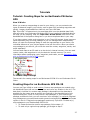
Tutorials ......................................................................................................27
Tutorial: Creating Maps for an Earthmate PN-Series GPS..................................27
Creating Maps for an Earthmate GPS PN-20 ...................................................27
Creating Maps for an Earthmate GPS PN-40 ...................................................32
Tutorial: Exchanging Data with an Earthmate PN-Series GPS ............................36
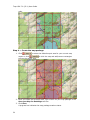
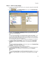
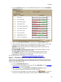
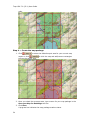
Tutorial: Downloading Imagery ....................................................................38
Tutorial: Creating a Route ...........................................................................42
Tutorial: Converting Tracks into Trails ...........................................................44
Tutorial: Using MapShare ............................................................................48
Tutorial: Flying in 3-D .................................................................................54
Map Legend .................................................................................................59
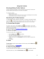
Using the Toolbar..........................................................................................63
Showing/Hiding Toolbar Options ...................................................................63
Reordering the Toolbar Options ....................................................................63
iii
Topo USA 7.0 (SP 1) User Guide
To Create New Projects ...............................................................................63
To Save a Project .......................................................................................63
To Print.....................................................................................................63
To Print the Map Screen ..............................................................................63
To Share Maps ...........................................................................................64
To Share Online With Eartha Community Atlas................................................64
To Create a Route ......................................................................................64
To Start/Stop Your GPS Connection ..............................................................65
To Exchange Files with a GPS or PDA ............................................................65
To Add Images and Data to a GPS Location....................................................65
To Grab and Pan the Map ............................................................................65
To Create a Profile......................................................................................65
To Measure Distance...................................................................................66
To Get Information About a Location .............................................................66
To Open the Options Dialog Box ...................................................................67
Customizing the Map and Tab Display ..............................................................69
Display Options Overview ............................................................................69
Resizing the Map and Tab Areas ...................................................................69
Viewing Two Maps Simultaneously ................................................................71
Showing Hybrid Maps..................................................................................72
Changing the Map Colors.............................................................................72
Changing the Map Magnification Level ...........................................................73
Changing How POIs Display on the Map.........................................................73
Displaying Basic Map Features......................................................................74
Customizing the Map Feature Preferences ......................................................77
Changing the Contour Details Preferences......................................................78
Setting Units of Measure Preferences ............................................................78
Showing or Hiding Tabs...............................................................................80
Importing/Exporting Tab Manager Preferences ...............................................81
Reordering the Tabs ...................................................................................82
Using Keyboard Shortcuts ..............................................................................85
Selecting a Keyboard Shortcut Scheme .........................................................85
Creating a New Custom Scheme ...................................................................85
Assigning Keyboard Shortcuts in a Custom Scheme.........................................85
Customizing a DeLorme Scheme...................................................................87
Renaming a Custom Scheme........................................................................87
Deleting a Custom Scheme ..........................................................................88
Importing a Custom Scheme........................................................................88
Exporting a Custom Scheme ........................................................................88
Searching For Commands ............................................................................89
Viewing All of the Shortcut Keys for a Scheme................................................89
iv
Table Of Contents
Viewing and Connecting Imagery and Data .......................................................91
Connecting Data to Topo USA ......................................................................91
Viewing Data in Topo USA ...........................................................................91
Saving Topo USA Data to Your Hard Drive .....................................................92
Creating, Editing, and Saving Projects..............................................................93
Map Files Overview.....................................................................................93
Creating and Deleting Projects .....................................................................93
Opening an Existing Project .........................................................................94
Editing a Project.........................................................................................95
Saving a Project.........................................................................................95
Creating Transfer Files ................................................................................96
Importing Transfer Files ..............................................................................98
E-mailing a Transfer File..............................................................................98
Finding a Location on the Map....................................................................... 101
Performing a Basic Search ......................................................................... 101
Performing an Advanced Search ................................................................. 102
Performing a POI Search ........................................................................... 105
Finding a Symbol by its Name .................................................................... 106
Tips on Viewing Search Results .................................................................. 106
Keywords for Category Searches ................................................................ 107
MapTags: Converting, Moving, Hiding, and Deleting ...................................... 110
Using Address Book Contacts........................................................................ 113
Searching for Address Book Contacts .......................................................... 113
Importing Existing Address Book Information ............................................... 113
Manually Entering Address Book Information ................................................ 114
Centering the Map on an Address Book Contact ............................................ 114
Editing a Contact In Your Address Book ....................................................... 115
Manually Moving a Contact's Location On the Map ......................................... 115
Deleting a Contact In Your Address Book ..................................................... 116
Showing/Hiding Address Book Contacts on the Map....................................... 116
Deleting Your Entire Address Book .............................................................. 116
Exporting Your Address Book ..................................................................... 117
Relocating Address Book Contacts .............................................................. 117
Printing ..................................................................................................... 119
Printing a Map ......................................................................................... 119
Printing a Route and Directions .................................................................. 120
Printing a Profile....................................................................................... 121
Adding Text or Graphics to Your Map........................................................... 122
Aligning Text and Graphic Items on Your Map............................................... 124
Snapping Text and Graphic Items on Your Map ............................................. 125
Layering Multiple Text and Graphic Items on a Printed Map ............................ 126
v
Topo USA 7.0 (SP 1) User Guide
Changing the Background Color of a Printed Map .......................................... 126
Manually Assembling a Multi-page Map........................................................ 127
Using the Draw Tools................................................................................... 131
Draw Overview ........................................................................................ 131
Viewing Hidden Draw Tools........................................................................ 134
Geocaching Features................................................................................. 134
Draw File Management.............................................................................. 135
Creating a New Draw File .......................................................................... 135
Saving a Draw File.................................................................................... 136
Deleting a Draw File ................................................................................. 136
Hiding Draw Files ..................................................................................... 136
Editing/Locking Draw Files ......................................................................... 137
Exporting Draw Files to Text Files ............................................................... 137
Exporting Track Data Files to Text Files ....................................................... 138
Exporting Track or Waypoint Files to GPX Files ............................................. 139
Importing Files to Draw Files...................................................................... 139
Formatting a Text File to Import as a Draw File ............................................ 141
Copying a Map Line to a Draw File .............................................................. 143
Saving a Track as a GPS Log...................................................................... 143
Viewing the Contents of a Draw File ............................................................ 143
Copying a Draw File.................................................................................. 145
Changing Draw Object Types ..................................................................... 145
Creating a Direct Route from a Line Object .................................................. 146
Copying a Draw Object From One Draw File to Another.................................. 147
Moving a Draw Object to a Different Draw File .............................................. 147
Using Draw Objects .................................................................................. 148
Copying and Placing Draw Objects .............................................................. 148
Moving Draw Objects ................................................................................ 149
Renaming a Draw Object ........................................................................... 150
Deleting Draw Objects .............................................................................. 150
Snapping Draw Objects ............................................................................. 152
Adding Points to Draw Objects ................................................................... 153
Deleting Points and Line Segments from Draw Objects .................................. 153
Labeling a Draw Object ............................................................................. 154
Routable Roads, Trails, Tracks, Lines, Arcs , and Splines ................................ 154
Drawing Routable Roads or Trails on the Map ............................................... 154
Drawing a Line, Arc, or Spline on the Map.................................................... 155
Drawing a Track on the Map ...................................................................... 156
Editing a Routable Road, Routable Trail, Line, Arc, or Spline ........................... 157
Editing a Track......................................................................................... 158
Placing a Routable Road, Routable Trail, Line, Arc, or Spline at a Specific Location
............................................................................................................. 159
Joining and Breaking Linear Objects ............................................................ 160
vi
Table Of Contents
Circles, Rectangles, and Polygons ............................................................... 161
Drawing a Circle, Rectangle, or Polygon on the Map ...................................... 161
Editing a Circle, Rectangle, or Polygon......................................................... 162
Placing a Circle, Rectangle, or Polygon on the Map ........................................ 163
Waypoints, Symbols, MapNotes, Text Labels, and Images .............................. 163
Adding a Waypoint, Symbol, MapNote, Text Label, or Image to the Map........... 163
Editing a Waypoint, Symbol, MapNote, Text Label, or Image .......................... 165
Placing a Waypoint, Symbol, Text Label, or Image at a Specific Location .......... 166
Moving and Deleting Draw MapNotes........................................................... 166
Custom Symbols ...................................................................................... 168
Custom Symbols Overview ........................................................................ 168
Creating a New Symbol ............................................................................. 168
Assigning a Waypoint ID to a Custom Symbol............................................... 169
Editing a Symbol ...................................................................................... 170
Finding a Custom Symbol .......................................................................... 170
Importing a Bitmap .................................................................................. 171
Copying and Pasting ................................................................................. 172
Pasting a Bitmap into XSym ....................................................................... 173
Dragging a Bitmap into XSym .................................................................... 174
Removing a Symbol.................................................................................. 175
Draw Tool Box ......................................................................................... 175
Using the Transparency Option................................................................... 176
Anchor Position ........................................................................................ 176
Cursor Position ........................................................................................ 177
Creating a New Symbol Set ....................................................................... 177
Opening a Symbol Set .............................................................................. 178
Profiling Linear Objects ................................................................................ 179
Creating a Profile ..................................................................................... 179
Viewing the Profile Elevation Graphs ........................................................... 180
Statistical Data ........................................................................................ 182
Manually Setting Minimum and Maximum Elevation ....................................... 185
Clearing a Profile ...................................................................................... 186
User Profile Data ...................................................................................... 186
Viewing Your Map in 3-D .............................................................................. 189
Viewing a 3-D Map ................................................................................... 189
Flying Over a 3-D Map .............................................................................. 191
Setting Your 3-D Map Preferences............................................................... 192
Routing ..................................................................................................... 193
Creating a Route ...................................................................................... 193
Adding and Inserting Stops and Vias ........................................................... 195
Changing the Routing Methods ................................................................... 197
Viewing Route Directions ........................................................................... 197
vii
Topo USA 7.0 (SP 1) User Guide
Avoiding a Specified Area When Routing ...................................................... 198
Saving Route Directions as Text ................................................................. 199
Setting Your Routing Preferences................................................................ 199
Editing a Route ........................................................................................ 200
Editing Roads .......................................................................................... 201
Labeling a Route Point with a MapNote ........................................................ 202
Moving Route MapNotes ............................................................................ 202
Displaying and Centering Routes on the Map ................................................ 203
Saving a Route ........................................................................................ 203
Deleting a Route ...................................................................................... 204
Importing Routes ..................................................................................... 204
Converting a Route to a GPS Log ................................................................ 205
Using GPS.................................................................................................. 207
GPS Overview .......................................................................................... 207
Initializing GPS ........................................................................................ 207
Tracking a Route with GPS......................................................................... 210
Getting Back on Track When Off Course ...................................................... 211
Panning the Map Automatically While GPS Tracking ....................................... 211
Playing Back a Log File.............................................................................. 212
Previewing a GPS Log File.......................................................................... 213
Viewing File Details for a GPS Log............................................................... 214
Monitoring Your GPS Status ....................................................................... 215
Monitoring GPS Satellite Information ........................................................... 216
Viewing Sun and Moon Information............................................................. 217
About GPS............................................................................................... 218
Using Handheld Devices ............................................................................... 221
Handheld Export ...................................................................................... 221
Creating a Map Package ............................................................................ 221
Setting Your Handheld Export Preferences ................................................... 222
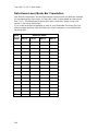
Data Zoom Level/Scale Bar Translation ....................................................... 224
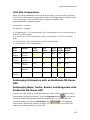
Grid Size Comparisons .............................................................................. 225
Exchanging Information with an Earthmate PN-Series GPS ............................. 225
Exchanging Maps, Tracks, Routes, and Waypoints with Earthmate PN-Series GPS
............................................................................................................. 225
Enabling Earthmate PN-Series GPS Exchange Features in Topo USA ................ 226
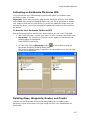
Activating an Earthmate PN-Series GPS ....................................................... 227
Deleting Maps, Waypoints, Routes, and Tracks ............................................. 227
Sending/Receiving Maps to/from an Earthmate PN-40 ................................... 228
Sending/Receiving Routes to/from an Earthmate PN-40 ................................. 230
Sending/Receiving Tracks to/from Earthmate PN-40...................................... 231
Sending/Receiving Waypoints to/from Earthmate PN-40 ................................ 233
Sending Draw Layers to an Earthmate PN-40 ............................................... 234
Firmware Updates for the Earthmate PN-40 ................................................. 235
viii
Table Of Contents
Sending/Receiving Maps to/From an Earthmate PN-20................................... 235
Sending/Receiving Routes to/from an Earthmate PN-20 ................................. 237
Sending/Receiving Tracks to/from Earthmate PN-20...................................... 239
Sending/Receiving Waypoints to/from Earthmate PN-20 ................................ 240
Sending Draw Layers to an Earthmate PN-20 ............................................... 241
Firmware Updates for the Earthmate PN-20 ................................................. 242
States Included in Regional Map Packages ................................................... 242
Exchanging Information with a Third-party GPS Device .................................. 243
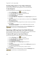
Sending Route Information to a Third-party GPS Device................................. 243
Sending Tracks to Your Third-party GPS Device ............................................ 244
Sending Waypoints to Your Third-party GPS Device....................................... 245
Receiving a Route From Your Third-party GPS Device .................................... 245
Receiving a Track From Your Third-party GPS Device..................................... 246
Receiving Waypoints From Your Third-party GPS Device ................................ 247
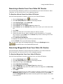
Exchanging Information with a Palm OS Device ............................................ 248
Sending a Handheld Map to a Palm OS Device .............................................. 248
Sending Route Information to Your Palm OS Device ...................................... 249
Sending Waypoints to Your Palm OS Device ................................................. 250
Receiving a GPS Log From Your Palm OS Device ........................................... 250
Receiving a Route From Your Palm OS® Device............................................. 251
Receiving Waypoints From Your Palm OS® Device ......................................... 251
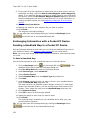
Exchanging Information with a Pocket PC Device .......................................... 252
Sending a Handheld Map to a Pocket PC Device ............................................ 252
Sending Route Information to Your Pocket PC Device .................................... 253
Receiving a GPS Log From Your Pocket PC Device ......................................... 254
Sending Waypoints to Your Pocket PC Device ............................................... 254
Sending a GPS Log to Your Pocket PC Device................................................ 255
Receiving a Route From Your Pocket PC Device............................................. 255
Receiving Waypoints From Your Pocket PC Device ......................................... 256
Using NetLink ............................................................................................. 257
NetLink Overview ..................................................................................... 257
Using GeoTagger ........................................................................................ 259
Getting Started with GeoTagger ................................................................. 259
Tagging an Image .................................................................................... 259
Tagging Data ........................................................................................... 260
Calculate the Timestamp Offset .................................................................. 261
Sharing Online............................................................................................ 263
Using Eartha Community Atlas ................................................................... 263
Using MapShare ....................................................................................... 263
Recreational and Travel Contact Information ................................................... 265
Road Condition/Construction Contact Information ......................................... 265
Hotel, Car, and Airline Contact Information .................................................. 269
ix
Topo USA 7.0 (SP 1) User Guide
Recreational Contacts ............................................................................... 272
Legal Information........................................................................................ 279
DeLorme Topo USA 7.0 Single-User License Agreement ................................. 279
Apache Software License, Version 1.1 ......................................................... 282
Index ........................................................................................................ 285
x
Getting Started
Welcome to Topo USA
These are just some of the many features that you can enjoy with Topo USA®.
•
Download $40 worth of data with Data Download Dollars, FREE Publicly
Managed Lands data, and FREE Game Management District data (registration
required). You can also subscribe to the DeLorme Map Library for unlimited
downloads.
•
Map Library subscriptions allow you to download unlimited data and imagery
for just $29.99 a year.
•
Exchange maps, tracks, routes, and waypoints with an Earthmate PN-Series
GPS.
•
Search for trails, state parks, mountain peaks, unique natural features, points
of interest, and more.
•
View your maps in 3-D and fly over the terrain with shaded relief, detailed
land use/land cover features, and elevation contours.
•
Send highly detailed Topo USA and aerial imagery to a handheld device, such
as an Earthmate PN-Series GPS device, using the Handheld Export tab.
•
Use the split-screen functionality to view two types of data for the same
location at the same time.
•
Create trail, road, or direct routes by adding start and finish points on your
map. Customize your route by adding stops and vias.
•
Use the toolbar to share maps, add data and images to the map,
open/create/save map files, start/stop GPS, edit your preferences, and more.
•
Profile map items and objects you draw/add to the map to determine
coordinate information, linear distance, elevation, grade, and so on.
•
Send/receive tracks, waypoints, and routes to or from your Earthmate PNSeries GPS or other compatible GPS device.
•
Print high quality, detailed, 2-D or 3-D single-page maps, and/or mural maps
as large as 3 x 3 pages. You can even print your routes, route directions, and
profiles.
•
Import .loc files from www.rgeocaching.com to help find a cache location and
import .gpx files to include comments in the Draw tab that you can transfer to
an Earthmate PN-Series GPS
•
Create custom keyrboard shortcuts or select a DeLorme shortcut scheme,
such as 3-D Navigation, to navigate the program more easily than ever.
•
Connect your GPS device to the program and track your progress on a laptop
as you travel.
•
Use the Measure tool to measure linear distance or the area and perimeter of
a polygon measurement object on the map.
•
And much more!
1
Topo USA 7.0 (SP 1) User Guide
What's New in Topo USA
2
•
GeoTagger, a new toolbar feature, provides updated image and data tagging
features — allows you to combine digital photos or data with GPS locations in
a completely new way.
•
Toolbar access to the Eartha Community Atlas (ECA) wizard. ECA is a new
geographic social-networking website where you can share your map data
with others.
•
Hybrid Map option allows you to view roads, contours, and points above
imagery in the secondary map.
•
Includes four million searchable places of interest from Street Atlas USA® —
ideal for use on an Earthmate PN-Series GPS device.
•
Includes points of interest from the DeLorme Atlas & Gazetteer™ paper
series, including boat ramps, campgrounds, unique natural features and much
more.
•
Includes advanced Find features for searching by category using keywords
without having to narrow location.
•
Includes $40 of Data Download Dollars for all available datasets, including
USGS Quads, NOAA Nautical Charts, and color high-resolution imagery.
Datasets now available for individual purchase, allowing you to mix and
match a variety of data. Downloads require the use of NetLink.
•
Includes a bonus DVD dataset of Topo USA 7.0® precut maps at all
magnification levels for use on an Earthmate PN-Series GPS device — cutting
maps from the desktop no longer required.
Note Topo USA 7.0 uses a new file format for Earthmate PN-Series GPS
devices to improve Find and map cutting accuracy. You will need to re-cut
map packages you created in Topo USA 6.0 with Topo USA 7.0 to ensure
routing integrity, as well as to access new POIs and data described above.
•
You can refine your route by choosing the type of route you are creating —
for driving, cycling, or hiking — includes appropriate speed and time settings.
•
Supports popular wrist athletic devices from Timex®, Garmin™, and
Suunto®. Download tracks and see your heart-rate information and other
data points on the track and in the Profile tab. Note Some wrist computers
include built-in GPS and some require a separate GPS receiver, such as an
Earthmate PN-Series GPS device.
•
Includes improved Handheld Export tab that allows you to adjust grid sizes
for sending information to an Earthmate PN-Series GPS.
•
Includes option to sort columns of data in the File area of the Draw tab. Also
includes ability to import comments from a .gpx file to the Draw tab
Comments column, edit column text, and transfer text to an Earthmate PNSeries GPS device.
•
Supports the Windows Vista™ operating system, including recent model
Intel® chipset personal computers.
•
Includes option to turn off data connections in the Map Files tab.
•
Includes improved Info tab information for tracks.
Getting Started
Frequently Asked Questions
These questions are asked most frequently by our customers.
•
How do I enable Earthmate PN-Series GPS device exchange features in Topo
USA®?
During the product installation, you were give the option to select each
Earthmate® PN-Series GPS you own. If you did not select a device and you
do own an Earthmate PN-Series GPS, you can enable the exchange features
in Topo USA® using the Help menu. You must enable the exchange features
to send and receive maps, waypoints, tracks, and routes to and from your
device.
You must also activate your device.
To Enable Earthmate PN-Series GPS Exchange Features in Topo
USA
Use the following steps to enable the exchange features in Topo USA.
1. From the Topo USA Help menu, click Enable Earthmate PN-Series
GPS Exchange Features.
2. If you have not enabled Topo USA, the following message displays,
"Would you like to use Topo USA 7.0 to send/receive maps, waypoints,
tracks, and routes to/from an Earthmate PN-Series GPS?"
Click Yes to enable the exchange features.
OR
If you have already enabled Topo USA, the following message
displays, "Topo USA 7.0 has already been updated to include the
Earthmate PN-Series GPS features."
Click OK.
3. Restart Topo USA.
•
How do I activate an Earthmate PN-Series device in Topo USA?
You must activate your Earthmate® PN-Series GPS before you transfer maps,
waypoints, tracks, or routes.
To Activate Your Earthmate PN-Series GPS
Use the following steps to activate your device before you use it with Topo
USA®.
1. With Topo USA open, connect your device to your computer and power
it on.
2. PN-40 only: The Connect to Computer screen appears on the device
and Data Exchange is highlighted.
Press ENTER on the device.
in the toolbar to open
3. In Topo USA, click the Exchange button
the Earthmate PN-Series Exchange Dialog box.
The device is activated when it appears in the drop-down list in the top
right corner of the dialog box.
3
Topo USA 7.0 (SP 1) User Guide
•
How do I get maps from Topo USA® to my Earthmate PN-Series GPS device?
To get started, see these tutorials:
Tutorial: Creating Maps for an Earthmate PN-Series GPS
Tutorial: Exchanging Data with an Earthmate-PN Series GPS
For more information, see the PN-Series GPS Help topics under Using
Handheld Devices.
•
Is my GPS device supported?
DeLorme software interfaces with different GPS devices as outlined below.
•
DeLorme GPS Devices: Any DeLorme GPS will interface with a current
DeLorme software release.
•
USB GPS Support: DeLorme software can use the data output from a
USB GPS if the device meets one of the following criteria:
•
When the GPS is attached to the computer, it is recognized and
displayed under Ports in the Microsoft® Windows® Device
Manager.
•
The unit is a Garmin USB device and the Garmin drivers are
installed.
Note Magellan USB devices are not currently supported.
•
•
Serial GPS Support: DeLorme software can use the data output from a
serial GPS device. The device must be connected to a free COM port
and output a generic NMEA (National Marine Electronics Association)
stream.
•
Bluetooth GPS Support: DeLorme software can use the data output
from a Bluetooth GPS device. You must configure your Bluetooth
software to create a virtual serial port.
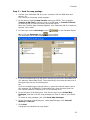
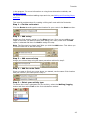
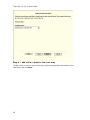
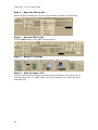
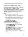
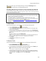
How do I import files from an earlier version of Topo USA into this version?
Use the Map Files tab to import projects, routes, and draw files from many
other DeLorme mapping programs.
To Open A Project
1. Click the Map Files tab.
2. Click File and then click Open.
3. Select the project you want to view and then click Open.
4. Click OK.
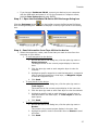
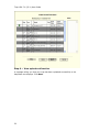
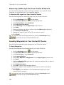
To Import a Route
5. Click the Map Files tab.
6. Click Add and then click Route Files. The Add Data to Maps dialog
box displays.
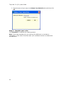
7. Browse to the desired file, select it, and then click Add. The route is
added to the current project.
To Import a Draw File
8. Click the Map Files tab.
9. Click Add and then click Draw Files. The Add Data to Maps dialog box
displays.
4
Getting Started
10. Browse to the desired file, select it, and then click Add. The draw file
is added to the current project.
•
How do I find a specific location?
Use Topo USA's powerful search tools to locate any place in the United States.
In addition, you can search for places along your route, within a certain radius
of the current map center, or within a particular region.
To access the search features in Topo USA, click the Find tab. For more
information on searching for specific locations, see Performing a Basic Search
and/or Performing an Advanced Search.
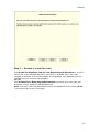
•
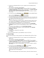
How do I perform an Along the Way search in the Find tab and print my
results?
Search for names or categories along your current route by performing an
advanced search in the Find tab. You can then print your search results using
the Along the Way print option.
Use the following steps to search for a name/category along your current
route and print the results:
1. Click the Find tab and then click Advanced. The Advanced dialog area
displays.
2. Select Category from the From drop-down list.
3. Select CurrentRoute from the Within drop-down list.
4. Type the appropriate keyword in the Keywords text box.
5. Type the distance in the Distance text box.
6. Click Search.
The search results display in the dialog area.
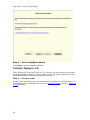
7. Click the Print tab and then click Route. The Route dialog area
displays.
8. Select the Along the Way check box.
9. Click Print Now.
The search results print.
•
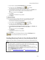
How can I run Topo USA without having to use DVD to access data?
You can save Topo USA data to your computer's hard drive so that it is readily
available when you need it. For more information, see Saving Topo USA Data
to Your Hard Drive.
•
How do I submit a data update or fix the roads on my map?
•
If you find there is a missing local road, you can add it to the current
Draw layer using the Routable Roads Draw tool. For more information,
see Drawing Routable Roads or Trails on the Map.
•
To report an error to us:
1. Click the NetLink tab.
2. Click the Corrections subtab.
3. Click the Map Correction link.
4. Use the Customer Revisions wizard to submit the change.
5
Topo USA 7.0 (SP 1) User Guide
•
How do I initialize my GPS receiver?
Each time you use your GPS receiver, you initialize it, which means you set
your starting position on the map by obtaining the initial coordinates of your
location. This can be done automatically or manually.
For more information, see Initializing GPS.
•
What is a project?
You can save all of your work as a single workspace so you can open it again
later. These saved workspaces are called projects.
A project consists of the following items: coordinates of the map center,
current zoom level, current magnification, map display preferences, any
added items: such as draw layers, routes, and so on. As you create new
routes or draw layers, change preferences or the map center, and so on, they
are added to the current project. You can save or discard changes.
To learn how to create a project, see Creating and Deleting Projects.
•
What do the different colors and symbols on the map mean?
The different colors on the map represent different areas of land use and land
cover (for example, parks, population centers, water, forests, and so on). The
Map Legend provides examples and descriptions of the map features.
To view the Map Legend, click the Help button
Map Legend.
•
on the toolbar and click
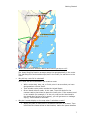
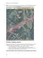
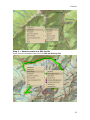
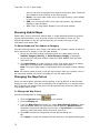
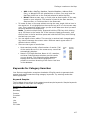
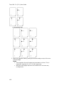
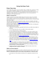
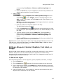
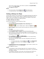
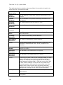
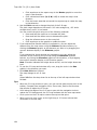
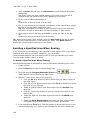
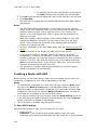
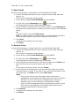
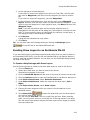
What is the difference between a stop and a via?
When routing in Topo USA, you have the option of adding/inserting stops or
vias in the route. A stop is a location in a route where you want to stop and
then proceed from. A via is a location on the map that you want the route to
use.
For example, if you create a route between Portland, Maine, and Yarmouth,
Maine, with no stops or vias, the route directions will tell you to take I-295.
However, if you want to take US Route 1 instead, you can place vias in the
route on US Route 1 to force the route to go by way of US Route 1. If you
plan on stopping in Falmouth Foreside for lunch, you will want your route
directions to reflect that stop. When you add a stop, you can recalculate to
include it.
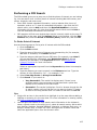
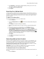
This map shows the area between Portland, Maine, and Yarmouth, Maine,
with two vias and one stop.
6
Getting Started
•
What's the difference between adding and inserting a stop or via?
The Insert Stop/Via function arranges stops/vias geographically in the route.
The Add Stop/Via function adds stops/vias in the order you add them to the
route.
•
Why did my route fail to calculate?
Your route will fail to calculate if you create a route:
•
•
With a route start, stop, via, or finish point in an area that you have
designated as a Route Avoid.
•
That includes route points outside the United States.
•
On an island without roads. In this case, Topo USA looks for the
nearest road to that island to place the route point. If the nearest road
is not routable (for example, it is the only road on the island and/or
the island does not have ferry access), you will get an error message
saying, "Route failed to calculate."
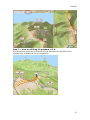
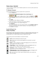
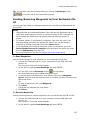
Why do X marks display on the map when I calculate a route?
•
When you place a route point in a location that isn't on a street, Topo
USA finds the closest street to that location, marks the space between
7
Topo USA 7.0 (SP 1) User Guide
the point you clicked and the street with X marks, and starts the route
at the street.
•
•
If you search for an address that is on a walkway and place a route
point on it, Topo USA finds the closest street to that location, marks
the space between the point the clicked and the street with X marks,
and starts the route at the street.
Why is the tab area and control panel so narrow?
Topo USA was designed to accommodate resolutions of 800 x 600 or higher.
If you are using a very high resolution (such as 1920x 1200), the tab area
and control panel may appear to be very narrow. You can modify the size of
the map and tab area or use the Windows Control Panel to adjust your display
settings.
•
What's the best way to measure the distance of a road or trail?
The best way to determine the distance of a particular road or trail is to
create a route. You can create a route using right-click functionality, the
toolbar, or the Route tab. For more information, see Creating a Route.
•
What's the best way to measure a large area on the map?
The best way to measure a large area on the map is with the area tools in the
Draw tab (such as the polygon tool). When you draw an area object on the
map, the area displays next to the object on the map. If you click off the
object, you can view the area again by clicking the Select tool in the Draw
tab and then clicking the area object on the map. For more information about
drawing area objects, see Drawing a Circle, Rectangle, or Polygon on the Map.
•
What's the best way to measure a short distance on the map?
The best way to measure a short distance (that is not made up of a
on the toolbar. You can
road/trail) on the map is to use the Measure tool
measure linear distance and area on the map based on the units chosen in
the Display tab of the Options dialog box. For instructions on using the
measure tool, see Measuring Distance and Area.
•
Why won't 3-D billboards display?
If you receive a message saying that 3-D billboards cannot be displayed,
ensure that you have a 32 MB video card with the most recent drivers and
that it supports DirectX and transparencies.
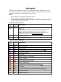
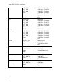
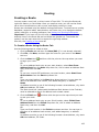
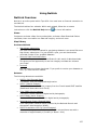
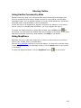
Helpful Tips
These tips may help you use the various features in Topo USA®. The Did You
Know? pop-up tutorials provide hints while you are working in the application.
Tips
8
•
To disable a specific pop-up tutorial, select the Don't Show Again check box
before you close it.
•
To disable all pop-up tutorials, click the Help button
click Shut Off All Pop-up Tutorials.
on the toolbar and
Getting Started
•
To enable all pop-tutorials after you have shut off one or more, click the Help
button on the toolbar and click Reset All Pop-up Tutorials.
Control Panel
If you want to...
Use this tip...
Zoom the map out/in
quickly
Drag the map cursor in an up-left direction to zoom
the map out or drag it in a down-right direction to
zoom the map in.
Pan the map quickly
Position your cursor on the edge of the map; it
becomes a white hand that you can use to drag the
map to the new location.
Update the coordinate
format that displays in
the Control Panel
Update your measurement preferences at any time
using the Display tab in the Options dialog box.
View the last map center
Press the middle button in the Compass Rose in the
Control Panel to center the map on the previous map
view. This button performs an undo function for the
last pan or zoom (up to 256 times).
Measurement Tool
If you want to...
Use this tip...
Measure the
area/perimeter of a
specified location on the
map
Use the measure tool to draw a polygon on the map
and determine its area and perimeter. Just click pointby-point to draw the polygon on the map and then
double-click to close the polygon. The area and
perimeter display in the center of the polygon.
Tab Area
If you want to...
Use this tip...
Adjust the size of the
tab area
Adjust the size of the tab area by dragging the top or
right side of the tab area.
Show, hide, or reorder
tabs
Use the Tab Manager option in the Help menu to
show, hide, or reorder tabs.
Import or export a tab
configuration file
Use the Tab Manager option in the Help menu to
import or export a tab configuration file.
Map Area
If you want to...
Use this tip...
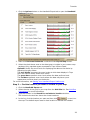
Know the best data
zoom level to view
certain datasets
Click the Options button in the toolbar to open the
Options dialog box, and then click the Handheld tab.
The green range in the Zoom Range sliders next to
each type of data show the best data zoom level
range for that data.
9
Topo USA 7.0 (SP 1) User Guide
Map Display Settings
If you want to...
Use this tip...
Know the best map
feature options to
display with Street Map
Colors
Street Map Colors are best viewed when Contours,
Shaded Relief, and Land Cover are turned off. Use the
Map Features tab in the Options dialog box to clear
these features.
Map Files
If you want to...
Use this tip...
Learn how to add route
and/or draw layers to
your Project
To add existing route and/or draw files to your
project, click the Add button and select the Draw
File or Route File option.
Find
If you want to...
Use this tip...
Modify a Find search
result
Right-click a result item in the Find tab to add it as a
MapNote, insert it as a stop in your route, copy the
information to your clipboard, and so on.
Print
If you want to...
Use this tip...
Stop a page in a multipage map from printing
If you do not want to print all the pages in a multipage map, click each page you do not want to print on
the Layout graphic.
Draw
If you want to...
Use this tip...
Create a route using a
road or trail you have
added to the map with
the Draw tab
When you draw a routable road/trail, click each
existing road it crosses to ensure that you can route
on the new road/trail. When you open a track you've
imported from your GPS device, to join the imported
line with existing lines, right-click each intersection
and click Manage Draw/Join.
GPS
If you want to...
Use this tip...
View a GPS log on the
map
Use the Draw tab to import a GPS log file and view it
as a line object on the map.
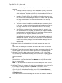
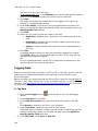
Route
If you want to...
Use this tip...
Reorder inserted stops
Reorder your inserted route stops using the Advanced
features in the Route tab.
10
Getting Started
Create a route quickly
For quick route creation, right-click the map and
select one of the Create Route options or use the
Route buttons on the toolbar.
Reorder the columns in
the Route Directions list
Click the Directions list column headers to change
the column order.
Determine the difference
between adding and
inserting stops and vias
Added stops/vias are placed in the order you add
them to the route. Inserted stops/vias are placed in
the order you would approach them between the Start
and Finish points of the route.
View information about
your second turn
Click the Show Turns button when GPS tracking to
view information about the following turn.
Info
If you want to...
Use this tip...
Quickly view information
for a location on the
map.
Hover your cursor over objects on the map to see
information (such as road names, city/town, details
about draw objects, etc.) in the status line that
appears at the bottom of the map, just above the tab
area.
Handheld Export
If you want to...
Use this tip...
Modify the export area
in Handheld Export
When you click Preview, the default export area for
the location you selected displays on the map as
shaded rectangles. Click Select to confirm the area.
To edit the area, click the Select/Edit tool and then
click the map to add or remove rectangles to/from the
export area.
11
Topo USA 7.0 (SP 1) User Guide
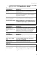
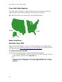
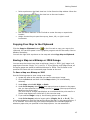
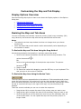
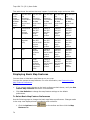
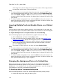
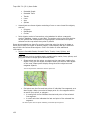
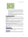
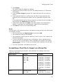
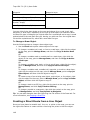
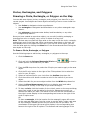
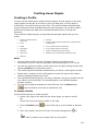
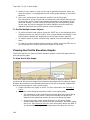
Topo USA Data Regions
Topo USA® data is available on DVD; the National version includes all states. The
states included in the Eastern and Western versions are shown below.
Tip Install the data to your hard drive for improved performance.
Basic Functions
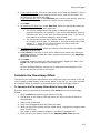
Running Topo USA
After you install the program, you can run it with the DVD to use the data without
installing it to your computer's hard drive. For more information on installing data to
your hard drive, see Saving Topo USA® Data to Your Hard Drive.
To Access Data from the DVD
Choose one of the following ways to access the data using the DVD.
•
If you installed a desktop shortcut, insert a the Topo USA DVD into your DVD
drive and then double-click the Topo USA icon.
OR
•
12
Insert a Topo USA DVD into your DVD drive. From the Start menu, point to
Programs, point to DeLorme, point to Topo USA 7.0, and then click Topo
USA 7.0.
Getting Started
Zooming In and Out
You can use the drag and zoom feature, zoom tools, or the data zoom level (Data
zoom level is the relationship between what you see in a map view and how it exists
in reality. It is the amount of geographic data displayed on a computer monitor. The
data zoom level is similar to the traditional fractional relationship expressed on paper
maps. For example, 1:24,000, 1:100,000, 1:500,000, and so on.) to quickly change
the zoom level of the map view.
Notes
•
Increasing the data zoom level number shows a smaller geographic area at
greater detail.
•
Decreasing the data zoom level number shows a larger geographic area at
lesser detail.
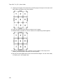
•
If you view both the right (primary) and left (secondary) maps at different
data zoom levels, a box (or lines, depending on the current data zoom level)
displays on the map that is zoomed out the furthest. The box/lines indicate
the area that is in view on the other map.
•
If you view the right and left maps at the same data zoom level but they are
not equally represented on the screen (50/50), a box (or lines) displays on
the map that is covering the most screen area. The box/lines indicate the
area that is in view on the other map.
To Drag and Zoom In
Use the following steps to zoom in either the right or left map.
1. Click and hold down the left mouse button as you drag the mouse in a downright direction on the map to encompass the area you want to display. A view
box displays on the screen and changes dimension as you move the mouse. A
label displays the data zoom level at the current map center.
2. Once you reach the map area or data zoom level you want to display, release
the mouse button. The area you selected fills the map window, the map recenters, and the map view adjusts to show the appropriate level of detail.
Tip You can move the view box to another location by pressing the SHIFT
key at anytime during this procedure.
To Drag and Zoom Out
Use the following steps to zoom in either the right or left map.
1. Click and hold down the left mouse button as you drag the mouse in an upleft direction on the map. A staircase with a small circle displays on the
screen.
2. Continue dragging the mouse in an up-left direction. The small circle moves
up the steps, one step per data zoom level. A label displays the data zoom
level to the bottom-right of the staircase.
3. Once you reach the data zoom level you want to display, release the mouse
button. The map view adjusts to display the appropriate level of detail. The
map center is retained on your screen.
13
Topo USA 7.0 (SP 1) User Guide
To Zoom In/Out Using the Zoom Tools
There are two sets of zoom tools. The zoom tools for the right map are located in the
control panel. The zoom tools for the left map are located at the top of the left map
view.
Click the up arrow to zoom out one minor data zoom
level at a time. Click the down arrow to zoom in one
minor data zoom level at a time.
Right
Map
Controls
Click the Zoom In 1 tool to increase the detail
number to the next full level.
Click the Zoom Out 1 tool to decrease the detail
number to the next full level.
Click the Zoom Out 3 tool to decrease the detail
number by three full levels.
Left
Map
Controls
Click the plus button to increase the detail number to
the next full level.
Click the minus button to decrease the detail number
to the next full level.
The data zoom level of the left map displays in the
text area to the left of the buttons.
Tips
•
Press ALT+PAGE UP on your keyboard to zoom out to the next full data zoom
level. Press ALT+PAGE DOWN on your keyboard to zoom in to the next full
data zoom level.
•
Use the mouse wheel (if available) to zoom the map in and out. Rotate the
mouse wheel to zoom in by individual data zoom level steps or hold the SHIFT
key while rotating the mouse wheel to zoom to the next full data zoom level.
Panning/Centering the Map
Use any of the following methods to pan (move) or center the map.
14
•
Click anywhere on the current map view. The point you click becomes the
new map center.
•
When you point near the map edge, a white hand displays. Drag the hand to
move the map in that direction.
•
Click the Grab and Pan button
D map in any direction.
•
Click anywhere on the overview map. The point you click becomes the new
map center. This allows you to traverse greater distances with each mouse
click than you can within the main map.
on the toolbar to drag/pan the 2-D or 3-
Getting Started
•
Point anywhere on the black view box in the Overview Map window. When the
pointer becomes a
, drag the view box to the new location.
•
Use the search features in the Find tab to center the map on a particular
location.
•
Assign shortcut keys to pan the map up, down, left, or right in small
increments.
Copying Your Map to the Clipboard
Click the Copy to Clipboard button
on the Print tab to copy your map to the
clipboard. You can then paste it into a graphics program such as Microsoft® Paint or
Adobe® Photoshop.
You can also right-click anywhere on the map and select Copy Map to Clipboard.
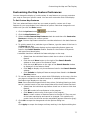
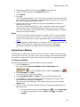
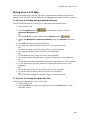
Saving a Map as a Bitmap or JPEG Image
You can save the current map view as a bitmap (.bmp) or JPEG (.jpg) image in all
page layout formats: Single, 2 x 2, and 3 x 3. If you select a multi-page format, all
the active pages are saved as individual bitmaps or JPEGs. The file name is the
specified file name with an incremental page number at the end.
To Save a Map as a Bitmap or JPEG
Use the following steps to save a map as an image.
1. Locate the area on the map that you want to save as an image.
2. Click the Print tab and then click the Map subtab (if it is not already
selected).
3. Under Map, select Left, Right, or Both.
4. Under Print Layout, select Page (the map print area is based on the paper
size you have specified in the Setup options) or Screen (the map print area is
based on the screen size).
The print area for a Page map displays as a red box and the print area for a
Screen map displays as a blue box on the overview map.
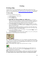
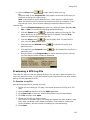
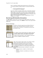
5. If you selected Page in step 4, the following options are available.
a.
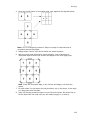
Under Print Layout, select a layout option (Single, 2 x 2, or 3 x 3). The
print area displays on both the Map and the Overview Map. In the example below, 2
x 2 is selected. This means the print area encompasses four standard pages at
whatever paper size you specified in the Setup options. You can assemble a
15
Topo USA 7.0 (SP 1) User Guide
multipage map into a large map.
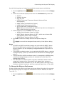
b.
Optional. If you selected 2 x 2 or 3 x 3 in step 5a and do not want to save all
the pages in the multipage map on the Map Layout graphic itself, click the page(s)
you do not want to save. The page appears dimmed or gray. In the example below,
page 4 will not print.
c.
Optional. Verify this is the location and photo zoom you want to save. If not,
pan the map to the location and zoom to the level you want.
Note Changing the photo zoom enlarges/reduces the map features and changes the
map area that you save as an image. If you increase the photo zoom level, map text,
lines, symbols, etc. are larger and your map area is reduced. If you decrease the
photo zoom level, map text, lines, symbols, etc. are smaller and your map area is
enlarged. The reduction/enlargement percentages for your photo zoom level display
under the Photo Zoom drop-down list.
d.
Optional. If you want to use other tabs and functions but not lose your
current print area, print photo zoom, or other settings, select the Lock Print Center
check box. This locks the print area and changes the tab label to red.
6. Optional. Add text or graphics to your map.
7. Optional. Select the Print Preview check box to zoom the map and view the
entire area that will be saved as a bitmap image. Clear the check box to
return to your previous data zoom level.
.
8. Click the Save button
OR
To cancel saving the file and return to the Print Map dialog area, click Cancel.
9. Type the file name in the File Name text box, select to save the file as a
.bmp or .jpg from the Save as Type drop-down list, select the DPI (dots per
inch) value (optional), and click Save. The map is saved.
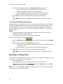
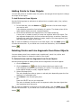
Measuring Distance and Area
Use the Measure tool
on the toolbar to measure linear distance and area on
the map based on the units chosen in the Display tab of the Options dialog box.
The snap function snaps (attaches) the point of a measurement line to a point on a
road or another measurement object. This ensures a more accurate measurement of
distance or area.
The snap function is essential when measuring area. To measure area, you must
completely enclose the area by snapping your finish point to your starting point.
16
Getting Started
Notes
•
The measure tool is the best way to measure short distances on the map. If you
want to measure the distance of a road, try creating a route. If you want to
measure a large area on the map, use the area object tools in the Draw tab.
•
To disable the auto-snap function, hold down the ALT key on your keyboard
while using the Measure tool.
•
Measure objects (lines and areas) are saved with the current project. When you
create a new project file, the measure objects do not display. If you want the
same measure objects on your new project, you must recreate them.
•
To view information about a measurement line, right-click it and select Info
from the shortcut menu. The measurement information is automatically
displayed in the Info tab.
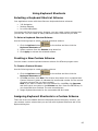
To Measure Distance or Area
Use the following steps to measure linear distance or area on the map.
1. Verify you have the correct units of measure selected in the Display tab of the
Options dialog box. For more information, see Setting Units of Measure
Preferences.
2. On the toolbar, click the Measure tool
. The pointer changes to
.
3. Click point-by-point to draw a measurement line on the map. A text box
displays next to your pointer indicating the total distance of the measurement
taken.
Note When you pass over a point in a road, measurement line, or
measurement area to which you can snap, a yellow circle defines the snap
point. Click to snap the point of the measure line to the road or measurement
object's point coordinate.
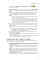
4. To end a measurement line, double-click the last point of the measurement
line.
OR
Click the last point of your measure line or area and then click the Measure
tool on the toolbar.
The measure line is a two-pixel wide yellow line and the total length of the line
is displayed in a label at each endpoint of the line.
5. To end a measure area, hover over the starting point until the yellow snap
circle displays, and then double-click the last point to the starting point. The
closure area is transparently shaded, and the area and perimeter
measurements display.
17
Topo USA 7.0 (SP 1) User Guide
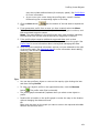
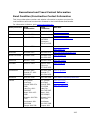
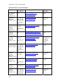
Chart of Supported Coordinate Formats
These are the supported formats for latitude/longitude, UTM/UPS, MGRS/USNG, and
SPCS searches. Sample coordinates are for Yarmouth, Maine.
Tip Examples of search formats are listed in the Advanced search drop-down text
boxes along with a history of your most current search criteria.
Coordinate
Format
QuickSearch
Advanced Search
Latitude/Longit
ude
N 43 48 30, W70 9 52
N 43 48 30
W70 9 52
N 43 48.4910, W 070
09.8440
N 43 48.4910
W 070 09.8440
N434829.4600,
W0700950.6400
N434829.4600
W0700950.6400
N43-48-30, W70-9-52
N43-48-30
W70-9-52
N 43:48:29.46, W
70:9:50.64
N 43:48:29.46
W 70:9:50.64
4348, -7009
4348
-7009
4348N, 7009W
4348N
7009W
N4348, W7009
N4348
W7009
4348n, 7009w
4348n
7009w
n4348, w7009
n4348
w7009
4348 N, 7009 W
4348 N
7009 W
N 4348, W 7009
N 4348
W 7009
4348 n, 7009 w
4348 n
7009 w
n 4348 w 7009
n 4348
w 7009
434829, -700950
434829
-700950
4348.491, -7009.844
4348.491
-7009.844
4348.491, -7009.844
4348.491
-7009.844
434829.46, -700950.64
434829.46
-700950.64
43.80818333, -70.16406667
43.80818333
-70.16406667
43 48.4910 N, 70 09 50.64 W
43 48.4910 N
70 09 50.64 W
43 48.4910 n, 70 09 50.64 w
43 48.4910 n
70 09 50.64 w
N 43 48.4910, W 70 09 50.64
N 43 48.4910
70 09 50.64 W
434829.46 N, 700950.64 W
434829.46 N
700950.64 W
43, -70
43
-70
18
Getting Started
UTM/UPS
19T 0406311E 4850964N
19T 0406311 4850964
19T / 0406311 / 4850964
MGRS/USNG
19TDJ 06354 51187
Zone:
Easting:
Northing:
19T
0406311E
4850964N
Zone:
Easting:
Northing:
19T
0406311
4850964
Zone:
Easting:
Northing:
19T
0406311
4850964
same as QuickSearch
19TDJ0635451187
(NAD27)*
19TDJ06355109
19TDJ064511
19TDJ0651
SPCS
ME-W 0500490 0355150
Zone:
Easting:
Northing:
ME-W
0500490
0355150
* Use this example for USNG with non-standard datum.
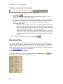
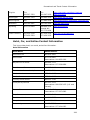
Searching Tips
When you use the Find or Route tabs to search for a location, you must enter the
information in a specific format.
Tips
•
Use punctuation as in the examples in the table below
•
Do not use periods
•
Search with the minimum amount of information to increase the number of
results. For example, if you search for Kalalau Trail in Hawaii but you are not
sure of the spelling, type "Kal, HI" and then scroll through the results until
you find a match.
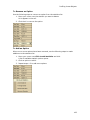
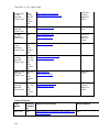
This table shows formats for search types.
For this type of
search...
Use this format...
Example
Address
Street address, City,
State
100 Baxter Blvd, Portland,
ME
Street address, ZIP Code
100 Congress St, 04101
Street address, City,
State, ZIP Code
100 Congress St,
Portland, ME 04101
City
City, State
Atlanta, Georgia
ZIP Code
##### (5-digit ZIP
Codes only)
04096
Minor Point of Interest
POI name, City, State
Wal-Mart, Columbus, OH
19
Topo USA 7.0 (SP 1) User Guide
Major Point of Interest or
Landmark
POI/landmark name
Mount Rushmore
POI/landmark name,
State
Space Needle, WA
Latitude/Longitude
See Chart of Supported of Supported Coordinate
Formats
Exiting Topo USA
To exit the program, click the Close button
screen.
in the upper-right corner of the
The Save Changes dialog box opens if you made changes to a project or projects.
•
Click Yes to save changes.
Note If only one change was made, the program closes after you save the
project.
•
Click No to discard changes and close the program.
•
Click Cancel to return to Topo USA®. No changes are saved.
If you made more than one change to the project or changes to more than one
project, once you save your project, the Exit dialog box opens.
•
Click Save and Exit to save changes to the selected files and close the
program.
Note Clear the check box for any file you do not want to save.
•
Click No to discard changes and close the program.
•
Click Cancel to return to Topo USA. No changes are saved.
About the Interface
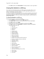
Tab Area
You can access most of the application's functions from the tab area at the bottom of
the screen. To access Help for a specific tab, click the Help button
•
Map Files
•
Find
•
Print
•
Draw
•
GPS
•
Route
•
Profile
•
3-D
•
Info
•
NetLink
•
Handheld Export
on the tab.
Tip You can show or hide the tabs, change the order of the tabs, and import or
export tab manager preferences.
20
Getting Started
Control Panel
The Control Panel, located to the right of the map view, displays information
pertinent to the current map view and map cursor position. It also includes zoom and
map pan buttons.
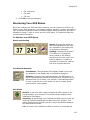
Data Zoom Level—The current data zoom level of the map
view; ranges between 1-0 (maximum zoom out) and 17-0
(maximum zoom in).
Zoom Tools—Buttons that quickly zoom out three levels, out
one level, or in one level. For more information, see Zooming In
and Out.
Compass Rose—A group of nine buttons on a globe. The outer
buttons have yellow arrows; click one of the arrow buttons to
pan the map in that direction. Click the middle button to center
the map on the previous map view. This button performs an
undo function for the last pan or zoom (up to 256 times).
Map Rotation Tool—The arrow in the graphic indicates True
North in relation to the rotated map. Use the Map Rotation Tool
to rotate the map in any direction. You can rotate the map by
clicking or dragging the square map graphic in the direction you
want or by selecting/typing the degree of map rotation from the
drop-down list.
Map Coordinates—Coordinates for the current map cursor
position display based on the units of measurement preferences
chosen in the Display tab of the Options dialog box.
Elevation and Interval—Display in the measurement chosen in
the Display tab of the Options dialog box. The data zoom level
affects interval display.
Scale Bar—Indicates the distance one scale bar unit equals in
the measurement chosen under in the Display tab of the Options
dialog box.
Overview Map
The overview map is a smaller map in the lower-right corner of the screen that offers
a wide-angle view of your current map view area. It is approximately three data
zoom-levels out from the current map view.
Tips
•
Click anywhere on the overview map and that point becomes the new map
center. This allows you to travel greater distances with each mouse click than
you can within the larger, current map view.
21
Topo USA 7.0 (SP 1) User Guide
•
Use the black view box in the overview map window to pan the map. Point
anywhere on the view box. When the pointer becomes a
box to the new location.
, drag the view
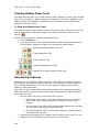
Toolbar
Use the toolbar at the top of the map screen to perform many functions in the
program without navigating through the tab area.
•
•
•
•
•
•
•
•
•
•
•
•
•
Create, save, and/or open Projects. These features can also be found in the
Map Files tab.
Print your current map screen. Find more printing functionality on the Print
tab or quick print with the current Print tab settings.
Share maps, route directions, or profiles with friends, family, or associates
with MapShare.
Launch the Eartha Community Atlas (ECA) wizard, where you can upload
information to the ECA website.
Set route start, finish, and stop points and calculate a route. This feature can
also be found on the Route tab.
Start or stop your GPS connection. This feature can also be found on the GPS
tab.
Exchange routes, waypoints, or tracks with a DeLorme Earthmate PN-Series
GPS or PDA.
Combine images and data with GPS information on the map with the
GeoTagger Wizard.
Grab and pan the map in any direction.
Profile a linear object on the map. You can also click the Profile tab, right-click
the linear object on the map, and select the Profile option).
Measure linear distance and area on the map based on the units chosen in the
Display tab of the Options dialog box.
Get information about a location on the map. You can also right-click a
location on the map and select the Info option.
Open the Options dialog box to set GPS, display, map feature, and keyboard
shortcut preferences.
Tip You can show or hide toolbar options and change the order of the toolbar
options.
22
Getting Started
Using the Help System
Help Overview
There are several ways to get more information about the program's features and
functionality.
On-screen Help
There are three ways to access Help within the program.
•
Pop-up Tutorials
When you perform some actions in the program, a pop-up Did you know . .
.? tutorial opens. These provide additional information for using that
particular function.
If you do not want to see that specific pop-up tutorial again, select the Do
Not Show Again check box before you close it.
If you do not want to see any pop-up tutorials , click the Help button
on the toolbar and then click Shut Off All Pop-Up Tutorials.
•
ToolTips
When you point to a tool for a few seconds, a short label (ToolTip) describing
the tool displays on your screen. ToolTips also display in windows and dialog
boxes when you point to a button, icon, or other feature.
•
Information Boxes
Several tabs contain information boxes. Information boxes provide
descriptions about the features and functions of the selected tab.
Help Menu
Click the Help button
click an item to select it.
on the toolbar to view the online Help options, and then
Tip To access a Help menu item using its underlined letter, click the Help button
and then press the underlined letter for the item on your keyboard. For example, to
access the Map Legend, click the Help button and then press the M key on your
keyboard.
Context-Sensitive Help
Click the context-sensitive Help button
are using.
to receive Help information for the tab you
Using the Help System
The Help system provides explanations of all of the features and functions of the
on the toolbar
application. To access the Help system, click the Help button
and then click Help Topics, or press the F1 key on your keyboard.
•
The Help system has three tabs.
Contents
23
Topo USA 7.0 (SP 1) User Guide
To view an outline of the Help system contents, click the Contents
tab.
•
To view the additional topics under a particular book, doubleclick the book.
•
To view a topic, click the page.
Index
Use the following steps to search the Help system index.
1. While in the Help system, click the Index tab.
2. Type a keyword in the entry field. The list automatically scrolls
to the closest matching entry.
3. Double-click the topic.
OR
Click the topic and then click Display.
OR
Click the topic and press the ENTER key on your keyboard.
Notes
•
If a topic has any secondary index references, a window
displays the secondary index options. Click the item of interest
to display the topic.
•
If you don't find what you're looking for in the index, click the
Search tab and try a search for your keyword.
Search
Use the following steps to search for particular words or phrases within
topics in the Help system.
1. While in the Help system, click the Search tab.
2. Type a keyword in the entry field and then click List Topics or
press the ENTER key on your keyboard. A list of topics
containing the keyword displays.
3. Double-click the topic under Select Topic to Display.
OR
Click the topic and then click Display.
OR
Click the topic and press the ENTER key on your keyboard.
24
•
The Help system keeps a history of viewed topics. Click the Back button to
browse backward through previous topics. Click the Forward button to
browse forward through the topics previously viewed.
•
Print any of the Help topics by selecting a topic (page with question mark) or
heading (book symbol) and then clicking the Print button. You can print only
the selected topic or a heading and all subtopics.
OR
Right-click the topic displaying in the right window to print only that topic.
Tip Before you click Print, expand any links in the topic that include
information you want to print within your topic.
•
While in the Help system, the pointer changes to a hand when it passes over
text or graphics that you can click for more information.
•
You can move, resize, and minimize the Help window.
Getting Started
•
To exit Help, click the close button
screen.
in the upper-right corner of the
Help Documentation Conventions
To help you easily locate and interpret information, this Help system is formatted.
There are also links that expand, jump to another location within the same topic, or
link you to other topics.
The table below defines each convention and its use.
The convention...
Is used for...
ALL CAPITALS
Acronyms, names of certain commands, and keys on the
keyboard.
Note Use of the plus sign (+) between key names
indicates key combinations that perform various actions.
For example, in the directions "Press CTRL+SHIFT+F3 on
your keyboard," you must press and hold the CTRL and
SHIFT keys while pressing F3.
Bold
Command buttons, tab names, and options when used in
procedures and exercise steps. Also used for information
that you type exactly into a particular field.
Headings and table headings are bold for emphasis.
Italic
Directory names and paths. Also used when referring to
titles of chapters, sections, and publications.
Blue underlined
text
Links. These links act differently depending on their
context. When it is:
•
Referenced with "for more information," the link goes to
another topic.
•
Embedded in text, such as in the example "Open the
file," the link goes to another topic, opens drop-down
text that expands within the same topic, or displays a
secondary window with a definition or graphic.
Red underlined
text
Opens expanding text that provides explanatory
information. The expanding text is italicized blue text.
Note
A note or notes that provide additional information.
Notes
Tip
A tip or tips that provide helpful hints.
Tips
25
Topo USA 7.0 (SP 1) User Guide
User Guide
The User Guide includes the entire Help system contents, modified for print, in a
portable document format (.pdf) file. When you access the guide, Adobe® Acrobat®
Reader launches. The User Guide contains a table of contents and you can print it as
a hard-copy reference.
on the toolbar and then click
To access the User Guide, click the Help button
User Guide in the menu to open the Technical Support website.
26
Tutorials
Tutorial: Creating Maps for an Earthmate PN-Series
GPS
How it Works
When you create a map package to send to your device, you can customize the
types of data and imagery you include, such as draw files (excluding waypoints and
tracks), imagery downloaded from NetLink, and Topo USA data.
Tip Topo USA 7.0 Data series is the same data that is on the detailed data DVDs
that came with your Earthmate PN-Series GPS. If you installed the detailed data for
the map you are creating, clear the Topo USA 7.0 Data Series check box on the
Handheld tab of the Options dialog box so you do not duplicate data in your map.
If you have routes, tracks, and waypoints in your Topo USA project, those items are
saved separately from the map package so you can manage them independently.
When you open the Exchange dialog to send the map package to your device, the
individual elements of your project appear in the left tree menu. When you send a
map package to your device, you must also send the routes, waypoints, tracks, and
maps separately.
You can send maps to an SD card or to the device's internal memory. You can send
routes, tracks, and waypoints to only the device's internal memory. For more
information about exchanging route, waypoints, and tracks, see the Exchanging Data
with an Earthmate PN-Series GPS tutorial.
To Create a Map Package
The tutorials for creating maps for an Earthmate GPS PN-20 or an Earthmate PN-40
follow.
Creating Maps for an Earthmate GPS PN-20
You can use Topo USA® to send custom (Custom map packages are created using
the Handheld Export tab and can be any size and cover any location in the U.S. The
data that is included in a custom map package is dependent on the data that is
available for the export area as well as your settings on the Handheld tab of the
Options dialog box. There is a size limit for map packages; if your custom map
package exceeds the limit, you will receive an error message.) or regional (Regional
map packages are pre-saved and contain general road and point data for multi-state
regions in the U.S. Regional map packages contain only Topo USA 7.0 data only.)
map packages to your Earthmate® GPS PN-20.
•
To create and send a custom map package, follow steps 1-5.
•
To send only a regional map package, go straight to step 5.
27
Topo USA 7.0 (SP 1) User Guide
Tip Topo USA 7.0 Data series is the same data that is on the detailed data DVDs
that came with your PN-Series GPS. If you installed the detailed data for the map
you are creating, clear the Topo USA 7.0 Data Series check box on the Handheld
tab of the Options dialog box so you do not duplicate data in your map.
Optimizing Performance
You can more quickly access maps on the device if they are saved to the GPS
device's internal memory; however, for large maps, the transfer process can be
slow. To speed up the transfer time, copy the map files to external memory using an
SD card with an SD card reader.
Using an SD card and reader
•
A Maps folder is automatically created on the card the first time you power on
an Earthmate PN series GPS with the SD card in the device or when you use
the Earthmate PN-Series GPS Exchange dialog to transfer data to an SD card
reader.
•
You can save regional maps or map packages to an SD card. Map packages
do not include routes, tracks, or waypoints.
•
Using an SD card allows you to:
•
Quickly transfer maps.
•
Improve performance of map packages with large file sizes, such as
those with imagery.
Creating a Map Package
Step 1 (Optional) — Download imagery for the area you want to
include in your map package
Your purchase of Topo USA 7.0 entitles you to free imagery and data downloads that
you can view in Topo USA as well as on your Earthmate GPS PN-20. For more
information, see the Downloading Imagery tutorial.
Step 2 — Modify your Handheld Export preferences
Before you use the Handheld Export tab to create your map package, ensure the
Handheld Export preferences are set to include the datasets and zoom levels you
want to include.
28
Tutorials
1. Click the Options button on the Handheld Export tab to open the Handheld
Options dialog box.
2. Make sure DeLorme Earthmate is selected under Export Map Format.
3. Select the check boxes next to the data types to include in your custom map
package. Only map data types connected to Topo USA are listed.
Optional. Modify the zoom levels for displaying the data on the device by
adjusting the gray sliders.
The gray blocks represent the zoom levels at which data displays in Topo
USA. You cannot modify these zoom levels.
The green bars represent zoom levels where the data performs best.
The red bars represent zoom levels where the data may have a poor
appearance and draw slowly on the device.
For more information, see Setting Your Handheld Export Preferences.
Step 3 — Find the location you want to include in your map
1. Click the Handheld Export tab.
2. Select the size of the grid for your map from the Grid Size list. See Grid Size
Comparisons for more information.
3. Type the location in the Search for and select a location text box.
The list below the text box shows the closest matches.
to see it on
4. In the list, click the location you want and then click
the map. The default export area for that location is defined with shaded
29
Topo USA 7.0 (SP 1) User Guide
grids.
Step 4 — Create the map package
1. Click
to select the default export area for your current map
center or click
to/from the export area.
to click the map and add/remove rectangles
2. Once you select the coverage area, type a name for your map package in the
Save your Map for Exchange text box.
3. Click Save.
A progress bar indicates the map package creation status.
30
Tutorials
Step 5 — Send the map package
1. Connect your Earthmate GPS PN-20 to your computer using the included USB
cord and power it on.
on the Handheld Export tab to open the Earthmate PN2. Click
Series GPS Exchange dialog box.
3. To save the map package in internal memory or on an SD card in the
device, select Earthmate GPS PN-20 from the drop-down list in the top
right corner of the dialog box.
OR
To save the map package on an SD card with an SD card reader, insert
your SD card into the reader and connect it to a USB port on your computer.
Select the removable disk option for your SD card reader from the drop-down
list in the top right corner of the dialog box.
This is the fastest method for transferring large map packages to the device.
4. To send a custom map package, click the plus sign next to Saved Map
Packages in the left pane of the dialog box. The available map packages
display.
OR
To send a regional map package, click the plus sign next to Regional Map
Packages. The available regions display.
5. Click the map package you want to send to the device.
6. To save the map package to internal memory, click the plus sign next to
Map Packages in the right pane of the dialog box and click Internal
Memory.
OR
To save the map package to an SD card within the device, click the plus
sign next to Map Packages in the right pane of the dialog box and click SD
Card.
OR
31
Topo USA 7.0 (SP 1) User Guide
To save the map package on an SD card with an SD card reader, go to
the next step.
7. Click Send.
The map package is sent to the device.
8. Click Done.
Notes
•
To insert an SD card into your Earthmate GPS PN-20, remove the
battery cover and batteries, and then gently press down on the
SD card latch within the battery compartment to open the slot.
Insert the SD card and press the slot down to close it. The device
automatically detects the maps on the SD card once it is powered
on.
•
See also, Creating a Map Package and Sending/Receiving Maps.
Creating Maps for an Earthmate GPS PN-40
You can use Topo USA® to send custom (Custom map packages are created using the
Handheld Export tab and can be any size and cover any location in the U.S. The data
that is included in a custom map package is dependent on the data that is available
for the export area as well as your settings on the Handheld tab of the Options dialog
box. There is a size limit for map packages; if your custom map package exceeds the
limit, you will receive an error message.) map packages to your Earthmate® PN-40
GPS.
Tip Topo USA 7.0 Data series is the same data that is on the detailed data DVDs
that came with your PN-Series GPS. If you installed the detailed data for the map
you are creating, clear the Topo USA 7.0 Data Series check box on the Handheld
tab of the Options dialog box so you do not duplicate data in your map.
Creating a Map Package
Step 1 (Optional) — Download imagery for the area you want to
include in your map package
Your purchase of Topo USA 7.0 entitles you to free imagery and data downloads that
you can view in Topo USA as well as on your Earthmate PN-40 GPS. For more
information, see the Downloading Imagery tutorial.
Step 2 — Modify your Handheld Export preferences
Before you use the Handheld Export tab to create your map package, ensure the
handheld export preferences are set to include the datasets and zoom levels you
want to include.
32
Tutorials
1. Click the Options button on the Handheld Export tab to open the Handheld
Options dialog box.
2. Make sure DeLorme Earthmate is selected under Export Map Format.
3. Select the check boxes next to the data types to include in your custom map
package. Only map data types connected to Topo USA are listed.
Optional. Modify the zoom levels for displaying the data on the device by
adjusting the gray sliders.
The gray blocks represent the zoom levels at which data displays in Topo
USA. You cannot modify these zoom levels.
The green bars represent zoom levels where the data performs best.
The red bars represent zoom levels where the data may have a poor
appearance and draw slowly on the device.
For more information, see Setting Your Handheld Export Preferences.
Step 3 — Find the location you want to include in your map
You can find your map location using the Find tab search functionality, the Search
feature in the Handheld Export tab, or by panning the map. For this tutorial, we are
using the Handheld Export tab.
1. Click the Handheld Export tab.
2. Select the size of the grid for your map from the Grid Size list. See Grid Size
Comparisons for more information.
3. Type the location in the Search for and select a location text box.
The list below the text box shows the closest matches.
to see it on
4. In the list, click the location you want and then click
the map. The default export area for that location is defined with shaded
33
Topo USA 7.0 (SP 1) User Guide
grids.
Step 4 — Create the map package
1. Click
to select the default export area for your current map
center or click
to/from the export area.
to click the map and add/remove rectangles
2. Once you select the coverage area, type a name for your map package in the
Save your Map for Exchange text box.
3. Click Save.
A progress bar indicates the map package creation status.
34
Tutorials
Step 5 — Send the map package
1. Connect your Earthmate PN-40 to your computer with the USB cable and
power it on.
The Connect to Computer screen appears.
2. On the device, highlight Map Transfer and press ENTER. Then, highlight
Transfer to SD Card to send the map to an SD card, or Transfer Internal
to send the map to internal memory and press ENTER.
When the Transfer Maps message appears, your Earthmate PN-40 is ready for
transfer. Set it aside.
3. In Topo USA, click the Exchange button
on the Handheld Export
on the toolbar.
tab or click the Exchange button
The Earthmate PN-Series Exchange dialog box opens.
4. If you are transferring to an SD card in the device, select the removable drive
(for example, Removable Disk E: Removable Disk) from the drop-down list in
the upper-right corner of the dialog box.
OR
If you are transferring to internal memory, select the internal memory drive
(for example, EM_USERMAPS E: Removable Disk) from the drop-down list.
The internal memory is treated as if it is an external drive.
5. In the left pane of the dialog box, click the plus sign next to Saved Map
Packages, and then click the map package you want to send to your device.
OR
To select all map packages, just click Saved Map Packages.
6. In the right pane of the dialog box, under Map Packages, click Internal
Memory or SD Card.
7. Click Send.
A progress bar indicates the copy status.
35
Topo USA 7.0 (SP 1) User Guide
8. Click Done.
9. On your Earthmate PN-40, press ENTER to return to GPS use.
Notes
•
To insert an SD card into your Earthmate PN-40, remove the battery cover
and batteries, and then gently press down on the SD card latch within the
battery compartment to open the slot. Insert the SD card and press the
slot down to close it. The device automatically detects the maps on the SD
card once it is powered on.
•
You can transfer maps using the Data Transfer option on the device's
Connect to Computer screen and then selecting the device in the
Earthmate PN-Series Exchange dialog box; however, transfer will be slow
as the device is not being used as an external drive.
•
If you bypassed the Connect to Computer screen on the device, go to the
Device Setup>Connect to Computer menu and select the option you
want from the USB Setting drop-down list.
•
You can also use an SD card and an SD card reader instead of an SD card
in the device. You do not have to connect your device to your computer.
Just insert the SD card/reader into your computer and in the Exchange
dialog choose that drive to transfer your map to.
•
See also, Creating a Map Package and Sending/Receiving Maps.
Tutorial: Exchanging Data with an Earthmate PNSeries GPS
Use the Earthmate® PN-Series GPS Exchange dialog box to send and receive
waypoints, tracks, routes to and from the Earthmate PN-Series GPS. When planning
a trip, use Topo USA® to create a set of waypoints, a track, and a route that identify
the locations you are interested in visiting.
Tip To manage waypoints and tracks for a particular trip, create and name a new
layer for the trip's waypoints and tracks. It is also helpful to create new projects for
each of your trips.
Step 1 — Create your trip information
Use Topo USA 7.0 to create your trip information. For more information, see the
following Help topics:
•
Creating a Route
•
Adding a Waypoint, Symbol, MapNote, Text Label, or Image to the Map
•
Drawing a Track on the Map
•
Creating a Map Package and the detailed Creating Maps for an Earthmate PNSeries GPS tutorial.
•
See also the help topics for your specific device under Using Handheld
Devices.
Step 2 — Connect Your Device to Your Computer
•
36
If you have an Earthmate PN-20, connect your device to your computer
with the USB cable and power it on.
Tutorials
•
If you have an Earthmate PN-40, connect your device to your computer
with the USB cable and power it on. On the Connect to Computer screen,
highlight Data Exchange and press ENTER.
Step 3 — Open the Earthmate PN-Series GPS Exchange dialog box
Click the Exchange button
on the toolbar to open the Earthmate PN-Series
GPS Exchange dialog box. Your device displays in the top right corner of the dialog
box.
Step 4 - Send information from Topo USA to the device
1. Select the waypoints, tracks, and routes that you want to move from the
computer to your device.
•
To send waypoints to the device
1. On the left side of the dialog box, click the plus sign next to
Waypoint Layers.
The waypoint files in the current project display in the tree
view.
2. Click the plus sign next to each waypoint layer to view its
contents.
3. Highlight a specific waypoint to send that waypoint, a waypoint
layer to send all waypoints in that layer, or Waypoint Layers
to send all waypoint layers.
4. Click Send.
•
To send tracks to the device
1. On the left side of the dialog box, click the plus sign next to
Track Layers.
The track files in the current project display in the tree view.
2. Click the plus sign next to each track layer to view its contents.
3. Highlight a specific track to send that track, a track layer to
send all tracks in the track layer, or Track Layers to send all
track layers.
4. Click Send.
•
To send routes to the device
1. On the left side of the dialog box, click the plus sign next to
Routes.
The routes in the current project display in the tree view.
2. Highlight a specific route to send that route or Routes to send
all routes.
3. Click Send.
37
Topo USA 7.0 (SP 1) User Guide
2. Click Done to close the dialog box.
Step 5 — Collect data with your device
Go on your trip and use your device to collect new data. For this trip, try adding
some waypoints, record a track, and create a route. See your Earthmate PN-Series
GPS User Manual for more information.
Step 6 — Send information from the device back to Topo USA
Once you return from your trip, use the Earthmate PN-Series GPS Exchange dialog
box to receive the new waypoints, tracks, and routes that you created.
1. Connect your computer to your device as in Step 2.
2. Click the Exchange button
the drop-down list.
on the toolbar and select your device from
3. Select the waypoints, tracks, and routes you want to receive into Topo USA.
•
To receive waypoints from the device
1. On the right side of the dialog box, click the plus sign next to
Waypoints.
The waypoint files on the device display in the tree view.
2. Highlight a specific waypoint to send that waypoint or
Waypoints to send all waypoint layers.
To send a waypoint to an existing waypoint layer in Topo USA,
highlight the layer that you want to receive the waypoint on the
left side of the dialog box.
3. Click Receive.
•
To receive tracks from the device
1. On the right side of the dialog box, click the plus sign next to
Tracks.
The track files on the device display in the tree view.
2. Highlight a specific track to send that track or Tracks to send
all tracks.
3. Click Receive.
•
To receive routes from the device
1. On the right side of the dialog box, click the plus sign next to
Routes.
The routes on the device display in the tree view.
2. Highlight a specific route to send that route or Routes to send
all routes.
3. Click Receive.
4. Click Done to close the Earthmate PN-Series GPS Exchange dialog box.
Tutorial: Downloading Imagery
Your purchase of Topo USA® includes a Data Download Dollars certificate for $40 of
imagery downloads! You can download aerial, satellite, USGS Quad data, NOAA
nautical charts, and more. You must be a registered user to receive your imagery. If
you did not register during the product installation, you can register using the
NetLink tab.
38
Tutorials
Once you have used your certificate downloads, the most cost-effective way to
purchase data is through the Map Library subscription plan.
Note The NetLink tab is an online connection within the application. To see the most
recent NetLink Help file, click the blue NetLink Help button
within NetLink.
This tutorial explains how to download color imagery.
Step 1 — Find the area you want to download
Center the map on the area for which you want to download imagery and zoom the
map in to data zoom level 11-0 or greater.
Step 2 — Activate your certificate
1. Click the NetLink tab and then click the Map Library subtab.
2. The first time you open the Map Library subtab, The Activation screen
displays. Type your certificate key in the Validation Key box to activate it
and then click Enter.
Note If you bypass this screen, you can enter your certificate key later.
Step 3 - Select the coverage area
1. From the Delivery Method drop-down list, select Download.
2. Click the Select button
and then click inside the grids that cover
the area you want to download.
The selected grids are highlighted. The blue info box updates to show
information about the download.
Step 4 - Add the imagery to your download
1. Click the Add to List button
to your selection list.
to name and add the selected areas
39
Topo USA 7.0 (SP 1) User Guide
2. Type the name of your map in the Name Your Selection box and then click
OK.
Step 5 - Complete your order
Click Checkout to complete the ordering process.
Note If the order exceeds $40, you must pay the difference or purchase a
subscription. If the order is less than $40, your certificate number is credited with
the difference.
40
Tutorials
Step 6 - View license agreement and submit order
The first time you download imagery or data, a license agreement displays. Read the
agreement and click I Agree.
Step 7 - Download your imagery or data
Once you have completed the checkout process, the Downloads subtab opens and
displays your order in progress.
When the download is available:
•
You are notified on the Downloads tab. Follow the download instructions.
•
If you are not on the Downloads tab, a notification dialog box opens when
your download is ready. Follow the download instructions.
•
You are also sent an e-mail to the e-mail address you provided when you
registered so you can be notified when Topo USA is closed. Open Topo USA,
and, when the notification dialog box opens, follow the download instructions.
Step 8 - View your imagery
Use the map resize tool to expose the left map view. Then, use the drop-down list in
the upper-left corner of the left map to switch the imagery type to the one you
purchased.
41
Topo USA 7.0 (SP 1) User Guide
Note You can view imagery only in the left window. To view roads and other data
over the imagery, click the Hybrid Map button at the top of the left window.
Tutorial: Creating a Route
There are several different methods for creating a route on the Route tab. You can
designate a start, stop, via, and finish for your route. You can also designate:
•
Your method of transportation — car, bicycle, or on foot
•
The route calculation — road quickest, road shortest, direct, or trail
•
Special routing preferences, such as establishing speeds for particular road
types, preferred roads, roads to avoid, and more.
You can also create a route on a map using the right-click function or with the route
buttons on the toolbar. These two features let you create routes while using any tab
42
Tutorials
in the program. For more information on using these alternative methods, see
Creating a Route.
For more information about adding stops and vias, see Adding and Inserting Stops
and Vias.
This tutorial provides steps for creating a hiking trail route with the Route tab.
Step 1 — Set the route start
Click the Route tab and type the start location for your route in the Start text box.
Step 2 — Add a stop
Assign your first stop by typing it in the Stop text box. Since you are adding your
stops in the order you want to reach them along your route, make sure the Add
option is selected and then click Add to assign the stop.
Note The Stop text box clears itself after you click the Add button. This allows you
to use the text box to add more stops.
Step 3 — Add a second stop
Assign your second stop using the same procedure outlined in step 2.
Step 4 — Add the route finish
Since you want to finish your route where you started, use the same finish location
that you used for your start point in step 1.
Step 5 — Select your activity type
To ensure the route is calculated for your activity, select the Walking/Jogging
button and then select Trail as the route calculation method.
43
Topo USA 7.0 (SP 1) User Guide
Step 6 — Calculate the route
Click Calculate to calculate the trail route. The route displays on the map.
Tip Select the Auto check box next to the Calculate button to automatically
calculate the route after you add each point.
Tutorial: Converting Tracks into Trails
You can send and receive objects, such as handheld maps, routes, waypoints, tracks,
and GPS log files to and from an Earthmate PN-Series GPS or another GPS or PDA
device.
This tutorial provides instructions for receiving a track from an Earthmate PN-Series
GPS to Topo USA® and then converting it to a trail so you can use it when
calculating trail routes. If you are not using an Earthmate PN-Series GPS, click Use
Other Device in Step 1 to open the Exchange Wizard and follow the instructions
for receiving a track from a GPS device. Then go to Step 3.
Step 1 — Connect Your Device to Your Computer
44
•
If you have an Earthmate PN-20, connect your device to your computer
with the USB cable and power it on.
•
If you have an Earthmate PN-40, connect your device to your computer
with the USB cable and power it on. On the Connect to Computer screen,
highlight Data Exchange and press ENTER.
Tutorials
Step 2 — Open the Exchange dialog
Click the Exchange button
GPS Exchange dialog box.
on the toolbar to open the Earthmate PN-Series
Step 3 — Select the track to send to Topo USA
1. On the right side of the dialog box, click the plus sign next to Tracks.
The track files on the device display in the tree view.
2. Highlight a specific track to send that track or to send all tracks, click Tracks.
3. Click Receive.
4. Once the file is transferred, click Done.
45
Topo USA 7.0 (SP 1) User Guide
Step 4 — Open the file in Topo USA
The track is saved in a Draw file. To view the track, click the File button in the Draw
tab and double-click the track name you want to convert.
Step 5 — Convert the track to a trail
To convert the track to a trail, select the track in the Draw File list, click the Copy To
button, and then click Trail. The track is converted to a trail.
46
Tutorials
Step 6 — Join broken trail lines
The large red circle indicates a break in the user trail. The small red circle indicates a
break between the user trail and the existing trail.
To ensure routability on the trail, you must join the trail lines and then snap them to
existing trails/roads.
1. Click Done to return to the main Draw tab area.
in the Draw tab, press the SHIFT key on your
2. Click the Select tool
keyboard, and then click both of the trail segments. Boxes display around
each segment.
3. Right-click one of the segments, point to Manage Draw, and then click Join
Lines.
47
Topo USA 7.0 (SP 1) User Guide
Step 7 — Snap the new trail to an existing trail
To snap the new trail to an existing road/trail:
1. Click the Select tool and then click the trail on the map.
2. Click the pink end point of your trail that is closest to the existing road/trail (it
will display as a red circle) and drag it to the existing road/trail. A yellow
diamond defines the snap point.
3. Release the point when the snap point displays.
The new trail is now snapped to the existing road/trail and can be used when
creating a route.
Tutorial: Using MapShare
MapShare lets you create static maps with or without route directions or profiles to
send to your friends, family, and associates.
Step 1 — Open the MapShare Wizard
Click the MapShare button
on the toolbar. The MapShare Wizard opens.
Step 2 — Select the type of information you want to share
Select Share the Current Map View (a static map), Share a Route Map and
Directions, or Share the Current Profile and then click Next.
For this tutorial, we will share a route map and directions.
48
Tutorials
Step 3 — Select the route to share
Select the route file you want to share from the Available Routes drop-down list
and then click Next.
49
Topo USA 7.0 (SP 1) User Guide
Step 4 — Add a title or notes to the route map
To add a title or notes to your route map, type the appropriate information in the
text boxes and click Next.
50
Tutorials
Step 5 —Add notes to the directions
Then, if you would like to add notes to display with your directions, type them in the
Notes text box and click Next.
51
Topo USA 7.0 (SP 1) User Guide
Step 6 — View upload confirmation
A message telling you that your map has been uploaded successfully to the
MapShare site displays. Click Next.
52
Tutorials
Step 7 — Preview or e-mail the route
Click E-mail the MapShare Link for Your Route Map and Directions to e-mail a
link of your route map and directions. This option is available only if an e-mail
program is detected. If an e-mail program is not detected, copy and paste the link
provided into your online e-mail program.
AND/OR
Click Preview Your Route Map and Directions to preview your route map and
directions as they appear on the MapShare site.
Note Print your route map and directions from the MapShare site by clicking Print
in the upper-right corner of the page.
53
Topo USA 7.0 (SP 1) User Guide
Step 8 — Exit the MapShare Wizard
Click Close to exit the MapShare Wizard.
Tutorial: Flying in 3-D
The 3-D feature in Topo USA® lets you “fly” over the 3-D map, letting you simulate
an upcoming hike or road trip. This is great for when you want to get a feel for the
elevation differences and surroundings along the way.
Step 1 — Create a route
Create a trail route using right-click functionality, the toolbar, or the Route tab. For
more information on creating a route, see the Creating a Route tutorial or Creating a
Route Help topic.
54
Tutorials
Step 2 — Save the route as a GPS log file
Right-click the calculated route and click Save as GPS Log File.
55
Topo USA 7.0 (SP 1) User Guide
Step 3 — Open the GPS log file
Open the newly created GPS Log file using the GPS Log subtab in the GPS tab.
Step 4 — Play the GPS log file
Click the Play button to play back the GPS Log file.
Step 5 — Adjust 3-D settings
Use the tools in the 3-D tab to adjust the rotation, pitch, and more.
Step 6 — View the map in 3-D
Drag the resize tool to the right (or double-click the bar above the right arrow) to
view the map in full, 3-D mode. Make sure 3-D is selected in the select map view
drop-down list.
56
Tutorials
Step 7 — View the GPS log file playback in 3-D
Use the tab area resize tool to minimize the tab area and view the GPS log file
playback with a hands-free, full 3-D experience.
57
Map Legend
The features that display on the map may display differently depending on which
map colors you chose in the Display tab of the Options dialog box. The tables below
show the symbolization of each feature, by map color.
Notes
•
Not all features are available at all zoom levels.
•
Not all features are available in all datasets.
•
High-contrast Color features display the same as Street Color features (except
for land, which displays as black).
Routable Trail Features
Topo
Colors
Street
Colors
Description
Major Trail
Important Some trails may cross private property. Contact
the applicable trail department to ensure you have the
appropriate permissions before following a major trail. For
contact information, see Recreational Contacts.
4-wheel Drive Trail
Trail/Walkway/Foot Trail
Routable Road Features
Topo
Colors
Street
Colors
Description
Ferry Passenger
Ferry Vehicle
Interstate Highway (can also include this symbol:
)
Limited Access Road
Local Road
Major Connector, Forest Road
Minor Connector
Non Limited Access Interstate
Primary State Route
State Route (can also include this symbol:
)
Toll Road
U.S./National Route (can also include this symbol:
)
Unclassified Road
Unimproved Road
59
Topo USA 7.0 (SP 1) User Guide
Land Cover
Topo
Colors
Street
Colors
Description
Bare Rock or Sand
Bureau of Land Management Land
Bureau of Mine Reclamation Land
Forest, evergreen
Forest, mixed
Ice or Snowfield
Indian Reservation (at data zoom level 11)
Indian Reservation (at data zoom level 2 thru 10-7)
Intermittent Water
Land
Military Area (at data zoom level 11)
Military Area (at data zoom level 2 thru 10-7)
Mine or Quarry
Parks
River/Stream
Transitional Area, Lava, Salt Flats, or Mixed Barren
Water
Wetlands
60
Map Legend
Point Features
Topo
Colors
Street
Colors
Description
Amusements
Airport (private)
Airport (commercial public)
Airport (general aviation public)
Business (Amusement, Recreation, Specialty or Department
Store)
Camping (at data zoom level 14)
Camping (at data zoom level 11 thru 13)
Cemetery
Educational Facility
Exit, with services (at data zoom levels 10 thru 11-7)
Exit, without services (at data zoom levels 10 thru 11-7)
Exit, food (at data zoom levels 12 thru 17)
Exit, gas (at data zoom levels 12 thru 17)
Exit, lodging (at data zoom levels 12 thru 17)
Exit, other (at data zoom levels 12 thru 17)
Fast Food
Gas
Hospital
Lodging
Metropolitan City
National Capital (data zoom level 7 thru 10)
National Capital (data zoom levels 2 thru 6)
Point of Interest (smaller black square)
Population Center
Public Service
Religious (buildings)
Rest Area with Facilities (at data zoom levels 10 thru 11)
Rest Area with Facilities (at data zoom level 12)
Rest Area without Facilities (at data zoom levels 10 thru 11)
61
Topo USA 7.0 (SP 1) User Guide
Rest Area without Facilities (at data zoom level 12)
Restaurants (general)
Restaurants (specialty)
Small City
State Capital
Unique Natural Feature (at data zoom level 8)
Line Features
Topo
Colors
Street
Colors
Description
County Boundary
Dam
Game Management District
International Boundary
Park Boundary
Pipeline
Power Line
Railroad (Abandoned)
Railroad
Runway
State Boundary
DeLorme Atlas and Gazetteer Symbols
Symbol
Description
Developed Boat Ramp (at data zoom levels 11 and 12)
Developed Boat Ramp (at data zoom level 13)
Freshwater Fishing (at data zoom levels 11 and 12)
Freshwater Fishing (at data zoom level 13)
Hunting (at data zoom levels 11 and 12)
Hunting (at data zoom level 13)
Saltwater Fishing (at data zoom levels 11 and 12)
Saltwater Fishing (at data zoom level 13)
Undeveloped Boat Ramp (at data zoom levels 11 and 12)
Undeveloped Boat Ramp (at data zoom level 13)
62
Using the Toolbar
Showing/Hiding Toolbar Options
You can customize the toolbar to show the options you use most. You can also
activate toolbar options that are not turned on by default.
To modify the toolbar.
1. Right-click the toolbar.
Toolbar options with a check mark next to them are displayed on the toolbar.
2. Click the item to show or hide it on the toolbar.
Reordering the Toolbar Options
To reposition the toolbar segments horizontally or vertically, just drag the dotted
vertical bar
that separates each segment to the new location (left, right, up, or
down). You cannot move a toolbar segment above the top line on the toolbar.
To Create New Projects
To create a new project, click the New button
on the toolbar. If you made
changes to the open project, the Save Changes dialog box opens to ask you if you
want to save your changes.
For more information, see Creating and Deleting Projects.
To Save a Project
To save the project that is currently open:
on the toolbar.
1. Click the Save button
The Save File dialog box opens.
2. Browse to the location where you want to save the project.
Type a new name in the File Name text box if you want to rename the
project.
3. Click Save.
To Print
To print a map using the current settings in the Print tab, click the Print button
on the toolbar.
For more information, see Printing a Map.
To Print the Map Screen
To print the current view as it displays on the screen (the control panel, tab area,
map view, and so on), click the Print Screen button
on the toolbar.
63
Topo USA 7.0 (SP 1) User Guide
To Share Maps
To share your current map view, a route map and directions, or a profile, click the
MapShare button
on the toolbar to open the MapShare Wizard.
MapShare lets you share maps — even 3-D maps, routes, and profiles.
For information on e-mailing maps, routes, and profiles with the MapShare Wizard,
click the Help button in the MapShare Wizard.
To Share Online With Eartha Community Atlas
To launch the Eartha Community Atlas (ECA) wizard, click the ECA button
the toolbar. You can also access the Eartha Community Atlas website.
on
See Using Eartha Community Atlas for more information.
To Create a Route
To set route points using the toolbar:
1. Type the location where you want to start your route in the Start text box
(next to the green Start button).
OR
and then click the location on the map
Click the green Start button
where you want to start your route.
OR
Select an address book entry, a previous location, or your current GPS
position from the Start drop-down list.
2. Type the location where you want to end your route in the Finish text box
(next to the red Finish button).
OR
and then click the location on the map
Click the red Finish button
where you want to end your route.
OR
Select an address book entry or your current GPS position from the Finish
drop-down list.
3. Optional. If you want to add a stop to your route, click the Stop button
and then click the location on the map where you want to add or insert the
stop. Repeat this step for each stop or via you want to add to your route.
Note If the Add option is selected in the Route tab, stops are added in the
order they are added to the route. If the Insert option is selected in the Route
tab, stops are added in the order they are approached in the route. For more
information, see Adding and Inserting Stops and Vias.
4. Click the Calculate button
.
Important If you have only the left map window open, the route Start, Finish, and
Stop buttons on the toolbar and on the Route tab are grayed out. To activate the
options, use the map resize tool to expose the right map window.
64
Using the Toolbar
Note To use the current GPS location in a route, you must connect your device to
your computer and click the Start GPS button on the toolbar or on the GPS tab.
Tip Once a route is calculated, you can use the subtabs in the Route tab to view
route directions, edit a route, and more. Click the Directions subtab to view the
route directions, the Advanced subtab to display the advanced routing options, or
click Back on Track to add your current GPS position as a stop to the current route.
To Start/Stop Your GPS Connection
To start or stop your GPS connection, click the GPS button
on the toolbar. If you
are starting a connection, the GPS tab area opens so you can monitor your GPS
status.
Note The GPS button on the toolbar is a toggle button that lets you start your GPS
connection if the device is not active, or stop the connection if it is active.
To Exchange Files with a GPS or PDA
Use the Exchange button
on the toolbar (also on the GPS and Handheld
Export tabs) to exchange objects such as maps, waypoints, tracks, and routes with a
handheld device.
•
If you have enabled an Earthmate PN-Series GPS on your computer, click the
Exchange button to open the Earthmate PN-Series GPS Exchange dialog. You
can switch to another device from this dialog.
•
If you have another GPS device, a Palm® OS device, or a Pocket PC device,
click the Exchange button to open the Earthmate PN-Series GPS Exchange
dialog and then click Use Other Device.
For more information on exchanging objects, see Help topics listed under Using
Handheld Devices.
To Add Images and Data to a GPS Location
To open the GeoTagger Wizard, where you can combine images and data with GPS
information on the map, click the GeoTagger button
information, see Getting Started with GeoTagger.
on the toolbar. For more
To Grab and Pan the Map
To drag and pan the 2-D or 3-D map in any direction, click the Grab and Pan button
on the toolbar.
To Create a Profile
To create a profile:
1. Center your 2-D map on the area with the linear object you want to profile.
OR
Center the route you want to profile on the map.
65
Topo USA 7.0 (SP 1) User Guide
2. Click the Profile button
on the toolbar.
3. Move your pointer over the map. The pointer changes from
when it passes over an object that you can profile.
to
4. Select a linear object or route on the map to generate its profile.
When the object is selected, it is highlighted and the Profile graph displays in
the Profile tab area.
Note Move your pointer along the elevation profile in the Profile graph. The
intersection of the vertical and horizontal blue lines travels along the top of
the terrain profile. These lines indicate the height and distance of the
particular location. A small crosshair follows along the corresponding object
on the map.
You can also right-click a linear object or route on the map and click Profile in the
shortcut menu. For more information about profiles, see the Help topics under
Profiling Linear Objects.
To Measure Distance
Use the following steps to measure linear distances and perimeter/area on the map.
For more information, see Measuring Distance and Area.
1. Click the Measure tool
on the toolbar.
2. Click point-by-point to draw a measurement line on the map. A text box
displays next to your pointer indicating the total distance of the measurement
taken.
Note When you pass over a point in a road, measurement line, or
measurement area to which you can snap, a yellow circle defines the snap
point. Click to snap the point of the measure line to the road or measurement
object's point coordinate. Press and hold the ALT key on your keyboard to
disable snapping.
3. To end a measurement line, double-click the last point of the measurement
line. The measure line displays as a two-pixel wide yellow line and the total
length of the line displays in a label at each endpoint of the line.
4. To end a measure area, hover over the starting point until the yellow snap
circle displays and then double-click the last point to the starting point. The
perimeter measurements display.
To Get Information About a Location
Use the Information button
on the toolbar to click a point, symbol, feature,
measurement line, track, or area on the map to identify it and view detailed
information about it.
Use the following steps to get information about a particular map feature.
1. Click the Information button.
2. Click the map feature you want information for, such as a road, town,
measurement line, waypoint, track, draw symbol, or point of interest.
The Info tab opens and displays a list of information categories.
Note Descriptive information may include a name or feature type,
66
Using the Toolbar
length/area, ZIP Code, town name, county name, state, coordinates, and
Standard Industrial Classification categories.
3. Click the plus sign next to each of the information categories to expand the
category to view more detailed information.
OR
Right-click in the information box and click Expand All to expand all of the
information categories. Right-click in the information box again and click
Collapse All to minimize all of the information categories.
4. Optional. Repeat steps 1–3 to get information about another location.
5. Optional. Right-click in the information box and click Print to print your map
feature information.
Notes
•
You can also get information about a location using right-click functionality. Just
right-click the location and click Info.
•
The status bar (located above the tab area) displays draw object type, draw file
information, point of interest name (if applicable), street name/address,
highway, city, state, and ZIP Code information for the map location that your
cursor is positioned on.
•
Some map features (such as campgrounds, national scenic/historic trail
information centers, and state parks) display with a blue outline at data zoom
levels 15-0 through 17-0. The blue outline indicates that the feature has a
hyperlink to its website. To open the hyperlink, right-click the feature and then
click Open Hyperlink OR click the URL in the Info tab.
To Open the Options Dialog Box
To open the Options dialog box, click the Options button
on the toolbar.
Use the Options dialog box to set GPS, display, map feature, handheld, 3-D, and
keyboard shortcut preferences.
An Options button is also available on the 3-D, Handheld Export, and GPS tabs.
67
Customizing the Map and Tab Display
Display Options Overview
See the following Help topics to learn more about the Display options in the Options
dialog box.
•
Changing the Map Colors
•
Changing the Map Magnification Level
•
Changing How POIs Display on the Map
•
Setting Units of Measure Preferences
Resizing the Map and Tab Areas
You can horizontally and vertically resize the primary (right) map, secondary (left)
map, tab area, and overview map with the map and tab area resize tools.
Notes
•
The tab and overview map window size does not change when you choose
another tab.
•
Some tab areas that provide search results automatically resize depending on
the number of results.
To Resize the Map and Tab Area Using the Drag Method
Use the drag method to horizontally or vertically resize these areas.
1. Point to the frame area between the tab and overview map windows. The
pointer becomes a
.
OR
Point to the horizontal edge of the tab/main map window. The pointer
becomes a
.
2. Drag to resize.
3. To cancel the resize while dragging, press the ESC key on your keyboard. The
size just prior to this resize is restored.
To Resize the Map Area Using the Resize Tools
The map resize tool runs perpendicular to the tab area. If the secondary and primary
maps are both displaying, the resize tool is the bar that separates them. When the
bar is moved all the way to the left of the map, only the primary map displays. When
the bar is moved all the way to the right of the map, only the secondary map
displays.
There are several methods you can use to resize the map area:
•
Drag the bar left to expose the area of the primary map you want to see.
•
Drag the bar right to expose the area of the secondary map you want to see.
•
Click the right arrow on the resize tool once to move the secondary map 1/4
of the screen width. You can repeat this step until the primary map is no
longer visible.
69
Topo USA 7.0 (SP 1) User Guide
•
Click the left arrow on the resize tool once to move the primary map 1/4 of
the screen width. You can repeat this step until the secondary map is no
longer visible.
•
Double-click the bar above the right arrow to show only the secondary map.
•
Double-click the bar below the left arrow to show only the primary map.
•
Double-click the bar between the right and left arrows to display an equal
percentage of both the secondary and primary maps.
To Resize the Tab and Map Area Using the Resize Tools
There are two tab area resize tools. The horizontal resize tool is located above the
tab area and lets you adjust the height of the tab area. The vertical resize tool is
located between the tab area and the overview map lets you resize the width of the
tab area.
Using the Horizontal Resize Tool
•
Drag the horizontal bar up/down to expose the tab area you want to see.
•
Click the up arrow on the horizontal resize tool once to incrementally increase
the tab height. You can repeat this step until the top of the tab area is flush
with the bottom of the compass rose in the control panel.
•
Click the down arrow on the horizontal resize tool once to incrementally
decrease the tab height. You can repeat this step until only the tab names
display.
•
Double-click the bar to the right of the up arrow to expand the tab height to
its maximum percentage (if the tab height is at the default mode or higher).
Note If the tab area is below the default mode, double-click the bar to return
the tab height to its default percentage.
•
Double-click the bar to the left of the down arrow to decrease the tab height
to its minimum percentage (if the tab height is at the default mode).
Note If the tab area is above the default mode, double-click the bar to return
the tab height to its default percentage.
•
Double-click the bar between the up and down arrows to return the tab height
to its default view.
Using the Vertical Resize Tool
70
•
Drag the vertical bar left to expose the area of the overview map you want to
see.
•
Drag the vertical bar right to expose the tab area you want to see.
•
Click the right arrow on the vertical resize tool once to incrementally increase
the tab width. You can repeat this stop until the overview map is no longer
exposed.
•
Click the left arrow on the vertical resize tool once to incrementally increase
the width of the overview map. You can repeat this step until the tab area is
no longer exposed.
•
Double-click the bar above the right arrow to show only the tab area.
•
Double-click the bar below the left arrow to show only the overview map.
•
Double-click the bar between the right and left arrows to return the tab and
overview maps to their default views.
Customizing the Map and Tab Display
Viewing Two Maps Simultaneously
Split-window functionality lets you view two maps at the same time.
You can access the left map using the map resize tool that runs perpendicular to the
tab area. If the left and right maps are both displaying, the resize tool will be the bar
that separates them. When the bar is moved all the way to the left of the map, only
the right map will display. When the bar is moved all the way to the right of the
map, only the left map will display. For more information on using the map resize
tool, see Resizing the Map and Tab Areas.
Accessing Data Collections
When the left map window is activated, a bar displays on the top of the left map (see
graphic below). This bar displays two drop-down lists: one for swapping data and
one for changing the map from 2-D to 3-D and vice versa. You can also show hybrid
maps and use zoom tools that work specifically with the left map window. All of the
Topo USA-compatible data collections that you saved to your hard disk drive are
available from the data drop-down list.
Note For more information about saving data to your hard disk drive, see Saving
Topo USA Data to Your Hard Disk Drive.
Note The graphic above displays color aerial imagery, available separately from
DeLorme.
Additional Facts About Split-Window Functionality
The maps interact as follows:
•
If you are viewing both the right and left maps at different data zoom levels,
a box (or lines, depending on the current data zoom level) displays on the
map that is zoomed out the furthest. The box/lines indicate the area that is in
view on the opposite map.
•
If you are viewing the right and left maps at the same data zoom level but
they are not equally represented on the screen (50/50), a box (or lines)
displays on the map that is covering the larger amount of screen area. The
box/lines indicate the area that is in view on the opposite map.
•
Both windows are centered on the same coordinate position. Panning or
rotating in one map causes the same action on both maps.
•
The left map window has its own zoom level controls. You can change the
zoom level of the left map without affecting the zoom level in the right map
window. However, after you adjust the zoom level in the left map window, the
zoom tools on the Control Panel incrementally adjust the map. For example, if
the left map is at zoom level 6-0 and the right map at zoom level 8-0, and
you click the Zoom Out 1 tool, the left map displays at zoom level 5-0 and the
right map at 7-0.
•
The overview map in the tab area is always associated with the right map
window.
•
Other tab functionality may be affected by use of the split-screen function, as
follows:
Draw—The line and polygon draw tools work in either map window.
The Select tool
highlights the same draw object on both maps
71
Topo USA 7.0 (SP 1) User Guide
and you can then manipulate both objects at the same time. Draw files
are created for both windows in the same project.
Route—You can create routes only in the right window; routes display
in both windows.
GPS—You can log with GPS in the right map window; log playback
displays in both windows.
3-D—The 3-D map always displays in the left map window.
Showing Hybrid Maps
Raster data, such as aerial and satellite data, is image-based and does not provide
typical map information, such as street names, route numbers, and so on. The
Hybrid Map feature in the left map window lets you overlay this type of map
information onto raster data.
To Show Roads and Text Labels on Imagery
Use the following steps to show roads, road names and numbers, names of bodies of
water and more on imagery in the left map window.
1. Ensure the left map window is displaying and your raster data, such as
Satellite Imagery (Sat 10) or Aerial Imagery (DOQQ),is displayed.
2. At the top of the left map window, select the raster dataset from the data
drop-down list.
3. Click Hybrid Map. All roads, contours, points, text labels, and so on display
identically to the data that is displayed in the right map window.
Note The Hybrid Map button is unavailable when you select a vector dataset
type.
Note You cannot create a route in the left map window. Once you create a route in
the right map window, the route line displays in the left map window.
Changing the Map Colors
When you use a laptop computer while traveling, it can be difficult to see the map
display on your screen. This can be especially true at nighttime or on a bright sunny
day. Changing your default map colors to high-contrast map colors can make your
map display easier to see.
To Change the Map Colors
Use the following steps to change the map display.
1. Click the Options button
on the toolbar.
2. Click the Display tab.
3. From the Map Colors drop-down list, select High-Contrast Colors to make
the map display darker for improved in-vehicle visibility, Street Colors to
emphasize streets and highways on the map, or Topo Colors to emphasize
contours, parks and public lands, land cover, and so on.
4. Click OK to accept the change and exit the Options dialog box.
OR
Click Apply to accept the change and keep working in the Options dialog box.
72
Customizing the Map and Tab Display
Changing the Map Magnification Level
If you want to change the size of the map image, but not change the degree of
geographic detail on the map, use the magnification settings in the Options dialog
box.
To Change the Map Magnification
Use the following steps to change the map magnification.
1. Click the Options button
on the toolbar.
2. Click the Display tab.
3. Select a magnification percentage (50%, 75%, 100%, 125%, 150%,
175%, or 200%) from the Magnification drop-down list.
Note Although the size of the image changes, the degree of geographic
detail does not.
4. Click OK to accept the change and exit the Options dialog box.
OR
Click Apply to accept the change and keep working in the Options dialog box.
Changing How POIs Display on the Map
You can change the data zoom level at which large POI symbols display on the map.
To Change the Data Zoom Level for Large POI Symbols
Use the following steps to change the data zoom level at which large POI symbols
are displayed on the map.
1. Click the Options button
on the toolbar.
2. Click the Display tab.
3. Select the data zoom level from the Large Symbols At drop-down list.
4. Click OK to accept the change and exit the Options dialog box.
OR
Click Apply to accept the change and keep working in the Options dialog box.
Notes
•
The appearance of a POI many change at different data zoom levels.
•
The number of points of interest that displays is dependent on the basic map
features you selected on the Map Features tab in the Options dialog box. For
more information, see Displaying Basic Map Features.
73
Topo USA 7.0 (SP 1) User Guide
This table shows the actions that may happen if you display major and minor POIs.
If you
view
large
symbols
at data
zoom
level...
You will see
the
following
information
at data
zoom level
13-0
You will see
the
following
information
at data
zoom level
14-0
You will see
the
following
information
at data
zoom level
15-0
You will see
the
following
information
at data
zoom level
16-0
You will see
the
following
information
at data
zoom level
17-0
14
names and
small
square
symbols
name of
the POI
and the
large
symbol
name of
the POI
and the
large
symbol
name of
the POI
and the
large
symbol
name of
the POI
and the
large
symbol
15
small
squares
only
name of
the POI
and a small
square
symbol
name of
the POI
and the
large
symbol
name of
the POI
and the
large
symbol
name of
the POI
and the
large
symbol
16
N/A
small
square
symbols
only
name of
the POI
and a small
square
symbol
name of
the POI
and the
large
symbol
name of
the POI
and the
large
symbol
17
N/A
small
square
symbols
and some
names of
POIs
name of
the POI
and a small
square
symbol
name of
the POI
and a small
square
symbol
name of
the POI
and the
large
symbol
Displaying Basic Map Features
You can show or hide basic map features on your map.
You can also customize map features. For more information, see Customizing the
Map Features Preferences
Notes
•
If you cannot make changes to the basic preference check boxes, verify the Use
Custom Map Features check box is not selected.
•
Click Use Defaults to change the map feature settings to the default
preferences.
To Select Basic Map Feature Preferences
Use the following steps to change the basic map feature preferences. Changes made
to the map view display almost immediately after selection.
1. Click the Options button
Features tab.
74
on the toolbar and then click the Map
Customizing the Map and Tab Display
2. Select the check box next to the map features you want to display on the
map.
OR
Clear the check box next to the map features you want to hide on the map.
•
•
•
Shaded Relief—Shaded relief becomes visible at data zoom level 6-0
or greater. It simulates the effect of sun shining on terrain features
and casting shadows, providing greater depth perception of the image.
Lighter shades of gray indicate gentle terrain and darker shades
indicate steep terrain. Using shaded relief may slow down the draw
time of the map screen as you pan.
Contours—Contour lines are available at data zoom level 6-0 or
greater. Contour lines show the elevation of the land in feet or meters.
The closer the contour lines, the greater the slope. The distance
between the lines is the contour interval, which is indicated in the
Control Panel (distance units are controlled in the Options dialog box).
Land Cover—Land cover colors are available at all data zoom levels.
Colors indicate vegetation and land cover areas on the map such as
rock and sand, forests, transitional areas, and wetlands.
•
Grids—The Grids option can be used to identify coordinate points on
the map. Grid lines automatically adjust for the data zoom level of
your map.
•
Parks or Reserves—Parks and Reserves are available at data zoom
level 7-0 or greater and include areas such as parks, preserves,
recreational area and public forests.
Publicly Managed Lands—Publicly Managed Lands are only available
when the Bureau of Land Management (BLM) dataset is downloaded
and installed. The feature includes areas such as lands managed
through the Bureau of Land Management and displays at all data zoom
levels.
Game Management Districts—Wildlife Management Units are only
available when the Wildlife Management Units (WMU) dataset is
downloaded and installed. The feature includes areas of managed
wildlife and game and displays at data zoom level 6-0 or greater.
USGS Quadrangle Coverage—The USGS 7.5 minute quadrangle
coverage is indicated by red lines. These display at data zoom level 80 or greater. Quadrangle names display at data zoom level 9-0 and
higher. To view quad info such as Orig Date and Quad Order ID
number (needed when purchasing quads), right-click a point within the
quad and then click Info. An information box displays in the lowerright corner of the screen.
3DTQ Region Coverage—Displays the DeLorme 3DTQ product CD
volume label which covers each map area at data zoom level 10-0 or
greater.
•
•
•
•
•
Map Center Crosshair—The map center crosshair indicates the map
center at any data zoom level.
•
Exits—View exits on primary limited access roads, interstates, and toll
roads. Available at data zoom level 10-0 or greater.
One Ways—One ways display as bright green triangles on roads,
pointing toward the direction of travel (most noticeable in large cities).
They are available at data zoom level 13 or greater.
•
75
Topo USA 7.0 (SP 1) User Guide
•
Places (Minor)—Places (minor) include smaller towns (beginning at
data zoom level 6-0); subdivisions (10-0) and locales, small islands,
and natural landmarks, such as a desert (11-0).
•
Roads (Minor)—View secondary roads at data zoom level 6-0 and
greater. View local and rural routes, trails and foot trails at data zoom
level 11-0 and greater.
•
Points of Interest
•
Major—View many different points of interest, including
recreational areas, public safety, rest areas, and more.
•
Minor—View general points of interest including educational,
technology, government, and religious buildings/locations.
•
Business (Major)—View many different travel-related points
of interest including hospitals, camping, restaurants, and more.
•
Business (Minor)—View general points of interest including
small shops and food stores, laundromats, and golfing.
•
ZIP Codes—ZIP/Postal Code boundaries display at data zoom level 80 and greater, with ZIP Code labels displaying at data zoom level 10-0
and greater.
•
Town Borders—View town borders at data zoom level 10-0 and
greater for the following states:
Arkansas
Louisiana
Mississippi
Connecticut
Maine
Missouri
Illinois
Maryland
Nebraska
Indiana
Massachusetts
Iowa
Michigan
New
Hampshire
Kansas
Minnesota
New
Jersey
New York
North
Carolina
Vermont
North
Dakota
Washington
DC
Ohio
Pennsylvania
Rhode
Island
Virginia
West
Virginia
Wisconsin
South
Dakota
•
County Borders—View shaded outlines of U.S. counties at data zoom
levels 7-0 or greater.
•
International Labels—View country labels at data zoom levels 1-0
through 4-0.
•
Urban Area Color—Displays a shaded map area in populated regions.
3. Click OK to commit the change and exit the Options dialog box.
OR
Click Apply to commit the change and keep working in the Options dialog
box.
76
Customizing the Map and Tab Display
Customizing the Map Feature Preferences
You can change the display of a wide variety of map features so you can customize
your map to meet your specific needs. You can even customize which POIs display.
To Set Custom Map Features
This is an advanced feature that lets you create a specific, custom set of map
features for your map display from hundreds of options. Note that changes are not
visible until you click the Done button.
1. Click the Options button
on the toolbar.
2. Click the Map Features tab.
3. Select the Use Custom Map Features check box and then click Customize
Features to display the custom options.
Note Custom map feature selections override selections in the basic features
list.
4. To quickly search for a particular type of feature, type the name of the item in
the Search text box.
A list of matching keywords displays and corresponding feature types are
listed in the Search Results window. Results for the number of keywords
and types found also display.
A selected check box indicates the feature displays on the map.
•
Select/clear the individual feature check box to show or hide that
feature.
•
Click the small None button to the right of the Search Results
window to show none of the features listed.
•
Click the small All button to the right of the Search Results window
to display all of the features listed.
•
Click Only to display only those features listed in the Search Results
window.
•
Click Exclude to display all features except those listed in the Search
Results window.
5. To use the map feature tree to select which POIs display on the map, click the
plus signs to expand the individual branches. A selected check box indicates
the feature type displays on the map.
Note Some branches expand further than others. Selecting/clearing a check
box at a certain branch of the tree shows/hides all the items below that level.
•
Select/clear the individual map feature check box to show or hide that
feature.
•
Click All to select all map features in the program.
•
Click None to select none of the types in the program.
Note A small number of features cannot be turned off. They are part
of the base map display and cannot be changed. This explains why
certain levels on the tree remain unavailable (appear dimmed or gray).
5. Click OK to accept the change and exit the Options dialog box.
OR
Click Apply to accept the change and keep working in the Options dialog box.
77
Topo USA 7.0 (SP 1) User Guide
Notes
•
o
When you save the current project, the following feature preferences are saved
in reference to map features:
o
Major map features preferences
o
Individual custom feature preferences
When you create a new project, the current map settings are used. Click Use
Defaults to return to the default settings.
Changing the Contour Details Preferences
Contour detail preferences affect how contours display on the map.
To Set the Contour Detail Preferences
Use the following steps to change the contour preferences.
1. Click the Options button
on the toolbar.
2. Click the Display tab.
3. Under Appearance, select the contour detail from the Contours drop-down
list.
•
Normal Detail—Uses the default values for displaying contours and
labels.
•
High Detail—Approximately doubles the default values for displaying
contours and labels.
•
Low Detail—Approximately halves the default values for displaying
contours and labels.
3. Click OK to accept the change and exit the Options dialog box.
OR
Click Apply to accept the change and keep working in the Options dialog box.
Setting Units of Measure Preferences
You can change the units of measure used to represent how coordinate formats,
distance, datum, and bearing listings display. Changing these preferences affects
how units of measure display in several areas of the program: such as on the map
and in the Control Panel.
As you change your unit of measure preferences, a description of each choice
displays in the information box (in the center of the Options dialog box) immediately
after you select it.
To Change the Coordinate Preferences
Changing the coordinate preferences affects the:
78
•
Coordinates display on the Control Panel
•
Coordinate MapNotes
•
Grid label display, if Grids are selected in Map Features
•
Any other place where coordinates display or print
Customizing the Map and Tab Display
Use the following steps to change how coordinate measurement units display.
1. Click the Options button
tab.
on the toolbar and then click the Display
2. Select the coordinate display format from the Coordinates drop-down list.
•
Degrees
•
Degrees, Minutes
•
Deg, Min, Sec
•
UTM/UPS (Universal Transverse Mercator/Universal Polar
Stereographic)
•
MGRS (Military Grid Reference System)
•
USNG (United States National Grid)
•
SPCS (State Plane Coordinate System)
Note When you select SPCS, an additional drop-down box displays for
Zone. Select the zone from the list.
3. Select the datum from the Datum drop-down list.
•
WGS84 (World Geodetic System of 1984)
•
NAD27 (North American Datum of 1927), which also includes OOH
(Old Hawaiian) Datum when in Hawaii
•
NAD83 (North American Datum of 1983)
4. Click OK to commit the change and exit the Options dialog box.
OR
Click Apply to commit the change and keep working in the Options dialog
box.
Notes
•
UTM/UPS and MGRS coordinate systems are best used with NAD27 datum.
95% of the USGS quads containing UTM grid lines uses the NAD27 datum,
which is helpful if you are comparing a map generated from Topo USA to a
USGS map.
•
If the USNG coordinate system is not matched with NAD83 datum, a warning
message displays (unless you selected the Do Not Show This Message Again
option).
•
If the UTM/UPS or MGRS coordinate system is mismatched to WGS84 datum,
a warning message displays (unless you selected the Do Not Show This
Message Again option).
•
The State Plane Coordinate System originally used NAD27 datum and was
measured in statute miles. Some states have updated their systems to
WGS84 datum and/or kilometers. If you are working with a site map, verify
the datum, distance measures, and zone used and match them in Topo USA.
To Change the Distance Preferences
Distance preferences affect how distance and areas display throughout the program.
Use the following steps to change the measurement units for distance and area in
Topo USA 7.0.
1. Click the Options button
tab.
on the toolbar and then click the Display
79
Topo USA 7.0 (SP 1) User Guide
2. Select the measurement from the Measurements drop-down list.
•
Statute Miles (statute feet are used for small distances)
•
Kilometers (Meters are used for small distances)
•
Nautical Miles/Feet (statute feet are used for small distances)
•
Nautical Miles/Meters (meters are used for small distances)
3. Click OK to commit the change and exit the Options dialog box.
OR
Click Apply to commit the change and keep working in the Options dialog
box.
To Change the Bearing Preferences
Bearing listings are created as the result of creating route directions in the Route tab
or from an Advanced (Distance From) search in the Find tab. Bearing refers to the
compass direction of a given object measured clockwise in degrees (for example,
30°) or nearest compass point (for example, NNE) and indicated from True North or
Magnetic North.
Notes:
•
Magnetic declination is the difference in degrees between True North and
Magnetic North at a specific location.
•
The bearing setting does not affect map appearance.
Use the following steps to change the bearing.
1. Click the Options button
tab.
on the toolbar and then click the Display
2. Select the bearing from the Bearing drop-down list.
•
True North—The direction to the north pole. This is the default setting
for Topo USA 7.0.
•
Magnetic North—The direction that a compass needle points.
3. Click OK to commit the change and exit the Options dialog box.
OR
Click Apply to commit the change and keep working in the Options dialog
box.
Showing or Hiding Tabs
The Tab Manager feature allows you to customize your program by showing or hiding
certain tabs. You can access Tab Manager:
•
During installation
•
After installation using the Tab Manager option in the Help menu
•
From the Start menu. Point to Programs, point to DeLorme, point to Topo
USA 7.0®, and then click Tab Manager.
Note If you use Tab Manager while the program is open, you must exit and restart
the program to view the tab changes.
80
Customizing the Map and Tab Display
To Show Tabs
Use the following steps to show tabs in Topo USA 7.0 using Tab Manager.
1. Open Topo USA 7.0, click the Help button
on the toolbar, and select
Tab Manager from the Help menu.
OR
From the Start menu, point to Programs, point to DeLorme, point to Topo
USA 7.0, and then click Tab Manager.
2. Select the check box next to each tab you want to display in the program.
Note Click Default to show all the tabs in the program in the default order.
3. Click OK.
4. Exit Topo USA 7.0.
5. Open Topo USA 7.0.
To Hide Tabs
Hiding tabs may significantly increase the startup speed of Topo USA 7.0.
Use the following steps to hide tabs in Topo USA 7.0 using Tab Manager.
1. Open Topo USA 7.0, click the Help button
on the toolbar, and select
Tab Manager from the Help menu.
OR
From the Start menu, point to Programs, point to DeLorme, point to Topo
USA 7.0, and then click Tab Manager.
2. Clear the check box next to each tab you want to hide in the program.
OR
Click Minimum. Only the required tabs will display in the program.
Note Find, Map Files, Info, and NetLink are required tabs and cannot be
hidden.
3. Click OK.
4. Exit Topo USA 7.0.
5. Open Topo USA 7.0.
Importing/Exporting Tab Manager Preferences
Tab Manager includes a feature that allows you to share your custom tab manager
preferences with other DeLorme users.
To Import Tab Manager Preferences
Use the following steps to import another user's Tab Manager preferences.
1. If your application is open, click the Help button
on the toolbar and
select Tab Manager from the Help menu.
OR
From the Start menu, point to Programs, point to DeLorme, point to your
application, and then click Tab Manager.
2. Click File and then click Import. The Import Tab Configuration dialog box
displays.
81
Topo USA 7.0 (SP 1) User Guide
3. Browse to the location of the configuration (preferences) file, select it, and
then click Open. Tab Manager displays with the preferences saved in the
imported configuration file.
4. Click OK to close Tab Manager.
5. Exit your application.
6. Open your application.
To Export Tab Manager Preferences
Use the following steps to export your Tab Manager preferences as a configuration
file.
on the toolbar and
1. If your application is open, click the Help button
select Tab Manager from the Help menu.
OR
From the Start menu, point to Programs, point to DeLorme, point to your
application, and then click Tab Manager.
2. Click File and then click Export. The Export Tab Configuration dialog box
displays.
3. Type a name for the configuration (preferences) file in the File Name text
box and then click Save. Configuration files are saved in the C:\DeLorme
Docs\Configuration directory by default.
4. Click OK to close Tab Manager.
Reordering the Tabs
The Tab Manager feature allows you to customize your program by reordering tabs.
You can access Tab Manager:
•
During installation
•
After installation using the Tab Manager option in the Help menu
•
From the Start menu. Point to Programs, point to DeLorme, point to Topo
USA 7.0®, and then click Tab Manager.
Note If you use Tab Manager while the program is open, you must exit and restart
the program to view the tab changes.
To Reorder the Tabs
Use the following steps to reorder the tabs with Tab Manager.
1. Open Topo USA, click the Help button
on the toolbar, and select Tab
Manager from the Help menu.
OR
From the Start menu, point to Programs, point to DeLorme, point to Topo
USA 7.0, and then click Tab Manager.
2. Select the tab you want to reorder.
3. Click the up arrow
position.
or the down arrow
to move the tab to the new
4. Repeat steps 2 and 3 for each tab you want to reorder.
82
Customizing the Map and Tab Display
5. Optional. Click Default to cancel the reordering process and use the default
tab order (showing all available tabs).
6. Click OK.
7. Exit Topo USA.
8. Open Topo USA.
83
Using Keyboard Shortcuts
Selecting a Keyboard Shortcut Scheme
Your application comes with three DeLorme keyboard shortcut schemes:
•
3-D Navigation
•
Desktop Mapping
•
In-vehicle Navigation
You cannot edit DeLorme schemes; however, you can create custom schemes that
you can edit. You can create as many additional custom schemes as you need.
To Select a Keyboard Shortcut Scheme
Use the following steps to select a keyboard shortcut scheme.
1. Click the Options button
Keyboard Shortcuts tab.
on the toolbar and then click the
2. Select a scheme from the Scheme drop-down list.
3. Click Apply to activate the selected scheme.
Creating a New Custom Scheme
You can create a custom keyboard shortcut scheme for different program uses.
To Create a Custom Scheme
Use the following steps to create a custom scheme.
1. Click the Options button
Keyboard Shortcuts tab.
on the toolbar and then click the
2. Click File and then click New. The Scheme drop-down list is completed with
Custom Scheme# (where # indicates the incremental number for the number
of custom scheme files you have created).
Note If you want to rename the new scheme file, click File, click Rename,
and then type a new name in the Scheme text box. Press the ENTER key on
your keyboard when finished. The new name displays.
3. Assign keyboard shortcuts for the commands that are listed.
Assigning Keyboard Shortcuts in a Custom Scheme
There are three non-editable DeLorme keyboard shortcut schemes; however, you
can create a custom scheme that you can edit with Keyboard Shortcuts tab in the
Options dialog box.
85
Topo USA 7.0 (SP 1) User Guide
To Assign Keyboard Shortcuts in a Custom Scheme
Use the following steps to edit a custom scheme.
1. Click the Options button
Keyboard Shortcuts tab.
on the toolbar and then click the
2. Select a custom scheme from the Scheme drop-down list.
Note You cannot edit DeLorme schemes.
3. Select the List option (if it is not already selected).
4. Select the command grouping you want to assign shortcuts to from the
Commands drop-down list. If you want assign shortcuts to several
groupings, select All Commands.
5. Click to select the command you want to assign a shortcut to.
6. Click inside the Customize Shortcut text box.
7. Press the shortcut key combination on your keyboard that you want to assign
for that command.
8. Click Assign. The shortcut for that command changes to the combination you
assigned and displays as "pending."
9. Repeat steps 4–8 for each command you want to assign.
10. Click Apply to save the changes.
OR
Click OK to save the changes and close the Options dialog box.
OR
Click Cancel to cancel your pending changes and close the Options dialog
box.
Notes
•
You can sort the command list view at any time by clicking the heading you want
to sort by (Group, Command, or Shortcut).
•
The following keyboard shortcut combinations cannot be changed:
o
86
o
ALT+F4 (Close Window)
o
F1 (Help)
o
ALT+F1 (Help Menu)
o
SHIFT+F10 (Context Menu)
o
CTRL+C (Copy)
o
CTRL+V (Paste)
o
CTRL+X (Cut)
o
CTRL+Y (Redo)
o
CTRL+Z (Undo)
o
ALT+M (Set Focus on Map)
The following keyboard keys cannot be used when assigning shortcuts:
o
Windows Key
o
Application Key
o
Print Screen
o
Scroll Lock
Using Keyboard Shortcuts
o
o
Sleep
o
Pause/Break
o
Enter
o
Caps Lock
o
Num Lock
o
Spacebar
o
Insert
o
Backspace
o
Multi-media Keys
Letters and numbers cannot be assigned alone (for example, you cannot assign
a keyboard shortcut with the number 3). You must use a modifier (such as CTRL
or ALT) with letters and numbers.
Customizing a DeLorme Scheme
You cannot edit DeLorme schemes; however, you can create a copy of a DeLorme
scheme that you can modify to fit your needs.
To Customize a DeLorme Scheme
Use the following steps to customize a DeLorme scheme.
1. Click the Options button
Keyboard Shortcuts tab.
on the toolbar and then click the
2. Select the DeLorme scheme you want to copy from the Scheme drop-down
list.
3. Click File and then click Copy. The active scheme will change to Copy of
Desktop Mapping#, Copy of In-vehicle Navigation#, Copy of 3-D Navigation#,
etc. (depending on the DeLorme scheme you chose to copy).
4. Assign keyboard shortcuts for the copied scheme.
5. Optional. Rename the scheme.
Renaming a Custom Scheme
Custom schemes can be renamed to whatever name you choose. You cannot rename
DeLorme schemes.
To Rename a Custom Scheme
Use the following steps to rename a custom scheme.
1. Click the Options button on the toolbar
Keyboard Shortcuts tab.
and then click the
2. Select the custom scheme you want to rename from the Scheme drop-down
list.
3. Click File and then click Rename. The Scheme text box becomes active.
4. Type the name in the Scheme text box.
87
Topo USA 7.0 (SP 1) User Guide
5. Click Apply. The new name displays.
OR
Press the ENTER key on your keyboard. The new name displays.
OR
Press the ESC key on your keyboard to keep the old name.
Deleting a Custom Scheme
Once you have created a custom scheme, you can delete it at any time. You cannot
delete DeLorme schemes.
To Delete a Custom Scheme
Use the following steps to delete a custom keyboard shortcut scheme.
1. Click the Options button
Keyboard Shortcuts tab.
on the toolbar and then click the
2. Select the custom scheme you want to delete from the Scheme drop-down
list.
3. Click File and then click Delete.
4. Click Yes when asked if you are sure you want to delete the scheme.
Importing a Custom Scheme
You can share their keyboard shortcut schemes with other DeLorme users.
To Import a Custom Scheme
Use the following steps to import a custom scheme.
1. Click the Options button
Keyboard Shortcuts tab.
on the toolbar and then click the
2. Click File and then click Import. The Import Scheme File dialog box displays.
3. Browse to the location where you saved the .keyscheme file, select it, and
then click Open. The imported file is now your active scheme.
Exporting a Custom Scheme
You can share their keyboard shortcut schemes with other DeLorme users.
To Export a Custom Scheme
Use the following steps to export a custom scheme.
1. Click the Options button
Keyboard Shortcuts tab.
on the toolbar and then click the
2. Select the scheme you want to export from the Scheme drop-down list.
3. Click File and then click Export. The Export Scheme File dialog box displays.
88
Using Keyboard Shortcuts
4. Type a name in the File Name text box, browse to the location where you
want to save the .keyscheme file, and then click Save.
Searching For Commands
The Keyboard Shortcuts tab in the Options dialog box has a Search feature that lets
you search for a specific command or command group.
Note You can sort the command list view at any time by clicking the heading you
want to sort by (Group, Command, or Shortcut).
To Search For a Command or Command Group
Use the following steps to search for a command or command group.
1. Click the Options button
Keyboard Shortcuts tab.
on the toolbar and then click the
2. Select the Search option.
3. In the Commands text box, begin typing the name of the command or
command group you are searching for. As you type, the list box under the
Commands text box displays word matches.
Viewing All of the Shortcut Keys for a Scheme
The Reference Card option in the Keyboard Shortcuts tab lets you view a complete
list of all of the scheme's shortcut keys.
To View a List of Shortcut Keys
Use the following steps to view a list of shortcut keys for a scheme.
1. Click the Options button
Keyboard Shortcuts tab.
on the toolbar and then click the
2. Select the scheme that contains the shortcut keys you want to view from the
Scheme drop-down list.
3. Optional. To sort the list view, click the heading you want to sort by (Group,
Command, or Shortcut).
4. Click Reference Card. The list displays in your default Web browser and is
sorted by the same column you selected in step 3.
5. Optional. Print the list from your Web browser.
Tips for printing a reference card from your Web browser
•
Use the Print Preview functionality in your Web browser to see if the list will
display as you want it to. If you do not like the way the list looks in the
preview (for example, the list prints without grid lines in the table or does not
print in color), change the advanced print settings in your Web browser.
•
If you want to remove the header and footer text from the printout, from the
File menu, select Page Setup. Remove the text and the header and footer
text boxes and then click OK.
89
Topo USA 7.0 (SP 1) User Guide
•
90
Changes made to the browser's advanced print settings and page setup affect
the printing of all Web pages.
Viewing and Connecting Imagery and Data
Connecting Data to Topo USA
Only connected, compatible data displays in Topo USA®. You can improve
performance by saving the data to your hard disk drive.
To Connect Data
Use the following steps to connect a dataset to Topo USA.
1. Click the Map Files tab.
2. Click Add and then click Data Locations.
The Data Locations dialog box displays a list of the of the data sources on
your system.
3. If the dataset you want to view in Topo USA displays in the list, ensure its
check box is selected.
AND/OR
If the dataset you want to view in Topo USA does not display in the list, click
Add, select the data folder where the dataset is located from the Browse for
Folder dialog box, and click OK.
4. Click Done when finished.
Note To remove a data source from the Data Locations list, select the data source
and click Remove.
Viewing Data in Topo USA
You can view two types of data simultaneously using the split-window functionality
and by connecting the data with the Data Locations feature in the Map Files tab. The
following data types are compatible with Topo USA®:
•
Topo USA data
•
Aerial Imagery (DOQQ)
•
Color Aerial Imagery
•
Satellite Imagery (Sat 10)
•
USGS Quads (3DTQ)
•
NOAA nautical charts
The only data types that you can view in the right map window are Topo USA data
and 3-D TopoQuads data. To view 3-D TopoQuads data in the right map window, you
must disable your Topo USA data connection and enable only the 3-D TopoQuads
data connection.
The dataset that displays in the left map window is dependent on the selection made
in the data drop-down list that displays at the top of the left map window.
You can use the Hybrid Map option to view roads, contours, and points above
imagery and data.
For more information, see the Downloading Imagery tutorial.
91
Topo USA 7.0 (SP 1) User Guide
Saving Topo USA Data to Your Hard Drive
If you did not install all of the available data to your computer's hard drive during
installation, you can do so anytime. Saving data to your hard drive makes it readily
available and improves performance.
To Save Topo USA Data to Your Hard Drive
Use the following steps to save Topo USA data to your hard drive.
1. Close all programs on your computer.
2. Use your computer’s Control Panel to locate the program and click Change.
The modify installation screen opens.
OR
Insert the Topo USA 7.0 DVD into your DVD-ROM drive. Browse to the DVD
drive on your computer and view the contents. Double-click setup.exe. The
modify installation screen opens.
3. Ensure Modify is selected and click Next.
The Regional Data Install Options screen opens.
4. Select each check box for data you want to add, and clear each check box for
data you want to remove.
5. Follow the remaining on-screen instructions to install or remove the data.
92
Creating, Editing, and Saving Projects
Map Files Overview
You can save all of your work as a single project file so you can open it again later.
You can create various map views and save each in a different project.
What is a Project?
A project consists of the map center coordinates, the current data zoom level, the
current magnification, rotation, preferences, and links to routes or draw layers you
have added to it.
As you create routes and draw layers, they are added to the current project. Projects
are saved by default in C:\DeLorme Docs\Projects.
Each associated file is saved in its respective folder in the C:\DeLorme Docs
directory. For example, a draw layer is saved in C:\DeLorme Docs\Draw.
Can I Reuse Draw Layers and Routes in Other Projects?
After creating routes or adding your own roads, you may not want to do all of the
work again in another project. You can share routes and draw layers between
projects using the Add button in the Map Files tab.
Can I Send Routes or Draw Layers to Another DeLorme User?
Projects, including their routes and draw layers, can be packaged into one Transfer
File for convenience. The transfer file facilitates e-mailing, copying project
information to other computers, and copying projects between DeLorme programs.
You can use MapShare to share maps, routes, or profiles with non-Topo USA users.
For more information, see To Share Maps.
Creating and Deleting Projects
You can create various map views and save each in a different project.
To Create a New Project
Use the following steps to create a new project.
1. Click the Map Files tab.
2. Click File and then click New.
OR
Click the New File button
on the toolbar.
on the toolbar. Projects have .tpx extensions and
3. Click the Save button
are saved by default in the C:\DeLorme Docs\Projects directory.
OR
Click File and then click Save As to give the project a name other than the
default.
93
Topo USA 7.0 (SP 1) User Guide
To Delete a Project
Use the following steps to delete a project.
1. Open a project.
2. From the Map Files tab, click File, point to Current View, and click File
Info.
3. Browse to the file location on your computer specified under Directory in the
Map Files tab area.
4. Select the file.
5. From your computer's File menu, select Delete.
6. Click Yes at the Delete File confirmation message.
Opening an Existing Project
You can create various map views and save each in a different project. You are able
to view your projects by opening them one at a time.
To Open a Project
Use the following steps to open a project.
1. Click the Map Files tab.
2. Click File and then click Open.
OR
Click the Open button
on the tab.
3. Double-click the project. The last saved map view for that project displays.
OR
Click the project to select it and then click Open. The last saved map view for
that project displays.
You can also:
on the toolbar.
•
Open a project by clicking the Open button
•
Open a project by dragging and dropping the project into Topo USA® from
Windows® Explorer.
•
View the most recently saved projects by clicking File, Recent Files, and then
clicking the project you want to open on the Map Files tab.
•
Click the arrow next to the toolbar button to open a menu. Then, click Open
Topo Project to open the Open File dialog box OR click a recently saved project
in the list.
94
Creating, Editing, and Saving Projects
Editing a Project
As you create new routes and draw objects, they are added to the current project.
You can also pan and zoom the map as needed, and then save all these project
changes.
To Add/Delete Files Contained in a Project
Use the following steps to add or delete specific files contained in a particular project
in Topo USA® using the Map Files tab.
1. Open a project.
2. Click File, click Current View, and then click Contents to view the contents
of the project.
•
To add a file, click Add and then click Draw Files or Route Files.
Then select the file you want to add to the current project.
Note If a file is added to a project and then changed later, the file is
updated in every project it has been added to.
•
To remove a route or draw file from a project, select that file and then
click Remove.
Note This process does not delete the file; it just removes it from the
current project.
3. Click File and then click Save.
OR
on the toolbar. Projects have .tpx extensions and
Click the Save button
are saved by default in the C:\DeLorme Docs\Projects directory.
Note Under the tree menu, you can use the check box next to each draw or route
file to display or hide it in the current map view.
Saving a Project
Use the Map Files tab to save each of your projects quickly and easily using one of
the following methods:
•
•
Click File and then click Save or click the Save button
.
o
If you have not saved the project before, the Save File dialog box
opens. Type a file name in the File Name text box and click Save.
o
If you have saved the project before, the Save dialog box opens. All of
the changes made to the current project display as a check list. Select
the check box next to each change you want to save and clear the
check box next to each change you do not want to save. Click Yes to
save the selected changes, click No to save the file without the
changes, or click Cancel to cancel the saving process.
Click File and then click Save As.
The Save File dialog box opens. Type a file name in the File Name text box
and click Save.
You can also click the Save button
on the toolbar.
95
Topo USA 7.0 (SP 1) User Guide
Creating Transfer Files
A project and its contents can be packaged into a single file, called a transfer file, to
facilitate e-mailing or copying.
You can create a transfer file with or without hyperlinked file attachments. When you
create a transfer file with hyperlinked files, you have the option of saving the
common directory structure of the hyperlinked files. Saving the directory structure of
common files can be helpful when you are sharing and updating transfer files. Note
Transfer files do not include map data.
To Create a Transfer File
Use the following steps to create a transfer file in Topo USA.
1. Click the Map Files tab.
2. Open the project you want to create as a transfer file.
3. Click File, click Transfer, and then click Create. The Create Transfer File
dialog box displays.
4. In the File Name text box, type the file name.
Transfer files have .dmt extensions and are saved by default in the
C:\DeLorme Docs\Projects directory.
5. Click Create. Your file is created and saved in the specified location.
To Maintain the Directory Structure When Creating a Transfer File
with Hyperlinked Files
When you create a transfer file containing hyperlinked files, you can select to
maintain part of the directory structure for files with at least a common drive
location.
Use the following steps to create a transfer file with hyperlinked files.
1. Click the Map Files tab.
2. Open the project you want to create as a transfer file.
3. Click File, click Transfer, and then click Create. The following dialog box
displays.
96
Creating, Editing, and Saving Projects
4. Verify the Include Hyperlink Files for Transfer check box is selected.
If you do not want to include hyperlink files in your transfer file, clear this
check box and proceed to step 8.
5. Under File Options, select Maintain Directory Info to save the directory
structure of the hyperlinked files.
If you do not want to include the directory information for the hyperlinked
files in the transfer file, select Do Not Include Directory Info and go to
step 7.
6. Type the common base directory location of the hyperlinked files (up to the
folder location that you want to maintain) in the text box.
OR
Click the Browse button
location.
and browse to the common base directory
7. Under Select Files to Be Included, clear the check box next to each file you
do not want to include in your transfer file.
8. Click OK. The Create Transfer File dialog box displays.
9. In the File Name text box, type the file name.
Transfer files have .dmt extensions and are saved by default in the
C:\DeLorme Docs\Projects directory.
10. Click Create. Your file is created and saved in the specified location.
The default location for imported transfer file attachments is C:\DeLorme
Docs\Transfer Files.
97
Topo USA 7.0 (SP 1) User Guide
Importing Transfer Files
You can package a project and its contents into a single file, called a transfer file, to
facilitate e-mailing or copying. You can also import transfer files, allowing you to
share your projects with other DeLorme users.
You can import a transfer file with or without attached hyperlink files. When you
create a transfer file with hyperlinked files, you can choose to maintain the directory
information of common files. By doing this, the recipient of the transfer file can keep
a similar directory structure as the creator. This is helpful when a transfer file is
shared and updated between users. Note Transfer files do not include map data.
To Import a Transfer File
Use the following steps to import a transfer file, including transfer files that have
been e-mailed to you by other DeLorme users.
1. Click the Map Files tab.
2. Click File, click Transfer, and then click Import. The Import Transfer File
dialog box displays.
The C:\DeLorme Docs\Projects directory displays by default. Browse to
another location as needed. Transfer files have .dmt extensions.
3. Click a file to select it. The name displays in the File Name text box.
4. Click Import to finish the import process. The imported project opens and
displays in the map view.
To Import a Transfer File with Hyperlinked Files
Use the following steps to import a transfer file that includes hyperlinked file
attachments.
1. Click the Map Files tab.
2. Click File, click Transfer, and then click Import. The Import Transfer File
dialog box displays.
The C:\DeLorme Docs\Projects directory displays by default. Browse to
another location as needed. Transfer files have .dmt extensions.
3. Click a file to select it. The name displays in the File Name text box.
4. Click Import. The Browse for Folder dialog box displays.
5. Select the folder where you want to save the hyperlinked files. C:\DeLorme
Docs\Transfer Files is the default location.
6. Click OK. The imported project opens and displays in the map view.
E-mailing a Transfer File
You can package a project and its contents into a single file, called a transfer file, to
facilitate e-mailing or copying. Note Transfer files do not include map data.
To E-mail a Transfer File
This procedure creates an attachment file, but does not permanently save a file to
C:\DeLorme Docs\Projects.
Use the following steps to e-mail a transfer file.
1. Click the Map Files tab.
98
Creating, Editing, and Saving Projects
2. Open the project you want to e-mail as a transfer file.
3. Click File, click Transfer, and then click E-mail.
A transfer file is created and your computer's default operating system e-mail
program opens with the transfer file included as an attachment.
4. Address, type your message, and then send the mail according to the protocol
of your e-mail program.
99
Finding a Location on the Map
Performing a Basic Search
Use the QuickSearch tab to locate trails, mountains, addresses, cities, and more.
To Perform a Basic Search
Follow the steps below to use the QuickSearch tab.
1. Click the Find tab and then click the QuickSearch subtab.
2. Type a major trail name, mountain name, address, ZIP Code, town name,
coordinate, draw object label, address book contact name, street intersection,
etc. in the Search For text box. See Searching Tips for a description of input
formats.
OR
Select From Address Book from the Search For drop-down list to find an
address book entry in your DeLorme Address Book and then click OK.
Notes
•
The Book check box (under the Address Book buttons) must be
selected to search for address book contacts. For more information,
see Searching for Address Book Contacts.
•
Do not enter more than five digits for a ZIP Code search.
•
Address searches should be in the following formats: street address,
city, state OR street address, ZIP Code OR street address, city, state,
Zip Code.
3. Click Search. If your search is:
Very Successful—The results list displays and, if there is one
excellent match, the map centers on that place and a MapTag displays
if the MapTags check box is selected. The only time a MapTag is not
placed is when you find and then go to a labeled area that has no
single map point associated with it (for example, a large park).
Successful—The results list displays. Scroll (or browse) through the
list of search results until you find the one you want to locate. To
center an item on the map, double-click it or select it and then click
Go To. A yellow MapTag displays at the location if the MapTags check
box is selected.
Tip Single click an item in the results list if you want to highlight it on
the map without adding a MapTag or centering it in the map view. For
more information on viewing results, see Tips on Viewing Search
Results.
Not Successful—The Advanced dialog area displays. The program
makes its best guess about the type of search you were trying and
your search word(s) display in the upper-right text box. Click Search
to proceed. For more information, see Performing an Advanced
Search.
Notes
•
Use a comma to separate city and state (Atlanta, Georgia), major point of
interest and state (Mt Washington, NH), parts of an address (444 E Pk Drive,
Milford, CT or 444 E Pk Dr, 06460), or coordinate points (N 43.8, W 70.2).
Tip You can find major landmarks or points of interest, such as Yellowstone
101
Topo USA 7.0 (SP 1) User Guide
National Park and Mount Rushmore, without using the state as part of the
search criteria.
•
Separate street intersections with an ampersand (Congress St & High St,
Portland, ME or Congress St & High St, 04101).
•
Avoid entering a period in your text.
•
Click the Search For down arrow to view a drop-down list of previously used
search words and examples.
•
The Search For drop-down list keeps a history of your successful search
words during a session and between sessions. To delete your search history,
select Clear History from the drop-down list. Click No to delete the search
history in the QuickSearch drop-down list. Click Yes to delete the search
history in both the QuickSearch and Advanced subtabs.
•
Use the right-click feature to copy search result information to the clipboard;
center a search result on the map (go to); select all search results; add a
result as a MapTag, MapNote, Detailed MapNote, Waypoint, or Address Book
Entry; or assign it a start, stop, or finish in a route. Just right-click a search
result and select the applicable option from the shortcut menu.
Performing an Advanced Search
The Advanced search option allows you to perform more detailed searches by
controlling what you are looking for using the Find field and where you are looking
for it using the Within field.
•
The fields available for selection under Within vary based on your Find
selection.
•
Type text in the fields and use the drop-down list to see examples and your
recent searches.
•
The fill-in fields located in the center of the tab vary based on both your Find
and Within selections.
You can also search for more types of items than you can in the QuickSearch tab,
such as by category.
To Perform an Advanced Search
Follow the steps below to use the advanced search function.
1. Click the Find tab and then click the Advanced subtab.
2. From the Find drop-down list, select the Find type from the list.
Click a Find type in the list below for more information.
•
Name
Use Name to locate a city, town, landmark, object label, and so forth.
•
Street Address
Use Street Address to locate by street number and name, highway
number, and so on.
You can use standard abbreviations like Rd (Road), St (Street or
Saint), Mt (Mount), Dr (Drive), and Ct (Court).
•
Street Intersection
Use this search to locate the intersection of two specified roads.
•
102
ZIP Code(s)
Finding a Location on the Map
Use at least a partial ZIP Code to locate the covered regions. The
results are displayed in a browse list.
•
Name and/or Category
Searches for a specific name in a specific category. For example, if you
want to find a particular trail in a state, type the name of the trail in
the Name text box, type trail in the Keywords text box, and then
type a state name or abbreviation in the State box. For more
information on category searches, see Keywords for Category
Searches.
Note Category keywords must be at least three characters in length.
•
Category
Searches for a category of items within the specified area. For more
information on category searches, see Keywords for Category
Searches.
Notes
•
•
In all category searches, the Keywords field is optional. If the
Keywords field is left blank, all objects in the selected Within
area display in the Results list.
•
Category keywords must be at least three characters in length.
Area Code and Exchange
There are no Within options for Area Code and Exchange search. Use
at least a partial Area Code and Exchange to locate the covered
regions. This is not an individual phone search.
•
Coordinate
A single result is returned using a Coordinate search. There are no
Within options. Coordinates must be in one of the many formats
recognized by the program and are based on your Display settings in
the Options dialog box.
3. From the Within drop-down list, select an option. Available choices are based
on what you selected as your Find type.
Click a Within type in the following list for more information.
•
United States
Searches for a name within the entire United States. This option is
available only when Name or ZIP Code is selected as the Find
parameter.
•
City or County
Searches for the specified name within the ZIP Codes associated with
the city/county and state specified in the text boxes.
•
ZIP Code
Searches for the specified name within a ZIP Code. Displays a ZIP
Code text field. A search for a ZIP+4 Code is treated the same as a
five-digit ZIP Code.
•
U.S. State
Searches for a name (such as a lake name, trail name, etc.) within a
specific U.S. state. This option is available only when Category or
Name and/or Category is selected as the Find parameter.
103
Topo USA 7.0 (SP 1) User Guide
Note If you are searching within a larger state, this type of search
may take longer than others because a lot of data is being searched to
obtain a result.
•
Current Map City
Searches for the specified name within the boundaries of all ZIP Codes
associated with the city at the current map center.
•
Current Map Rectangle
Searches for the specified location within the currently visible map
area.
•
Distance from Map Center
Performs a search in all directions from the center of the map using
the specified distance. Also called a radius search. The minimum
distance you can use is 50 feet; the maximum distance is 100 miles.
•
Current Route
Searches for objects within the specified distance from your currently
active, calculated route. The minimum distance you can use is 500
feet; the maximum distance is 10 miles. Results are listed in the
sequence they occur along the route, from start point to finish point.
Note This search may take longer than other types of searches.
4. Type information in the text boxes to the right of the Find and Within fields.
The text boxes available are based on the selected Find and Within fields.
Tip A few text boxes are optional and you may get more results by leaving
them blank. To see if a text box is optional, hold your cursor over the text
box label or down arrow and read the ToolTip for that text box.
5. Click Search or press the ENTER key on your keyboard. The Results list
displays your search results with closest matching items at the top of the list.
6. Scroll or browse through the list of search results until you find the one you
want to locate. To center an item on the map, select it and then click Go To
(or double-click it). A yellow MapTag displays at the location if the MapTags
check box is selected.
Tips
•
Single click an item in the results list if you want to highlight it on the map
without adding a MapTag or centering it in the map view. For more
information on viewing results, see Tips on Viewing Search Results.
•
Use the right-click feature to copy search result information to the clipboard;
center a search result on the map (go to); select all search results; add a
result as a MapTag, MapNote, Detailed MapNote, Waypoint, or Address Book
entry; or assign it a start, stop, or finish in a route. Just right-click a search
result and select the applicable option from the shortcut menu.
Note The program keeps a history of your search words during a session. If you
want to delete your Advanced search history, click the QuickSearch subtab and
select Clear History from the Search For drop-down list. Then, click Yes to delete
the search history in both the QuickSearch and Advanced subtabs.
104
Finding a Location on the Map
Performing a POI Search
The POIs subtab gives you an easy way to find the places of interest you are looking
for. You can search over 4 million places of interest including Wal-Mart stores, post
offices, hospitals, and much more.
•
Some POIs contain extended information, such as website links, hours of
operation, and so on. To view this extended information, right-click the POI
search result, point to Add, and then click Detailed MapNote to view the
information on the map. Or, right-click the POI search result and click Info to
view the extended information in the Info tab.
•
POI searches will find more objects than may be currently visible on the map. To
see all POIs on the map, click the Options button on the toolbar, click the Map
Features tab, select the Points of Interest (Minor) check box, and click OK.
To Find a Point of Interest
Use the following steps to find a point of interest with the POIs subtab.
1. Click the Find tab.
2. Click the POIs subtab.
3. Type the name of the point of interest you are searching for (for example,
Wal-Mart or Sheraton) in the Name text box.
4. Type the category that best fits your POI name (for example, type Hotel if
you are searching for a Sheraton, type Department Store if you are
searching for Wal-Mart) in the Keywords text box. See Keywords for
Category Searches for more information.
OR
Select an appropriate keyword from the Keywords drop-down list examples
and history.
5. Type the distance you want to search in the Distance text box. Type the
number of miles followed by "mi" — for example, 5 mi.
6. Select From Map Center or Along Current Route.
7. Click Search. If your search is:
Very Successful—The results list displays and, if there is one
excellent match, the map centers on that place and a yellow box
displays at the location of the POI match.
Successful—The results list displays. Scroll or browse through the list
of search results until you find the one you want to locate. To center
an item on the map, double-click it or select it and then click Go To.
Tips
•
Single click an item in the results list to highlight it on the map without adding a
MapTag or centering it in the map view. For more information on viewing results,
see Tips on Viewing Find Results.
•
Use the right-click feature to copy search result information to the clipboard;
center a search result on the map (go to); select all search results; add a result
as a MapTag, MapNote, Detailed MapNote, Waypoint, or Address Book entry; or
assign it a start, stop, or finish in a route. Just right-click a search result and
select the applicable option from the shortcut menu.
105
Topo USA 7.0 (SP 1) User Guide
Finding a Symbol by its Name
Within the Draw tab, you can attach a name to any symbol you add to your map. For
more information on adding symbols to the map, see Adding a Waypoint, Symbol,
MapNote, or Text Label to the Map.
You can use a name to help locate a symbol you have already placed on a map using
the QuickSearch feature on the Find tab. For example, if you named a symbol "My
House" when you placed it on the map, use the following steps for conducting a
search on the unique symbol name.
To Find a Symbol by Its Name
Use the following steps to find a symbol by its name.
1. Click the Find tab.
2. Using QuickSearch, type the symbol name followed by the town and state
abbreviation (for example, My Office, Yarmouth, ME) in the Search For
text box.
3. Click Search. The closet matches display in the list view to the right of the
Search For text box. The symbol name displays in the Name column.
4. Double-click the item or select the item and click Go To to locate your
selection on the map. The map view centers on the item. A MapTag displays
the symbol name at the symbol location.
Note To display MapTags, select the MapTags check box on the Find tab.
Tips on Viewing Search Results
These tips can help you view Find tab search results.
•
To make it easier to view a long list of search results, increase the height of
the tab by dragging the top of the tab area up or by clicking the increase (up)
at the top of the tab.
tab height arrow
•
To sort results by another column, click the column header. An arrow
identifies the sort column. Click a second time to reverse the sort order.
Note This feature is not available when in browse mode; see last item in this
list.
•
To copy the information for the selected item or items, press CTRL+C on your
keyboard. You can then paste the text into another program, such as a word
processing program.
•
Right-click an item in the results list. A shortcut menu displays the following
items:
106
Copy to Clipboard—Copies the detailed information for the selected
item or items and is available for pasting into another program.
Go To—Centers the map on the selected item.
Select All—Selects all items in the list and highlights up to 350 on the
map. If you right-click again with all items selected, you can select
Copy to Clipboard; point to Add and then click MapTag, MapNote,
Detailed MapNote, Address Book Entry, or Waypoint; or point to
Route and click Insert Stop. You must have the MapTags check box
on the Find tab selected to add a MapTag.
Finding a Location on the Map
Add—Adds a MapTag, MapNote, Detailed MapNote, Address Book
Entry, or Waypoint for the selected item or items. You must have the
MapTags check box on the Find tab selected to add a MapTag.
Route—Places a start, stop, or finish point at that location on the map
based on your selection. The location is listed in the Start text box,
Stop text box, or Finish text box in the Route tab.
•
To locate an item on the map without moving the map, single click an item in
the results list. It is highlighted on the map as long as it is in the current map
view. This is especially helpful when you are at the data zoom level you want
but point labels are not displaying.
Notes To select multiple items, press and hold the CTRL key while clicking
up to 350 items in the results list. If the items are listed continuously, click
the first item in the list and then press and hold the SHIFT key while clicking
the last item you want.
•
You can adjust column widths. The new size is retained until changed again.
You cannot rearrange the column order. Different search types result in
different column orders.
•
There are two types of results lists:
Most searches provide a fixed number of results. If all
of the results do not fit in the screen area, a scroll bar
automatically displays.
Name in ZIP Code searches, Name in U.S. searches,
and Area Code/Exchange searches provide results
you can browse. This means the entire database
displays with the best match highlighted. It is
possible to continue browsing to the first or last item
in the database.
Scroll
Bar
Browse
Buttons
Keywords for Category Searches
Your DeLorme application recognizes hundreds of English words to generate both
general and specific searches using category keywords. Try entering words that
seem appropriate.
Keyword Samples
The list below shows a few of the categories and sample keywords. Sample keywords
may be listed in more than one category.
Boundaries, Map, and Surveying
Border
Boundary
Contour
Crosshair
Grid
Line
Point
ZIP Code
107
Topo USA 7.0 (SP 1) User Guide
Buildings and Structures
Airport
Bridge
Business
Landmark
Library
Businesses
Hotel
Gasoline
Restaurant
Pizza
Education and Cultural
College
Local Park
Park
School
State Park
University
Natural Features
Beach
Canyon
Crater
Desert
Forest
Glacier
Hill
Island
Mountain
River
Stream
Valley
Water
Miscellaneous
Cemetery
Hiking
Mine
Note
Park
Object Types
All of the stock draw symbols (such as blue map pin, red flag, canoe, etc.)
Draw symbols
Objects in non-DeLorme data
108
Finding a Location on the Map
Roads and Trails
Bridge
Exit
Ferry
Foot Trail
Highway
Hiking
Interstate
One Way
Railroad
Road
Street
Trail
Tunnel
Travel Amenities
Airport
Exit
Landmark
Rest Area
Unique Natural Features
Geographic Feature
Landmark
Locale
Mining
Trail
Park or Other Open Space
Tourist Attraction
Notes on Category Searches
The following list provides notes you may find helpful for performing category
searches.
•
Category keyword searches must be at least three characters in length.
•
Keywords are not case-sensitive. Using all capital letters or no capital letters
does not affect the search.
•
Some generic keywords (water, for example) match many categories and
display a dialog box with specific categories. Select or clear these categories,
depending on what you want to locate.
•
In the Keyword Category samples below, some keywords are used together to
narrow the search. The following two examples provide information on how
results may differ using words together and separately:
•
Example 1—Using Local Road provides many category results, such
as Ferry Crossing Local Road, Local or Rural Road, and Railroad
Local Line.
109
Topo USA 7.0 (SP 1) User Guide
•
Example 2—Using Road provides over 100 results from more
categories.
•
Partial words are recognized when performing a search.
•
You can use keywords in any order. You get the same results using Local
Road as for Road Local.
•
A keyword may find categories related to the word rather than including the
word.
•
Use the word "or" in the Keywords text box to search for multiple categories.
For example, "pizza" or "fast food."
MapTags: Converting, Moving, Hiding, and Deleting
When you search for and go to a Find search result, a
yellow MapTag displays at that location if the MapTags
check box on the Find tab is selected. If MapTags are
cluttering your view of the map, you can move the
text area of the MapTag, hide them from view, or
delete one, several, or all MapTags.
To Convert MapTags to MapNotes
To change all of the MapTags on the map to MapNotes, which can be retained when
you save the project, right-click the map, click Manage Draw, and then click
Convert All MapTags to MapNotes. A new draw layer called MapNotes is created
in your project.
To Move a MapTag
You cannot detach a MapTag from its anchor point; you can move only the text area.
Use the following steps to move the MapTag text area.
1. Use the Find tab, search for a place, street address, coordinate, category
item, or street intersection. MapTags are placed on the map at each point you
locate.
2. Click the Select tool
.
3. Click the text area for the MapTag you want to move and drag it to the
position on the map where you want it. The anchor point does not move.
4. Click the Select tool again to resume normal map operations.
To Hide MapTags
The MapTags check box controls if existing MapTags display on the map.
•
MapTags are visible when the MapTags check box is selected.
•
MapTags are hidden from view when the MapTags check box is cleared. Select
the MapTags check box at any time to display existing MapTags.
To Delete MapTags
You can delete one, several, or all MapTags.
To delete MapTags from the Find tab:
110
Finding a Location on the Map
•
To delete one MapTag, click the Select tool
, click the MapTag, click the
Delete Tag tool
, and click the Select tool again.
OR
Right-click the MapTag you want to delete and select Delete MapTag.
•
, hold down the SHIFT
To delete several MapTags, click the Select tool
key on your keyboard while clicking the MapTags, click the Delete Tag
tool, and click the Select tool again.
•
. A message box displays
To delete all MapTags, click the Delete Tag tool
"Delete all MapTags?" Click OK to confirm deletion. Click Cancel to retain all
MapTags.
To delete MapTags from other tabs:
•
Right-click the MapTag and select Delete MapTag.
111
Using Address Book Contacts
Searching for Address Book Contacts
You have several ways to search for address book contacts:
•
Use the QuickSearch function on the Find tab to search for the name of a
contact; browse for the contact or type the name of the contact
•
Use the Route tab to search for an address book entry as a route start, stop,
or finish; browse for the contact or type the name of the contact
•
Use the toolbar to search for an address book entry as a route start or finish;
browse for the contact or type the name of the contact
With these functions, you can select the <From Address Book> option from the
applicable drop-down list or you can type the name of the contact directly in the text
box to find the entry. If you choose to type the name of the contact, the Book check
box in the Find tab (underneath the Address Book buttons) must be selected. To
disable the address book search functionality, clear the Book check box.
Importing Existing Address Book Information
You can import an existing address book or build a new address book by manually
entering each record.
•
The Address Book has a 200-record limit.
•
You can resize and move the Address Book dialog box.
•
Your can resize and sort the columns inside the Address Book dialog box.
•
Imported address book items are merged with your existing address book. Items
with identical names are not replaced during the import process.
To Import an Existing Address Book
Use the following steps to import an existing address book and view its contents on
the map.
1. Click the Find tab.
2. Click the Address Book button
displays.
. The DeLorme Address Book dialog box
3. Click Import.
4. Click Browse to find the .dab, .txt, .csv, or .tab address book file. Select the
file and then click Open.
5. If the first line of the title contains column names, select the First Row is
Header check box.
6. If you want to adjust the column headers for your address book information,
select a default column label from the available drop-down lists (there is a list
for Name, Street Address, City, State Abbreviation, ZIP/Postal Code,
Telephone, Latitude, Longitude). The information in your address book
displays to the right of these lists.
7. Click OK. The address book contacts are imported into the program. All street
address or latitude/longitude matches display on the map with the following
symbol
and the name of the contact.
113
Topo USA 7.0 (SP 1) User Guide
Note If your contacts do not display on the map, check the Located? column
in the Address Book dialog box to verify a successful match was made. If Not
Located displays next to any of your records, either address/coordinate
information was not provided with the contact or the address/coordinate
information could not be found in the program.
Manually Entering Address Book Information
You can import an existing address book or build a new address book by manually
entering each record.
•
The Address Book has a 200-record limit.
•
You can resize and move the Address Book dialog box.
•
Your can resize and sort the columns inside the Address Book dialog box.
•
You can also add an address book entry by right-clicking the map, selecting
Create Address Book Entry, and following steps 4–6 below. If you right-click
the map at the location for the address book entry, some of the information,
such as coordinates, street name, city, state, etc., automatically complete the
Edit a DeLorme Address Book Entry dialog box.
To Manually Enter Address Book Information
Use the following steps to manually enter address book information.
1. Click the Find tab.
2. Click the Address Book button
displays.
. The DeLorme Address Book dialog box
3. Click New.
4. Type/select the contact's Name, Street Address, City, State
Abbreviation, ZIP/Postal Code, Country Code, Telephone, Latitude (if
available), and Longitude (if available).
5. Select how you want the contact to be geoplaced on the map from the
Update Location drop-down list.
6. Click OK.
7. Repeat steps 2–6 for each contact you want to add.
Centering the Map on an Address Book Contact
You can center the map on any address book contact you have by simply using the
Go To function in the Address Book dialog box.
•
The Address Book has a 200-record limit.
•
You can resize and move the Address Book dialog box.
•
Your can resize and sort the columns inside the Address Book dialog box.
To Center the Map on an Address Book Contact
Use the following steps to center the map on an address book contact.
1. Click the Find tab.
114
Using Address Book Contacts
2. Click the Address Book button
displays.
. The DeLorme Address Book dialog box
3. Click to select the contact.
4. Click Go To. The map centers on the selected contact.
Editing a Contact In Your Address Book
Once you have imported your address book contacts, you may need to edit the
information if your contacts have moved, changed phone numbers, etc. Instead of
importing the information again, you can simply edit the information.
•
The Address Book has a 200-record limit.
•
You can resize and move the Address Book dialog box.
•
Your can resize and sort the columns inside the Address Book dialog box.
•
You can also delete address book entries.
To Edit a Contact In Your Address Book
Use the following steps to edit a contact in your address book.
1. Click the Find tab.
2. Click the Address Book button
displays.
. The DeLorme Address Book dialog box
3. Double-click the record you want to edit.
OR
Click to select the record you want to edit and then click Edit.
4. Edit the applicable information.
5. If you want to move the contact, select how you want it to be geoplaced on
the map from the Update Location drop-down list.
6. Click OK.
Manually Moving a Contact's Location On the Map
Once you have created a contact in an address book, you can manually move it on
the map using the move address book entry function.
To Move a Contact's Location on the Map Manually
Use the following steps to move a contact's location on the map manually.
1. Click the Find tab.
2. Click the Move Address Book Entry button
. Your cursor changes to
when you hover over the location of an address book contact.
3. Drag the contact to a different location on the map. The Located status for
that record (in the Address Book dialog box) changes to Manual.
4. Click the move address book entry icon again to resume normal map
operations.
115
Topo USA 7.0 (SP 1) User Guide
Deleting a Contact In Your Address Book
Once you have successfully created an address book, you can edit or delete the
contact information at any time.
•
The Address Book has a 200-record limit.
•
You can resize and move the Address Book dialog box.
•
Your can resize and sort the columns inside the Address Book dialog box.
•
You can also edit address book entries.
To Delete a Contact In Your Address Book
Use the following steps to delete a contact in your address book.
1. Click the Find tab.
2. Click the Address Book button
displays.
. The DeLorme Address Book dialog box
3. Click to select the record you want to delete.
4. Click Delete.
5. Click OK to confirm the deletion.
6. Click Done.
Showing/Hiding Address Book Contacts on the Map
Once you add contacts to your address book, you can select to show or hide the
contact information on the map.
To Show/Hide Address Book Contacts on the Map
Use the following steps to show/hide address book contacts on the map.
1. Click the Find tab.
2. Select the Book check box to show address book contacts on the map and
enable address book searching with the Find tab, Route tab, and toolbar.
OR
Clear the Book check box to hide address book contacts on the map and
disable address book searching with the Find tab, Route tab, and toolbar.
Deleting Your Entire Address Book
Once you have created an address book, you can delete the records it contains one
at a time or all at once.
To Delete an Entire Address Book
Use the following steps to delete an entire address book.
1. Click the Find tab.
2. Click the Address Book button
displays.
116
. The DeLorme Address Book dialog box
Using Address Book Contacts
3. Click Clear All. A confirmation message displays, asking you if you're sure
you want to delete the address book.
4. Click OK to delete the address book.
5. Click Done.
Exporting Your Address Book
You can export your address book to another program using the Export function in
the Address Book dialog box. Exported address books are in DeLorme Address Book
(binary) or comma separated file (csv/text) format. Latitude and longitude values
are not exported.
To Export Your Address Book
Use the following steps to export your address book.
1. Click the Find tab.
2. Click the Address Book button
displays.
. The DeLorme Address Book dialog box
3. Click Export. The Save As dialog box displays.
4. Browse to the location where you want to save the exported address book
file.
5. Type the file name for your exported file in the File Name text box.
6. Select DeLorme Address Book (*.dab) (binary format) or Commaseparated File (*.csv) (text file format) from the Save as Type drop-down
list. DeLorme Address Book files retain all of their information and can be
imported into compatible DeLorme programs. Comma-separated files do not
contain coordinate information. Text files can be viewed in third-party
applications (such as Microsoft® Excel).
7. Click Save.
8. Click OK to acknowledge the export location.
9. Click Done.
Relocating Address Book Contacts
Once you import an address book from a previous version of your application, you
can relocate your address book entries (except for manual entries) so they match
the most recent data. You are prompted to do this the first time you open the
address book after installing a new version of your application; however, if you do
not relocate the entries at that time, you can do it later.
Important If you do not relocate your address book, the entries may not be
accurately placed according to the latest DeLorme road data.
To Relocate Contacts In Your Address Book
Use the following steps to relocate address book entries (except manual entries) on
the map.
1. Click the Find tab.
117
Topo USA 7.0 (SP 1) User Guide
2. Click the Address Book button
displays.
. The DeLorme Address Book dialog box
3. Click Relocate All. A confirmation message displays, asking you if you're
sure you want to relocate the entries.
4. Click OK to relocate the entries.
118
Printing
Printing a Map
You can print a 2-D or 3-D map based on your paper size or screen size. If you
choose to print a map based on your paper size, you can also print a multi-page map
that you can assemble using the Manually Assembling a Multi-page Map instructions.
To Print a Map
Use the following steps to print a map.
1. Locate the area you want to print.
2. Click the Print tab.
3. Click the Map subtab.
4. Under Map, select Left map, Right map, or Both maps.
Note If the left or right and/or both options are unavailable, it is because
only one map view is displayed. To make all selections available, use the map
resize tool to expose the left and right map views. To print a full-page 3-D
map, use the map resize tool to expose only the left map window.
5. Under Print Layout, select Page (the map print area is based on the paper
size you have specified in the Setup options) or Screen (the map print area is
based on the screen size).
The print area for a Page map displays as a red box on the map, which may
not always be visible. The overview map and the print area for a Screen map
display as a blue box on the overview map.
6. If you selected Screen in step 5, go to step 7. If you selected Page in step 5,
the following options are available.
a.
Under Print Layout, select a layout option (Single, 2 x 2, or 3 x 3). The print
area displays on both the Map and the Overview Map.
b.
Optional. If you selected 2 x 2 or 3 x 3 in step 6a on the Map Layout graphic
itself, and you do not want to print all the pages in the multipage map, click the page
or pages you do not want to print. The page appears dimmed or gray. (You can click
a dimmed/gray page again to print it.)
Note In the example below, page 4 will not print for the 2 x 2 map.
c.
Optional. Verify this is the location and photo zoom you want to print. To
change the photo zoom, select an option from the Photo Zoom drop-down list or
type the photo zoom in the text box.
Note Changing the photo zoom enlarges or reduces the map features and changes
the map print area. If you increase the photo zoom level, map text, lines, symbols,
etc. display larger and your map print area is reduced. If you decrease the photo
119
Topo USA 7.0 (SP 1) User Guide
zoom level, map text, lines, symbols, etc. display smaller and your map print area is
enlarged. The reduction/enlargement percentages for your photo zoom level display
under the Photo Zoom drop-down list.
d.
Optional. If you want to use other tabs and functions but not lose your
current print area or other settings, select the Lock Print Center check box.
Selecting this check box locks the print area and changes the tab label to red.
e.
Optional. Select the Print Preview check box to zoom the map and view the
entire print area. Clear the check box to return to your previous data zoom level.
7. Optional. Add text or graphics to your map.
8. To change printers or make choices for transparent/yellow background, paper
orientation, paper size, and paper source, click Setup. The Print Setup dialog
displays.
Note From the Setup dialog box, click Properties to view additional
options. If the options are available, set the graphics mode to use raster
graphics and set TrueType fonts to print as graphics. Consult your printer
manual for additional information.
9. Click Print to print your map.
Tip To adjust the print area of a Page map, select the Lock Print Center check
box, select the Select tool
, and then drag the frame to the new position.
Printing a Route and Directions
You can print maps of your route and route directions for any route you create.
Additionally, you can save your directions or along the way results in a text file. For
more information, see Saving Route Directions as Text.
For specific recommendations on best printing results, see your printer manual.
To Print a Route
Use the following steps to print an existing route.
1. Click the Print tab and then click the Route subtab.
Note If you do not have a route on this Project, the route options are
unavailable.
2. Optional. Click Setup to open the Print Setup dialog box and select a printer,
change printer properties, select a transparent/yellow background, select
paper size, and select paper orientation. Click OK when finished.
If the options are available under Printer Properties, set the graphics mode
to use raster graphics and set TrueType fonts to print as graphics.
3. Select the route you want to print from the Name drop-down list. Only routes
contained in the current project display in this list.
4. Under Options, select from one of the following choices:
120
•
Overview—Provides an optimized map of your route and the route
summary — trip distance, trip time, start, total stops, and finish.
•
Travel Package—Provides maps of the route with corresponding
directions.
•
Turn Details—Prints 2" x 2" maps of each of the turns in your route
directions.
Printing
•
Directions—Provides action-based directions (turn, merge, bear,
depart, arrive, and continue) including the time frame for each action.
Note You can save route directions as a text file.
•
Along the Way—Prints the search results of a previous Advanced Find
search within a current route. The search results are listed as they are
listed in the Find results. The Along the Way option is only available if
you have recently performed a find/category within current route
search in the Advanced Find subtab. For more information, see
Performing an Advanced Search.
•
Strip Maps—Provides detailed maps in the direction of travel of the
route along with directions that appear in the map margin. Strip maps
are not printed North Up like other printed maps. They are printed so
that the direction of travel is always at the top of the printed map.
5. If you selected Travel Package or Strip Maps in step 4, select the miles per
page that you want your route to cover from the Miles Per Page drop-down
list.
Note When setting the number of miles per page, keep in mind that the
number of miles is not the distance of the route. Instead, it equals the width
of the strip map and determines the scale of the map.
6. Select Increasing from the Trip Time/Distance drop-down list to end the
route directions with the total time and distance.
OR
Select Decreasing from the Trip Time/Distance drop-down list to start the
directions with the total time and distance — similar to a countdown.
7. Optional. To view a preview of your selection, click View.
8. Click Print.
Printing a Profile
You can print a profile you have created.
To Print a Profile
Use the following steps to print a profile.
1. Create a profile.
2. Click the Print tab and click the Profile subtab to display the Profile options.
3. Optional. Click Setup to open the Print Setup dialog box and select a printer,
change printer properties, select paper size, and select paper orientation.
Click OK when finished.
4. Under Profile, select On Map or Profile Only. If you select On Map, select
whether you want to print the profile as shown on the Left or Right map.
IF you
select this
option...
THEN you will print...
On Map
The background map with the main Profile graph at
the bottom of the page.
Profile Only
The main Profile graph without the map.
Note Click the Copy to Clipboard button
to
121
Topo USA 7.0 (SP 1) User Guide
copy your profile to the clipboard so that you can
paste it into a graphics program such as Microsoft®
Paint or Adobe® Photoshop. When you copy the
map to the clipboard, the map is saved at current
monitor resolution.
5. If you want to print all of the profile's Statistical Data Options, select the
Profile Stats check box.
The statistics are printed on the same page as the profile.
to save your profile as a bitmap or JPEG
6. Optional. Click the Save button
image. Rename the file (if necessary) and click Save.
7. Optional. To view a preview of your selection, click View.
8. Click Print to print the map using the selected print options.
Adding Text or Graphics to Your Map
You can add text (framed or unframed) and graphics (north arrows, scale bars,
images) to your map.
and
•
To modify the properties of a text/graphic item, click the Select tool
click the item on the map.
•
To make graphic items added to your map the same size, press and hold the
SHIFT key on your keyboard or drag to select two items, right-click, select Make
Same Size, and select Width, Height, or Both from the shortcut menu.
•
After you add text/graphic items to your map, you can align, snap, or layer them
on the map.
To Add Text to Your Map
Use the following steps to add text to your map.
1. Click the Print tab and then click the Map subtab.
2. Select your Map and Print Layout options. For more information, see
Printing a Map.
3. Under Layout Tools, click and hold the text and graphics button to reveal the
hidden text and graphic tools.
4. Click the Framed Text tool
OR
Click the Unframed Text tool
.
.
5. Click the location on the map where you want to add your text. A text box
displays.
When not in editing mode, you can reposition your text by dragging the text
box to the new position.
6. Type the text in the text box. To type more than one line of text, press
SHIFT+ENTER on your keyboard to advance to another line. Press the ENTER
key on your keyboard when finished typing your text.
7. Under Layout Tools, select the font, style, and size for your text from the
drop-down lists.
8. To underline your text, click the Underline tool
122
.
Printing
9. To change the color of your text, click the Font Color tool
Color dialog box, you can:
. From the
•
Click to select an alternative color. Click OK when finished.
•
Click Define Custom Colors and create a custom color by assigning
red/green/blue or hue/sat/lum values. Click Add to Custom Colors
and then click OK.
to align the text in your text box to the left.
10. Click the Align Left button
OR
to align the text in the center of the text box.
Click the Center button
OR
Click the Align Right button
right.
to align the text in your text box to the
if you want the size of your text box to
11. Click the Text Box Size button
grow with the amount of text typed.
The Text Box Size button is a toggle button. If the button is not activated,
any text placed on the map is placed in a default-sized text box. You can
resize the default size text box by selecting the text box on the map and
dragging any of the white boxes on the corners/sides of text box.
To Add a North Arrow to Your Map
Use the following steps to add a North arrow to your map.
1. Click the Print tab and then click the Map subtab.
2. Select your Map and Print Layout options. For more information, see
Printing a Map.
3. Under Layout Tools, click and hold the text and graphics button to reveal the
hidden text and graphic tools.
. All of the North Arrow styles display to the
4. Click the North Arrow tool
right.
5. Select the North Arrow style and then click the location on the map where you
want to add the graphic.
Once you place the North Arrow on the map, you can resize it by dragging
any of the white boxes on the corners/sides of the graphic. Reposition the
North Arrow at any time by dragging the graphic to the new position.
To Add a Scale Bar to Your Map
Use the following steps to add a scale bar to your map.
1. Click the Print tab and then click the Map subtab.
2. Select your Map and Print Layout options. For more information, see
Printing a Map.
3. Under Layout Tools, click and hold the text and graphics button to reveal the
hidden text and graphic tools.
4. Click the Scale Bar tool
. All of the Scale Bar styles display to the right.
5. Select the check box to the left of the Scale Bar style options and then select
the Scale Bar style.
123
Topo USA 7.0 (SP 1) User Guide
AND/OR
Select the Scale check box to display the current scale on the map.
AND/OR
Select the Scale Reference Length check box to display the scale reference
length on the map.
AND/OR
Select the Zoom check box to display the current data zoom level on the
map.
6. Click the location on the map where you want to add the graphic.
Once you place the Scale Bar on the map, you can resize it by dragging any
of the white boxes on the corners/sides of the graphic.
To Add an Image to Your Map
Use the following steps to add an image to your map.
1. Click the Print tab and then click the Map subtab.
2. Select your Map and Print Layout options. For more information, see
Printing a Map.
3. Under Layout Tools, click and hold the text and graphics button to reveal the
hidden text and graphic tools.
4. Click the Image tool
.
5. Click the location on the map where you want to add your image. The Select
Image File dialog box displays.
You can reposition the image at any time by dragging it to the new position.
6. Select an image file (.jpg, .bmp, or .gif) to place on your map and then click
Open. The image displays on the map and the file name displays in the text
box next to the Image tool under Layout Tools.
You can update the image at any time by clicking the Browse button
browsing to an alternative image.
and
7. Select the Maintain Aspect Ratio check box to maintain the image's widthto-height ratio while resizing.
8. Select the Preview Image check box to preview the image on the map.
Aligning Text and Graphic Items on Your Map
After you add a text or graphic tool to your map, you can use the right-click
functionality to align each object with a certain location on the map.
Aligning Multiple Text and Graphic Items on Your Map
Use the following steps to align multiple text and graphic items on the map.
1. Click the Print tab and then click the Map subtab.
2. Place more than one text or graphic item on your map. For more information,
see Adding Text or Graphics to Your Map.
3. While pressing the SHIFT key on your keyboard, click each text/graphic item
on the map.
OR
124
Printing
Drag your mouse over the text/graphic items on the map to select multiple
items at once.
4. Right-click one of the items and then select Align from the shortcut menu.
Then, click:
•
Left to align the left sides of all of the items; placement is based on
the left side of the left-most item.
•
Right to align the right sides of all of the items; placement is based on
the right side of the right-most item.
•
Top to align the top side of all of the items; placement is based on the
top side of the top-most item.
•
Bottom to align the bottom side of all of the items; placement is
based on the bottom side of the bottom-most item.
•
Vertical Center to center the items based on the average of the
vertical placement of the items.
•
Horizontal Center to center the items based on the average of the
horizontal placement of the items.
•
Center to center the items based on the center of the average area
that the items cover on the map.
•
Stack Vertically to stack the items vertically on top of each other.
•
Stack Horizontally to position the items side-by-side.
Tips
•
To make multiple graphic items the same size, press the SHIFT key on your
keyboard and select each item. Then, right-click, select Make Same Size, and
select Width, Height, or Both from the shortcut menu. When you attempt to
make multiple items the same size, the largest item is always the basis for the
size change. Important: For an item to be made the same size as another item,
the item must not be locked — for example, the Maintain Aspect Ratio check box
should be cleared for any images, only text items with default size text boxes
can be resized, and so on.
•
To delete multiple text or graphic items, select the Edit tool, drag the mouse on
the map to encompass the items you want to delete, and then press the DELETE
key on your keyboard.
Snapping Text and Graphic Items on Your Map
After you add a text or graphic tool to your map, you can snap each item to the
location you want it by dragging the item along the edges of the map or by dragging
the item to snap it to the horizontal center of the page.
To disable the auto-snap function, hold down the ALT key on your keyboard while
dragging the text/graphic items on the map.
To Snap Text and Graphic Items on Your Map
Use the following steps to snap text and graphic items on a printed map.
1. Add text or graphics to your map.
2. Drag the text/graphic item(s) you placed on the map to the location you want
them on the map. If you drag the item(s) to the edge of the map print area,
the text/graphics snap to the edge. If you drag the item(s) to the horizontal
center of the edge of the map print area, the text/graphics snap to the center
125
Topo USA 7.0 (SP 1) User Guide
of the edge. You can also drag the item(s) to the center of the map print area
to snap them at the center of the printed map.
Tips
•
To make multiple text and graphic items the same size, press the SHIFT key on
your keyboard and select each item. Then, right-click, select Make Same Size,
and select Width, Height, or Both from the shortcut menu. When you attempt
to make multiple items the same size, the largest item is always the basis for the
size change.
•
To delete multiple text/graphic items, select the Edit tool, drag the mouse in a
down-right direction on the map to encompass the items you want to delete, and
then press the DELETE key on your keyboard.
Layering Multiple Text and Graphic Items on a Printed
Map
You may want to layer text or graphic items on your printed map. In this case, use
the right-click Bring to Front/Send to Back options so that each can still be displayed.
To Layer Multiple Text or Graphic Items on a Printed Map
Use the following steps to layer multiple text or graphic items on the map.
1. Click the Print tab and then click the Map subtab.
2. Place more than one text or graphic item on your map (see Adding Text or
Graphics to Your Map), placing the text/graphic items on top of each other.
3. If one of the text/graphic items you want to display is partially underneath
another text/graphic item, select the item you want to display, right-click,
and select Bring to Front.
To reverse this step, right-click the item and select Send to Back.
Tips
•
To make multiple text and graphic items the same size, press the SHIFT key on
your keyboard and select each item. Then, right-click, select Make Same Size,
and select Width, Height, or Both from the shortcut menu. When you attempt
to make multiple items the same size, the largest item is always the basis for the
size change.
•
To delete multiple text/graphic items, select the Edit tool, drag the mouse in a
down-right direction on the map to encompass the items you want to delete, and
then press the DELETE key on your keyboard.
Changing the Background Color of a Printed Map
When you print a map, a yellow (or black if you are using High Contrast Colors)
background automatically displays on the printout. If you want a transparent
background — for example, if you are printing transparencies — you can change the
Print settings to print with a transparent background.
To Print Maps With a Transparent Background
Use the following steps to turn off the yellow background when printing a map.
1. Center the map on the area you want to print.
126
Printing
2. Click the Print tab and then click the Map subtab.
3. Select the Print Layout options. For more information, see Printing a Map.
4. Click Setup. The Print Setup dialog box displays.
5. At the bottom of the dialog box, select the Print Maps with a Transparent
Background check box.
6. Click OK. All map printouts print with a transparent background.
To Print Maps With a Yellow/Black Background
Use the following steps to turn on the yellow/black background when printing a map.
1. Center the map on the area you want to print.
2. Click the Print tab and then click the Map subtab.
3. Select the Print Layout options. For more information, see Printing a Map.
4. Click Setup. The Print Setup dialog box displays.
5. At the bottom of the dialog box, clear the Print Maps with a Transparent
Background check box.
6. Click OK. All map printouts print with a yellow background (or black if you are
using High Contrast Colors).
Manually Assembling a Multi-page Map
After you have printed the sheets for your multi-page map, you are ready to
assemble the map.
Before you begin, be sure you have a clear work surface large enough to
accommodate the final map size.
You will need the following tools to assemble your map:
•
Pencil
•
Razor knife
•
Straight-edge ruler (longer than the edge of the longest sheet)
•
Permanent tape ("invisible" or "magic" type)
•
Removable tape
To Manually Assemble a Multi-page Map
Use the following steps to manually assemble a multi-page map.
1. For each sheet that needs to be trimmed, mark the edges of the sheet to
indicate the areas to trim.
2. Use the straight edge ruler and razor knife to trim each sheet to the thin
black line bordering the map.
Note For adjacent sheets, trim only one page. This makes piecing the sheets
together easier.
The following diagrams of a 2 x 2 and 3 x 3 multi-page map provide
additional information on where to trim the sheets. The arrows indicate the
edges to be trimmed.
2 x 2 multi-page Map
127
Topo USA 7.0 (SP 1) User Guide
3 x 3 multi-page Map
3. Align two adjacent sheets, placing the trimmed edge on top of the nontrimmed edge.
Notes
128
•
Piece together the multi-page map one seam at a time. This is
especially important for a 3 x 3 multi-page map.
•
Build the multi-page map from the inside out to minimize any
misalignment.
Printing
4. Using two small pieces of removable tape, tack together the aligned sheets.
Note This is a temporary measure. Steps 6 through 10 describe how to
completely secure the sheets.
5. Repeat steps 3 and 4 until all the sheets are pieced together.
6. With the multi-page temporarily pieced together, use small pieces of
removable tape to secure the corners and edges of the multi-page map.
Note Place the removable tape on the corners and edges, not along the
seams.
7. For each seam, fix the tape to the work surface, not on the sheet, so the tape
is in alignment with the seam.
8. Spool off enough permanent tape to cover the entire seam. Be careful not to
let the tape touch the map until you are ready to apply it (in step 9).
129
Topo USA 7.0 (SP 1) User Guide
9. Keeping the length of the tape taut, carefully apply the tape to the seam until
both sides are fixed to the work surface.
10. Press the tape along the seam to remove any air gaps.
11. Repeat steps 6 through 10 until all seams are completely pieced together.
12. Using the straight-edge ruler, carefully trim the edges of the map at the
seams (where the tape is affixed to the workspace).
13. Peel off the removable tape at the corners and the edges. You are now ready
to display your multi-page map.
130
Using the Draw Tools
Draw Overview
You can add draw objects, such as routable roads, routable trails, waypoints, tracks,
text, symbols, MapNotes, images, lines, arcs, splines, circles, polygons, and
rectangles to your map with the tools provided in the Draw tab. You can save draw
objects in a single draw file or in multiple draw files. You can view draw files
individually or with other draw files.
What is a Draw File?
Imagine a draw file as a sheet of glass laying on top of your map. You can add
various objects to the draw file to help enhance or pinpoint specific areas on the
map, but these objects do not become part of the map. They exist in a draw file that
overlays the map.
There are five different types of draw files: draw, road, trail, waypoint, and track.
You can create more than one draw file and overlay one on top of the other while still
viewing the map beneath. See Editing/Locking Draw Files.
When you clear or delete a draw file, the objects in the draw file do not display and
are deleted along with the draw file.
Some additional draw file facts:
•
A draw file is automatically generated the first time you add a draw object to
the map.
•
As you create draw files, they are added to the current project.
•
You can add draw files to multiple projects.
•
You can control the creation of new draw files in the draw file editing area.
•
Draw files are saved by default in C:\DeLorme Docs\Draw with the default
name; for example, DrawLayer#.an1, with # indicating the number order in
which the file was created. You can rename draw files to better identify your
specific information. See Creating a New Draw File.
•
You can have multiple draw files displaying at once while working on your
map. Work can be done on one draw file at a time, while viewing other files
beneath it. You can select different draw files to be the active, editable file
from within the Draw tab. For more information, see Editing/Locking Draw
Files.
•
Draw files created in a particular project are displayed only if that project is
currently displaying. For example, if DrawLayer27 is created in a project
named Yarmouth Zoom 14 only, DrawLayer27 does not display if a project
named Old Port is currently displaying.
•
Routable roads and routable trails are not tied to a project; they do not
change even when a project is changed.
What Are Draw Objects?
Draw objects are those objects you add to a draw file with the tools provided in the
Draw tab. Draw objects consist of line, area, or point objects. You can copy, move,
delete, and add draw objects to other draw files and add them to another project.
•
Line objects are those objects consisting of line segments and points, such
as:
131
Topo USA 7.0 (SP 1) User Guide
•
•
•
Routable Roads
•
Routable Trails
•
Tracks
•
Lines
•
Arcs
•
Splines
Area objects are those objects consisting of one or more closed line objects,
such as:
•
Polygons
•
Rectangles
•
Circles
Point objects consist of one anchor point attached to either a waypoint,
symbol, MapNote, image, or text label. The anchor point is the pixel position
on the symbol that corresponds to the geographic coordinate of the point
selected on the map when the symbol is placed.
Draw objects added to a draw file contain points that give the object its shape or
allow you to snap one object to another object. Points display and act in different
ways within the various draw objects. Click a link below to view additional
information.
•
Points in Routable Roads, Routable Trails, Tracks, Lines, Splines, and
Polygons
Draw objects such as routable roads, routable trails, tracks, lines, splines, and
polygons consist of shape points and end points.
•
Shape points are the points you place on the map when creating the
object. They give the object its shape. When you select a draw object
on the map, shape points display along the active object as small
magenta squares.
The line object below was drawn with the spline tool.
•
End points are the first and last points of individual line segments on a
draw object. When you select a shape point of a line segment within
an active line, spline, or polygon:
•
A small green circle indicates the start end point of the selected
line segment.
•
A small red circle indicates the last end point of the selected line
segment.
The same spline with end points indicating a selected spline segment.
132
Using the Draw Tools
Notes:
•
•
When you click the start or last end point of the line segment
within a line draw object and the Show Measurement check box is
available (when using the Polygon or Line tool) and selected, it
displays the bearing or angle of that point of the line, the length of
the line segment (leg), and the total length of the entire line
object on the map.
•
When you click the start or end point of the line segment within a
polygon draw object, a text box displays the bearing or angle of
that point of the line, the length of the line segment (leg), and the
total area of the polygon on the map.
Points in Rectangles, Circles, and Arcs
Draw objects such as rectangles, circles, and arcs also contain points, but
they are treated differently.
Rectangles—Contain shape points at the four corners, but the lines between
the shape points contain no editable end points. When you click one of these
shape points, a text box displays the width, height, and area of the rectangle
on the map.
Circles—Contain no shape points, but have a central point that does not
display until you snap it (see Note below) to another object. Clicking the circle
displays a central crosshair within the circle and a text box containing
information on the area and radius of the circle on the map.
Arcs—Contain three shape points. When you click any of the points, a text
box displays the angle or bearing of the selected point, the radius of the arc,
and the total length of the arc line on the map.
Only the first and second points you placed on the map when creating the arc
are treated as start and end points (i.e., show red or green when clicked).
The central magenta shape point, or third point you placed, determines the
shape of the arc.
Note: For information on snapping a draw object to another draw object, see
Snapping Draw Objects.
•
Points in Point Draw Objects
Point Objects, such as waypoints, symbols, and text, do not have shape or
end points. Text label objects contain a point at the bottom center of the text
label box and are only visible during a snap.
•
Points in MapNotes
MapNotes do not have shape or end points. They contain an anchor point at
the end of the text box. Clicking the MapNote displays a central crosshair at
the anchor point.
133
Topo USA 7.0 (SP 1) User Guide
Viewing Hidden Draw Tools
The Draw tab tools allow you to add routable roads, waypoints, tracks, lines (straight
lines, arcs, and splines), shapes (polygons, rectangles, and circles), MapNotes, text
labels, images, and symbols to a draw file. Some of these tools are hidden tools
available in pull-out menus.
To View the Hidden Draw Tools
Five draw tool options have pull-out menus with hidden tools. These draw tools each
have a small arrow at the bottom-right of the draw tool button as shown in this
.
sample
Use the following steps to view the hidden draw tools.
1. Click the Draw tab.
2. Click and hold one of the visible tools shown below to display and select one
of the options. Selecting a hidden tool changes the default option.
Routable Roads/Routable Trails Tool
Tracks/Waypoints Tool
Line/Arc/Spline Tool
Polygon/Rectangle/Circle Tool
MapNote/Text Label/Symbol/Image Tool
Geocaching Features
Geocaching is a fun outdoor activity that uses a GPS device for treasure hunting.
Geocaching is enjoyed by all kinds of people — from families with small children to
active outdoor adventurers. You use your GPS device to follow clues to caches
hidden by other geocachers.
Topo USA 7.0 has several features designed to enhance the interaction between a
GPS device and the cache information provided at Geocaching-The Official Global
GPS Cache Hunt Site.
•
•
134
Use the import file option in the Draw tab to import:
•
Geocaching.com Location (.loc) files. These files contain the cache
code, cache name, and the latitude and longitude for the cache
location.
•
GPS Exchange (.gpx) files have full cache descriptions and hints that
you can view in the Waypoint comment field.
•
POI Factory/Garmin CSV (.csv) files store waypoint location data for
custom points of interest.
Imported caches appear with a hidden cache symbol on your map; you can
change it to a found cache symbol once you find the cache.
Using the Draw Tools
•
When you import geocaches, you create a link back to the detailed
www.geocaching.com website from each waypoint.
•
Cache descriptions and hints that appear in the Waypoint comment field on
the Draw tab also appear in the comment field on Earthmate® PN-Series GPS
devices, allowing you to view important information while out looking for your
caches!
Draw File Management
Creating a New Draw File
There are five different types of draw files:
•
DrawLayer—Created when you add a line, arc, spline, circle, rectangle,
polygon, symbol, MapNote, or text label to the map.
•
RoadLayer—Created when you add a routable road.
•
TrailLayer—Created when you add a routable trail to the map.
•
WaypointLayer—Created when you add a waypoint to the map.
•
TrackLayer—Created when you add a track to the map.
A draw file is automatically created when you add a draw object to the map and
there are no draw files of that type included in or contained in the current project.
You can control the creation of new draw files in the draw file editing area.
To Create a New Draw File
Use the following steps to create a new draw file.
1. Click the Draw tab.
2. Click File to open the draw file editing area.
A selected check box next to the draw file's name in the file list indicates the
file is displaying on the map.
Note The draw file editing area is categorized by draw file type. For example,
all roadlayer files are grouped together in the list, all drawlayer files are
grouped together, and so on.
3. Click New and then click Draw, Road, Trail, Waypoint, or Track.
The new file is now the active draw file. Each draw file type has an active file.
4. Optional. If you want to rename the draw file:
Right-click the draw file in the draw file editing area and click Rename in the
shortcut menu. Type the new name in the Name box and press the ENTER
key on your keyboard.
OR
Click the draw file in the draw file editing area and then click it again (do not
double-click). Type the new name in the Name box and press the ENTER key
on your keyboard.
5. Optional. If you want to ensure no changes are made to a particular draw file,
select the Lock check box for that draw file in the draw file editing area.
6. Click Save.
7. Click Done to return to the main Draw tab area.
Note You can save new draw files any time. For more information, see Saving a
Draw File.
135
Topo USA 7.0 (SP 1) User Guide
Saving a Draw File
After you finish adding draw objects to a draw file, you can save them in a draw file
that you can view or edit later. Any time you edit a draw file, click Save to save your
changes.
To Save a New Draw File
Use the following steps to save a draw file.
1. Click the Draw tab.
2. Add objects to the map.
Note For more information, see topics under the Draw Objects, Line Objects,
Area Objects, and Point Objects books in this Help system.
3. Click File.
4. Click Save.
Draw files are saved by default in the C:\DeLorme Docs\Draw directory with
.an1 extensions.
5. Click Done to return to the main Draw tab area.
Deleting a Draw File
You can delete a draw file you just created or one you previously saved.
To Delete a Draw File
Use the following steps to delete a draw file from the current project.
1. Open the existing project that contains the draw file you want to delete.
2. Click the Draw tab.
3. Click File to open the draw file editing area.
A draw file with a selected check box displays on the map.
Note The draw file editing area is categorized by draw file type (for example,
all road layers are grouped together in the list, all draw layers are grouped
together, and so on).
4. Select a draw file from the file list and then click Delete.
Click Yes in the confirmation message box to delete the object or click No to
cancel.
OR
Right-click the draw file in the list and click Delete.
Click Yes in the confirmation message box to delete the object or click No to
cancel.
5. Click Done to return to the main Draw tab area.
Hiding Draw Files
You can hide draw files you created. This removes from view all the draw objects in
that file without permanently deleting them.
To Hide a Draw File
Use the following steps to hide a draw file.
136
Using the Draw Tools
1. Click the Draw tab.
2. Click File to open the draw file editing area.
Note The draw file editing area is categorized by draw file type. For example,
all road layers are grouped together in the list, all draw layers are grouped
together, and so on.
3. Hide any files in the file list by clearing the check box next to the file name.
•
A draw file with a selected check box displays on the map.
•
A draw file with a cleared check box does not display on the map.
4. Click Done to return to the main Draw tab area.
Editing/Locking Draw Files
You can edit the current active (editable) draw file. You can also lock a draw file,
making it uneditable.
To Edit a Draw File
Use the following steps to edit a draw file.
1. Click the Draw tab.
2. Click File to open the draw file editing area.
3. Verify the draw file you want to edit is displaying on the map. A draw file with
a selected check box displays on the map.
4. Verify that the file is selected in the Active column in the file editing area.
5. Click Done to return to the main Draw tab area.
6. Click the Select tool
you want to edit.
and then click the draw file object on the map that
7. Click File and then click Save to save the changes you made to the draw file.
8. Click Done to return to the main Draw tab area.
To Lock a Draw File
Use the following steps to lock a draw file.
1. Click the Draw tab.
2. Click File to open the draw file editing area.
3. Select the Lock check box for each draw file you want to lock.
Note Clear the Lock check box to make changes to a draw file.
4. Click Done to return to the main Draw tab area.
Exporting Draw Files to Text Files
You can export draw files as text files. Draw objects exported to text files contain
coordinate information for each line, area, or point object. You can open these text
files in other DeLorme products.
137
Topo USA 7.0 (SP 1) User Guide
To Export Draw Files to Text Files
Use the following steps to export an existing draw file to a text file.
1. Click the Draw tab.
2. Click File to open the draw file editing area.
A draw file with a selected check box displays on the map. The Active column
shows the active layers.
3. From the file list, click the draw file to export.
4. Click Export.
The Export Draw File dialog box displays.
5. Browse to a directory in which to save the file or use the default destination
C:\DeLorme Docs\Export.
6. Select Text File from the Save as Type drop-down list.
7. Type a name for the file in the File name text box. The default name is root
name of the layer.
8. Select the datum and coordinate format for the text file.
9. Click Save.
10. Click Done to return to the main Draw tab area.
Exporting Track Data Files to Text Files
You can export track files containing athletic data as text files. Tracks with athletic
data exported to text files contain the data from the device, such as speed, heart
rate, etc.
To Export Track Data Files to Text Files
Use the following steps to export an existing draw file to a text file.
1. Click the Draw tab.
2. Click File to open the draw file editing area.
A draw file with a selected check box displays on the map. The Active column
shows the active layers.
3. From the file list, click the track file to export.
4. Click Export.
The Export Draw File dialog box displays.
5. Browse to a directory in which to save the file or use the default destination
C:\DeLorme Docs\Export.
6. Select Channel Data Text File from the Save as Type drop-down list.
7. Type a name for the file in the File name text box. The default name is root
name of the layer.
8. Select the datum and coordinate format for the text file.
9. Click Save.
10. Click Done to return to the main Draw tab area.
138
Using the Draw Tools
Exporting Track or Waypoint Files to GPX Files
You can export track or waypoint files as GPX files. GPX files derived from tracks
contain the elevation, time, and GPS status for each point in the track. GPX files
derived from a waypoint file include the waypoint name, comment, URL, lat/lon,
elevation, time, GPS status and the symbol name. You cannot export more than one
waypoint/track layer into a single GPX file.
To Export Track or Waypoint Files to GPX Files
Use the following steps to export an existing track or waypoint file to a GPX file.
1. Open the project containing the track or waypoint file you want to export.
OR
Create a new track or waypoint file for exporting.
2. Click the Draw tab.
3. Click File to open the draw file editing area.
A draw file with a selected check box displays on the map. The Active column
shows the active layers.
4. Select the track or waypoint file to export from the file list.
5. Click Export.
The Export Draw File dialog box displays.
6. Browse to a directory in which to save the file or use the default destination
C:\DeLorme Docs\Export.
7. Select GPX File from the Save as Type drop-down list.
8. Type a name for the file in the File name text box. The default name is
DrawExport.
9. Click Save.
10. Click Done to return to the main Draw tab area.
Importing Files to Draw Files
You can import many types of files as draw files. The file items display as draw
objects within the draw file.
You can also use the Exchange dialog to download waypoint and tracks to the Draw
tab. See the Help topics under Using Handheld Devices for more information.
Important To add a draw file, such as a track, to a project, click the Add button on
the Map Files tab. For more information, see Editing a Project.
If you import this
type of file...
That results from this
source...
The following is imported...
Text File (.txt)
Lat/Lon Text File
Annotation draw objects
displaying with the current
symbol and line style
selections.
GPS Log File (.gpl)
Any DeLorme product
that supports GPS
tracking
Line or waypoint object
displaying with the current
line preferences.
139
Topo USA 7.0 (SP 1) User Guide
GPX File (.gpx)
DeLorme product on
third-party application
May contain one or more
routes, tracks, or waypoints,
as well as comments.
Note
•
When you import a GPX
file, all the waypoints,
tracks, comments, and
routes found in the file are
imported at the same
time.
•
When you download a
GPX file from
www.geocaching.com, the
hints on the website are
added to the Comments
column of the file. When
you export the file to an
Earthmate® PN-Series
GPS, the comments are
included.
Location File (.loc)
Waypoint file from
www.geocaching.com
Coordinate information, name,
and URL link.
Magellan® Track
File (.log)
Magellan Track Log
Latitude, longitude, elevation,
name and date/time (if
specified).
Magellan Waypoint
File (.upt)
Magellan Waypoint File
Latitude, longitude, elevation,
name, comment, and symbol
are imported.
POI
Factory/Garmin
CSV File (.csv)
Garmin Waypoint File
Waypoint location data for
custom points of interest.
Draw Layer Files
Topo USA® 2.0 (.ano)
Annotation draw objects
displaying with the current
symbol and line style
selections.
MapDocs (.sa7,
.sa8, .sa9, .mn5,
.mn6, .mn7)
Street Atlas USA®
7.0, 8.0, and 9.0.
AAA Map'n'Go® 5.0,
7.0, and 7.0
To Import Files
Use the following steps to import a file.
1. Click the Draw tab.
2. Click File to open the draw file editing area.
140
Point objects and annotation
draw objects displaying with
the current symbol and line
style selections.
Using the Draw Tools
3. Click Import.
The Import Draw File dialog box displays.
4. Browse to the source folder of the file. The default directory is C:\DeLorme
Docs\Export.
5. From the Files of type drop-down list, select the type of file you want to
import.
6. If you selected Text File or All Files from the Files of Type drop-down list,
select the file's coordinate and datum from the applicable drop-down lists.
OR
If you selected GPS Log File format, select how you want the file to display on
the map from the Import As drop-down list.
7. Select the file and then click Open. The draw objects in the imported file
display. A new draw file is automatically created for the imported file.
8. Click Done to return to the Draw dialog area.
Notes
You can import a file containing survey information as long as the survey information
is formatted correctly.
•
The file must start with Begin Survey and end with End.
•
The second line must be a coordinate.
•
The remainder of the file can be made up of lines or arcs. A line is defined by
direction and length.
•
A curve is defined by the word curve, followed by a letter representing the
side of the arc to put the radius. This is followed by the length of the radius
and the length of the arc. The arc is completed with a bearing from the start
to finish point.
•
For more information, see Sample Survey File.
Formatting a Text File to Import as a Draw File
These are the formatting conventions, with examples, for creating a text file to
import as a draw file.
Draw Object
Format
Example
Line
BEGIN LINE
BEGIN LINE
LAT, LON
43.807801,-70.164440
LAT, LON
43.807629,-70.163801
LAT, LON
43.807211,-70.162746
END
43.806707,-70.163400
43.806696,-70.163905
43.807125,-70.164768
43.807801,-70.164440
END
Spline
BEGIN SPLINE
BEGIN SPLINE
LAT, LON
43.807801,-70.164440
141
Topo USA 7.0 (SP 1) User Guide
LAT, LON
43.807629,-70.163801
LAT, LON
43.807211,-70.162746
LAT, LON
43.806707,-70.163400
END
43.806696,-70.163905
43.807125,-70.164768
43.807801,-70.164440
END
Arc
BEGIN ARC
BEGIN ARC
LAT, LON
43.807801,-70.164440
LAT, LON
43.807704,-70.162775
LAT, LON
43.807211,-70.162746
LAT, LON
43.807430,-70.163644
END
END
Polygon
BEGIN POLY
BEGIN POLY
Rectangle
LAT, LON
43.808692,-70.165392
LAT, LON
43.808692,-70.162493
LAT, LON
43.806621,-70.162493
LAT, LON
43.806621,-70.165392
END
43.808692,-70.165392
END
Circle
BEGIN CIRCLE
BEGIN CIRCLE
LAT, LON, Radius
43.807662,70.163935,0.114611
END
END
Symbol
BEGIN SYMBOL
BEGIN SYMBOL
LAT, LON, Name, Symbol
Name
43.807662,70.163935,DeLorme,
Blue Pin
END
END
MapNote
BEGIN NOTE
BEGIN NOTE
LAT, LON, Text
43.807662,70.163935,DeLorme
END
END
Text Label
BEGIN TEXT
BEGIN TEXT
LAT, LON, Text
43.807662,70.163935,DeLorme
END
END
142
Using the Draw Tools
Copying a Map Line to a Draw File
You can copy a line directly from the map to a draw file using the right-click feature.
Map lines that you can copy to draw objects include segments of all types of roads
and highways, railroads, power lines, pipelines, rivers or streams, and grid lines.
To Copy a Map Line
Use the following steps to copy a map line to a draw file.
1. Pan the map and zoom to the data zoom level.
OR
Open the project with the map view you want.
2. Right-click the object on the map you want to bring into the draw file, point to
Manage Draw, point to Copy to Draw Object, and then click the object in
the list.
The object is copied into the draw file using the current line style selections.
Saving a Track as a GPS Log
You can save any track as a GPS Log using the right-click feature.
To Save a Track as a GPS Log
Use the following steps to save a track as a GPS log.
1. Place a track on the map.
2. Right-click the track, point to Manage Draw, and then click Save as GPS
Log File.
3. Browse to the location where you want to save the .gpl file. The default
location is C:\DeLorme Docs\GPSLogs.
4. Type the file name in the File Name text box.
5. Click Save.
The original track is retained in its draw file and a new GPS log is created.
Viewing the Contents of a Draw File
Once you create a draw file (draw, road, trail, waypoint, or track layer), you can
view the contents of that file using the More button in the File view of the Draw tab.
To View the Contents of a Draw File
Use the following steps to view the contents of a draw, road, trail, waypoint, or track
file.
1. Click the Draw tab.
2. Click File to open the draw file editing area.
All the files you have created display in a table. A draw file with a selected
check box displays on the map.
3. Click to select the file that includes the contents you want to view.
4. Click More.
The tab area increases in height and the file contents table displays. The
143
Topo USA 7.0 (SP 1) User Guide
information that displays in the table is dependent on the file type that is
selected.
•
Draw layer contents include the draw object label (name), comments
about the draw object, the URL assigned when the draw object was
added to the map, the date and time the object was last modified, and
the draw object type (symbol, line, polygon, circle, etc.).
•
Road layer contents include the routable road name, comments about
the routable road, the URL assigned when the routable road was added
to the map, the date and time the routable road was last modified, and
the length of the road (in the measurement chosen in the Display
settings).
•
Trail layer contents include the routable trail name, comments about
the routable trail, the URL assigned when the routable trail was added
to the map, the date and time the routable trail was last modified, and
the length of the trail (in the measurement chosen in the Display
settings).
•
Waypoint layer contents include comments about the waypoint, the
URL assigned when the waypoint was added to the map, the date and
time the waypoint was last modified, the coordinates of the waypoint,
the elevation of the waypoint, and the symbol name.
•
Track layer contents include comments about the track, the URL
assigned when the track was added to the map, the date and time the
track was last modified, the start and finish time of the track, the total
time of the track, the distance of the track (in the measurement
chosen in the Display settings), and the number of readings that the
track includes.
5. Optional. Double-click a draw object in the table to center the map on its
location.
OR
Right-click the draw object in the table and select Go To from the shortcut
menu.
6. Optional. To sort the columns of data in the table in ascending order, click the
column header. Click the column header again to sort in descending order.
7. Optional. To modify a draw object's name, comment, or URL, in the table,
click the draw file in the draw file editing area and then click it again (do not
double-click). Type the new name in the Name box and press the ENTER key
on your keyboard.
OR
Right-click the draw file in the draw file editing area and click Rename in the
shortcut menu. Type the new name in the Name box and press the ENTER
key on your keyboard.
Note To add a line break to text in the Comment field, press CTRL+ENTER
on your keyboard.
8. Optional. To view the contents of a track file in a dialog box, right click the file
in the draw file editing area and click Details in the shortcut menu.
9. Optional. To launch a Web browser for a draw object that includes a URL,
right-click the file in the draw file editing area and click Launch Browser.
10. Optional. To delete a draw object, click the draw object in the table and click
the Delete button.
Click Yes in the confirmation message box to delete the object or click No to
144
Using the Draw Tools
cancel.
OR
Right-click the draw object in the table and click Delete.
Click Yes in the confirmation message box to delete the object or click No to
cancel.
11. Optional. Click Less to return the tab height to its default height.
Note To edit the Comments field, click once in the cell, type your text in the box,
and then press ENTER on your keyboard. When you hover your cursor over a
comment, the entire comment displays as a ToolTip.
Copying a Draw File
There are two different ways to copy a draw file. You can create an exact copy of an
existing file, retaining its draw file type, or you can copy the contents of an existing
file and save it as a different file type (for example, convert a road layer to a draw
layer).
To Copy a Draw File
Use the following steps to copy a draw file.
1. Click the Draw tab.
2. Click File to open the draw file editing area.
3. Click to select the file that you want to copy.
4. Click Copy To.
A shortcut menu displays the available layer types.
Note If a layer type is not available in the shortcut menu, it is because the
original draw file that you are copying does not contain data that is pertinent
to that file type. For example, you cannot copy a draw layer that contains
area objects (such as circles) to a road layer that requires line objects.
5. If you want to create an exact copy of the original file, select the layer type
that matches the original file.
A new file is created and inserted into the table.
OR
If you want to copy the file and save it as a different layer type, select the
option you want.
A new file is created and inserted into the table.
Tip You can also change a draw object type using the right-click feature. For more
information, see Changing Draw Object Types.
Changing Draw Object Types
When you add a draw object to the map, a draw file is automatically created that
includes that object. The draw file type varies depending on the draw object that was
created:
Draw Object Type
Draw File Type
Routable Road
Road Layer
Routable Trail
Trail Layer
145
Topo USA 7.0 (SP 1) User Guide
Waypoint
Waypoint Layer
Track
Track Layer
Area Object (Polygon, Circle, Rectangle)
Draw Layer
Point Object (MapNote, Text Label,
Symbol, Image)
Line Object (Line, Arc, Spline)
You can right-click a draw object on the map and change it to a road, track, trail,
waypoint, or draw layer, depending on the type of draw object you selected. When
the draw file type is changed, the original draw file is maintained and a copy is made
and switched to the new draw file type, leaving you with two files: the original draw
file and the copied draw file, which has a new draw file type.
To Change a Draw Object
Use the following steps to change a draw object type.
1. Use the Draw tab to place a draw object on the map.
2. To change a routable trail, track, or line to a road layer, right-click the object
on the map, point to Manage Draw, and then click Copy to Active Road
Layer.
OR
To change a routable road or routable trail to a track layer, right-click the
object on the map, point to Manage Draw, and then click Copy to Active
Track Layer.
OR
To change a routable road, track, or line to a trail layer, right-click the object,
point to Manage Draw, and then click Copy to Active Trail Layer.
OR
To change a routable road, routable trail, waypoint, or track to a draw layer,
right-click the object on the map, point to Manage Draw, point to Copy to
Draw Object, and then click the object to copy to.
OR
To create a copy of an existing area object, point object, or line object, rightclick the object on the map, point to Manage Draw, point to Copy to Draw
Object, and then click the object to copy to.
OR
To change a track to a GPS log, right-click the track on the map, point to
Manage Draw, and click Copy Track to GPS Log.
OR
To change a symbol to a waypoint, right-click the symbol on the map, point
to Manage Draw, and click Copy Symbol to Waypoint.
Tip You can also change a draw file type using the File section of the Draw tab. For
more information, see Copying a Draw File.
Creating a Direct Route from a Line Object
Once you have placed a routable trail, line, arc, or spline on the map, you can use
the right-click feature to create a direct route using the points in that line object.
146
Using the Draw Tools
To Create a Route from a Routable Trail, Line, Arc, or Spline
Use the following steps to create a direct route from a trail, line, arc, or spline.
1. Place a routable trail, line, arc, or spline on the map.
2. Right-click the line object on the map and click Create Route from Line.
The original line object is retained in its draw file and a new direct route is
created.
3. To view information about the Route, click the Route tab and then click the
Directions subtab.
Copying a Draw Object From One Draw File to Another
You can copy draw objects from one draw file to another using the right-click feature
in the draw file list. Copying retains the draw object in the original draw file while
placing a copy of it in a selected draw file. If you want to move a draw object to
another draw file, see Moving a Draw Object to a Different Draw File.
To Copy a Draw Object to a Different Draw File
Use the following steps to copy a draw object.
1. Click the Draw tab.
2. Click File to open the draw file editing area.
All the files you created display in a table. A draw file with a selected check
box displays on the map.
3. Click to select the file that includes the contents you want to copy.
4. Click More.
The tab area increases in height and the file details table displays. The
information that displays in the table is dependent on the file type that is
selected.
5. Right-click the draw object that you want to copy to another draw file, point
to Copy To, and then click the draw file you want to copy the object to.
The draw object remains in the original draw file and is copied to the selected
draw file.
Moving a Draw Object to a Different Draw File
You can move a draw object to a different draw file using the right-click feature in
the draw file list. In order to move a draw object to another draw file, a secondary,
compatible draw file must exist.
Moving a draw object removes it from the current draw file. If you do not want to
remove it, but copy it to another draw file, see Copying a Draw Object from One
Draw File to Another.
To Move a Draw Object to a Different Draw File
Use the following steps to move a draw object.
1. Click the Draw tab.
2. Click File to open the draw file editing area.
All the files you have created display in a table. A draw file with a selected
check box displays on the map.
147
Topo USA 7.0 (SP 1) User Guide
3. Click to select the file that includes the contents you want to copy.
4. Click More. The tab area increases in height and the file details table
displays. The information that displays in the table is dependent on the file
type that is selected.
5. Right-click the draw object you want to move, point to Move To, and then
click the draw file you want to copy the object to — all compatible draw files
display in the Move To shortcut list.
The draw object is moved to the new destination.
Using Draw Objects
Copying and Placing Draw Objects
You can copy any draw object you place on the map.
To Copy Draw Objects
Use the following steps to copy draw objects.
1. Open the existing project that contains the draw object you want to copy.
2. Click the Draw tab.
and then click the
3. To copy a single draw object, click the Select tool
draw object on the map. A box displays around the active object.
OR
To copy multiple draw objects, click the Select tool
over the draw objects you want to copy.
and then drag a box
4. To copy, press the CTRL+C keys on your keyboard.
5. To paste, press CTRL+V on your keyboard. The newly copied object is placed
directly on top of the original (copied) object.
6. To move the copied object, use the table below.
If the draw object is
a...
Then...
Routable Road, Routable
Trail, Track, Line, Arc,
Spline, Polygon,
Rectangle, Circle, or
MapNote
Press and hold the SHIFT
key on your keyboard
and drag the object to
the new location.
Symbol or Text
Drag the object to the
new location.
Tips
•
To undo the move of the pasted draw object, click the Undo button
to
undo the last action. If you decide not to undo the last action, click the Redo
button
•
148
.
If you undo the first move of the pasted object, the object is placed back on
top of the original (copied) object.
Using the Draw Tools
•
To copy and move a single object, select the draw object you want to copy,
press the CTRL key on your keyboard, and drag the draw object to the new
location.
•
If the item you copied does not successfully paste, it may be because you
clicked out of the map display. To focus the cursor back on the map, click
inside the map display. Then, try pasting again.
Moving Draw Objects
You can move any draw object you place on the map using the Draw tab from one
location to another.
To Move Draw Objects
Use the following steps to move draw objects.
1. Click the Draw tab.
and click the draw object you want to move. A box
2. Click the Select tool
displays around the active object.
Draw objects are moved in different ways:
If the object is ...
Then...
Routable Road, Routable
Trail, Track, Line, Arc, Spline,
Polygon, Rectangle, or Circle
Press and hold the SHIFT key on your
keyboard and drag the object to the new
location.
OR
Press the arrow keys on your keyboard
to move the object up, down, right, or
left.
Symbol or Text
Press the arrow keys on your keyboard
to move the object up, down, right, or
left.
OR
Drag it to the new location.
MapNote
To move the entire MapNote, press and
hold the SHIFT key on your keyboard
and drag the object to the new location,
or position your cursor between the
MapNote text and the anchor and drag
the entire MapNote to the desired
location.
OR
To move the MapNote's anchor, drag the
MapNote's anchor to the new location.
OR
To move the MapNote's text, drag the
MapNote's text to the desired location.
149
Topo USA 7.0 (SP 1) User Guide
Tip To undo a draw object move, click the Undo button
to undo the last
action. If you decide not to undo the last action, click the Redo button
.
Notes You can also move draw objects or their points by typing a new
coordinate or distance and bearing/angle number within the corresponding text
boxes.
Type new coordinates and click Apply to move circles, symbols, text,
and MapNotes. The whole object moves to the entered location. If you
change the distance and bearing numbers, the object moves in
relationship to the object's last location.
Type new coordinates and click Apply to move individual end points
(small red circles) in line segments in routable roads, lines, splines,
polygons, rectangles, and arcs. If you change the distance and bearing
numbers of the individual points (not recommended for rectangles), the
end point's distance and bearing/angle change in relationship to the
start point of the segment.
Renaming a Draw Object
Once you create a draw object, you can rename it in the draw file list.
To Rename a Draw Object
Use the following steps to rename a draw object.
1. Click the Draw tab.
2. Click File to open the draw file editing area.
All the files you have created display in a table. A draw file with a selected
check box displays on the map.
3. Click to select the file that includes the draw object you want to rename.
4. Click More.
The tab area increases in height and the file details table displays. The
information that displays in the table is dependent on the file type that is
selected.
5. Right-click the draw object and select Rename.
OR
Click within the file name cell once. Then, click it again (do not double click).
6. The file name area activates. Type the file name and press the ENTER key on
your keyboard.
Deleting Draw Objects
Once you place a draw object on a draw file, you can delete the object. You can also
delete multiple or all draw objects in the active draw file.
To Delete One Draw Object
Use the following steps to delete a draw object.
1. Open the existing project that contains the draw object you want to delete.
150
Using the Draw Tools
2. Click the Draw tab.
3. Click the Select tool
and then click the draw object on the map to select
it. A box displays around the selected object.
4. Click Delete in the Draw dialog area.
OR
Press the DELETE key on your keyboard.
OR
Right-click the object and then select Manage Draw/Delete Draw Object.
to
Tip To bring back the last draw object you deleted, click the Undo button
undo the last action. You can undo approximately 200 events in a single project.
Note You can also delete a draw object using the right-click feature in the draw file
list. Click the File button in the Draw tab, click to select the Draw File that contains
the object you want to delete, click More, right-click the object, and then click
Delete.
To Delete Multiple Draw Objects
Use the following steps to delete several draw objects.
1. Click the Draw tab.
, click the first draw
2. To select multiple draw objects, click the Select tool
object on the map to select it, and then press and hold the SHIFT key on your
keyboard while clicking each additional draw object you want to delete. A box
displays around each selected object.
OR
To select multiple draw objects, click the Select tool
the draw objects you want to delete.
, drag a box over
3. Click the Delete button in the Draw dialog area.
OR
Press the DELETE key on your keyboard.
OR
Right-click the object and then click Manage Draw/Delete Draw Object.
A message box displays asking if you want to delete the draw objects from
the current file.
•
If you click Yes, all selected draw objects in the file are deleted. You
cannot undo this action.
•
If you click No, no objects are cleared from the file.
To Delete All Draw Objects
To delete all draw objects from an unsaved draw file, click a draw object icon that
represents the draw file you want to clear (for example, if you want to clear a
RoadLayer, click the Routable Roads icon) and then click Clear All. A message box
displays asking if you want to clear all draw objects from the current file.
•
If you click Yes, all draw objects in the file are cleared. You cannot
undo this action.
•
If you click No, no objects are cleared from the file.
151
Topo USA 7.0 (SP 1) User Guide
Snapping Draw Objects
You can snap any draw object to the exact coordinates of a point in another draw
object. You can also snap the central shape point of an arc to another object.
To Snap a Draw Object to the Coordinates of Another Object
Use the following steps to snap a draw object to the coordinates of another draw
object.
1. Click the Draw tab.
and then click the draw object on the map.
2. Click the Select tool
A box displays around the active object. Shape points display as small,
magenta squares.
3. Select an end point from any of the line segments within the draw object.
It displays as a red or green circle.
4. Drag the point to:
•
Any other shape point within a line, spline, polygon, arc, or rectangle.
•
The center point of a circle.
•
The anchor of a symbol.
•
The base point of a text label.
•
The text box anchor point of a MapNote.
When you drag your shape point over a point on the draw object, a yellow
. Release the point you dragged when the
diamond defines the snap point
snap point displays. The active draw object is then snapped to the other
object's point coordinate.
Tip To undo a draw object snap, click Undo to undo the last action. If you decide
not to undo the last action, click Redo.
Notes
•
Do not snap one end point of an arc to the other end point in the same arc.
•
To turn the snapping feature off, press the ALT key on the keyboard while
dragging the draw object.
To Snap the Central Shape Point of an Arc to Another Object
Use the following steps to snap the central shape point of the arc to another object.
1. Click the Draw tab.
and then click the arc on the map.
2. Click the Select tool
A box displays around the active object. Shape points display as small,
magenta squares.
3. While pressing the SHIFT key on the keyboard, drag the center point of the
arc line over a point on the draw object until the snap point (the yellow
diamond) displays.
4. Release the arc. It is snapped to the other object's point coordinate.
152
Using the Draw Tools
Adding Points to Draw Objects
You can add points to routable road, line, spline, and polygon draw objects to change
the shape of the object.
To Add Points to Draw Objects
Use the following steps to add points to add points to routable roads, lines, splines,
and polygons.
, and then click the draw object
1. In the Draw tab, click the Select tool
you want to edit.
A box displays around the line indicating it is active. The shape points of the
draw objects display as small, magenta squares.
2. Click the line between two shape points in the object and drag.
A new point is created, as well as a new line segment within the object. The
new segment displays with its first and last end points, as well as a text box
indicating the new point's bearing or angle, length of the new segment (leg),
and total object's length on the map.
Tip To undo the addition of the point to the draw object, click the Undo button
to undo the last action. If you decide not to undo the last action, click the Redo
button
.
Deleting Points and Line Segments from Draw Objects
You can delete points from routable road, routable trail, track, line, spline, and
polygon draw objects to change the shape of the object.
To Delete Points and Line Segments from Draw Objects
Use the following steps to delete points and line segments from draw objects.
1. Click the Draw tab.
and click the draw object you want to edit.
2. Click the Select tool
A box displays around the line indicating it is active. The shape points of the
linear objects display as small, magenta squares.
3. Select the shape point.
The point displays as either a green or red end point depending upon the line
segment it is associated with.
4. Click Delete in the Draw display area.
OR
Press the DELETE key on your keyboard.
The point is deleted, as well as the line segment within the draw object that
was associated with that point.
Tip To undo the addition of the point to the draw object, click the Undo button
to undo the last action. If you decide not to undo the last action, click the Redo
button
.
153
Topo USA 7.0 (SP 1) User Guide
Labeling a Draw Object
You can label any draw object. Once you label a draw object, you can search for it
using the QuickSearch function in the Find tab or by typing the draw object label in
any of the routing fields in the Route tab.
To Label a Draw Object
See the labeling procedures below for each of the draw objects.
For this Draw
Object...
Use this labeling procedure...
Routable Roads
Routable Trails
Type the name of the street/trail in the text box
available in the Draw dialog area.
Arcs
1. Place the object on the map.
Circles
Polygons
, click the draw object
2. Using the Select tool
once.
A gray box displays around the draw object.
Rectangles
3. Click the draw object again. A text box displays.
Splines
4. Type the label name in the text box and then press
the ENTER key on your keyboard.
Lines
Tracks
Waypoints
Images
MapNotes
Symbols
Text Labels
Waypoints
1. Place the object on the map.
The URL/Label text box displays.
2. Type the label for your draw object in the Label
section of the text box.
Note When viewing a hyperlinked draw object on the
map, the object displays as an active hyperlink. If you
want to click the object without opening the hyperlink,
press the CTRL key on your keyboard while you click the
draw object.
Routable Roads, Trails, Tracks, Lines, Arcs , and
Splines
Drawing Routable Roads or Trails on the Map
The Routable Road and Routable Trail tools allow you to add a new road or trail to a
draw layer in the current project. You can then incorporate any new roads or trails
you add to a route when you create a route. You must be at data zoom level 11-0 or
greater when adding roads or trails with the Routable Road or Routable Trail tools.
To Draw Routable Roads or Trails
Use the following steps to add routable roads/trails to a road layer.
1. Click the Draw tab.
154
Using the Draw Tools
2. Click and hold the Routable Roads/Routable Trails tool
select the tool you want.
and
3. Type the name of the road or trail you want to add in the Road/Trail Name
text box.
Name each routable road/trail you add so you can locate it using the find
feature.
4. Hover the mouse pointer over existing roads and trails to display the yellow
diamond symbol . The yellow diamond symbol indicates where on an
existing road the point for your new road will connect (connection point).
Notes
•
The new road must connect to an existing non-limited access road for
routing to occur on the new road.
•
Each time you intersect an existing road or trail, hover the mouse
over the road/trail to display the yellow diamond symbol and click to
create a connection point before continuing to draw. If you draw the
line over the road/trail without creating a connection point, routing
cannot occur along the intersection.
5. Once you locate the connection point for your new road or trail, click the map
to place the first point. Click point-to-point or drag to add the new road/trail
to the draw layer.
The following information is available as you add each point in your road or
trail:
•
The coordinates of each point display in the corresponding text boxes.
•
The distance and bearing/angle of each new point from its previous
point display in the corresponding text boxes.
6. To finish the line draw for the new road or trail, enter the last point on the
map screen and click Done.
The new road or trail displays on the map with the name you typed in the
Road/Trail Name text box.
You can also finish the line draw by pressing the ENTER key on your keyboard
or double-clicking while entering the last point of the line.
Drawing a Line, Arc, or Spline on the Map
You can add lines, arcs, and splines to a draw file and adjust their line style, color,
width, and display them with map line features.
•
Use lines to mark boundaries or to add railroads or utility lines. You can draw
lines with varied line styles, weights, and colors, including lines that reflect
actual map line types.
•
Use arcs to add curved line features to a draw file. You can draw arcs with
varied line styles, weights, and colors, including lines that reflect actual map
line types.
Note An arc is created by entering only three points on the map. The first
and second points determine the distance of the first arc base from the last
arc base. The third point, placed between the first two, determines the radius
of the arc and fixes the arc in place.
•
Use splines to add trails or any other map feature that contains curves. You
can draw splines with varied line colors, weights, and styles, including lines
155
Topo USA 7.0 (SP 1) User Guide
that reflect actual map line types.
Note As you draw a spline, points are entered in much the same way as
those entered when creating a line. The difference between a line and a spline
is that when you enter each point, the line segment between the points
curves instead of staying straight.
To Draw a Line, Arc, or Spline
Use the following steps to draw a line/arc/spline.
1. Click the Draw tab.
2. Click and hold the Line/Arc/Spline tool
you want.
and select the tool
3. Select a line/arc/spline style from the Style drop-down list.
4. Click the color button next to the Style drop-down list to select a
line/arc/spline color.
5. If available, select a line/arc/spline width from the Width drop-down list.
6. If available, select the Highlight check box to make your line/arc/spline
appear translucent on the map.
7. Select the Show Measurement check box to display information about the
points on the map as you draw the line/arc/spline.
As you add each point, a text box displays next to your pointer indicating the
bearing or angle, leg (line segment) length, and total length of the
line/arc/spline on the map. Labels display when end points are clicked if the
Show Measurement check box is selected.
8. To draw a line or spline, click the map to designate the start and end points of
each line segment.
You can also drag your cursor on the map to draw a squiggly line.
OR
To draw an arc, click the map to designate the start and end points of the arc.
•
The coordinates of each point display in the corresponding text boxes
to the right of the line options.
•
The distance and bearing/angle of each new point from its previous
point display in the corresponding text boxes.
9. To finish the line/arc/spline, click the last point on the map screen and then
click Done.
OR
Click the last point on the map screen and press the ENTER key on your
keyboard.
OR
Double-click the last point of the line/arc/spline.
Drawing a Track on the Map
You can add tracks to the map and adjust their line style, color, width, and display
them with map line features.
To Draw a Track
Use the following steps to draw a track.
156
Using the Draw Tools
1. Click the Draw tab.
2. Click and hold the Track/Waypoint tool
and select the Track tool
.
3. Select a track style from the Style drop-down list.
4. Click the color button next to the Style drop-down list to select a track color.
5. Select a track width from the Width drop-down list.
6. Select the Highlight check box to make your track appear translucent on the
map.
7. Select the Show Measurement check box to display information about the
points on the map as you draw the track.
As you add each point, a text box displays next to your pointer indicating the
bearing or angle, leg (line segment) length, and total length of the track on
the map. Labels display when end points are clicked if the Show Measurement
check box is selected.
8. Click the map to designate the start and end points of each line segment.
You can also drag your cursor on the map to draw a squiggly line.
•
The coordinates of each point display in the corresponding text boxes
to the right of the line options.
•
The distance and bearing/angle of each new point from its previous
point display in the corresponding text boxes.
9. To finish the track, click the last point on the map screen and then click
Done.
OR
Click the last point on the map screen and press the ENTER key on your
keyboard.
OR
Double-click the last point of the track.
Tip To get information about a track, right-click it on the map and click Info in the
shortcut menu. The Info tab opens with information about the track.
Editing a Routable Road, Routable Trail, Line, Arc, or
Spline
Once you create a line object (routable road, routable trail, line, arc, or spline) you
can edit (including reshaping or changing line color or width), copy, move, or delete
it at any time.
To Edit a Line Object
Use the following steps to edit the shape of a routable road/trail, line, arc, or spline.
1. Open the project containing the draw layer with the line object you want to
edit.
2. Click the Draw tab.
3. If the line object you want to edit is not active, click File and activate the
draw file in the file list. Then, click Done.
4. Click the Select tool
and then click the line object you want to edit.
157
Topo USA 7.0 (SP 1) User Guide
•
A box displays around the selected line.
•
The shape points used to create the line object display as small,
magenta squares.
5. Perform any of the following edits to the line object:
•
To edit any label on the line object, select it twice, then type the label
in the text box that displays next to the line object.
OR
Select the line object and edit its label.
•
Reshape the line object by dragging any of its points to a new location.
When you select a shape point of a line segment within an active line
object:
•
•
A small green circle indicates the start end point of the selected
line segment.
•
A small red circle indicates the last end point of the selected
line segment.
Select the Coordinate or the Distance and Bearing/Angle option
and edit the numbers. Click Apply to initiate the changes.
Note You can display either bearing or distance by clicking the dropdown arrow next to the Bearing or Angle text located below the
distance text in the Distance and Bearing/Angle option.
6. Click Done to finish your edit.
OR
Press the ENTER key on your keyboard.
OR
Click outside the object's active box on the map.
Editing a Track
Once you download a track from a GPS receiver, you can edit (including reshaping or
changing line color or width), copy, move, or delete it at any time.
To Edit a Track
Use the following steps to edit a track.
1. Open the project containing the draw file with the track you want to edit.
2. Click the Draw tab.
3. If the track you want to edit is not in the active draw file, click File and select
the draw file from the draw file dialog area. Then, click Done.
The Draw dialog area displays.
4. Click the Select tool
and click the track you want to edit.
•
A box displays around the selected track.
•
The shape points used to create the line display as small, magenta
squares.
5. Change any of the track style, color, or weight options of the existing track.
•
158
To edit any label on a track, click the Select tool, select the line twice,
then type the label in the text box that displays next to the track.
Using the Draw Tools
•
•
Reshape the track by dragging any of the points in the line to a new
location. When you select a shape point of a line segment within an
active line:
•
A small green circle indicates the start end point of the selected
track segment.
•
A small red circle indicates the last end point of the selected
track segment.
Select the Coordinate or the Distance and Bearing/Angle option
and edit their numbers. Click Apply to initiate the changes.
6. Click Done to finish your edit.
OR
Press the ENTER key on your keyboard.
OR
Click outside the object's active box on the map.
Placing a Routable Road, Routable Trail, Line, Arc, or
Spline at a Specific Location
You can place any line object (routable road, routable trail, line, arc, or spline) at a
specific coordinate location.
To Place a Line Object at a Specific Location
Use the following steps to place your line object at a specific coordinate location.
1. Click the Draw tab.
2. To place a routable road or trail, click and hold the Routable
Roads/Routable Trails tool
and select the tool you want.
OR
To place a line/arc/spline, click and hold the Line/Arc/Spline tool
and select the tool you want. Then, select the line, style, width
(if available), and color for your line/arc/spline.
3. Select the Coordinate option, or use the Distance and Bearing/Angle
option in conjunction with the Coordinate option, and enter the appropriate
coordinates or numbers into the corresponding text boxes to the right of the
text style options box.
Note If you are placing an arc, enter new numbers into the Distance and
Bearing/Angle text boxes for the two base points of the arc only. When the
central shape point of the arc is selected, the text options change from
Distance and Bearing/Angle to Radius and Direction. Enter the appropriate
radius number and direction to change the radius for this point.
4. Click Apply and repeat the procedure for the second point.
The line object displays on the map at those coordinates, distance, and
bearing or angle.
OR
After placing the first point coordinate, move your pointer to the map screen
and place the other points by hand by clicking on the screen.
159
Topo USA 7.0 (SP 1) User Guide
5. To place additional points, lines, or other draw objects on the map in
reference to the first line, enter a specific distance and bearing into the
corresponding text boxes and click Apply.
Joining and Breaking Linear Objects
You can join two or more routable roads/trails, tracks, lines, arcs, or splines into a
single entity. You can also break routable roads, tracks, lines, or splines. You cannot
break arcs.
To Join
Use the following steps to join linear objects.
1. Click the Draw tab.
, press and hold the SHIFT key on the keyboard,
2. Click the Select tool
and select any lines, arcs, or splines you want to join.
OR
and drag a box around the linear objects you want
Click the Select tool
to join.
Note When joining the preceding types of line objects, you can mix and
match lines, arcs, and splines. The result is always a line. However, when you
join multiple splines, the resulting joined object is a spline.
3. Right-click, point to Manage Draw, and then click Join Lines.
OR
Join the lines by pressing CTRL+J or the keyboard shortcut combination you
assigned for the joining function.
The selected lines are joined.
Note Any other objects selected during the multi-select process are ignored.
To Break
Use the following steps to break linear objects.
1. Click the Draw tab.
2. Click the Select tool
and select the line object you want to break.
•
A box displays around the active line.
•
The shape points used to create the line display as small, magenta
squares.
3. Click the shape point where you want to break the line, right-click, point to
Manage Draw, and then click Break Line.
OR
Break the line by pressing CTRL+B or the keyboard shortcut combination you
assigned for the breaking function.
The line is broken into two segments at the designated point and you can edit
each line separately.
Note It is important that you perform steps 2 and 3 consecutively. If you
pan the map, use another tab, and so on between steps, you may need to
repeat the steps again to break your linear object.
160
Using the Draw Tools
Circles, Rectangles, and Polygons
Drawing a Circle, Rectangle, or Polygon on the Map
You can add area objects (circles, rectangles, and polygons) to a draw file in your
current project. Area objects are those objects consisting of one or more closed line
objects.
•
Use circles to designate circular map features.
•
Use rectangles to designate land boundaries or any other rectangular map
feature.
•
Use polygons to designate water bodies, land boundaries, or any other
irregular map feature.
Once you have created an area draw object, you can edit (including reshaping or
changing line color or weight), copy, move, or delete it at any time.
Note The best way to measure a large area on the map is with the circle, rectangle,
and polygon tools in the Draw tab. When you draw an area object on the map, the
area displays next to the object on the map. If you click off of the object, you can
view the area again by clicking the Select tool in the Draw tab and then clicking the
area object on the map.
To Draw a Circle, Rectangle, or Polygon
Use the following steps to add circles, rectangles, or polygons to the map.
1. Click the Draw tab.
2. Click and hold the Polygon/Rectangle/Circle tool
hidden options. Select the tool you want.
to view its
3. From the Fill drop-down list, select the fill style you want to apply to the area
object.
4. Click the fill color button to the right of the Fill drop-down list to select the
color for your fill style.
5. Select an outline style for your circle from the Outline drop-down list.
6. Click the outline color button to select a color for the outline of your area
object.
7. Select the width for your area object outline from the Width drop-down list.
8. Select the Show Measurement check box to display area (and radius
information for circles) on the map as you draw the object.
9. To draw a circle, click the location for the circle's center on the map and drag
away from center to set the radius for the circle. Release as soon as you
achieve the radius you want. The radius of the circle and the coordinates of
the circle's center display in the corresponding text boxes to the right of the
circle fill option area.
OR
To draw a rectangle, click the location for the rectangle's upper-left corner
on the map and drag away from the corner to set the width, height, and area
for the rectangle. Release as soon as you achieve the size you want. The
coordinates of the upper-left corner point display in the corresponding text
boxes to the right of the fill options. The distance and bearing/angle of the
161
Topo USA 7.0 (SP 1) User Guide
final corner point from the first corner point display in the corresponding text
boxes to the right of the fill options.
OR
To draw a polygon, click the map to enter each point of the polygon. The
coordinates of each point display in the corresponding text boxes to the right
of the fill options. The distance and bearing/angle of each new point from its
previous point display in the corresponding text boxes. Labels display when
end points are clicked if the Show Measurement check box is selected.
and then click the area object on the map.
10. Click the Select tool
A box displays around the object indicating that it is active.
11. Click the object again. A text box displays. Type the label in the text box and
press the ENTER key on your keyboard.
Editing a Circle, Rectangle, or Polygon
Once you have created an area draw object, you can edit (including reshaping or
changing line color or weight), copy, move, or delete at any time.
To Edit a Circle, Rectangle, or Polygon
Use the following steps to edit an area draw object.
1. Open the project containing the draw file with the area object you want to
edit.
2. Click the Draw tab.
3. If the object you want to edit is not in the active draw file, click File and
select the draw file from the draw file dialog area. Then, click Done. The
Draw dialog area displays.
and then click the object on the map.
4. Click the Select tool
A box displays around the object indicating that it is active.
OR
To edit multiple objects, click the Select tool
around the objects that you want to edit.
and then drag a box
5. Change the object's fill, outline, and/or width option.
OR
If you selected a single circle, drag one of the magenta squares around the
circle to change the circle's size. The center of the circle remains in its original
location.
OR
If you selected a single rectangle, click one of the corner points of the
rectangle and drag to change its width, height, and area on the map.
OR
If you selected a single polygon, click one of the shape points of the polygon
and drag to change its bearing or angle, the leg length, and polygon area on
the map. Reshape the polygon by dragging any of the points in the polygon to
a new location. When you select a shape point of a line segment within an
active polygon, a small green circle indicates the start end point of the
selected line segment and a small red circle indicates the last end point of the
selected line segment. Select the Coordinate option or the Distance and
Bearing/Angle option and edit their numbers. Click Apply to initiate the
162
Using the Draw Tools
changes.
Notes You can display either bearing or distance by clicking the drop-down
arrow next to the Bearing or Angle text located below the distance text in the
Distance and Bearing/Angle option. You can also delete points and line
segments from or add points to a polygon.
6. Press the ENTER key on your keyboard to finish your edit.
OR
Click outside the object's active box on the map.
Placing a Circle, Rectangle, or Polygon on the Map
You can place any area object (circle, rectangle, or polygon) at a specific coordinate
location.
To Place an Area Object on the Map
Use the following steps to place a circle, rectangle, or polygon on the map.
1. Click the Draw tab to open the Draw dialog area.
2. Click and hold the Polygon/Rectangle/Circle tool
the tool you want.
and select
3. Select the circle fill, outline, and/or width options.
4. To place a circle on the map, enter the coordinates for the circle's center into
the corresponding text boxes. Then, enter the radius for the circle into the
radius text box.
OR
To place a rectangle on the map, select the Coordinate option or use the
Distance and Bearing/Angle option in conjunction with the Coordinate
option. Enter the appropriate coordinates or numbers for the rectangle's
upper-left corner point into the corresponding text boxes to the right of the fill
options box.
OR
To place a polygon on the map, select the Coordinate option or use the
Distance and Bearing/Angle option in conjunction with the Coordinate
option, and enter the appropriate coordinates or numbers for the first polygon
point into the corresponding text boxes to the right of the fill options box.
5. Click Apply.
Note If you are placing a polygon on the map, repeat the procedure for the
other points.
Waypoints, Symbols, MapNotes, Text Labels, and
Images
Adding a Waypoint, Symbol, MapNote, Text Label, or
Image to the Map
You can add point draw objects to a draw file in your current project. Point objects
consist of one anchor point attached to a waypoint, symbol, MapNote, image, or text
163
Topo USA 7.0 (SP 1) User Guide
label. The anchor point is the pixel position on the symbol that corresponds to the
geographic coordinate of the point selected on the map when the symbol is placed.
•
Use the waypoints tool to label waypoints on a map. You can exchange
waypoints with a GPS receiver.
•
Use symbols to identify certain areas on the map such as houses,
monuments, or points of interest.
•
Use MapNotes to point to and label a specific area on the map. See Map
Notes for more information.
•
Use text labels to name features or give details about features on the map.
•
Use the image tool to add, edit, or place .bmp, .jpg, and .gif images on the
map.
To Add a Point Object to the Map
From the Draw tab, you can:
•
Add a MapNote, text label, or symbol
1. Click and hold the MapNote/Text/Label/Symbol/Image tool and
select the tool you want. Then, select the desired font, style, size, and
color for your point object's label from the text style options.
2. Click the location for the point object on the map.
The URL/Label text box displays.
and browse to the document you want
3. Click the Hyperlink button
to hyperlink your point object to (optional). The address displays in the
URL field.
4. Type the name or phrase into the Label field. The coordinates or
distance and bearing/angle numbers of the location display in the
corresponding Coordinate or Distance and Bearing/Angle text
boxes.
5. Press the ENTER key on your keyboard or click the map outside of the
object's active area when you are finished.
Notes:
These steps describe how to add Draw MapNotes. To show/delete Route
MapNotes, see Setting Your Routing Preferences.
You can also add MapNotes by right-clicking the map on the point you want to
label, point to Add MapNote, and then select a MapNote option.
•
Add a waypoint
1. Click and hold the Tracks/Waypoints tool and select the Waypoints
. Then, select the waypoint symbol from the Symbols options.
You can also select a different font, style, size, and color for the
waypoint name.
2. Click the location for the point object on the map.
The URL/Label text box displays.
and browse to the document you want
3. Click the Hyperlink button
to hyperlink your point object to (optional). The address displays in the
URL field.
4. Type the name or phrase into the Label field. The coordinates or
distance and bearing/angle numbers of the location display in the
164
Using the Draw Tools
corresponding Coordinate or Distance and Bearing/Angle text
boxes.
5. Press the ENTER key on your keyboard or click the map outside of the
object's active area when you are finished.
•
Add an image
1. Click and hold the MapNote/Text Label/Symbol/Image tool and
select Image
. Under Images, select an existing image or click
Add, browse to an image, and click Open to add a new image to your
Images selection.
Note: You can delete an image from the Images selection by selecting
the image and then clicking Delete.
2. Click the location for the point object on the map.
The URL/Label text box displays.
and browse to the document you want
3. Click the Hyperlink button
to hyperlink your point object to (optional). The address displays in the
URL field.
4. Type the name or phrase into the Label field. The coordinates or
distance and bearing/angle numbers of the location display in the
corresponding Coordinate or Distance and Bearing/Angle text
boxes.
5. Press the ENTER key on your keyboard or click the map outside of the
object's active area when you are finished.
Tip Search for a point object by its label name using the QuickSearch function in the
Find tab or by typing the label name in the Start, Finish, Stop, or Via text boxes
when creating a route in the Route tab.
Editing a Waypoint, Symbol, MapNote, Text Label, or
Image
Once you add a point object to a draw file, you can edit (name only), copy, move, or
delete it at any time. You can edit multiple point objects at the same time by
dragging a box around the objects you want to edit. Any changes are made to all of
the point objects included in the box.
To Edit a Point Object
Use the following steps to edit a waypoint, symbol, MapNote, text label, or image.
1. Click the Draw tab.
2. Click the Select tool
and then click the point object on the map twice.
3. Type a new name or phrase in the Label field, change the name's font, style,
size, or color, select a new symbol (if applicable), or click the hyperlink button
to change the URL address.
4. Press the ENTER key on your keyboard or click the map outside of the point
object's active area when you are finished.
165
Topo USA 7.0 (SP 1) User Guide
Placing a Waypoint, Symbol, Text Label, or Image at a
Specific Location
You can place any point object (waypoint, symbol, text label, or image) at a specific
coordinate location.
To Place a Point Object at a Specific Location
Use the following steps to place a waypoint, symbol, text label, or image at a specific
coordinate location.
1. Click the Draw tab.
2. To place a waypoint, click and hold the Tracks/Waypoints tool
and select the Waypoints tool
. Select the waypoint symbol from the
Symbols options. You can also select a different font, style, size and color for
the waypoint name.
OR
To place a symbol, click and hold the MapNote/Text
Label/Symbol/Image tool
and select the Symbol tool
. Select the symbol from the Symbol Selection list. You can also select
a different font, style, size and color for the symbol name.
OR
To place a text label, click and hold the MapNote/Text
. Select the
Label/Symbol/Image tool and select the Text Label tool
font, style, size, and color from the text style options. A sample of how your
text display appears to the left of the options.
OR
To place an image, click and hold the MapNote/Text
Label/Symbol/Image tool to view its hidden options. Select the Image
. Under Images, select an existing image or click Add, browse to an
tool
image, and click Open to add a new image to your Images selection.
3. Select the Coordinate option, or use the Distance and Bearing/Angle
option in conjunction with the Coordinate option, and type the appropriate
coordinates or numbers into the corresponding text boxes to the right of the
text style options box.
4. Click Apply. The point object displays on the map at those coordinates,
distance, and bearing or angle.
5. If you are placing a text label, enter the text and press the ENTER key on
your keyboard or click the map outside of the text label active area when you
are finished.
Moving and Deleting Draw MapNotes
You can add your own MapNotes to a map in Topo USA® 7.0. MapNotes have a white
background that make them highly visible on the map. They can contain multiple
166
Using the Draw Tools
lines of text and can be moved off of the labeled area without losing their visual links
with the points. You can use MapNotes for directions or explanations.
Notes
•
This Help topic describes the steps necessary to move and delete Draw
MapNotes. To show/delete Route MapNotes, see Setting Your Routing
Preferences.
•
When you use right-click functionality to add a MapNote, it is light blue unless
it is a blank MapNote.
•
You can search for a MapNote by its label name using the QuickSearch
function in the Find tab or by typing the label name in the Start, Finish,
Stop, or Via text boxes when creating a route in the Route tab.
To Move a MapNote
Use the following steps to move a MapNote.
1. Click the Draw tab.
2. Click the Select tool
.
3. Click the MapNote to select it.
The MapNote is enclosed with a box.
4. You can:
•
Drag the stem to a new location to move the MapNote.
•
Drag the text box to a new location, leaving the anchor point in the
same location on the map.
•
Drag the anchor point to a new location, leaving the text box in the
same location on the map.
To Delete a MapNote
Use the following steps to delete a MapNote.
1. Click the Draw tab.
2. Click the Select tool
.
3. Click the MapNote to select it.
4. Press the DELETE key on your keyboard.
167
Topo USA 7.0 (SP 1) User Guide
Custom Symbols
Custom Symbols Overview
DeLorme XSym lets you create and edit your own symbols, which you can edit and
add to maps within DeLorme mapping programs. The symbols created are 24 x 24
pixels. New and edited symbols are saved within a symbol set (.dim file) and can
contain up to 250 symbols. Symbol set files are located at C:\DeLorme
Docs\Symbols.
The DeLorme XSym Dialog Box
The XSym dialog box provides all the tools you need to create and edit symbols for
your DeLorme mapping program. Click an area on the diagram below to view
information on the various parts of the dialog box.
Tip To close the pop-up information box that displays when you click the diagram,
click on another part of the diagram.
Creating a New Symbol
With DeLorme XSym you can add a new symbol to an existing or new symbol set
(.dim) file. You can assign a new category name for the symbol to help locate it
under the Find tab in the DeLorme mapping program.
To Create a New Symbol
Use the following steps to create a new symbol.
1. Click the Draw tab.
2. Click and hold the Symbol/MapNote/Text Label/Image tool
to view its hidden options. Select the Symbol tool
.
3. Under Symbols, select the symbol set you want to add your new symbol to
from the drop-down list. Select New to create a new symbol set.
4. Under Symbols, click Edit to display the DeLorme XSym dialog box.
5. Under Symbols in Set, click New to clear the Symbol Editing Grid.
6. Use the tools in the Draw Tool Box and the tools under Transparency and
Anchor to create the new symbol.
•
To undo the last action, click the Undo button
•
To repeat the last action, click the Redo button
Symbol.
under Edit Symbol.
under Edit
7. To assign a symbol name to the current symbol, type a name or phrase in the
Symbol Name text box under Edit Symbol.
Note Once a name is assigned to a symbol in a symbol set, each occurrence
of that symbol placed on the map retains the new symbol name in addition to
the default symbol name of "symbol".
8. Click OK when finished.
Note As you create a symbol, an image preview displays to the upper-left of the
Symbol Editing Grid. You can make edits to the symbol in either the Image Preview
168
Using the Draw Tools
or the Symbol Editing Grid. Any edits done in one view are mirrored in the other
view.
Assigning a Waypoint ID to a Custom Symbol
With DeLorme XSym, you can create a custom symbol set that includes all of the
waypoint symbols on your third-party GPS device. By creating this custom symbol
set, the waypoints you create display the same in both the mapping application and
on your third-party GPS device, no matter where they originated.
Third-party GPS waypoint symbols are identified by their waypoint ID number, which
is assigned by the device's manufacturer. To successfully view third-party GPS
waypoint symbols in the mapping application, you must assign the proper waypoint
identification number to each symbol you add to the custom symbol set.
Important To create a custom symbol set of your third-party GPS device's
waypoint symbols, you must contact the device's manufacturer to obtain the graphic
files and the waypoint ID number associated with each symbol.
Notes
•
Waypoint ID numbers vary by manufacturer and model.
•
If you import multiple waypoints from a third-party GPS device without assigning
a waypoint ID to each first, the waypoints display in the mapping application
with the same default symbol.
•
If you do not know the identification number for a third-party GPS device's
waypoint, import the waypoint file into the mapping application. Then, use one
of the two methods below to learn the waypoint ID:
o
Open the symbol set that holds the waypoint and view the waypoint's ID
number in XSym.
o
Click the Info tool on the toolbar and click the symbol on the map.
The waypoint ID displays in the Info tab.
To Assign a Waypoint ID to a Custom Symbol
Use the following steps to assign a waypoint ID to a custom symbol.
1. Click the Draw tab.
2. Click and hold the Waypoint/Track tool
options. Select the Waypoint tool
to view its hidden
.
3. Under Symbols, select <New...> from the drop-down list.
The DeLorme XSym dialog box displays.
4. Under Symbol Set Name, type the name for your new symbol set (such as
Garmin Waypoint Symbols or Magellan Waypoint Symbols).
Note The default name for a new symbol set is CustomSymbolSet.
5. Paste the third-party GPS device's waypoint symbol into XSym.
6. Use the transparency option to make the area behind the symbol transparent.
7. Type the waypoint identification number for the symbol in the Waypoint ID
text box.
8. For each additional symbol, click New and then repeat steps 5–7.
9. Click OK when finished.
169
Topo USA 7.0 (SP 1) User Guide
Editing a Symbol
With DeLorme XSym, you can edit an existing symbol in a symbol set (.dim) file and
save the change or save it as a new symbol to be added to another symbol set. You
can assign a new category name for the symbol to help locate it under the Find tab
in the DeLorme mapping program.
To Edit a Symbol
Use the following steps to edit a symbol.
1. Click the Draw tab.
2. Click and hold the Symbol/MapNote/Text Label/Image tool
to view its hidden options. Select the Symbol tool
.
3. Under Symbols, select the symbol set that contains the symbol you want to
edit.
4. Click Edit. The DeLorme XSym dialog box displays.
1. Select the symbol you want to edit from the symbol selection of the default
symbol set or from another symbol set you have created. The symbol displays
in the Symbol Editing Grid.
1. Use the tools in the Draw Tool Box and under Transparency and Anchor to
edit the symbol.
•
To undo the last action, click the Undo button
•
To repeat the last action, click the Redo button
under Edit Symbol.
under Edit Symbol.
7. To assign a symbol name to the current symbol, type a name or phrase in the
Symbol Name text box under Edit Symbol.
Note Once you assign a name to a symbol in a symbol set, each occurrence
of that symbol you place on the map retains the new symbol name in addition
to the default symbol name of "symbol."
8. Click OK when finished.
Note As you create a symbol, an image preview displays to the upper-left of the
Symbol Editing Grid. You can make edits to the symbol in either the Image Preview
or the Symbol Editing Grid. Any edits done in one view are mirrored in the other
view.
Finding a Custom Symbol
The symbol name you assign to a symbol in XSym is different than the label you
attach to the symbol on the map using the symbol draw tool. You can use the
symbol name to help locate a custom symbol you have already placed on a map
using the Advanced feature under the Find tab.
To Find a Custom Symbol
Use the following steps to find a symbol by its symbol name.
1. Click the Find tab and then click Advanced.
2. Select Category from the Find drop-down list
170
Using the Draw Tools
3. Select the applicable option from the Within drop-down list.
4. Type the symbol name in the Keywords text box.
5. Click Search.
6. Click OK.
The closet matches display in the list view to the right of the Search For text
box. The Symbol Name displays in the Map Feature Type column just before
the symbol's feature type (draw object).
7. Double-click the item or select the item and click Go To to locate your
selection on the map.
The map view centers on the item. If you assigned a name for the symbol
under the Draw tab, a MapTag displays the name at the symbol location.
If you did not assign a name for the symbol, a MapTag displays the Symbol
Name at the symbol location.
Notes
•
If you do not assign a symbol name to a symbol in XSym, you can locate it
with the generic keyword of "symbol" or by the name or phrase given the
symbol in the Draw tab. For more information, see Finding a Symbol by Its
Name.
•
If you assigned a Symbol Name to a custom symbol in XSym and placed the
symbol on the map, the Symbol Name displays in the demographic
information area when you right-click the symbol and select Info.
Importing a Bitmap
You can import a bitmap into DeLorme XSym to use as a symbol, but any bitmap
you import must be 24 x 24 pixels or less. You can assign a new category name for
the symbol to help locate it under the Find tab in the DeLorme mapping program.
To Import a Bitmap
Use the following steps to import a bitmap to use as a symbol.
1. Click the Draw tab.
2. Click and hold the Symbol/MapNote/Text Label/Image tool
to view its hidden options. Select the Symbol tool
.
3. Under Symbols, click Edit.
The DeLorme XSym dialog box displays.
4. Under Symbols in Set, click New to clear the Symbol Editing Grid.
5. Click Import to display the Open Bitmap File dialog box. Browse to the
location of the bitmap and click Open.
The imported bitmap displays in the Symbol Editing Grid. See important
Notes below.
1. Use the tools in the Draw Tool Box and under Transparency and Anchor to
edit the symbol.
•
To undo the last action, click the Undo button
•
To repeat the last action, click the Redo button
Symbol.
under Edit Symbol.
under Edit
171
Topo USA 7.0 (SP 1) User Guide
7. To assign a symbol name to the current symbol, type a name or phrase in the
Symbol Name text box under Edit Symbol.
Note Once you assign a name to a symbol in a symbol set, each occurrence
of that symbol you place on the map retains the new symbol name in addition
to the default symbol name of "symbol."
8. Click OK when finished.
Notes
•
If you attempt to import a bitmap larger than 24 x 24 pixels into XSym, a
message box warns you the selected bitmap is larger than 24 x 24 pixels and
the image is reduced.
•
If the bitmap is less than 24 x 24 pixels, the remaining area is filled to the
edge of the Symbol Editing Grid with one of the symbol pixel colors.
•
As you create a symbol, an image preview displays to the upper-left of the
Symbol Editing Grid. You can make edits to the symbol in either the Image
Preview or the Symbol Editing Grid. Any edits done in one view are mirrored
in the other view.
Copying and Pasting
You can copy and paste portions of a symbol or whole symbols to create new
symbols or edit existing ones.
To Copy and Paste in XSym
Use the following steps to copy a symbol or portions of a symbol to edit an existing
symbol or to create a new symbol.
1. Click the Draw tab.
2. Click and hold the Symbol/MapNote/Text Label/Image tool
to view its hidden options. Select the Symbol tool
.
3. Under Symbols, select the symbol set that contains the symbol you want to
edit.
4. Click Edit.
The DeLorme XSym dialog box displays.
5. Under Symbols in Set, select a symbol from the symbol selection.
6. In the Draw Tool Box, click the Select tool.
7. Select the area of the symbol you want to copy or select the whole symbol,
and then click the Copy button
under Edit Symbol.
8. Click the Paste button
under Edit Symbol. The copied image is pasted
into the current symbol in the Symbol Editing Grid. Drag the pasted piece into
the place you want it within the current symbol.
OR
To create a new symbol with the copied image, click New under Symbols in
Set to clear the Symbol Editing Grid, and then click the Paste button to add
the pasted image into the grid.
Note You can assign a new symbol name for the symbol to help locate it
under the Find tab in the DeLorme mapping program. To assign a symbol
172
Using the Draw Tools
name to the current symbol, type a name or phrase in the Symbol Name
text box under Edit Symbol.
9. Click OK when finished.
Notes
•
To undo an action, click the Undo button
•
To repeat an action, click the Redo button
under Edit Symbol.
under Edit Symbol.
Pasting a Bitmap into XSym
You can copy a bitmap or part of a bitmap to the clipboard and paste the image into
DeLorme XSym to use as a symbol. Ideally, the pasted bitmap should be 24 x 24
pixels in size. You can assign a new symbol name for the symbol to help locate it
under the Find tab in the DeLorme mapping program.
To Paste a Bitmap into XSym
Use the following steps to paste a bitmap into XSym.
1. Click the Draw tab.
2. Click and hold the Symbol/MapNote/Text Label/Image tool
to view its hidden options. Select the Symbol tool
.
3. Under Symbols, select the symbol set that contains the symbol you want to
edit.
4. Click Edit.
The DeLorme XSym dialog box displays.
5. Under Symbols in Set, click New to clear the Symbol Editing Grid.
6. Open a bitmap in another image editing program, and select the bitmap or a
part of the bitmap you want to copy. Press CTRL+C on your keyboard to copy
the selection to the clipboard.
under Edit Symbol.
7. Click the Paste button
The copied image is pasted into the current symbol in the Symbol Editing
Grid. See important Notes below.
1. Use the tools in the Draw Tool Box and under Transparency and Anchor to
edit the symbol.
•
To undo the last action, click the Undo button
•
To repeat the last action, click the Redo button
Symbol.
under Edit Symbol.
under Edit
9. To assign a symbol name to the current symbol, type a name or phrase in the
Symbol Name text box under Edit Symbol.
10. Click OK when finished.
Notes
•
If you attempt to import a bitmap larger than 24 x 24 pixels into XSym, a
message box warns you the selected bitmap is larger than 24 x 24 pixels and
the image is reduced.
•
If the bitmap is less than 24 x 24 pixels, the remaining area is filled to the
edge of the Symbol Editing Grid with one of the symbol pixel colors.
173
Topo USA 7.0 (SP 1) User Guide
•
As you create a symbol, an image preview displays to the upper-left of the
Symbol Editing Grid. You can make edits to the symbol in either the Image
Preview or the Symbol Editing Grid. Any edits done in one view are mirrored
in the other view.
Dragging a Bitmap into XSym
You can drag a bitmap into DeLorme XSym to use as a symbol. Using drag to bring
in an image is much like importing a bitmap into XSym. Ideally, the new bitmap
should be 24 x 24 pixels in size. You can assign a new symbol name for the symbol
to help locate it under the Find tab in the DeLorme mapping program.
To Drag a Bitmap into XSym
Use the following steps to drag a bitmap into XSym.
1. Click the Draw tab.
2. Click and hold the Symbol/MapNote/Text Label/Image tool
to view its hidden options. Select the Symbol tool
.
3. Under Symbols, select the symbol set that contains the symbol you want to
edit.
4. Click Edit.
The DeLorme XSym dialog box displays.
5. Under Symbols in Set, click New to clear the Symbol Editing Grid.
6. Browse your computer to locate the bitmap (.bmp) file.
7. Drag the file into XSym.
The bitmap image displays in the Symbol Editing Grid. See important Notes
below.
8. Use the tools in the Draw Tool Box and under Transparency and Anchor to
edit the symbol.
•
To undo the last action, click the Undo button
Symbol.
•
To repeat the last action, click the Redo button
Symbol.
under Edit
under Edit
9. To assign a symbol name to the current symbol, type a name or phrase in the
Symbol Name text box under Edit Symbol.
10. Click OK when finished.
Notes
•
If you attempt to import a bitmap larger than 24 x 24 pixels into XSym, a
message box warns you the selected bitmap is larger than 24 x 24 pixels and
the image is reduced.
•
If the bitmap is less than 24 x 24 pixels, the remaining area is filled to the
edge of the Symbol Editing Grid with one of the symbol pixel colors.
•
As you create a symbol, an image preview displays to the upper-left of the
Symbol Editing Grid. You can make edits to the symbol in either the Image
Preview or the Symbol Editing Grid. Any edits done in one view are mirrored
in the other view.
174
Using the Draw Tools
Removing a Symbol
You can remove a symbol from the default symbol set or from any other symbol set
you have created.
To Remove a Symbol
Use the following steps to remove a symbol from a symbol set.
1. Click the Draw tab.
2. Click and hold the Symbol/MapNote/Text Label/Image tool
to view its hidden options. Select the Symbol tool
.
3. Under Symbols, select the symbol set that contains the symbol you want to
edit.
4. Click Edit.
The DeLorme XSym dialog box displays.
5. Select the symbol to remove from the symbol selection.
The symbol displays in the Symbol Editing Grid.
6. Click Remove.
The symbol disappears from the symbol selection under Symbols in Set and
the next symbol within the selection displays in the Symbol Editing Grid.
7. Click OK when finished.
Symbol Editing Tools
Draw Tool Box
DeLorme XSym has a Draw Tool Box that lets you create and edit symbols within the
Symbol Editing Grid independently of the DeLorme mapping program. The tools
provided help you to create unique symbols to add to your map.
The following are the tools available in the Draw Tool Box.
Pencil—Draw freehand lines within the grid.
Line—Draw lines by clicking and dragging to the end point you want
within the grid.
Ellipse—Create an ellipse by clicking and dragging until you achieve the
size or shape of the ellipse you want.
Filled Ellipse—Create a filled ellipse by clicking and dragging until you
achieve the size or shape of the filled ellipse you want.
Rectangle—Create a rectangle by clicking and dragging until you
achieve the size of the rectangle you want.
Filled Rectangle—Create a filled rectangle by clicking and dragging until
you achieve the size of the filled rectangle you want.
Fill—Use the fill tool to fill an area of the grid with a color chosen from
the color palette.
175
Topo USA 7.0 (SP 1) User Guide
Select—Use select to choose an area of the symbol to copy from the
Symbol Editing Grid and then paste into the same symbol or another
symbol in the grid.
Using the Transparency Option
The transparency option in DeLorme XSym lets you display a selected color as
transparent in the final symbol image you place on a map within a DeLorme mapping
program. For example, you may want to view the symbol object without the square
of the surrounding background color. You would then select the background color to
appear transparent.
To Make Part of a Symbol Transparent
Use the following steps to make part a symbol transparent.
1. Click the Draw tab.
2. Click and hold the Symbol/MapNote/Text Label/Image tool
to view its hidden options. Select the Symbol tool
.
3. Under Symbols, select the symbol set that contains the symbol you want to
edit.
4. Click Edit.
The DeLorme XSym dialog box displays.
5. Select the symbol you want to edit from the Symbol Selection.
The symbol displays in the Symbol Editing Grid.
6. Select the Transparent option under Transparency.
.
7. Click the Select Color tool
The pointer changes to a dropper tool.
8. Select the color on the symbol you want to appear transparent.
The Transparent Color display box updates with the selected color, and the
Image Preview displays the chosen color area as transparent.
9. To display all colors, select the Opaque option under Transparency.
The Image Preview reflects this change.
10. Click OK when finished.
Note Be sure the color in the symbol you want to appear transparent is not
repeated in another part of the symbol you want to display as opaque. Select a new
color from the color palette and fill the area on the symbol you want to display as
transparent with the new color. Use the Select Color tool to select the new color in
the symbol grid.
Anchor Position
Being aware of Cursor Position is important for choosing the anchor position of a
symbol. The anchor is the pixel position on the symbol that corresponds to the
geographic coordinate of the point selected on the map when the symbol is placed.
Any newly created symbol, whether imported, pasted or dragged into the XSym
Symbol Editing Grid, has a default position of center anchor.
176
Using the Draw Tools
XSym lets you change the anchor position of your symbol.
To Select the Anchor Position
Use the following steps to select the anchor position of a symbol.
button.
1. Once your symbol is created, click the Anchor Position
When you pass your pointer over the Symbol Editing Grid, it changes to a
small cross hair (plus sign).
2. Click the pixel grid within the symbol to position your anchor.
The anchor location pixel coordinate numbers display after the position text to
the right of the Anchor Position button. The large cross hair in the Symbol
Editing Grid moves from its default anchor position to the new anchor
position.
To Center the Anchor Position
Click Center Anchor to place the anchor point in the exact center of the Symbol
Editing Grid.
Cursor Position
Any symbol created in XSym is 24 x 24 pixels square. Each of these pixels is
represented in the Symbol Editing Grid. When you move your cursor over the
Symbol Editing Grid, the cursor position by pixel number displays to the right of the
Cursor Position text next to the Image Preview (as shown below).
Image Preview and Cursor Position
As you move the cursor over the grid, the numbers update according to where you
are in the 24 x 24 grid. The first number in the above sample, 16, refers to the
number of pixels across (the X coordinate) from the upper left corner of the grid,
beginning with zero. The second number, 14, refers to the number of pixels down
(the Y coordinate) from the upper-left corner of the grid, beginning with zero.
Symbol Sets
Creating a New Symbol Set
Symbols created in DeLorme XSym are saved within a symbol set (.dim file) which
can contain up to 250 symbols.
To Create a New Symbol Set
Use the following steps to create a new symbol set.
1. Click the Draw tab.
2. Click and hold the Symbol/MapNote/Text Label/Image tool
to view its hidden options. Select the Symbol tool
.
177
Topo USA 7.0 (SP 1) User Guide
3. Under Symbols, select <New...> from the drop-down list.
The DeLorme XSym dialog box displays.
4. Under Symbol Set Name, type the name for your new symbol set. The
default name for the new symbol set is CustomSymbolSet.
5. Import a bitmap into your new symbol set.
OR
Create a new symbol to add to your new symbol set.
Opening a Symbol Set
Open an existing symbol set (.dim) to add new symbols or edit existing ones.
To Open a Symbol Set
Use the following steps to open a symbol set.
1. Click the Draw tab.
2. Click and hold the Symbol/MapNote/Text Label/Image tool
to view its hidden options. Select the Symbol tool
3. Under Symbols, select the symbol set from the drop-down list.
The DeLorme XSym dialog box displays. The symbol selection for the new
symbol set displays under Symbols in Set and the Symbol Editing Grid
updates with the first symbol of the new symbol set.
178
.
Profiling Linear Objects
Creating a Profile
You can use the Profile tab to create elevation graphs of linear objects on the map.
Linear objects can be part of the map or part of a draw layer. A linear object is
profiled from one end of the line to the other. The profile includes statistical data;
you can determine which available data you want to display. You can also create a
profile that includes user data from some athletic devices from Timex® and
Suunto®.
The list below includes samples of map features and draw objects that you can
profile.
•
Routes (created using the
Route tab)
•
•
•
•
•
•
Trails
Roads
Boundaries
Railroads
Power lines
•
•
Streams
•
•
•
•
Lines (created using the Draw tab)
Tracks (created using the Draw tab or imported from
a GPS device)
Arcs (created using the Draw tab)
Splines (created using the Draw tab)
Measure Lines (created with the Measure tool)
Pipelines
Notes
•
You can create profiles only on 2-D maps; however, with split-screen
functionality, you can view the highlight of the profiled object on a 3-D map.
•
You can also profile an object or route at any time by right-clicking the item and
selecting Profile from the shortcut menu.
•
The Profile graph automatically updates when you select a new object to profile.
•
Double-click a location on the Profile graph to center the map on the location
without changing the data zoom level.
•
The highlighted profile object on the map is retained if you go to another tab and
then return to the Profile tab. The selected object is not retained between
program sessions.
•
To view all the features available on the Profile tab, click the More button
near the bottom of the tab to expand the view.
To Create a Profile
Use the following steps to create a profile.
1. Center your map on the area with the linear object you want to profile.
OR
Center the route you want to profile on the map.
2. Click the Profile button
it.
on the Profile tab or on the toolbar to activate
3. Move your pointer over the 2-D map. The pointer changes from
to
when it passes over an object that you can profile.
179
Topo USA 7.0 (SP 1) User Guide
4. Select a linear object or route on the map to generate its profile. When you
select the object, it is highlighted and the Profile graph displays in the Profile
tab area.
5. Move your pointer along the elevation profile in the Profile graph.
The intersection of the vertical and horizontal blue lines travels along the top
of the terrain profile. These lines indicate the elevation and distance of the
particular location. A small crosshair follows along the corresponding object
on the map. An Info box displays the profile statistics and user data (see
Statistical Data and User Profile Data for more information).
To Profile Multiple Linear Objects
•
To profile multiple linear objects, press the SHIFT key on the keyboard while
clicking the items you want to profile. Thin vertical dashed lines display in the
Profile graph indicating the beginning and end of each chosen segment.
•
To make it easier to profile multiple linear objects, use the Draw tab to join
them.
•
To clear one of the multiple objects you have profiled, press the CTRL key on
your keyboard while clicking the profiled object on the map.
Viewing the Profile Elevation Graphs
The Profile tab lets you view two profile elevation graphs: the profile graph and the
overview profile graph.
To View the Profile Graph
The profile graph automatically displays when you select an object to profile. It
shows a two-dimensional image of the elevation associated with the selected object.
Distance and elevation are indicated below and to the left of the graph respectively.
Use the following steps to view a profile graph.
1. Create a profile of an object or route. For more information see Creating a
Profile.
2. Move your cursor along the elevation profile in the profile graph.
180
•
The intersection of the vertical and horizontal blue lines travels along
the top of the terrain profile. These lines indicate the height and
distance of the particular location as you move along the graph.
•
As you move your cursor along the graph, an info box provides
statistical data about the profile, such as coordinates, elevation, grade,
and so on. See Statistical Data for more information about this data. If
you downloaded an object with supported profile data, the info box
Profiling Linear Objects
may also include additional data (for example, speed). See Profile Data
for more information.
•
As you move your cursor along the profile graph, a small crosshair
follows along the corresponding object on the map.
3. Click the More button
view.
near the bottom of the tab area to expand the
4. If you generate a profile from a route you have created, select the Show
Text check box to view route numbers, road names, waypoint numbers, and
their associated waypoint names.
Notes The route displays in the profile graph with small markers indicating
the start and finish for the route as well as any waypoints it contains.
5. If the profile object contains additional supported data, such as that
downloaded from an athletic device, a toolbar appears above the graph. See
Profile Data for more information about viewing and managing this data.
6. View the current statistical information options you have selected to the right
of the profile graph. See Statistical Data for more information about adding,
removing, and reordering the statistics.
Tips
•
You can also profile an object or route on the map by right-clicking the item
and then clicking Profile.
•
To view your object's profile in the opposite direction, click the Reverse
button
The profile order flips horizontally.
•
The profile graph automatically updates when you select a new object to
profile.
•
Double-click a location on the profile graph to center the map on the location
without changing the data zoom level.
OR
Right-click the place on the graph you want to see on the map and select Go
To from the shortcut menu.
181
Topo USA 7.0 (SP 1) User Guide
To View the Overview Profile Graph
Use the following steps to view the overview Profile graph.
1. Click More
.
The overview profile graph displays at the bottom of the screen — it is a
smaller version of the main profile graph.
2. To zoom in to a specific part of the profile, place the cursor over one of the
horizontal bars on either side of the overview profile graph. When the pointer
changes to a horizontal arrow, drag the bar towards the center of the
overview profile graph.
•
When you move the bars, the main profile graph adjusts to show the
area within the borders and the right and left vertical scales adjust to
fit the data you are viewing. The area you are not viewing in the main
graph is highlighted with grey in the overview graph.
•
When you hover your cursor over the area within the bars, the cursor
changes to a hand. Left-click to grab the area and drag it horizontally
to reposition the border focus area or to center the selection on that
point.
3. To hide the overview profile graph, click Less
.
Statistical Data
You can manage the type of statistical data you want to view for a profile graph.
The profile statistic options display to the right of the profile graph. The applicable
selected options display in the info box when move your cursor along the profile
graph. An info box can also contain user data that you add to the mapping program
— see User Profile Data for more information.
To View Your Current Options
To view all options you currently have selected, click the More button
the bottom of the Profile tab to expand your view.
182
near
Profiling Linear Objects
To Remove an Option
Use the following steps to remove an option from the statistics list.
1. Move your cursor over the statistic you want to delete.
An X appears in the cell.
2. Click the X to remove the option.
To Add an Option
When one or more options have been removed, use the following steps to made
additions to the statistics list.
1. Move your cursor over Click to add statistics and click.
A list of available statistic options opens.
2. Click an option to add it.
3. Repeat steps 1-2 to add more options.
183
Topo USA 7.0 (SP 1) User Guide
This table describes the statistic options available in the statistic list and/or the
profile info box. List options are bold.
Statistical
Data Option
Description
Linear
Distance*
The flat distance of the profile. Does not take elevation into
account.
Terrain
Distance*
The 3-D distance of the profile accounting for elevation rise
and descent.
Climbing
Distance*
The total distance where the terrain is uphill.
Descending
Distance*
The total distance where the terrain is downhill.
Current
Elevation
The elevation above sea level at a specific point.
Elevation
Gain*
The difference in elevation from the start of the profile to the
end of the profile.
Climbing
Elevation
The amount of ascending vertical distance.
Descending
Elevation*
The amount of descending vertical distance.
Grade
Actually percent grade, rise over run (100 x (rise/run)). For
example, 6 means that for every 100 ft, you gain 6 ft in
elevation.
Average
Grade*
Average of the grade from the start to the current cursor
position (or finish).
Minimum
Elevation
The elevation of the lowest point on a profile.
Maximum
Elevation
The elevation of the highest point on a profile.
Zone**
A named grid system of any of the UTM/UPS, MGRS, or State
Plane coordinate systems used as a basis for coordinate
display. For example, UTM zone 19 specifies the six-degree
swath between longitude 66W to 72W and running from 84S
to 80N. Another example is zone ME-W in the State Plane
coordinate system, which specifies an area that covers the
western half of Maine. When using one these coordinate
systems, the current zone and coordinates east and north (the
eastings and northings) of the zone origin are displayed.
Easting**
The measure of a position relative to the x-axis (horizontal) of
a grid system.
Northing**
The measure of a position relative to the y-axis (vertical) of a
grid system.
184
Profiling Linear Objects
Latitude***
The measure of a position on the earth's surface north or
south of the equator in degrees, minutes, and seconds.
Defined as the angle from the equator's horizontal plane
perpendicular to the polar axis. Latitude is measured in
degrees minutes and seconds. All lines of latitude are parallel
and are often referred to as parallels.
Longitude***
The measure of a position on the surface of the earth east or
west of the Prime Meridian in degrees, minutes, and seconds.
Defined as the angle from the vertical plane running through
the polar axis and the prime meridian. Longitude is measured
in degrees minutes and seconds. All lines of longitude meet at
the poles and are often referred to as meridians.
*Calculated from the start of the profile to the current cursor position. If the cursor isn’t in the profile
area, then the value is calculated from the start of the profile to the end of the profile.
**This statistical information is available only if UTM/UPS, SPCS, USNG, or MGRS is selected as the
coordinate system in the Display tab of the Options dialog box.
***This statistical information is available only if a latitude/longitude format is selected as the coordinate
system in the Display tab of the Options dialog box.
Note For information on manually setting your minimum and maximum elevation,
see Manually Setting Minimum and Maximum Elevation.
Manually Setting Minimum and Maximum Elevation
You can manually set a maximum or minimum elevation to display in your profile
graph.
To Manually Adjust Minimum and Maximum Elevation
Use the following steps to manually adjust minimum and maximum elevation.
1. Create a profile. The Profile tab area displays.
2. Click the More button
.
3. To control the maximum height displayed on the profile graph, under Manual
Scale, select the Max Elev check box and type the maximum height in the
text box.
This adjusts the top end of the vertical scale of the profile graph to not
display heights above the defined height.
4. To control the minimum height displayed on the profile graph, under Manual
Scale, select the Min Elev check box and type the minimum height in the
text box.
This adjusts the base level of the vertical scale of the profile graph to not
display heights below the height specified.
Note Distance displays in the units you set in the Options dialog box. For more
information, see Setting Units of Measure Preferences.
185
Topo USA 7.0 (SP 1) User Guide
Clearing a Profile
Once you select an object to profile, you can clear the highlighted feature from the
map and the profile graphs from the Profile tab.
To Clear a Profile
Use one of the options below to clear the map object highlight and the currently
displaying Profile graph.
•
in the Profile tab.
Click the Clear button
OR
•
Press the CTRL key on your keyboard while clicking a profiled object on the
map.
OR
•
Right-click the profiled object and click Clear Profile.
User Profile Data
User profile data is data you add to a DeLorme mapping program. You can attach it
to a track or .gpl file using GeoTagger or use the Exchange Wizard to download a
track that contains the data from a device that records GPS data, such as some
athletic devices from Timex® and Suunto® or an Earthmate® PN-Series GPS.
Types of Data
You can profile several types of data. When you profile a track or a .gpl file that
includes the data, the profile graph displays a colored line for each type of data. The
types of data, their scales, and default graph colors (modifiable) are:
Data Type
Default
Color
Map Elevation
Black
Default type - from map
topographic data
Track Elevation
Scale
ft, mi, m, or km
Matches the units set on the Display tab in
the Options dialog box.
Green
ft, mi, m, or km
Matches the units set on the Display tab in
the Options dialog box.
Speed
Blue
fps, mph, mps, or kmh
Matches the units set on the Display tab in
the Options dialog box.
Pedal Cadence
Purple
rps, rpm, rph
Depends on data.
Heart Rate
Red
Temperature
Maroon
bpm
°F or °C
Depends on data.
186
Profiling Linear Objects
To View Information for a Specific Data Type
When you have multiple types of user data, you can choose which type to focus on
using the "follow" function.
1. Profile a track with user data.
The data types display in the profile toolbar. The scale for the currently
followed data type displays to the right of the graph.
2. To follow a different data type:
•
In the toolbar, click the arrow next to the data type and select Follow
from the menu.
OR
•
Right-click the line for the data type on the graph, point to Follow in
the shortcut menu, and click the data type.
3. Move your cursor along the data profile in the profile graph to view the data
in the info box. For more information about viewing the profile graph, see
Viewing the Profile Elevation Graphs.
To Hide or Show a Specific Data Type
You can hide and show data on the profile graph.
1. Profile a track with user data.
The data types display in the profile toolbar. The scale for the currently
followed data type displays to the right of the profile graph.
2. To hide or show a data type, on the toolbar, click the data type button to
toggle it on or off.
To Change the User Data Type Color
You can change the user data type default colors or change from a user-defined color
back to the default.
1. Profile a track with user data.
The data types display in the profile toolbar. The scale for the currently
followed data type displays to the right of the profile graph.
2. To change the default data type color:
3. To a new color — on the toolbar, click the arrow next to the data type, click
Choose Color, and select a new color in the color dialog box.
OR
4. To the default color — on the toolbar, click the arrow next to the data type
and click Use Default Color.
187
Topo USA 7.0 (SP 1) User Guide
188
Viewing Your Map in 3-D
Viewing a 3-D Map
On the 3-D tab, you can view your map data in 3-D and change the look of your 3-D
map using the tools on the tab or keyboard shortcuts.
Notes
•
You can view 3-D maps only in the left map window; however, you can expand
the left map window to fit the entire map area. For more information, see
Resizing the Map and Tab Areas.
•
You can customize how a 3-D map displays with the 3-D tab in the Options
dialog box. For more information, see Setting Your 3-D Map Preferences.
•
The "3-D Navigation" keyboard shortcut scheme was created especially for 3-D
use. When you select the scheme, you can use keyboard shortcuts to perform all
of the same functions that you can complete on the 3-D tab. For more
information, see Flying Over a 3-D Map.
•
If the 3-D tab does not work properly, it may be because you have turned off
hardware acceleration in your display settings. To check you hardware
acceleration status, view the Advanced Display Settings in the Windows®
Control Panel.
To View a Map in 3-D
Use the following steps to view a 3-D map.
1. Expose the left map window using the map resize
from the drop-down list at the top of the left map
A progress bar displays in the lower-left corner of
drawing status.
OR
Click the 3-D tab and then click Show 3-D.
A progress bar displays in the lower-left corner of
drawing status.
tool and then select 3-D
window.
the map to display the 3-D
the map to display the 3-D
2. On the 3-D tab, under 3-D View, select the viewing mode.
The top option is an Outside-looking-in perspective. This view focuses
on the center of the map — this allows you to spin the map around the center
point.
The bottom option is an Inside-looking-out perspective. This view is
from the center of the map — this allows you to spin the map around you.
3. Use the Rotate controls to rotate the 3-D map to the new position.
The reference arrow points to the direction that you will be viewing on the
map, which varies depending on the 3-D View selection you made in step 2).
The degree of map rotation displays above the Rotate arrows. You can rotate
the 3-D map using one of the following methods:
•
Press and hold the left arrow button to rotate the map clockwise.
•
Press and hold the right arrow button to rotate the map counterclockwise.
•
Drag the square map in the Rotate graphic to the new position.
189
Topo USA 7.0 (SP 1) User Guide
•
Click anywhere on the square map in the Rotate graphic to move the
map in that direction.
•
Click a directional letter (N, S, W, or E) to rotate the map in that
direction.
•
Click the brown area that surrounds the square map to rotate the map
in that direction.
4. Use the Pitch controls to change the pitch of the 3-D map.
The pitch range depends on the terrain. 90° looks straight up, -90° looks
straight down, and 0° is horizontal.
You can control the pitch using one of the following methods:
•
Press and hold the up arrow to increase the pitch.
•
Press and hold the down arrow to decrease the pitch.
•
Drag the reference arrow to the new pitch.
•
Click anywhere on the graphic to update the pitch.
5. If you selected the Outside-looking-in perspective, you can adjust the
distance from the map center using the Distance up/down buttons, by
clicking the Distance graphic at the distance you want or by dragging the
numeric distance display in the Distance graphic.
OR
If you selected the Inside-looking-out perspective, you can adjust the
elevation of the view over the 3-D map using the Elevation up/down
buttons, by clicking the Elevation graphic at the elevation, or by dragging
the numeric elevation display in the Elevation graphic.
Note Elevation indicates the height above terrain, not the height above sea
level.
6. To pan the 3-D map and simulate a fly-over, drag the circle in the Pan
graphic in the direction you want.
7. Click Hide 3-D when finished.
The map changes to a 2-D view.
OR
Select 2-D from the drop-down list at the top of the left map window when
finished.
Tips
•
When the 3-D map window is open, you can use the grab and pan tool on the
toolbar, Compass Rose navigation tools, Zoom tools, and/or the Overview
Map window to adjust the 3-D map.
•
Scroll along the edges of the 2-D map or pan with the navigation tools to
redraw the 2-D background; the 3-D map redraws with the new map center.
Click a point on the 3-D map to center the map on that point.
•
•
190
When you move your cursor on the right map, a 3-D cursor echoes that
movement on the left map.
Viewing Your Map in 3-D
Flying Over a 3-D Map
You can simulate flying over the 3-D terrain. Access these features using the Pan
feature in the 3-D tab or by activating the 3-D Navigation keyboard shortcut scheme.
To Fly Over a 3-D Map Using Keyboard Shortcuts
Use the following steps to fly over a 3-D map using keyboard shortcuts.
1. View a map in 3-D.
2. Click the Options button
Keyboard Shortcuts tab.
OR
on the toolbar and then click the
Click the 3-D tab to open it and click the Options button
.
3. Select 3-D Navigation (DeLorme Scheme) from the Scheme drop-down
list.
4. Click OK to activate the selected scheme.
5. To rotate the map to the right, press ALT+D on your keyboard.
OR
To rotate the map to the left, press ALT+A on your keyboard.
6. To increase the pitch, press ALT+W on your keyboard.
OR
To decrease the pitch, press ALT+S on your keyboard.
7. To increase the distance/elevation, press ALT+Page Up on your keyboard .
OR
To decrease the distance/elevation, press ALT+Page Down on your keyboard.
8. To pan the map to the right, press ALT+Right (the right arrow) on your
keyboard.
OR
To pan the map to the left, press ALT+Left on your keyboard.
9. To pan the map forward, press ALT+Up on your keyboard.
OR
To pan the map backward, press ALT+Down on your keyboard.
To Fly Over a 3-D Map Using the Pan Tool
Use the following steps to fly over a 3-D map.
1. View a map in 3-D.
2. Click the 3-D tab to open it and drag the circle in the Pan graphic in the
direction to view.
191
Topo USA 7.0 (SP 1) User Guide
Setting Your 3-D Map Preferences
Use the 3-D tab in the Options dialog box to customize your 3-D maps with
increased vertical exaggeration, billboards, a GPS tracking cursor type, and more.
To Set Your 3-D Map Preferences
Use the following steps to set your 3-D map preferences.
1. Click the Options button
tab.
OR
on the toolbar and then click the 3-D
Click the 3-D tab to open it and click the Options button
.
2. If you want the right map to rotate/pan in the same direction as the left map,
select the Link 2-D and 3-D Map Rotation check box. The 2-D map updates
after the 3-D map finishes panning/rotating.
Note If you do not select this check box, you can use the data zoom level
tools above the left map window to adjust the zoom level of the 3-D map.
3. If you want to view billboards on your 3-D map, select the Show Billboards
check box.
Note If you receive a message saying that 3-D billboards cannot be
displayed, ensure that you have a 32 MB video card with the latest drivers
and that it supports DirectX and transparencies.
4. To select the cursor graphic that you want to display on the 3-D map when
GPS tracking, select the symbol type from the GPS Tracking Cursor dropdown list.
5. To select a vertical exaggeration value, click one of the vertical exaggeration
graphics (from left to right, they exaggerate the 3-D map 1x, 2x, 4x, or 8x).
6. Click OK to accept the changes and close the Options dialog box.
OR
Click Apply to accept the changes and remain working in the Options dialog
box.
192
Routing
Creating a Route
You can create a road, trail, or direct route in Topo USA® 7.0 using the Route tab,
right-click feature, or the toolbar. Once you create a route, you can use the Route
tab to view route directions, edit a route, and display routes on a map.
Routes are calculated using the default routing preferences. To show/remove routing
MapNotes, waypoint labels, state borders, and route vias, or to change the default
speed, road type, or routing preference, see Setting Your Routing Preferences.
Important If you have only the left map window open, the route start, finish, via,
and stop icons in the Route tab and on toolbar are grayed out. To activate the
options, use the map resize tool to expose the right map window.
See also, the Creating a Route tutorial.
To Create a Route Using the Route Tab
Use the following steps to create a route.
1. Click the Route tab and then click New/Edit (if it is not already selected).
2. Click File, click New, and then type the name for your route in the Name
text box.
and then click the point on the map where you want
3. Click the Start tool
to begin your route.
OR
To use an address book entry as your start location, select Start From
Address Book from the Start drop-down list, click to select an Address Book
entry, and then click OK.
OR
To use your current GPS position as your start location, select Start From
GPS Location from the Start drop-down list.
OR
Type your start location in the Start drop-down text box. You can type the
name of an address book contact, user-added waypoint, or address.
Notes
An address must be in one of the following formats: street address, city, state
OR street address, ZIP Code.
The Book check box (underneath the Address Book buttons in the Find tab)
must be selected to search for address book contact names.
and then click the spot on the map where you want
4. Click the Finish tool
to end your route.
OR
To use an address book entry as your finish location, select Finish From
Address Book from the Finish drop-down list, click to select an Address
Book entry, and then click OK.
OR
Type your finish location in the Finish drop-down text box. You can type in
the name of an address book contact, user-added waypoint, or address.
Notes
An address must be in one of the following formats: street address, city, state
OR street address, ZIP Code.
193
Topo USA 7.0 (SP 1) User Guide
The Book check box (underneath the Address Book buttons in the Find tab)
must be selected to search for address book contact names.
5. Select a calculation method — the program adjusts the default calculation
values based on your selection:
Driving-Use this method to calculate the route when you are driving a
vehicle.
Cycling-Use this method to calculate a bicycle route.
Walking/running-Use this method to calculate routes when you are
on foot.
6. Select a route type (Road-Shortest, Road-Quickest, Trail, or Direct) from
the drop-down list.
7. If the Auto check box is not selected, click Calculate.
If the program is unable to find an exact match for the item that you typed, a
dialog box displays with a list of the closest matches. Scroll through the list of
search results until you find the one you want to locate, click the item to
select it, and then click OK.
8. Click Directions to view the route directions.
AND/OR
Click Advanced to display the advanced routing options.
AND/OR
Click Back on Track to add your current GPS position as a stop to the
current route.
To Create a Route Using the Right-click Function
Use the following steps to create a route.
1. Right-click the map location where you want to begin your route, point to
Create Route in the shortcut menu, and click Set as Start.
2. Right-click the map location where you want to end your route, point to
Create Route in the shortcut menu, and click Set as Finish.
3. If the route doesn't automatically calculate, right-click the route, point to
Manage Route in the shortcut menu, and click Calculate Road Quickest,
Calculate Road Shortest, Calculate Trail, or Calculate Direct.
Note If the program is unable to find an exact match for the item that you
typed, a dialog box displays with a list of the closest matches. Scroll through
the list of search results until you find the one you want to locate, click the
item to select it, and then click OK.
4. Optional. Click the Route tab. Then click the Directions subtab to view the
route directions, the Advanced subtab to display advanced routing options,
or Back on Track to add your current GPS position as a stop to the current
route.
To Create a Route Using the Toolbar
See Using the Toolbar to view the steps for creating a route using the toolbar.
194
Routing
Adding and Inserting Stops and Vias
You can add or insert stops or vias in any route you create.
•
A stop is a location along a route where you want to stop and then proceed
from.
•
A via is a point on the map that you want your route to go through. You can
use stops and vias to route you through a particular place or along a
particular road.
Tips
•
Turn off Auto Calculate when you are adding many stops and vias.
•
Use Add instead of Insert when your Start and Finish are at the same place.
•
Don't place the Finish point until you add all your stops and vias.
•
Place vias near the beginning of the road or trail you want to use.
•
When you calculate the route, if it goes to a via and then returns to the
original path, insert another via toward the end of that road (where you want
to turn onto the next road) to force it to use that road.
Note When using a road as a stop or via, zoom in to ensure you select the correct
road. The selected road segment is highlighted when you click it.
To Add a Stop or Via To Your Route
The Add Stop/Via function adds stops and vias in the order you add them to the
route. Use the following steps to add a stop or via to your route.
1. Create a route.
2. In the New/Edit dialog area in the Route tab, make sure the button next to
(if you are adding a stop) or the Via tool
(if you are
the Stop tool
adding a via) is labeled Add. If it is not, click the arrow next to the button and
select Add from the shortcut menu.
3. To add a stop or via to the route, click the Stop or Via tool and then click the
location on the map.
OR
•
To use an address book entry as your stop or via location
1. Select Stop From Address Book from the Stop drop-down
list.
OR
Select Via From Address Book from the Via drop-down list.
2. Select an Address Book entry, and then click OK.
•
To use your current GPS position as your stop or via location
Select Stop at GPS Location from the Stop drop-down list.
OR
Select Via at GPS Location from the Via drop-down list.
•
Type the stop location in the Stop or Via text box
Type the name of an address book contact, user-added waypoint, or
address.
If you type an address, it must be in one of the following formats:
street address, city, state OR street address, ZIP Code.
The Book check box (underneath the Address Book buttons in the Find
tab) must be selected to search for address book contact names.
195
Topo USA 7.0 (SP 1) User Guide
•
Right-click the map where you want to add the stop or via
Point to CreateRoute in the shortcut menu and then click Add Stop
or Add Via.
You can also select Add as Last Stop or Add as Last Via.
•
Use the toolbar to add a Stop.
2. If the Auto check box is not selected, click Calculate to recalculate your route
to include the stop or via.
OR
on the toolbar.
Click the Calculate button
OR
If the Auto check box is not selected, right-click the route, point to Manage
Route in the shortcut menu, and click Calculate Road Quickest or
Calculate Road Shortest.
Note If the program is unable to find an exact match for the item that you
entered, a dialog box displays with a list of the closest matches. Scroll
through the list of search results until you find the one you want to locate,
click the item to select it, and click OK.
3. Click Directions to view the route directions.
AND/OR
Click Advanced to display the advanced routing options.
To Insert a Stop or Via Into Your Route
The Insert Stop/Via function arranges stops/vias geographically in the route. Use the
following steps to insert a stop or via to your route.
1. Create a route.
2. In the New/Edit dialog area in the Route tab, make sure the button next to
(if you are adding a stop) or the Via tool
(if you are
the Stop tool
adding a via) is labeled Insert. If it is not, click the arrow next to the button
and select Insert from the shortcut menu.
3. To insert a stop or via to the route, click the Stop or Via tool and then click
the location on the map.
OR
•
To use an address book entry as your stop or via location
1. Select Stop From Address Book from the Stop drop-down
list.
OR
Select Via From Address Book from the Via drop-down list.
2. Select an Address Book entry, and then click OK.
•
To use your current GPS position as your stop or via location
Select Stop at GPS Location from the Stop drop-down list.
OR
Select Via at GPS Location from the Via drop-down list.
•
Type the stop location in the Stop or Via text box
Type the name of an address book contact, user-added waypoint, or
address.
If you type an address, it must be in one of the following formats:
street address, city, state OR street address, ZIP Code.
196
Routing
The Book check box (underneath the Address Book buttons in the Find
tab) must be selected to search for address book contact names.
•
Right-click the map where you want to add the stop or via
Point to CreateRoute in the shortcut menu and then click Insert
Stop or Insert Via.
•
Use the toolbar to insert a Stop.
3. If the Auto check box is not selected, click Calculate to recalculate your route
to include the stop or via.
OR
on the toolbar.
Click the Calculate button
OR
If the Auto check box is not selected, right-click the route, point to Manage
Route in the shortcut menu, and click Calculate Road Quickest or
Calculate Road Shortest.
Note If the program is unable to find an exact match for the item that you
entered, a dialog box displays with a list of the closest matches. Scroll
through the list of search results until you find the one you want to locate,
click the item to select it, and click OK.
4. Click Directions to view the route directions.
AND/OR
Click Advanced to display the advanced routing options.
Changing the Routing Methods
You can change your routing calculation method at any time. You may need to do
this to update your routing preferences.
To Change the Route Calculation Method
1. From the Route tab, click the New/Edit subtab.
2. Select a calculation method:
Driving-Use this method to calculate the route when you are driving a
vehicle.
Cycling-Use this method to calculate a bicycle route.
Walking/running-Use this method to calculate routes when you are
on foot.
3. Select a route type (Road-Shortest, Road-Quickest, Trail, or Direct) from
the drop-down list.
Viewing Route Directions
After you create a route, you can view the accompanying route directions.
To View the Route Directions
Use the following steps to view the route directions.
197
Topo USA 7.0 (SP 1) User Guide
1. Click the Route tab and then click Directions to open the Route Directions
dialog area.
The list of routes you have created display in the route list on the left. A
selected check box indicates the route is displaying on the map.
2. Click a route to select and highlight it.
OR
Double-click a route to center it on the map.
3. The route directions for the selected route display in the right window. Adjust
the size of the tab area to expand the view.
Tip Click the header of a column to open a shortcut menu from which you
can select the type of information you want to display in each column.
4. Click a leg to select it and then click Go To to center the map on the leg.
OR
Double-click a leg to center the map on the leg.
Tip When tracking with a GPS receiver, select the GPS Track check box to follow
along with the route directions in real time as you travel. Click Show Turns to
display the current distance and time to your finish.
Avoiding a Specified Area When Routing
If you know you will be travelling in an area that is under construction or is a highlypopulated area with a lot of traffic congestion, you can draw a
circle/rectangle/polygon over that area to avoid it when you calculate your route.
You can create multiple regions to avoid.
To Avoid a Specified Area When Routing
Use the following steps to designate an area to avoid when calculating your route.
1. Create a route.
2. Click the Draw tab to open the Draw dialog area.
3. Click and hold the Polygon/Rectangle/Circle tool
hidden options. Select the tool you want to use.
to view its
4. Optional. Select one or more of the following:
•
From the Fill drop-down list, select the fill style you want to apply to
the draw object.
•
Click the fill color button to the right of the Fill drop-down list to select
the color for your fill style.
•
Select an outline style for your draw object from the Outline dropdown list.
•
Click the outline color button to select a color for the outline of your
draw object.
•
Select the width for your draw object outline from the Width dropdown list.
•
Select the Show Measurement check box to display measurement
information for your draw object as your draw it on the map.
5. If you selected the Circle tool, click the location for the circle's center on the
map and drag away from center to set the radius for the circle. Release as
198
Routing
soon as you achieve the radius you want.
The radius of the circle and the coordinates of the circle's center display in the
corresponding text boxes to the right of the circle fill option area.
OR
If you selected the Polygon tool, click the map to enter each point of the
polygon.
OR
If you selected the Rectangle tool, click the location for the rectangle's
upper-left corner on the map and drag away from the corner to set the width,
height, and area for the rectangle. Release as soon as you achieve the size
you want.
and then click the draw object on the map.
6. Click the Select tool
A box displays around the object indicating that it is active.
7. Right-click the draw object, point to Manage Draw, and click Route Avoid.
If the object has no name, it the name "Route Avoid" is visible on the map.
8. If you do not have the Auto Calculate option selected in the Route tab, click
the Route tab and then click Calculate to recalculate your route.
Note To undo your route avoid, click the Select tool in the Draw tab and click the
draw object on the map. Then, press the DELETE key on your keyboard.
Saving Route Directions as Text
You can save your directions and along the way results as a text file.
To Save Your Route Directions
Use the following steps to save your directions.
1. Click the Print tab and then click the Route subtab.
If you do not have a route in this project, the Route Options are unavailable.
2. Select the route you want to save from the Name drop-down list.
If the route you want to save is not available in the Name drop-down list, you
may not have the correct project open.
3. Under Options, select Directions or Along the Way.
4. Click the Save button
in the Route tab.
5. To rename the .txt file, type the new name in the File Name text box and
click Save.
Setting Your Routing Preferences
Once you master basic routing, you can customize your routing preferences and
create more advanced routes.
The routing preferences allow you to favor or avoid various road types when
calculating your route. You can also set your speed preferences.
The default settings are based on the calculation method you chose when creating
the route.
To change your route calculation method, see Changing the Routing Methods.
199
Topo USA 7.0 (SP 1) User Guide
To Set Your Routing Preferences
Use the following steps to set your routing preferences.
1. Click the Route tab and then click the Advanced subtab.
2. Click Route Prefs to display the Route Preferences dialog area.
3. Select the route type (Direct, Trail, or Road) from the Route Type dropdown list.
4. From the Road Type drop-down list, select the road type for which you want
to set preferences.
5. If you selected Trail or Road as your route type in step 3, select Preferred,
Standard, or Avoid from the Routing Preference drop-down list.
Preferred favors this type of road whenever possible, Standard is the default
level, and Avoid avoids this type of road whenever possible. An avoided road
may be used when no other road is available.
6. In the Speed text box, type your average driving speed for this road type.
These speeds are used to compute the travel time for a route.
7. If you selected Road as your route type in step 3, type your average driving
speed within an urban area for this road type in the Urban Speed text box.
These speeds are used to compute the travel time for a route. The Urban
Speed text box is available only for road routes.
8. Repeat steps 3–6 for each road type.
•
When you are finished setting your road preferences, click Review to
display your settings.
•
Click Use Defaults to restore all road types to the Standard
preference level.
9. In the Route Features list, select one or all of the check boxes:
•
Show Location MapNotes—Displays Location MapNotes with their
coordinate information for each point in your route.
•
Show Comments MapNotes—Displays comments about your route.
•
Show Summary MapNotes—Displays time and distance information for
each waypoint and the finish point of your route.
•
Display Waypoint Labels—Displays start/stop/via/finish labels on the
map when the route is created.
•
Display Route Vias—Shows or hides your route vias on the map.
10. Click Done.
Note Click Use Defaults to restore all route preferences and road type preferences
to the default settings.
Editing a Route
You can modify existing routes by:
•
Adding, removing, and rearranging stops and vias.
•
Adjusting your route preferences based on road type.
•
Customizing your route based on your driving style and speed.
•
And more!
200
Routing
Tips
•
Zoom in to set accurate points for your route.
•
Use the right-click feature for routing. Just right-click the route, stop, or via,
point to Manage Route in the shortcut menu, and click the applicable option.
To Edit a Route
To edit a route, click the Route tab and then click the Advanced subtab. Select the
route from the Name drop-down list box. The route becomes active. The following
list describes the edit functions.
•
To change the route name, select the name in the Name text box, type the
new route name, and then press the ENTER key on your keyboard.
•
To change a route point, click the corresponding tool and then click the new
spot on the map.
OR
Select a route point on the map and drag it to the new location on the map.
•
To add or insert a stop or via to your route, click the corresponding tool and
then click the spot on the map where you want to add or insert your stop or
via. For more information, see Adding and Inserting Stops and Vias.
Note If you try to add a start or finish point to an existing route, the "Would
you like to move your Start location or create a New route?" message opens.
Click New to begin creating a new route. Click Move to move the Start or
Finish point to the last location clicked.
•
To rearrange stops and vias, click the point to select it and then click the
Move Up
or Move Down
tools to relocate it in the route.
•
To delete a stop or via, select the stop or via in the route list and then click
the Delete button.
•
To change a stop to a via, select the stop and click Make Via. To change a
via to a stop, select the via and click Make Stop.
•
Click Reverse Rte to reverse the order of all of the points in the route.
•
Click Calculate if the Auto check box is not selected in the New/Edit subtab.
Editing Roads
You can change the characteristics of any road on a map to:
•
Two Way
•
One Way N or E
•
No Left Turn N or E
•
No Right Turn N or E
•
No Way
•
One Way S or W
•
No Left Turn S or W
•
No Right Turn S or W
To Edit a Road
Use the following steps to edit a road.
1. Click the Route tab and then click the Advanced subtab.
201
Topo USA 7.0 (SP 1) User Guide
2. Click Edit Roads.
3. Select the Display Road Edits check box to show existing road edits on the
map.
4. Click the Select tool
and select the road on the map you want to edit.
5. Select a direction.
•
If you select Two Way, you can also select No Left Turn No Right Turn.
•
If you select One Way, you can also select No Left Turn or No Right Turn.
•
If you select No Way, you cannot select any other options.
Note Click Default to change the road properties to the default settings.
Click Clear All Edits to remove all road options and return all road properties
to their default settings.
6. Click Done.
Labeling a Route Point with a MapNote
The easiest way to label your route points (start, stop, via, and finish) with a
MapNote is to use the Route Preferences section of the Route tab. In this area, you
can select to Show Location MapNotes, Show Comments MapNotes, or Show
Summary MapNotes.
If you select more than one option, each category of information (location,
comments, and/or summary) displays in the same MapNote.
To Label a Route Point with a MapNote
Use the following steps to label a route point with a MapNote.
1. Click the Route tab and then click the Advanced subtab.
2. Click Route Prefs to display the Route Preferences dialog area.
3. Under Route Features, select the check box next to each MapNote you want
to display at your route points:
•
Show Location MapNotes—Displays Location MapNotes with the
coordinate information for each point in your route.
•
Show Comments MapNotes—Displays comments about each point of
the route as specified in the Route Advanced subtab.
To modify route comments, click the Route tab, click the Advanced
subtab, select the route, and then click in the Comments column twice
(do not double click) next to the route point you want to create a
comment for. The information you type in the Comments field for that
point is placed in a Comments MapNote when you selected to show it on
the map.
•
Show Summary MapNotes—Displays time and distance information for
each point in your route.
4. Click Done.
Moving Route MapNotes
You can move Route MapNotes. The text box moves, but the point stays on the map
location.
202
Routing
To show/delete Route MapNotes, see Setting Your Routing Preferences.
To move and delete Draw Map Notes, see Moving and Deleting Draw MapNotes.
To Move a Route MapNote
Use the following steps to move a MapNote.
1. Click the Route tab and then click the Advanced subtab.
2. Click the Move Route MapNotes button
.
3. Click the MapNote to select it.
4. Drag the text box to the new location.
Displaying and Centering Routes on the Map
All the routes you create are automatically displayed. The active route displays as a
gold line outlined in red. Each inactive route displays as a dashed, orange line
outlined in green.
You can choose to display only certain routes without deleting them from the map.
To Display a Route on the Map
Use the following steps to display a hidden route on the map.
1. Click the Route tab and then click the Directions subtab.
2. In the route list on the left, select the check box next to the route you want to
display.
OR
To center the map on the route, double-click the route name.
To Hide a Route from the Map
Use the following steps to hide a route from view on the map.
1. Click the Route tab and then click the Directions subtab.
2. In the route list on the left, clear the check box next to each route you want
to hide from view on the map.
OR
Right-click the route you want to clear from the map view, point to Manage
Route, and then click Hide Route.
To Center the Map on a Route
Use the following steps to center a route on the map.
1. Click the Route tab and then click the Directions subtab.
2. Double-click the route in the route list on the left.
Tip To center a route that is not in the current map view, click the Route tab, click
the New/Edit subtab, and select the route from the Name drop-down list.
Saving a Route
The route in memory is retained as you create it. You are prompted to save your
route when you create a new project or exit the program.
203
Topo USA 7.0 (SP 1) User Guide
•
Creating a New Project—When you click File/New on the Files dialog area on
the Map Files tab, you are asked if you want to save changes to the most
recently used project. A separate dialog box asks if you want to save changes
to an unsaved route.
•
Exiting Topo USA —The Save Changes dialog box asks if you want to save
your changes.
You can also save the route using the Route tab.
Routes have .anr extensions and are saved by default in the C:\DeLorme
Docs\Navigation directory by default.
To Save a Route Using the Route Tab
Use the following steps to save a route using the Route tab.
1. Create a route.
2. Click the Route tab and then click the New/Edit subtab.
3. Click File and then click Save.
Deleting a Route
You can delete routes permanently.
To Delete a Route
Use the following steps to delete a route.
1. Click the Route tab and then click the New/Edit subtab.
2. Select the route from the Name drop-down list.
3. Click File and then click Delete.
OR
Right-click the route, point to Manage Route in the shortcut menu, and then
click Delete Route.
Importing Routes
Routes can be imported from many other DeLorme mapping programs using the
Route tab.
To Import an Existing Route Using the Route Tab
Use the following steps to import an existing route using the Route tab.
1. Click the Route tab and then click the New/Edit subtab.
2. Click File and then click Import. The Import dialog box displays.
3. Browse to select the route file and then click Open.
The map centers on the imported route and is available in the Name dropdown list.
204
Routing
Converting a Route to a GPS Log
You can convert any route to a GPS log using right-click functionality.
To Convert a Route to a .GPL
Use the following steps to convert a route to a GPS log file.
1. Create a route.
2. Right-click the route, point to Manage Route in the shortcut menu, and then
click Save as GPS Log File. The Save Route as GPS Log File dialog box
displays.
3. Browse to the location where you want to save the .gpl file. The default
location is C:\DeLorme Docs\GPSLogs.
4. Type the file name in the File Name text box.
5. Click Save.
205
Using GPS
GPS Overview
You can take advantage of the Global Positioning System (GPS) through an interface
with most GPS receivers, such as the Earthmate® PN-Series GPS, USB Earthmate
GPS, Earthmate GPS LT-20, or Earthmate Blue Logger™ GPS.
Using your DeLorme application, a laptop computer, and your GPS receiver, you can
display a "bread crumb trail" to track your progress as you travel.
DeLorme software interfaces with different GPS devices as outlined below.
•
DeLorme GPS Devices: Any DeLorme GPS will interface with a current
DeLorme software release.
•
USB GPS Support: DeLorme software can use the data output from a USB
GPS if the device meets one of the following criteria:
•
When the GPS is attached to the computer, it is recognized and
displayed under Ports in the Microsoft® Windows® Device Manager.
•
The unit is a Garmin USB device and the Garmin drivers are installed.
Note Magellan USB devices are not currently supported.
•
Serial GPS Support: DeLorme software can use the data output from a serial
GPS device. The device must be connected to a free COM port and output a
generic NMEA (National Marine Electronics Association) stream.
•
Bluetooth GPS Support: DeLorme software can use the data output from a
Bluetooth GPS device. You must configure your Bluetooth software to create a
virtual serial port.
Safety
Warnings
•
Bring a passenger along to serve as GPS operator while you are
driving a vehicle.
•
Do not use this application with automatic navigation, guidance
systems, or for any purpose requiring precise measurement of
distance or direction.
Initializing GPS
Before you can begin GPS tracking, you must connect your GPS receiver to your
laptop. Select the correct GPS receiver and change location, time, and preference
settings, as needed.
Before beginning your GPS setup, read the user manual for your GPS receiver. Also,
ensure you have the appropriate cable and any necessary adapters to connect your
GPS receiver to the communications port of your laptop computer.
If you have an Earthmate® GPS device, it is not necessary to follow these
instructions. Your device is automatically enabled when it is connected. Just click
Start GPS to begin tracking.
207
Topo USA 7.0 (SP 1) User Guide
To Initialize Your GPS Receiver
The initializing process can take several minutes before the program detects the
correct communications (COM) port and updates the current settings. Use the
following procedure to initialize your GPS receiver for use with Topo USA.
1. Connect your GPS receiver to your computer, set the receiver to the mode
specified in your user manual, and then turn the receiver on, if necessary.
2. Click the GPS tab and then click Clear Trail to delete any GPS points from
the current map display.
3. Click the Options button
Settings tab.
OR
on the toolbar and then click the GPS
Click the GPS tab to open it and click the Options button
.
4. Select any or all of the following check boxes and click OK when finished. The
description is for the state when the check box is selected:
Start GPS Log—Automatically generates a GPS log.
Use High-Contrast Colors—Automatically enables high-contrast map
colors.
Magnify Map—Automatically magnifies the map view to the specified
magnification (125%, 150%, 175%, or 200%).
Recenter Map on GPS—Automatically centers the map on the GPS.
Rotate Map in GPS Direction—Automatically rotates the 2-D/3-D
map in the direction of travel. Direction of travel always displays as
the top of the screen, regardless of compass direction.
Automatically Detect GPS—Automatically sets up your GPS
connection.
Suggestion: If your GPS receiver has a USB cable, select Automatically
Detect GPS to ensure the correct COM port is detected for your device
and that a connection can be made.
Enable WAAS Use—This option is only available only when Earthmate
is the selected device (see step 4A). Enables WAAS use. This option is
selected by default.
Enable LED on GPS Device—This option is only available only when
Earthmate is the selected device (see step 4A). Turns on the LED on
the Earthmate. When the check box is cleared, the LED on the
Earthmate does not display. This option is selected by default.
OR
Use the following procedures to manually configure your GPS connection. Click
a procedure to view the step-by-step directions.
•
Select the correct GPS device
Use the steps below to select the correct GPS receiver and settings.
1. Connect your GPS receiver to your computer, set the receiver
to the mode specified in your user manual, and then turn the
receiver on (if necessary).
2. Click the Options button
Settings tab.
208
and then click the GPS
Using GPS
3. From the Device drop-down list, select the type of GPS
receiver you are using. If your device is not listed, select
Generic NMEA.
Note The Settings text box automatically displays the default
settings for the selected device.
4. From the Port drop-down list, select the communications port
you are using to attach the GPS receiver to your computer. See
your computer manual for further information.
•
Manually change the location coordinates
Each time you track via GPS, the initialization process uses the
coordinates from the last initialized location.
Use the following steps to change these coordinates to those of your
choice.
1. Connect your GPS receiver to your computer, set the receiver
to the mode specified in your owner manual, and then turn the
receiver on (if necessary).
2. Click the Options button
Settings tab.
and then click the GPS
3. Under GPS Options, verify that the Automatically Detect
GPS check box is NOT selected.
4. Type the coordinates in the available text boxes.
Note Coordinates display in the format specified in the Display
tab of the Options dialog box.
OR
Click Use Map Center to set the coordinates to the latitude
and longitude of the current map center.
•
Update the date/time options
You can use the date and time on your computer or you can change
the date and time settings used by the GPS device to those of your
choice.
Use the following steps to change the date and/or time settings.
1. Connect your GPS receiver to your computer, set the receiver
to the mode specified in your user manual, and then turn the
receiver on (if necessary).
2. Click the Options button
Settings tab.
and then click the GPS
3. To use the date and time on your computer, select the Use
Current System Date/Time check box.
OR
To use the time and date of your choice, clear the Use Current
System Date/Time check box, and then:
•
To manually set the time, select the time zone from the
Zone drop-down box, and if Daylight Saving Time is
currently in effect where you are, select the DST check
box. Then, use the scroll box to select the desired time.
Note Time is displayed in 24-hour format, with
Midnight as 00:00:00.
209
Topo USA 7.0 (SP 1) User Guide
•
To manually set the date, click the down arrow next to
the Date field and select the date from the calendar.
5. Click OK to exit the Options dialog and return to the GPS tab in the tab area.
6. Click Start GPS.
Your GPS receiver begins acquiring satellite data and the GPS Status dialog
area displays.
Notes
•
The GPS Status dialog area displays on your screen so you can view the
status of your GPS connection while your GPS receiver acquires data from the
satellites. Once your GPS receiver acquires a fix on your location, your
position on the map displays as a yellow or green dot that changes to an
arrow as you travel.
•
While your receiver is acquiring data, many red dots display on your map
(except with Magellan receivers). You may have to zoom in to see them
clearly. These red dots are positioned at the readings taken by the GPS
receiver as it is acquiring data.
•
For more information on the GPS Status dialog area, see Monitoring Your GPS
Status.
•
Magellan receivers do not display any data until you are moving.
•
If you have the HotSync® manager loaded in the startup (the default
configuration), it reserves the COM port. If that is the one where the GPS
receiver is attached, you must exit HotSync manager for the GPS receiver to
initialize. To do this, right-click the HotSync icon on the taskbar and select
Exit from the shortcut menu. If you have two COM ports, verify the correct
COM port is selected for use with Topo USA.
•
Any questions or problems regarding the operation of your GPS receiver
should be directed to its manufacturer.
Tracking a Route with GPS
When tracking, you can follow along a road route you created. As you travel, the
current leg, or segment, of your route is highlighted on the map.
Notes
•
To automatically recalculate your route when off track, select the Auto check
box next to the Back on Track button in the New/Edit subtab. If you do not
want the program to automatically recalculate your route when off track, clear
the Back on Track check box and click Back on Track whenever you want to
recalculate the route based on the current GPS position.
•
If you want to create a log of your travels, select the Start GPS Log check box
in the GPS tab of the Options dialog to log automatically. Or, click the Record
button in the GPS Log subtab to log manually.
•
The Turns option is available only during GPS tracking.
To Start GPS Tracking
Use the following steps to track your movement as you travel.
1. Create a route.
Important If the current project includes hidden routes, they may
recalculate if you selected the Auto Back on Track check box or if you selected
210
Using GPS
the Recalculate When Off Route check box in the GPS Settings. To ensure this
does not occur, clear these check boxes or delete the routes you do not want
to recalculate.
2. Connect your GPS device to your computer.
3. Initialize the device. This step is not necessary if you are using an Earthmate
GPS device.
4. Click the GPS tab and then click the Status subtab. For more information,
see Monitoring Your GPS Status.
5. Click Start GPS.
The Show Turns section of the Route tab displays the following information:
•
A turn graphic indicating the direction of your next turn
•
Distance (in the units chosen on the Display tab of the Options dialog
box)
•
Time and distance until next turn
•
The estimated time of arrival (ETA) of your next stop
•
The ETA of your finish
If the signal is strong, your location displays as a green arrow (dark green for
WAAS-enabled devices) on the map as you move. If you are receiving signals
from three satellites (a 2-D fix), your location displays as a yellow arrow. If
your GPS device is not receiving data, the arrow is red. Reposition your
receiver to ensure you have a clear pathway to the sky.
6. Click the Show More Turns button
the following turn.
to view information for the turn after
7. Click Show List to return to the Directions dialog area.
To Stop GPS Tracking
To stop GPS tracking, click the GPS tab and then click Stop GPS or click the GPS
button
on the toolbar.
Getting Back on Track When Off Course
To automatically recalculate your route when off course, select the Auto check box
next to the Back on Track button in the Route tab. If you do not want the program to
automatically recalculate your route when off track, clear the Auto check box and
click the Back on Track button to manually recalculate the route.
Panning the Map Automatically While GPS Tracking
When using this DeLorme application with a GPS receiver to track a route, your map
automatically pans and redraws as you travel, always indicating your position on the
map when Center on GPS is activated.
To Pan the Map Automatically
The following procedure demonstrates how the check box and button work
together to automatically pan the map.
211
Topo USA 7.0 (SP 1) User Guide
on the toolbar and then click the GPS
1. Click the Options button
Settings tab.
OR
Click the GPS tab to open it and click the Options button
.
2. Under When Tracking, clear the Recenter Map on GPS check box. If you
pan the map manually during GPS tracking, Center on GPS displays in the
Control Panel.
OR
Select the Recenter Map on GPS check box. If you pan the map manually
during GPS tracking, the map automatically re-centers itself on your location
after 5 seconds.
3. Click OK.
4. Click the GPS tab and click Start GPS.
OR
Click the GPS button
on the toolbar.
Notes
•
The Center on GPS button displays and is activated by default on the Control
Panel when the Recenter Map on GPS option is selected.
•
If you deactivate the Center on GPS button, you can continue to manually pan
the map or use the search function in the Find tab.
•
When you are done with other tasks, click Center on GPS in the Control Panel
to resume tracking.
Playing Back a Log File
After you log a route with your GPS receiver, you can play it back in the mapping
application and review your entire journey on-screen.
Notes
•
You cannot play back a log file if you are currently tracking with a GPS
receiver.
•
Zooming in on the map allows you to see the log file in greater detail.
To Play Back a Log File
Use the following steps to play back and review a log file.
1. Click the GPS tab and then click the GPS Log subtab.
2. Click Clear Trail to clear any existing GPS points from the map display.
3. Click File and then click Open.
4. Single click the file you want to view.
The bottom of the Open a GPL File dialog box displays the start location, start
time, start coordinate, total distance, duration, finish location, finish time,
finish coordinate, and the number of readings for the selected log. Log files
have .gpl extensions and are saved by default in the C:\DeLorme
Docs\GPSLogs directory.
5. Click Open.
212
Using GPS
6. Click the Play button
to begin playing back your log
OR
Drag the slider in the Progress Bar (see graphic at the end of this topic) to
the point in the log you want to play.
Note Playing back a log file defaults to 1x, which occurs in real time and
takes the same amount of time as the original trip did; for example, if your
trip took six hours, the on-screen tracking process also takes six hours.
You can also:
•
From the Playback Speed drop-down list, select an option (2x, 5x, 10x,
25x, or 50x) to increase the tracking speed accordingly.
•
to pause the tracking of the log file. The
Click the Pause button
Pause button turns blue to indicate the file is paused. Click the Play
button to continue playing back the file.
•
to stop the play back. To start the file
Click the Stop button
over, click the Play button again.
•
Click and hold the Rewind button
particular point.
•
Click and hold the Forward button
particular point.
•
Drag the slider in the Progress Bar to view a particular point in the log.
You can drag the slider forward or backward.
to rewind the log file to a
to fast forward the log file to a
Previewing a GPS Log File
There are two ways to view an existing GPS log. You can play it back and watch it in
real time (point-by-point), or you can preview it and view the entire log area without
waiting for the playback to finish.
To Preview a Log File
Use the following steps to preview a log file.
1. Ensure you are viewing a 2-D map. You cannot preview a GPS log on a 3-D
map.
2. Click the GPS tab and then click the GPS Log subtab.
3. Click Clear Trail to clear any existing GPS points from the map display.
4. Click File and then click Open.
5. Single click the file you want to view.
The bottom of the Open a GPL File dialog box displays the start location, start
time, start coordinate, total distance, duration, finish location, finish time,
finish coordinate, and the number of readings for the selected log.
6. Click Open.
213
Topo USA 7.0 (SP 1) User Guide
7. Click File and then click File Preview. The map centers on your log location.
Viewing File Details for a GPS Log
If you want more information about your GPS log than just seeing where you've
been on the map, the File Details feature in the GPS Log subtab can give you a
variety of information about your journey.
For even more specific information about your log, simply play back or preview your
log and then right-click a specific GPS point on the map to learn the date and time
the point was obtained as well as the speed, bearing, elevation, and GPS status for
that particular point.
To View File Details for a GPS Log
Use the following steps to view log file details.
1. Click the GPS tab and then click the GPS Log subtab.
2. Click Clear Trail to clear any existing GPS points from the map display.
3. Click File and then click Open.
4. Select the file you want to view details for and then click Open.
5. Click File and then click File Details. A dialog box displays the following
information about your log:
214
•
Start time
•
Acquisition time
•
Finish time
•
Distance
•
Average speed
•
Maximum speed
•
Average elevation
•
Minimum elevation
•
Maximum elevation
•
Average GPS status
•
Number of the times the GPS fix was lost
•
Number of readings that were obtained
•
Acquisition street
•
Acquisition location
•
Finish street
•
Finish location
•
Acquisition coordinate
•
Finish coordinate
•
Time from start to finish
•
Time for acquisition
•
Time from initial acquisition to finish
•
Time moving
•
Time stopped
•
File owner
Using GPS
•
File comments
•
File path
•
File size
6. Click OK to exit the dialog box.
Monitoring Your GPS Status
Once you initialize your GPS and begun tracking, you can continue to monitor the
status of your GPS connection, your speed, heading, elevation, position according to
your preferred coordinate format, and satellite data. Status information accuracy is
affected by speed (3 mph or more) and your GPS status. 3-D status provides the
most accurate information.
To Monitor Your GPS Status
Speed and Heading
Speed—Displays the speed you
are traveling based on the units
you selected on the Display tab
in the Options dialog box.
Heading—Displays as degrees T
(True North) or M (Magnetic
North) based on the bearing
selected on the Units area in the
Options dialog box. Heading is
provided as a numerical value as
well as a compass direction.
Coordinates/Elevation
Coordinates—The coordinate fields display based on the units
you selected on the Display tab in the Options dialog box.
Elevation—Displays the current elevation if the GPS status is 3D and is based on the selected Units preference. Elevation can be
displayed with a 2-D status; your position is indicated accurately
on your screen as you travel unless you are in an area where
your elevation varies greatly.
GPS Status
No GPS—A red circle with a slash indicates the GPS receiver is not
yet detected by your computer. This status usually displays when
initialization first begins.
Acquiring—A red blinking circle indicates the GPS receiver is not yet
receiving sufficient satellite data to determine your position. This
status displays while the GPS receiver is acquiring satellite data and
can take several minutes.
2-D—A yellow circle indicates the GPS connection is successful but
215
Topo USA 7.0 (SP 1) User Guide
there is insufficient satellite data to determine your GPS position.
This usually indicates insufficient data for an accurate location due
to:
•
Only three satellites being used
•
Poor signals from the satellites.
Move your receiver to another location until you get better reception.
3-D—A green circle indicates the GPS receiver is receiving sufficient
satellite data to determine your location. When the status reads 3-D,
your current coordinates, elevation, and heading are displayed, along
with the speed you are currently traveling.
Note If you are tracking with a WAAS-enabled device, a 3-D fix
displays as "3-D DGPS."
Monitoring GPS Satellite Information
Click Sat. Info in the GPS tab to view the current satellite status. Sat. Info is a
toggle button that switches to Status. Click Status to return to the original Status
dialog area.
Dilution of Precision
The Dilution of Precision area lists your Position Dilution of
Precision, your Horizontal Dilution of Precision, and your
Vertical Dilution of Precision. For definitions of these terms,
see Glossary Terms.
Satellite Listing
The Satellite Listing window displays the satellites that are
currently visible in the sky. The columns list the satellite
number, elevation, azimuth, and signal-to-noise ratio.
Satellite Listing information is only available for DeLorme
receivers and NMEA-compatible receivers.
Almanac
When using a DeLorme GPS receiver, the Almanac window
displays the satellite number and its current status.
N—Indicates the satellite is being used for navigation.
E—Indicates ephemeris data is available for the satellite.
T—Indicates the satellite is currently being tracked by your
GPS receiver.
D—Indicates differential data is available for that satellite.
Notes
• Differential data is available on WAAS-enabled
devices.
• Almanac information is available only for DeLorme
receivers.
216
Using GPS
Skyview
The Skyview diagram indicates visible satellites, their number
(assigned by the Department of Defense), and their position in
the sky relative to your current position. Each satellite is color
coded, based on the quality of data it is transmitting.
Gray—Indicates the satellite's position in the sky.
Red—Indicates your GPS receiver is tracking the satellite but it is
not receiving data from it.
Yellow—(DeLorme GPS receivers only) Indicates your receiver is
tracking the satellite, ephemeris data is available, but the satellite
is not being used for navigation.
Green—Indicates your GPS receiver is tracking the satellite,
ephemeris data is available, and the satellite is being used for
navigation.
Dark Green—(WAAS-enabled receivers only) Indicates your
receiver is tracking the satellite, ephemeris data is available, the
satellite is being used for navigation, and the satellite has DGPS
and WAAS corrections available.
Blue—(WAAS-enabled receivers only) Indicates a WAAS satellite
used for corrections.
Viewing Sun and Moon Information
You can use the Sun/Moon subtab in the GPS tab to view information about the
rising and setting of the Sun and Moon relative to a specified date, time, and
location.
To View Sun and Moon Information
Use the following steps to view Sun and Moon information in the GPS tab.
1. Click the GPS tab.
2. Click the Sun/Moon subtab.
3. Click the down arrow next to the date to change the date.
4. Use the scroll arrows to change the time.
5. After you update the date and time, you can view:
•
The Sun and Moon traveling across the compass as time passes with
the Sun/Moon compass. In the center of the compass, a shadow grows
and shrinks and changes direction as the Sun moves across the
compass (similar to a sun dial).
•
Sun rise/set and Moon rise/set information.
•
Moon cycle information (such as the day of the moon cycle and the
phase).
217
Topo USA 7.0 (SP 1) User Guide
About GPS
What is GPS?
The Global Positioning System (GPS) applies modern technology to the ancient
basics of navigation. The U.S. Department of Defense has developed and launched a
series of positioning satellites in an orbiting constellation. These satellites are used
as reference points much the same way stars have been used in conventional
navigation.
Using these satellites, a GPS receiver can determine your position anywhere on the
globe. GPS provides accurate information about coordinate position, elevation,
speed, and direction of travel. Many people have discovered the benefits of GPS for
tracking vehicles, recording routes, and much more.
How Does GPS Work?
The GPS constellation consists of 24 satellites, each carrying several atomic clocks to
ensure the most accurate time possible. The satellites broadcast low-power radio
waves containing the satellite's identity code and the exact time (to the nanosecond)
that the message was sent.
When a GPS receiver picks up a satellite signal, it identifies the satellite and
compares the signal time with its own clock. The time difference represents the time
it has taken for that radio wave to travel from the satellite to the receiver. Since
radio waves travel at the speed of light, the time difference can be used to calculate
the distance from the satellite to the GPS receiver.
The satellite's identity code provides the location of the satellite, and the distance to
the receiver creates a sphere of possible locations for the GPS receiver. Without
more information, the receiver only knows that it is located somewhere on that
sphere.
Two additional satellites are necessary to narrow down the receiver's possible
position. Each of these satellites sends a similar radio message containing time and
identity information. The GPS receiver checks the orbital location of each satellite
and uses the elapsed time to create two additional spheres of possible locations.
These three spheres intersect at two points; however, one of these points is
eliminated because it is far away from the earth's surface. Therefore, the second
point is assumed to be correct. The data from these three satellites provides the
receiver with a two-dimensional location.
Data acquired from a fourth satellite pinpoints the receiver's exact location. This
additional positioning information allows the GPS receiver to calculate its elevation,
which is particularly important for GPS users in mountainous locations.
GPS Position Accuracy
The accuracy of the data your GPS receiver provides is dependent upon many
factors, including the quality of your equipment. A low-quality clock within the
receiver decreases the accuracy of your location. The atmosphere, the ionosphere,
and the number of channels your receiver can handle all affect the accuracy of your
system. Consult your GPS hardware manuals for information on how your receiver
adjusts for errors.
Any buildings, natural structures, or heavy foliage that obstruct the GPS antenna's
view of the sky prevent satellite signals from reaching the receiver and decreases the
accuracy of your position.
218
Using GPS
Your accuracy will also depend on your level of clearance with the U.S. Department
of Defense. There are two available radio signals that receivers can use: the
Standard Positioning Service (SPS) for civilians and the Precise Positioning Service
(PPS) for military and authorized personnel.
219
Using Handheld Devices
Handheld Export
Creating a Map Package
With Topo USA® 7.0, you can export maps to be used on the DeLorme Earthmate®
PN-Series GPS or a compatible Palm® OS or Pocket PC PDA. You must have Street
Atlas USA® Handheld installed to view exported maps on a PDA.
To Create a Map Package
Use the following steps to create a custom map to send to an Earthmate PN-Series
GPS or PDA.
1. Set your handheld export preferences using the Handheld tab in the Options
dialog box. Be sure to specify if you are exporting maps to a DeLorme
Earthmate or Palm OS/Pocket PC device.
2. Click the Handheld Export tab.
3. To manually select the export area, choose an appropriate grid size from the
Grid Size drop-down list (see Grid Size Comparisons for more information),
click the Select/Edit button
, and click grids on the map to add
or remove them. Grids selected for export are shaded red.
OR
Select the grid size from the Grid Size drop-down list (see Grid Size
Comparisons for more information), type a location in the Search for and
select a location box, click a result in the results list, and then click the
Preview button
. The default export area is defined with shaded
grids. Click the Select All
button to select the default export area
or click the Select/Edit
selected for export are shaded red.
button to add or remove grids. Grids
Note Click the Clear All button
from the map.
to clear the highlighted grids
4. Type a name for your map package in the Save your map for Exchange
box.
5. Click Save
.
1. Send the map package to your Earthmate PN-40, Earthmate PN-20, Palm OS,
or Pocket PC PDA.
Notes
•
Your saved map packages display in the Saved Map Packages list.
•
To view a previously exported map, select it from the Saved Map Packages
list and then click View
•
To delete a previously exported map, select it from the Saved Map
Packages list and then click Delete
•
Program performance issues may arise if you try to export a map that covers
a very large area. If you experience a performance issue, decrease the size of
221
Topo USA 7.0 (SP 1) User Guide
the map. If the map does not cover the area you need, export several smaller
maps until they cover the entire area you need.
Setting Your Handheld Export Preferences
You can customize your map export options so that you export exactly the map data
types and data zoom level ranges you want to view on your PDA or Earthmate® PNSeries GPS. You must have Street Atlas USA® Handheld installed to view exported
maps on a PDA.
To Set Your Handheld Export Preferences
Use the following steps to customize your map cutting preferences.
1. Click the Options button
Handheld tab.
OR
Click the Options button
on the toolbar and then click the
on the Handheld Export tab.
2. Under Export Map Format, select DeLorme Earthmate to send maps to an
Earthmate PN-Series GPS.
OR
Under Export Map Format, select Palm OS/Pocket PC to send maps to a
Palm OS or Pocket PC PDA.
3. Under Export Data Zooms, select the check box next to each map data type
you want to export with the Handheld Export tab. Only connected map data
types are listed.
Tip Topo USA 7.0 Data series is the same data that is on the detailed data
DVDs that came with your PN-Series GPS. If you installed the detailed data
for the map you are creating, clear the Topo USA 7.0 Data Series check
box on the Handheld tab of the Options dialog box so you do not duplicate
data in your map.
4. Under Zoom Range, drag the left slider control to the minimum data zoom
level at which to view the data.
5. Under Zoom Range, drag the right slider control to the maximum data zoom
level at which to view the data.
6. Repeat steps 4 and 5 for each map data type you selected in step 3. The
respective minimum and maximum data zoom levels display to the right of
each map data type.
7. Optional. Click Use Defaults to return the slider controls to their default
minimum and maximum values.
8. Click OK to accept the changes and close the Options dialog box.
OR
Click Apply to accept the changes and remain working in the Options dialog
box.
Notes
•
222
Raster imagery (such as USGS Quads, aerial imagery, NOAA nautical charts,
and satellite imagery) includes color-coded data zoom level suggestions under
Zoom Range.
Using Handheld Devices
•
Green indicates the data zoom levels at which the data is best viewed.
The default values are set to only export data zoom levels that are in the
green area.
•
Red indicates zoom levels at which the data is available but not
necessarily the best viewed.
•
Exported maps include only data that is selected in the handheld export
preferences and is available for that region. For example, if you have aerial
imagery of only Boston, you cannot cut a map of New York City that includes
aerial imagery.
•
Maps with multiple data types have large file sizes. To decrease the file size
when exporting multiple map data types, try exporting raster data with small
data zoom level ranges. The following list provides the optimum data zoom
level ranges for each raster data type:
o
Draw Layers — 1-17
All draw layers in the current project excluding waypoints and tracks.
Waypoints and tracks are sent to your device separately from maps.
Available only for Earthmate PN-Series GPS devices.
o
NOAA Nautical Charts (varies)
Color bathymetric nautical charts produced by the National Oceanic and
Atmospheric Administration (NOAA). Downloaded using the NetLink tab.
o
Satellite Imagery (SAT10) — 9-11
True-color 10-meter resolution imagery from the French based SPOT
satellite (Satellites d’observation de la Terre).
o
USGS Quads (3DTQ) — 12-14
Color contour topographic maps produced by the United States Geological
Survey. Downloaded using the NetLink tab.
o
Aerial Imagery (DOQQ) — 15-17
Black and white 1-meter resolution digital aerial photography. Downloaded
using the NetLink tab.
o
Color Aerial Imagery — 13-17
True-color 1-meter resolution digital aerial photography. Downloaded using
the NetLink tab.
o
Topo USA 7.0 Data Series — 8-17
All vector data (points, lines, and polygons) in DeLorme Topographic
datasets and any other user vectors other than draw layers.
Tip This is the same data as on the detailed data DVDs that came with
your PN-Series GPS. If you installed the detailed data, clear the Topo USA
7.0 Data Series check box on the Handheld tab of the Options dialog box.
o
Raster maps have very large file sizes.
o
For information on how data zoom levels display on the Earthmate PN-Series
GPS, see Data Zoom Level/Scale Bar Translation.
223
Topo USA 7.0 (SP 1) User Guide
Data Zoom Level/Scale Bar Translation
Your DeLorme application and the Earthmate® PN-Series GPS use different methods
for representing the map's scale. In Topo USA, scale is represented as a data zoom
level (1-17). The Earthmate PN-Series GPS uses a scale bar, based on the units
chosen in the Device Setup Page.
If you create a saved map package to send to your Earthmate PN-Series GPS, the
following table describes what the data zoom levels translate to on the Earthmate
PN-Series GPS.
Data
Zoom
Level
km/m
mi/ft
NM/ft
NM/m
1
1000km
500mi
500NM
500NM
2
500km
250mi
250NM
250NM
3
250km
125mi
125NM
125NM
4
125km
64mi
64NM
64NM
5
64km
32mi
32NM
32NM
6
32km
16mi
16NM
16NM
7
16km
8mi
8NM
8NM
8
8km
4mi
4NM
4NM
9
4km
2mi
2NM
2NM
10
2km
1mi
1NM
1NM
11
1km
0.5mi
12
400m
0.25mi
0.25NM
0.25NM
13
200m
640ft
640ft
200m
14
100m
320ft
320ft
100m
15
50m
160ft
160ft
50m
16
25m
80ft
80ft
25m
17
12m
40ft
40ft
12m
224
Scale Bar Label
0.5NM
0.5NM
Using Handheld Devices
Grid Size Comparisons
When you use the Handheld Export tab to export maps, you can choose a grid size.
A grid of the same size gets progressively larger in coverage (square area) the closer
it is to the equator. This is because the grid system is based on the
latitude/longitude coordinate system.
60 seconds = 1 minute
60 minutes = 1 degree
A 1.5 degree grid = 9 30 minute grids, 324 5 minute grids, 8,100 1 minute grids, or
202,500 12 second grids.
A 30 minute grid = 36 5 minute grids, 900 1 minute grids, or 22,500 12 second
grids.
A 5 minute grid = 25 1 minute grids or 625 12 second grids.
A 1 minute grid = 25 12 second grids.
Grid
Size
Factor
# of
Grids
# of
Grids
# of
Grids
# of
Grids
Display
Range
1.5
degree
9 x 30
minute
1
N/A
N/A
N/A
4-20
30
minute
36 x 5
minute
9
1
N/A
N/A
6-20
5 minute
25 x 1
minute
324
36
1
N/A
8-20
1 minute
25 x 12
second
8,100
900
25
1
11-20
12
second
N/A
202,500
22,500
625
25
13-20
Exchanging Information with an Earthmate PN-Series
GPS
Exchanging Maps, Tracks, Routes, and Waypoints with
Earthmate PN-Series GPS
You can use Topo USA® to exchange waypoints, tracks, routes, and maps with an
Earthmate® PN-Series GPS device. Click the Exchange button
on the toolbar
to open the Earthmate PN-Series GPS Exchange dialog. You can also open the
Exchange dialog by clicking the Exchange button
on the Handheld
Export tab or the GPS tab. Before you begin, you must activate your device and
enable the exchange features in Topo USA.
225
Topo USA 7.0 (SP 1) User Guide
See the following topics for information about exchanging information with an
Earthmate PN-Series GPS.
Earthmate PN-40
Sending/Receiving Maps
Sending/Receiving Routes
Sending/Receiving Tracks
Sending/Receiving Waypoints
Sending Draw Layers
Firmware Updates
Earthmate PN-20
Sending/Receiving Maps
Sending/Receiving Routes
Sending/Receiving Tracks
Sending/Receiving Waypoints
Sending Draw Layers
Firmware Updates
Enabling Earthmate PN-Series GPS Exchange Features
in Topo USA
During the product installation, you were give the option to select each Earthmate®
PN-Series GPS you own. If you did not select a device and you do own an Earthmate
PN-Series GPS, you can enable the exchange features in Topo USA® using the Help
menu. You must enable the exchange features to send and receive maps, waypoints,
tracks, and routes to and from your device.
You must also activate your device.
To Enable Earthmate PN-Series GPS Exchange Features in Topo USA
Use the following steps to enable the exchange features in Topo USA.
1. From the Topo USA Help menu, click Enable Earthmate PN-Series GPS
Exchange Features.
2. If you have not enabled Topo USA, the following message displays, "Would
you like to use Topo USA 7.0 to send/receive maps, waypoints, tracks, and
routes to/from an Earthmate PN-Series GPS?"
Click Yes to enable the exchange features.
OR
If you have already enabled Topo USA, the following message displays, "Topo
USA 7.0 has already been updated to include the Earthmate PN-Series GPS
features."
Click OK.
3. Restart Topo USA.
226
Using Handheld Devices
Activating an Earthmate PN-Series GPS
You must activate your Earthmate® PN-Series GPS before you transfer maps,
waypoints, tracks, or routes.
Important If you have previously used another PN-Series GPS with Topo USA®
and created maps using the Handheld Export tab, you will be prompted to update
your maps to work with the new device. If you do not update the maps when you
activate the device, you will be prompted to update each map when you send it to
the device.
To Activate Your Earthmate PN-Series GPS
Use the following steps to activate your device before you use it with Topo USA.
1. With Topo USA open, connect your device to your computer and power it on.
2. PN-40 only: The Connect to Computer screen appears on the device and
Data Exchange is highlighted.
Press ENTER on the device.
in the toolbar to open the
3. In Topo USA, click the Exchange button
Earthmate PN-Series Exchange Dialog box.
The device is activated when it appears in the drop-down list in the top right
corner of the dialog box.
Deleting Maps, Waypoints, Routes, and Tracks
You can use the Earthmate PN-Series Exchange dialog box to delete maps,
waypoints, routes, and tracks from Topo USA® and from your Earthmate® PNSeries GPS.
227
Topo USA 7.0 (SP 1) User Guide
To Delete a Map, Waypoint, Route, or Track from Topo USA
To delete a route, waypoint, track, and map that is in your current Topo USA project,
click to highlight the item (in the left pane of the Earthmate PN-Series GPS Exchange
dialog box) and then click the Delete button OR right-click the item and click
Delete.
To Delete a Map, Waypoint, Route, or Track from an Earthmate PNSeries GPS
To delete a route, waypoint, track, and map that is stored on your Earthmate PNSeries GPS, click to highlight the item (in the right pane of the Earthmate PN-Series
GPS Exchange dialog box) and then click the Delete button OR right-click the item
and click Delete.
PN-40: Sending/Receiving Information
Sending/Receiving Maps to/from an Earthmate PN-40
You can use Topo USA® 7.0 to send custom map packages to your Earthmate® PN40.
Use the Handheld Export tab to create custom map packages of any size that cover
any location in the U.S. The data included in a custom map package is dependent on
the data that is available for the export area as well as the preferences made in the
Handheld Options settings.
Notes
•
You can transfer maps using the Data Transfer option on the device's
Connect to Computer screen and then selecting the device in the
Earthmate PN-Series Exchange dialog box; however, transfer will be slow
as the device is not being used as an external drive.
•
If you bypassed the Connect to Computer screen on the device, go to the
Device Setup>Connect to Computer menu and select the option you
want from the USB Setting drop-down list.
•
You can also use an SD card and an SD card reader instead of an SD card
in the device. You do not have to connect your device to your computer.
Just insert the SD card/reader into your computer and in the Exchange
dialog choose that drive to transfer your map to.
•
To rename, delete, or send/receive a map, right-click the item in the
Exchange dialog and select the appropriate option. You can also delete a
map by clicking the item and then clicking the Delete button.
To Send Maps
Use the following steps to send maps to your Earthmate PN-40's internal memory or
an SD card.
1. Use the Handheld Export tab and the handheld export settings to create a
map package.
To learn how to create maps, see Creating a Map Package and the Creating
Maps for an Earthmate PN-Series GPS tutorial.
228
Using Handheld Devices
2. Connect your Earthmate PN-40 to your computer with the USB cable and
power it on.
The Connect to Computer screen appears.
3. On the device, highlight Map Transfer and press ENTER. Then, highlight
Transfer to SD Card to send the map to an SD card, or Transfer Internal
to send the map to internal memory and press ENTER.
When the Transfer Maps message appears, your PN-40 is ready for transfer.
Set it aside.
4. In Topo USA, click the Exchange button
on the Handheld Export
tab or click the Exchange button
on the toolbar.
The Earthmate PN-Series Exchange dialog box opens.
5. If you are transferring to an SD card in the device, select the removable drive
(for example, Removable Disk E: Removable Disk) from the drop-down list in
the upper-right corner of the dialog box.
OR
If you are transferring to internal memory, select the internal memory drive
(for example, EM_USERMAPS E: Removable Disk) from the drop-down list.
The internal memory is treated as if it is an external drive.
6. In the left pane of the dialog box, click the plus sign next to Saved Map
Packages, and then click the map package you want to send to your device.
OR
To select all map packages, just click Saved Map Packages.
7. In the right pane of the dialog box, under Map Packages, click Internal
Memory or SD Card.
8. Click Send.
A progress bar indicates the copy status.
9. Click Done.
10. On your Earthmate PN-40, press ENTER to return to GPS use.
To Receive Maps
Use the following steps to receive maps from your Earthmate PN-40 GPS into Topo
USA.
1. Connect your Earthmate PN-40 to your computer with the USB cable and
power it on.
The Connect to Computer screen appears.
2. On the device, highlight Map Transfer and press ENTER. Then, highlight
Transfer to SD Card if the map is on an SD card or Internal Memory if the
map is stored in internal memory, and then press ENTER.
When the Transfer Maps message appears, your PN-40 is ready for transfer.
Set it aside.
on the toolbar.
3. In Topo USA, click the Exchange button
The Earthmate PN-Series Exchange dialog box opens.
4. If you are receiving maps from an SD card, select the removable drive (for
example, Removable Disk E: Removable Disk) from the drop-down list in the
upper-right corner of the dialog box.
OR
If you are receiving maps from internal memory, select the internal memory
229
Topo USA 7.0 (SP 1) User Guide
drive (for example, EM_USERMAPS E: Removable Disk) from the drop-down
list.
5. In the right pane of the dialog box, click the plus sign next to Saved Map
Packages, and click the map you want to receive into Topo USA
OR
To select all map packages, just click Saved Map Packages.
6.
Click Receive.
A progress bar indicates the copy status.
7. Click Done.
8. On your Earthmate PN-40, press ENTER to return to GPS use.
Tip You can also open the Exchange dialog by clicking the Exchange button
on the Handheld Export tab or the GPS tab.
Sending/Receiving Routes to/from an Earthmate PN40
You can use Topo USA® to exchange routes with the DeLorme Earthmate® PN-40
GPS.
Notes
•
To rename, delete, or send/receive a route, right-click the item in the
Exchange dialog and select the appropriate option. You can also delete a map
by clicking the item and then clicking the Delete button.
•
If you bypassed the Connect to Computer screen on the device, go to the
Device Setup>Connect to Computer menu and select the option you want
from the USB Setting drop-down list.
•
You cannot create trail routes on an Earthmate PN-Series GPS. To follow a
trail route, create a trail route in Topo USA and then send it to your device
using the instructions below.
•
If you stray off of a trail route's course while navigating with the device, you
will be asked if you would like to recalculate the route. Because the
Earthmate PN-Series GPS cannot create trail routes, the route will be
converted to a direct route if you choose to recalculate. If you do not want to
change the shape of your trail route, be sure to answer No when asked if you
would like to recalculate the route.
•
See also, the Exchanging PN-Series Data, Creating a Route, and Converting
Tracks into Trails tutorials.
To Send Routes
Topo USA 7.0 supports multiple calculation types, including Road-Quickest, RoadShortest, Direct, and Trail. Earthmate PN-Series GPS supports Road-Quickest and
Direct routes. If you create a Road-Shortest or Trail route in Topo USA, you can send
it to the Earthmate PN-40 and it will display on the device's map the same as it did
in Topo USA; however, the calculation method will display as Road (for RoadShortest routes) or Direct (for trail routes) in the route details on the device.
Use the following steps to send routes to your Earthmate PN-40 GPS.
1. Connect the Earthmate PN-40 to your computer with the USB cable and
power it on.
The Connect to Computer screen appears.
230
Using Handheld Devices
2. On the device, highlight Data Exchange and press ENTER.
3. In Topo USA, click the Exchange button
on the toolbar.
The Earthmate PN-Series Exchange dialog box opens.
4. In the left pane of the dialog box, click the plus sign next to Routes, and
then click the route you want to send to the Earthmate PN-40.
OR
To send all routes, just click Routes.
5. Click Send.
A progress bar indicates the copy status.
6. Click Done.
To Receive Routes
Use the following steps to receive routes from your Earthmate PN-40 GPS.
1. Connect the Earthmate PN-40 to your computer and power it on.
The Connect to Computer screen appears.
2. On the device, highlight Data Exchange and press ENTER.
on the toolbar.
3. In Topo USA, click the Exchange button
The Earthmate PN-Series Exchange dialog box opens.
4. In the right pane of the dialog box, click the plus sign next to Routes, and
then click the route you want to receive into Topo USA.
OR
To receive all routes, just click Routes.
5. Click Receive.
A progress bar indicates the copy status.
6. Click Done.
Tip You can also open the Exchange dialog by clicking the Exchange button
on the Handheld Export tab or the GPS tab.
Sending/Receiving Tracks to/from Earthmate PN-40
You can use Topo USA® to exchange tracks with the DeLorme Earthmate® PN-40
GPS.
Notes
•
To rename, delete, or send/receive a track, right-click the item in the
Exchange dialog and select the appropriate option. You can also delete a track
by clicking the item and then clicking the Delete button.
•
If you bypassed the Connect to Computer screen on the device, go to the
Device Setup>Connect to Computer menu and select the option you want
from the USB Setting drop-down list.
•
See also, the Exchanging PN-Series Data and Converting Tracks into Trails
tutorials.
231
Topo USA 7.0 (SP 1) User Guide
To Send Tracks
Use the following steps to send tracks to your Earthmate PN-40 GPS.
1. Connect the Earthmate PN-40 to your computer with the USB cable and
power it on.
The Connect to Computer screen appears.
2. On the device, highlight Data Exchange and press ENTER.
on the toolbar.
3. In Topo USA, click the Exchange button
The Earthmate PN-Series Exchange dialog box opens.
4. In the left pane of the dialog box, click the plus sign next to Track Layers,
and then click the track layer or contents you want to send to the Earthmate
PN-40.
OR
To send all tracks, just click Track Layers.
Note You cannot replace an existing track on the Earthmate PN-40 GPS if
the track details page for that track is displaying on the device.
5. Click Send.
A progress bar indicates the copy status.
6. Click Done.
To Receive Tracks
Use the following steps to receive tracks from your Earthmate PN-40 GPS.
1. Connect the Earthmate PN-40 to your computer with the USB cable and
power it on.
The Connect to Computer screen appears.
2. On the device, highlight Data Exchange and press ENTER.
on the toolbar.
3. In Topo USA, click the Exchange button
The Earthmate PN-Series Exchange dialog box opens.
4. In the right pane of the dialog box, click the plus sign next to Tracks, and
then click the track you want to receive into Topo USA.
OR
If you want to receive all tracks, just click Tracks.
5. In the left pane of the dialog box, click the track layer where you want to
receive the track or tracks. If you want to copy the track information into a
new track layer, click New and then click Track Layer.
Notes
•
If you do not perform this step and an existing track layer is
highlighted in the left pane of the dialog box, the track is received in
that layer. If a non-track option is highlighted (for example, a
waypoint layer), a new track layer is automatically created.
•
If you use the Exchange dialog box to send the active track to Topo
USA, the file name displays as a time/date stamp based on the
time/date information in the active track.
6. Click Receive.
A progress bar indicates the copy status.
7. Click Done.
232
Using Handheld Devices
Tip You can also open the Exchange dialog by clicking the Exchange button
on the GPS tab or the Handheld Export tab.
Sending/Receiving Waypoints to/from Earthmate PN40
You can use Topo USA® to exchange waypoints with the DeLorme Earthmate® PNSeries GPS.
Notes
•
Waypoints that are exchanged between Topo USA and the Earthmate PN-40
retain their exact waypoint symbol only if they are part of the Earthmate PNSeries symbol set. Otherwise, the closest-matching waypoint symbol is
shown.
•
To rename, delete, or send/receive a waypoint, right-click the item in the
Exchange dialog and select the appropriate option. You can also delete a
waypoint by clicking it and then clicking the Delete button.
•
If you bypassed the Connect to Computer screen on the device, go to the
Device Setup>Connect to Computer menu and select the option you want
from the USB Setting drop-down list.
•
For more information, see the Exchanging PN-Series Data tutorial.
To Send Waypoints
Use the following steps to send waypoints to your Earthmate PN-40 GPS.
1. Connect the Earthmate PN-40 to your computer with the USB cable and
power it on.
The Connect to Computer screen appears.
2. On the device, highlight Data Exchange and press ENTER.
on the toolbar.
3. In Topo USA, click the Exchange button
The Earthmate PN-Series Exchange dialog box opens.
4. In the left pane of the dialog box, click the plus sign next to Waypoint
Layers, and then click the waypoint layer or contents you want to send to the
Earthmate PN-40.
OR
To send all waypoints, just click Waypoints.
5. Click Send.
A progress bar indicates the copy status.
6. Click Done.
To Receive Waypoints
Use the following steps to receive waypoints from your Earthmate GPS PN-40 GPS.
1. Connect the Earthmate PN-40 to your computer with the USB cable and
power it on.
The Connect to Computer screen appears.
2. On the device, highlight Data Exchange and press ENTER.
233
Topo USA 7.0 (SP 1) User Guide
3. In Topo USA, click the Exchange button
on the toolbar.
The Earthmate PN-Series Exchange dialog box opens.
4. In the right pane of the dialog box:
If you want to receive one waypoint at a time into Topo USA, click the plus
sign next to Waypoints, and then click the waypoint you want to receive.
OR
If you want to receive all waypoints, just click Waypoints.
5. In the left pane of the dialog box, click the plus sign next to Waypoint
Layers, and then click the layer where you want to send the waypoint. If you
want to copy the waypoint to a new waypoint layer, click New and then click
Waypoint Layer.
Note If you do not select a layer and an existing waypoint layer is
highlighted in the left pane of the dialog box, the waypoint is received in that
layer. If a non-waypoint option is highlighted (for example, a track layer), a
new waypoint layer is automatically created.
6. Click Receive.
A progress bar indicates the copy status.
7. Click Done.
Tip You can also open the Exchange dialog by clicking the Exchange button
on the GPS tab or the Handheld Export tab.
Sending Draw Layers to an Earthmate PN-40
If you have draw layers (excluding waypoints and tracks) that you want to send to
an Earthmate PN-40, you can use the Handheld tab in the Options dialog to create a
map that includes the data. You can then use the Exchange dialog to send the map
to the device.
To Create a Map with Draw Layers
Use the following steps to create a map with draw layers to send to the device:
1. Click the Draw tab.
2. Select each draw layer you want to send to the device.
Selected layers appear on the map.
3. Click the Handheld Export tab and zoom to the area of interest on the map.
4. Click the Options button to open the Handheld tab in the Options dialog box.
5. Under Export Map Format, select DeLorme Earthmate.
6. Under Export Map Source, select the map with the draw layer (Left or
Right).
7. Under Export Data Zooms, select Draw Layers.
8. Choose the zoom ranges at which you want to view the data at on the
handheld device.
9. Select Less Detail or Full Detail. Full Detail saves the data as it appears on
the map, but the file size is larger. Less Detail reduces the detail on the map
so the file size is smaller.
234
Using Handheld Devices
10. Click Select/Edit
to select the grids that cover the draw layers
you want to send to the device.
You can use the Grid Size control to modify the grid size. When selecting
grids, you will receive an error in the Info box if the map output is too large.
You can select fewer grids or adjust the Draw Layers zoom ranges to reduce
the map output size.
To Send Draw Layers
See Sending/Receiving Maps to/from an Earthmate PN-40 for more information
about sending the map package to the device.
Firmware Updates for the Earthmate PN-40
Occasionally, DeLorme releases updates to the firmware for the Earthmate PN-40
GPS. If you have activated a device in Topo USA, you can check for firmware
updates on the NetLink tab at any time.
The easiest way to transfer an update is to an SD card in your device.
To Transfer an Update to an SD Card in the Earthmate PN-40
Follow these steps to transfer a firmware update to an SD card in your device.
1. Connect your Earthmate PN-40 to your computer and power it on.
2. On the Connect to Computer screen, highlight Data Exchange and press
ENTER.
3. Press the MENU button and go to the Device Setup/Connect to Computer
menu.
4. In the USB Setting drop-down list, select Firmware Transfer and press
ENTER.
The Firmware Transfer screen displays. Set the device aside.
5. On your computer, run the installation program and follow the on-screen
instructions.
6. On your device, highlight Restart and press ENTER.
The device shuts down and powers back on; the update transfer status
displays.
You can also transfer updates to an SD card in an SD card reader. Once the update
is on the SD card, insert the card into your device and power it on to start the
transfer.
PN-20: Sending/Receiving Information
Sending/Receiving Maps to/From an Earthmate PN-20
You can use Topo USA 7.0 to send custom or regional map packages to your
Earthmate® GPS PN-20. Regional map packages are DeLorme-created, multi-state
data regions that provide much greater detail (.25-mile scale and up, more roads,
235
Topo USA 7.0 (SP 1) User Guide
better routing connectivity, etc.) than the base map on the device. Regional map
packages contain Topo USA 7.0 data only.
Use the Handheld Export tab to create custom map packages of any size that cover
any location in the U.S. The data included in a custom map package is dependent on
the data that is available for the export area as well as the preferences made in the
Handheld Options settings.
Notes
•
Because the base maps on the Earthmate GPS PN-20 include only major
roads, it is important that you send regional map package data and/or saved
map package data to your device. Regional map packages do not contain local
roads. To create the most efficient routes on the Earthmate GPS PN-20, it is
strongly recommended that you have access to regional map package AND
saved map package data on your device. To calculate a route on the device,
you must have regional map package coverage for the route area.
•
To rename, delete, or send/receive a waypoint layer, track layer, route, or
map, right-click the option in the list and select the appropriate option. You
can also delete a map by clicking the item and then clicking the Delete
button.
•
Saving many regional map packages on the device (or on an SD card) will
impact device performance. Save only the regional map packages that you
need.
To Send Maps
Use the following steps to send maps to your Earthmate GPS PN-20 or an SD card.
1. Use the Handheld Export tab and the handheld export settings to create a
map package.
To learn how to create maps, see Creating a Map Package and the Creating
Maps for an Earthmate PN-Series GPS tutorial.
2. To save the map package in internal memory or on an SD card that is in the
device: Connect your device to your computer with the USB cable, power it
on, and then select Earthmate PN-Series GPS from the drop-down list in
the upper-right corner of the dialog box.
OR
To save the map package on an SD card with an SD card reader: Insert your
SD card into your SD card reader and then connect it to a USB port on your
computer. Using the drop-down list in the upper-right corner of the Exchange
dialog box, select the removable disk option that represents your SD card
reader.
Note Saving maps on an SD card with an SD card reader is the fastest
method for saving maps to use on an Earthmate GPS PN-20.
3. Click
OR
on the Handheld Export tab.
Click the Exchange button
on the toolbar.
4. To send a saved map package, click the plus sign next to Saved Map
Packages in the left pane of the dialog box.
Click the map package you want to send to your device. To send all saved
map packages, just click Saved Map Packages.
OR
236
Using Handheld Devices
To send a regional map package, click the plus sign next to Regional Map
Packages in the left pane of the dialog box.
Click to region you want to send to your device. To send all regional map
packages, just click Regional Map Packages.
In the right pane of the dialog box, under Map Packages, select Internal or
External memory.
5. Click Send.
The map is sent to the device/SD card and a progress bar indicates the copy
status.
6. Click Done.
To Receive Maps
Use the following steps to receive maps from your Earthmate GPS PN-20 or an SD
card.
1. To receive a map package from internal memory or on an SD card that is in
the device: Connect your Earthmate GPS PN-20 to your computer with the
USB cable, power it on, and then select Earthmate GPS PN-20 from the
drop-down list in the upper-right corner of the dialog box.
OR
To receive a map package on an SD card with an SD card reader: Insert your
SD card into your SD card reader and then connect it to a USB port on your
computer. Using the drop-down list in the upper-right corner of the Exchange
dialog box, select the removable disk option that represents your SD card
reader.
2. Click the Exchange button
on the toolbar.
3. Select Earthmate GPS PN-20 or Removable Disk (for an SD card) from
the drop-down list in the upper-right corner of the dialog box.
4. In the right pane of the dialog box, click the plus sign next to Saved Map
Packages (to receive a saved map package) or Regional Map Packages (to
receive a regional map package) and then click the map you want to receive.
To receive all saved or regional map packages, just click Saved Map
Packages or Regional Map Packages.
5. Click Receive.
The map is received into Topo USA and a progress bar indicates the copy
status.
6. Click Done.
Tip You can also open the Exchange dialog by clicking the Exchange button
on the Handheld Export tab or the GPS tab.
Sending/Receiving Routes to/from an Earthmate PN20
You can use Topo USA® to exchange routes with the DeLorme Earthmate® GPS PN20.
Notes
•
You must connect the Earthmate GPS PN-20 to your computer with the USB
cable to send information to the device.
•
To rename, delete, or send/receive a route, right-click the item in the
237
Topo USA 7.0 (SP 1) User Guide
Exchange dialog and select the appropriate option. You can also delete a map
by clicking the item and then clicking the Delete button.
•
You cannot create trail routes on an Earthmate PN-Series GPS. To follow a
trail route, create a trail route in Topo USA and then send it to your device
using the instructions below.
•
If you stray off of a trail route's course while navigating with the device, you
will be asked if you would like to recalculate the route. Because the
Earthmate PN-Series GPS cannot create trail routes, the route will be
converted to a direct route if you choose to recalculate. If you do not want to
change the shape of your trail route, be sure to answer No when asked if you
would like to recalculate the route.
•
See also, the Exchanging PN-Series Data, Creating a Route, and Converting
Tracks into Trails tutorials.
To Send Routes
Topo USA 7.0 supports multiple calculation types, including Road-Quickest, RoadShortest, Direct, and Trail. Earthmate PN-Series GPS supports Road-Quickest and
Direct routes. If you create a Road-Shortest or Trail route in Topo USA, you can send
it to the Earthmate GPS PN-20 and it will display on the device's map the same as it
did in Topo USA; however, the calculation method will display as Road (for RoadShortest routes) or Direct (for trail routes) in the route details on the device.
Use the following steps to send routes to your Earthmate GPS PN-20.
1. Click the Exchange button
on the toolbar.
2. Select Earthmate GPS PN-20 from the drop-down list in the upper-right
corner of the dialog box.
3. In the left pane of the dialog box, click the plus sign next to Routes, and
then click the route you want to send to the Earthmate GPS PN-20.
OR
To send all routes, just click Routes.
4. Click Send.
The route is sent to the device and a progress bar indicates the copy status.
5. Click Done.
To Receive Routes
Use the following steps to receive routes from your Earthmate GPS PN-20.
1. Click the Exchange button
on the toolbar.
2. Select Earthmate GPS PN-20 from the drop-down list in the upper-right
corner of the dialog box.
3. In the right pane of the dialog box, click the plus sign next to Routes, and
then click the route you want to receive into Topo USA.
OR
To receive all routes, just click Routes.
4. Click Receive.
The route is sent to Topo USA and a progress bar indicates the copy status.
5. Click Done.
238
Using Handheld Devices
Tip You can also open the Exchange dialog by clicking the Exchange button
on the GPS tab or the Handheld Export tab.
Sending/Receiving Tracks to/from Earthmate PN-20
You can use Topo USA® to exchange waypoints, tracks, routes, and maps with the
DeLorme Earthmate® GPS PN-20.
Notes
•
You must connect the Earthmate GPS PN-20 to your computer with the USB
cable to send information to the device.
•
To rename, delete, or send/receive a track, right-click the item in the
Exchange dialog and select the appropriate option. You can also delete a track
by clicking the item and then clicking the Delete button.
•
See also, the Exchanging PN-Series Data and Converting Tracks into Trails
tutorials.
To Send Tracks
Use the following steps to send tracks to your Earthmate PN-Series GPS.
1. Click the Exchange button
on the toolbar.
2. Select Earthmate GPS PN-20 from the drop-down list in the upper-right
corner of the dialog box.
3. In the left pane of the dialog box, click the plus sign next to Track Layers,
and then click the track layer or contents you want to send to the Earthmate
GPS PN-20.
OR
To send all tracks, just click Track Layers.
Note You cannot replace an existing track on the Earthmate GPS PN-20 if
the track details page for that track is displaying on the device.
4. Click Send.
A progress bar indicates the copy status.
5. Click Done.
To Receive Tracks
Use the following steps to receive tracks from your Earthmate PN-Series GPS.
on the toolbar.
1. Click the Exchange button
The Earthmate PN-Series Exchange dialog box opens.
2. In the right pane of the dialog box, click the plus sign next to Tracks, and
then click the track you want to receive into Topo USA.
OR
If you want to receive all tracks, just click Tracks.
3. In the left pane of the dialog box, click the track layer where you want to
receive the track or tracks. If you want to copy the track information into a
new track layer, click New and then click Track Layer.
Notes
239
Topo USA 7.0 (SP 1) User Guide
•
If you do not perform this step and an existing track layer is
highlighted in the left pane of the dialog box, the track is received in
that layer. If a non-track option is highlighted (for example, a
waypoint layer), a new track layer is automatically created.
•
If you use the Exchange dialog box to send the active track to Topo
USA, the file name displays as a time/date stamp based on the
time/date information in the active track.
4. Click Receive.
A progress bar indicates the copy status.
5. Click Done.
6. Tip You can also open the Exchange dialog by clicking the Exchange button
on the GPS tab or the Handheld Export tab.
Sending/Receiving Waypoints to/from Earthmate PN20
You can use Topo USA® to exchange waypoints with the DeLorme Earthmate® GPS
PN-20.
Notes
•
Waypoints that are exchanged between Topo USA and the Earthmate GPS PN20 retain their exact waypoint symbol only if they are part of the Earthmate
PN-Series symbol set. Otherwise, the closest-matching waypoint symbol is
shown.
•
To rename, delete, or send/receive a waypoint, right-click the item in the
Exchange dialog and select the appropriate option. You can also delete a
waypoint by clicking it and then clicking the Delete button.
•
For more information, see the Exchanging PN-Series Data tutorial.
To Send Waypoints
Use the following steps to send waypoints to your Earthmate GPS PN-20.
on the toolbar.
1. Click the Exchange button
The Earthmate PN-Series Exchange dialog box opens.
2. In the left pane of the dialog box, click the plus sign next to Waypoint
Layers, and then click the waypoint layer or contents you want to send to the
Earthmate GPS PN-20.
OR
To send all waypoints, just click Waypoints.
3. Click Send.
A progress bar indicates the copy status.
4. Click Done.
To Receive Waypoints
Use the following steps to receive waypoints from your Earthmate GPS PN-20.
on the toolbar.
1. Click the Exchange button
The Earthmate PN-Series Exchange dialog box opens.
240
Using Handheld Devices
2. In the right pane of the dialog box:
If you want to receive one waypoint at a time into Topo USA, click the plus
sign next to Waypoints, and then click the waypoint you want to receive.
OR
If you want to receive all waypoints, just click Waypoints.
3. In the left pane of the dialog box, click the plus sign next to Waypoint
Layers, and then click the layer where you want to send the waypoint. If you
want to copy the waypoint to a new waypoint layer, click New and then click
Waypoint Layer.
Note If you do not select a layer and an existing waypoint layer is
highlighted in the left pane of the dialog box, the waypoint is received in that
layer. If a non-waypoint option is highlighted (for example, a track layer), a
new waypoint layer is automatically created.
4. Click Receive.
A progress bar indicates the copy status.
5. Click Done.
Tip You can also open the Exchange dialog by clicking the Exchange button
on the GPS tab or the Handheld Export tab.
Sending Draw Layers to an Earthmate PN-20
If you have draw layers (excluding waypoints and tracks) that you want to send to
an Earthmate® GPS PN-20, you can use the Handheld tab in the Options dialog to
create a map that includes the data. You can then use the Exchange dialog to send
the map to the device.
To Create a Map Package with Draw Layers
Use the following steps to create a map with draw layers to send to the device:
1. Click the Draw tab.
2. Select each draw layer you want to send to the device.
Selected layers appear on the map.
3. Click the Handheld Export tab and zoom to the area of interest on the map.
4. Click the Options button to open the Handheld tab in the Options dialog box.
5. Under Export Map Format, select DeLorme Earthmate.
6. Under Export Map Source, select the map with the draw layer (Left or
Right).
7. Under Export Data Zooms, select Draw Layers.
8. Choose the zoom ranges at which you want to view the data at on the
handheld device.
to select the grids that cover the draw layers
9. Click Select/Edit
you want to send to the device.
You can use the Grid Size control to modify the grid size. When selecting
grids, you will receive an error in the Info box if the map output is too large.
You can select fewer grids or adjust the Draw Layers zoom ranges to reduce
the map output size.
241
Topo USA 7.0 (SP 1) User Guide
To Send Draw Layers
See Sending/Receiving Map to/from an Earthmate PN-20 for more information about
sending the map package to the device.
Firmware Updates for the Earthmate PN-20
Occasionally, DeLorme releases updates to the firmware for the Earthmate PN-40
GPS. If you have activated a device in Topo USA, you can check for firmware
updates on the NetLink tab at any time. Follow the on-screen installation instructions
to transfer the update to your device.
States Included in Regional Map Packages
Earthmate® GPS PN-20 ONLY
Each regional map package consists of one or more states in the United States. See
the descriptions below to determine which states are included in each regional map
package.
Regional maps are not used with the Earthmate PN-40; the data in regional map
packages is part of the PN-40's base map.
East 1A
East 3A
West 1A
Connecticut
Florida
North Dakota
Massachusetts
Georgia
Nebraska
Maine
North Carolina
South Dakota
New Hampshire
South Carolina
West 1B
New York
East 3B
Rhode Island
Idaho
Alabama
Montana
Louisiana
Wyoming
East 1B
Mississippi
West 2A
Indiana
East 4A
Ohio
Kansas
Iowa
Oklahoma
Michigan
East 2A
West 2B
Minnesota
Delaware
Wisconsin
Colorado
District of
Columbia
East 4B
Utah
Arkansas
West 3A
Illinois
Arizona
Vermont
Pennsylvania
Maryland
New Jersey
East 2B
District of
Columbia
Missouri
Nevada
New Mexico
West 3B
Texas
Kentucky
West 4A
Tennessee
Alaska
Virginia
Oregon
242
Using Handheld Devices
West Virginia
Washington
West 4B
California
Hawaii
Exchanging Information with a Third-party GPS Device
Sending Route Information to a Third-party GPS
Device
If you have a compatible GPS or athletic device, you can use the Exchange Wizard to
send route points or route directions to your device.
To Send Route Points
Use the following steps to send route points to your device.
1. Connect your device to your computer.
2. If you are using a third-party GPS receiver, you may have to use specific
settings. For example, if you are using a GARMIN GPS receiver, set your
GARMIN receiver interface to GRMN/GRMN. For more information, see your
owner manual.
3. Click the Exchange button
on the toolbar.
4. Click Use Other Device to open the Exchange Wizard.
5. Under Device Type, select GPS or point to Athletic Device and then select
your device.
6. Select Send to Device.
7. Select Route Points from the Object drop-down list.
8. Click Next.
9. From the Route drop-down list, select the route file that contains the route
points you want to send to your device.
10. To avoid overwriting existing waypoints on your device, type a starting point
for the new points and select the Prefix a Number to the Waypoint Name
check box. Not all devices support starting points. See your device manual for
more information.
11. Click Send to Device.
12. Repeat the steps for every route file you want to send to your device.
13. Click Finish.
To Send Route Directions
Use the following steps to send route directions to your GPS device.
1. Connect your device to your computer.
2. If you are using a third-party GPS receiver, you may have to use specific
settings. For example, if you are using a GARMIN GPS receiver, set your
GARMIN receiver interface to GRMN/GRMN. For more information, see your
owner manual.
243
Topo USA 7.0 (SP 1) User Guide
3. Click the Exchange button
on the toolbar.
4. Under Device Type, select GPS or point to Athletic Device and then select
your device.
5. Select Send to Device.
6. Select Route Directions from the Object drop-down list.
7. Click Next.
8. From the Route drop-down list, select the route file that contains the route
directions you want to send to your device.
9. Designate a route name and/or a route number for the file on the device
(device dependent).
10. To avoid overwriting existing waypoints on your device, type a starting point
for the new points and select the Prefix a Number to the Waypoint Name
check box. Not all devices support starting points. See your device manual for
more information.
11. Click Send to Device.
12. Repeat the steps for each route file you wan to send to your device.
13. Click Finish.
Tip You can also open the Exchange dialog by clicking the Exchange button
on the GPS tab or the Handheld Export tab.
Sending Tracks to Your Third-party GPS Device
If you have a compatible GPS or athletic device, you can use the Exchange Wizard to
send tracks to your device.
To Send Tracks
Use the following steps to send tracks to your device.
1. Connect your device to your computer.
2. If you are using a third-party GPS device, you may have to use specific
settings. For example, if you are using a GARMIN GPS receiver, set your
GARMIN receiver interface to GRMN/GRMN. For more information, see your
owner manual.
3. Click the Exchange button
on the toolbar.
4. Click Use Other Device to open the Exchange Wizard.
5. Under Device Type, select GPS or point to Athletic Device and then select
your device.
6. Select Send to Device.
7. Select User Map Data - Track from the Object drop-down list.
8. Click Next.
9. Select the track file you want to send to your device from the Track File
drop-down list.
10. Optional. Designate a track name or a track number for the file on the device.
11. Click Send to Device.
12. Repeat the steps for every route file you want to send to your device.
244
Using Handheld Devices
13. Click Finish.
Tip You can also open the Exchange dialog by clicking the Exchange button
on the GPS tab or the Handheld Export tab.
Sending Waypoints to Your Third-party GPS Device
If you have a compatible GPS or athletic device, you can use the Exchange Wizard to
send waypoints to your device.
To Send Waypoints
Use the following steps to send waypoints to your device.
1. Connect your device to your computer.
2. If you are using a third-party GPS receiver, you may have to use specific
settings. For example, if you are using a GARMIN GPS receiver, set your
GARMIN receiver interface to GRMN/GRMN. For more information, see your
owner manual.
3. Click the Exchange button
.
4. Click Use Other Device to open the Exchange Wizard.
5. Under Device Type, select GPS or point to Athletic Device and then select
your device.
6. Select Send to Device.
7. Select User Map Data - Waypoints from the Object drop-down list.
8. Click Next.
9. Select the waypoint file you want to send to your device from the Waypoint
File drop-down list.
10. To avoid overwriting existing waypoints on your device, type a starting point
for the new points and select the Prefix a Number to the Waypoint Name
check box. Not all devices support starting points. See your device manual for
more information.
11. Click Send to Device.
12. Repeat the steps for every route file you want to send to your device.
13. Click Finish.
Tip You can also open the Exchange dialog by clicking the Exchange button
on the GPS tab or the Handheld Export tab.
Receiving a Route From Your Third-party GPS Device
If you have a compatible GPS or athletic device, you can use the Exchange Wizard to
receive routes created on your device. Once imported, you can use the file in your
mapping program.
To Receive a Route
Use the following steps to receive a route from your device.
1. Connect your device to your computer.
245
Topo USA 7.0 (SP 1) User Guide
2. If you are using a third-party GPS receiver, you may have to use specific
settings. For example, if you are using a GARMIN GPS receiver, set your
GARMIN receiver interface to GRMN/GRMN. For more information, see your
owner manual or GPS Settings for Third-Party Devices.
3. Click the Exchange button
on the toolbar.
4. Click Use Other Device to open the Exchange Wizard.
5. Under Device Type, select GPS or point to Athletic Device and then select
your device.
6. Select Receive from Device.
7. Select Route from the Object drop-down list.
8. Select Route from the Save As drop-down list.
9. Click Next.
10. Select the route name or route number on the device that you want to
receive.
11. Select the route file you want to add the route information to. If you want to
create a new route file, select New from the Route drop-down list and type
the new route name in the available text box.
12. Click Receive from Device.
13. Repeat the steps for every route file you want to receive from your device.
14. Click Finish.
Tip You can also open the Exchange dialog by clicking the Exchange button
on the GPS tab or the Handheld Export tab.
Receiving a Track From Your Third-party GPS Device
If you have a compatible GPS or athletic device, you can use the Exchange Wizard to
receive tracks created on your device. Once imported, you can use the file in your
mapping program.
Note When you open a track you've imported from your GPS device, you may
notice that the track does not join existing roads. Use the select tool in the Draw tab
to snap the end node of the track to a road. For more information, see Snapping
Draw Objects.
To Receive a Track
Use the following steps to receive a track from your device and save it as a track.
1. Connect your device to your computer.
2. If you are using a third-party GPS receiver, you may have to use specific
settings. For example, if you are using a GARMIN GPS receiver, set your
GARMIN receiver interface to GRMN/GRMN. For more information, see your
owner manual.
3. Click the Exchange button
on the toolbar.
4. Click Use Other Device to open the Exchange Wizard.
5. Under Device Type, select GPS or point to Athletic Device and then select
your device.
246
Using Handheld Devices
6. Select Receive from Device.
7. Select Track from the Object drop-down list.
8. Select User Map Data - Track from the Save As drop-down list.
9. Click Next.
10. Select the track name or track number on the device that you want to
receive. Not all devices support downloading individual track logs. See your
device manual for more information.
11. Select the track file you want to add the track information to. To create a new
track file, select New from the Track File drop-down list and type the new
track file name in the New Track File text box.
12. Optional. Type a label for your track in the Track Label text box.
13. Click Receive from Device.
14. Repeat the steps for every track file you want to receive from your device.
15. Click Finish.
Tip You can also open the Exchange dialog by clicking the Exchange button
on the GPS tab or the Handheld Export tab.
Receiving Waypoints From Your Third-party GPS
Device
If you have a compatible GPS or athletic device, you can use the Exchange Wizard to
receive waypoints created on your device and save them as a draw file or as a
waypoint file. Once imported, you can use the file in your mapping program.
To Receive Waypoints as a Waypoint File
Use the following steps to receive waypoints from your device.
1. Connect your device to your computer.
2. If you are using a third-party GPS receiver, you may have to use specific
settings. For example, if you are using a GARMIN GPS receiver, set your
GARMIN receiver interface to GRMN/GRMN. For more information, see your
owner manual.
3. Click the Exchange button
on the toolbar.
4. Click Use Other Device to open the Exchange Wizard.
5. Under Device Type, select GPS or point to Athletic Device and then select
your device.
6. Select Receive from Device.
7. Select Waypoints from the Object drop-down list.
8. Select User Map Data - Waypoints from the Save As drop-down list.
9. Click Next.
10. Select the waypoint file you want to add the waypoint information to from the
Waypoint File drop-down list. To create a new Waypoint file, select New
from the Waypoint File drop-down list and type the new waypoint file name
in the New Waypoint File text box.
11. If you want all of the waypoints to display with the current symbol (such as
the default red flag), select the Use Current Waypoint (active waypoint)
247
Topo USA 7.0 (SP 1) User Guide
option. If you want the waypoint symbols to match those on your third-party
device, select the Use Custom Waypoint Symbol Set option and then
select the appropriate set from the drop-down list. For more information on
creating a custom symbol set, see Assigning a Waypoint ID to a Custom
Symbol.
12. Click Receive From Device.
13. Repeats the steps for each waypoint file you want to receive.
14. Click Finish.
Tip You can also open the Exchange dialog by clicking the Exchange button
on the GPS tab or the Handheld Export tab.
Exchanging Information with a Palm OS Device
Sending a Handheld Map to a Palm OS Device
Use the Exchange Wizard to send maps you cut using the Handheld Export tab to
your Palm® OS device. See Creating a Map Package for more information.
Note You must have Street Atlas USA® Handheld installed to view exported maps
on a PDA.
To Send a Handheld Map
Use the following steps to send a handheld map to a Palm OS device.
on the toolbar OR click
1. Click the Exchange button
Handheld Export tab to open the Exchange dialog box.
on the
2. Click Use Other Device to open the Exchange Wizard.
3. Under Device Type, select Palm OS.
4. Select Send to Device.
5. Select Handheld Map from the Object Type drop-down list.
6. Click Next.
7. Under Source, select the map you want to send to your handheld device
from the Handheld Map drop-down list.
The maps saved in the specified location display in the list. To view maps
saved in an alternate location, click the browse button and browse to the
location. Then, select the map from the Handheld Map drop-down list.
8. Select the user you want to send the map to from the User drop-down list.
9. Select the media destination from the Destination drop-down list.
10. Click Prepare for Sync.
11. Click OK to return to the Exchange Wizard.
12. Repeat the steps for each map you want to send.
13. Click Finish.
The exported map is available on your handheld device after your next
synchronization operation.
Tip You can also open the Exchange dialog by clicking the Exchange button
on the GPS tab or the Handheld Export tab.
248
Using Handheld Devices
Sending Route Information to Your Palm OS Device
Use the Exchange Wizard to send route points or route directions to your Palm® OS
device.
To Send Route Points
Use the following steps to send route points to your Palm OS device.
1. Click the Exchange button
on the toolbar.
2. Click Use Other Device to open the Exchange Wizard.
3. Under Device Type, select Palm OS.
4. Select Send to Device.
5. Select Route Points from the Object Type drop-down list.
6. Click Next.
7. From the Route drop-down list, select the route file that contains the route
points you want to send to your device.
8. Click Prepare for Sync.
9. Repeats the steps for each route file you want to send to your device.
10. Click Finish.
The route points are available on your handheld device after your next
synchronization operation.
To Send Route Directions
Use the following steps to send route directions to your Palm OS device.
1. Click the Exchange button
on the toolbar.
2. Click Use Other Device to open the Exchange Wizard.
3. Under Device Type, select Palm OS.
4. Select Send to Device.
5. Select Route Directions from the Object Type drop-down list.
6. Click Next.
7. From the Route drop-down list, select the route file that contains the route
directions you want to send to your device.
8. Select the User Profile the route file will sync to from the User drop-down
list.
9. Click Prepare for Sync.
10. Repeat the steps for each route file you want to send to your device.
11. Click Finish.
The route directions are available on your handheld device after your next
synchronization operation.
Tip You can also open the Exchange dialog by clicking the Exchange button
on the GPS tab or the Handheld Export tab.
249
Topo USA 7.0 (SP 1) User Guide
Sending Waypoints to Your Palm OS Device
Use the Exchange Wizard to send waypoints to your Palm OS® device.
To Send Waypoints
Use the following steps to send waypoints to your Palm OS device.
1. Click the Exchange button
on the toolbar.
2. Click Use Other Device to open the Exchange Wizard.
3. Under Device Type, select Palm OS.
4. Select Send to Device.
5. Select User Map Data - Waypoints from the Object Type drop-down list.
6. Click Next.
7. Select the waypoint file you want to send to your device from the Waypoint
File drop-down list.
8. Click Prepare for Sync.
9. Repeat the steps for every waypoint file you want to send to your device.
10. Click Finish.
The waypoints are available on your handheld device after your next
synchronization operation.
Tip You can also open the Exchange dialog by clicking the Exchange button
on the GPS tab or the Handheld Export tab.
Receiving a GPS Log From Your Palm OS Device
Use the Exchange Wizard to receive GPS logs created on your Palm® OS device.
Once imported, you can use the file in your mapping program.
To Receive GPS Logs From Your Palm OS Device
Use the following steps to receive GPS logs from your Palm OS device.
1. Click the Exchange button
on the toolbar.
2. Click Use Other Device to open the Exchange Wizard.
3. Under Device Type, select Palm OS.
4. Select Receive from Device.
5. Select GPS Logs from the Object Type drop-down list.
6. Click Next.
7. Select the GPS log you want to receive from the GPS Log drop-down list.
8. Click Receive From Device.
9. Repeats the steps for each GPS log file you want to receive.
10. Click Finish.
Tip You can also open the Exchange dialog by clicking the Exchange button
on the GPS tab or the Handheld Export tab.
250
Using Handheld Devices
Receiving a Route From Your Palm OS Device
®
Use the Exchange Wizard to receive a route created on your Palm OS device. Once
imported, you can use the file in your mapping program.
To Receive a Route From Your Palm OS Device
Use the following steps to receive a route from your Palm OS device.
1. Click the Exchange button
on the toolbar.
2. Click Use Other Device to open the Exchange Wizard.
3. Under Device Type, select Palm OS.
4. Select Receive from Device.
5. Select Route from the Object Type drop-down list.
6. Select Route from the Save As drop-down list to save your route as a route
file.
7. Click Next.
8. Select the route file on the device that you want to receive.
9. Select the route file you want to add the route information to. To create a
new route file, select New from the Route drop-down list and type the new
route name in the text box.
10. Click Receive From Device.
11. Repeats the steps for each route file you want to receive.
12. Click Finish. The route information displays.
Tip You can also open the Exchange dialog by clicking the Exchange button
on the GPS tab or the Handheld Export tab.
Receiving Waypoints From Your Palm OS Device
®
Use the Exchange Wizard to receive waypoints created on your Palm OS device.
Once imported, you can use the file in your mapping program.
To Receive Waypoints From Your Palm OS Device
Use the following steps to receive waypoints from your Palm OS device.
1. Click the Exchange button
on the toolbar.
2. Click Use Other Device to open the Exchange Wizard.
3. Under Device Type, select Palm OS.
4. Select Receive from Device.
5. Select Waypoints from the Object Type drop-down list.
6. From the Save As drop-down list, select to save the waypoints as User Map
Data - Waypoints.
7. Click Next.
8. Select the waypoint file you want to add the waypoint information to from the
Waypoint File drop-down list. To create a new waypoint file, select New
from the Waypoint File drop-down list and type the new waypoint file name
in the text box.
251
Topo USA 7.0 (SP 1) User Guide
9. If you want all of the waypoints to display with the current symbol (such as
the default red flag), select the Use Current Waypoint (active waypoint)
option. If you want the waypoint symbols to match those on your third-party
GPS device, select the Use Custom Waypoint Symbol Set option and then
select the appropriate set from the drop-down list. For more information on
creating a custom symbol set, see Assigning a Waypoint ID to a Custom
Symbol.
10. Click Receive From Device.
11. Repeats the steps for each waypoint file you want to receive.
12. Click Finish.
The waypoint information displays.
Tip You can also open the Exchange dialog by clicking the Exchange button
on the GPS tab or the Handheld Export tab.
Exchanging Information with a Pocket PC Device
Sending a Handheld Map to a Pocket PC Device
Use the Exchange Wizard to send maps you cut using the Handheld Export tab to
your Pocket PC device. See Creating a Map Package for more information.
Note You must have Street Atlas USA® Handheld installed to view exported maps
on a PDA.
To Send a Handheld Map
Use the following steps to send a handheld map to a Pocket PC device.
on the toolbar OR click
1. Click the Exchange button
Handheld Export tab to open the Exchange dialog box.
on the
2. Click Use Other Device to open the Exchange Wizard.
3. Under Device Type, select Pocket PC.
4. Select Send to Device.
5. Select Handheld Map from the Object Type drop-down list.
6. Click Next.
7. Under Source, select the map you want to send to your handheld device
from the Handheld Map drop-down list.
The maps saved in the specified location display in the list. To view maps
saved in an alternate location, click the browse button and browse to the
location. Then, select the map from the Handheld Map drop-down list.
8. Click Prepare for Sync.
9. Click OK to return to the Exchange Wizard.
10. Repeat the steps for each map you want to send.
11. Click Finish.
The exported map is available on your handheld device after your next
synchronization operation.
Tip You can also open the Exchange dialog by clicking the Exchange button
on the GPS tab or the Handheld Export tab.
252
Using Handheld Devices
Sending Route Information to Your Pocket PC Device
Use the Exchange Wizard to send route points or route directions to your Pocket PC
device.
To Send Route Points
Use the following steps to send route points to your Pocket PC device.
1. Click the Exchange button
on the toolbar.
2. Click Use Other Device to open the Exchange Wizard.
3. Under Device Type, select Pocket PC.
4. Select Send to Device.
5. Select Route Points from the Object Type drop-down list.
6. Click Next.
7. From the Route drop-down list, select the route file that contains the route
points you want to send to your device.
8. Click Prepare for Sync.
9. Click OK to return to the Exchange Wizard.
10. Repeat the steps for each route you want to send to your device.
11. Click Finish.
The route points are available on your handheld device after your next
synchronization operation.
To Send Route Directions
Use the following steps to send route directions to your Pocket PC device.
1. Click the Exchange button
on the toolbar.
2. Click Use Other Device to open the Exchange Wizard.
3. Under Device Type, select Pocket PC.
4. Select Send to Device.
5. Select Route Directions from the Object Type drop-down list.
6. Click Next.
7. From the Route drop-down list, select the route file that contains the route
directions you want to send to your device.
8. Click Prepare for Sync.
9. Click OK to return to the Exchange Wizard.
10. Repeat the steps for each route you want to send to your device.
11. Click Finish.
The route directions are available on your handheld device after your next
synchronization operation.
Tip You can also open the Exchange dialog by clicking the Exchange button
on the GPS tab or the Handheld Export tab.
253
Topo USA 7.0 (SP 1) User Guide
Receiving a GPS Log From Your Pocket PC Device
Use the Exchange Wizard to receive GPS logs created on your Pocket PC. Once
imported, you can use the file in your mapping program.
To Receive GPS Logs From Your Pocket PC Device
Use the following steps to receive GPS logs from your Pocket PC device.
1. Click the Exchange button
on the toolbar.
2. Click Use Other Device to open the Exchange Wizard.
3. Under Device Type, select Pocket PC.
4. Select Receive from Device.
5. Select GPS Logs from the Object Type drop-down list.
6. Click Next.
7. Select the GPS log you want to receive from the GPS Log drop-down list.
8. Click Receive From Device.
9. Repeats the steps for each GPS log file you want to receive.
10. Click Finish.
Tip You can also open the Exchange dialog by clicking the Exchange button
on the GPS tab or the Handheld Export tab.
Sending Waypoints to Your Pocket PC Device
Use the Exchange Wizard to send waypoints to your Pocket PC device.
To Send Waypoints
Use the following steps to send waypoints to your Pocket PC device.
1. Click the Exchange button
on the toolbar.
2. Click Use Other Device to open the Exchange Wizard.
3. Under Device Type, select Pocket PC.
4. Select Send to Device.
5. Select User Map Data - Waypoints from the Object Type drop-down list.
6. Click Next.
7. From the Waypoint File drop-down list, select the waypoint file you want to
send to your device.
8. Click Prepare for Sync.
9. Click OK to return to the Exchange Wizard.
10. Repeat the steps for each waypoint file you want to send to your device.
11. Click Finish.
The waypoints are available on your handheld device after your next
synchronization operation.
Tip You can also open the Exchange dialog by clicking the Exchange button
on the GPS tab or the Handheld Export tab.
254
Using Handheld Devices
Sending a GPS Log to Your Pocket PC Device
Use the Exchange Wizard to send GPS logs you created in your mapping program to
your Pocket PC device.
To Send a GPS Log
Use the following steps to send a GPS log to a Pocket PC device.
1. Click the Exchange button
on the toolbar.
2. Click Use Other Device to open the Exchange Wizard.
3. Under Device Type, select Pocket PC.
4. Select Send to Device.
5. Select GPS Log from the Object Type drop-down list.
6. Click Next.
7. Under Source, select the GPS log you want to send to your handheld device
from the GPS Log drop-down list. The logs are saved in the specified location
display in the list. To view logs saved in an alternate location, click the browse
button and browse to the location. Then, select the log from the GPS Log
drop-down list.
8. Click Prepare for Sync.
9. Click OK to return to the Exchange Wizard.
10. Repeat the steps for each GPS log you want to send to your device.
11. Click Finish.
The GPS log is available on your handheld device after your next
synchronization operation.
Tip You can also open the Exchange dialog by clicking the Exchange button
on the GPS tab or the Handheld Export tab.
Receiving a Route From Your Pocket PC Device
Use the Exchange Wizard to receive a route created on your Pocket PC device. Once
imported, you can use the file in your mapping program.
To Receive a Route From Your Pocket PC Device
Use the following steps to receive a route from your Pocket PC device.
1. Click the Exchange button
on the toolbar.
2. Click Use Other Device to open the Exchange Wizard.
3. Under Device Type, select Pocket PC.
4. Select Receive from Device.
5. Select Route from the Object Type drop-down list.
6. Select Route from the Save As drop-down list to save your route as a route
file.
7. Click Next.
255
Topo USA 7.0 (SP 1) User Guide
8. Select the route file on the device that you want to receive.
9. Select New from the Route drop-down list and type the new route name in
the text box.
10. Click Receive From Device.
11. Repeats the steps for each route file you want to receive.
12. Click Finish.
The route information displays.
Tip You can also open the Exchange dialog by clicking the Exchange button
on the GPS tab or the Handheld Export tab.
Receiving Waypoints From Your Pocket PC Device
Use the Exchange Wizard to receive waypoints created on your Pocket PC. Once
imported, you can use the file in your mapping program.
To Receive Waypoints From Your Pocket PC Device
Use the following steps to receive waypoints from your Pocket PC device.
1. Click the Exchange button
on the toolbar.
2. Click Use Other Device to open the Exchange Wizard.
3. Under Device Type, select Pocket PC.
4. Select Receive from Device.
5. Select Waypoints from the Object Type drop-down list.
6. From the Save As drop-down list, select to save the waypoints as User Map
Data - Waypoints.
7. Click Next.
8. Select the waypoint file you want to add the waypoint information to from the
Waypoint File drop-down list. If you want to create a new waypoint file,
select New from the Waypoint File drop-down list and type the new
waypoint file name in the text box.
9. If you want all of the waypoints to display with the current symbol (such as
the default red flag), select the Use Current Waypoint (active waypoint)
option. If you want the waypoint symbols to match those on your third-party
GPS device, select the Use Custom Waypoint Symbol Set option and then
select the appropriate set from the drop-down list. For more information on
creating a custom symbol set, see Assigning a Waypoint ID to a Custom
Symbol.
10. Click Receive From Device.
11. Repeats the steps for each waypoint file you want to receive.
12. Click Finish.
The waypoint information displays.
Tip You can also open the Exchange dialog by clicking the Exchange button
on the GPS tab or the Handheld Export tab.
256
Using NetLink
NetLink Overview
NetLink is an online portal within Topo USA. You must have an Internet connection to
use NetLink.
The NetLink tab has four subtabs. Within each subtab, follow the on-screen
instructions or click the NetLink Help button
for more information.
Home
Purchase or activate a Map Library subscription, activate a Data Download Dollars
certificate, learn more about our data and imagery, and much more.
Map Library
Purchase Methods
•
Map Library subscription
The most cost-effective method for purchasing datasets is an annual DeLorme
Map Library subscription. For just $29.95 a year, you can download an
unlimited number of our available datasets.
•
DeLorme Data Download Dollars
Included with your purchase is a certificate for $40 worth of data downloads.
This gives you the opportunity to see how imagery and data can enhance
your maps.
•
Purchase
You can always purchase downloads. If you prefer to receive your datasets on
DVD, you must use this method.
Datasets
The following datasets are available.
•
USGS 1:24K (Scanned Maps)
7.5-minute, 1:24,000-scale quadrangle series.
•
SAT10 (Satellite Imagery)
True-color 10-meter resolution imagery from the French based SPOT satellite
(Satellites d’observation de la Terre).
•
Color DOQQ (Aerial Imagery)
•
USGS DOQQ (Aerial Imagery)
True-color 1-meter resolution digital aerial photography.
Black and white 1-meter resolution digital aerial photography.
•
NOAA Nautical Charts (Scanned Maps)
Color bathymetric nautical charts produced by the National Oceanic and
Atmospheric Administration (NOAA).
•
USGS Hi-resolution 133 City (Aerial Imagery)
Color aerial imagery over the country's largest metropolitan areas with a
resolution of approximately 1/3 meter (or about 1 foot).
257
Topo USA 7.0 (SP 1) User Guide
Downloads
View and receive downloads and software updates. If you have an Earthmate® PNSeries GPS, you can also access firmware updates.
Support
Your connection to DeLorme — links to technical support, the forums, the DeLorme
blogs, and more. You can also submit a map correction to us.
258
Using GeoTagger
Getting Started with GeoTagger
Use the GeoTagger Wizard to:
•
Sync digital photos with GPS log files (.gpl) and track files (.an1) and tag
them to the location you took them. You can place images as an actual image
on the map, a MapNote with a hyperlink, or a symbol with a hyperlink.
•
Match GPS logs and tracks to time-related information downloaded from
supported devices. For example, you can download a track that includes your
heart rate from an athletic device and view the data in the Profile tab. The
program uses the following file formats: Suunto (*.sdf), Timex Trainer CSV
(*.csv), or Generic CSV File (*.csv).
To open the GeoTagger Wizard, click the GeoTagger
button on the toolbar.
Important! Make sure the time and date on your camera or athletic device and on
your GPS device match before you begin. This ensures that your photos and data are
correctly matched to the GPS log file or track file. If you do not have the correct time
on your device, you can update the information with the Timestamp Offset option in
the wizard. See Calculating the Timestamp Offset.
Tagging an Image
Once you successfully tag your digital images to a GPS log file or track file, you can
view the points at which the photos were taken on the map in your DeLorme
program.
Before you begin, you must download the GPS log file or track file and digital
photographs to your computer. See Receiving a Track From Your Third-party GPS
Device for information on using the Exchange Wizard to transfer files.
To Tag an Image
1. Click the GeoTagger button
Wizard.
on the toolbar to open the GeoTagger
2. Select Images and click Next.
3. In the Photo Directory box, type the path and file name for the folder (not
specific images) on your computer where the images are stored.
OR
Click Browse to search for the folder on your computer.
4. Under Time Zone, select the time zone where you were when you took the
pictures. See GMT Time Zone Information for a table of time zones by state.
If Daylight Saving Time was in effect (second Sunday in March through first
Sunday in November), select the Adjust for Daylight Saving Time check
box.
5. Under GPS Data, select Track or GPL File.
6. If you selected Track, the list of track layers in the Draw tab displays in a tree
menu. Click the plus sign to expand the tree menu, and click the track. You
259
Topo USA 7.0 (SP 1) User Guide
can select only one track at a time.
If you selected GPL File, in the GPS Data box, type the path and file name for
the file or click Browse to search for the file on your computer.
7. Click Next.
The Image list displays the images that will be tagged. Click a photo to
preview it in Image Preview window.
8. Under Time Offset, if the time on your camera differed from actual time
when you recorded the data, calculate the offset, type the actual time in the
Matching GPS Time text box.
9. Click Next.
10. Select how you want to place the image on the map.
•
Hyperlink-A MapNote with a hyperlink to the image displays on the
map.
•
Embedded-A MapNote with a thumbnail image hyperlinked to the
image displays on the map.
•
Symbol-A camera symbol with a hyperlink to the image displays on
the map.
11. Click Next.
A message displays telling you that you successfully tagged your images.
Click Finish. When you view the GPS log file or track on the map, you can
see where the images are tagged.
OR
An error message displays; usually this is because the timestamps for the
camera and the file or track do not match.
Tagging Data
Once you successfully tag your data to a GPS log file or track file, you can view the
points where the data was recorded on the map and in the Profile tab in your
DeLorme program.
Before you begin, you must download the GPS log file or track file and the data file
[Suunto (*.sdf), Timex Trainer CSV (*.csv), or Generic CSV File (*.csv)] to your
computer. See Receiving a Track From Your Third-party GPS Device for information
on using the Exchange Wizard to transfer files.
To Tag Data
1. Click the GeoTagger button
Wizard.
on the toolbar to open the GeoTagger
2. Select Data File and click Next.
3. In the Data File Location box, type the path and file name for the file.
OR
Click Browse to search for the file on your computer.
4. Under Time Zone, select the time zone for your device.
If Daylight Saving Time was in effect (second Sunday in March through first
Sunday in November) when you recorded the data, select the Adjust for
Daylight Saving Time check box.
5. Under GPS Data, select Track or GPL File.
260
Using GeoTagger
6. If you selected Track, the list of track layers in the Draw tab displays in a tree
menu. Click the plus sign to expand the tree menu, and click the track. You
can select only one track at a time.
If you selected GPL File, in the GPS Data box, type the path and file name for
the file or click Browse to search for the file on your computer.
7. Click Next.
8. For Generic CSV Files only, under Data File, select the appropriate data type
for each category from the drop-down lists.
•
The top row categories are the types of data and units that the
program recognizes. For example, if your device recorded the speed in
kilometers per hour, make sure you select Speed (kmh). If you do not
have data for a particular category, leave it blank.
•
You can use the second row to assign columns of data in your .csv file
to a specific type of data. For example, if you have a temperature field
named "T" — select T from the drop-down list that is below the
Temperature category in the first row.
9. For Generic CSV Files only, select your device's time format from the Time
Format drop-down list.
10. Under Offset, if the time on your device differed from actual time when you
recorded the data, calculate the offset, type the actual time in the Matching
GPS Time text box.
11. Click Next.
A message displays telling you that you successfully tagged your data. Click
Finish. You can view the data on the Profile tab.
OR
An error message displays; usually this is because the timestamps for the
device and the file or track do not match.
Calculate the Timestamp Offset
The time on your camera or data device must match the time in the track or GPS log
so the images or data display in the correct place. If they do not, you must calculate
a timestamp offset. If possible, do this before you use the GeoTagger Wizard.
To Calculate the Timestamp Offset Before Using the Wizard
Use these steps to calculate the timestamp offset before you use the GeoTagger
Wizard.
1. Click the Draw tab and view your track or GPS log.
2. Find a point on the track or GPS log where you know you took a picture or
recorded data.
3. Make a note of the time.
4. Start the GeoTagger Wizard and follow the steps.
5. When you get to the screen with the offset option, highlight the image or data
point in the file list.
The image or data timestamp displays in the Data Timestamp box.
6. Type the time you made a note of in the Matching GPS Time text box.
261
Topo USA 7.0 (SP 1) User Guide
To Calculate the Timestamp Offset When Using the Wizard
Use the following steps to calculate the timestamp offset if you are using the
GeoTagger Wizard.
1. Click Cancel to exit the GeoTagger Wizard.
2. Click the Draw tab and view your track or GPS log.
3. Find a point on the track or GPS log where you know you took a picture or
recorded data.
4. Make a note of the time.
5. Start the GeoTagger Wizard and follow the steps until you get to the screen
with the offset option.
6. Highlight the image or data point in the file list.
The image or data timestamp displays in the Data Timestamp box.
7. Type the time you made a note of in the Matching GPS Time text box.
262
Sharing Online
Using Eartha Community Atlas
Eartha Community Atlas is an interactive atlas where communities exchange their
common experiences and location-based information using shared, customizable,
searchable maps. You can geoplace photos on a map, upload waypoints, upload and
download tracks, and participate in forum discussions.
You do not have to be registered or signed in to browse the website. If you want to
post to a forum or manage map information, you must register and sign in.
on
To launch the Eartha Community Atlas (ECA) wizard, click the ECA button
the toolbar. You can access the website from the first page of the wizard. If you need
help with the Eartha Community Atlas website, click Help on the toolbar.
Using MapShare
MapShare lets you create static maps with or without route directions or profiles to
send to your friends, family, and associates.
See the Using MapShare tutorial for more information. For help with e-mailing maps,
routes, and profiles using the MapShare Wizard, click the Help button on any screen
in the wizard.
To open the MapShare Wizard, click the MapShare button
on the toolbar.
263
Recreational and Travel Contact Information
Road Condition/Construction Contact Information
This list provides phone number and website information by state or province for
road conditions and road construction forecasts in the United States and Canada.
For information in Mexico, go to www.travel.state.gov.
State/Province
Road
Construction
Road
Conditions
Web Site
Alabama
N/A
334-242-4378
www.dot.state.al.us
Alaska
800-478-7674
511
www.dot.state.ak.us
Alberta
780-427-2731
Calgary: 403246-5853
www.infratrans.gov.ab.ca
Edmonton:
780-471-6056
Arizona
888-411-7623
511
www.dot.state.az.us
www.azdot.gov
Arkansas
501-569-2227
800-245-1672
www.arkansasinterstates.com
British Columbia
604-660-2421
604-660-2421
www.drivebc.ca
800-550-4997
California
800-427-7623
800-427-7623
www.dot.ca.gov
Colorado
303-573-7623
Denver: 303639-1111
www.cotrip.org
877-315-7623
Connecticut
800-443-3061
800-443-3061
www.ct.gov/dot
Outside CT: 860594-2650
Outside CT:
860-594-2650
Delaware
302-760-2080
302-760-2080
www.deldot.net/static/travel.html
Florida
511 (partial
coverage)
511 (partial
coverage)
www.fl511.com
Central: 866-8743368
Central: 866874-3368
www.fhp.state.fl.us
Lake City: 800749-2967
Lake City:
800-749-2967
Miami: 800-4352368
Miami: 800435-2368/5
Orlando: 800-7807102
Orlando: 800780-7102
Southwest: 800292-3368
Southwest:
800-292-3368
Tampa: 800-226-
Tampa: 800-
www.dot.state.fl.us
265
Topo USA 7.0 (SP 1) User Guide
7220
226-7220
Turnpike: 800749-7453
Turnpike:
800-749-7453
I-75 or I-10: 800475-0044
I-75 or I-10:
800-475-0044
Georgia
888-635-8287
888-635-8287
www.dot.state.ga.us
Hawaii
808-536-6566
808-536-6566
www.hawaii.gov/dot/publicaffairs/roadwork
Idaho
Treasure Valley:
208-336-6600
Treasure
Valley: 208336-6600
www.itd.idaho.gov
All other areas:
888-432-7623 or
511
Illinois
Toll-free roads:
312-368-4636
Toll-free roads:
800-452-4368
All other
areas: 888432-7623 or
511
Toll-free
roads:312368-4636
www.illinoisroads.info
www.dot.state.il.us
www.gettingaroundillinois.com
Toll highways:
800-865-5394
Toll-free
roads:800452-4368
Indiana
317-232-8300
317-232-8300
www.in.gov/dot/motoristinfo
Iowa
511
511
www.dot.state.ia.us/roadcons.htm
Outside IA:
515-288-1047
www.511ia.org
Toll highways:
800-865-5394
Kansas
511
511
www.ksdot.org
Kentucky
511
511
www.kytc.state.ky.us
www.511,ky.gov
Louisiana
511
511
www.dotd.state.la.us
Maine
511
511
www.state.me.us/mdot/homepage.htm
Manitoba
877-627-6237
877-627-6237
www.gov.mb.ca
204-945-3704
204-945-3704
800-323-6742
877-229-7726
Maryland
www.sha.state.md.us
410-545-0300
Massachusetts
617-374-1234
617-374-1234
www.mass.gov
www.mhd.state.ma.us
www.eot.state.ma.us
Michigan
800-381-8477
800-381-8477
www.michigan.gov/mdot
Minnesota
511
511
www.dot.state.mn.us
266
Recreational and Travel Contact Information
800-657-3774
Mississippi
601-359-7338
601-987-1211
www.gomdot.com
Missouri
888-275-6636
888-275-6636
www.modot.mo.gov/
800-222-6400
800-222-6400
Montana
511
511
www.mdt.mt.gov/
Nebraska
511
511
www.dor.state.ne.us
www.nevadadot.com/traveler
Nevada
511
511
Outside NV: 877687-6237
Outside NV:
877-687-6237
New Brunswick
N/A
800-561-4063
www.gnb.ca/0113/roadcond/road-conditionse.asp
New Hampshire
511
511
www.state.nh.us/dot/traveler.htm
Outside NH:
866-282-7579
New Jersey
Central: 732-3084074
N/A
www.state.nj.us/transportation
Northern: 973770-5025
Southern: 609866-4940
New Mexico
800-432-4269
800-432-4269
www.nmshtd.state.nm.us
New York
N/A
NY Thruway:
800-847-8929
www.dot.state.ny.us/roads/roads.html
Newfoundland
N/A
Avalon: 709729-7669
www.roads.gov.nf.ca
Central: 709292-4444
East: 709466-4160
West: 709635-4144
Labrador:
709-729-7888
North Carolina
919-733-2210
511
www.doh.dot.state.nc.us/impact
North Dakota
511
511
www.state.nd.us/dot/road.html
Northwest
Territories
N/A
800-661-0750
www.hwy.dot.gov.nt.ca/highways
Nova Scotia
902-424-3933
902-424-3933
www.gov.ns.ca/tran
Nunavut
888-252-9869
888-252-9869
www.gov.nu.ca/Nunavut
Ohio
511
511
www.dot.state.oh.us/
267
Topo USA 7.0 (SP 1) User Guide
Turnpike: 888876-7453
www.buckeyetraffic.org/otis/roads/default.asp
www.ohioturnpike.org/
Oklahoma
N/A
405-425-2385
www.okladot.state.ok.us
Ontario
Within Canada:
800-268-4686
Within
Canada: 800268-4686
www.mto.gov.on.ca/english
Toronto: 416-2354686
Oregon
Pennsylvania
Prince Edward
Island
Toronto: 416235-4686
511
511
Outside OR: 503588-2941
Outside OR:
503-588-2941
www.tripcheck.com
888-783-6783
888-783-6783
www.dot.state.pa.us
Outside PA: 717783-5186
Outside PA:
717-783-5186
www.paturnpike.com
Turnpike: 800331-3414
Turnpike:
800-331-3414
N/A
Charlottetown:
902-368-4750
www.gov.pe.ca/roadconditions/index.php3
Georgetown:
902-652-8960
Summerside:
902-888-8275
Quebec
888-355-0511
888-355-0511
www.mtq.gouv.qc.ca/en/accueil/plansite.asp
Rhode Island
511
511
www.dot.state.ri.us/webtraf/index.html
888-335-7623
roadinfo.telenium.ca/shwyw.html
Northern SK:
306-933-8333
www.highways.gov.sk.ca
401-222-4545
Saskatchewan
N/A
Southern SK:
306-933-8333
South Carolina
South Dakota
N/A
N/A
www.dot.state.sc.us
www.sddot.com/travinfo.asp
511
511
Outside SD: 866697-3511
Outside SD:
866-697-3571
511
511
800-858-6349
800-342-3258
Texas
800-452-9292
800-452-9292
www.dot.state.tx.us
Utah
511
511
www.dot.state.ut.us
Vermont
511
511
www.aot.state.vt.us/travelinfo.htm
Tennessee
800-429-7623
268
www.tdot.state.tn.us/tdotsmartway
Recreational and Travel Contact Information
Virginia
511
511
www.virginiadot.org/default_flash.asp
800-367-7623
800-367-7623
www.511va.org
Washington
800-695-7623
800-695-7623
www.wsdot.wa.gov/traffic
West Virginia
N/A
877-982-7623
www.wvdot.com/6_motorists/6_motorists.htm
Wisconsin
800-762-3947
800-762-3947
www.dot.state.wi.us
Wyoming
307-772-0824
888-996-7623
www.wyoroad.info
Outside WY:
307-772-0824
Yukon Territory
867-456-7623
867-456-7623
877-456-7623
877-456-7623
www.gov.yk.ca/roadreport
Hotel, Car, and Airline Contact Information
This list provides hotel, car rental, and airline information.
Hotel Information
Hotel Name
Phone Number
AmeriHost Inn
800-434-5800
AmeriSuites
877-774-6467
Reservations: 800-833-1516
Baymont Inn & Suites
866-999-1111
Reservations: 877-229-6668
Best Inns and Suites
800-237-8466
Best Western International, Inc.
800-780-7234
Clarion Hotels
877-424-6423
Comfort Inns
877-424-6423
Country Inns & Suites
888-201-1746
Courtyard by Marriott
800-321-2211
Reservations: 888-236-2427 (U.S. and
Canada)
Crowne Plaza
888-303-1746
Reservations: 877-227-6963
Days Inn
800-329-7466
Doubletree Hotels
800-222-TREE
Drury Inn
800-DRURY INN
Econo Lodge
800-55 ECONO
Reservations: 877-424-6423
269
Topo USA 7.0 (SP 1) User Guide
Embassy Suites
800-EMBASSY
Extended StayAmerica
800-804-3724
Fairfield Inn
800-228-2800
Fairmont Hotels
800-257-7544
Hampton Inn
800-HAMPTON
Hawthorn Suites
800-527-1133
Hilton Hotels
800-HILTONS
Holiday Inn
800-HOLIDAY
Reservations: 877-410-6667
Holiday Inn Express
800-HOLIDAY
Reservations: 800-465-4329
Homewood Suites
800-CALLHOME
Howard Johnson
800-446-4656
Hyatt Hotels and Resorts
800-633-7313
InterContinental Hotels
888-303-1758
Reservations: 800-424-6835
La Quinta Inns
866-725-1661
Reservations: 800-642-4271
Loews Hotel
800-23 LOEWS
Reservations: 866-563-9792
MainStay Suites
Marriott Hotels
877-424-6423
888-236-2427
Reservations: 888-236-2427 (U.S. and
Canada)
Microtel Inn
800-721-7171
Reservations: 800-771-7171
Motel 6
800-4MOTEL6
Omni Hotels
800-THE-OMNI
Reservations: 888-444-6664
Park Plaza International
888-201-1803
Quality Inn
877-424-6423
Radisson Hotels International
888-201-1718
Raffles International Hotels and Resorts
800-637-9477
Ramada Hotels
800-2-RAMADA
Red Roof Inn
800-RED ROOF
270
Recreational and Travel Contact Information
Renaissance Hotels
800-HOTELS1
Residence Inn by Marriott
800-331-3131
Rodeway Inn
877-424-6423
Sheraton Hotels & Motor Inns
800-325-3535
Shoney's Inn
800-552-4667
Signature Inn
800-822-5252
Sleep Inn
800-SLEEP INN
Reservations: 877-424-6423
Staybridge Suites
800-238-8000
Super 8 Motels, Inc.
800-800-8000
Travelodge & Viscount Hotels
800-578-7878
W Hotels
888-625-5144
Reservations: 877-946-8357
Westin Hotels & Resorts
888-625-5144
Reservations: 800-937-8461
Wyndham Hotels and Resorts
877-999-3223
Car Rental Information
Car Rental Company
Phone Number
Alamo
800-GO-ALAMO
Avis
800-230-4898
Rates and Reservations: 800-331-1212
Budget
800-527-0700
Dollar
800-800-3665
Enterprise
800-261-7331
Hertz
800-654-3131
National
800-227-7368
Payless
800-729-5377
RentaWreck
800-944-7501
Thrifty
800-847-4389
271
Topo USA 7.0 (SP 1) User Guide
Airline Information
Airline Name
Phone Number
Air Canada
888-247-2262
Airtran Airways
800-AIRTRAN
Alaska Airlines
800-252-7522
American Airlines
800-433-7300
American Eagle
800-433-7300
Canadian North
800-661-1505
Outside Canada: 867-873-4484
Canjet
800-809-7777
Continental Airlines
800-525-0280
Reservations: 800-523-3273 (U.S. and
Mexico)
Delta Airlines
800-221-1212
Harmony Airways
866-868-6789
Hawaiian Airlines
800-367-5320
Midwest Express Airlines
800-452-2022
Northwest Airlines
800-225-2525
Southwest Airlines
800-435-9792
United Airlines
800-864-8331
US Airways
800-428-4322
Westjet
800-538-5696
Recreational Contacts
Tip
You can find most trails using QuickSearch on the Find tab. If a search is not
successful, you can use the Advanced search option on the Find tab to search for
trails:
•
If you know the name of the trail you want to search for, select Name and/or
Category from the Find drop-down list and then select a Within option (U.S.
State is helpful when you do not know the city/town the trail is located in).
Type the name of the trail in the Name text box, type trail in the Keywords
text box, type the location information (if applicable), and then click Search.
•
If you do not know the name of the trail, select Category from the Find
drop-down list and then select the Within option. Type trail in the
Keywords text box, type the location information (if applicable), and then
click Search.
272
Recreational and Travel Contact Information
National Recreation Information
Contact
Name
Web Site Information
Phone
Number
Recreation.gov
www.recreation.gov
877-444-6777
National
Forest Service
www.fs.fed.us/
202-205-8333
NFS Locator
www.fs.fed.us/recreation/map/state_list.shtml
202-205-1706
National Park
Service
www.nps.gov
NPS Center for
Recreation &
Conservation:
202-354-6900
NPS Locator
www.nps.gov//archive/parks.html
N/A
National
Monuments
www.blm.gov/nlcs/monuments/
BLM National
Landscape
Conservation
System:
202-208-3516
National
Historic Sites NPS
www.cr.nps.gov
NPS Center for
Recreation &
Conservation:
202-354-6900
U.S. Fish and
Wildlife
Service
www.fws.gov
800-344-WILD
National Trails
- BLM
www.blm.gov/nlcs/nsht/index.html
BLM National
Landscape
Conservation
System:
202-208-3516
National Trails
- NPS
www.nps.gov
202-208-3100
or NPS Center
for Recreation
&
Conservation:
202-354-6900
National
Association of
RV Parks &
Campgrounds
(ARVC)
www.gocampingamerica.com
703-241-8801
www.arvc.org
273
Topo USA 7.0 (SP 1) User Guide
National Historic Trail Information
Trail Name
State(s)
Located In
Web Site Information
Phone
Number
Ala Kahakai
National
Historic Trail
HI
www.alakahakai.com/
N/A
California
National
Historic Trail
CA, ID, KS,
MO, NE, NV,
OR, UT, WY
www.nps.gov/alka/
www.octa-trails.org/
www.nps.gov/cali/
816-2522276
Info Center:
MO
www.nps.gov/elca/
505-4387400
www.iditarodhistorictrail.org/
N/A
El Camino
Real de Tierra
Adentro
National
Historic Trail
NM, TX,
Mexico
Iditarod
National
Historic Trail
AK
Juan Bautista
De Anza
National
Historic Trail
AZ, CA,
Mexico
www.therapure.com/anzatrail/anzamen.htm
Info Center:
CA
www.nps.gov/juba/
Lewis and
Clark National
Historic Trail*
IA, IL, ID,
KS, MO, MT,
ND, NE, OR,
SD, WA
www.lewisandclark.org/
www.caminorealcarta.org/
Info Center:
NM
www.ak.blm.gov/ado/index.html
Anza Trail
Coalition of
Arizona:
520-3250909
www.nps.gov/lecl/
406-7613950
Info Center:
MT
Mormon
Pioneer
National
Historic Trail*
IA, IL,NE,
UT, WY
www.mormontrails.org/
Nez Perce
National
Historic Trail
ID, OR, MT,
WY
www.nezpercetrail.net/
Old Spanish
National
Historic Trail
AZ, CA, CO,
NM, NV, UT
Oregon
National
Historic Trail
CA, ID, KS,
MO, NE, NV,
OR, UT, WY
www.fs.fed.us/npnht/
208-9400053
Info Center:
ID
Info Center:
274
www.nps.gov/mopi/
801-5264552
www.oldspanishtrail.org/
www.nps.gov/olsp/
www.octa-trails.org/
www.nps.gov/oreg/
702-8741410
816-2522276
Recreational and Travel Contact Information
MO
www.nps.gov/ovvi/
864-9367921
www.xphomestation.com/
N/A
Overmountain
Victory
National
Historic Trail
NC, SC, TN,
VA
Pony Express
National
Historic Trail*
CA, CO, KS,
MO, NE, NV,
UT, WY
Santa Fe
National
Historic Trail
CO, KS, MO,
NM, OK
Selma To
Montgomery
National
Historic Trail
AL
www.nps.gov/semo/
334-7276390
Trail of Tears
National
Historic Trail*
AL, AR, GA,
IL, KY, MO,
MS, NC, OK,
TN
www.nationaltota.org/
501-6669032
www.ovta.org/
Info Center:
SC
www.nps.gov/poex/
www.santafetrail.org/
www.nps.gov/safe/
620-2852054
Info Center:
NM
www.nps.gov/trte/
Info Center:
AR
* A trail that is a point in the data, but cannot be searched for using the Find
functionality.
National Scenic Trails
Trail Name
State(s)
Located
In
Web Site Information
Phone
Number
Appalachian
National
Scenic Trail
CT, GA,
MA, MD,
ME, NC,
NH, NJ,
NY, PA,
TN, VA,
VT, WV
www.nps.gov/appa/index.htm
Appalachian
Trail
Conservancy:
304-5356331
Info
Center:
WV
Appalachian
Trail
Conservancy
WV
www.appalachiantrail.org
/site/c.jkLXJ8MQKtH/b.694599/k.CCB5/Home.htm\
www.nps.gov/appa/
Appalachian
Trail
Conservancy:
304-5356331
275
Topo USA 7.0 (SP 1) User Guide
303-8383760 or
888-909CDTA
Continental
Divide
National
Scenic Trail
CO,
ID,MT,
NM,WY
Florida
National
Scenic Trail
FL
www.floridatrail.org/
877-HIKEFLA
Ice Age
National
Scenic Trail
WI
www.iceagetrail.org/
www.nps.gov/iatr/
414-2788518 or
800-2270046
Natchez
Trace
National
Scenic Trail
AL, MS,
TN
www.nps.gov/natt/
N/A
North
Country
National
Scenic Trail
MI, MN,
ND, NY,
OH, PA,
WI
www.northcountrytrail.org/
866-hikeNCT
www.cdtrail.org/page.php
www.fs.fed.us/r2/trails/cdnst/
Info
Center:
CO
Info
Center:
MS
www.nps.gov/noco/
Info
Center:
MI
Pacific Crest
National
Scenic Trail
CA, OR,
WA
Potomac
Heritage
National
Scenic Trail
DC, MD,
PA, VA,
WV
916-3492109
www.pcta.org/
www.fs.fed.us/pct/
Info
Center:
CA
571-4367801 or
888-2234093
www.potomactrail.org/
www.nps.gov/pohe/
Info
Center:
WV
Trails of Interest
Trail
Name
State(s)
Located
In
Web Site Information
Phone Number
Abol Trail
ME
www.mainerec.com/baxter1.asp?Category=10
1&PageNum=101
N/A
276
Recreational and Travel Contact Information
Achenback
Trail
ND
www.nps.gov/thro/tr_no-trail.htm
N/A
Balsam
Mountain
Trail
NC, TN
www.nps.gov/grsm/
865-436-1200
Black Creek
Trail
MS
Black
Heritage
Trail
MA
Centennial
Trail
SD
www.fs.fed.us/r2/blackhills/index.shtml
605-673-9200
Chattooga
Trail
SC
www.fs.fed.us/r8/fms/forest/recreation/trailm
atrix.shtml
864-638-9568
Chilkoot
Trail
AK,
Canada
www.nps.gov/klgo/chilkoot.htm
800-661-0486
Freedom
Trail
MA
www.nps.gov/bost/freedom_trail.htm
617-242-5642
Glacier
Gorge Trail
CO
www.nps.gov/romo/visit/park/hike/suggested.
html
970-586-1206
Greenstone
Ridge Trail
MI
www.nps.gov/isro/grnstone.htm
N/A
John Muir
Trail
CA
www.pcta.org/about_trail/muir/over.asp
916-349-2109
Kalalau
Trail
HI
www.state.hi.us/dlnr/dsp/NaPali/na_pali.htm
808-587-0300
Kekekabic
Trail
MN
www.kek.org/index2.html
800-818-HIKE
King Ravine
Trail
NH
www.fs.fed.us/r9/forests/white_mountain/recr
eation/hiking/
603-528-8721
Long Path
NJ, NY
www.dec.state.ny.us/website/dlf/publands/cat
s/#hiking
845-256-3000
www.nps.gov/grsm/gsmsite/justforfun.html#h
iking
www.fs.fed.us/r8/mississippi/
601-965-4391
www.nps.gov/boaf/blackheritagetrail.htm
617-742-5415
www.afroammuseum.org/trail.htm
www.thefreedomtrail.org/
www.nynjtc.org/trails/longpath/
Long Trail
VT
www.greenmountainclub.org/page.php?id=2
802-244-7037
Ouachita
National
Recreation
Trail
AR, OK
www.friendsot.org/
N/A
277
Topo USA 7.0 (SP 1) User Guide
Outer
Mountain
Loop Trail
TX
www.nps.gov/bibe/backcountry/outermountai
nloop.htm
N/A
Ozark
Highlands
National
Recreation
Trail
MO
www.fs.fed.us/oonf/ozark/recreation/oht.html
479-968-2354
Pinhoti Trail
AL
www.hmtc.org/apt.html
N/A
www.alabamatrail.org/hikingAL/Pinhoti/Pinhoti
I.htm
702-873-8800
Ruby Crest
National
Recreation
Trail
NV
Sheltowee
Trace
National
Recreation
Trail
KY
Shining Sea
Bike Trail
MA
www.cctrails.org/bike.htm
N/A
Slickrock
Bike Trail
UT
www.utah.com/bike/trails/slickrock.htm
800-635-6622
Snack Den
Ridge
NC, TN
www.nps.gov/grsm/
N/A
Teton Crest
Trail
WY
www.nps.gov/grte/
N/A
Timberline
Trail
OR
www.fs.fed.us/r6/mthood/
503-668-1700
Tonto Trail
AZ
www.nps.gov/grca/backcountry/trails/...
N/A
Wild Azalea
Trail
LA
www.fs.fed.us/r8/kisatchie/
318-473-7160
Wonderland
Trail
WA
www.nps.gov/mora/trail/wonder.htm
Longmire Wilderness
Information Center, 360569-HIKE
www.travelnevada.com/activities_hiking.asp
www.nevadawilderness.org/northeast/ruby_tr
ails.htm
www.sheltoweetrace.com/
859-745-3100
www.fs.fed.us/r8/boone/recreation/sheltowee.
shtml
White River Wilderness
Information Center, 360663-2273 ext. 222
Wilkeson Ranger Station,
360-829-5127,
278
Legal Information
DeLorme Topo USA 7.0 Single-User License Agreement
This is an Agreement between you, the end user, and DeLorme. By using the Topo
USA 7.0 software, data and documentation (the “System”), you are agreeing to be
bound by the terms of this Agreement.
If you do not agree with the terms of this Agreement, you may not use the System.
Return all materials within thirty (30) days of receipt to the dealer from which you
obtained them or to DeLorme for a full refund.
Any term or condition of an approved purchase order that differs from or adds to the
terms or conditions of this License Agreement as well as any other modification or
amendment to this Agreement will not be effective unless expressly agreed to in
writing by both parties.
LICENSE TERMS AND CONDITIONS
THE LICENSED SYSTEM
The System consists of DeLorme's patented (U.S. Pat. Nos. 4,972,319; 5,030,117;
5,559,707; 5,802,492; and 6,321,158; other patents pending) processes for the
formatting, storage, retrieval and presentation of geographic and geographically
related data; DeLorme's copyrighted computer program for the use of those
processes and related functions; and compilations of geographic and supplemental
data that are proprietary to DeLorme or its licensors. The entire System, including
the software, documentation, data compilations, screen displays and map printouts
are protected by U.S. and foreign copyright. You have no ownership rights in the
System. Rather, you have a license to use the System as long as this Agreement
remains in full force and effect.
YOUR USE OF THE SYSTEM
Permitted Use. This Agreement permits a registered user to use the System on a
non-exclusive basis for personal, reference or business purposes on a single
computer at one time. You may install the System on an auxiliary computer in
addition to your principal computer. However, one of these two computers must be
portable and the software may not be used simultaneously on both computers.
Otherwise, once you have installed the System on one computer you may use the
System on a second computer only if you delete the System from the first computer
or purchase a separate license. Installation of any part of the System on a network
is prohibited unless you have a separate network license. For information on
network or multiple-user licensing, contact DeLorme at [email protected] or 1800-293-2389. You may use the System as instructed by the documentation to
perform its designed functions only for the purposes authorized by this Agreement.
Paper Map Printout Rights. You may reproduce paper copies or static digital
images, such as PDF or TIFF files, of any TOPO USA map for personal or household
use or, if you are a business or institution, for in-house purposes, provided that
distribution and use of such printouts and copies of printouts is limited to the location
where the System is installed or limited to use by employees based at that location.
Paper Locator Map Distribution Rights. You may distribute to family and friends,
including via fax, paper copies or static digital images, such as PDF or TIFF files, of
TOPO USA map printouts depicting locations of personal interest. You may distribute
to your colleagues, clients, customers or prospects, including via fax, paper copies or
279
Topo USA 7.0 (SP 1) User Guide
static digital images, such as PDF or TIFF files, of TOPO USA map printouts depicting
the location of your business or institution or the locations of your business or
institution-related meetings or events and in flyers or brochures that contain no paid
advertising.
Paper Report Distribution Rights. You may reproduce for distribution to
colleagues or clients up to one thousand (1,000) paper copies of any TOPO USA map
printouts for use in paper reports such as appraisals or environmental studies,
provided that no such report includes more than fifty (50) different TOPO USA maps
and that the distribution does not constitute a general and unrestricted publication
for sale or resale or contain paid advertising.
Periodical Illustrations. You may reproduce paper copies of any TOPO USA map
printouts as illustrations to articles in printed paper periodical works, such as
magazines, newspapers and newsletters, provided that the publication is not
primarily a collection of maps, and provided that proper legend, as described below,
accompanies the output. Such articles may also be posted on your Web site. Graphic
printers hired by licensee to print DeLorme map images are required to purchase a
license.
Web Site Map Display Rights. You may display on your personal, business or
institutional Web site static map images derived from the System, provided that you
include the Legend indicated below and that you provide a link to the DeLorme Web
site at www.delorme.com from any page featuring a DeLorme map image. If you
subcontract a web developer to display map images said web developer must
purchase a license.
Legend. Any System output that is provided to a third party must include the
following credit and copyright notice: “© 2008 DeLorme (www.delorme.com) TOPO
USA®”. You may not remove, alter, or conceal any copyright or trademark notices
appearing on any System output, except that when creating a mural map, you need
only retain a single legend with scale, for use in the field.
Copy Services. You may use a commercial copy service to reproduce paper copies
that are authorized by this Agreement.
NetLink Tab. All data downloaded or purchased through the NetLink Tab is subject
to DeLorme’s specific data use license agreement associated with those products.
Commercial use of NetLink data is prohibited.
You understand and agree that the trademarks, trade names, service
marks, copyrights and other proprietary rights of DeLorme are and
shall remain the sole and exclusive property of DeLorme and that you
will not hold yourself out as having any ownership rights thereto. You
further agree that you will make no use of such rights except as
provided in this Agreement.
PROHIBITIONS ON USE
No Resale or Distribution. Except as expressly permitted in this Agreement, you do
not have the right to sell, or to reproduce or distribute for sale, any part of the
System or output of the System alone or in combination with any other text, data,
software, or graphic matter.
No Interactive Use. You do not have the right to combine the System interactively
with the operation of other software unless licensed to do so by DeLorme.
280
Legal Information
No Modifications or Decompilation. Except through use of any software
modification functions provided with the System you have no right to modify the
System in any way, incorporate any part or product of it into a compilation or create
any derivative work. You may not reverse engineer, decompile, disassemble or
otherwise access source code or the logical structure and contents of the System
database.
No Third Party/Service Bureau Use. Except as specifically provided in this
Agreement, you may not (a) permit any third party to use the System or transfer,
disclose or otherwise make available the System to any third party, (b) use the
System in the operation of a service bureau or (c) allow access to the System
through terminals located outside your premises. You agree to secure and protect
the System in a manner consistent with the maintenance of DeLorme’s rights therein
and to take appropriate action by instruction or agreement with your employees who
are permitted access to the System to satisfy your obligations hereunder.
No Copies. The copying of the System, any portion of the System, or any of the
printed materials accompanying the System is strictly prohibited.
All rights not specifically granted by this Agreement are reserved by DeLorme.
ADDITIONAL USE AND PUBLICATION RIGHTS MAY BE AVAILABLE UNDER A
SEPARATE EXTENDED LICENSE AGREEMENT. CONTACT DELORME AT
[email protected] FOR DETAILS AND PRICING.
WARNING, WARRANTIES, AND DISCLAIMER
Warning. THE SYSTEM IS SUITABLE AND INTENDED ONLY FOR GENERAL VISUAL
REFERENCE USE. IT SHOULD NOT BE USED FOR ANY PURPOSE REQUIRING EXACT
MEASUREMENT OF DISTANCE OR DIRECTION, OR FOR PRECISION IN ADDRESS
LOCATION OR IN THE DEPICTION OF GEOGRAPHIC FEATURES. ROUTING
DIRECTIONS SHOULD BE USED ONLY AS A TRAVEL AID AND MUST ALWAYS BE
VISUALLY VERIFIED BY THE USER ON THE GROUND AND EXECUTED WITH DUE
REGARD TO TRAFFIC AND ROAD CONDITIONS, ROAD SIGNS AND REGULATIONS.
Please note that the Data is merely a graphical representation of geographic features
appearing on the face of the earth. The Data may include features, such as roads
and trails that are located on private property. Nothing in this License grants the use
of, or is intended to imply the right to use, any such private property. You should
respect all landowner restrictions. You are solely responsible for complying with all
legal requirements relating to land use and for your own safety and for the
consequences of your actions in your use of the Data.
Limited Warranty on Media. DeLorme warrants that the media on which the
System is furnished shall, for a period of sixty (60) days from date of receipt (the
"Warranty Period"), be free from defects in material and workmanship under normal
use. If a defect in the media appears during the Warranty Period, return all materials
to DeLorme for replacement, or at DeLorme’s option, refund of the license fee.
Disclaimer of Warranty. DeLorme does not warrant the completeness or accuracy
of the System, or that its use will meet your needs or be uninterrupted or error-free.
TO THE MAXIMUM EXTENT PERMITTED BY LAW, EXCEPT FOR THE WARRANTIES SET
FORTH ABOVE, THE SYSTEM IS LICENSED “AS IS” AND DELORME DISCLAIMS ANY
AND ALL OTHER WARRANTIES, EXPRESS OR IMPLIED, INCLUDING, WITHOUT
LIMITATION, IMPLIED WARRANTIES OF MERCHANTABILITY OR FITNESS FOR A
PARTICULAR PURPOSE.
No Consequential Damages. IN NO EVENT SHALL DELORME BE LIABLE FOR ANY
SPECIAL, INDIRECT, INCIDENTAL OR CONSEQUENTIAL DAMAGES, INCLUDING, BUT
281
Topo USA 7.0 (SP 1) User Guide
NOT LIMITED TO, LOSS OF REVENUES OR PROFITS, EVEN IF DELORME HAS BEEN
ADVISED OF THE POSSIBILITY OF SUCH DAMAGES.
TERMINATION AND TRANSFER
DeLorme may terminate this Agreement at any time for any reason, including, but
not limited to, if DeLorme finds that you have violated any of the terms of this
Agreement or that you have attempted to exceed the licensed uses in any way.
Termination will be effective upon written notice to you. Upon termination of this
Agreement you agree to promptly return all copies of the System, documentation
and other materials furnished to you or made by you, including unauthorized copies.
Termination is in addition to and not in lieu of any other remedies available to
DeLorme. All provisions relating to property rights shall survive termination. You
are not authorized to transfer your rights under this Agreement.
OTHER
This Agreement contains the complete understanding between the parties and
supersedes and replaces any prior or contemporaneous agreement or understanding,
whether oral or written, with respect to its subject matter. This Agreement shall be
governed by the laws of the State of Maine, applicable to agreements wholly
executed and wholly performed in Maine. Any action relating to this Agreement shall
be brought in federal or state court in Maine and the parties consent to the personal
jurisdiction of either such court.
U.S. Government Rights in Commercial Software
Use, duplication, or disclosure by the Government of all parts of the Licensed Data
except any USGS data is subject to restrictions set forth in the commercial computer
software license agreement under which the software is delivered by DeLorme and
as provided in DFARS 227.7202-1(a) and 227.7202-3(a) or DFARS 227.225-7013
(OCT 1988), as applicable, or FAR 12.212(a), FAR 52.227-14 or FAR 52.227-19, as
applicable.
Copyright © 2008 DeLorme. All rights reserved.
Apache Software License, Version 1.1
Copyright © 1999-2004 The Apache Software Foundation. All rights reserved.
Redistribution and use in source and binary forms, with or without modification, are
permitted provided that the following conditions are met:
1. Redistributions of source code must retain the above copyright notice, this list
of conditions and the following disclaimer.
2. Redistributions in binary form must reproduce the above copyright notice, this
list of conditions and the following disclaimer in the documentation and/or
other materials provided with the distribution.
3. The end-user documentation included with the redistribution, if any, must
include the following acknowledgment: "This product includes software
developed by the Apache Software Foundation (http://www.apache.org/)."
Alternately, this acknowledgment may appear in the software itself, if and
wherever such third-party acknowledgments normally appear.
282
Legal Information
4. The names "Xerces" and "Apache Software Foundation" must not be used to
endorse or promote products derived from this software without prior written
permission. For written permission, please contact [email protected].
5. Products derived from this software may not be called "Apache", nor may
"Apache" appear in their name, without prior written permission of the
Apache Software Foundation.
THIS SOFTWARE IS PROVIDED ``AS IS'' AND ANY EXPRESSED OR IMPLIED
WARRANTIES, INCLUDING, BUT NOT LIMITED TO, THE IMPLIED WARRANTIES OF
MERCHANTABILITY AND FITNESS FOR A PARTICULAR PURPOSE ARE DISCLAIMED.
IN NO EVENT SHALL THE APACHE SOFTWARE FOUNDATION OR ITS CONTRIBUTORS
BE LIABLE FOR ANY DIRECT, INDIRECT, INCIDENTAL, SPECIAL, EXEMPLARY, OR
CONSEQUENTIAL DAMAGES (INCLUDING, BUT NOT LIMITED TO, PROCUREMENT OF
SUBSTITUTE GOODS OR SERVICES; LOSS OF USE, DATA, OR PROFITS; OR
BUSINESS INTERRUPTION) HOWEVER CAUSED AND ON ANY THEORY OF LIABILITY,
WHETHER IN CONTRACT, STRICT LIABILITY, OR TORT (INCLUDING NEGLIGENCE OR
OTHERWISE) ARISING IN ANY WAY OUT OF THE USE OF THIS SOFTWARE, EVEN IF
ADVISED OF THE POSSIBILITY OF SUCH DAMAGE.
This software consists of voluntary contributions made by many individuals on behalf
of the Apache Software Foundation and was originally based on software copyright ©
1999, International 3.5 Machines, Inc., http://www.ibm.com. For more information
on the Apache Software Foundation, please see http://www.apache.org/.
283
Index
3
Changing Draw Object Types ........ 145
3-D .............................189, 191, 192
Changing How POIs Display on the
Map..........................................73
3-D Map .................................... 189
3-D Map Preferences ................... 192
3DTQ Region Coverage ..................74
A
About GPS ................................. 218
Adding draw objects .....155, 156, 161,
163
Adding Points to Draw Objects ...... 153
Adding Stops and Vias ................. 195
Address Book 113, 114, 115, 116, 117
ADP ............................................38
Advanced................................... 170
Changing the Background Color of a
Printed Map ............................. 126
Changing the Map Colors................72
Changing the Map Magnification ......73
Chart of Supported Coordinate
Formats ....................................18
Circle ........................................ 161
Clear Trail .................................. 212
Clearing a Profile......................... 186
Climbing Distance ....................... 182
Climbing Elevation ...................... 182
Advanced Search ........................ 102
Compass Rose ..............................21
Aligning Text and Graphic Items on
Your Map ................................ 124
Configuration................................81
Contact Information .............265, 269
Almanac .................................... 216
Contours......................................74
Along the Way .....................120, 199
Control Panel................................21
Anchor Position........................... 176
Converting a Route to a GPS Log... 205
Arc ........................................... 155
Coordinate Formats .......................18
Assembling a Multi-page Map........ 127
Coordinates................................ 215
Assigning a Waypoint ID to a Custom
Symbol ................................... 169
Copy Symbol to Waypoint ............ 145
Assigning Keyboard Shortcuts.........85
Copy to Active Track Layer ........... 145
Auto Zoom To Turn ..................... 207
Copy to Active Trail Layer............. 145
Automatically Detect GPS ............. 207
Copy to Draw Object ................... 145
Average Grade ........................... 182
Copy Track to GPS Log ................ 145
Avoiding a Specified Area When
Routing................................... 198
B
Copying a Draw Object From One
Draw File to Another ................. 147
Back on Track............................. 211
Copying Your Map to the Clipboard ..15
bitmap .................. 15, 171, 173, 174
County Borders.............................74
Breaking Linear Objects ............... 160
C
Create Route from Line ................ 146
Category.................................... 170
Creating a New Draw File ............. 135
Category Searches ...................... 107
Creating a New Symbol................ 168
Center on GPS ............................ 211
Creating a New Symbol Set .......... 177
Centering Routes on the Map ........ 203
Creating a Profile ........................ 179
Centering the Map.........................14
Current Elevation ........................ 182
Centering the Map on an Address Book
Contact................................... 114
Cursor Position ........................... 177
Copy to Active Road Layer............ 145
Copying and Pasting .................... 172
Creating a New Custom Scheme......85
285
Topo USA 7.0 (SP 1) User Guide
Custom Symbols ......................... 168
Enable LED on GPS Device ........... 207
Customizing a DeLorme Scheme .....87
Enable Stationary Logging ............ 207
Customizing the Map Feature
Preferences ...............................77
D
Enable WAAS Use........................ 207
Data Zoom Level...........................21
Exporting a Custom Scheme ...........88
Datasets .................................... 257
Deleting a Contact In Your Address
Book ...................................... 116
Deleting a Custom Scheme.............88
Deleting a Route ......................... 204
Deleting Draw Objects ................. 150
Deleting Points and Line Segments
from Draw Objects ................... 153
Deleting Your Entire Address Book. 116
Descending Distance ................... 182
Descending Elevation................... 182
Dilution of Precision..................... 216
Directions ....................120, 197, 199
Disable Screen Saver................... 207
Display .................................. 72, 73
Displaying Basic Map Features ........74
Displaying Routes on the Map ....... 203
Drag and Zoom ............................13
Dragging a Bitmap into XSym ....... 174
Draw.... 134, 135, 136, 137, 143, 145,
147, 149, 150, 152, 153, 155, 156,
161, 163, 171, 175, 178, 198
Draw MapNotes .......................... 166
Draw Tool Box ............................ 175
DrawLayer ................................. 135
E
Entering Address Book Information 114
Exits ...........................................74
Exporting Draw Files to Text Files .. 137
Exporting Tab Manager Preferences .81
Exporting Your Address Book ........ 117
F
File Preview................................ 213
Find ...... 105, 106, 110, 114, 116, 170
Finding a Custom Symbol ............. 170
Finding a Symbol by Its Name ...... 106
Flying Over a 3-D Map ................. 191
Formatting a Text File to Import as a
Draw File ................................ 141
G
Game Management Districts ...........74
Getting Back on Track.................. 211
Global Positioning System ............ 218
GPS ........65, 207, 212, 213, 214, 218
GPS Log...................... 212, 213, 214
GPS Log File Details..................... 214
GPS Position Accuracy ................. 218
GPS Settings .......................207, 211
GPS Status................................. 215
grab and pan................................65
Grade........................................ 182
Grids ...........................................74
H
Easting ...................................... 182
Handheld Export ......................... 222
Editing a Contact In Your Address
Book ...................................... 115
Handheld Export Preferences ........ 222
Heading ..................................... 215
Editing a Route ........................... 200
Hidden Draw Tools ...................... 134
Editing a Symbol......................... 170
Hide Route ................................. 203
Editing draw objects .................... 165
Hiding Address Book Contacts on the
Map........................................ 116
Editing Roads ............................. 201
Editing/Locking Draw Files............ 137
Elevation ...................... 21, 185, 215
Elevation Gain ............................ 182
Elevation Graphs......................... 180
Enable GPS Voice Navigation ........ 207
286
Hiding Draw Files ........................ 136
Hiding Tabs ..................................80
Hiding Toolbar Features .................63
High-Contrast Colors ............. 72, 207
Horizontal Resize Tool....................69
Index
I
Map Packages......................221, 242
Image ............ 15, 163, 171, 173, 174
Map Rotation Tool .........................21
Imagery ......................................38
MapNote .................................... 163
Importing a Bitmap ..................... 171
MapShare ....................................64
Importing a Custom Scheme ..........88
MapTags
Importing Existing Address Book
Information ............................. 113
Converting, Moving, Hiding, and
Deleting ............................... 110
Importing Files to Draw Files ........ 139
Maximum Elevation ..................... 182
Importing Routes ........................ 204
Measure ......................................66
Importing Tab Manager Preferences.81
Measurements ...................16, 66, 78
Importing Transfer Files .................98
Measuring Distance and Area ..........16
Info ............................................66
Minimum and Maximum Elevation.. 185
Initializing GPS ........................... 207
Minimum Elevation ...................... 182
Inserting Stops and Vias .............. 195
Monitoring GPS Satellite Information
............................................. 216
International Labels.......................74
Interval .......................................21
J
Joining Linear Objects.................. 160
JPEG ...........................................15
K
Keyboard Shortcuts85, 87, 88, 89, 191
Keywords for Category Searches ... 107
L
Labeling a Draw Object ................ 154
Labeling a Route Point with a MapNote
............................................. 202
Land Cover ..................................74
Large Symbols At..........................73
Monitoring Your GPS Status .......... 215
Moving a Contact's Location On the
Map........................................ 115
Moving a Draw Object to a Different
Draw File ................................ 147
Moving Draw Objects ................... 149
Moving Route MapNotes ............... 202
N
Name and/or Category................. 102
NetLink...................................... 257
Northing .................................... 182
O
One Ways ....................................74
Latitude..................................... 182
Opening a Project .........................94
Layering Multiple Text and Graphic
Items on a Printed Map ............. 126
Opening a Symbol Set ................. 178
Options Dialog Box ........................67
Line .......................................... 155
Overview Map...............................21
P
Linear Distance........................... 182
Longitude .................................. 182
M
magnification ...............................73
Magnify Map............................... 207
Make Stop ................................. 200
Make Via.................................... 200
Map Center Crosshair ....................74
Map Colors...................................72
Map Coordinates ...........................21
Map Features ......................... 74, 77
Panning the Map ...........................14
Panning the Map Automatically While
GPS Tracking ........................... 211
Parks or Reserves .........................74
Pasting a Bitmap into XSym.......... 173
Places (Minor) ..............................74
Placing draw objects ..... 159, 163, 166
Playing Back a Log File................. 212
PN ..... 27, 32, 36, 227, 228, 230, 231,
233, 234
287
Topo USA 7.0 (SP 1) User Guide
PN20 27, 36, 227, 235, 237, 239, 240,
242
Q
PN-20..........................................27
QuickSearch ............................... 106
R
PN-20..........................................27
Recalculate When Off Route.......... 207
PN-20..........................................36
Receiving a GPS Log .............250, 254
PN-20........................................ 227
Receiving a Route ........ 245, 251, 255
PN-20........................................ 235
Receiving a Track........................ 246
PN-20........................................ 237
Receiving Waypoints..... 247, 251, 256
PN-20........................................ 239
Recenter Map on GPS ...........207, 211
PN-20........................................ 240
Recreational Contacts .................. 272
PN-20........................................ 242
Rectangle................................... 161
PN40.. 27, 32, 36, 227, 228, 230, 231,
233, 234
Reference Card .............................89
PN-40..........................................27
Removing a Symbol..................... 175
PN-40..........................................32
PN-40..........................................36
PN-40........................................ 227
PN-40........................................ 228
PN-40........................................ 230
PN-40........................................ 231
PN-40........................................ 233
PN-40........................................ 234
POI Search................................. 105
Points of Interest (Major) ...............74
Points of Interest (Minor) ...............74
POIs.......................................... 105
Polygon ..................................... 161
Previewing a GPS Log File ............ 213
Print. 15, 63, 119, 120, 121, 124, 126,
199
Print Maps with a Transparent
Background ............................. 126
Print Maps With a Yellow/Black
Background ............................. 126
Print Preview .............................. 119
Printing a Map ............................ 119
Printing a Profile ......................... 121
Printing a Route and Directions ..... 120
Profile .....65, 179, 180, 182, 185, 186
Profile Elevation Graphs ............... 180
Profile Stats ............................... 121
Projects ........... 63, 93, 94, 95, 96, 98
Publicly Managed Lands .................74
288
Relocating Address Book Contacts . 117
Renaming a Custom Scheme ..........87
Renaming a Draw Object.............. 150
Renaming a Project .......................63
Reordering the Tabs ......................82
Reordering the Toolbar ..................63
Resize Tools .................................69
Resizing the Map and Tab Areas ......69
Reverse Rte ............................... 200
RoadLayer.................................. 135
Roads (Minor)...............................74
Rotate Map in GPS Direction ......... 207
Routable Roads............ 154, 157, 159
Routable Trails............. 154, 157, 159
Route .....64, 146, 195, 197, 200, 201,
202, 203, 204
Route Avoid ............................... 198
Route Directions ......................... 197
Route Prefs ................................ 202
S
Satellite Listing ........................... 216
Satellites ................................... 218
Save as GPS Log File ............143, 205
Saving a Draw File ...................... 136
Saving a Map as a Bitmap or JPEG
Image ......................................15
Saving a Project...................... 63, 95
Saving a Route ........................... 203
Saving a Track as a GPS Log......... 143
Saving Route Directions as Text .... 199
Index
Scale Bar .....................................21
Sun/Moon .................................. 217
Search ...................................... 101
Symbol...................................... 163
T
Searching for Address Book Contacts
............................................. 113
Tab Area......................................20
Searching For Commands...............89
Tab Manager ................................81
Searching Tips..............................19
Terrain Distance ......................... 182
Selecting a Keyboard Shortcut Scheme
...............................................85
Text Label.................................. 163
Sending a GPS Log to Your Pocket PC
Device .................................... 255
Topo Colors..................................72
Sending a Handheld Map to a Palm OS
Device .................................... 248
Toolbar.................. 63, 64, 65, 66, 67
Town Borders ...............................74
Track ........................................ 156
Sending a Handheld Map to a Pocket
PC Device................................ 252
Tracking .............................210, 211
Sending Route Information...243, 249,
253
TrailLayer .................................. 135
Sending Tracks to Your GPS Device244
Transparency Option ................... 176
Sending Waypoints........245, 250, 254
Travel Package ........................... 120
Shaded Relief ...............................74
Turn Details ............................... 120
Share Maps ..................................64
Shortcut Keys...............................89
Tutorials 27, 32, 36, 38, 42, 44, 48, 54
U
Show Comments MapNotes .......... 202
Urban Area Color ..........................74
Show GPS Bread-Crumb Trail........ 207
Use Custom Map Features ..............77
Show Location MapNotes.............. 202
USGS Quadrangle Coverage ...........74
Show Summary MapNotes............ 202
USNG ............................. 18, 78, 182
Show Turns................................ 197
UTM/UPS ........................ 18, 78, 182
V
Showing Address Book Contacts on the
Map........................................ 116
Showing Tabs ...............................80
Showing Toolbar Features ..............63
Snapping Draw Objects................ 152
Snapping Text and Graphic Items on
Your Map ................................ 125
SPCS.............................. 18, 78, 182
Speed ....................................... 215
Spline ....................................... 155
Start GPS ...........................207, 211
Start GPS Log............................. 207
Start GPS with the Program.......... 207
TrackLayer ................................. 135
Transfer File ........................... 96, 98
Vertical Resize Tool .......................69
Vias .......................................... 195
View Two Maps .............................71
Viewing Hidden Draw Tools........... 134
W
Waypoint ................................... 163
Waypoint ID ............................... 169
WaypointLayer............................ 135
WGS84 ........................... 18, 78, 182
What's New ................................... 2
X
Stop Prefs .................................. 200
XSym ... 168, 169, 170, 172, 173, 174,
175, 176, 177
Z
Stops ........................................ 195
ZIP/Postal Code .......................... 257
Street Colors ................................72
Zone ......................................... 182
Strip Maps ................................. 120
Zoom Tools ............................ 13, 21
Statistical Data Options................ 182
289
Topo USA 7.0 (SP 1) User Guide
Zooming In and Out ......................13
290