1
P–1
AllenBradley
9/Series OCI
(85209API)
API
Developer's
Guide
Publication XXXXXX.X - September 1995
Important User
Information
Because of the variety of uses for the products described in this
publication, those responsible for the application and use of this
control equipment must satisfy themselves that all necessary steps
have been taken to assure that each application and use meets all
performance and safety requirements, including any applicable laws,
regulations, codes and standards.
The illustrations, charts, sample programs and layout examples
shown in this guide are intended solely for purposes of example.
Since there are many variables and requirements associated with any
particular installation, Allen-Bradley does not assume responsibility
or liability (to include intellectual property liability) for actual use
based upon the examples shown in this publication.
Allen-Bradley publication SGI-1.1, Safety Guidelines for the
Application, Installation, and Maintenance of Solid-State Control
(available from your local Allen-Bradley office), describes some
important differences between solid-state equipment and
electromechanical devices that should be taken into consideration
when applying products such as those described in this publication.
Reproduction of the contents of this copyrighted publication, in
whole or in part, without written permission of Allen-Bradley
Company, Inc., is prohibited.
Throughout this manual we use notes to make you aware of safety
considerations:
!
ATTENTION: Identifies information about practices
or circumstances that can lead to personal injury or
death, property damage or economic loss.
Attention statements help you to:
• identify a hazard
• avoid the hazard
• recognize the consequences
Important:
Identifies information that is critical for successful
application and understanding of the product.
9/Series and 9/PC are trademarks of Allen-Bradley Company, Inc.
Windows NT, Visual Basic Pro, Word for Windows, Excel, and DDE are tradmarks of Microsoft Inc.
Procom is a trademark of Datastorm Technologies Inc.
IBM is a tradmark of the International Business Machine Co.
RSLinx, RSData, RSJunctionBox, RSTools, and AdvanceDDE are trademarks of Rockwell Software
Etherlink III is a trademark of 3Comm inc
Table of Contents
Chapter 1
Open Control Interface (OCI) Overview
Chapter 2
DDE Data Server Examples
Chapter 3
OCI Basic Display Set (BDS)
OCI Data Server Overview . . . . . . . . . . . . . . . . . . . . . . . . . . . . . .
Your DDE Compliant Application Program . . . . . . . . . . . . . . . . . . .
DDE Overview . . . . . . . . . . . . . . . . . . . . . . . . . . . . . . . . . . . . .
The OCI Data Server . . . . . . . . . . . . . . . . . . . . . . . . . . . . . . . . . .
OCI Data Server Read Data Requests . . . . . . . . . . . . . . . . . . . .
OCI Data Server Write Data Requests . . . . . . . . . . . . . . . . . . . .
OCI Data Server Command Requests . . . . . . . . . . . . . . . . . . . .
OCI Data Server Return and Error Codes . . . . . . . . . . . . . . . . . .
Status of Commands and POKE Data Items . . . . . . . . . . . . . .
Errors on Automatic Items . . . . . . . . . . . . . . . . . . . . . . . . . . .
Errors on Manual Items . . . . . . . . . . . . . . . . . . . . . . . . . . . . .
RSLinx OEM . . . . . . . . . . . . . . . . . . . . . . . . . . . . . . . . . . . . . . . .
Your Development Tool (Visual Basic) . . . . . . . . . . . . . . . . . . . .
Special API Development Tools . . . . . . . . . . . . . . . . . . . . . . . . . . .
RSLinx JBOX and RSData.OCX . . . . . . . . . . . . . . . . . . . . . . . .
OCI Basic Display Set Source Code Routines . . . . . . . . . . . . . . .
1-1
1-2
1-3
1-4
1-4
1-4
1-5
1-5
1-6
1-6
1-6
1-6
1-7
1-7
1-7
1-8
DDE Conversation Overview . . . . . . . . . . . . . . . . . . . . . . . . . . . . .
DDE Server . . . . . . . . . . . . . . . . . . . . . . . . . . . . . . . . . . . . . . .
Topic Name . . . . . . . . . . . . . . . . . . . . . . . . . . . . . . . . . . . . . . .
Item Name . . . . . . . . . . . . . . . . . . . . . . . . . . . . . . . . . . . . . . . .
Using Visual Basic . . . . . . . . . . . . . . . . . . . . . . . . . . . . . . . . . . . .
Reading Data . . . . . . . . . . . . . . . . . . . . . . . . . . . . . . . . . . . . .
Writing Data (POKE) . . . . . . . . . . . . . . . . . . . . . . . . . . . . . . . .
DDE Commands . . . . . . . . . . . . . . . . . . . . . . . . . . . . . . . . . . .
Using Microsoft Excel . . . . . . . . . . . . . . . . . . . . . . . . . . . . . . . . . .
2-1
2-1
2-2
2-2
2-2
2-2
2-3
2-4
2-4
Basic Display Set Overview . . . . . . . . . . . . . . . . . . . . . . . . . . . . . 3-1
Installing the Source Code . . . . . . . . . . . . . . . . . . . . . . . . . . . . . . 3-2
Installing RSData Custom OCX . . . . . . . . . . . . . . . . . . . . . . . . . . . 3-3
Source Code Directory Structure . . . . . . . . . . . . . . . . . . . . . . . . . . 3-3
Data Files . . . . . . . . . . . . . . . . . . . . . . . . . . . . . . . . . . . . . . . . 3-4
Basic Display Set Source Code Overview . . . . . . . . . . . . . . . . . . . 3-5
Basic Display Set Screen Construction . . . . . . . . . . . . . . . . . . . . . 3-6
Basic Display Set Basic Modules . . . . . . . . . . . . . . . . . . . . . . . . . . 3-7
Using MASTERM.FRM . . . . . . . . . . . . . . . . . . . . . . . . . . . . . . . . . 3-8
Template to Create a Display Form . . . . . . . . . . . . . . . . . . . . . . . . 3-8
Making a Copy of MASTER.FRM . . . . . . . . . . . . . . . . . . . . . . . . 3-8
MASTER.FRM Recommended Subroutines . . . . . . . . . . . . . . . . 3-10
Managing Errors on your Form . . . . . . . . . . . . . . . . . . . . . . . . . 3-11
Publication 85206.6 - August 1999
ii
Table of Contents
Chapter 4
OCI Data Server Data Items
Publication 85206.6 - August 1999
Using the Softkey Editor Utility . . . . . . . . . . . . . . . . . . . . . . . . . . . .
Changing Softkey Text . . . . . . . . . . . . . . . . . . . . . . . . . . . . . . .
Changing the Softkey Row Pointer . . . . . . . . . . . . . . . . . . . . . . .
Creating/Editing a Softkey . . . . . . . . . . . . . . . . . . . . . . . . . . . . .
Inserting a New Screen . . . . . . . . . . . . . . . . . . . . . . . . . . . . . . . .
Creating/Editing the Screen Pointer . . . . . . . . . . . . . . . . . . . . . .
Exiting Softkey Edit Mode . . . . . . . . . . . . . . . . . . . . . . . . . . . . .
Calling the Screen Pointer in Source Code . . . . . . . . . . . . . . . . .
Using the Text Find Utility . . . . . . . . . . . . . . . . . . . . . . . . . . . . . . .
Using the Text Find Utility . . . . . . . . . . . . . . . . . . . . . . . . . . . . . . .
Exiting the Text Search Utility . . . . . . . . . . . . . . . . . . . . . . . . . .
Using the Print Utilities . . . . . . . . . . . . . . . . . . . . . . . . . . . . . . . . .
Testing and Debugging Utilities . . . . . . . . . . . . . . . . . . . . . . . . . . .
Debugging Utility . . . . . . . . . . . . . . . . . . . . . . . . . . . . . . . . . . .
Write to Error File Utility . . . . . . . . . . . . . . . . . . . . . . . . . . . . . .
3-11
3-14
3-15
3-16
3-17
3-17
3-18
3-18
3-20
3-20
3-21
3-22
3-26
3-26
3-27
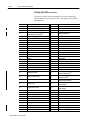
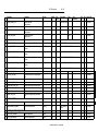
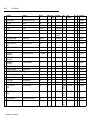
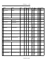
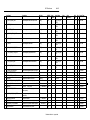
Data Item Format . . . . . . . . . . . . . . . . . . . . . . . . . . . . . . . . . . . . .
Data Type . . . . . . . . . . . . . . . . . . . . . . . . . . . . . . . . . . . . . . . . . .
Read/Write . . . . . . . . . . . . . . . . . . . . . . . . . . . . . . . . . . . . . . . . .
Array Indexes . . . . . . . . . . . . . . . . . . . . . . . . . . . . . . . . . . . . . . .
AXIS_NUM . . . . . . . . . . . . . . . . . . . . . . . . . . . . . . . . . . . . . . .
SPINDLE_NUM . . . . . . . . . . . . . . . . . . . . . . . . . . . . . . . . . . . .
NUM_CNC_DIRECTORIES . . . . . . . . . . . . . . . . . . . . . . . . . . .
SERVO_MODULES . . . . . . . . . . . . . . . . . . . . . . . . . . . . . . . . .
SERVO_NUM . . . . . . . . . . . . . . . . . . . . . . . . . . . . . . . . . . . . .
M_MODAL_GROUP . . . . . . . . . . . . . . . . . . . . . . . . . . . . . . . . .
G_MODAL_GROUP . . . . . . . . . . . . . . . . . . . . . . . . . . . . . . . . .
SETUP_BUFFERS . . . . . . . . . . . . . . . . . . . . . . . . . . . . . . . . .
NUM_PP_FILES . . . . . . . . . . . . . . . . . . . . . . . . . . . . . . . . . . .
OFFSET_NUM . . . . . . . . . . . . . . . . . . . . . . . . . . . . . . . . . . . .
TOOL_NUM . . . . . . . . . . . . . . . . . . . . . . . . . . . . . . . . . . . . . .
Control Type . . . . . . . . . . . . . . . . . . . . . . . . . . . . . . . . . . . . . . . .
Link Type . . . . . . . . . . . . . . . . . . . . . . . . . . . . . . . . . . . . . . . . . .
The OCI WatchList . . . . . . . . . . . . . . . . . . . . . . . . . . . . . . . . . .
Background/Foreground . . . . . . . . . . . . . . . . . . . . . . . . . . . . . . . .
Selecting the Process for Dual Process Controls . . . . . . . . . . . . . . .
Logical vs Physical Axes . . . . . . . . . . . . . . . . . . . . . . . . . . . . . . . .
AMP Parameter Data Items . . . . . . . . . . . . . . . . . . . . . . . . . . . . . .
Axis Calibration Data Items . . . . . . . . . . . . . . . . . . . . . . . . . . . . . .
Communication Port Data Items . . . . . . . . . . . . . . . . . . . . . . . . . .
Error Message Data Items . . . . . . . . . . . . . . . . . . . . . . . . . . . . . .
Miscellaneous Data Items . . . . . . . . . . . . . . . . . . . . . . . . . . . . . . .
Offset Data . . . . . . . . . . . . . . . . . . . . . . . . . . . . . . . . . . . . . . . . .
Operating Mode . . . . . . . . . . . . . . . . . . . . . . . . . . . . . . . . . . . . . .
4-1
4-2
4-2
4-3
4-4
4-4
4-4
4-5
4-5
4-6
4-6
4-7
4-7
4-8
4-8
4-8
4-9
4-11
4-13
4-14
4-15
4-16
4-18
4-21
4-33
4-38
4-43
4-46
iii
Table of Contents
Chapter 5
OCI Data Server CNC Commands
PAL Variable Data Items . . . . . . . . . . . . . . . . . . . . . . . . . . . . . . . .
Paramacro Variable Data Items . . . . . . . . . . . . . . . . . . . . . . . . . . .
Part Program Directory Data Items . . . . . . . . . . . . . . . . . . . . . . . .
Part Program Block Data Items . . . . . . . . . . . . . . . . . . . . . . . . . . .
Part Program Rotation and Scaling . . . . . . . . . . . . . . . . . . . . . . . .
Position Data Items . . . . . . . . . . . . . . . . . . . . . . . . . . . . . . . . . . .
Spindle Data Items . . . . . . . . . . . . . . . . . . . . . . . . . . . . . . . . . . . .
System Information Data Items . . . . . . . . . . . . . . . . . . . . . . . . . . .
Zones and Overtravels . . . . . . . . . . . . . . . . . . . . . . . . . . . . . . . . .
4-47
4-51
4-51
4-54
4-55
4-56
4-59
4-62
4-63
CNC Command Overview . . . . . . . . . . . . . . . . . . . . . . . . . . . . . . .
Command Arguments . . . . . . . . . . . . . . . . . . . . . . . . . . . . . . . . . .
Return Codes . . . . . . . . . . . . . . . . . . . . . . . . . . . . . . . . . . . . . . .
Selecting the Process . . . . . . . . . . . . . . . . . . . . . . . . . . . . . . . . . .
OCI Command Syntax . . . . . . . . . . . . . . . . . . . . . . . . . . . . . . . . .
AMP Commands . . . . . . . . . . . . . . . . . . . . . . . . . . . . . . . . . . . . .
MODIFYING_AMP (no argument) . . . . . . . . . . . . . . . . . . . . . . .
RESTORE_AMP (no argument) . . . . . . . . . . . . . . . . . . . . . . . .
TRANSFER_AMP_FROM_PORTA (no argument) . . . . . . . . . . .
TRANSFER_AMP_FROM_PORTB (no argument) . . . . . . . . . . .
TRANSFER_AMP_TO_PORTA (no argument) . . . . . . . . . . . . . .
TRANSFER_AMP_TO_PORTB (no argument) . . . . . . . . . . . . . .
TRANSFER_HOMECAL_TO_PORTA (no argument) . . . . . . . . .
TRANSFER_HOMECAL_TO_PORTB (no argument) . . . . . . . . .
TRANSFER_REVERSAL_ERROR_TO_PORTA (no argument) . .
TRANSFER_REVERSAL_ERROR_TO_PORTB (no argument) . .
UPDATE_AMP (no argument) . . . . . . . . . . . . . . . . . . . . . . . . . .
Axis Calibration . . . . . . . . . . . . . . . . . . . . . . . . . . . . . . . . . . . . . .
DELETE_ALL_AXISCAL_POINTS (no argument) . . . . . . . . . . . .
DELETE_AXISCAL_POINT (axis_num, axis_cal_point) . . . . . . . .
ENTER_AXISCAL_MODIFY_MODE (no argument) . . . . . . . . . .
EXIT_AXISCAL_MODIFY_MODE (no argument) . . . . . . . . . . . .
INITIALIZE_AXISCAL_TABLE (axis number, calibration_type,
calibration_start) . . . . . . . . . . . . . . . . . . . . . . . . . . . . . . . . .
INSERT_AXISCAL_POINT (axis_number) . . . . . . . . . . . . . . . . .
REPLACE_AXISCAL_VALUE (axis_number, axis_cal_point, value)
RESTORE_AXISCAL (no argument) . . . . . . . . . . . . . . . . . . . . .
STOP_AXISCAL (axis_number) . . . . . . . . . . . . . . . . . . . . . . . .
TRANSFER_AXISCAL_FROM_PORTA (no argument) . . . . . . . .
TRANSFER_AXISCAL_FROM_PORTB (no argument) . . . . . . . .
TRANSFER_AXISCAL_TO_PORTA (no argument) . . . . . . . . . . .
TRANSFER_AXISCAL_TO_PORTB (no argument) . . . . . . . . . . .
Communications . . . . . . . . . . . . . . . . . . . . . . . . . . . . . . . . . . . . .
AUX_COM_ABORT_COMMAND (no argument) . . . . . . . . . . . . .
AUX_COM_BACKUP_CONFIG_TABLE ("filename") . . . . . . . . . .
5-1
5-1
5-1
5-2
5-2
5-3
5-4
5-4
5-4
5-5
5-5
5-6
5-6
5-7
5-7
5-8
5-8
5-8
5-9
5-9
5-9
5-10
5-10
5-11
5-11
5-12
5-12
5-12
5-13
5-13
5-14
5-14
5-14
5-15
Publication 85206.6 - August 1999
iv
Table of Contents
AUX_COM_CMD_FWD_SEARCH (search_type, search_string")
AUX_COM_CMD_REV_SEARCH (search_type," search_string")
AUX_COM_CMDTBL_TO_FLASH (no argument) . . . . . . . . . . . .
AUX_COM_CONFIG_TO_FLASH (no argument) . . . . . . . . . . . .
AUX_COM_DOWNLOAD_FILE ("source_filename",
destination_filename") . . . . . . . . . . . . . . . . . . . . . . . . . . . .
AUX_COM_HOST_WRITE_TO_FLASH (no argument) . . . . . . . .
AUX_COM_SENDCMD (command_index) . . . . . . . . . . . . . . . . .
COPY_DEVICE_SETUP_DEFAULTS (port_ id, device_num ) . . .
DEACTIVATE_RIO_PASSTHROUGH (no argument) . . . . . . . . . .
ENTER_SERIAL_IO_MONITOR_MODE (`port_ id", com_mode")
EXIT_SERIAL_IO_MONITOR_MODE (no arguments) . . . . . . . . .
REPEAT_TX_SERIAL_IO (character) . . . . . . . . . . . . . . . . . . . .
SAVE_DEVICE_SETUP (no argument) . . . . . . . . . . . . . . . . . . .
SINGLE_TX_SERIAL_IO (character) . . . . . . . . . . . . . . . . . . . . .
START_SERIAL_IO_MONITOR (no arguments) . . . . . . . . . . . . .
STOP_SERIAL_IO_MONITOR (no arguments) . . . . . . . . . . . . . .
Miscellaneous . . . . . . . . . . . . . . . . . . . . . . . . . . . . . . . . . . . . . . .
CALCULATE("calc_string") . . . . . . . . . . . . . . . . . . . . . . . . . . . .
CLEAR_ACTIVE_ERRORS (no argument) . . . . . . . . . . . . . . . . .
CLEAR_CYCLE_TIME (no argument) . . . . . . . . . . . . . . . . . . . .
CLEAR_ERROR_LOG (no argument) . . . . . . . . . . . . . . . . . . . .
CLEAR_POWER_ON_TIME_OVERALL (no argument) . . . . . . . .
CLEAR_RUNTIME (no argument) . . . . . . . . . . . . . . . . . . . . . . .
CLEAR_WORKPIECES_CUT_OVERALL (no argument) . . . . . . .
INPUT_MDI_STRING ("text_string") . . . . . . . . . . . . . . . . . . . . .
REFORMAT_MEMORY (no arguments) . . . . . . . . . . . . . . . . . . .
RELINQUISH_CONTROL (no argument) . . . . . . . . . . . . . . . . . .
REQUEST_CONTROL (no argument) . . . . . . . . . . . . . . . . . . . .
RESET_MAX_TIMES (no argument) . . . . . . . . . . . . . . . . . . . . .
STORE_OEM_MESSAGE (no arguments) . . . . . . . . . . . . . . . . .
Offsets . . . . . . . . . . . . . . . . . . . . . . . . . . . . . . . . . . . . . . . . . . . .
ACTIVATE_TOOL_LENGTH (offset_number) . . . . . . . . . . . . . . .
ACTIVATE_TOOL_RADIUS (offset_number) . . . . . . . . . . . . . . .
ACTIVATE_TOOL_WEAR (offset_number) . . . . . . . . . . . . . . . . .
ACTIVATE_WHEEL_GEOM (offset_number) . . . . . . . . . . . . . . .
ACTIVATE_WHEEL_RADIUS (offset_number) . . . . . . . . . . . . . .
BACKUP_ALL_OFFSETS ("Filename_string") . . . . . . . . . . . . . .
BACKUP_INTERF_TABLE ("Filename_string") . . . . . . . . . . . . . .
BACKUP_RADIUS_TABLE ("Filename_string") . . . . . . . . . . . . .
BACKUP_TOOL_GEOM ("Filename_string") . . . . . . . . . . . . . . .
BACKUP_TOOL_WEAR ("Filename_string") . . . . . . . . . . . . . . .
BACKUP_WHEEL_GEOMETRY ("Filename_string") . . . . . . . . . .
BACKUP_WORK_COORD ("Filename_string") . . . . . . . . . . . . .
COPY_OFFSET ("source_axis, destination_axis") . . . . . . . . . . .
MEASURE_TOOL_GEOM (tool_number, axis_number, ref_pos) .
Publication 85206.6 - August 1999
5-15
5-16
5-16
5-16
5-17
5-17
5-17
5-18
5-18
5-18
5-19
5-19
5-20
5-20
5-20
5-21
5-21
5-21
5-21
5-22
5-22
5-22
5-22
5-22
5-22
5-23
5-23
5-23
5-24
5-24
5-24
5-25
5-25
5-26
5-26
5-27
5-27
5-28
5-28
5-29
5-29
5-30
5-30
5-31
5-31
Table of Contents
v
MEASURE_TOOL_WEAR (tool_number, axis_number, ref_pos) . 5-32
MEASURE_WHEEL_GEOM (tool_number, axis_number, ref_pos) 5-32
PAL Commands . . . . . . . . . . . . . . . . . . . . . . . . . . . . . . . . . . . . . . 5-33
TRANSFER_PAL_FROM_PORTB (no argument) . . . . . . . . . . . . 5-34
TRANSFER_PAL_TO_PORTA (no argument) . . . . . . . . . . . . . . . 5-34
TRANSFER_PAL_TO_PORTB (no argument) . . . . . . . . . . . . . . 5-35
Paramacro Commands . . . . . . . . . . . . . . . . . . . . . . . . . . . . . . . . . 5-35
BACKUP_COM1_PARAMETERS ("Filename_string") . . . . . . . . . 5-36
BACKUP_COM2A_PARAMETERS ("Filename_string") . . . . . . . . 5-36
BACKUP_COM2B_PARAMETERS ("Filename_string") . . . . . . . . 5-37
BACKUP_SHARED_PARAMETERS ("Filename_string") . . . . . . . 5-37
Part Program Commands . . . . . . . . . . . . . . . . . . . . . . . . . . . . . . . 5-38
COPY_PART_PROGRAM (`src_filename_string", dest_filename
_string") . . . . . . . . . . . . . . . . . . . . . . . . . . . . . . . . . . . . . . . 5-38
COPY_MEM_TO_MEM (`src_filename_string", dest_filename_string",
mode) . . . . . . . . . . . . . . . . . . . . . . . . . . . . . . . . . . . . . . . . 5-39
COPY_MEM_TO_PORTA (`src_filename_string", dest_name",
mode) . . . . . . . . . . . . . . . . . . . . . . . . . . . . . . . . . . . . . . . . 5-40
COPY_MEM_TO_PORTB (`src_filename_string", dest_name",
mode) . . . . . . . . . . . . . . . . . . . . . . . . . . . . . . . . . . . . . . . . 5-40
COPY_PORTA_TO_MEM (src_name",`dest_filename_string",
mode) . . . . . . . . . . . . . . . . . . . . . . . . . . . . . . . . . . . . . . . . 5-41
COPY_PORTB_TO_MEM (`src_name", dest_filename_string",
mode) . . . . . . . . . . . . . . . . . . . . . . . . . . . . . . . . . . . . . . . . 5-42
DEACTIVATE_PART_PROGRAM (no argument) . . . . . . . . . . . . 5-43
DELETE_PART_PROGRAM (filename_string") . . . . . . . . . . . . . 5-43
ENTER_PART_PROGRAM_SEARCH_MODE (search_type) . . . . 5-43
EXECUTE_PART_PROGRAM_SEARCH (Search Method) . . . . . 5-44
RENAME_PART_PROGRAM (src_filename_string",
dest_filename_string") . . . . . . . . . . . . . . . . . . . . . . . . . . . . 5-44
RESTART_PART_PROGRAM (restart_action) . . . . . . . . . . . . . . 5-45
SEQUENCE_STOP_PART_PROGRAM (block_num) . . . . . . . . . 5-45
SET_DIRECTORY (target_dir, password_string") . . . . . . . . . . . . 5-46
SET_PART_PROGRAM_COMMENT (`filename_string",
text_string") . . . . . . . . . . . . . . . . . . . . . . . . . . . . . . . . . . . . 5-46
SET_PART_PROGRAM_INPUT_DEVICE (pp_source) . . . . . . . . 5-47
SET_PART_PROGRAM_SEARCH_PATTERN (text_string") . . . . 5-47
VERIFY_PART_PROGRAM ("filename1", filename2", mode) . . . 5-48
VERIFY_WITH_PORTA ("filename1", mode) . . . . . . . . . . . . . . . 5-49
VERIFY_WITH_PORTB ("filename1", mode) . . . . . . . . . . . . . . . 5-50
Part Program Execution . . . . . . . . . . . . . . . . . . . . . . . . . . . . . . . . 5-51
EXECUTE_MIDSTART_SEARCH (search_method) . . . . . . . . . . 5-51
SET_MIDSTART_SEARCH_PATTERN ("search_string") . . . . . . . 5-52
STOP_QUICK_CHECK (no argument) . . . . . . . . . . . . . . . . . . . . 5-52
SYNTAX_QUICK_CHECK (no argument) . . . . . . . . . . . . . . . . . . 5-53
Tool Management/Random Tool . . . . . . . . . . . . . . . . . . . . . . . . . . 5-53
BACKUP_RANDOM_TOOL ("Filename_string") . . . . . . . . . . . . . 5-54
Publication 85206.6 - August 1999
vi
Table of Contents
Chapter 6
Array Indices and Strings
Publication 85206.6 - August 1999
BACKUP_TOOL_MANAGE ("Filename_string") . . . . . . . . . . . . .
RT_CUSTOMIZE_TOOL (pocket_number, pockets_needed,
shaft_pocket) . . . . . . . . . . . . . . . . . . . . . . . . . . . . . . . . . . .
RT_SET_TOOL_NUM (tool_number, pocket_number) . . . . . . . . .
TM_DELETE_ALL (no argument) . . . . . . . . . . . . . . . . . . . . . . .
TM_DELETE_GROUP (tool_group_num) . . . . . . . . . . . . . . . . . .
TM_DELETE_TOOL (tool_group_num, entry_num) . . . . . . . . . . .
TM_INSERT_TOOL (tool_group_num, tool_num, entry_num) . . .
5-54
5-55
5-56
5-56
5-56
5-57
5-57
Variable Ranges . . . . . . . . . . . . . . . . . . . . . . . . . . . . . . . . . . . . .
Enumerations . . . . . . . . . . . . . . . . . . . . . . . . . . . . . . . . . . . . . . .
ACTIVE_RADIUS_DIAMETER_MODE enumeration . . . . . . . . . .
AMP_DATA_TYPE enumeration . . . . . . . . . . . . . . . . . . . . . . . .
AUX_COM_REM_STATION_TYPE enumeration . . . . . . . . . . . .
AUX_COM_SEARCH_TYPE enumeration . . . . . . . . . . . . . . . . .
BACK_BORING_SHIFT_DIRECTION enumeration . . . . . . . . . . .
CALIBRATION_START enumeration . . . . . . . . . . . . . . . . . . . . .
CALIBRATION_TYPE enumeration . . . . . . . . . . . . . . . . . . . . . .
COM_MODE enumeration . . . . . . . . . . . . . . . . . . . . . . . . . . . .
COPY_MEM_TO_PORTA/B (copy to type) enumeration . . . . . . .
COPY_PORTA/B_TO_MEM (copy from type) enumeration . . . . .
DOWNLOAD_IN_PROGRESS enumeration . . . . . . . . . . . . . . . .
DH_CHANNEL_TYPE enumeration . . . . . . . . . . . . . . . . . . . . . .
DH_COMMAND enumeration . . . . . . . . . . . . . . . . . . . . . . . . . .
DH_BAUD_RATE enumeration . . . . . . . . . . . . . . . . . . . . . . . . .
DH_OUTPUT_FORMAT enumeration . . . . . . . . . . . . . . . . . . . .
DH_PARITY enumeration . . . . . . . . . . . . . . . . . . . . . . . . . . . . .
DH_REMOTE_STATION enumeration . . . . . . . . . . . . . . . . . . . .
ERROR_MESSAGE_TYPE enumeration . . . . . . . . . . . . . . . . . .
MACHINE_TYPE enumeration . . . . . . . . . . . . . . . . . . . . . . . . .
MID_START_ACTION enumeration . . . . . . . . . . . . . . . . . . . . . .
MID_START_TYPE enumeration . . . . . . . . . . . . . . . . . . . . . . . .
MODE_ACTIVE (active mode) enumeration . . . . . . . . . . . . . . . .
MODE_FEED (feed mode) enumeration . . . . . . . . . . . . . . . . . . .
MODE_INCH/METRIC (inch/metric mode)enumeration . . . . . . . .
OPTION_SELECTED_INDICES enumeration . . . . . . . . . . . . . . .
PORT_BAUD_RATE enumeration . . . . . . . . . . . . . . . . . . . . . . .
PORT_COMM_FORMAT enumeration . . . . . . . . . . . . . . . . . . . .
PORT_DATA_BITS enumeration . . . . . . . . . . . . . . . . . . . . . . . .
PORT_PARITY enumeration . . . . . . . . . . . . . . . . . . . . . . . . . . .
PORT_ID enumeration . . . . . . . . . . . . . . . . . . . . . . . . . . . . . . .
PORT_TYPE enumeration . . . . . . . . . . . . . . . . . . . . . . . . . . . .
PORTA_DEVICE enumeration . . . . . . . . . . . . . . . . . . . . . . . . . .
PORTB_DEVICE enumeration . . . . . . . . . . . . . . . . . . . . . . . . .
PORT_PROTOCOL enumeration . . . . . . . . . . . . . . . . . . . . . . .
6-1
6-1
6-1
6-2
6-2
6-2
6-3
6-3
6-3
6-4
6-4
6-4
6-5
6-5
6-5
6-6
6-6
6-6
6-7
6-7
6-8
6-8
6-8
6-9
6-9
6-9
6-10
6-11
6-11
6-11
6-12
6-12
6-12
6-13
6-14
6-14
Table of Contents
Appendix A
OCI Data Items
vii
PORT_STOP_BITS enumeration . . . . . . . . . . . . . . . . . . . . . . . .
PORT_TAPE_MULTI enumeration . . . . . . . . . . . . . . . . . . . . . . .
PORT_TIMEOUT_VALUE enumeration . . . . . . . . . . . . . . . . . . .
PP_SOURCE enumeration . . . . . . . . . . . . . . . . . . . . . . . . . . . .
PRODUCT_ID enumeration . . . . . . . . . . . . . . . . . . . . . . . . . . .
ROTATION_EXT_STATUS enumeration . . . . . . . . . . . . . . . . . . .
SCALING_INDICATOR enumeration . . . . . . . . . . . . . . . . . . . . .
SEARCH_METHOD enumeration . . . . . . . . . . . . . . . . . . . . . . .
SEARCH_TYPE enumeration . . . . . . . . . . . . . . . . . . . . . . . . . .
SERVO_STATUS enumeration . . . . . . . . . . . . . . . . . . . . . . . . .
SYSTEM_STATE enumeration . . . . . . . . . . . . . . . . . . . . . . . . .
TARGET_DIR enumeration . . . . . . . . . . . . . . . . . . . . . . . . . . . .
TM_STATUS enumeration . . . . . . . . . . . . . . . . . . . . . . . . . . . .
TM_GRAPHICS_TOOL_COLOR enumeration . . . . . . . . . . . . . .
UART_A/B BUSY_STATUS enumeration . . . . . . . . . . . . . . . . . .
Strings . . . . . . . . . . . . . . . . . . . . . . . . . . . . . . . . . . . . . . . . . . . .
TEXT_STRING string . . . . . . . . . . . . . . . . . . . . . . . . . . . . . . .
6-15
6-15
6-15
6-16
6-16
6-16
6-16
6-17
6-17
6-17
6-18
6-18
6-18
6-19
6-19
6-19
6-20
OCI Error Handling Overview . . . . . . . . . . . . . . . . . . . . . . . . . . . .
API Data Request Errors . . . . . . . . . . . . . . . . . . . . . . . . . . . . .
Command and Data Item POKE Errors . . . . . . . . . . . . . . . . . . .
C-1
C-1
C-1
Appendix B
OCI Commands
Appendix C
OCI Error Handling
Publication 85206.6 - August 1999
Chapter
1
Open Control Interface (OCI)
Overview
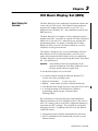
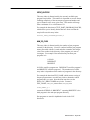
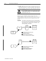
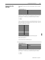
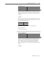
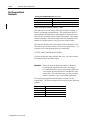
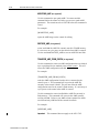
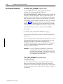
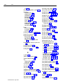
OCI Data Server Overview
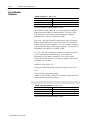
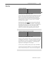
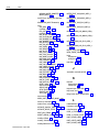
This chapter contains an overview of the OCI system and how it uses
Windows DDE and RSLinx software to establish
communications between the OCI data server and the 9/Series or
9/PC CNCs.
Once the OCI data server and RSLinx software for 9/Series CNCs
have been configured and launched, your DDE–compliant
application (for example the OCI Basic Display Set) can read and
write data and execute commands on networked CNCs.
Your DDE-compliant applications can access the data from the OCI
data server by establishing a DDE link to the Server through the
application’s link function. The basic display set uses the
RSJunctionBoxt utility for AdvancedDDE communications.
RSJunctionBox is optional for your own application based upon your
applications performance requirements.
The OCI data server uses RSLinx software to access the processor(s)
through Windows TCP/IP Ethernet tools. This access does not apply
for the 9/PC.
Publication 8520-6.6 - August 1999
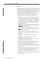
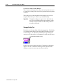
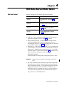
1–2
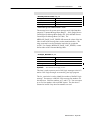
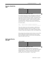
Open Control Interface (OCI) Overview
For 9/Series
Your DDE compliant
Application
For 9/PC
9/Series Basic
Display Set
Your DDE compliant
Application
RSJunctionBox
RSJunctionBox
9/Series OCI
Data Server
9/Series Basic
Display Set
OCI CNC part Program
File Handler
OCI Data
Server
OCI CNC Part Program
File Handler
RSLinx
abcnccom.dll
Ethernet
9/PC Support
Service
9/Series
Processor(s)
9/PC
PCI Drivers)
PCI Bus
9/PC
Processor
Your DDE Compliant
Application Program
Your application program is your DDE–compliant
Microsoft-Windows based application. This application provides
the interface between your personal computer and the OCI data
server. The application can range from the more complex, such as a
compiled Microsoft Visual Basic executable which can provide the
entire operator interface to your 9/Series or 9/PC, to a simple
Microsoft-Excel spread sheet with only a few DDE calls used for
data collection.
The Basic Display Set included with the OCI package is an example
of a DDE compliant application program. The basic display set is a
compiled visual basic program and is discussed later in this manual.
The visual basic source code for these default screens is available as
an option through your Allen-Bradley sales office.
Publication 8520-6.6 - August 1999
Open Control Interface (OCI) Overview
1–3
DDE Overview
DDE is a method used by Microsoft Windows to accomplish
process-to-process communications. This common protocol allows a
DDE-compliant Windows application to communicate with another
DDE-compliant Windows application. DDE has been a part of
Windows since version 2.0 and is supported by many of the most
popular Windows application packages, such as MS Excel and MS
Word for Windows.
The implementation of DDE uses a data server (called the OCI data
server) to send and receive data from the CNC. This data server
provides a DDE interface so other DDE compliant Windows
applications can access data as though the CNC information was
from a local DDE device.
A DDE application must provide three pieces of information to
access a single piece of data from the OCI DDE data server:
• Service or Application name
• Topic name
• Item name
The service for your DDE application will be the Allen–Bradley OCI
DDE data server. The name for this service is:
ABOCISERVER
For the Allen-Bradley OCI data server, a topic is an ethernet alias for
a specific 9/Series CNC. Refer to your OCI Installation Guide for
details on establishing 9/Series ethernet topic names. This alias is
identified in the OCIDSCFG.INI file as the TopicId.
For 9/PC CNCs, the topic name is used to identify a 9/PC (located in
the host computer) to facilitate communication between the 9/PC
CNC executive and various client applications and services running
on a PC. TopicId for the 9/PC CNC is set in the Configuration
Manager.
An item is either a data item or a command item. Data items are
listed starting on page 4–1 and are used to read and write data
from/to your CNC. Command items are listed starting on page 5–1
and are used to request the 9/Series CNC perform a specific task.
Publication 8520-6.6 - August 1999
1–4
Open Control Interface (OCI) Overview
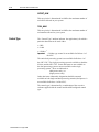
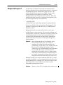
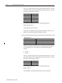
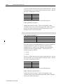
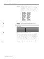
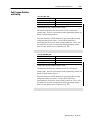
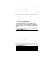
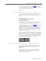
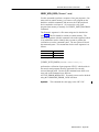
To access a piece of data named num_axes on a specific CNC, you
enter this information into your application’s DDE Link function:
Service (or Application) Name
Topic Name
Item Name
ABOCISERVER
CNC_1
NUM_AXES
Once you specify this information in your application program and
execute the request, the application establishes a link to the OCI data
server and requests the data or command.
The OCI Data Server
Once installed and executing, the OCI data server is used to converse
between a 9/Series CNC (using RSLinx) or 9/PC CNC and your
application program (using DDE). Refer to your OCI Installation
Manual or 9/PC Installation and Integration Manual for details on
OCI installation and configuration.
The OCI data server provides a DDE interface for your application
program from a specific CNC. The service name for the OCI data
server is:
ABOCISERVER
The OCI data server runs in the Microsoft Windows NT
(4.0 or higher) operating environment.
OCI Data Server Read Data Requests
Your OCI application can request data from the CNC. Read requests
can be automatic or manual. Automatic items are added and
maintained on a watchlist at the control. Manual items are placed on
the watchlist just long enough to report the current value of the item.
Refer to page 4–1 for details on reading data items.
OCI Data Server Write Data Requests
Information can be written to your CNC using a Poke operation.
When a Poke request is made by your application program to the
OCI data server, the data server passes this data on to the CNC
processor which (if valid) will change the data item value.
Publication 8520-6.6 - August 1999
Open Control Interface (OCI) Overview
1–5
Poke requests are only honored by the CNC when they are made
from the data servers controlling OCI station. Refer to the API data
item chapter in this manual for details on requesting control.
!
ATTENTION: Extreme care must be taken when
using the POKE capability. If you inadvertently write
bad data to a critical 9/Series or 9/PC configuration,
you could adversely affect the operation of the CNC.
OCI Data Server Command Requests
Your OCI application can request the CNC to execute a command.
A description of the available CNC OCI commands begins on
page 5–1. Commands ask the control to perform specific tasks such
as download a part program or reformat the RAM disk. When your
application program requests a command be executed for a specific
CNC, the OCI data server passes this command on to the CNC which
will (if valid) execute the command.
OCI Data Server Return and Error Codes
CNCs that are off-line or powered down will not respond to the
requests that the OCI data server is sending them. The OCI data
server will retry a read, write, or command transaction if the
processor is on-line but currently busy. If the OCI data server detects
a severe error, such as no response from the processor, the OCI data
server will stop trying to communicate to the device. After a time
specified in the 9/Series data server’s INI file for the 9/Series CNCs
and in the Configuration Manager for 9/PC CNCs, the OCI data
server will again try to contact the processor. If it fails again, the OCI
data server will repeat the process until the failure no longer exists.
Important:
The 9/PC data server is configured via the 9/PC
Configuration Manager.
The retries will affect OCI data server performance, since they entail
additional OCI data server communications.
When your OCI application requests either a data item or issues a
command to the CNC through the OCI data server the request is
either performed or rejected by the CNC.
Publication 8520-6.6 - August 1999
1–6
Open Control Interface (OCI) Overview
Status of Commands and POKE Data Items
When a data item read is successful no return code is sent to the
OCI, only the requested data is sent. When a data item or command
write is requested, the control will send a return code indicating that
the request was successful or failed. API data item POKE request
status is returned to the OCI in the reserved data item
“WRITE_ERROR_CODE”. Command status is returned to the OCI
in the reserved data item COMMAND_ERROR.
See page C–1 for details on error handling.
Errors on Automatic Items
When your OCI application requests a data item as automatic, the
OCI data server requests that item be added to the watchlist on the
specified CNC (refer to the data item chapter in this manual for
details on the CNC watchlist). If this data item is invalid for some
reason (e.g. bad syntax, not a valid item, watchlist full) the control
will return an error to the OCI data server indicating the error and the
item was not added to the watchlist. These errors are returned as text
to the requesting DDE object (e.g., Server Error [29]). See Chapter
3 for details on how we use a CNC based watchlist for automatic
items.
Errors on Manual Items
When your OCI application requests a data item as manual, the OCI
data server requests a value for that item from the specified CNC. If
the data item is invalid the control will return an error to the OCI
data server indicating the error condition. These errors are returned
as text to the requesting DDE object (e.g. Server Error [29]).
RSLinx OEM
RSLinx OEM is installed on your windows workstation as an
integral part of a complete OCI system. This Rockwell Software
utility provides the OCI DDE data server access to the 9/Series CNC
through an ethernet connection.
A copy of RSLinx OEM comes with each OCI system you purchase
from Allen–Bradley. RSLinx is not included with the development
tool. For each OCI station that you create or ship you must purchase
an additional RSLinx license for that station. Contact your Rockwell
Automation sales representative for additional RSLinx licenses.
Publication 8520-6.6 - August 1999
Open Control Interface (OCI) Overview
Your Development Tool
(Visual Basic)
Special API Development
Tools
1–7
Many development tools are available to enhance your machine
interface as well as document machine statistics, etc. This manual is
written assuming the use of Microsoft’s Visual Basic development
tool.
When we developed the basic display set we took advantage of
several special development tools to simplify development and
improve performance of our application.
RSLinx JBOX and RSData.OCX
The basic display set was developed using a sub–set of Rockwell
Softwares RSTools development kit. This development tool
provides many custom controls that will improve the look of your
final application as well as enhance performance.
The basic display set makes extensive use of the RSData.OCX
custom control. This control is used in place of standard windows
DDE text transfers for most of the data links to the OCI data server.
This custom OCX dramatically improves the speed at which DDE
data is transferred.
Included with the basic display set package is the JBOX.DLL which
is required to allow this custom control to function. You must
include this DLL with any OCI software you ship that uses the basic
display set.
Included with the API development package is a subset of RSTools
called RSData which provides the custom OCX control to add to
your visual basic development tool and the JBox.DLL necessary to
make this application work.
Refer to your RSData user’s guide for details.
Publication 8520-6.6 - August 1999
1–8
Open Control Interface (OCI) Overview
JBoxDestroyInactiveParts
When an item is requested of the OCI data server using the RSdata
JBox control it is added to the watchlist on the specified control.
Because of the nature of more typical JBox applications when the
request for this data from the application no longer exists JBox does
not normally terminate the request for this item. Since watchlist
space on the CNC is limited even a small application will quickly
run out of watchlist space. To prevent this scenario we used an
undocumented attribute of JBox called JBoxDestroyInactiveParts.
This attribute will remove any inactive automatic links from the data
server which than removes it from the CNC watchlist.
Since JBoxDestroyInactiveParts is not a documented feature of JBox
you will not find it in any property sheet or attribute of a JBox
control. We used this feature by first making the declaration:
Declare Sub JBoxDestroyInactiveParts Lib “RSJBOX32.dll” (bDestroyInactive as Long)
Than calling the function in the mainMDI form Load routine:
JBoxDestroyInactiveParts (True)
Important:
This function call must be made only after the first
RSData link data item is placed as an Automatic Item in
the watch list.
OCI Basic Display Set Source Code Routines
The OCI basic display set source code contains many useful
subroutines that will make data retrieval, command requests, and
data formatting simpler. Refer to page 3–1 for details on this source
code and its subroutines. Printing functions and debugging routines
are also available in this source code.
Publication 8520-6.6 - August 1999
Chapter
2
DDE Data Server Examples
DDE Conversation
Overview
This chapter assumes you have:
• Already installed your 9/Series or 9/PC OCI software on your
machine
• Configured your INI files properly (OCI) (9/Series only)
•
•
•
•
Configured your 9/PC via the 9/PC Configuration Manager
Made proper Ethernet connections with your 9/Series (OCI only)
Run your OCI data server without errors
Confirmed your communication is working, for OCI by using the
OCI testing tool (refer to your 9/Series OCI Installation Manual
for information about parsercl.exe), and for 9/PC by using the
9/PC Installation and Integration Manual
A DDE conversation with the data service can be established using
any Windows–compliant application that supports Microsoft’s
Dynamic Data Exchange functions. This chapter gives examples of
such conversations established using Microsoft’s Visual Basic and
Microsoft’s Excel.
A DDE conversation, regardless of the software used to start the
communication, requires the following three things:
1. A DDE Server or Application Name
2. A Topic Name to that server
3. A Data Item or Command to pass to that server
DDE Server
For the 9/Series or 9/PC, the DDE server is always:
“ABOCISERVER”
This is the server name registered in Windows when you launch the
9/Series or 9/PC OCI data server.
Publication 8520-6.6 - August 1999
2–2
DDE Data Server Examples
Topic Name
The topic name is created by the data server when it is launched.
9/Series only topic names are defined by you in the INI file
OCIDSCFG.INI. A different topic name is created for each 9/Series
CNC connection to the data server as an alias. If you are using the
9/PC, you create the topic name during 9/PC executive software
installation or change the topic name via the 9/PC Configuration
Manager. The 9/PC has only one topic name. The default alias for
one CNC connection is:
“CNC_1”
The rest of this chapter assumes this is the alias you are using. Refer
to your 9/Series OCI Installation Manual for details on configuring
the INI file for 9/Series OCI or the Configuration Manager in the
9/PC Installation and Integration Manual for configuring the 9/PC.
Item Name
The item name for the 9/Series or 9/PC data server can be either a
data item (refer to chapter 3 or appendix A) or a command (refer to
chapter 4 or appendix B). For example:
AVAILABLE_MEMORY
Is the valid name of an OCI topic that returns free memory
information from the 9/Series or 9/PC.
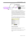
Using Visual Basic
Several different VB objects can be used to create DDE links to a
DDE server. Refer to your VB instruction manual for these items.
For the following example we created a text box on the VB form and
named that text box ”X_RAW”. This text box then stores the data
returned from the data server (X_RAW.Text). It is important to
remember that if the command fails or is invalid for some reason the
string “Server Error [code]” for the connection will also be returned
as the text value for this text box. Your code should test the value of
your DDE objects to identify and handle errors appropriately.
Reading Data
In Microsoft Visual Basic the Service and Topic are included in the
same property separated by a pipe character and enclosed in quotes.
This example simply gets the raw value of the axis 1 position (no
decimal point). Later you’ll need to format this data as determined
by your system configuration before passing it on to users.
Publication 8520-6.6 - August 1999
DDE Data Server Examples
2–3
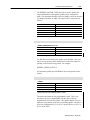
X_raw.LinkTopic = ”abociserver|CNC_1” ’Set Link Service and Topic
X_raw.LinkItem = ”axis_position_prg,1” ’Sets Link Item to axis1 program position
X_raw.LinkMode = 1 ’Sets link mode to automatic so 9/Series will update data
’X_raw.LinkRequest Establishes the connection if manual link had been requested
Once these four lines of code are executed, the value (X_raw.Text)
will automatically be updated by the 9/Series or 9/PC whenever the
data changes. This is accomplished by the 9/Series or 9/PC adding
this data item to a watch list stored on the 9/Series or 9/PC. When a
piece of data changes that’s included on the watchlist the 9/Series or
9/PC automatically passes the new value to the OCI data server
which then passes it on to the appropriate application (in our case
Visual Basic).
Writing Data (POKE)
This example waits for a command button to be clicked by the
operator to place the control in E–STOP. Since a command button is
not a DDE conversation tool, a text box was also created on the form
named ”E_STOP”. To place the control in E–Stop a 1 is written to
the PAL/Logic flag $ESTOP. Like a DDE read the Write data is also
stored as the text of the text box. The following code was placed in
the Click event of the command button. Writing of data takes place
when the LinkPoke request is made to the text box.
E_Stop.LinkTopic = ”abociserver|CNC_1” ’Set Link Service and Topic
E_Stop.LinkItem = ”$ESTOP”
’Sets Link Item to PAL/Logic ESTOP flag
E_Stop.LinkMode = 2 ’Sets the link mode to manual
E_Stop.Text = 1 ’Places the data to write into the text box
E_Stop.LinkPoke ’Writes the value 1 to $ESTOP
E_Stop.LinkMode = VBLinkNone ’breaks the manual connection
Note that since we are using a PAL/Logic flag in this example the
control’s PAL/Logic program still has the ability to overwrite items
sent to the control. PAL/Logic always wins when conflicting writes
occur to a flag since they are written immediately before the
PAL/Logic scan. In this case unless your PAL program is written to
repeatedly write a zero to $ESTOP every scan or to write a
True–or–False to your Logic program, it shouldn’t be a problem but
you should keep it in mind when writing to PAL/Logic variables
through the OCI DDE interface.
Publication 8520-6.6 - August 1999
2–4
DDE Data Server Examples
DDE Commands
In this example we execute a DDE command that writes MDI data to
the CNC. The user places the program block in a text box we
created on the form named ”MDI_Input”. Commands are always
placed between square brackets [ ]. This example uses the
”INPUT_MDI_STRING” command. Commands can be found in
chapter 4 or appendix B. The following code is executed when a
command button is pressed.
MDI_Input.LinkTopic = ”abociserver|CNC_1” ’Set Link Service and Topic
MDI_Input.LinkMode = 1 ’Set Link Mode to Automatic
MDI_Input.LinkExecute (”[input_mdi_string(” & Chr$(34) & MDI_Input.Text & _
Chr$(34) & ”)]”)
MDI_Input.LinkMode = vbLinkNone
Using Microsoft Excel
MS Excel is also capable of performing DDE conversations with the
OCI data server. This can prove a useful tool to collect data for
statistical analysis of your machine process. The following example
shows a cell in Excel that is used to store the accumulated tool life
though any valid OCI DDE could be substituted for the item name.
The syntax for a DDE call in Excel is all placed as an equation in the
desired cell. The equation defines the DDE Application, Topic, and
data item. The equation syntax is as follows:
=Application|Topic!’ItemName’
The following is an example of an Excel cell that returns the
accumulated tool life for tool number 3.
=ABOCISERVER|CNC_1!’TM_ACCUMULATED_LIFE,3’
Publication 8520-6.6 - August 1999
Chapter
3
OCI Basic Display Set (BDS)
Basic Display Set
Overview
The Basic Display Set is the standard OCI application software that
comes with your OCI system. This Windows–based application
program is the standard operator interface to your CNC. It is
designed to run in Windows NT and communicates with the OCI
DDE data server.
The Basic Display Set is designed to closely emulate the 9/Series
standard front panel. For details on using the OCI Basic Display Set
(BDS) refer to your OCI User’s Manual and your operation and
programming manual. For details on installing the OCI Basic
Display Set refer to your OCI Installation Manual or your 9/PC
Installation and Integration Manual.
This chapter is designed to give you an understanding of how the
Basic Display Set was developed and make it easier for you to
modify and customize the Basic Display Set for your application.
The Basic Display Set was developed using Microsoft’s Visual Basic
Pro development tool.
Important:
Allen–Bradley assumes no responsibility for the
operation and function of the Basic Display Set once it
has been modified from its original form.
To edit the Basic Display Set you will need:
• A personal computer running the Microsoft Windows NT
(version 4.0 or later) operating system
•
•
•
•
Microsoft Visual Basic (version 5.0 or 6.0)
RSData custom control (a product of Rockwell Software)
Allen Bradley Basic Display Set source code disks (OCI or 9/PC)
A working knowledge of Visual Basic Pro, Windows
programming, and the concepts of Dynamic Data
Exchange (DDE)
We recommend your personal computer be linked through an
Ethernet connection to an OCI–compatible 9/Series CNC or have a
9/PC CNC running (please use the 9/PC Configuration Manager to
ensure that the 9/PC is running). This is helpful for writing and
debugging your edits. In addition to the above list this optional
connection requires:
• Appropriate personal computer ethernet hardware and drivers
• An OCI compatible 9/Series installed and powered up on the
Ethernet network
Publication 8520-6.6 - August 1999
3–2
OCI Basic Display Set (BDS)
Important:
The 9/PC CNC does not use Ethernet connections. If
you are using a 9/PC CNC, we recommend that you
use the 9/PC Configuration Manager to make sure your
9/PC is running.
• Rockwell Softwares JunctionBox executable
• The OCI data server installed, running, and communicating to the
OCI–compatible CNC (necessary to use the softkey and other
provided editor utilities).
Not having your personal computer connected to your CNC will
cause data errors any time you run code for a screen that contains a
DDE call to a data item or command.
Installing the Source Code
The Basic Display Set was developed using Microsoft Visual Basic
Pro development tool. You should be familiar with Visual Basic
Pro, Windows programming, and the concepts behind dynamic data
exchange (DDE).
The source code for the Basic Display Set comes on 3.5–inch floppy
disks labeled “Basic Display Set Source Code”. Use the following
procedure to import this source code to your Visual Basic
Application:
1. Insert the first disk of the Basic Display Set source code into your
disk drive.
2. Select the “Run” option from the Start menu.
3. Enter in the Run dialog:
A:SETUP
where A: is the name of the drive containing disk one of the Basic
Display Set source code.
4. Follow the setup instructions as prompted on the screen.
Important:
Publication 8520-6.6 - August 1999
During the setup process you will be prompted for a
destination directory for this source code. It is
important that you choose the same directory that was
used to load the Basic Display Set executable. The
Basic Display Set executable installation contains data
files (not included with the source code) that are
necessary to build a working OCI system. The default
setup directory for both the Basic Display Set
executable and source code is C:\ABOCI or c:\ab9PC
depending on the system the Basic Display Set was
developed for (9/Series or 9/PC).
OCI Basic Display Set (BDS)
3–3
When the setup utility is complete the Visual Basic Pro project file
ABOCI.VBP is installed in the source code directory. Before you
can open this project in Visual Basic, you must first install the
custom OCX called RSData. This custom OCX is an improved DDE
tool used extensively in the Basic Display Set source code.
Installing RSData Custom
OCX
RSData is a Microsoft OLE custom control (OCX) created by
Rockwell Software. The RSData control is designed to be used with
any Dynamic Data Exchange Server and provides enhanced
performance when used with applications that conform to
AdvanceDDE protocol. This custom OCX is used extensively in
the Basic Display Set source code.
The RSData OCX uses a high speed DDE communications module
called RSJunctionBox. RSJunctionBox allows RSData to
communicate with the OCI DDE data server with considerably
higher performance than standard DDE communications provide.
To install the RSData Custom OCX and the RSJunctionBox DDE
communications module follow the instructions that accompanied
these Rockwell Software products.
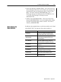
Source Code Directory
Structure
The Basic Display Set pulls data from a variety of subdirectories
created during the setup of both the Basic Display Set executable and
source code. This directory structure must be maintained to properly
compile the source code. These subdirectories of the source code are
as follows:
This Directory:
Contains this Data
ABOCI or
ab9pc
This is the main source code directory. All other
directories in this table are subdirectories of ABOCI
or ab9PC. This directory contains the main Visual
Basic project manager ABOCI.VBP.
ABOCI\BAS or
ab9pc\BAS
Basic routines commonly used by different forms in
the Basic Display Set.
ABOCI\DAT or
ab9pc\DAT
Contains the text files for softkey names, error
messages, and screen text. Note files exist in this
directory for each of the supported 9/Series
languages.
ABOCI\FIL or
ab9pc\FIL
Contains data for the Allen Bradley part program
editor
ABOCI\FRM or
ab9pc\FRM
Forms used to generate the Basic Display Set
screens.
ABOCI\PIC or
ab9pc\PIC
Graphics files used by the Visual Basic application.
Publication 8520-6.6 - August 1999
3–4
OCI Basic Display Set (BDS)
Data Files
Data files are found in the ABOCI\DAT or ab9PC\DAT directory and
contain data that is used by the Basic Display Set to build 9/Series or
9/PC displays. There are several different types of data files. Each
file is duplicated for the different languages supported by the control.
Most of these files are not standard ASCII text files. You should not
attempt to edit these files using an ASCII text editor. We
recommend using the text editor utilities provided with the Basic
Display Set source code and discussed later in this chapter.
• (language).ABM – These data files contain the text for standard
system and error messages. The control sends a numeric error
code when an error occurs which is then identified by the Visual
Basic code as a specific line of text in this file. In addition to this
error message text, the coded error message can also contain axis
and direction information which is also decoded by the Basic
Display Set executable.
• (language).ABL – These data files contain the screen text used on
mill and lathe control types. Text is pulled from these files to
build a screen on the Basic Display Set.
• (language).ABG – These data files contain the screen text used on
grinder control types. Text is pulled from these files to build a
screen on the Basic Display Set.
• (language).ABE – These data files contain text for screen
displays and error messages related towards the PC side of the
OCI system.
• GCODE.DAT – This file contains G–code names and
descriptions.
• DGCODE.DAT – This file contains G–code names and
descriptions for dual process capability.
• SCRNPOS.DAT – This file is used for active G–code status as
well as storing the format of the display.
• PD.ABG – this file contains the PD pointers for grinder control
types. This file is an integral part of the 9/Series softkey tree
structure. This file is not supported by the 9/PC.
• PD.ABL – this file contains the PD pointers for mill and lathe
control types. This file is an integral part of the 9/Series or 9/PC
softkey tree structure.
• SPD.ABG – this file contains the SPD pointers for grinder control
types. This file is an integral part of the 9/Series softkey tree
structure. This file is not supported by the 9/PC.
• SPD.ABL – this file contains the SPD pointers for mill and lathe
control types. This file is an integral part of the 9/Series or 9/PC
softkey tree structure.
Publication 8520-6.6 - August 1999
OCI Basic Display Set (BDS)
Important:
Basic Display Set Source
Code Overview
3–5
Editing these text files should only be necessary when
making minor name changes to screens or softkeys. If
your intent is to add additional information to screens or
create new softkey levels we strongly recommend that
you create your own text files. Note if you update or
upgrade your Basic Display Set source code these
standard text files will be overwritten.
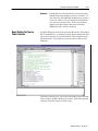
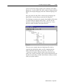
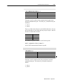
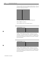
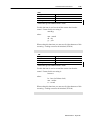
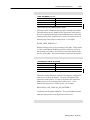
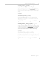
The Basic Display Set was developed using Microsoft’s Visual Basic
Pro development tool. Assuming you have already installed the OCI
source code, open the OCI project (ABOCI.VBP) using Microsoft’s
Visual Basic Pro. You should see a project window similar to the
following:
This project window gives you access to the display forms and code
used to compile the Basic Display Set screens. Each form typically
represents a specific 9/Series or 9/PC screen.
Publication 8520-6.6 - August 1999
3–6
OCI Basic Display Set (BDS)
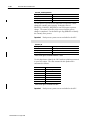
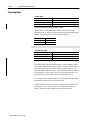
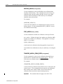
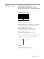
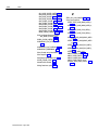
Basic Display Set Screen
Construction
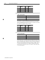
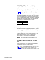
The majority of the 9/Series or 9/PC Basic Display Set screens are
laid out using a combination of overlaying forms. The forms used to
build a typical 9/Series or 9/PC screen include:
System Information
Display Form
Main MDI Form
PAL/Logic Messages Form
Softkey Area
• Main Form (MAINMDI.FRM) – This form provides the structure
for all the 9/Series or 9/PC screens (MDI parent form). It defines
the size and layout, initializes global variables, loads system
information form, PAL/Logic message form, and softkey form.
Other forms overlay this form to provide the proper display.
• System Form (SYSTEM.FRM) – This form overlays at the top of
the Basic Display Set screen. It is used to display system
messages and prompts for input information. It also manages
keyboard input. This form is loaded by MAINMDI.FRM.
• Display Form (screenname.FRM) – This form overlays the center
portion of MAINMDI.FRM. It is different and specific for each
9/Series or 9/PC screen to be displayed. The Program Position
Screen (PROGPOS.FRM) is an example of a display form. The
PROGPOS.FRM differs from other display forms in that it
remains loaded in background anytime the Basic Display Set is
running. This improves performance since this screen is the most
commonly used display form. Typically, display forms are
loaded and unloaded by the softkey modules.
Publication 8520-6.6 - August 1999
OCI Basic Display Set (BDS)
3–7
• PAL/Logic Messages (PALMSG.FRM) – This form resides just
below the display form and is used to display any messages sent
from the PAL/Logic to be displayed on lines 21 and 22 of the
BDS. This form is loaded by MAINMDI.FRM. Line 1
PAL/Logic messages are displayed on the SYSTEM.frm, Line
13–19 PAL/Logic messages are displayed on the
MESSAGES.frm.
• Softkey Form (SOFTKEYS.FRM) – This form resides at the
bottom of MAINMDI.FRM. It is used to handle softkey display
and loads and unloads display forms as needed. This form is
loaded by MAINMDI.FRM.
Basic Display Set
Basic Modules
In addition to the standard forms several basic modules can be found
in the ABOCI.VBP. The function of these basic modules is:
This Basic Module:
Is Used To:
GLOBAL.BAS
Manages general global data such as screen size,
font sizes, error handling and identifies general
information about the CNC connected to the OCI.
LANGUAGE.BAS
Manages transition between languages and
changes between the different text files for the
different languages.
OPT_NUMS.BAS
Defines constants used by the BDS to enforce
option PAL capabilities removing softkeys and
screens for features not supported on the system.
PD_NUMS.BAS
Defines constants used by the BDS to navigate the
softkey tree
PR_NUMS.BAS
Defines constants used by the BDS to refer to
prompt text strings.
SK_NUMS.BAS
Assigns text names to the softkey numbers returned
by the softkey module per row of softkeys.
SOFTKEYS.BAS
Uses a case statement to identify what action should
be taken when a specific softkey is pressed.
SR_NUMS.BAS
Assigns text names to the screen numbers returned
by the softkey module.
Publication 8520-6.6 - August 1999
3–8
OCI Basic Display Set (BDS)
Using MASTERM.FRM
Template to Create a
Display Form
Also include with the Basic Display Set source code are three forms
used as templates to create the majority of the other display forms in
this Visual Basic project. These forms are found with the rest of the
Basic Display Set forms in the FRM sub–directory of your Basic
Display Set source code. We call these “master” forms. They are:
• MASTER.FRM – a highly comment form typically used for
reference only when building other forms.
• MASTER0.FRM – use to build forms with no cursor movement
• MASTERM.FRM – use to build forms that require cursor
movement
The following section will walk you through the development of a
screen using a MASTER.FRM.
Making a Copy of MASTER.FRM
Since the master forms are a good place to start for creating any
additional screens in the Basic Display Set, it is probably a good idea
to use a copy of these forms instead of editing them directly. This
will always give you a clean starting point for any additional forms
you need to create.
Publication 8520-6.6 - August 1999
OCI Basic Display Set (BDS)
3–9
To make a copy of the MASTER.FRM:
1. Open a dummy Visual Basic project. The default “Project1” is
acceptable.
2. Under the Visual Basic “File” menu select “Add File”. Browse
to your Basic Display set source code directory and select the
master.frm you wish to use for your new screen.
3. From the project window open the form and press F4 to bring up
the properties sheet.
4. On the properties form change the “Name” field for the form to
something other than one already used in the OCI Basic Display
Set source code (this name should be descriptive of what you plan
to use this form for). You may also choose to change the
“Caption” field at this time as well.
5. From the “File” menu select “Save File As”.
6. Type in a new file name for the form in the Save As dialog box
and select save. This must also be a unique file name not already
used in the Basic Display Set source code.
7. From the “File” menu select “Open Project”. Visual Basic will
prompt you to “Save Changes to ...”. Assuming you already
saved the file from step 5., you should be able to select “No to
All” on this dialog.
8. Open the Basic Display Set Visual Basic source project
(ABOCI.VBP). You should find this file in the directory you
specified when you installed the Basic Display Set source code.
9. Under the Visual Basic “File” menu select “Add File”. Select
the form name you saved in step 6.
This will add your copy of the master form to the Basic Display Set
source project while keeping the original master form intact.
Publication 8520-6.6 - August 1999
3–10
OCI Basic Display Set (BDS)
MASTER.FRM Recommended Subroutines
When you develop your new screen we recommend you use the
following subroutines to properly integrate your form into the Basic
Display Set.
Publication 8520-6.6 - August 1999
Use this Subroutine:
Description:
APromptPressed (public)
Keyboard input is passed from the system form to
this subroutine. Use APromptPressed to identify
what actions should be taken when the user presses
a keyboard key. This routine receives the KeyCode
and Shift status from the system form
(FormKeyPressed).
ASoftkeyPressed (public)
Softkey inputs are passed from the softkey form to
this subroutine. Use ASoftkeyPressed to identify
what actions should be taken when the user presses
a softkey. This routine receives the softkey index (0
- 6) as variable SoftkeyChoice). Note softkey
management (changing of levels and softkey
names) is handled by the softkey form. Use this
index in this form only to identify what actions your
form should take.
Form_Activate (private)
Use this code to perform activities after the form is
loaded. This routine sets focus to the system form
to monitor keyboard inputs after a new form is
loaded. Most forms Activate module has the line
fmSystem setFocus".
Form_Unload (private)
This software module is typically used to shut off any
automatic data links to the CNC as well as set the
current form to whatever form should be shown
when your form is unloaded.
InitForm (private)
Most of the Basic Display Set forms make use of this
routine to position labels (based on MDI location)
and other assorted initialization parameters.
CreateDataLinks (private)
This module is used to create any necessary DDE
links to the CNC to load your form.
DisplayRows (private)
This module is used to format the data on the
display. It is typically called from the module
lnkdata_change and handles how data is presented
on the form.
InitformLevelVariables
This module is used to initialize all the form level
variables on a Form_Load event.
OCI Basic Display Set (BDS)
3–11
Managing Errors on your Form
When you develop your new screen we recommend you place in
your code the following routine we use to handle and report error
conditions.
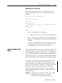
On Error GoTo ProgramError
(add your code here)
Exit Sub
Program Error:
WriteErrors string , Err, debug, errorFile
Resume Next
End Sub
Where:
string – is the message you want displayed
Err – indicates to the code it is an error (enter the string ERR)
debug – is the string you want to pass on to help debug the error
condition. We recommend you use the name of the form and its
sub name.
errorFile – the number of the file to write errors into. #1 writes
to the poking error files, #2 writes to to the linking error file.
See Writing to Error files utility later in this section.
Using the Softkey Editor
Utility
Also included with this source code is the softkey editor utility. Use
this utility whenever you need to add, remove, rename, or replace a
softkey in the Basic Display Set softkey structure. Though possible,
it is not recommended that you attempt to edit the softkey structure
without using this utility. You must have installed the Basic Display
Set source code before you will be allowed to use the softkey editor.
Each softkey in the Basic Display Set is assigned a number. Each
rack of five softkeys plus the more and back arrow keys is also
assigned a number. These numbers are used by the Basic Display
Set source code to determine if a softkey is to be displayed and what
forms appear when a specific softkey is pressed. Text for the
softkeys are stored in the data files with the extension .ABL and
.ABG. Aliases for the softkey numbers are created in the basic file
SOFTKEYS.BAS.
Important:
Any softkeys you add must be softkey 1500 or higher.
Softkeys 1 to 1499 are used or reserved by
Allen–Bradley for future product development.
Publication 8520-6.6 - August 1999
3–12
OCI Basic Display Set (BDS)
This procedure assumes you already have Visual Basic active with
the source file ABOCI.VBP open. To use the softkey editor utility:
1. Access the search utilities from the “Setup” menu in the Basic
Display Set. The “Setup” menu is only available when the source
code is loaded in the same directory as the Basic Display Set and
the variable SETUPMenu is set to True. Set this variable by
either:
• Manually change the variable in source code
(SETUPMenu is found in Global.Bas InitGlobals) or
• Manually change the variable FINAL_EXE to False
2. From the Visual Basic Run menu select “START”. The source
code should load and begin running. You should have the OCI
workstation connected to an OCI compatible CNC and the OCI
data server active or have your 9/PC running via the 9/PC
Configuration Manager. If the Basic Display Set can not find the
default CNC you have selected you will be prompted to select
another CNC to connect.
You should see the power turn–on screen. Pressing [Enter]
should display the program position display.
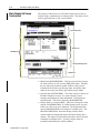
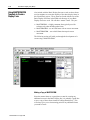
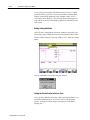
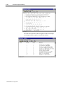
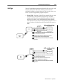
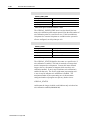
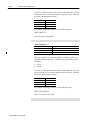
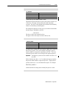
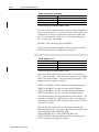
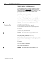
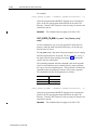
3. From the executing screen Setup menu, select “Softkeys”.
The basic displays should show the softkey edit tools after
loading the text files for all valid languages. The softkey edit
tools are shown in the following figure.
Publication 8520-6.6 - August 1999
OCI Basic Display Set (BDS)
Current Softkey Row (SPD_Ptr)
Softkey row number called
when up arrow is pressed
3–13
Current Softkey Number
Edit Softkey Text (buttons 1 thru 5)
Toggles between showing
softkey row numbers
(when K is visible) and
screen number (when S
is visible)
Create New Softkey Pointer (buttons 1 thru 6)
The softkey row pointer called when that softkey is pressed (K)
or the screen pointer called when that softkey is pressed (S)
Softkey row number called
when right arrow is pressed
Current Softkey Row (SPD_PTR)
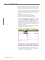
When you first load the softkey editor you will notice that the
number on the far left (where the up arrow would normally be) is 18.
This number indicates the current softkey row number. So anytime
softkey row 18 is called the softkeys {PRGRAM MANAG}, {OFFSET},
{MACROPARAM}, etc... are displayed.
Softkey Row Number Called
The number in the white box below where the up arrow should be
currently shows a zero. This number indicates the row number
called when the up arrow is pressed. Since this is the first level of
softkeys this box is white and zero indicates no new softkey row is
called.
Current Softkey Number
The current softkey number appears on top of the right arrow. This
field is not changeable however, since this value is referenced
throughout the Basic Display Set, it is provided on this screen.
Edit Softkey Text Buttons
The five buttons on the softkey names are used to change the text for
a softkey
K/S Button
Initially this button is set to K, which indicates the pointer field
beneath the softkeys is showing the softkey key numbers. Pressing
this button again changes it to S, which indicates the pointer field
shows the screen number.
Softkey and Screen Pointer
This field contains either the number of the softkey row (S mode) or
the screen number (K mode) called when that softkey is pressed.
Publication 8520-6.6 - August 1999
3–14
OCI Basic Display Set (BDS)
Create New Softkey Pointer Buttons
The 6 buttons to the right of the softkey and screen pointer are used
to create a new softkey with a new softkey pointer and screen pointer
if desired.
The softkey tree can be navigated as usual, change rows or levels
using the function keys or mouse as you would normally.
Important:
Though the softkey tree appears to be functional, the
tree will not call different forms or perform any of the
functions usually available with the softkeys when in
the softkey edit mode.
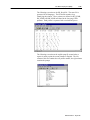
Changing Softkey Text
To edit the text for any softkey click on the appropriate “Edit Softkey
Text” button (button shown just to the right of the softkey text you
wish to change). An “Enter Text” window opens up showing the
current text for that softkey in all languages available on that system.
Edit Softkey Text (buttons 1 thru 5)
Softkey text can not contain more then 12 characters including any
spaces. The first six characters entered go on the first line of the
softkey, use spaces to move any text to the second line.
Publication 8520-6.6 - August 1999
OCI Basic Display Set (BDS)
3–15
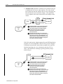
Changing the Softkey Row Pointer
To edit or change the set of softkeys called when a softkey is pressed
edit the softkey row pointer. The softkey row pointer is located in
the white or yellow box beneath the softkey text.
Softkey Row Pointers (fields 1 thru 7)
Must be in Key
Edit Mode (K)
When the softkey pointer field is yellow, it indicates that pressing
this key will display another softkey row. When the softkey pointer
field is white, it indicates that pressing this key does not call another
softkey row. The number in a white softkey row pointer is the
softkey number. A new form may be loaded for any softkey pressed
regardless of if another softkey row is called. See “Inserting a New
Screen” on page 3–17 for details on identifying a screen pointer.
To change the next row of softkeys called by pressing a softkey, edit
the “Softkey Row Number ” field. You can change this field for the
five softkeys as well as the up arrow (back) and right arrow (more)
softkeys.
Publication 8520-6.6 - August 1999
3–16
OCI Basic Display Set (BDS)
Creating/Editing a Softkey
1. To create a new or change the operation of an existing softkey
press the “Create New Softkey Pointer” button.
Must be in Key
Edit Mode (K)
Create New Softkey Pointer (buttons 1 thru 6)
2. If you haven’t already entered text for this new softkey you are
prompted for text for the softkey in the available languages.
Each of the text fields in the above screen writes data to a
different softkey data file for each language. The softkeys toggle
through different languages each time the {SWITCH LANG}
softkey is pressed. After entering language text for your softkey
in the appropriate languages press the OK button.
3. The softkey editor prompts you to add a Key or a Row.
Key – select “KEY” if you are entering a softkey only that will
not call another row of softkeys. Note this key can still call a new
screen.
Row – select “ROW” if you are entering a softkey that is to call a
new (or existing) row of softkeys.
Publication 8520-6.6 - August 1999
OCI Basic Display Set (BDS)
3–17
4. After deciding if you are entering a key or row you are prompted
to add a screen number. If this softkey is to call a new form you
should select “Yes”.
Inserting a New Screen
Screens for the Basic Display Set are called by softkey events.
When you add a new softkey using the softkey editor (Create New
Softkey Pointer) you are prompted to add a screen number as shown
above.
When you select yes to add the softkey screen number the source
code adds a screen pointer to the softkey structure. Note the screen
pointer added is always the same number as the softkey pointer (see
page 3–17 for details on screen pointers).
To edit, view, or change the screen pointer for a softkey, view the
screen pointer by clicking on the K button to toggle it to S (screen
mode). Change the pointer manually as discussed in the next
section.
Creating/Editing the Screen Pointer
To change the screen number called when a softkey is pressed, edit
the “Screen Pointer Number” field while in the softkey editor. You
can change this field for the five softkeys. You can not change the
screen number displayed when the up arrow (back) or right arrow
(more) softkeys are pressed.
Must be in Screen
Edit Mode (S)
Screen Pointer Number Fields (buttons 1 thru 5)
Important:
Edits to this field are typically only necessary when
changing the field for an existing softkey. If you are
adding a new softkey to call a screen follow the
directions for adding a softkey on page 3–16 and you
will be prompted if you want the system to add the
screen number automatically.
Publication 8520-6.6 - August 1999
3–18
OCI Basic Display Set (BDS)
A zero in the screen pointer field indicates that no screen is called
when that softkey is pressed. New screen numbers added to Basic
Display Set should be numbered 1501 or higher (below 1501 is
reserved by Allen–Bradley). This will help protect the integrity of
your edits if any future Allen Bradley updates are installed on your
OCI system.
Exiting Softkey Edit Mode
After you have completed the necessary changes to the softkey tree
and screen pointers added you must save and exit the softkey editor.
Exit the softkey editor by selecting “Softkey Tree” under the “Setup”
menu.
You are prompted to save or discard your changes.
Calling the Screen Pointer in Source Code
Once you have added the necessary softkey and screen pointers you
must make modifications to your source code to call the proper
screens. Screens are called using two subroutines of the Basic
Display Set:
Publication 8520-6.6 - August 1999
OCI Basic Display Set (BDS)
3–19
SetSPDPointer
You should not need to edit this file unless there are special
conditions you wish to apply to determine when and what screen is
loaded when a softkey is pressed. For example you may want to
add a condition that prohibits access to a servo configuration screen
when running a program.
SetSPDPointer is a routine found in the file SOFTKEY.BAS. This
subroutine uses the softkeys PD Number (PD_PTR) to determine
which softkey choice was made and sets the variable
“ScreenNumber” using a series of Case statements.
The Case Else statement at the end of this routine sets the variable
ScreenNumber = PD (PD_PTR).ScreenNum. The variable
ScreenNum is the screen number pointer assigned in the softkey tree
(see page 3–17) so by default this routine loads the assigned screen
number to the variable ScreenNumber whenever the softkey is
pressed. PD_PTR numbers are assigned in the file
PD_NUMS.BAS.
LoadScreenForm
This subroutine ,found in the file Softkey.BAS, is used to load the
final form. This routine uses the “ScreenNumber” variable assigned
in SetSPDPointer to determine what screen should be loaded. A
series of Case statements are used to define two variables which load
the appropriate form, CurrentForm (a form), and CurrentFormName
(a string).
Identify screen numbers with their corresponding screen names in
the file SR_NUMS.BAS. Any new screen numbers you are adding
should be defined in this file.
Publication 8520-6.6 - August 1999
3–20
OCI Basic Display Set (BDS)
Using the Text Find Utility
To improve flexibility of our source code, screen text and prompts
are not directly entered on any screens. Instead they are entered in
different language text files and each screen calls the required piece
of text from the appropriate file by a pointer when needed.
Unfortunately this can make it difficult to identify exactly what text
is to be displayed on what screen when writing code since only a file
pointer is available on the screen.
The Basic Display Set source code has a search utility which allows
you to change text or prompts on any of the standard 9/Series screens
as well as identify the text pointer numbers.
Important:
These search utilities do not apply to text found on the
9/Series or 9/PC editor, any ODS screens including the
PAL search monitor screens. These screens can not be
edited and are not part of the Basic Display Set source
code.
Access the search utilities from the “Setup” menu in the Basic
Display Set. The “Setup” menu is only available when the source
code is loaded in the same directory as the Basic Display Set and the
variable SETUPMenu is set to True. Set this variable by:
• Manually change the variable in source code
(found in Global.Bas InitGlobals) or in
SetupGlobalVarsforNewCNC) or
• Manually change the variable FINAL_EXE to False
You can search for either prompts or text:
Prompt Search – If you select “Prompt” search from the setup menu
you will be searching for prompts (such as MDI: or CHANGE
VALUE:). Prompts are text strings used to request an operator input
of some type.
Text Search – If you select “Text” search from the setup menu you
will be searching for text used to build the standard screens (such as
ACTIVE PROGRAM or MEMORY).
After you have selected your search type the softkeys are removed
from the screen and replaced with the following search dialog:
Publication 8520-6.6 - August 1999
OCI Basic Display Set (BDS)
Entry Box for Search String
3–21
Entry Box for Pointer Number
(PR_NUMS.bas for prompts
text file string number for text)
Maximum characters that can be inserted when
responding to this prompt (Prompts Only)
Edit last found search string
Create new text and pointer
Last Found Search String
Enter either a pointer number, text, or prompt string in the
appropriate box. Pressing the enter key performs the search. If you
enter a string to search for, the pointer number for the found string
appears in the # box. Wildcard characters (*) are invalid. The
search string function automatically inserts wild cards before and
after the entered search string (for example entering a search string
“A” will find all strings that contain the letter A). The found text
for the search operation is displayed in the last found search string
field.
Press the “EDIT” button to change the text for an already found
pointer number. Press the “NEW” button to add a new text pointer
with a new text string to the language files.
Exiting the Text Search Utility
After you have completed the necessary changes to the text and
prompt files you must save and exit the utility.
Exit the text or prompt search utility by selecting “Text” or “Prompt”
under the “Setup” menu. You will be prompted to save your
changes.
Publication 8520-6.6 - August 1999
3–22
OCI Basic Display Set (BDS)
Using the Print Utilities
The Basic Display Set provides a print utility to help you document
your application. This utility writes the requested data to a file for
printing or use in a spread sheet. The following items can be printed
to a file:
•
•
•
•
•
•
Error Messages – writes all error messages to an ASCII file.
Prompts – writes all screen prompts to an ASCII file.
Softkey Tree – writes all softkey text to an ASCII file.
Text – writes all miscellaneous screen text to an ASCII file.
PD_Ptr’s – writes all softkey pointers to an ASCII file.
SPD_Ptr’s – writes all screen pointers to an ASCII file.
Access the print utilities from the “File” menu in the Basic Display
Set. The “Print” option under the File menu is only available when
the source code is loaded in the same directory as the Basic Display
Set and the variable PRINTMenu is set to True. Set this variable by:
• Manually change the variable in source code
(PRINTMenu is found in Global.Bas InitGlobals or in
SetupGlobalVarsforNEWCNC) or
• Manually change the variable FINAL_EXE to False
When you select the desired print option the Basic Display Set
creates, or overwrites if the file already exists, a data file containing
the text, corresponding pointer number, and other relevant
information. File naming convention is as follows:
File Extension
Language
File Name
Error MSG
Prompts
Softkey
Tree
Text
SPD_Ptr's
.err
.pmp
.sft
.stx
.spd
English
English
German
Deutsch
French
Francais
Italian
Italian
Spanish
Espanol
Publication 8520-6.6 - August 1999
OCI Basic Display Set (BDS)
3–23
A file is created only for the currently active language on the Basic
Display Set. Use the {SWITCH LANG} softkey to change the Basic
Display Sets displayed language and create different language print
files.
Since the pointer file PD_PTR’s is identical for all languages the
print PD_Ptr’s selection always creates the file PD_ptr.pd.
The following screen shows an example of the English.sft file which
is compiled from the English softkey tables. This file uses tab
characters to indicate different levels of the softkey tree. It also
shows the softkey number to the right of the text.
This next screen example shows the English.spd file which is
compiled from the English softkey text file combined with the
pointer information and softkey tree structure. This file uses
“?”characters to separate different softkey names from the same
softkey rack. Below each softkey rack is pointer information for the
first thru seventh softkey (includes back and more softkeys) and the
softkey text pointer number.
Publication 8520-6.6 - August 1999
3–24
OCI Basic Display Set (BDS)
The error text file shown in the next figure lists the error message
text strings and their respective error pointer numbers.
Publication 8520-6.6 - August 1999
OCI Basic Display Set (BDS)
3–25
The following screen shows the PD_Ptr.pd file. The same file is
generated for all languages. The file header contains a key
identifying the pointers. These pointers are defined in SK_NUMS,
PR_NUMS, and SR_NUMS and found in the (language).SPD
printouts. Each pointer is separated with a comma and spaces.
The following screen shows the english.pmp file created when a
request is made to print the screen prompts in English. The left
column of this file contains the text pointer number, the right column
contains the prompt.
Publication 8520-6.6 - August 1999
3–26
OCI Basic Display Set (BDS)
The following screen shows the english.stx file created when a
request is made to print the screen text in English. The left column
of this file contains the text pointer number, the right column
contains the screen text.
Testing and
Debugging Utilities
The Basic Display Set has built in testing and debugging utilities that
can simplify diagnosing problems with your modifications. There
are two different utilities provided:
• Debugging – when this utility is enabled extensive error messages
appear in a MsgBox reporting detailed information on coding
errors.
• Write to File – this utility writes program errors, data linking
errors, and data poke errors to their respective files.
Debugging Utility
The debugging utility enables a Message box which identifies errors.
The Debugging utility is only available when the source code is
loaded in the same directory as the Basic Display Set and the
variable DEBUGGING is set to True. Set this variable by one of
these methods:
• Manually change the variable in source code
(DEBUGGING is found in Global.Bas InitGlobals) or
• Manually change the variable FINAL_EXE to False
Publication 8520-6.6 - August 1999
OCI Basic Display Set (BDS)
3–27
Write to Error File Utility
This utility writes program errors, data linking errors, and data poke
errors to their respective files. When this utility is enabled it creates
the following files:
File Name:
Registers these type of errors:
ABVBPOKE.ERR
Data poking errors from the Basic Display Set source code
that uses the CNCPoke sub call. This file is referenced as
error file number 1 in source code.
ABVBPRGM.ERR
Linking errors from all CreateDataLinks routines and other
program errors encountered in the Basic Display Set. This file
is referenced as error file number 2 in source code.
The write to error file utility is only available when the source code
is loaded in the same directory as the Basic Display Set and the
variable WRITE2ERRORFILE is set to True. Set this variable by
one of these methods:
• Manually change the variable in source code
(WRITE2ERRORFILE is found in Global.Bas InitGlobals)
• Manually change the variable FINAL_EXE to False
Publication 8520-6.6 - August 1999
Chapter
4
OCI Data Server Data Items
Data Item Format
Each OCI data item is presented in the following format:
Data Item
Description
Data Type
Indicates the format the data item will be presented
to the OCI data server. Refer to page 4-2 for
details.
Read/Write
R indicates the data is read only (passed from CNC).
R/W indicates the data is both read and write. Refer
to page 4-2 for details
Array Index
Indicates the index in an array, none indicates data
can not be accessed as an array. Refer to
page 4-3 for details.
CNC Type
Indicates the type of CNC that uses the data item.
For example lathe/mill/grinder etc. Refer to
page 4-8 for details.
Other important information that may be included with data items is:
• Link Type – None, Automatic, Notify, Manual. The link type is
application selectable. Refer to page 4–9 for details.
• Background/Foreground – All data items are monitored in the
controls background unless otherwise indicated in the text
describing the data item. All foreground data items are discussed
in this chapter. Refer to page 4–13 for details.
• Dual Process – Follow the data item with a .1 or .2 to indicate the
process number. No process number by default makes a request
for process 1. Single process systems can also use .1 as a valid
data item request. Use the table in appendix A to determine if an
item is available as dual process. For example:
PROCESS_NAMES.1
would return the text string used to identify the process 1 name.
Important:
Currently, process options do not apply to the 9/PC
CNC.
• The value returned by many data items (especially axis position
information) is not always rounded by the systems configured
basic positional resolution. If your application requires rounded
display information you must perform the rounding in your
applications code. For example you may see an axis position as
–0.5 on the position display but axis calibration items may see
this position as –0.499999980314961.
Publication 8520-6.6 - August 1999
4–2
OCI Data Server Data Items
Data Type
Read/Write
The data type for a OCI data item determines how the data is
returned from the control to the OCI. You define variables according
to this data type. Requesting the wrong data type for a data item to
the control can return invalid data or an error. Valid data types
include:
DATA TYPE:
Description:
STRING
Alphanumeric string ranging from 0 to 65,535 characters
INT
Whole number ranging from -32,768 to 32,767
UINT
Unsigned integer
DINT
Double integer
UDINT
Unsigned double integer
LINT
Long Integer
SINT
Signed integer
USINT
Unsigned single integer
REAL
Real number
LREAL
Long Real
BOOL
Boolean (True/False)
R indicates the data is read only (passed from CNC to OCI). W
indicates the data is write only (passed from the OCI to the CNC).
R/W indicates the data is both read and write. Errors are generated if
you attempt to write data to a read only OCI data item.
Write privileges for commands and API data items are reserved for
the controlling OCI station. You must first successfully issue the
REQUEST_CONTROL command before write requests will be
accepted by the OCI station. Refer to the command chapter for
details on issuing the REQUEST_CONTROL command.
Publication 8520-6.6 - August 1999
OCI Data Server Data Items
Array Indexes
4–3
Some OCI data items are accessed as arrays. The format for the
majority of these arrays can be broken down into just a few array
indexes. The array index is called out with each data item. The
following presents the format for the most common arrayed data.
This is not an inclusive list. Other less frequently used array indexes
are used and described with the data items or commands that use
them.
Array Index:
Description:
AXIS_NUM
AMP configured axis number
SPINDLE_NUM
AMP configured spindle number (1 to 3)
configured spindle number for 9/PC (1 to 2)
CNC_DIRECTORIES
1 (the main directory), 2 (the protectable directory or
3 (the PC local OCI file handler directory typically the
Pc's hard disk).
SERVO_MODULES
the servo module number on the system (1 to 3) 1
SERVO_NUM
AMP configured number of the servo on your system
M_MODAL_GROUP
the modal group of a M code
G_MODAL_GROUP
the modal group of a G code
SETUP_BUFFERS
the active number of part program setup buffers
NUM_PP_FILES
the number of part programs currently in the
directory
OFFSET_NUM
the tool offset number
1 Always
= 1 on 9/PC
Many of the data items are two dimensional arrays and would thus
have two array indexes associated with them. For example the data
item TOOL_LENGTH_WEAR_OFFSETS is a two dimensional
array using the indexes OFFSET_NUM and AXIS_NUM to define
its boundaries. Making the following data request of the server:
TOOL_LENGTH_WEAR_OFFSETS,2,3
requests the tool length wear offset number 2 for axis number 3.
Unless otherwise mentioned in the argument description, most data
items allow the omission of indexes which returns all data in that
array. For items that use two or more arguments, only the right most
argument can be omitted if it is valid to omit arguments. Data
returned from an array is delaminated by Tab characters and ended
with a return/line feed character.
Publication 8520-6.6 - August 1999
4–4
OCI Data Server Data Items
AXIS_NUM
This array index is dimensioned by the axes number as configured
on the system in AMP. For example the data item AXIS_NAME,
which returns the name of the axes from the CNC, is an array based
on Axes_Number. So calling the data item:
AXIS_NAME,2
returns the text string axis name for the second axis. Calling the data
item:
AXIS_NAME,2–4
calls the text string for the axis names 2, 3, and 4. The values are
separated by a | (or tab) character.
SPINDLE_NUM
This array index is dimensioned by the spindle number as configured
on the system in AMP. The 9/PC CNC supports 2 spindles. Some
9/Series systems can support up to 3 spindles so this dimension
ranges from 1 to 3 spindles. For example the data item
SPIN_SPD_VALUE, which returns the active programmed spindle
speed for a specified spindle, uses this array index to determine
which spindle speed you are requesting.
SPIN_SPD_VALUE,2
returns the LREAL value representing the active spindle speed for
spindle number 2.
SPIN_SPD_VALUE,2–3
returns the LREAL values representing the active spindle speed for
spindle number 2 and 3. The returned values are separated by a |
(tab) character.
NUM_CNC_DIRECTORIES
This array index is dimensioned by the three available CNC part
program directories. They are:
1 – Main Program Directory
2 – Protectable Program Directory
3 – OCI File Handler Configured Directory (local to PC)
Publication 8520-6.6 - August 1999
OCI Data Server Data Items
4–5
For example the data item NUM_FILES, which returns the number
of part programs that exist in a specific directory, uses this array
index to determine which directory you are requesting information.
NUM_FILES,2
returns the UINT value representing the number of part programs
currently residing in the protected part program directory. You can
not request information from multiple directories with the same
command. This argument can not be omitted from items that use the
CNC_DIRECTORIES argument.
SERVO_MODULES
This array index is dimensioned by the number of servo modules
available on your 9/Series. The array index always returns “1” on a
9/PC CNC. The 9/260 and 9/290 CNCs can have up to three servo
modules installed. This array index ranges from
1 to 3.
For example the data item SERVO_FW_REVISION returns the
firmware revision number for the servo control on the 9/PC card.
This item does not return revision of the servo software on the 1394
CNC serial drive. The data item uses this array index to determine
which servo module you are referencing.
SERVO_FW_REVISION,2
returns the DINT value representing the firmware revision number
for the second servo module on a 9/260 or 9/290. Refer to the
SERVO_FW_REV item description for details on the return value
format for this item.
SERVO_NUM
This array index is dimensioned by the AMP configured number of a
specific servo port on the control. This is the logical servo number
including split, dual, spindles, and adaptive depth probes. This array
index ranges from 1 to 15.
For example the data item SERVO_NAME, which returns the name
of the servo as configured in AMP, uses this array index to determine
which servo you are referencing.
SERVO_NAME,6
returns the SINT value representing the axis name of the number six
axis configured in AMP.
Publication 8520-6.6 - August 1999
4–6
OCI Data Server Data Items
M_MODAL_GROUP
This array index is dimensioned by the valid M code modal groups.
M code modal groups range from 0 to 13. Refer to your operation
and programming manual for details on M codes and their respective
modal groups.
For example the data item M_CODE_STATUS, which returns the
active programmed M code number, uses this array index to
determine which modal group you are checking.
M_CODE_STATUS,4
returns:
If this Group 4
Mcode is Active:
Returned Value
M00
0
M01
1
M02
2
M30
30
G_MODAL_GROUP
This array index is dimensioned by the valid G code modal groups.
You can find the G code modal groups range in
NUM_G_GROUPS_1 (an API item). Refer to your operation and
programming manual for details on G codes and their respective
modal groups.
For example the data item G_CODE_STATUS, which returns the
active programmed G code number, uses this array index to
determine which modal group you are checking.
G_CODE_STATUS,4
returns:
Publication 8520-6.6 - August 1999
If this group 4
Gcode is Active:
Returned Value
G22
220
G22.1
221
G23
230
G23.1
231
OCI Data Server Data Items
4–7
SETUP_BUFFERS
This array index is dimensioned by the currently available part
program setup buffers. This number is dependent on several factors
including complexity of the current part program and number and
type of features active at any given time. This number will range
from a minimum of 1 to a maximum of 21.
For example the data item ACTIVE_PART_PROGRAM_BLOCKS,
which allows you to identify blocks that have been read into the
setup buffer uses this array index:
ACTIVE_PART_PROGRAM_BLOCKS,2
NUM_PP_FILES
This array index is dimensioned by the number of part programs
currently in the directory. Not to be confused with the part program
name (proceeded with the O word and often a number) this integer
value is the number in the directory of the program you want to
investigate. For example if the main directory has three part
programs in it:
O123456
DRVSHAFT
RRIGHT47
O123456 would be program one. DRVSHAFT would be program 2
and RRIGHT47 would be program 3. The maximum size of this
array index is dependent on the number of programs in the directory.
For example the data item FILE_NAME, which returns a string of
the part program name, uses this array index to determine which
program name you want. Note this data item also uses the
NUM_CNC_DIRECTORIES array index. Format is:
FILE_NAME, NUM_CNC_DIRECTORIES, NUM_PP_FILES
FILE_NAME,1,3
returns the STRING of “RRIGHT47” assuming RRIGHT47 is the
third program in the main part program directory.
Part programs are stored in alphabetical order in the CNC
directories.
Publication 8520-6.6 - August 1999
4–8
OCI Data Server Data Items
OFFSET_NUM
This array index is dimensioned in AMP as the maximum number of
tool offsets allowed on your system.
TOOL_NUM
This array index is dimensioned in AMP as the maximum number of
tool numbers allowed on your system.
Control Type
The “Control Type” attribute indicates the application(s) for which a
particular data item can be used: either:
• Mill,
• Lathe
• Grinder
Important:
1
1
Grinder type control is not available for Release 1 of
the 9/PC.
The entire dual processing system is not available for Release 1 of
the 9/PC CNC. The single processing system is available on both the
9/Series and the 9/PC CNC. Some data items are not available on
the dual processing system or are not available on the single
processing system. These are indicated as:
(dual-process only) or
(single-process only)
Other data items without this designation should be assumed
available on both single and dual-processing controls (dual process is
not available for Release 1 of the 9/PC).
The control type is determined by a combination of the executive
software supplied with the control and the AMP configured control
type.
Publication 8520-6.6 - August 1999
OCI Data Server Data Items
Link Type
4–9
Your OCI application program must choose the link type to be used
based on your specific data needs. When you create an OCI
application program, you must choose the link type that meets your
needs. If your OCI application program requests a:
• Manual Link. Data that is identified as a manual link type must
be requested by your application program to get an update.
Changes to the data are not automatically updated on the OCI
station by the control. Your application must request that the
control update the OCI station. The application program receives
only one update of the data from the control when the request is
made.
OCI
Server
RSLinx
9/Series
CNC
2
●
2
●
1
●
DDE Application
3
●
1 The DDE Application requests the current data value for an
●
item contained in the OCI Server.
The
Server reads the current value from the processor
2
●
containing the item data point through RSLinx.
3 The Server sends the current value of the item to the DDE
●
2 Application.
OCI
Server
9/PC
CNC
9/Series Manual Link
9/PC only Manual Link
1
●
DDE Application
3
●
1 The DDE Application requests the current data value for an
●
item contained in the OCI Server.
22 The Server reads the current value from the 9/PC
●
processor containing the item data point.
3 The Server sends the current value of the item to the DDE
●
2 Application.
Publication 8520-6.6 - August 1999
4–10
OCI Data Server Data Items
• Automatic Link. Data that is identified as an automatic link type
is added by the OCI server to the watch list. The value for the
item is then sent from the control to the OCI server and again any
time the data item on the watch list changes. Your application
receives updates to the items each time the value changes on the
control.
OCI
Server
RSLinx
9/Series
CNC
2
●
3
●
9/Series Automatic Link
1
●
DDE Application
1 The DDE application requests an automatic data item
●
from the OCI server. The data server requests the
control add the data item to the 9/Series watch list.
2 The CNC adds the data item to the watch list
●
and sends the current value of the data item
back to the OCI server.
The 9/Series sends the value to the OCI data server
3
●
whenever the item value changes. The OCI server then
passes the new value on to the DDE Application. The
9/Series continues to update the OCI data server every
time the value of the data item changes as long as the
item remains in the 9/Series watchlist.
Notify link mode option, though supported by most DDE application
programs, are not recommended. Since the OCI system is designed
to minimize network traffic, notify links are added to the watch list
instead of requiring your server continuously pole the CNC for
status. This nullifies the advantages typically gained by using a
notify link type.
9/PC Automatic Link
OCI
Server
3
●
9/PC
CNC
2
●
1
●
DDE Application
1 The DDE application requests an automatic data item
●
from the OCI server. The data server requests the
control add the data item to the 9/PC watch list.
2 The CNC adds the data item to the watch list
●
and sends the current value of the data item
back to the OCI server.
The 9/PC sends the value to the OCI data server
3
●
whenever the item value changes. The OCI server then
passes the new value on to the DDE Application. The
9/PC continues to update the OCI data server every
time the value of the data item changes as long as the
item remains in the 9/PC watchlist.
Publication 8520-6.6 - August 1999
OCI Data Server Data Items
4–11
The OCI WatchList
Once your DDE application makes a DDE request to the OCI data
server, the data item is added to a watchlist maintained by the CNC.
New items are added and old items are removed from the watch list
as requested by the OCI data server. Once the CNC has a watch list
it monitors the specified items in the list for changes. When a
change occurs to a piece of data, the processor (after waiting a
configurable number of coarse iterations) sends the OCI data server
the new information.
If multiple OCI data servers are running on the network, there can be
multiple watch lists on any one control. The 9/Series control is
capable of maintaining multiple watch lists (up to 4 different OCI
stations) and will return data as needed to the appropriate OCI
station. The 9/PC can maintain watchlists for only one data server.
Since the watchlist is maintained on the control’s processor instead
of on the workstation (as is common with more typical DDE
applications) the OCI shows improved network performance over
similar competition by not requiring continuous polling of data from
the workstation. It also prevents continuous transmission of
automatic data on the network as data is only transferred to the OCI
server when an item on the watchlist changes. This is the reason no
polling rate configuration is necessary for the OCI installation.
As more items are added to the watch list, more processing time is
required from the processor. We recommend keeping the watchlist
as small as possible to prevent performance degradation and out of
room on watchlist errors. Though most OCI applications make a
negligible change in performance you should not unnecessarily load
the system up with requests for data until that data item is actually
needed. The maximum combined number of data items that any
processor can maintain on all watch lists is based on what data items
are in the watch list as well as remaining control memory.
Important:
If your application uses RSJunctionBox (as used by the
Basic Display Set) you must include an item destroy
command in your logic. Item destroy is used to prevent
the WatchList from filling by maintaining links to data
items that are no longer needed. Refer to page 1–8 for
details on item destroy.
Important:
Refer to your AMP reference manual for details on
determining and configuring the OCI WatchList Buffer
Size.
Two watch lists are created on the CNC for every connected OCI
station. See the background/foreground section in this chapter for
details. Systems with extremely large watch lists may need to
increase their AMP configured system scan times.
Publication 8520-6.6 - August 1999
4–12
OCI Data Server Data Items
• POKE POKE operations are used to send data to the processor
from the OCI data server. The Server sends the value from your
application program to the processor that contains the data item.
ATTENTION: Extreme care must be taken when
using the POKE capability. If you inadvertently write
to critical data in the CNC, you could adversely affect
the operation of the CNC.
!
Monitor the status of POKE commands using the data item
WRITE_ERROR_CODE which will return the success or failure of
a POKE operation as discussed in the error appendix later in this
manual.
Important:
To perform a poke operation, the OCI station making
the request must be the controlling station. Refer to the
API command items “REQUEST_CONTROL” and
“RELINQUISH_CONTROL”.
OCI
Server
RSLinx
9/Series Poke
1
●
DDE Application
2
●
9/Series
CNC
1 The DDE Application sends a value to the
●
OCI Server for a data item.
2 The Server sends the new value to the
●
processor containing the data item via RSLinx.
OCI
Server
9/PC Poke
1
●
DDE Application
2
●
9/PC
CNC
Publication 8520-6.6 - August 1999
1 The DDE Application sends a value to the
●
OCI Server for a data item.
2 The Server sends the new value to the
●
processor containing the data item.
OCI Data Server Data Items
Background/Foreground
4–13
All data items are monitored in the controls background unless
otherwise indicated in the text describing the data item. Foreground
and Background speed is related to the system scan time. The
system scan time for the control is set in AMP. You can set the
system scan time in increments of 2 ms from 6 to 30 ms.
Foreground tasks occur during each system scan time. Data items
are hard coded in the processor as foreground or background. Only
the following data items are foreground items:
• ESTOP_STATE
• Select PAL/Logic system flags (ones that are foreground only)
The rate at which the CNC tests and reports data changes for OCI
watchlists is configured in AMP. Refer to your AMP Reference
Manual for details.
Background tasks are executed whenever there is excess time
available during a system scan time. The execution continues only
as long as there is excess time. When the excess time is used up, the
current background task is marked and foreground PAL/Logic
execution begins. Background execution resumes at the marked
position when there is excess time available again during future
coarse iterations.
Important:
Since background tasks may be updated at various
intervals of the control cycle, it is necessary to
coordinate I/O or other PAL/Logic variables with
system timing. For the 9/PC, no I/O variables exist and
the only access is through system flags. For the
9/Series only, any values that change in foreground and
are accessed by the OCI (at a later time time in a
background scan) should be saved to a global variable
before the I/O value changes due to another change of
the variable in foreground. Failing to do this can cause
foreground events to be missed by the OCI data server.
When the OCI data server creates watch lists on the CNC, it creates
two different watchlists; one for foreground data items, and one for
background data items. If multiple OCI data servers connect to the
same 9/Series CNC, each OCI data server creates a separate
foreground and background watch list.
Important:
Release 1 of the 9/PC can support only one data server.
Publication 8520-6.6 - August 1999
4–14
OCI Data Server Data Items
Selecting the Process for
Dual Process Controls
The 9/Series provides a dual process option which allows the use of
the 9/Series to control multiple processes. Many API data items and
commands present different data based on the process you are
looking at. Refer to appendix A and B to identify if your API data
item or command is available in two different process.
Important:
Dual process options are not available for Release 1 of
the 9/PC CNC.
To specify which process your API data request or command is
targeting you can append the process number to the data item or
command following a period. For example:
NUM_AXES.1
NUM_AXES.2
would request the number of axes in process 1 and process two
respectively.
The default for all per process commands and API items is always
process 1 so the API item:
NUM_AXES
on a dual process system returns only process 1 data.
If an item or command has an argument, follow the process number
with the argument. For example:
AXIS_NAME.2,2–3
would return the second and third axis names in process 2.
Publication 8520-6.6 - August 1999
OCI Data Server Data Items
Logical vs Physical Axes
4–15
All data items for axes are presented in the OCI API in “logical”
order with the exception of some AMP parameters which are defined
in physical axis terms. For example the data item
“DRILLING_AXIS_LOGICAL_BIT_PATTERN” is an example of a
axis data returned as a logical bit pattern.
Logical axis refers to the order that the axis are presented in the
process. For single process controls this is not much of an issue with
the exception of spindles and virtual axes which are always stored as
the last axes in the process.
Physical axis refers to the order in which the axes are created using
the ODS AMP tool and are independent of the process the axes are
assigned to.
Physical Axis
Number (order
AMPed)
Process
Assigned
Logical Axis
Process 1
Axis 1
X
Process 1
1
Axis 2
Y
Process 1
2
Axis 3
Z
Process 1
3
Axis 4
U
Shared
4
Axis 5
A
Process 2
Axis 6
B
Process 2
Axis 7
C
Process 1
Logical Axis
Process 2
1
2
3
5
If looking at process 1 data item:
“DRILLING_AXIS_LOGICAL_BIT_PATTERN.1” axis data would
be returned in the bit pattern as X, Y, Z, U, C in the first five bits.
and for process 2:
“DRILLING_AXIS_LOGICAL_BIT_PATTERN.2” axis data would
be returned in the bit pattern as U, A, B in the first three bits.
Important:
Only single process is available for Release 1 of 9/PC.
Publication 8520-6.6 - August 1999
4–16
OCI Data Server Data Items
AMP Parameter
Data Items
@parameter_num
Data Type
LREAL
Read/Write
Read/Write (patch AMP only) Read (others)
Array Index
none
Control Type
Lathe/Mill/Grinder1
1 Grinder Control Type is not available for Release 1 of 9/PC.
Follow the @ symbol with the AMP parameter number you want to
edit. Refer to your AMP reference manual for details on AMP
parameters and their respective QuickEdit numbers.
Before you can make write to AMP parameters you must first
execute a MODIFYING_AMP command request. When your
changes are complete execute an UPDATE_AMP command to close
the AMP file. After completing AMP changes with this data item
you must cycle power to the control for the change occur.
Exceptions to this are online AMP parameters that can be set real
time (such as servo motor integral and proportional gain values).
Online AMP parameters are provided as separate API data items,
found under their corresponding topic, later in this chapter or
appendix A.
Important:
Only patch AMP parameters are writable. Other AMP
parameters (except online AMP parameters) are read
only. Use the data item
AMP_PARAMETER_NUMBER to identify what
parameters are available patch AMP.
You should identify the data type for an AMP parameter before
attempting to write to the parameter (see
AMP_PARAMETER_DATA_TYPE).
AMP_PARAMETER_DATA_TYPE patchAMP_num
Data Type
USINT
Read/Write
Read
Array Index
patchAMP_num
Control Type
Lathe/Mill/Grinder1
1 Grinder Control Type is not available for Release 1 of 9/PC.
This data item is used to identify the data type (format) for AMP
parameters that can be accessed using the patch AMP feature. The
patchAMP_num argument is the number of the patch AMP
parameter to identify, not the quick edit number or parameter number
(see AMP_PARAMETER_NUMBER). The
AMP_PARAMETER_DATA_TYPE item returns an enumeration
identifying the data type as follows:
Publication 8520-6.6 - August 1999
OCI Data Server Data Items
Enumeration
Result:
0
Short
1
Unsigned Short
2
Long
3
Unsigned Long
4
Quad
5
Unsigned Quad
6
Float
7
Double
8
Unsigned Character
9
ASCII Character
4–17
For example:
AMP_PARAMETER_DATA_TYPE,1
returns the data type enumeration for patch AMP parameter number
1. Use AMP_PARAMETER_NUMBER to identify the actual AMP
parameter associated with patch AMP parameter number 1.
AMP_PARAMETER_NUMBER patchAMP_num
Data Type
UINT
Read/Write
Read
Array Index
patchAMP_num
Control Type
Lathe/Mill/Grinder1
1 Grinder Control Type is not available for Release 1 of 9/PC.
This data item is used to identify quick edit number of a specific
patchAMP parameter. For example:
AMP_PARAMETER_NUMBER, 1
returns the value 11 indicating that AMP parameter with the quick
edit number of 11 is the first patch AMP parameter.
NUM_PATCHABLE_AMP_PARAMETERS
Data Type
UINT
Read/Write
Read
Array Index
patchAMP_num
Control Type
Lathe/Mill/Grinder1
1 Grinder Control Type is not available for Release 1 of 9/PC.
This data item is used to identify the quantity of available AMP
parameters that can be changed thru patch AMP. For example if the
value of NUM_PATCHABLE_AMP_PARAMETERS is 299 it
indicates that the patch AMP numbers range from 1 to 299. Use this
to identify the range for the patchAMP_num argument for the items
AMP_PARAMETER_NUMBER, and
AMP_PARAMETER_DATA_TYPE.
Publication 8520-6.6 - August 1999
4–18
OCI Data Server Data Items
Axis Calibration
Data Items
AXISCAL_ABS_POS, point_num, axis_num
Data Type
LREAL
Read/Write
Read only
Array Index
point_number, axis_number
Control Type
Lathe/Mill/Grinder1
1 Grinder Control Type is not available for Release 1 of 9/PC.
The AXISCAL_ABS_POS item is used to read back the absolute
point locations from the axis calibration table. This item is read
only. Data points are added or removed using axis calibration
command items. Indexes for this item include:
point_num – this index identifies which point you are referencing.
Refer to your AMP reference manual for details. You can address
multiple points with one command. An error is returned if a point is
requested that does not exist for the specified axis. Use this item in
conjunction with AXISCAL_POINTS_USED.
axis_num – this index identifies the logical axis number for which
you are requesting axis calibration data. Axis numbers are
determined by your AMP configuration. You can only make
requests for one axis at a time. Use the axis number in this request.
Axis names are not valid.
AXISCAL_ABS_POS,1–34, 1
returns axis calibration absolute positions for points 1 thru 34 for
axis 1.
Use this item in conjunction with the
AXISCAL_MEAS_DEV_AMOUNT item which returns the actual
measurement for the absolute position.
AXISCAL_MEAS_DEV_AMOUNT, point_num, axis_num
Data Type
LREAL
Read/Write
Read only
Array Index
point_number, axis_number
Control Type
Lathe/Mill/Grinder1
1 Grinder Control Type is not available for Release 1 of 9/PC.
Publication 8520-6.6 - August 1999
OCI Data Server Data Items
4–19
The AXISCAL_MEAS_DEV_AMOUNT item is used to read back
the correction values from the axis calibration table. Note this item
is read only. Data points are added or removed using axis calibration
command items. Indexes for this item include:
point_num – this index identifies which point you are referencing.
Points can be entered into the table as deviation or absolute. Refer to
your AMP reference manual for details. You can address multiple
points with one command. An error is returned if a point is
requested that does not exist for the specified axis. Use this item in
conjunction with AXISCAL_POINTS_USED.
axis_num – this index identifies the logical axis number for which
you are requesting axis calibration data. Axis numbers are
determined by your AMP configuration. You can only make
requests for one axis at a time. Use the axis number in this request.
Axis names are not valid.
AXISCAL_MEAS_DEV_AMOUNT,5–6, 2
returns axis calibration table values of points 5 and 6 for axis 2.
Use this item in conjunction with the AXISCAL_ABS_POS item
which returns the absolute position for axis calibration points.
AXISCAL_POINTS_USED, axis_num
Data Type
UINT
Read/Write
Read only
Array Index
axis_number
Control Type
Lathe/Mill/Grinder 1
1 Grinder Control Type is not available for Release 1 of 9/PC.
The AXISCAL_POINTS_USED item is used to read back the
number of used axis calibration points used for a selected axis. This
item has one index as follows:
axis_num – this index identifies the logical axis number for which
you are requesting the number of axis calibration points. Axis
numbers are determined by your AMP configuration. You can
address multiple axes with one command. An error is returned if a
request is made to an invalid axis name. Use the axis number in this
request. Axis names are not valid.
AXISCAL_POINTS_USED,1–4
returns the number of axis calibration points used for axes 1, 2, 3,
and 4 separated by the (TAB) character.
Publication 8520-6.6 - August 1999
4–20
OCI Data Server Data Items
AXISCAL_POINTS_FREE
Data Type
UINT
Read/Write
Read only
Array Index
none
Control Type
Lathe/Mill/Grinder 1
1 Grinder Control Type is not available for Release 1 of 9/PC.
The AXISCAL_POINTS_FREE item is used to identify the how
many axis calibration points remain unused. Note the total number of
axis calibration points is a total for all axes. If this item indicates
100 points free it means 100 points are available on the system for
all axes configured, not 100 points per axis.
AXISCAL_STATUS
Data Type
INT (bit pattern)
Read/Write
Read only
Array Index
none
Control Type
Lathe/Mill/Grinder 1
1 Grinder Control Type is not available for Release 1 of 9/PC.
The AXISCAL_STATUS identifies, the status on a specific axis, if
axis calibration is enabled. This item is returned as a integer that
must be interpreted as a bit pattern. Convert this items returned
integer value to a bit pattern to interpret which axes have axis
calibration enabled. A one in any bit indicates axis calibration is
enabled for that axis. The first bit (right most) representing axis 1.
A zero in any bit indicates axis calibration is disabled. The
maximum number of bits representing axes is the maximum
configured number of program axes plus any deskew slaves.
AXISCAL_STATUS
could return the integer 4 which would indicate only axis three has
axis calibration enabled (00000000100).
Publication 8520-6.6 - August 1999
OCI Data Server Data Items
Communication Port
Data Items
4–21
Important: The data items in this section apply to 9/Series controls
only.
PORT_BAUD_RATE, port_id
Data Type
INT (enumerated)
Read/Write
Read/Write
Array Index
port_id
Control Type
Lathe/Mill/Grinder
This item is used to read/write the communication baud rate for the
specified port. The index port_id identifies the port as follows:
1 – port A
2 – port B
The port_id index must always be used with this data item. You can
not use this index to access more than one port per request. Data for
this item is enumerated as follows:
This Value:
Indicates/Selects
0
300 Baud
1
600 Baud
2
1200 Baud
3
2400 Baud
4
4800 Baud
5
9600 Baud
6
19200 Baud
7
38400 Baud*
* For release 12 or greater.
For example assigning a value of 6 to the following item:
PORT_BAUD_RATE, 1
selects the baud rate of 19200 for port A.
PORT_PROTOCOL, port_id
Data Type
INT (enumerated)
Read/Write
Read/Write
Array Index
port_id
Control Type
Lathe/Mill/Grinder
This item is used to read/write the communication protocol for the
specified port. The index port_id identifies the port as follows:
1 – port A
2 – port B
Publication 8520-6.6 - August 1999
4–22
OCI Data Server Data Items
The port_id index must always be used with this data item. You can
not use this index to access more than one port per request. Data for
this item is enumerated as follows:
This Value:
Indicates/Selects
0
Raw
1
Level 1
2
Level 2
3
DF1
4
Level 2
For example assigning a value of 3 to the following item:
PORT_PROTOCOL, 1
selects DF1 protocol for port A.
Not all devices support all of these protocol options. Refer to your
hardware specification manual valid protocol types.
PORT_TYPE, port_id
Data Type
INT (enumerated)
Read/Write
Read/Write
Array Index
port_id
Control Type
Lathe/Mill/Grinder
This item is used to read/write the type of port for port B (note port
A is always RS–232). The index port_id identifies the port as
follows:
1 – port A
2 – port B
The port_id index must always be used with this data item. You can
not use this index to access more than one port per request. Data for
this item is enumerated as follows:
This Value:
Indicates/Selects
0
RS232C
1
RS422A
For example assigning a value of 1 to the following item:
PORT_TYPE, 2
selects RS422A communication hardware drivers for port B.
Publication 8520-6.6 - August 1999
OCI Data Server Data Items
4–23
PORT_COMMUNICATION_FORMAT, port_id
Data Type
INT (enumerated)
Read/Write
Read/Write
Array Index
port_id
Control Type
Lathe/Mill/Grinder
This item is used to read/write the communication format for the
specified communication port. The index port_id identifies the port
as follows:
1 – port A
2 – port B
The port_id index must always be used with this data item. You can
not use this index to access more than one port per request. Data for
this item is enumerated as follows:
This Value:
Indicates/Selects
0
EIA
1
ASCII
2
N/A
For example assigning a value of 1 to the following item:
PORT_COMMUNICATION_FORMAT, 2
selects ASCII communication format for port B.
PORT_PARITY, port_id
Data Type
INT (enumerated)
Read/Write
Read/Write
Array Index
port_id
Control Type
Lathe/Mill/Grinder
This item is used to read/write the parity used for the specified
communication port. The index port_id identifies the port as
follows:
1 – port A
2 – port B
Publication 8520-6.6 - August 1999
4–24
OCI Data Server Data Items
The port_id index must always be used with this data item. You can
not use this index to access more than one port per request. Data for
this item is enumerated as follows:
This Value:
Indicates/Selects
0
Odd
1
Even
2
None
For example assigning a value of 1 to the following item:
PORT_PARITY, 2
selects Even parity for port B.
PORT_STOP_BITS, port_id
Data Type
INT (enumerated)
Read/Write
Read/Write
Array Index
port_id
Control Type
Lathe/Mill/Grinder
This item is used to read/write the number of stop bits used for the
specified communication port. The index port_id identifies the port
as follows:
1 – port A
2 – port B
The port_id index must always be used with this data item. You can
not use this index to access more than one port per request. Data for
this item is enumerated as follows:
This Value:
Indicates/Selects
0
1 bit
1
1.5 bits
2
2 bits
For example assigning a value of 1 to the following item:
PORT_STOP_BITS, 2
selects 1.5 stop bits for port B.
Publication 8520-6.6 - August 1999
OCI Data Server Data Items
4–25
PORT_DATA_BITS, port_id
Data Type
INT (enumerated)
Read/Write
Read/Write
Array Index
port_id
Control Type
Lathe/Mill/Grinder
This item is used to read/write the number of data bits used for the
specified communication port. The index port_id identifies the port
as follows:
1 – port A
2 – port B
The port_id index must always be used with this data item. You can
not use this index to access more than one port per request. Data for
this item is enumerated as follows:
This Value:
Indicates/Selects
0
7 bit
1
8 bits
For example assigning a value of 1 to the following item:
PORT_STOP_BITS, 2
selects 8 data bits for port B.
PORT_AUTO_FILENAME, port_id
Data Type
INT (enumerated)
Read/Write
Read/Write
Array Index
port_id
Control Type
Lathe/Mill/Grinder
This item is used to read/enable/disable the auto filename feature.
The auto filename feature is used for tape punch and intelligent
devices. Refer to your operation and programming manual for
details on using this feature. The index port_id identifies the port as
follows:
1 – port A
2 – port B
Publication 8520-6.6 - August 1999
4–26
OCI Data Server Data Items
The port_id index must always be used with this data item. You can
not use this index to access more than one port per request. Data for
this item is enumerated as follows:
This Value:
Indicates/Selects
0
No (disabled)
1
Yes (enabled)
2
N/A
For example assigning a value of 1 to the following item:
PORT_AUTO_FILENAME, 2
enables the auto filename feature for port B. The N/A enumeration
is only available for tape devices that do not support this feature.
PORT_STOP_AT_PROGRAM_END, port_id
Data Type
INT (enumerated)
Read/Write
Read/Write
Array Index
port_id
Control Type
Lathe/Mill/Grinder
This item is used to read/enable/disable the tape stop at program end
feature. This feature is used for tape devices. Refer to your
operation and programming manual for details on using this feature.
The index port_id identifies the port as follows:
1 – port A
2 – port B
The port_id index must always be used with this data item. You can
not use this index to access more than one port per request. Data for
this item is enumerated as follows:
This Value:
Indicates/Selects
0
No (disabled)
1
Yes (enabled)
2
N/A
For example assigning a value of 1 to the following item:
PORT_STOP_AT_PROGRAM_END, 2
enables this feature for port B. The N/A enumeration is only
available for tape devices that do not support this feature. Non-tape
devices do not have this feature and will return an error if you
attempt to read or write this data item.
Publication 8520-6.6 - August 1999
OCI Data Server Data Items
4–27
PORT_REWIND_ON_MO2_M30, port_id
Data Type
INT (enumerated)
Read/Write
Read/Write
Array Index
port_id
Control Type
Lathe/Mill/Grinder
This item is used to read/enable/disable the tape rewind on M02/M30
feature. This feature is used for tape and intelligent devices. Refer
to your operations and programming manual for details on using this
feature. The index port_id identifies the port as follows:
1 – port A
2 – port B
The port_id index must always be used with this data item. You can
not use this index to access more than one port per request. Data for
this item is enumerated as follows:
This Value:
Indicates/Selects
0
No (disabled)
1
Yes (enabled)
2
N/A
For example assigning a value of 1 to the following item:
PORT_REWIND_ON_M02_M30, 2
enables this feature for port B. The N/A enumeration is only
available for tape devices that do not support this feature. Non-tape
devices do not have this feature and will return an error if you
attempt to read or write this data item.
PORT_REWIND_ON_M99, port_id
Data Type
INT (enumerated)
Read/Write
Read/Write
Array Index
port_id
Control Type
Lathe/Mill/Grinder
This item is used to read/enable/disable the tape rewind on M99
feature. This feature is used for tape or intelligent devices. Refer to
your operations and programming manual for details on using this
feature. The index port_id identifies the port as follows:
1 – port A
2 – port B
Publication 8520-6.6 - August 1999
4–28
OCI Data Server Data Items
The port_id index must always be used with this data item. You can
not use this index to access more than one port per request. Data for
this item is enumerated as follows:
This Value:
Indicates/Selects
0
No (disabled)
1
Yes (enabled)
2
N/A
For example assigning a value of 1 to the following item:
PORT_REWIND_ON_M99, 2
enables this feature for port B. The N/A enumeration is only
available for tape devices that do not support this feature. Non-tape
devices do not have this feature and will return an error if you
attempt to read or write this data item.
PORT_PERCENT_SELECTION, port_id
Data Type
INT (enumerated)
Read/Write
Read/Write
Array Index
port_id
Control Type
Lathe/Mill/Grinder
This item is used to read/enable/disable the % sign as a valid end of
program character for a tape. This feature is used for tape or
intelligent devices. Refer to your operations and programming
manual for details on using this feature. The index port_id
identifies the port as follows:
1 – port A
2 – port B
The port_id index must always be used with this data item. You can
not use this index to access more than one port per request. Data for
this item is enumerated as follows:
This Value:
Indicates/Selects
0
No (disabled)
1
Yes (enabled)
2
N/A
For example assigning a value of 1 to the following item:
PORT_PERCENT_SELECTION, 2
enables this feature for port B. The N/A enumeration is only
available for tape devices that do not support this feature. Non-tape
devices do not have this feature.
Publication 8520-6.6 - August 1999
OCI Data Server Data Items
4–29
PORT_PROGRAM_NAME, port_id
Data Type
INT (enumerated)
Read/Write
Read/Write
Array Index
port_id
Control Type
Lathe/Mill/Grinder
This item is used to read/enable/disable the part program name on
tape feature. This feature is used for tape devices. Refer to your
operation and programming manual for details on using this feature.
The index port_id identifies the port as follows:
1 – port A
2 – port B
The port_id index must always be used with this data item. You can
not use this index to access more than one port per request. Data for
this item is enumerated as follows:
This Value:
Indicates/Selects
0
No (disabled)
1
Yes (enabled)
2
N/A
For example assigning a value of 1 to the following item:
PORT_PROGRAM_NAME, 2
enables this feature for port B. The N/A enumeration is only
available for tape devices that do not support this feature. Non-tape
devices do not have this feature.
PORT_TIMEOUT_VALUE, port_id
Data Type
INT (enumerated)
Read/Write
Read/Write
Array Index
port_id
Control Type
Lathe/Mill/Grinder
This item is used to read/write the timeout value used for the
specified communication port. The index port_id identifies the port
as follows:
1 – port A
2 – port B
Publication 8520-6.6 - August 1999
4–30
OCI Data Server Data Items
The port_id index must always be used with this data item. You can
not use this index to access more than one port per request. Data for
this item is enumerated as follows:
This Value:
Indicates/Selects
0
3 Seconds
1
15 Seconds
2
30 Seconds
3
60 Seconds
4
120 Seconds
5
180 Seconds
6
300 Seconds
7
600 Seconds
8
Unlimited (no timeout)
For example assigning a value of 4 to the following item:
PORT_TIMEOUT_VALUE, 1
selects a timeout value of 120 seconds for port A.
RX_CHAR_PORTA(rx_char_size)
Data Type
USINT
Read/Write
Read only
Array Index
see RS232 charts
Control Type
Lathe/Mill/Grinder
The RX_CHAR_PORTA item identifies a character received on
serial port A. The control always forces a null after each character
received over this port. So if a device sends an “A” character to this
port, this item will identify two characters received, the A followed
by the null character.
RX_CHAR_PORTB(rx_char_size)
Data Type
USINT
Read/Write
Read only
Array Index
see RS232 charts
Control Type
Lathe/Mill/Grinder
The RX_CHAR_PORTB item identifies a character received on
serial port B. The control always forces a null after each character
received over this port. So if a device sends an “A” character to this
port, this item will identify two characters received, the A followed
by the null character.
Publication 8520-6.6 - August 1999
OCI Data Server Data Items
4–31
HARDWARE_STATUS_PORTA
Data Type
USINT (bit pattern)
Read/Write
Read only
Array Index
none
Control Type
Lathe/Mill/Grinder
The HARDWARE_STATUS_PORTA item identifies the current
hardware status of port A. This is a bit pattern item whose bits
identify the hardware status as follows:
This
Bit:
Indicates:
0
CTS
1
RTS
2
(not used)
3
(not used)
HARDWARE_STATUS_PORTB
Data Type
USINT (bit pattern)
Read/Write
Read only
Array Index
none
Control Type
Lathe/Mill/Grinder
The HARDWARE_STATUS_PORTB item identifies the current
hardware status of port B. This is a bit pattern item whose bits
identify the hardware status as follows:
This
Bit:
Indicates:
0
CTS
1
RTS
2
DSR
3
DTR
LEVEL_2_STATUS_PORTA
Data Type
USINT (bit pattern)
Read/Write
Read only
Array Index
none
Control Type
Lathe/Mill/Grinder
The LEVEL_2_STATUS_PORTA item identifies the current data
status of communications on port A. This is a bit pattern item whose
bits identify the hardware status as follows:
Publication 8520-6.6 - August 1999
4–32
OCI Data Server Data Items
This
Bit:
Indicates:
This
Bit:
Indicates:
0
dc1 (receive)
4
dc1 (transmit)
1
dc2 (receive)
5
dc2 (transmit)
2
dc3 (receive)
6
dc3 (transmit)
3
dc4 (receive)
7
dc4 (transmit)
LEVEL_2_STATUS_PORTB
Data Type
USINT (bit pattern)
Read/Write
Read only
Array Index
none
Control Type
Lathe/Mill/Grinder
The LEVEL_2_STATUS_PORTB item identifies the current data
status of communications on port B. This is a bit pattern item whose
bits identify the hardware status as follows:
This
Bit:
Indicates:
This
Bit:
Indicates:
0
dc1 (receive)
4
dc1 (transmit)
1
dc2 (receive)
5
dc2 (transmit)
2
dc3 (receive)
6
dc3 (transmit)
3
dc4 (receive)
7
dc4 (transmit)
UART_MAX_BAUD_MODE
Data Type
USINT
Read/Write
Read/Write
Array Index
none
Control Type
Lathe/Mill/Grinder
Use this data item to select the maximum configured baud rate for all
devices connected to the UART port. Refer to your users manual for
details on why this baud rate needs to be selected. Setting a value of
176 selects a max baud rate of 19.2 kbaud. Setting a value to this
item at 48 selects a max baud rate of 38.4 kbaud. Values other than
176 or 48 are ignored.
Publication 8520-6.6 - August 1999
OCI Data Server Data Items
4–33
Error Message Data Items
COMMAND_ERROR_CODE
Data Type
INT
Read/Write
Read only
Array Index
none
Control Type
Lathe/Mill/Grinder 1
1 Grinder Control Type is not available for Release 1 of 9/PC.
Use this command to identify the status of OCI commands issued to
the CNC (see the API command chapter in this manual). Once a
command is issued the command error code changes to 3000
indicating the control is executing the command. Refer to Appendix
C for a listing of the command errors.
The sign bit for this word is toggled after each error condition
(except 3000) to allow the PC to identify a transition in this value in
the event multiple commands execute on the CNC quickly. To
identify the actual error you must strip the most significant bit from
this items value. Strip this sign bit by anding the value returned by
this item with 32767 (7FFF). The resulting value can be used in
appendix C to identify the error. The following table shows the
value of Command_Error after a request has been made to the CNC
to execute three different commands, the first of which is a bad
command request, the second and third executes successfully:
Value of
Command_Error
Value after sign
bit removed
Indicates
0
0
Status OK
3000
3000
Executing Command
35786
3018
Bad Command Request
3000
3000
Executing Command
0
0
Status OK
3000
3000
Executing Command
8000
0
Status OK
Publication 8520-6.6 - August 1999
4–34
OCI Data Server Data Items
LINE_1_MESSAGE_DATA, error_integer
Data Type
UDINT
Read/Write
Read only
Array Index
error_integer
Control Type
Lathe/Mill/Grinder 1
1 Grinder Control Type is not available for Release 1 of 9/PC.
This item is used to pass the active line 1 error message from the
CNC. Refer to your operation and programming manual for details
on line one active error messages. If messages of the same priority
are active this item will change between the different messages. If a
lower priority message is active it will not be passed into this item
until the higher priority message is cleared.
Messages are returned to the OCI station as a message base, an
index, and any special characters for that message. This information
is provided using the three integer array associated with this data
item.
Important:
Refer to your 9/Series PAL Reference Manual or 9/PC
Logic Interface Reference Manual, System Error
Detection chapter for tables listing bases and the
corresponding message index. Descriptions for the
error messages are available in your operation and
programming manual.
LINE_1_MESSAGE_DATA,1
This data item returns the error message base for the currently active
line one error message.
LINE_1_MESSAGE_DATA,2
This data item is an enumeration that identifies the use of the
information in the third word. It is enumerated as follows:
Publication 8520-6.6 - August 1999
OCI Data Server Data Items
Value of
LINE_1_MESSAGE_DATA,2
Resulting impact to
LINE_1_MESSAGE_DATA,3:
0
NO_VARIABLE - this indicates that the third
word is not used. This means there is no ac
companying text for the message and there is
only one message in this base.
1
EXCLUSIVE - mutually exclusive message.
This indicates the third word of this data item
is the message index for the given base.
2
AXIS_HEAD - there is only one message in
this base The third word indicates the axis
name to be shown at the beginning of the
message.
3
AXIS_TAIL - there is only one message in
this base. The third word indicates the axis
name to be shown at the end of the message.
4
CHANNEL_HEAD - there is only one mes
sage in this base. The third word indicates
the channel used to be shown at the begin
ning of the message.
5
CHANNEL_TAIL - there is only one message
in this base. The third word indicates the
channel used to be shown at the end of the
message.
6
SLOT_HEAD - there is only one message in
this base. The third word indicates the ampli
fier slot number to be shown at the beginning
of the message.
7
SLOT_TAIL - there is only one message in
this base. The third word indicates the ampli
fier slot number to be shown at the end of the
message.
4–35
LINE_1_MESSAGE_DATA,3
This data item returns an integer that is dependent on the value of
LINE_1_MESSAGE_DATA,2. The value of
LINE_1_MESSAGE_DATA,3 is interpreted as follows:
Exclusive Number – (word two value is 1). Word 3 returns the index
of the error message in the message base. Refer to your 9/Series PAL
Reference Manual or 9/PC Logic Interface Reference Manual
(System Error Detection chapter) for details on this error number
indexes.
Axis Name – (word two value is 2(head) or 3(tail)). Word 3 returns
a bit pattern indicating which axis is to be displayed. A one in any
bit indicates that logical axis number is to have its axis name
displayed (right most bit being axis 1). Axis names are assigned to
logical axis numbers in AMP.
Publication 8520-6.6 - August 1999
4–36
OCI Data Server Data Items
Channel Number – (word two value is 4(head) or 5(tail)). Word 3
returns a value corresponding to the communications channel which
has the error. 1 indicates Port A, 2 indicates Port B.
Slot Number – (word two value is 6 or 7). Word 3 returns a value
corresponding to the slot number of the offending axis module in a
1394 or 9/440 amplifier rack.
For example if:
LINE_1_MESSAGE_DATA,1 = 48
LINE_1_MESSAGE_DATA,2 = 3
LINE_1_MESSAGE_DATA,3 = 5
it indicates message base 48 (see your PAL/Logic Manual system
error detection chapter) should be displayed followed by axis names
for logical axes 1 and 3 (00101). Assuming logical axes 1 and 3 axis
names are X and Z the error message should read:
EXCESS SKEW ON XZ
or if:
LINE_1_MESSAGE_DATA,1 = 55
LINE_1_MESSAGE_DATA,2 = 1
LINE_1_MESSAGE_DATA,3 = 16
it indicates error message 16 from message base 55 (see your PAL
Manual or 9/PC Logic Interface Reference Manual system error
detection chapter) should be displayed with no special head or tail
characters. This error message should read:
INVALID AMP–DEFINED G CODE
Important:
Publication 8520-6.6 - August 1999
Source files are available with the Allen-Bradley OCI
Basic Display set source code that have all error
message strings and their corresponding message bases.
Code is also available with the Basic Display Set source
that manages these data items and displays errors
accordingly. Line 1 Message Data has a 4th entry for
“dual process” only.
OCI Data Server Data Items
4–37
MESSAGE_BASE-LAST-INDEX, range_num
Data Type
UDINT
Read/Write
Read only
Array Index
range_num
Control Type
Lathe/Mill/Grinder 1
1 Grinder Control Type is not available for Release 1 of 9/PC.
The message bases for system error messages are divided into three
categories, Common Message Base (Range 1 – 200), Single Process
Control Specific Message Base (Range 201–300) and Dual Process
Control Specific Message Base (301–400). The
MESSAGE_BASE_LAST_INDEX API returns the values of the last
index in each of the message base sections mentioned above. The
range_num may be used to obtain the last index for a particular
section. For example, MESSAGE_BASE_LAST_INDEX,1 returns
the last index of the Common Message Base.
ACTIVE_PAL_MESSAGES, line_num
Data Type
String
Read/Write
Read only
Array Index
line_num
Control Type
Lathe/Mill/Grinder
Important:
This data item does not apply to 9/PC.
This item is used to pass any active PAL/Logic messages to the OCI
station. PAL/Logic messages are created by your logic program.
The line_num index is used to identify the number of the PAL/Logic
message. You must use valid PAL/Logic message line numbers for
this data item. Valid line numbers are 1, and 13-22. You can request
up to five line numbers with each DDE request. The data item is
returned as invalid if any other line numbers are used.
Publication 8520-6.6 - August 1999
4–38
OCI Data Server Data Items
ACTIVE_PAL_MESSAGES,13
Returns the text string for the active PAL/Logic message that should
be displayed on line 13 as defined in your PAL/Logic application.
For each line returned the first 40 characters contain the ASCII
characters that make up the message. The next 40 characters contain
a control character for each of the 40 message text characters. Each
of these control characters is made up of three attributes assigned to
different bits of the word. These control characters identify how
each character of the message should be displayed as follows:
CODE_INVERSE
CODE_NORMAL
0x40
0x00
CODE_BLINK_ON
CODE_BLINK_OFF
0x80
0x00
CHR_BLACK
CHR_RED
CHR_GREEN
CHR_YELLOW
CHR_BLUE
CHR_MAGENTA
CHR_CYAN
CHR_WHITE
0x10
0x11
0x12
0x13
0x14
0x15
0x16
0x17
Miscellaneous Data Items
COPYRIGHT_DATE
Data Type
String1
Read/Write
Read only
Array Index
none
Control Type
Lathe/Mill/Grinder 1
1 Grinder Control Type is not available for Release 1 of 9/PC.
Use this data item to identify the copyright date for the 9/Series or
9/PC CNC firmware. Data is returned as a text string with the
format:
(mm/dd/yy)
where:
mm – month
dd – day
yy – year
Publication 8520-6.6 - August 1999
OCI Data Server Data Items
4–39
DATE
Data Type
String1
Read/Write
Read/Write
Array Index
none
Control Type
Lathe/Mill/Grinder 1
1 Grinder Control Type is not available for Release 1 of 9/PC.
Use this data item is used to set/read the current date from the
control. Format for this text string is:
mm/dd/yy
where:
mm – month
dd – day
yy – year
When writing this data item you must use all eight characters of this
text string. Leading zeros must be included (01/02/96)
TIME
Data Type
String1
Read/Write
Read/Write
Array Index
none
Control Type
Lathe/Mill/Grinder 1
1 Grinder Control Type is not available for Release 1 of 9/PC.
Use this data item is used to set/read the current time from the
control. Format for this text string is:
hr:mm:ss
where:
hr – hour (in 24 hour clock)
mm – minute
ss – second
When writing this data item you must use all eight characters of this
text string. Leading zeros must be included (22:03:00)
Publication 8520-6.6 - August 1999
4–40
OCI Data Server Data Items
PROCESS_CHANGE_REQUEST
Data Type
INT
Read/Write
Read/Write
Array Index
none
Control Type
Lathe/Mill
On dual process systems use this data item to request the control
change the currently active process. Seting the value of
PROCESS_CHANGE_REQUEST to one will request a process
change. The control resets the value to zero when the process
change is completed. Use the PAL/Logic flag $SPROCI to identify
the currently actve process.
Important:
Dual process systems are not available for the 9/PC.
PRODUCT_ID
Data Type
UINT (enumerated)
Read/Write
Read only
Array Index
none
Control Type
Lathe/Mill/Grinder 1
1 Grinder Control Type is not available for Release 1 of 9/PC.
Use this data item to identify the CNC hardware platform connected
to your OCI station. The value returned for this product ID is
enumerated as follows:
Enumeration
Result:
9
9/260 Lathe/Mill
10
9/260 Grinder 1
11
9/290 Lathe/Mill
12
9/290 Grinder 1
15
9/260 Multi Process
17
9/290 MultiProcess
22
9/PC Lathe/Mill
1 Grinder Control Type is not available for the 9/PC.
Important:
Publication 8520-6.6 - August 1999
Dual process systems are not available for the 9/PC.
OCI Data Server Data Items
4–41
FW_REVISION
Data Type
DINT
Read/Write
Read only
Array Index
none
Control Type
Lathe/Mill/Grinder 1
1 Grinder Control Type is not available for Release 1 of 9/PC.
This double word provides the revision of the system executive as a
32 bit word. The upper 16 bits indicate the major and minor
revisions. The lower 16 bits indicate the an internal Allen–Bradley
software revision that you should ignore.
For example for firmware revision 11.00 you would be returned the
decimal integer 720896048 or in HEX
2AF8–0030
The lower 16 bits is the internal revision
The upper 16 bits is the major revision 11000 (11.00)
PROCESS_NAMES
Data Type
String
Read/Write
Read only
Array Index
none
Control Type
Lathe/Mill (dual process only)
The PROCESS_NAMES data item identifies AMP process name for
dual process systems. The system installer configures a process
name in AMP for each process controlled by the CNC. This item
returns the process name as a text string for the requested process.
Important:
Dual process systems are not available for release 1 of
the 9/PC.
Follow the data item with a .1 or .2 to indicate the process number.
No process number makes a request for process 1. Single process
systems can also use .1 as a valid data item request. For example:
PROCESS_NAMES.1
would return the text string used to identify the process 1 name.
Publication 8520-6.6 - August 1999
4–42
OCI Data Server Data Items
SERVO_FW_REVISION, num_module
Data Type
DINT
Read/Write
Read only
Array Index
num_module
Control Type
Lathe/Mill/Grinder 1
1 Grinder Control Type is not available for Release 1 of 9/PC.
This double word provides the servo firmware revision as a 32 bit
word. The upper 16 bits indicate the major and minor revisions.
The lower 16 bits indicate the an internal Allen–Bradley software
revision that you should ignore.
For example for firmware revision 11.00 you would be returned the
decimal integer 720896048 or in HEX
2AF8–0030
The lower 16 bits is the internal revision
The upper 16 bits is the major revision 11000 (11.00)
You can access this data item for each servo module individually
using the num_module index. This index corresponds to the position
of the servo module in the chassis. Not including the num_module
index results in the data being returned for all servo modules in the
system (separated by the (TAB) character).
9/260 - 9/290 Chassis
Servo Modules 3
Important:
Publication 8520-6.6 - August 1999
1
2
On the 9/PC system, the number of servo modules is
always 1.
OCI Data Server Data Items
4–43
Offset Data
ACTIVE_TOOL_GEOM_NUM
Data Type
UINT
Read/Write
Read only
Array Index
none
Control Type
Lathe/Mill/Grinder 1
1 Grinder Control Type is not available for Release 1 of 9/PC.
The ACTIVE_TOOL_GEOM_NUM data item identifies the last tool
geometry offset number activated on the control (refer to the offset
chapter of your operation and programming manual for details).
This tool geometry number may have been activated through part
program execution, or from the execution of the OCI command
ACTIVATE_TOOL_GEOM. .
Note that an active offset number does not necessarily indicate the
offset is physically implemented on the machine. It only indicates
the number of the offset that may or may not be active depending on
the programmed operating mode of the control and the AMP
configuration on how the offset is activated. Refer to the offset
chapter of your operation and programming manual for details.
ACTIVE_TOOL_LENGTH_AXIS_LOGICAL_BIT_PATTERN
Data Type
UDINT
Read/Write
Read only
Array Index
none
Control Type
Lathe/Mill/Grinder 1
1 Grinder Control Type is not available for Release 1 of 9/PC.
This item is used to determine what axes are currently selected as the
tool length axes in the process. It returns a bit pattern of the logical
axes in the process. If a zero is reported to the logical axis number
that axis is not currently a tool length axis. A one indicates the
logical axis is a tool length axis. For example:
ACTIVE_TOOL_LENGTH_AXIS_LOGICAL_BIT_PATTERN.1
Could return the bit pattern 00000100. This would indicate that the
third axis defined in that process is selected as the tool length axis.
Publication 8520-6.6 - August 1999
4–44
OCI Data Server Data Items
ACTIVE_TOOL_WEAR_NUM
Data Type
UINT
Read/Write
Read only
Array Index
none
Control Type
Lathe/Mill/Grinder 1
1 Grinder Control Type is not available for Release 1 of 9/PC.
The ACTIVE_TOOL_WEAR_NUM data item identifies the last tool
wear offset number activated on the control. This tool wear number
may have been activated through part program execution, or from
the execution of the OCI command ACTIVATE_TOOL_WEAR.
Note that an active offset number does not necessarily indicate the
offset is physically implemented on the machine. It only indicates
the number of the offset that may or may not be active depending on
the programmed operating mode of the control and the AMP
configuration on how the offset is activated. Refer to the offset
chapter of your operation and programming manual for details.
ACTIVE_TOOL_RADIUS_NUM
Data Type
UINT
Read/Write
Read only
Array Index
none
Control Type
Lathe/Mill/Grinder 1
1 Grinder Control Type is not available for Release 1 of 9/PC.
The ACTIVE_TOOL_RADIUS_NUM data item identifies the last
tool radius offset number activated on the control (refer to the cutter
compensation chapter of your operation and programming manual
for details). This tool radius number may have been activated
through part program execution, or from the execution of the OCI
command ACTIVATE_TOOL_RADIUS.
Note that an active offset number does not necessarily indicate the
offset is currently active. It only indicates the number of the offset
that may or may not be active depending on the programmed
operating mode of the control and the AMP configuration on how
the offset is activated. Refer to the offset chapter of your operation
and programming manual for details.
Publication 8520-6.6 - August 1999
OCI Data Server Data Items
4–45
AMPED_TOOL_LENGTH_AXIS_LOGICAL_BIT_PATTERN
Data Type
UDINT
Read/Write
Read only
Array Index
none
Control Type
Lathe/Mill/Grinder 1
1 Grinder Control Type is not available for Release 1 of 9/PC.
This item is used to determine what axes are AMPed as the tool
length axes in the process. It returns a bit pattern of the logical axes
in the process. If a zero is reported to the logical axis number that
axis is not AMPed as a tool length axis. A one indicates the logical
axis is configured to be the default tool length axis. For example:
AMPED_TOOL_LENGTH_AXIS_LOGICAL_BIT_PATTERN.1
Could return the bit pattern 00000100. This would indicate that the
third axis is AMPed to be the default tool length axis.
DRILLING_AXIS_LOGICAL_BIT_PATTERN
Data Type
UDINT
Read/Write
Read only
Array Index
none
Control Type
Lathe/Mill/Grinder 1
1 Grinder Control Type is not available for Release 1 of 9/PC.
This item is used to determine what axes are currently selected as the
drilling axes in the process. The drilling axis is the axis used for
drilling operations for fixed drilling cycles. It returns a bit pattern of
the logical axes in the process. If a zero is reported to the logical
axis number that axis is not currently the active drilling axis. A one
indicates the logical axis is a active drilling axis. For example:
DRILLING_AXIS_LOGICAL_BIT_PATTERN.1
Could return the bit pattern 00000100. This would indicate that the
third axis is selected as the drilling axis for fixed cycles.
Publication 8520-6.6 - August 1999
4–46
OCI Data Server Data Items
Operating Mode
ACTIVE_UNITS
Data Type
UINT (enumerated)
Read/Write
Read only
Array Index
none
Control Type
Lathe/Mill/Grinder 1
1 Grinder Control Type is not available for Release 1 of 9/PC.
The ACTIVE_UNITS data item is used to identify the current
operating mode, in terms of measurement system, being used on the
control. The returned value is enumerated as follows:
Enumeration
Result:
2118
Inch Mode
2119
Metric Mode
AXIS_RAD_DIA_MODE
Data Type
DINT (bit pattern)
Read/Write
Read only
Array Index
none
Control Type
Lathe/Mill/Grinder 1
1 Grinder Control Type is not available for Release 1 of 9/PC.
The AXIS_RAD_DIA_MODE data item is used to identify which
axes on the system are currently in radius or diameter mode (refer to
your Lathe or Grinder Operation and Programming Manual for
details on radius/diameter mode). The data for this item is returned
as a bit pattern. A true value in any bit indicates that the axis is in
diameter mode. The first bit of this word represents axis 1.
For example if the returned integer is 8, which translates into 01000
indicating the fourth axis is in diameter mode.
On Mill controls all axes are always in radius mode (all bits of this
word remain zero). Only one axis can be in diameter mode on a
Lathe. Grinders can have multiple axes in diameter mode.
Publication 8520-6.6 - August 1999
OCI Data Server Data Items
4–47
ACTIVE_SCALE_INDICATOR
Data Type
DINT (bit pattern)
Read/Write
Read only
Array Index
none
Control Type
Lathe/Mill/Grinder 1
1 Grinder Control Type is not available for Release 1 of 9/PC.
The ACTIVE_SCALE_INDICATOR data item is used to identify
which axes on the system are currently being scaled (refer to your
operation and programming manual for details on scaling). The data
for this item is returned as a bit pattern. A true value in any bit
indicates the axis is scaled. The first bit of this word represents axis
1.
For example if the returned integer is 11, which translates into
001011 indicating axes 1, 2 and 4 are scaled.
PAL Variable Data Items
% I/O Variable
Data Type
(defined in ODS I/O assigner)
Read/Write
Read - Write (outputs only) (both PAL protected)
Array Index
none
Control Type
Lathe/Mill/Grinder
Important:
% I/O Variable does not apply to 9/PC.
You can access all PAL I/O variables assuming they have been
assigned properly with the ODS I/O assigner. Your OCI application
can read both PAL inputs and outputs. Your OCI application can
write to only PAL outputs. All read and writes are subject to the
PAL logic which always has the authority to override any OCI
settings.
Automatic reads of PAL variables are always added to the controls
background watch list. You must consider any timing issues this
may present in your PAL and API applications.
Variables set by the OCI occur at the beginning of a PAL scan. The
PAL ladder runs and acts on these changes by writing to the variable
tables. This means if your OCI sets an output to true at the
beginning of a PAL scan, PAL can change the output point back to
false during the PAL scan thus overriding the OCI request to set the
output to true.
Publication 8520-6.6 - August 1999
4–48
OCI Data Server Data Items
Format for this data item is % followed by the variable name:
%HDIO1
There can be timing issues related to I/O variables that are altered
through the PAL logic, for example if your OCI station changes a
PAL variable that is later changed in the foreground scan the last
device (PAL logic or the OCI station) that changes the data will be
used.
! User Defined Globals
Data Type
Defined by PAL programmer
Read/Write
Read/Write (PAL protected)
Array Index
none
Control Type
Lathe/Mill/Grinder
You can access all PAL user defined global variables assuming they
have been defined properly in PAL (local PAL variables can not be
accessed). All read and writes are subject to the PAL logic which
always has the authority to override any OCI settings.
Automatic reads of PAL variables are always added to the controls
background watch list. You must consider any timing issues this
may present in your PAL and API applications.
Important:
!User Defined Globals do not apply to 9/PC.
Variables set by the OCI occur at the beginning of a PAL scan. The
PAL ladder runs and acts on these changes by writing to the variable
tables. This means if your OCI sets an output to true at the
beginning of a PAL scan, PAL can change the output point back to
false during the PAL scan thus overriding the OCI request to set the
output to true.
Format for this data item is ! followed by the name of the global
variable:
!ARDF
There can be timing issues related to I/O variables that are altered
through the PAL, for example if your OCI station changes a PAL
variable that is later changed in the foreground scan the last device
(PAL logic or the OCI station) that changes the data will be used.
Publication 8520-6.6 - August 1999
OCI Data Server Data Items
4–49
$ System Flags
Data Type
Defined by PAL
Read/Write
Read/Write (PAL protected)
Array Index
none
Control Type
Lathe/Mill/Grinder 1
1 Grinder Control Type is not available for Release 1 of 9/PC.
You can access all PAL/Logic system flags provided they are
available on your 9/Series executive type (e.g. some grinder system
flags are not available on a lathe/mill). All read and writes are
subject to the logic which always has the authority to override any
OCI settings.
Automatic reads of PAL/Logic variables are always added to the
controls background watch list. You must consider any timing issues
this may present in your PAL/Logic and API applications.
Variables set by the OCI occur at the beginning of a PAL scan. The
PAL/Logic ladder runs and acts on these changes by writing to the
variable tables. This means if your OCI sets an output to true at the
beginning of a PAL/Logic scan, PAL/Logic can change the output
point back to false during the PAL/Logic scan thus overriding the
OCI request to set the output to true.
PAL/Logic system variables that are defined by PAL/Logic as
foreground only are also added to the OCI Foreground watchlist.
Foreground/Background selectable and Background only PAL/Logic
system variables are always loaded in to the OCI background
watchlist as most other OCI API data items.
Format for this data item is $ followed by the name of the system
variable:
$ESTOPI
Important:
For the 9/PC, flags have a different syntax in Logic.
API still uses the “$” format.
There can be timing issues related to variables that are altered
through the logic, for example if your OCI station changes a
PAL/Logic variable that is later changed in the foreground scan the
last device (PAL/Logic or the OCI station) that changes the data will
be used. The foreground/background state of an OCI PAL/Logic
system variable is defined in your PAL/Logic reference manual and
not set by simply writing the variable in a foreground or background
PAL/Logic module.
Publication 8520-6.6 - August 1999
4–50
OCI Data Server Data Items
Important:
Before the OCI system is allowed to set certain
PAL/Logic variables, the software front panel flag
($SW_PANE) must be set to one (true). Failing to set
$SW_PANE will cause the control to overwrite, each
PAL/Logic scan, any OCI requests to the following
flags:
$MODREQ
$RPDOREQ
$SSO_SW
$DRY_RUN
$AUXLRQ
$SNGBLK
$INHR
$BKRTRQ
$CYCSTR
Important:
$FRO_SW
$SPNDIR
$RPDTRV
$BDRQ
$OPTSTP
$MXRQ
$STZE
$JRETRQ
$CYCSTP
The above flags do not apply to the 9/PC CNC.
PAL_REVISION
Data Type
DINT
Read/Write
Read
Array Index
none
Control Type
Lathe/Mill/Grinder 1
1 Grinder Control Type is not available for Release 1 of 9/PC.
This double word provides the revision of the PAL symbols file.
This is not related to your compile date or download date for the
PAL image. It is an internal revision of the symbols used by your
PAL application. This is typically only used by Allen-Bradley
service representatives. The upper 16 bits indicate the major
revision, the lower 16 bits indicate the minor revision.
Important:
Publication 8520-6.6 - August 1999
This data item does not apply to the 9/PC CNC.
OCI Data Server Data Items
Paramacro Variable Data
Items
4–51
SP (variable number)
Data Type
LREAL
Read/Write
Read/Write
Array Index
paramacro variable number
Control Type
Lathe/Mill/Grinder 1
1 Grinder Control Type is not available for Release 1 of 9/PC.
Use paramacro data items to read or write paramacro variable values.
You can access all paramacro variables including, local, common,
system, PAL/Logic and dual process variables. The majority of these
support both read and write functions with the exception of some
select system paramacro variables. Details on read/write capability
of system paramacro variables are given in your operation and
programming manual. Format for this data item is SP followed by
the variable number:
SP101
(reads the value of paramacro variable #101)
SP102,5
(reads the value of paramacro variables #102 thru 106)
There can be timing issues related to paramacro variables that are
altered through part program execution, for example if your OCI
station changes a variable that is later changed during part program
execution (or PAL/Logic assignment in some cases) foreground scan.
When reading/writing local data items the local item is only valid for
the main/subprogram or paramacro program currently executing.
Refer to the paramacro chapter of your operation and programming
manual for details on local values.
Part Program Directory
Data Items
AVAILABLE_MEMORY
Data Type
UDINT
Read/Write
Read only
Array Index
none
Control Type
Lathe/Mill/Grinder 1
1 Grinder Control Type is not available for Release 1 of 9/PC.
Use the AVAILABLE_MEMORY data item to determine the
remaining part program space on the CNC’s Main and Protected part
program directories. This data is returned as the number of bytes
available. Bytes can be converted to meters (as indicated on the
basic display set) as 393.846 bytes = 1 meter of tape.
Publication 8520-6.6 - August 1999
4–52
OCI Data Server Data Items
Note the main and protected directories share the same RAM disk
space. This item will not return information about the PC’s hard
disk. It is only valid for the CNC’s RAM disk.
SELECTED_PART_PROGRAM_DIR
Data Type
UINT (enumerated)
Read/Write
Read only
Array Index
none
Control Type
Lathe/Mill/Grinder 1
1 Grinder Control Type is not available for Release 1 of 9/PC.
Use the SELECTED_PART_PROGRAM_DIR data item to identify
the currently active control part program directory. The directory is
typically changed using the OCI command SET_DIRECTORY. The
value returned for this item is enumerated as follows:
1 – Main CNC directory
2 – Protected CNC directory
3 – OCI configured hard drive directory
FILE_NAME, directory_spec, file_num
Data Type
String
Read/Write
Read only
Array Index
Program directory, and file number
Control Type
Lathe/Mill/Grinder 1
1 Grinder Control Type is not available for Release 1 of 9/PC.
Use the FILE_NAME data item to receive the file name string from
a specific directory for a specific file. The directory_spec index is
enumerated as follows:
1 – Main CNC directory
2 – Protected CNC directory
The file_num index identifies the specific file in the directory. This
index is the position of the file in the directory, the first file being file
1. Files are placed in the directory in alpha/numeric order. You can
ask for multiple filenames from the same directory if desired. For
example:
FILE_NAME,1,1–6
would return the filename string for programs 1 thru 6 (tab
delaminated) in the main CNC directory.
Publication 8520-6.6 - August 1999
OCI Data Server Data Items
4–53
NUM_FILES, cnc_directory_id
Data Type
UINT
Read/Write
Read only
Array Index
cnc_directory_id
Control Type
Lathe/Mill/Grinder 1
1 Grinder Control Type is not available for Release 1 of 9/PC.
Use this data item to determine the number of part programs
currently stored on the CNC in the specified directory. This item can
not be used for part programs stored on the OCI hard drive or
network drive. The index for this item identifies the directory on the
CNC in which you want the total number of part programs stored
there. Valid values for cnc_directory_id are:
1 – main directory.
2 – protected directory.
Excluding the index for this item provides the total number of part
programs in both the main and protected directories.
PART_PROGRAM_COMMENT, directory_spec, file_num
Data Type
String
Read/Write
Read only
Array Index
Program directory, and file number
Control Type
Lathe/Mill/Grinder 1
1 Grinder Control Type is not available for Release 1 of 9/PC.
Use the PART_PROGRAM_COMMENT data item to receive the
comment string from a specific directory for a specific file. The
directory_spec index is enumerated as follows:
1 – Main CNC directory
2 – Protected CNC directory
The file_num index identifies the specific file in the directory. This
index is the position of the file in the directory, the first file being file
1. Files are placed in the directory in alpha/numeric order.
Requesting multiple part program comments will return the comment
strings separated by the Tab character. If a request is made for a
comment name string of a directory that is currently empty, the
server error code #29 is returned.
Publication 8520-6.6 - August 1999
4–54
OCI Data Server Data Items
Part Program Block
Data Items
ACTIVE_PART_PROGRAM_BLOCKS, setup_buffers
Data Type
String
Read/Write
Read only
Array Index
setup_buffers
Control Type
Lathe/Mill/Grinder 1
1 Grinder Control Type is not available for Release 1 of 9/PC.
This data item is used to identify either the currently executing or
about to execute part program blocks. The control looks ahead a
certain number of blocks when a part program is selected as active.
These blocks are loaded into the controls setup buffer. The number
of blocks actually in the controls setup buffer are dependent on the
amount of available memory at any given time on the control.
The index for this data item is the number of the setup blocks. The
active block (the one that’s about to execute) is in setup buffer 1. To
request the active part program block you would link:
ACTIVE_PART_PROGRAM_BLOCKS,1
You must include the index with this data item. You can not return
more than one block per DDE request.
Important:
Due to the speed at which the control is capable of
executing part program blocks, some very short or
no–motion blocks may not get passed to the DDE data
server before the next block moves into that slot in the
setup buffer. This can cause some very fast executing
blocks to not make it to your OCI DDE application.
The actual part program block data begins in column 3 of the
returned data. The first two characters are reserved for the following
symbols:
Publication 8520-6.6 - August 1999
Symbol:
Identifies:
!
MDI Block
*
Current executing block
@
Block execution complete
Space
OCI Data Server Data Items
Part Program Rotation
and Scaling
4–55
EXT_ROT_FIRST_AXIS
Data Type
String
Read/Write
Read/Write
Array Index
none
Control Type
Mill/Grinder 1
1 Grinder Control Type is not available for Release 1 of 9/PC.
This data item identifies the abscissa axis for the external part
rotation plane. Refer to your operation and programming manual for
details on external part rotation.
This item returns the ASCII character(s) representing the currently
configured abscissa axis name. Use the ASCII character(s)
representing the desired axis when writing to this item. Note valid
axis names are listed in your operation and programming manual.
Some two axis names are two characters (e.g. $X).
EXT_ROT_SECOND_AXIS
Data Type
String
Read/Write
Read/Write
Array Index
none
Control Type
Mill/Grinder 1
1 Grinder Control Type is not available for Release 1 of 9/PC.
This data item identifies the ordinate axis for the external part
rotation plane. Refer to your operation and programming manual for
details on external part rotation.
This item returns the ASCII character(s) representing the currently
configured ordinate axis name. Use the ASCII character(s)
representing the desired axis when writing to this item. Note valid
axis names are listed in your operation and programming manual.
Some two axis names are two characters (e.g. $X).
Publication 8520-6.6 - August 1999
4–56
OCI Data Server Data Items
G_CODE_STATUS, g_code_group
Data Type
UINT
Read/Write
Read only
Array Index
none
Control Type
Lathe/Mill/Grinder 1
1 Grinder Control Type is not available for Release 1 of 9/PC.
Use this parameter to identify the active G code status. the
g_code_group argument is the modal group number to identify the
active G code. The returned value is 10 times the G code value. For
example:
G_CODE_STATUS,2
returns a value of 170 indicating that G code group 2s active G code
is G17. You can not use this data item to identify non–modal (group
0) G codes. Leaving off the argument will return all of the active
modal G codes.
Position Data Items
AXIS_PRESENT_LOGICAL_BIT_PATTERN
Data Type
UDINT
Read/Write
Read only
Array Index
none
Control Type
Lathe/Mill/Grinder 1
1 Grinder Control Type is not available for Release 1 of 9/PC.
This item is used to determine what axes are currently present in the
process. It returns a bit pattern of the logical axes in the process. If
a zero is reported to the logical axis number that axis is not pressent
in the current configuration. A one indicates the logical axis is in the
plane. For example:
AXIS_PRESENT_LOGICAL_BIT_PATTERN.1
Could return the bit pattern 00000111. This would indicate that the
first, second, and third axes are present in process one.
Publication 8520-6.6 - August 1999
OCI Data Server Data Items
4–57
PLANE_AXIS_INDICES, plane_axes
Data Type
INT[array]
Read/Write
Read only
Array Index
plane_axis
Control Type
Lathe/Mill/Grinder 1
1 Grinder Control Type is not available for Release 1 of 9/PC.
This item is used to determine the axes in the currently active plane.
This item returns the axis number of the logical axes in the process.
If a zero is reported to the logical axis number that axis is not in the
currently active plane. Dual axes will return a set bit for all axes in
the dual group if the group is in the process. For example:
PLANE_AXES_INDICES.2, 1
Returns an integer array of axes currently in the plane. If this returns
a 3, this would indicate the third logical axes in process two are in
the currently active plane. The first array reterns the number of the
first axis in the plane. The second array the second axis in the plane.
ROLLOVER_AXIS_LOGICAL_BIT_PATTERN
Data Type
UDINT
Read/Write
Read only
Array Index
none
Control Type
Lathe/Mill/Grinder 1
1 Grinder Control Type is not available for Release 1 of 9/PC.
This item is used to determine what axes are currently configured as
rollover axes in the in the process. It returns a bit pattern of the
logical axes in the process. If a zero is reported to the logical axis
number that axis is not configured as a rollover axis. A one
indicates the logical axis is a rollover axis. For example:
ROLLOVER_AXIS_LOGICAL_BIT_PATTERN.1
Could return the bit pattern 00000100. This would indicate that the
third axis in the process is configured as a rollover axis.
Publication 8520-6.6 - August 1999
4–58
OCI Data Server Data Items
ROTARY_AXIS_LOGICAL_BIT_PATTERN
Data Type
UDINT
Read/Write
Read only
Array Index
none
Control Type
Lathe/Mill/Grinder 1
1 Grinder Control Type is not available for Release 1 of 9/PC.
This item is used to determine what axes are currently configured as
rotary axes in the process. It returns a bit pattern of the logical axes
in the process. If a zero is reported to the logical axis number that
axis is not configured as a rotary axis. A one indicates the logical
axis is a rotary axis. For example:
ROTARY_AXIS_LOGICAL_BIT_PATTERN.1
Could return the bit pattern 00000100. This would indicate that the
third axis in the process is configured as a rotary axis.
VIRTUAL_NAMES, disp_mode
Data Type
Integer
Read/Write
Read only
Array Index
none
Control Type
Lathe/Mill/Grinder 1
1 Grinder Control Type is not available for Release 1 of 9/PC.
This item is used to identify the name used for the virtual axis in
G16.1 and G16.2 modes. This virtual axis is typically only available
when in one of these modes. This is an an array of 4 integers. The
argument selects the integers as follows:
VIRTUAL_NAMES,1
VIRTUAL_NAMES,2
VIRTUAL_NAMES,3
VIRTUAL_NAMES,4
Provides axis name for Absolute Displays
Provides axis name for DTG Displays
Provides axis name for Program Displays
Provides axis name for Target Displays
Not including the disp_mode argument returns all four integers. The
axis name is returned as its ASCII character value. Axis names for
virtual axes are defined in AMP. This item returns all zeros if not in
G16.1 or G16.2 modes.
This data item only returns the name for virtual axes in the four
different display modes. If you also require the actual location of the
axis use the items AXIS_POSITION_ABS,
AXIS_POSITION_DTG, AXIS_POSITION_PRG, and
AXIS_POSITION_TAR with arguments for the axis number after
the last configured real logical axis number.
Publication 8520-6.6 - August 1999
OCI Data Server Data Items
4–59
SKEW_SLAVE_ABSOLUTE_POSITION, skew_set
Data Type
LREAL (array)
Read/Write
Read only
Array Index
skew_set
Control Type
Lathe/Mill/Grinder 1
1 Grinder Control Type is not available for Release 1 of 9/PC.
Use this data item to identify the absolute position of the skew slave
axis for a skew axis pair. The control supports two sets of skew axe
so the dimension of the skew_set array is two. For example:
SKEW_SLAVE_ABSOLUTE_POSITION, 1
would return the axis position of the skew slave axis for skew set 1.
Multiprocess systems still have a maximum of two skew axis total.
VIRTUAL_FORMATS, disp_mode
Data Type
INT
Read/Write
Read only
Array Index
none
Control Type
Lathe/Mill/Grinder 1
1 Grinder Control Type is not available for Release 1 of 9/PC.
This item is used to identify the display format for a virtual axis
(16.1 and G16.2 modes). This item returns the number of digits to
the right of the decimal point for the virtual axis position items
(AXIS_POSITION_ABS, AXIS_POSITION_DTG,
AXIS_POSITION_PRG, and AXIS_POSITION_TAR). This is an
an array of 4 integers. The argument disp_mode selects the integers
as follows:
VIRTUAL_FORMATS,1
VIRTUAL_FORMATS,2
VIRTUAL_FORMATS,3
VIRTUAL_FORMATS,4
Absolute Displays
DTG Displays
Program Displays
Target Displays
Spindle Data Items
CONTROLLING_SPINDLE_NUM
Data Type
UINT
Read/Write
Read only
Array Index
none
Control Type
Lathe/Mill/Grinder 1
1 Grinder Control Type is not available for Release 1 of 9/PC.
Publication 8520-6.6 - August 1999
4–60
OCI Data Server Data Items
Use this data item to identify the controlling spindle. The controlling
spindle is selected on the control with an G12.1 to G12.3 (G12.3 for
9/PC). This data item returns an integer value:
1 Indicates Spindle 1 controlling
2 Indicates Spindle 2 controlling
3 Indicates Spindle 3 controlling
Important:
Only 2 spindles are available for Release 1 of the 9/PC.
NUM_SPINDLES
Data Type
UINT
Read/Write
Read only
Array Index
none
Control Type
Lathe/Mill/Grinder 1
1 Grinder Control Type is not available for Release 1 of 9/PC.
Use this data item to identify the number of spindles currently
configured on the CNC. This data item returns an integer ranging
from 1 to 3 spindles on the 9/Series and from 1 to 2 spindles on the
9/PC.
SPINDLE_DAC_COMMAND, spindle_num
Data Type
INT
Read/Write
Read only
Array Index
none
Control Type
Lathe/Mill/Grinder 1
1 Grinder Control Type is not available for Release 1 of 9/PC.
Use this data item to retrieve the current DAC output command for
any given spindle. The spindle_num index is the number of the
spindle to monitor as configured in AMP (1 – 3 for 9/Series or 1–2
for 9/PC). This item is only valid for spindles using an analog
output. A value of ± 4096 is equal to the max output of ±10Volts. A
returned value of zero is zero volts.
SPINDLE_MOTOR_TYPE, spindle_num
Data Type
UINT (enumerated)
Read/Write
Read only
Array Index
spindle_num
Control Type
Lathe/Mill/Grinder 1
1 Grinder Control Type is not available for Release 1 of 9/PC.
Publication 8520-6.6 - August 1999
OCI Data Server Data Items
4–61
The SPINDLE_MOTOR_TYPE data item is used to identify the
motor commutation of the spindle (spindle_num) configured in
AMP. The maximum allowable value for spindle_num is the number
of configured spindles in AMP. The return value is enumerated as
follows:
Enumeration
Result
0
None
1
Position or Analog Spindle
2
Position/Velocity
4
Digital or Digital Spindle
8
SERCOS
SPINDLE_SPEED_VALUE, Spindle_Num
Data Type
LREAL
Read/Write
Read only
Array Index
SPINDLE_NUM
Control Type
Lathe/Mill/Grinder 1
1 Grinder Control Type is not available for Release 1 of 9/PC.
Use this data item to identify the spindle speed in RPM. This item
can be used as an array whose dimension is equal to the number of
spindles on the 9/Series being polled. For example:
SPINDLE_SPEED_VALUE, 2
will return the spindle speed in RPM for the second spindle on the
control.
S_WORD
Data Type
LREAL
Read/Write
Read only
Array Index
none
Control Type
Lathe/Mill/Grinder 1
1 Grinder Control Type is not available for Release 1 of 9/PC.
This data item returns the last programmed S word. This is not
necessarily the active spindle RPM, only the value of the last
programmed S word for the spindle. The spindle that the S word is
applied to is dependent on the active controlling spindle when the S
word was programmed (G12.1 to G12.3 on the 9/Series or G12.1 to
G12.2 on the 9/PC).
Publication 8520-6.6 - August 1999
4–62
OCI Data Server Data Items
System Information Data
Items
ESTOP_STATE
Data Type
USINT
Read/Write
Read only
Array Index
none
Control Type
Lathe/Mill/Grinder 1
1 Grinder Control Type is not available for Release 1 of 9/PC.
This parameter is used to identify the E–STOP status of the control.
It is updated as a foreground task on the CNC though update time to
the OCI station is still configured in AMP.
0 Indicates this CNC is in E–STOP
1 Indicates this CNC is out of E–STOP
NUM_PROCESSES
Data Type
UINT
Read/Write
Read only
Array Index
none
Control Type
Lathe/Mill/Grinder1
1 Grinder Control Type is not available for Release 1 of 9/PC.
This parameter is used to identify the number of processes the on the
CNC. Use this data item to identify multi–process systems from
single process systems.
1 Indicates this CNC controls 1 process
2 Indicates this CNC controls 2 processes
Important:
This parameter does not apply to Release 1 of the 9/PC.
VELOCITY_GAINS_FROM_TABLE, axis_num
Data Type
INT
Read/Write
Read/Write
Array Index
none
Control Type
Lathe/Mill/Grinder 1
1 Grinder Control Type is not available for Release 1 of 9/PC.
Publication 8520-6.6 - August 1999
OCI Data Server Data Items
4–63
This item is used to determine if standard motor table values are used
for digital systems. Standard motor tables select motor gains,
maximum RPM, etc. from a fixed table based on the motor type
selected. The axis_num argument for this command identifies which
logical axis number to modify. Data for this item is enumerated as
follows:
0 – Yes (use standard motor table values)
1 – No (don’t use standard motor table values)
For example assiging a value of 1 to the following item:
VELOCITY_GAINS_FROM_TABLE(1)
Tells the control to ignore the standard motor table values and use
the gains as entered by the user configuration for axis 1.
Zones and Overtravels
LOGICAL_AXIS_ZONE_GROUP, axis_num
Data Type
UINT (array)
Read/Write
Read only
Array Index
Axis Number
Control Type
Lathe/Mill/Grinder 1
1 Grinder Control Type is not available for Release 1 of 9/PC.
Use this data item to identify to what interference zone group the
axis is assigned. This is an array of n entries (1 entry per logical axis
in the process). Retrun values are:
0 – axis is not in a zone group
2 – axis is assigned to zone group 2
3 – axis is assigned to zone group 3
Publication 8520-6.6 - August 1999
Chapter
5
OCI Data Server CNC
Commands
CNC Command Overview
The OCI data server provides a number of CNC commands that can
be passed from your application to the CNC. These commands are
used to request the CNC to perform some action or activity, for
example delete a part program from the CNC file directory or
backup AMP to flash memory.
Important:
Command Arguments
Commands (as well as data poke requests) can only be
performed by the OCI data server if it is identified as
the controlling OCI system at the CNC. Use the request
and relinquish control commands discussed on
page 5–23.
Some commands require a string, numeric, or numeric enumeration
be passed to the data server with the command name. We call these
strings or numerics “Arguments”. Some of the more frequently used
numeric enumerations and string formats are listed starting on
page 6–1. Command argument names are included within
parenthesis following the command. Text strings appear in quotation
marks. Numerics and numeric enumerations appear without
quotation marks. For example:
[AUX_COM_CMD_FWD_SEARCH (search_type, search_string")]
AUX_COM_CMD_FWD_SEARCH is a command. Arguments for
this command are search_type (a numeric enumeration) and
“search_string” (a string).
You must include all argument when making a command request to
the OCI data server even if you leave the argument blank. All comas
must be included and all character strings, even if they are blank “”,
must be included.
Return Codes
By executing a command in your OCI application program, a request
is made by the OCI data server to the specified CNC. The CNC
attempts to perform the requested operation and sends a return code
to the OCI data server (see the data item
COMMAND_ERROR_CODE) indicating status of the request.
While the CNC is processing a request the
COMMAND_ERROR_CODE returns 3000. Typically a return code
value of zero (0) indicates the request was performed successfully.
Publication 8520-6.6 - August 1999
5–2
OCI Data Server CNC Commands
For applications where it is critical that the command is executed
successfully before continuing on with processing, make certain your
code monitors the return code for confirmation before continuing.
Return code values are given in a table with each command.
The Basic Display Set checks some return codes and translates them
into error messages. See chapter 3 for details on the Basic Display
Set.
Selecting the Process
For dual process systems, follow the command name with a .1 or .2
to indicate the process number. No process number by default makes
a request for process 1. Single process systems can also use .1 as a
valid command request. Use the table in appendix B to determine if
a command is available as dual process. For example:
[STOP_QUICK_CHECK.1]
would attempt to stop quick check on process 1.
Important:
OCI Command Syntax
Dual process does not apply to Release 1 of the 9/PC
CNC.
Most development tools accept DDE commands in a standard
format. You must specify to the server:
• Service or Application name – ABOCISERVER
• Topic Name – CNC1 (or your alias for the CNC)
• Link Type – (commands use manual link type)
After the above connection has been made the command can be
issued. The standard format for the command syntax of a DDE
request is:
[command ( argument, argument, ...)]
Where:
command – is the command string which identifies the operation.
For example “INSERT_AXISCAL_POINT” is an example
command string.
argument – is the data to pass to the CNC with the command. For
example axis_num is an argument which is used to pass the number
of the axis back to the control with the command string. If multiple
arguments are used with the command, they are separated by a
comma.
Publication 8520-6.6 - August 1999
OCI Data Server CNC Commands
5–3
The final command, including argument, to insert an axis calibration
point would be:
[INSERT_AXISCAL_POINT(1)]
Important:
If you are using the source code for the Basic Display
Set, a command subroutine is available that simplifies
the format and execution of CNC commands. Use the
routine CNCCommand passing it arguments of the
Command String.
The following sections give the syntax and discuss the use of many
of the OCI DDE commands. They are categorized by feature and
alphabetized in each category.
Feature:
AMP Commands
Page:
AMP Commands
5-3
Axis Calibration
5-8
Communications
5-14
Miscellaneous
5-21
Offsets
5-24
PAL Commands
5-33
Paramacro Commands
5-35
Part Program Commands
5-38
Part Program Execution
5-51
Tool Management/Random Tool
5-53
BACKUP_AMP (no argument)
Use this command to back up the current AMP configuration to flash
memory on the control. Refer to your AMP reference manual for
details on when and why AMP should be backed up to flash.
For example:
[BACKUP_AMP]
writes into flash memory the AMP file currently residing in the
control’s RAM. Use the command RESTORE_AMP to retrieve the
AMP file currently in flash.
Publication 8520-6.6 - August 1999
5–4
OCI Data Server CNC Commands
MODIFYING_AMP (no argument)
Use this command to open patch AMP. You must send this
command before the control will allow you access to patch AMP
parameters. The control must be in E-STOP before this command is
issued.
For example:
[MODIFYING_AMP]
opens the AMP image on the control for editing.
RESTORE_AMP (no argument)
writes into RAM the AMP file currently stored in FLASH memory.
It is necessary to cycle power on the control when AMP is restored.
Use the command BACKUP_AMP to store an AMP file into flash.
TRANSFER_AMP_FROM_PORTA (no argument)
Use this command to restore an AMP configuration that was backed
up to a peripheral device attached to the control’s portA. This will
restore the AMP configuration to RAM.
For example:
[TRANSFER_AMP_FROM_PORTA]
reads the AMP configuration from the device connected to the
control’s port A. This command will overwrite the AMP file
currently in the control’s RAM. This will not affect the AMP
configuration stored in the control’s flash memory. It is necessary to
cycle power on the control when AMP is restored.
Use this command to restore into RAM the AMP file currently in
flash memory. This command will overwrite the AMP currently
residing in RAM. Refer to your AMP reference manual for details
on when and why AMP should be restored from flash.
For example:
[RESTORE_AMP]
Important:
Publication 8520-6.6 - August 1999
This command does not apply to the 9/PC CNC.
OCI Data Server CNC Commands
5–5
TRANSFER_AMP_FROM_PORTB (no argument)
Use this command to restore an AMP configuration that was backed
up to a peripheral device attached to the control’s port B. This will
restore the AMP configuration to RAM.
For example:
[TRANSFER_AMP_FROM_PORTB]
reads the AMP configuration from the device connected to the
control’s port B. This command will overwrite the AMP file
currently in the control’s RAM. This will not affect the AMP
configuration stored in the control’s flash memory. It is necessary to
cycle power on the control when AMP is restored.
Important:
This command does not apply to the 9/PC CNC.
TRANSFER_AMP_TO_PORTA (no argument)
Use this command to back up the current AMP configuration to a
device connected to the control’s portA. This will back up
configuration currently in RAM. This may or may not be the same
configuration stored in the control’s backup memory.
For example:
[TRANSFER_AMP_TO_PORTA]
writes the AMP configuration to the device connected to the
control’s port A. This backup file is not in a man–readable format.
If you require a man–readable version of AMP refer to the ODS
document utility. Use the command TRANSFER_AMP_FROM_
PORTA to retrieve an AMP configuration from a peripheral device.
Important:
This command does not apply to the 9/PC CNC.
Publication 8520-6.6 - August 1999
5–6
OCI Data Server CNC Commands
TRANSFER_AMP_TO_PORTB (no argument)
Use this command to back up the current AMP configuration to a
device connected to the control’s port B. This will back up
configuration currently in RAM. This may or may not be the same
configuration stored in the control’s backup memory.
For example:
[TRANSFER_AMP_TO_PORTB]
writes the AMP configuration to the device connected to the
control’s port B. This backup file is not in a man–readable format.
If you require a man–readable version of AMP refer to the ODS
document utility. Use the command TRANSFER_AMP_FROM_
PORTB to retrieve an AMP configuration from a peripheral device.
Important:
This command does not apply to the 9/PC CNC.
TRANSFER_HOMECAL_TO_PORTA (no argument)
Use this command to send the current home calibration data to a
printer or other device connected to the control’s port A. This will
print the home calibration data currently in RAM. This may or may
not be the same home calibration data stored in the control’s backup
memory.
For example:
[TRANSFER_HOMECAL_TO_PORTA]
prints the home calibration data to the device connected to the
control’s port A. You can only use this command to output home
calibration data to a printer.
Important:
Publication 8520-6.6 - August 1999
This command does not apply to the 9/PC CNC.
OCI Data Server CNC Commands
5–7
TRANSFER_HOMECAL_TO_PORTB (no argument)
Use this command to send the current home calibration data to a
printer or other device connected to the control’s port B. This will
print the home calibration data currently in RAM. This may or may
not be the same home calibration data stored in the control’s flash
memory.
For example:
[TRANSFER_HOMECAL_TO_PORTB]
prints the home calibration data to the device connected to the
control’s port B. You can only use this command to output home
calibration data to a printer.
Important:
This command does not apply to the 9/PC CNC.
TRANSFER_REVERSAL_ERROR_TO_PORTA (no argument)
Use this command to send the current reversal error data to a printer
or other device connected to the control’s port A. This will print the
reversal error compensation data currently in RAM. This may or
may not be the same data stored in the control’s flash memory.
For example:
[TRANSFER_REVERSAL_ERROR_TO_PORTA]
prints the reversal error data to the device connected to the control’s
port A. You can only use this command to output reversal error data
to a printer.
Important:
This command does not apply to the 9/PC CNC.
Publication 8520-6.6 - August 1999
5–8
OCI Data Server CNC Commands
TRANSFER_REVERSAL_ERROR_TO_PORTB (no argument)
Use this command to send the current reversal error data to a printer
or other device connected to the control’s port B. This will print the
reversal error compensation data currently in RAM. This may or
may not be the same data stored in the control’s flash memory.
For example:
[TRANSFER_REVERSAL_ERROR_TO_PORTB]
prints the reversal error data to the device connected to the control’s
port B. You can only use this command to output reversal error data
to a printer.
Important:
This command does not apply to the 9/PC CNC.
UPDATE_AMP (no argument)
Use this command to save patch AMP changes you have made since
the MODIFY_AMP command was issued. When this command is
executed the control saves the edits to patch AMP and closes the
AMP image. You must cycle power on the control after successfully
executing the UPDATE_AMP command.
For example:
[UPDATE_AMP]
updates the AMP file image on the control. It does not update AMP
in flash memory.
Axis Calibration
BACKUP_AXISCAL (no argument)
Use this command to back up the current axis calibration tables to
flash memory on the control. Refer to your AMP reference manual
for details on when and why axis calibration should be backed up to
flash.
For example:
[BACKUP_AXISCAL]
writes into flash memory the axis calibration data currently residing
in the control’s RAM. Use the command RESTORE_AXISCAL to
retrieve axis calibration data from flash.
Publication 8520-6.6 - August 1999
OCI Data Server CNC Commands
5–9
DELETE_ALL_AXISCAL_POINTS (no argument)
Use this command to delete all axis calibration points from the axis
calibration table. After execution of this command the control will
clear any data previously entered in the axis calibration table (all
processes).
For example:
[DELETE_ALL_AXISCAL_POINTS]
deletes all axis calibration points currently stored in the axis
calibration table for all axes.
DELETE_AXISCAL_POINT (axis_num, axis_cal_point)
Use this command to delete an axis calibration point. The axis_num
argument for this command identifies which logical axis number to
modify. The axis_cal_point argument identifies the specific point to
be deleted. Both arguments for this command are integers (DINT).
For example:
[DELETE_AXISCAL_POINT(1,6)]
deletes the sixth calibration point for the first axis in the process
configured in AMP.
ENTER_AXISCAL_MODIFY_MODE (no argument)
When this command is executed the axis calibration tables are
opened for editing. You must successfully issue this command
before attempting to modify the axis calibration tables.
For example:
[ENTER_AXISCAL_MODIFY_MODE]
opens the axis calibration table for editing and allows access to the
axis calibration data.
Publication 8520-6.6 - August 1999
5–10
OCI Data Server CNC Commands
EXIT_AXISCAL_MODIFY_MODE (no argument)
When this command is executed the axis calibration tables are closed
for editing. You must issue this command when your edits to the
axis calibration table are complete. This command will close the
axis calibration data tables.
For example:
[EXIT_AXISCAL_MODIFY_MODE]
closes the axis calibration table. Note this command does not send
the axis calibration table to backup memory.
INITIALIZE_AXISCAL_TABLE (axis number, calibration_type,
calibration_start)
Use this command to initialize the axis calibration table after you
have opened it for editing. Typically the table is only initialized the
first time it is opened for editing. This command determines how
axis calibration points are entered.
axis_number – Defines the logical axis number (as defined in AMP)
for the axis calibration table being modified. This argument is an
integer.
calibration_type – Defines how points will be defined. Select
between:
0 – measurement (points referenced from zero)
1 – deviation (points referenced from previous point)
calibration_start – Defines if the first point is:
0 – Most + on the axis
1 – Most – on the axis
Refer to your AMP reference manual for details on these different
axis calibration measurement types.
For example:
[INITIALIZE_AXISCAL_TABLE(1,0,1)]
initializes the axis calibration table for the first logical axis setting,
referencing all points from the same machine zero point and
indicating the first point is the most negative point on that axis.
Publication 8520-6.6 - August 1999
OCI Data Server CNC Commands
5–11
INSERT_AXISCAL_POINT (axis_number)
Use this command to insert an axis calibration point at the current
axis position. The axis_number argument defines the logical axis
number (as defined in AMP) for the axis point being added. This
argument is an integer (DINT)
For example:
[INSERT_AXISCAL_POINT(2)]
inserts an axis calibration point on the second logical axis at the
current axis position.
REPLACE_AXISCAL_VALUE (axis_number, axis_cal_point, value)
Use this command to replace an axis calibration value. When a point
is inserted (INSERT_AXISCAL_POINT) the control enters a
measurement for the point equal to either the deviation or distance
from zero as defined when the table was initialized. Use this
command to change the measurement.
axis_number – Defines the logical axis number (as defined in AMP)
for the axis calibration table being modified. This argument is an
integer (DINT)
axis_cal_point – Defines the point number you wish to modify. This
argument is an integer (DINT) and must be an already existing axis
calibration point.
value – the actual measurement from zero or the previous point as
defined when the table was initialized.
For example:
[REPLACE_AXISCAL_VALUE(1,10,10.321)]
replaces the 10th axis calibration point measurement value for the
first logical axis with the value of 10.321.
Important:
Axis calibration points are numbered (axis_cal_point)
based on their position on the axis, not the order they
are entered. If you insert an axis calibration point, it is
assigned an axis_cal_point number based on its position
on the axis. All other points are renumbered
accordingly.
Publication 8520-6.6 - August 1999
5–12
OCI Data Server CNC Commands
RESTORE_AXISCAL (no argument)
Use this command to restore into RAM the axis calibration data
currently in flash memory. This command will overwrite any axis
calibration data currently residing in RAM. Refer to your AMP
reference manual for details on when and why axis calibration
should be restored from flash.
For example:
[RESTORE_AXISCAL]
would write into RAM the axis calibration data currently stored in
backup memory. Use the command BACKUP_AXISCAL to store
axis calibration into backup.
STOP_AXISCAL (axis_number)
Use this command to disable axis calibration on the specified axis.
axis_number – Defines the logical axis number (as defined in AMP)
for the axis to disable axis calibration. This argument is an integer
(DINT). For example:
[STOP_AXISCAL(1)]
would cancel axis calibration from being applied to logical axis 1.
Once disabled axis calibration can only be enabled by re–homing the
axis.
TRANSFER_AXISCAL_FROM_PORTA (no argument)
Use this command to restore an axis calibration data table from a
peripheral device attached to the the control’s port A. This will
restore the axis calibration data to RAM.
For example:
[TRANSFER_AXISCAL_FROM_PORTA]
would read the axis calibration data from the device connected to the
control’s port A. This command will overwrite the axis calibration
data currently in the control’s RAM. This will not affect axis
calibration data stored in the control’s backup memory.
Important:
Publication 8520-6.6 - August 1999
This command does not apply to the 9/PC CNC.
OCI Data Server CNC Commands
5–13
TRANSFER_AXISCAL_FROM_PORTB (no argument)
Use this command to restore an axis calibration data table from a
peripheral device attached to the control’s port B. This will restore
the axis calibration data to RAM.
For example:
[TRANSFER_AXISCAL_FROM_PORTB]
would read the axis calibration data from the device connected to the
control’s port B. This command will overwrite the axis calibration
data currently in the control’s RAM. This will not affect axis
calibration data stored in the control’s backup memory.
Important:
This command does not apply to the 9/PC CNC.
TRANSFER_AXISCAL_TO_PORTA (no argument)
Use this command to back up the current axis calibration data to a
device connected to the control’s port A. This will back up axis
calibration data currently in RAM. This may or may not be the same
axis calibration data stored in the control’s backup memory.
For example:
[TRANSFER_AXISCAL_TO_PORTA]
would write the axis calibration data to the device connected to the
control’s port A. This backup file is not in a man–readable format.
Use the command TRANSFER_AXISCAL_FROM_PORTA to
retrieve axis calibration data configuration from a peripheral device.
Important:
This command does not apply to the 9/PC CNC.
Publication 8520-6.6 - August 1999
5–14
OCI Data Server CNC Commands
TRANSFER_AXISCAL_TO_PORTB (no argument)
Use this command to back up the current axis calibration data to a
device connected to the control’s port B. This will back up axis
calibration data currently in RAM. This may or may not be the same
axis calibration data stored in the control’s backup memory.
For example:
[TRANSFER_AXISCAL_TO_PORTB]
would write the axis calibration data to the device connected to the
control’s port B. This backup file is not in a man–readable format.
Use the command TRANSFER_ AXISCAL_FROM_PORTB to
retrieve axis calibration data configuration from a peripheral device.
Important:
Communications
This command does not apply to the 9/PC CNC.
ACTIVATE_RIO_PASSTHROUGH (no argument)
Use this command to enable the remote I/O passthrough feature.
For example:
[ACTIVATE_RIO_PASSTHROUGH]
Important:
This command does not apply to the 9/PC CNC.
AUX_COM_ABORT_COMMAND (no argument)
This command is used only for systems with a data highway module.
Use this command to abort data highway module communications in
progress.
For example:
AUX_COM_ABORT_COMMAND
aborts the the current DH transfer.
Important:
Publication 8520-6.6 - August 1999
This command does not apply to the 9/PC CNC.
OCI Data Server CNC Commands
5–15
AUX_COM_BACKUP_CONFIG_TABLE ("filename")
This command is used only for systems with a data highway module.
Use this command to back up the data highway communication table
setup.
For example:
[AUX_COM_BACKUP_CONFIG_TABLE(“MAIND:DHPARAM”)]
backs up the data highway configuration tables to a file called
DHPARAM in the controls main part program directory.
Important:
This command does not apply to the 9/PC CNC.
AUX_COM_CMD_FWD_SEARCH (search_type, search_string")
This command is used only for systems with a data highway module.
Use this command to perform a forward search in AUX COMM.
The search_type enumeration for the aux com feature is as follows:
Enumeration
Result:
0
index line
1
command line
2
channel name line
3
rem node line
4
file 9240 line
5
file remote line
6
remote station line
7
format line
8
num symbols line
9
symbol 9240 line
10
symbol remote line
Important:
This command does not apply to the 9/PC CNC.
Publication 8520-6.6 - August 1999
5–16
OCI Data Server CNC Commands
AUX_COM_CMD_REV_SEARCH (search_type," search_string")
This command is used only for systems with a data highway module.
Use this command to perform a reverse search in AUX COMM.
The search_type enumeration for the aux com feature is as follows:
Enumeration
Result:
0
index line
1
command line
2
channel name line
3
rem node line
4
file 9240 line
5
file remote line
6
remote station line
7
format line
8
num symbols line
9
symbol 9240 line
Important:
This command does not apply to the 9/PC CNC.
AUX_COM_CMDTBL_TO_FLASH (no argument)
This command is used only for systems with a data highway module.
Use this command to write a command table to the flash memory.
For example:
[AUX_COM_CMDTBL_TO_FLASH]
Important:
This command does not apply to the 9/PC CNC.
AUX_COM_CONFIG_TO_FLASH (no argument)
This command is used only for systems with a data highway module.
Use this command to write an AUX COMM configuration to the
flash memory.
For example:
[AUX_COM_CONFIG_TO_FLASH]
Important:
Publication 8520-6.6 - August 1999
This command does not apply to the 9/PC CNC.
OCI Data Server CNC Commands
5–17
AUX_COM_DOWNLOAD_FILE ("source_filename",
destination_filename")
This command is used only for systems with a data highway module.
Use this command to download a file using the AUX COM module.
Note the source filename requires the source directory, the
destination filename does not. For example:
[AUX_COM_DOWNLOAD_FILE(”maind:PROG1.ppg”,
“Prog2.ppg”)]
Important:
This command does not apply to the 9/PC CNC.
AUX_COM_HOST_WRITE_TO_FLASH (no argument)
This command is used only for systems with a data highway module.
Use this command to write the AUX COMM host address
configuration to the flash memory.
For example:
[AUX_COM_HOST_WRITE_TO_FLASH]
Important:
This command does not apply to the 9/PC CNC.
AUX_COM_SENDCMD (command_index)
This command is used only for systems with a data highway module.
Use this command to transmit data using the argument
command_index to identify the DH channel to use (1 – 64 DINT).
For example:
[AUX_COM_SENDCMD(1)]
Refer to your DH+ users manuals for details on the operation of this
command. This command is typically used to simulate a keystroke
or other operation for the purpose of testing.
Important:
This command does not apply to the 9/PC CNC.
Publication 8520-6.6 - August 1999
5–18
OCI Data Server CNC Commands
COPY_DEVICE_SETUP_DEFAULTS (port_ id, device_num )
This command is used to restore the communication defaults for a
device attached to the control. Executing this command restores the
defaults set for a specific device and overwrites any changes that
were made for that device with the device configuration API data
items.
The “port_id” argument is an enumeration which identifies which
port you are configuring. The “device_num” argument is also
enumerated and identifies the specific device for which
communication defaults are to be loaded. See the enumerations
chapters for port_id and device_num enumerations. For example:
[COPY_DEVICE_SETUP_DEFAULTS (1, 16)]
Loads the defaults in port A (1) for the Greco Minifile
(device number 16).
Important:
This command does not apply to the 9/PC CNC.
DEACTIVATE_RIO_PASSTHROUGH (no argument)
Use this command to deactivate the remote I/O passthrough feature.
For example:
[DEACTIVATE_RIO_PASSTHROUGH]
deactivates RIO passthrough.
Important:
This command does not apply to the 9/PC CNC.
ENTER_SERIAL_IO_MONITOR_MODE (`port_ id", com_mode")
This command is used to load the serial I/O monitor. This will place
the control in a “setup diagnostic” mode and tie up the serial port for
diagnostics. Use this mode to troubleshoot the control’s serial
communications.
The “port_id” argument is an enumeration which identifies which
port you are configuring. The “com_mode” argument specifies the
I/O monitor will be in either transmit or receive mode and is
enumerated as follows:
Publication 8520-6.6 - August 1999
Enumeration
Result:
1
Receive
2
Transmit
OCI Data Server CNC Commands
5–19
For example:
[ENTER_SERIAL_IO_MONITOR_MODE (2, 2)]
would request the serial I/O monitor for port B on the control be in
transmit mode. You must exit the serial I/O monitor before
continuing with normal control operation. Use the command
EXIT_SERIAL_IO_MONITOR_MODE to leave the serial I/O
monitor mode.
Important:
This command does not apply to the 9/PC CNC.
EXIT_SERIAL_IO_MONITOR_MODE (no arguments)
This command is used to unload the serial I/O monitor. For
example:
[EXIT_SERIAL_IO_MONITOR]
will take the control out of the serial I/O monitor mode. You can not
exit the serial I/O monitor mode if the port is currently sending
diagnostic data.
Important:
This command does not apply to the 9/PC CNC.
REPEAT_TX_SERIAL_IO (character)
This command repeatedly transmits a character out the serial port
when the I/O monitor is active. Specify the character to be sent out
the serial port as an argument for this command. The transmitted
character must be an integer (DINT) equivalent of the ASCII
character to transmit. For example:
[REPEAT_TX_SERIAL_IO (68)]
will repeatedly transmit the lone character “D” out the serial port.
Note this is used primarily for I/O monitor diagnostics. Use the
STOP_SERIAL_IO_MONITOR command to halt transmission.
Important:
This command does not apply to the 9/PC CNC.
Publication 8520-6.6 - August 1999
5–20
OCI Data Server CNC Commands
SAVE_DEVICE_SETUP (no argument)
Use this command to save changes made to the control’s external
device setup for ports A and/or B. After configuring a device for a
specific serial port (such as baud rate, stop bits, etc...) use this
command to save and activate your changes.
For example:
[SAVE_DEVICE_SETUP]
saves the device setup for the control’s port A and port B.
Important:
This command does not apply to the 9/PC CNC.
SINGLE_TX_SERIAL_IO (character)
This command is used to transmit a single character out the serial
port when the I/O monitor is active. Specify the character to be sent
out the serial port as an argument for this command. The transmitted
character must be an integer (DINT) equivalent of the ASCII
character to transmit. For example:
[SINGLE_TX_SERIAL_IO (68)]
will transmit the lone character “D” out the serial port. Note this is
used primarily for I/O monitor diagnostics.
Important:
This command does not apply to the 9/PC CNC.
START_SERIAL_IO_MONITOR (no arguments)
This command is used to start the serial I/O monitor. For example:
[START_SERIAL_IO_MONITOR]
will begin the I/O monitoring operation on the port selected with the
command ENTER_SERIAL_IO_MONITOR.
Important:
Publication 8520-6.6 - August 1999
This command does not apply to the 9/PC CNC.
OCI Data Server CNC Commands
5–21
STOP_SERIAL_IO_MONITOR (no arguments)
This command is used to stop the serial I/O monitor. For example:
[STOP_SERIAL_IO_MONITOR]
will halt the I/O monitoring operation on the port selected with the
command ENTER_SERIAL_IO_MONITOR. This command does
not however exit serial I/O monitor mode. Use the
EXIT_SERIAL_IO_MONITOR command to exit monitor mode.
Important:
Miscellaneous
This command does not apply to the 9/PC CNC.
CANCEL_MESSAGE (no argument)
Use this command to cancel active messages at the CNC. Note it
does not clear any active OCI error messages (those loaded by your
DDE application, the OCI data server, or the Windows NT operating
system). This command clears all active error messages (provided
the cause of the error has been eliminated).
CALCULATE("calc_string")
Use this command to perform a calculation on the equation entered
as the calc_string with this command. Refer to your operation and
programming manual for valid calc syntax. The solution to this
calculation is returned in the API data item
CALCULATION_RESULT.
For example:
[CALCULATE(”2*8”)]
would return the value of 16 to the API item
CALCULATION_RESULT.
CLEAR_ACTIVE_ERRORS (no argument)
This command clears all active error messages at the CNC from the
error message log. Note it does not clear any active OCI error
messages (those loaded by your DDE application, the OCI data
server, or the Windows NT operating system).
Publication 8520-6.6 - August 1999
5–22
OCI Data Server CNC Commands
CLEAR_CYCLE_TIME (no argument)
Use this command to clear the cycle time recorded by the “Time
Parts Count Feature”. This command clears the time recorded for
the individual part program elapsed execution time (time between
cycle start request and end of program). Refer to your operation and
programming manual for details on this feature.
CLEAR_ERROR_LOG (no argument)
This command clears all error messages in the system error log.
CLEAR_POWER_ON_TIME_OVERALL (no argument)
Use this command to clear the controls overall power–on–time. This
feature is included on the time/parts display of the standard displays.
Refer to your operation and programming manual for details.
CLEAR_RUNTIME (no argument)
This command is used to clear the runtime clock. This clock records
the time the control has spent actually executing part programs. This
feature is included on the time/parts display of the Basic Display Set.
Refer to your operation and programming manual for details.
CLEAR_WORKPIECES_CUT_OVERALL (no argument)
Use this command to clear the overall workpieces cut counter. This
counter indicates how many times any part program has been run.
This feature is included on the time/parts display of the Basic
Display Set. Refer to your operation and programming manual for
details. .
INPUT_MDI_STRING ("text_string")
This command inputs a string as an MDI operation. Once input a
cycle start request will execute the MDI input. For example:
[INPUT_MDI_STRING (“G01X10Y10F100”)]
loads this part program block as the active block in MDI mode. If
loading multiple blocks include them in the same string separating
each block with the end of block character (;).
Publication 8520-6.6 - August 1999
OCI Data Server CNC Commands
5–23
REFORMAT_MEMORY (no arguments)
This command reformats the RAM disk on the CNC. It will delete
all part programs in both the main and protectable CNC directories.
It will not effect programs stored on the OCI stations hard drive.
Refer to your operation and programming manual for details on the
reformat operation.
RELINQUISH_CONTROL (no argument)
Use this command to manage your system when multiple personal
computers are running the OCI data server and file handler. Only
one OCI station can be in control (able to issue commands and write
data) of any one given CNC. This command identifies to the
9/Series or 9/PC CNC that it should no longer accept commands and
file management activities from the OCI data server and file handler
on this PC. Use this command in conjunction with the
REQUEST_CONTROL command.
Important:
For Release 1 of the 9/PC CNC, a single PC runs the
OCI data server.
REQUEST_CONTROL (no argument)
This command is used to take control of a specific CNC with your
OCI station. The controlling OCI station (personal computer) has
authority to execute commands and write data items on the CNC.
OCI stations that do not have control can only view OCI data items
from the CNC. This request is only honored if there is currently no
other OCI station currently in control of the requested CNC.
Important:
This command only applies to the local PC for Release
1 of the 9/PC CNC.
This command must be performed successfully before any other
command can be executed or any data items are written by this OCI
server.
Important:
The request and relinquish control commands are for
the data server only. They do not influence the
controlling the file handler. The controlling file handler
is determined on a first connection basis. Refer to your
OCI Installation Manual for details on configuring the
OCIFHCFG.INI file for the 9/Series system and refer to
your 9/PC Installation Manual for using the
Configuration Manager on the 9/PC system.
Publication 8520-6.6 - August 1999
5–24
OCI Data Server CNC Commands
Once in control of a specific CNC, other OCI stations can not
request control of the CNC until the controlling station relinquishes
control. Control of a specific CNC is only relinquished when:
• The controlling OCI station successfully sends a
RELINQUISH_CONTROL command
• The heartbeat timer specified in the OCIDSCFG.INI file (refer to
your OCI installation manual for details) times out. On the 9/PC,
check your Configuration Manager. When a OCI station gains
control of a CNC the heartbeat timer value is sent to the CNC. If
the CNC does not hear the heartbeat timer from the OCI station in
the specified amount of time it assumes the OCI station is no
longer valid, clears the watchlist for that station and removes that
station as the controlling OCI
• power to the control is lost.
RESET_MAX_TIMES (no argument)
This command resets maximum recorded times for system
foreground timing. These maximums are returned to OCI data items
FG_CRITICAL_MAX and FG_TOTAL_MAX
STORE_OEM_MESSAGE (no arguments)
This command writes the entered OEM message (which appears on
the power turn on screen for standard OCI screens) to flash memory.
Note you enter the OEM message using the data items
OEM_MESSAGE_1, OEM_MESSAGE_2, AND
OEM_MESSAGE_3. When you send the
STORE_OEM_MESSAGE command to the control the current text
string in these three data items is stored to flash memory for display
on the power turn on screen.
Offsets
ACTIVATE_TOOL_GEOM (offset_number)
This command activates the specified tool geometry offset. This
command is valid only for lathe control types.
The offset_number argument for this command is the any valid offset
number as entered into the tool geometry offset table for this tool.
[ACTIVATE_TOOL_GEOM(4)]
Activates the tool geometry offset number 4.
Publication 8520-6.6 - August 1999
OCI Data Server CNC Commands
5–25
ACTIVATE_TOOL_LENGTH (offset_number)
This command loads the specified tool length offset (H word). This
command is valid only for mill control types.
The offset_number argument for this command is the valid offset
number as entered into the offset table for this tool.
[ACTIVATE_TOOL_LENGTH(4)]
Activates the tool length offset number 4 (equivalent of
programming an H4 in a part program). This command only
activates the offset value for tool length (H word). You must still
program the appropriate G code (G43, G44, G49) in the part
program to specify when and how the offset is activated. Refer to
your Mill operation and programming manual for details on
activating tool length offsets.
ACTIVATE_TOOL_RADIUS (offset_number)
This command loads the specified tool radius offset (D word). This
command is valid only for mill control types.
The offset_number argument for this command is the valid offset
number as entered into the offset table for this tool.
[ACTIVATE_TOOL_RADIUS(4)]
Activates the tool radius offset number 4 (equivalent of
programming an D4 in a part program). This command only
activates the offset value for tool radius (D word). You must still
program the appropriate G code (G40, G41, G42) in the part
program to specify when and how the offset is activated. Refer to
your Mill operation and programming manual for details on
activating tool cutter compensation.
Publication 8520-6.6 - August 1999
5–26
OCI Data Server CNC Commands
ACTIVATE_TOOL_WEAR (offset_number)
This command activates the specified tool wear offset. This
command is valid only for lathe control types.
The offset_number argument for this command is the any valid offset
number as entered into the tool wear offset table for this tool.
[ACTIVATE_TOOL_WEAR,(4)]
Activates the tool wear offset number 4. This command only
activates the offset value for tool radius (T word). You must still
program the appropriate G code (G40, G41, G42) in the part
program to specify when and how the offset is activated. Refer to
your Lathe operation and programming manual for details on
activating TTRC.
ACTIVATE_WHEEL_GEOM (offset_number)
This command activates the specified wheel/dresser geometry offset.
This command is valid only for grinder control types.
The offset_number argument for this command is the any valid offset
number as entered into the wheel or dresser geometry offset table for
this tool.
[ACTIVATE_WHEEL_GEOM(4)]
Activates the wheel/dresser geometry offset number 4.
Important:
Publication 8520-6.6 - August 1999
This command does not apply to the 9/PC CNC.
OCI Data Server CNC Commands
5–27
ACTIVATE_WHEEL_RADIUS (offset_number)
This command activates the specified wheel/dresser radius offset.
This command is valid only for grinder control types.
The offset_number argument for this command is the any valid offset
number as entered into the wheel/dresser offset table for this tool.
[ACTIVATE_WHEEL_RADIUS(4)]
Activates the wheel/dresser offset number 4. This command only
activates the offset value (T word). You must still program the
appropriate G code (G40, G41, G42) in the part program to specify
when and how the offset is activated. Refer to your Grinder
operation and programming manual for details on activating
dresser/wheel radius compensation.
Important:
This command does not apply to the 9/PC CNC.
BACKUP_ALL_OFFSETS ("Filename_string")
This command tells the control to create a backup program of the all
offset tables including, work coordinate system, tool geometry, and
tool wear offset tables. All of these tables are backed up into one
part program file. Refer to your operation and programming manual
for details.
The argument for this command is the filename_string (as discussed
on page 6–19) which will specify the directory and filename for the
backup program. The target directory for this backup program must
be either the MAIND or PROTD. You cannot create the backup
program on the remote OCI hard drive. If the filename specified
with this argument does not exist on the CNC the control will create
it (assuming proper syntax is followed in the command). If the
filename already exists, the control will abort the backup and send an
error return code.
For example:
[BACKUP_ALL_OFFSETS(“maind:allback.ppg”)]
would create the backup program on the CNC’s main directory and
name the backup program allback.
Publication 8520-6.6 - August 1999
5–28
OCI Data Server CNC Commands
BACKUP_INTERF_TABLE ("Filename_string")
This command tells the control to create a backup program of the
interference tables (for dual process systems only). Refer to your
operation and programming manual for details.
The argument for this command is the filename_string (as discussed
on page 6–19) which will specify the directory and filename for the
backup program. The target directory for this backup program must
be either the MAIND or PROTD. You cannot create the backup
program on the remote OCI hard drive. If the filename specified
with this argument does not exist on the CNC the control will create
it (assuming proper syntax is followed in the command). If the
filename already exists, the control will abort the backup and send an
error return code.
For example:
[BACKUP_INTERF_TABLE(“maind:intbck.ppg”)]
would create the backup program on the CNCs main directory and
name the backup program intbck.
Important:
This command does not apply to the 9/PC CNC.
BACKUP_RADIUS_TABLE ("Filename_string")
This command tells the control to create a backup program of the
grinder wheel/dresser radius offset table (for grinder systems only).
Refer to your operation and programming manual for details.
The argument for this command is the filename_string (as discussed
on page 6–19) which will specify the directory and filename for the
backup program. The target directory for this backup program must
be either the MAIND or PROTD. You cannot create the backup
program on the remote OCI hard drive. If the filename specified
with this argument does not exist on the CNC the control will create
it (assuming proper syntax is followed in the command). If the
filename already exists, the control will abort the backup and send an
error return code.
For example:
[BACKUP_RADIUS_TABLE(“maind:radbck.ppg”)]
would create the backup program on the CNCs main directory and
name the backup program radbck.
Publication 8520-6.6 - August 1999
OCI Data Server CNC Commands
5–29
BACKUP_TOOL_GEOM ("Filename_string")
This command tells the control to create a backup program of the
tool geometry offset tables. Refer to your operation and
programming manual for details on tool geometry offsets.
The argument for this command is the filename_string (as discussed
on page 6–19) which will specify the directory and filename for the
backup program. The target directory for this backup program must
be either the MAIND or PROTD. You cannot create the backup
program on the remote OCI hard drive. If the filename specified
with this argument does not exist on the CNC the control will create
it (assuming proper syntax is followed in the command). If the
filename already exists, the control will abort the backup and send an
error return code.
For example:
[BACKUP_TOOL_GEOM (“maind:geombck.ppg”)]
would create the backup program on the CNCs main directory and
name the backup program geombck.
BACKUP_TOOL_WEAR ("Filename_string")
This command tells the control to create a backup program of the
tool wear offset tables. Refer to your operation and programming
manual for details on wear offsets.
The argument for this command is the filename_string (as discussed
on page 6–19) which will specify the directory and filename for the
backup program. The target directory for this backup program must
be either the MAIND or PROTD. You cannot create the backup
program on the remote OCI hard drive. If the filename specified
with this argument does not exist on the CNC the control will create
it (assuming proper syntax is followed in the command). If the
filename already exists, the control will abort the backup and send an
error return code.
For example:
[BACKUP_TOOL_WEAR (“maind:wearbck.ppg”)]
would create the backup program on the CNCs main directory and
name the backup program wearbck.
Publication 8520-6.6 - August 1999
5–30
OCI Data Server CNC Commands
BACKUP_WHEEL_GEOMETRY ("Filename_string")
This command tells the control to create a backup program of the
grinder wheel/dresser geometry offset table (for grinder systems
only). Refer to your operation and programming manual for details.
The argument for this command is the filename_string (as discussed
on page 6–19) which will specify the directory and filename for the
backup program. The target directory for this backup program must
be either the MAIND or PROTD. You cannot create the backup
program on the remote OCI hard drive. If the filename specified
with this argument does not exist on the CNC the control will create
it (assuming proper syntax is followed in the command). If the
filename already exists, the control will abort the backup and send an
error return code.
For example:
[BACKUP_WHEEL_GEOMETRY (“maind:geombck.ppg”)]
would create the backup program on the CNCs main directory and
name the backup program geombck.
Important:
This command does not apply to the 9/PC CNC.
BACKUP_WORK_COORD ("Filename_string")
This command tells the control to create a backup program of the
work coordinate system offset tables. Refer to your operation and
programming manual for details on work coordinate offsets.
The argument for this command is the filename_string (as discussed
on page 6–19) which will specify the directory and filename for the
backup program. The target directory for this backup program must
be either the MAIND or PROTD. You cannot create the backup
program on the remote OCI hard drive. If the filename specified
with this argument does not exist on the CNC the control will create
it (assuming proper syntax is followed in the command). If the
filename already exists, the control will abort the backup and send an
error return code.
For example:
[BACKUP_WORK_COORD (“maind:workbck.ppg”)]
would create the backup program on the CNCs main directory and
name the backup program workbck.
Publication 8520-6.6 - August 1999
OCI Data Server CNC Commands
5–31
COPY_OFFSET ("source_axis, destination_axis")
This command copies all of the tool offset values from the tool
geometry and wear tables from a source axis, to a destination axis.
All tool offset values for the source axis are copied to the destination
axis.
For example:
[COPY OFFSET (“X, Y”)]
copies the geometry and wear tables for the X axis to the Y axis
values.
MEASURE_TOOL_GEOM (tool_number, axis_number, ref_pos)
This command performs the tool measure function (refer to your
operation and programming manual for details on measure). When
executed, this command compares the actual axis position to the
entered ref_pos to determine the geometry offset. Three arguments
are specified with this command.
tool_number – the tool geometry offset number you are changing
with this measure command.
axis_number – the logical axis number as defined in AMP.
ref_pos – the fixed reference position (with no geometry or wear
offsets active) of the tool. Refer to your operation and programming
manual for details on determining this fixed machine position. This
is the position the control compares to the actual axis position to
determine the geometry amount.
Important:
On Lathe and Cylindrical Grinder control types this
position (ref_pos) value is always entered as a radius
value.
For example:
[MEASURE_TOOL_GEOM (2, 1, 1.777)]
would perform a measure operation to calculate the geometry offset
amount for tool offset 2, axis 1. If no tool geometry or wear offsets
were present the current tool position should be 1.777. The control
then compares the actual tool position to 1.777 and uses the
difference to create the appropriate geometry offset.
Publication 8520-6.6 - August 1999
5–32
OCI Data Server CNC Commands
MEASURE_TOOL_WEAR (tool_number, axis_number, ref_pos)
This command performs the tool measure function (refer to your
operation and programming manual for details on measure). When
executed, this command compares the actual axis position to the
entered ref_pos to determine the wear offset. Three arguments are
specified with this command.
tool_number – the tool wear offset number you are changing with
this measure command.
axis_number – the logical axis number as defined in AMP.
ref_pos – the fixed reference position (with no wear offsets active) of
the tool. Refer to your operation and programming manual for
details on determining this fixed machine position. This is the
position the control compares to the actual axis position to determine
the wear amount.
Important:
On Lathe and Cylindrical Grinder control types this
position (ref_pos) value is always entered as a radius
value.
For example:
[MEASURE_TOOL_WEAR (1, 2, 1.777)]
would perform a measure operation to calculate the wear offset
amount for tool offset 1, axis 2. If no tool wear were present the
current tool position should be 1.777. The control then compares the
actual tool position to 1.777 and uses the difference to create the
appropriate wear offset.
MEASURE_WHEEL_GEOM (tool_number, axis_number, ref_pos)
This command performs the tool measure function (refer to your
operation and programming manual for details on measure). This
command is for grinder controls only. When executed, this
command compares the actual axis position to the entered ref_pos to
determine the geometry offset. Three arguments are specified with
this command.
tool_number – the wheel/dresser geometry offset number you are
changing with this measure command.
axis_number – the logical axis number as defined in AMP.
Publication 8520-6.6 - August 1999
OCI Data Server CNC Commands
5–33
ref_pos – the fixed reference position (with no geometry or wear
offsets active) of the wheel or dresser. Refer to your operation and
programming manual for details on determining this fixed machine
position. This is the position the control compares to the actual axis
position to determine the geometry amount.
Important:
On Lathe and Cylindrical Grinder control types this
position (ref_pos) value is always entered as a radius
value.
For example:
[MEASURE_WHEEL_GEOM (2, 1, 1.777)]
would perform a measure operation to calculate the geometry offset
amount for tool offset 2, axis 1. If no tool geometry or wear offsets
were present the current tool position should be 1.777. The control
then compares the actual tool position to 1.777 and uses the
difference to create the appropriate geometry offset.
Important:
PAL Commands
This command does not apply to the 9/PC CNC.
TRANSFER_PAL_FROM_PORTA (no argument)
Use this command to restore a PAL image from a peripheral device
attached to the control’s portA. This will restore the PAL image to
RAM.
For example:
[TRANSFER_PAL_FROM_PORTA]
would read the PAL image from the device connected to the control’s
port A. This command will overwrite the PAL image currently in the
control’s RAM. This will not affect the PAL image stored in the
control’s backup memory.
You must cycle power to the control whenever PAL is updated.
Important:
This command does not apply to the 9/PC CNC.
Publication 8520-6.6 - August 1999
5–34
OCI Data Server CNC Commands
TRANSFER_PAL_FROM_PORTB (no argument)
Use this command to restore a PAL image from a peripheral device
attached to the control’s port B. This will restore the PAL image to
RAM.
For example:
[TRANSFER_PAL_FROM_PORTB]
would read the PAL image from the device connected to the control’s
port B. This command will overwrite the PAL image currently in the
control’s RAM. This will not affect the PAL image stored in the
control’s backup memory.
You must cycle power to the control whenever PAL is updated.
Important:
This command does not apply to the 9/PC CNC.
TRANSFER_PAL_TO_PORTA (no argument)
Use this command to back up the current PAL image (and its source
code if present on the control) to a device connected to the control’s
portA. This will back up the PAL image currently in RAM. This
may or may not be the same image stored in the control’s backup
memory.
For example:
[TRANSFER_PAL_TO_PORTA]
would write the PAL image to the device connected to the control’s
port A. This backup file is not in a man–readable format. If you
require a man–readable version of PAL refer to the ODS document
utility. Use the command TRANSFER_PAL_FROM_PORTA to
retrieve an PAL image from a peripheral device.
Important:
Publication 8520-6.6 - August 1999
This command does not apply to the 9/PC CNC.
OCI Data Server CNC Commands
5–35
TRANSFER_PAL_TO_PORTB (no argument)
Use this command to back up the current PAL image (and its source
code if present on the control) to a device connected to the control’s
port B. This will back up the PAL image currently in RAM. This
may or may not be the same image stored in the control’s backup
memory.
For example:
[TRANSFER_PAL_TO_PORTB]
would write the PAL image to the device connected to the control’s
port B. This backup file is not in a man–readable format. If you
require a man–readable version of PAL refer to the ODS document
utility. Use the command TRANSFER_PAL_FROM_PORTB to
retrieve an PAL image from a peripheral device.
Important:
Paramacro Commands
This command does not apply to the 9/PC CNC.
BACKUP_ALL_PARAMETERS ("Filename_string")
This command tells the control to create a backup program of the
paramacro parameters COM1 (#100 – #199), COM2A (#500 #519), COM2B (#520 - #999), and shared parameters for dual
process systems (#7100 - #7199). Refer to your operation and
programming manual for details.
The argument for this command is the filename_string (as discussed
on page 6–19) which will specify the directory and filename for the
backup program. The target directory for this backup program must
be either the MAIND or PROTD. You cannot create the backup
program on the remote OCI hard drive. If the filename specified
with this argument does not exist on the CNC the control will create
it (assuming proper syntax is followed in the command). If the
filename already exists, the control will abort the backup and send an
error return code.
For example:
[BACKUP_ALL_PARAMETERS (“maind:paraback.ppg”)]
would create the backup program on the CNC’s main directory and
name the backup program paraback.
Publication 8520-6.6 - August 1999
5–36
OCI Data Server CNC Commands
BACKUP_COM1_PARAMETERS ("Filename_string")
This command tells the control to create a backup program of all the
common 1 paramacro parameters (#100 – #199). Refer to your
operation and programming manual for details.
The argument for this command is the filename_string (as discussed
on page 6–19) which will specify the directory and filename for the
backup program. The target directory for this backup program must
be either the MAIND or PROTD. You cannot create the backup
program on the remote OCI hard drive. If the filename specified
with this argument does not exist on the CNC the control will create
it (assuming proper syntax is followed in the command). If the
filename already exists, the control will abort the backup and send an
error return code.
For example:
[BACKUP_COM1_PARAMETERS (“maind:com1back.ppg”)]
would create the backup program on the CNCs main directory and
name the backup program com1back.
BACKUP_COM2A_PARAMETERS ("Filename_string")
This command tells the control to create a backup program of all the
common 2A paramacro parameters (#500 – #519). Refer to your
operation and programming manual for details.
The argument for this command is the filename_string (as discussed
on page 6–19) which will specify the directory and filename for the
backup program. The target directory for this backup program must
be either the MAIND or PROTD. You cannot create the backup
program on the remote OCI hard drive. If the filename specified
with this argument does not exist on the CNC the control will create
it (assuming proper syntax is followed in the command). If the
filename already exists, the control will abort the backup and send an
error return code.
For example:
[BACKUP_COM2A_PARAMETERS (“maind:cm2Aback.ppg”)]
would create the backup program on the CNCs main directory and
name the backup program cm2aback.
Publication 8520-6.6 - August 1999
OCI Data Server CNC Commands
5–37
BACKUP_COM2B_PARAMETERS ("Filename_string")
This command tells the control to create a backup program of all the
common 2B paramacro parameters (#520 – #999). Refer to your
operation and programming manual for details.
The argument for this command is the filename_string (as discussed
on page 6–19) which will specify the directory and filename for the
backup program. The target directory for this backup program must
be either the MAIND or PROTD. You cannot create the backup
program on the remote OCI hard drive. If the filename specified
with this argument does not exist on the CNC the control will create
it (assuming proper syntax is followed in the command). If the
filename already exists, the control will abort the backup and send an
error return code.
For example:
[BACKUP_COM2B_PARAMETERS (“maind:cm2Bback.ppg”)]
would create the backup program on the CNCs main directory and
name the backup program cm2bback.
BACKUP_SHARED_PARAMETERS ("Filename_string")
This command tells the control to create a backup program of all the
shared paramacro parameters (#7100 – 7199). Refer to your
operation and programming manual for details. Shared paramacro
parameters are only available on dual process control types.
The argument for this command is the filename_string (as discussed
on page 6–19) which will specify the directory and filename for the
backup program. The target directory for this backup program must
be either the MAIND or PROTD. You cannot create the backup
program on the remote OCI hard drive. If the filename specified
with this argument does not exist on the CNC the control will create
it (assuming proper syntax is followed in the command). If the
filename already exists, the control will abort the backup and send an
error return code.
For example:
[BACKUP_SHARED_PARAMETERS (“maind:shrdbck.ppg”)]
would create the backup program on the CNCs main directory and
name the backup program shrdbck.
Important:
This command does not apply to the 9/PC CNC.
Publication 8520-6.6 - August 1999
5–38
OCI Data Server CNC Commands
Part Program Commands
ACTIVATE_PART_PROGRAM ("Filename_string")
Use this command to activate a part program for automatic
execution. This command typically follows the
SET_PART_PROGRAM_INPUT_DEVICE command which identifies the
input device for the part program. In the event that either port A or
port B are selected as the input device, the filename_string argument
does not require a source directory, only the file name is necessary.
The argument for this command is the filename_string (as discussed
on page 6–19) which will specify the directory and filename for the
backup program. The directory for this program must be either the
main (MAIND), protected (PROTD), on the CNC or the file servers
configured directory on a local or networked drive (HARDD).
For example:
[ACTIVATE_PART_PROGRAM(”HARDD:test1.ppg”)]
activates the part program test1 on the OCI stations configured file
handler drive.
The use of any hard drive or networked drive from the PC is a valid
part program storage devices however, this path must be the same
path specified in the OCI file handler configuration file
(OCIFHCFG.INI for the 9/Series or the Configuration Manager for
the 9/PC) as the file handlers working directory (see your OCI
installation manual for details).
Important:
On CNC’s connected to multiple OCI stations the
controlling file handler can directly impact the success
or failure of this command. Note this may or may not
be the same as the controlling data server. Refer to your
OCI installation manual for details.
COPY_PART_PROGRAM (`src_filename_string",
dest_filename_string")
Use this command to copy your part programs to/from your Pc’s
hard drive to/from either the protected or main CNC directories.
Valid devices in the filename string include the CNCs main directory,
the CNCs protected directory, and the OCI file handlers configured
PC directory.
Publication 8520-6.6 - August 1999
OCI Data Server CNC Commands
5–39
The filename string format is given on page 6–19 and includes
specific directory information. Format for the arguments is source
filename followed by destination filename.
For example:
[COPY_PART_PROGRAM(”MAIND:SOURCE.PPG”,
“PROTD:DEST.PPG”)]
copies the program named SOURCE.PPG from the main CNC
directory, to a programmed named DEST.PPG in the protected CNC
directory.
COPY_MEM_TO_MEM (`src_filename_string",
dest_filename_string", mode)
This command is used to copy a part program that already exists in
one of the directories in control memory (protected or main).
The filename string format is given on page 6–19. For example: and
includes specific directory information. You can not use this
command as a method of moving files from control memory to the
PC hard drive. Use the COPY_PART_PROGRAM command to
copy across devices. Format for the arguments is source filename
followed by destination filename.
The remaining argument with this command is the mode argument
which is an enumeration used to identify that you want to perform
the copy or test the command syntax. The test option will check the
command syntax (including the existence of the source program).
The enumeration for the mode argument is as follows:
Enumeration
Result:
0
test mode
1
execute copy
For example:
[COPY_MEM_TO_MEM (“MAIND:SOURCE .PPG”, “MAIND:DESTINATION .PPG”,1)]
creates a new part program named DESTINATION.PPG in the
MAIND of the CNC that is a duplicate of the program named
SOURCE.PPG.
The destination file should not exist when you execute this
command. If it does the control will overwrite the previously
existing destination part program.
Publication 8520-6.6 - August 1999
5–40
OCI Data Server CNC Commands
COPY_MEM_TO_PORTA (`src_filename_string", dest_name",
mode)
Use this command to copy your part program file from memory
(either the main, protected, or PC drive) to port A.
The src_filename_string is the same as the file name string given on
page 6–19 and includes specific directory information. The
dest_name string is the name used to store the part program on tape.
The remaining argument with this command is the mode argument
which is an enumeration used to identify that you want to perform
the copy or test the command syntax. The test option will check the
command syntax (including the existence of the source program).
The enumeration for the mode argument is as follows:
Enumeration
Result:
0
test mode
1
execute copy
For example:
[COPY_MEM_TO_PORTA (“MAIND:SOURCE.PPG ”, “DSTIN ”, 1)]
copies the program named SOURCE from the main CNC directory
to a new part program named DSTIN on the device attached to port
A. Note the .PPG extension is not necessary for most devices
connected to port A.
If copying from the hardd directory this path must be the OCI file
handlers configured working directory as specified in the
OCIFHCFG.INI file (see your OCI integration manual).
Important:
This command does not apply to the 9/PC CNC.
COPY_MEM_TO_PORTB (`src_filename_string", dest_name",
mode)
Use this command to copy your part program file from memory
(either the main, protected, or PC drive) to port B.
The src_filename_string is the same as the file name string given on
page 6–19 and includes specific directory information. The
dest_name string is the name used to store the part program on tape.
Publication 8520-6.6 - August 1999
OCI Data Server CNC Commands
5–41
The remaining argument with this command is the mode argument
which is an enumeration used to identify that you want to perform
the copy or test the command syntax. The test option will check the
command syntax (including the existence of the source program).
The enumeration for the mode argument is as follows:
Enumeration
Result:
0
test mode
1
execute copy
For example:
[COPY_MEM_TO_PORTB (“MAIND:SOURCE.PPG ”, “DSTIN ”, 1)]
copies the program named SOURCE from the main CNC directory
to a new part program named DSTIN on the device attached to port
B. Note the .PPG extension is not necessary for most devices
connected to port B.
If copying from the hardd directory this path must be the OCI file
handlers configured working directory as specified in the
OCIFHCFG.INI file (see your OCI integration manual).
Important:
This command does not apply to the 9/PC CNC.
COPY_PORTA_TO_MEM (src_name",`dest_filename_string",
mode)
Use this command to copy your part program file from port A to
memory, either the main or protected directories (you can not copy
directly to the PC drive).
The src_name string is the name of the part program you are copying
from the peripheral device on port A. The dest_filename_string is
the same as the file name string given on page 6–19 and includes
specific directory information.
The remaining argument with this command is the mode argument
which is an enumeration used to identify that you want to perform
the copy or test the command syntax. The test option will check the
command syntax (including the existence of the source program).
The enumeration for the mode argument is as follows:
Enumeration
Result:
0
test mode
1
execute copy
Publication 8520-6.6 - August 1999
5–42
OCI Data Server CNC Commands
For example:
[COPY_PORTA_TO_MEM (“SOURCE”,“MAIND:DSTIN.PPG ”, 1)]
copies the program named SOURCE from the device connected to
port A to the new part program named DSTIN in the main CNC
directory. Note the .PPG extension is not necessary for most devices
connected to port A.
Important:
This command does not apply to the 9/PC CNC.
COPY_PORTB_TO_MEM (`src_name", dest_filename_string",
mode)
Use this command to copy your part program file from port B to
memory, either the main or protected directory( you can not copy
directly to the PC drive).
The src_name string is the name of the part program you are copying
from the peripheral device on port B. The dest_filename_string is
the same as the file name string given on page 6–19 and includes
specific directory information.
The remaining argument with this command is the mode argument
which is an enumeration used to identify that you want to perform
the copy or test the command syntax. The test option will check the
command syntax (including the existence of the source program).
The enumeration for the mode argument is as follows:
Enumeration
Result:
0
test mode
1
execute copy
For example:
[COPY_PORTB_TO_MEM (“SOURCE”,“MAIND:DSTIN.PPG ”, 1)]
copies the program named SOURCE from the device connected to
port B to the new part program named DSTIN in the main CNC
directory. Note the .PPG extension is not necessary for most devices
connected to port B.
Important:
Publication 8520-6.6 - August 1999
This command does not apply to the 9/PC CNC.
OCI Data Server CNC Commands
5–43
DEACTIVATE_PART_PROGRAM (no argument)
Use this command to deactivate the currently active part program.
No arguments are required with this command. For example:
[DEACTIVATE_PART_PROGRAM]
would deactivate the part program currently active on the control.
DELETE_PART_PROGRAM (filename_string")
This command deletes the part program from the control or OCI
station. The filename string format is given on page 6–19 and
includes specific directory information. For example:
[DELETE_PART_PROGRAM (“MAIND:DSTIN.PPG ”)]
would delete the part program DSTIN located in the controls main
directory.
ENTER_PART_PROGRAM_SEARCH_MODE (search_type)
Use this command to access part program search mode. The
search_type argument is an enumeration that identifies the type of
search operation the control is to perform.
The enumerations are as follows:
Enumeration
Result:
1
NSearch
2
OSearch
3
EOB Search
4
Slew Search
5
String Search
For example:
[ENTER_PART_PROGRAM_SEARCH_MODE (1)]
readies the control to perform an N word search. Exit search mode
using the command [EXECUTE_PART_PROGRAM_SEARCH(5)].
Publication 8520-6.6 - August 1999
5–44
OCI Data Server CNC Commands
Use this command in conjunction with the
EXECUTE_PART_PROGRAM_SEARCH_MODE and the
SET_PART_PROGRAM_SEARCH_PATTERN commands.
EXECUTE_PART_PROGRAM_SEARCH (Search Method)
After you have entered a search mode, use this command to execute
a part program search. The search_method argument is an
enumeration that identifies the direction of the search operation the
control is to perform. The enumerations are as follows:
Enumeration
Result:
1
Forward
2
Reverse
3
Top of Program
4
Cancel
5
Exit Search
For example:
[EXECUTE_PART_PROGRAM_SEARCH (1)]
executes the search in the forward direction.
This command typically follows the
ENTER_PART_PROGRAM_SEARCH_MODE and the
SET_PART_PROGRAM_SEARCH_PATTERN commands. This
search operation is performed on the active part program.
RENAME_PART_PROGRAM (src_filename_string",
dest_filename_string")
This command is used to rename a program that already exists in the
specified directory. The filename string format is given on
page 6–19 and includes specific directory information. Note the
destination file directory and the source file directory must be the
same. You can not use this command as a method of moving files
from drive to drive. Format for the arguments is source filename
followed by destination filename. For example:
RENAME_PART_PROGRAM (”MAIND:SOURCE .PPG”,
”MAIND :DESTINATION .PPG”)
renames the program called source.ppg to destination.ppg in the
main CNC directory.
Publication 8520-6.6 - August 1999
OCI Data Server CNC Commands
5–45
RESTART_PART_PROGRAM (restart_action)
Use this command to restart your part program.
restart_action enumeration is used to control the restart search
operation. This enumeration is:
Enumeration
Result:
1
Continue
2
Top of Program
3
Quit
4
Exit
5
Exit and Move
For example:
[RESTART_PART_PROGRAM(5)]
would select the current block as the next active program block and
generate axis motion to place the axis at the calculated start point for
this program block (refer to your operation and programming manual
for details).
SEQUENCE_STOP_PART_PROGRAM (block_num)
This command activates or deactivates the sequence number stop
feature and also specifies the block number that program execution
will halt at. Refer to your operation and programming manual for
details on the “Sequence Number Stop” feature.
The block_num argument with this command specifies the sequence
number (block number N word). This numeric must be a whole
number numeric ranging from 0 to 99999. Passing the argument
value of 0 to the OCI server disables the sequence number stop
feature. For example:
[SEQUENCE_STOP_PART_PROGRAM(0)]
disables the sequence number stop feature until the command is
issued again with a valid block number.
Publication 8520-6.6 - August 1999
5–46
OCI Data Server CNC Commands
SET_DIRECTORY (target_dir, password_string")
Use this command to select the active part program directory. This
command is only valid when the input device is set to CNC using the
command SET_PART_PROGRAM_INPUT_DEVICE. The two
arguments for this command are as follows:
target_dir – This argument is enumerated and identifies the directory
to select. The enumeration is as follows:
Enumeration:
Result:
1
Main Directory - Selects the main part program directory on
the control.
2
Protected - Selects the protectable part program directory on
the control.
3
Hard Drive - Selects the local or network drive on the PC as
defined for the OCI file handler (OCIFHCFG.INI for 9/Series or
the Configuration Manager for the 9/PC). Refer to your OCI
installation documentation for details on this file.
password_string – The protected directory of the CNC may be
configured to require a password before allowing access. If a
password is necessary to select the directory use this second
argument to include the password. If no password is required this
argument must still be passed as a NULL character.
For example:
[SET_DIRECTORY(2,”opertr1”)]
would select the protected CNC directory using the password
opertr1.
SET_PART_PROGRAM_COMMENT (`filename_string", text_string")
This command adds a comment to the part program name to help
better identify the part program. The filename string format is given
on page 6–19 and includes specific directory information. The text
string is the program comment as discussed in your operation and
programming manual (max 20 characters).
[SET_PART_PROGRAM_COMMENT(“MAIND :FILE1 .PPG”,”CUT INSIDE THREAD”)]
would assign the comment “CUT INSIDE THREAD” to the part
program named FILE1 in the main directory.
Publication 8520-6.6 - August 1999
OCI Data Server CNC Commands
5–47
SET_PART_PROGRAM_INPUT_DEVICE (pp_source)
This command selects the input source for part programs. The
pp_source argument is an enumeration as follows:
PP_Source – is used to select the source device for part programs.
For example use this enumeration to specify the port name of a
program you intend to execute from a tape reader. The PP_Source
enumeration is:
Enumeration
Result:
0
Control Memory
2
Port A
4
Port B
Selecting enumeration 0 (control memory) allows the selection of a
program directory (either main, protected, or hard drive) using the
SET_DIRECTORY command. For example:
[SET_PART_PROGRAM_INPUT_DEVICE(0)]
selects control memory for program selection.
Important:
This command does not apply to the 9/PC CNC.
SET_PART_PROGRAM_SEARCH_PATTERN (text_string")
Use this command to set your part program search string. This
command specifies the text to be searched for in the part program.
Use this command in conjunction with the
ENTER_PART_PROGRAM_SEARCH_MODE and the
EXECUTE_PART_PROGRAM_SEARCH commands. The actual
string required for this search depends on these other commands.
For example:
[SET_PART_PROGRAM_SEARCH_PATTERN(”100”)]
If the command ENTER_PART_PROGRAM_SEARCH_MODE is
set to N–Search (1) the search will find program block number
N100. If ENTER_PART_PROGRAM_SEARCH_MODE is set to
string search (5) any text with the string 100 will be found.
Publication 8520-6.6 - August 1999
5–48
OCI Data Server CNC Commands
VERIFY_PART_PROGRAM ("filename1", filename2", mode)
Use this command to perform a compare of two part programs that
both reside in control memory (you can not verify program on the
hard drive with this command). (if you need to verify a part program
from a peripheral see VERIFY_WITH_PORTA or PORTB).
Both the filename1 and filename2 strings are described on
page 6–19. These filename strings contain specific directory
information. The remaining argument with this command is the
mode argument which is an enumeration used to identify that you
want to perform the verification or test the command syntax. The
test option will check the command syntax and in control memory to
memory program checks, will verify the programs exist. The
enumeration for the mode argument is as follows:
Enumeration
Result:
0
test mode
1
execute verify
For example:
[VERIFY_PART_PROGRAM(”MAIND :FILE1 .PPG”,”MAIND :
FILE2 .PPG”,1)]
performs the verification of part programs “FILE1” to “FILE2” in
the controls main program directory. Results of this command come
back as an error code in the command error API item. Test mode
success can be checked using the COMMAND_ERROR_CODE API
item.
Publication 8520-6.6 - August 1999
OCI Data Server CNC Commands
5–49
VERIFY_WITH_PORTA ("filename1", mode)
Use this command to perform a compare of two part programs. One
must reside in control memory (you can not verify program on the
hard drive with this command), and one must be on the peripheral
device attached to serial port A. (if you need to verify a part
program from memory to memory see VERIFY_PART_PROGRAM
command).
The filename1 argument is a file name strings and is described on
page 6–19. This file should be resident in control memory. The
remaining argument with this command is the mode argument which
is an enumeration used to identify that you want to perform the
verification or test the command syntax. The test option will check
the command syntax. The enumeration for the mode argument is as
follows:
Enumeration
Result:
0
test mode
1
execute verify
For example:
[VERIFY_WITH_PORTA(”MAIND :FILE1 .PPG”,1)]
performs the verification of part programs “FILE1” which resides in
the controls main program directory against the file currently
accessed through portA. Results of this command come back as an
error code in the command error API item
ACTIVE_ERROR_MESSAGES. Test mode success can be checked
using the COMMAND_ERROR_CODE API item.
Important:
This command does not apply to the 9/PC CNC.
Publication 8520-6.6 - August 1999
5–50
OCI Data Server CNC Commands
VERIFY_WITH_PORTB ("filename1", mode)
Use this command to perform a compare of two part programs. One
must reside in control memory (you can not verify program on the
hard drive with this command), and one must be on the peripheral
device attached to serial port B. (if you need to verify a part
program from memory to memory see VERIFY_PART_PROGRAM
command).
The filename1 argument is a file name strings and is described on
page 6–19. This file should be resident in control memory. The
filename string contain specific directory information. The
remaining argument with this command is the mode argument which
is an enumeration used to identify if you want to perform the
verification or test the command syntax. The test option will check
the command syntax. The enumeration for the mode argument is as
follows:
Enumeration
Result:
0
test mode
1
execute verify
For example:
[VERIFY_WITH_PORTB(”MAIND :FILE1 .PPG”,1)]
performs the verification of part programs “FILE1” which resides in
the controls main program directory against the file currently
accessed through portB. Results of this command come back as an
error code in the command error API item
ACTIVE_ERROR_MESSAGES. Test mode success can be checked
using the COMMAND_ERROR_CODE API item.
Important:
Publication 8520-6.6 - August 1999
This command does not apply to the 9/PC CNC.
OCI Data Server CNC Commands
Part Program Execution
5–51
ENTER_MIDSTART_SEARCH_MODE(search_type)
Use this command to enter midstart program. Refer to your
operation and programming manual for details on midstart operation.
The search_type argument is an enumeration that identifies the type
of search operation the control is to perform.
The enumerations are as follows:
Enumeration
Result:
1
NSearch
2
OSearch
3
EOB Search
4
Slew Search
5
String Search
For example:
[ENTER_MIDSTART_SEARCH_MODE (1)]
readies the control to perform an N word search. Exit search mode
using the command [EXECUTE_MIDSTART_SEARCH(5)].
Use this command in conjunction with the
EXECUTE_MIDSTART_SEARCH_MODE and the
SET_MIDSTART_SEARCH_PATTERN commands.
EXECUTE_MIDSTART_SEARCH (search_method)
After you have entered a search mode, use this command to execute
a mid program search. The search_method argument is an
enumeration that identifies the direction of the search operation the
control is to perform. The enumerations are as follows:
Enumeration
Result:
1
Forward
2
Reverse
3
Top of Program
4
Cancel
5
Exit Search
For example:
[EXECUTE_MIDSTART_SEARCH (1)]
executes the midstart search in the forward direction.
Publication 8520-6.6 - August 1999
5–52
OCI Data Server CNC Commands
Use this command in conjunction with the
ENTER_MIDSTART_SEARCH_MODE and the
SET_MIDSTART_SEARCH_PATTERN commands. This search
operation is performed on the active part program.
SET_MIDSTART_SEARCH_PATTERN ("search_string")
Use this command to set your midstart program search string. This
command specifies the text to be searched for in the part program.
Use this command in conjunction with the
ENTER_MIDSTART_SEARCH_MODE and the
EXECUTE_MIDSTART_SEARCH commands. The actual string
required for this search depends on these other commands.
For example:
[SET_MIDSTART_SEARCH_PATTERN(”100”)]
If the command ENTER_MIDSTART_SEARCH_MODE is set to
N–Search (1) the search will find program block number N100. If
ENTER_MIDSTART_SEARCH_MODE is set to string search (5)
any text with the string 100 will be found.
STOP_QUICK_CHECK (no argument)
This command is used to take the control out of QuickCheck mode.
QuickCheck is the 9/Series syntax checker. Refer to your operation
and programming manual for details on using QuickCheck and when
QuickCheck requests are valid.
For example:
[STOP_QUICK_CHECK]
would take the control out of QuickCheck mode. Use the command
SYNTAX_QUICK_CHECK to enable the QuickCheck mode.
Publication 8520-6.6 - August 1999
OCI Data Server CNC Commands
5–53
SYNTAX_QUICK_CHECK (no argument)
This command is used to place the control in QuickCheck mode.
QuickCheck is the 9/Series syntax checker. When in this mode a
cycle start request checks the currently active part program for
syntax errors. Axis motion typically does not occur (PAL may
request motion of an axis during a quick check operation). Refer to
your operation and programming manual for details on using
QuickCheck and when QuickCheck requests are valid.
For example:
[SYNTAX_QUICK_CHECK]
would place the control in QuickCheck mode. Use the command
STOP_QUICK_CHECK to disable the QuickCheck mode.
Tool Management/Random
Tool
ACTIVATE_RANDOM_TOOL (tool_number, pockets_needed,
shaft_pocket)
This command tells the control to look up characteristics for the
specified tool (active tool) if it is to be used with the random tool
feature. Refer to your operation and programming manual for details
on using the random tool feature.
There are three argument for this command. They are:
tool_number – the tool number you are defining for the tool changer
pockets_needed – the number of pockets required to hold this tool.
shaft_pocket – the pocket number that will contain the tool shaft. If
the tool covers more than one pocket enter which of the pockets that
will contain the tool shaft here (from 1 to the value entered for
pockets_needed).
For example:
[ACTIVATE_RANDOM_TOOL(3, 1, 1)
would activate random tool 3 which requires 1 pocket which is also
the shaft pocket for the tool.
[ACTIVATE_RANDOM_TOOL(4, 3, 2)
would activate random tool 4 which requires three tool pockets with
the shaft in the second pocket.
Publication 8520-6.6 - August 1999
5–54
OCI Data Server CNC Commands
BACKUP_RANDOM_TOOL ("Filename_string")
This command tells the control to create a backup program of the
random tool management tables. Refer to your operation and
programming manual for details on using the random tool feature.
The argument for this command is the filename_string (as discussed
on page 6–19) which will specify the directory and filename for the
backup program. The target directory for this backup program must
be either the MAIND or PROTD. You cannot create the backup
program on the remote OCI hard drive. If the filename specified
with this argument does not exist on the CNC the control will create
it (assuming proper syntax is followed in the command). If the
filename already exists, the control will abort the backup and send an
error return code.
For example:
[BACKUP_RANDOM_TOOL (“maind:randback.ppg”)]
would create the backup program on the CNC’s main directory and
name the backup program randback.
BACKUP_TOOL_MANAGE ("Filename_string")
This command tells the control to create a backup program of the
tool management tables. Refer to your operation and programming
manual for details on using the tool management feature.
The argument for this command is the filename_string (as discussed
on page 6–19) which will specify the directory and filename for the
backup program. The target directory for this backup program must
be either the MAIND or PROTD. You cannot create the backup
program on the remote OCI hard drive. If the filename specified
with this argument does not exist on the CNC the control will create
it (assuming proper syntax is followed in the command). If the
filename already exists, the control will abort the backup and send an
error return code.
For example:
[BACKUP_TOOL_MANAGE (“maind:mangback.ppg”)]
Would create the backup program on the CNCs main directory and
name the backup program mangback.
Publication 8520-6.6 - August 1999
OCI Data Server CNC Commands
5–55
RT_CUSTOMIZE_TOOL (pocket_number, pockets_needed,
shaft_pocket)
Use this command after you have already entered a tool number in
the pocket (using the RT_SET_TOOL_NUM command) and you
need to make this a custom tool by adding additional pocket spaces
and defining the shaft pocket for the tool.
This command tells the control how many pockets a tool requires
and the location of the shaft pocket with respect to the first pocket
for the custom tool. Refer to your operation and programming
manual for details on using the random tool feature.
There are three argument for this command. They are:
pocket_number – the pocket number you are defining for the custom
tool. Note there must be a tool already assigned to this pocket. This
pocket number is the shaft pocket for the tool.
pockets_needed – the number of pockets required to hold this tool.
(Include any pockets that the tool fixture overlaps).
shaft_pocket – the shaft pocket is always the pocket number used in
the first argument for this command. This argument identify the
location of this shaft pocket with respect to the total number of
pockets needed. (always one for single pocket tools). This argument
ranges from 1 to the value entered for pockets_needed.
These argument are integers. For example:
[RT_CUSTOMIZE_TOOL(16, 4, 2)
would identify the tool currently in pocket 16 as a custom tool. The
shaft pocket is pocket 16 and the tool fixture overlaps pockets 15, 16,
17, and 18.
[RT_CUSTOMIZE_TOOL(4, 3, 1)
would identify the tool currently in pocket 4 as a custom tool. The
shaft pocket is pocket 4 and the tool fixture overlaps pockets 5 and 6.
Publication 8520-6.6 - August 1999
5–56
OCI Data Server CNC Commands
RT_SET_TOOL_NUM (tool_number, pocket_number)
Use this command to assign a tool number to a pocket in the random
tool tables. This command tells the control the location of a tool
number in the tool changer. Refer to your operation and
programming manual for details on using the random tool feature.
To assign custom tool use the RT_CUSTOM_TOOL command. To
register a tool currently in the tool holder use the
ACTIVATE_RANDOM_TOOL command.
There are two arguments for this command. They are:
tool_number – the tool number you are defining for the tool changer
pocket_number – the number of the pocket currently holding the
tool.
Both of these arguments are integers. For example:
[RT_SET_TOOL_NUM(3, 1)]
would identify in the random tool table that tool number 3 is in tool
changer pocket 1.
TM_DELETE_ALL (no argument)
Use this command to delete all the tool management groups.
For example:
[TM_DELETE_ALL]
deletes all data in the tool management tables.
TM_DELETE_GROUP (tool_group_num)
Use this command to delete all tools from a specified tool group.
The argument tool_group_num is the tool group number to delete.
For example:
[TM_DELETE_GROUP(2)]
deletes all the tools in tool management tool group 2.
Publication 8520-6.6 - August 1999
OCI Data Server CNC Commands
5–57
TM_DELETE_TOOL (tool_group_num, entry_num)
Use this command to delete a specific tool from a tool management
group. The two arguments for this command are:
tool_group_num – the group the tool is currently assigned.
entry_num – the entry position of the tool to be deleted in the tool
group.
For example:
[TM_DELETE_TOOL(3,5)]
delete from tool group 3, the tool in the fifth position in that group.
TM_INSERT_TOOL (tool_group_num, tool_num, entry_num)
Use this command to insert a tool into the a tool management group.
tool_group_num – the group the tool is to be assigned.
tool_num – the tool number to be added to the group.
entry_num – the entry position in the tool management table for this
entry. A value of zero places it at the last entry in the table.
For example:
[TM_INSERT_TOOL(2,7,0)]
adds tool number 7 to the next open entry position in tool group 2.
Publication 8520-6.6 - August 1999
Chapter
6
Array Indices and Strings
Variable Ranges
The following section lists the range of select variable indices. Other
enumerated indices and strings are discussed later in this chapter.
Indices Name (see appendix A)
LOG_SIZE
MAX_BLOCK_TRANSFER
MAX_CUSTOM_DIM
MAX_NUMBER_POCKETS
MAX_NUMBER_RING_DEVICES
MAX_OFFSETS
MAX_PAL_MESSAGES
MAX_PAXES
MAX_REMOTE_IO
MAX_SLOTS
MAX_TOOL_ENTRIES
MAX_TOOL_GROUPS
MAX_WORK_COORD
MEM_DUMP_SIZE
NUM_CHANNELS
NUM_CMDS
NUM_CNC_DIRECTORIES
NUM_COM2A_PARAMS
NUM_DEVICES
NUM_DISP_LINES
NUM_FEATURES
NUM_OEM_MSGS
NUM_OPTION_SLOTS
NUM_MSGS
NUM_VIRTUAL_NAMES
Enumerations
Max Value Max Value
9/Series
9/PC
99
999
32
32
20
20
201
201
40
N/A
201
201
22
N/A
12
12
8
8
16
16
201
201
201
201
10
10
10
10
2
N/A
64
N/A
2
2
20
20
16
N/A
9
9
26
26
3
3
2
N/A
122
122
4
4
This section lists the enumerations that can be passed to or from the
control with the different commands and data items. The
enumerations that are valid with a specific command or data item are
listed with the command or data item descriptions.
ACTIVE_RADIUS_DIAMETER_MODE enumeration
This enumeration identifies the controls operating mode for diameter
or radius programming
Enumeration
Result:
0
Not Radius/Diameter Axis
1
Radius Mode
2
Diameter Mode
Publication 8520-6.6 - August 1999
6–2
Array Indices and Strings
AMP_DATA_TYPE enumeration
This enumeration identifies the data type for AMP parameters.
Enumeration
Result:
0
Short
1
Unsigned Short
2
Long
3
Unsigned Long
4
Quad
5
Unsigned Quad
6
Float
7
Double
8
Unsigned Character
9
ASCII Character
AUX_COM_REM_STATION_TYPE enumeration
This enumeration for the aux com identifies the station type.
Enumeration
Result:
1
PLC2 Unprotected r/w
2
PLC-3 Word range r/w
3
PLC-5 Typed r/w
4
Compute Typed r/w
Important:
Enumeration does not apply to the 9/PC CNC.
AUX_COM_SEARCH_TYPE enumeration
The search_type enumeration for the aux com feature is as follows:
Enumeration
Result:
0
index line
1
command line
2
channel name line
3
rem node address
4
CNC file
5
remote file
6
remote station type
7
output format line
8
num symbols line
9
CNC symbol line
10
remote symbol line
Important:
Publication 8520-6.6 - August 1999
Enumeration does not apply to the 9/PC CNC.
Array Indices and Strings
6–3
BACK_BORING_SHIFT_DIRECTION enumeration
This enumeration identifies the shift direction for back boring cycles.
Enumeration
Result:
+Axis 1 Name
Plane (G17/G18/G19) Primary Axis 1+
- Axis 1 Name
Plane (G17/G18/G19) Primary Axis 1-
+ Axis 2 Name
Plane (G17/G18/G19) Primary Axis 2+
-Axis 2 Name
Plane (G17/G18/G19) Primary Axis 2-
CALIBRATION_START enumeration
The Calibration Start enumeration is used to determine the start point
of axis calibration measurement for a specific axis. The
Calibration_Start enumeration is:
Enumeration
Result:
0
Most +
1
Most -
Most + means calibration points start at the calibration point entered
with the most positive value. Most negative means calibration points
start at the calibration point entered with the most negative value.
Subsequent points will then be measured from the most positive or
negative data point you enter for your ballscrew. The
Calibration_Type enumeration determines if the points are measured
from the start point or from subsequent entered points.
CALIBRATION_TYPE enumeration
The Calibration Type enumeration is used to identify the method
used to enter calibration data in the axis calibration tables for a
specific axis. The Calibration_Type enumeration is:
Enumeration
Result:
0
Measurement
1
Deviation
Measurement means each point entered is a measurement from the
original start point. Deviation means each point is a measurement
from the preceding adjacent point entered.
Publication 8520-6.6 - August 1999
6–4
Array Indices and Strings
COM_MODE enumeration
Used for the I/O monitor diagnostic screen. Use this enumeration to
specify that the I/O monitor will transmit or receive data.
Enumeration
Result:
0
Transmit
1
Receive
Important:
Enumeration does not apply to the 9/PC CNC.
COPY_MEM_TO_PORTA/B (copy to type) enumeration
Use this enumeration to identify the copy type to be performed from
memory.
Enumeration
Result:
0
Test Mode
1
Punch file
2
Multi punch
3
Punch next file
4
Punch all
5
Finish punch
Important:
Enumeration does not apply to the 9/PC CNC.
COPY_PORTA/B_TO_MEM (copy from type) enumeration
Use this enumeration to identify the copy type to be performed from
port.
Enumeration
Result:
0
Test Mode
1
Input from reader
2
Multi reader input
3
Input next file
Important:
Publication 8520-6.6 - August 1999
Enumeration does not apply to the 9/PC CNC.
Array Indices and Strings
6–5
DOWNLOAD_IN_PROGRESS enumeration
The download_in_progress enumeration is used to identify the
current status of AMP and PAL downloads. The enumeration is:
Enumeration:
Result:
0
Idle
1
AMP Download Started
2
AMP Download Complete
3
PAL Download Started 1
4
PAL Download Complete 1
Important:
1
Enumeration does not apply to the 9/PC CNC.
DH_CHANNEL_TYPE enumeration
The data highway channel type enumeration is used to select a
communication port on the data highway module. The
DH_CHANNEL_TYPE enumeration is:
Enumeration:
Result:
0
Available (but not configured)
1
DH Plug Port A
2
DH Plug Port B
3
RS232 Serial Port
4
RS422 Serial Port
Important:
Enumeration does not apply to the 9/PC CNC.
DH_COMMAND enumeration
The data highway command enumeration is used to make requests
for data transfers through the data highway module. The
communication command enumeration is:
Enumeration:
Result:
w
Write Variables
r
Read Variables
f
Send Fixed Status
d
Download File
0
Empty Command (zero)
Important:
Enumeration does not apply to the 9/PC CNC.
Publication 8520-6.6 - August 1999
6–6
Array Indices and Strings
DH_BAUD_RATE enumeration
The data highway baud rate enumeration is used to select the
communication baud rate for the data highway port. The baud rate
enumeration is:
Enumeration:
Result:
1
57.6K Baud (DH only)
2
115.2K Baud (DH only)
3
230.4K Baud (DH only)
4
1200 Baud (serial only)
5
2400 Baud (serial only)
6
4800 Baud (serial only)
7
9600 Baud (serial only)
8
19200 Baud (serial only)
Important:
Enumeration does not apply to the 9/PC CNC.
DH_OUTPUT_FORMAT enumeration
The data highway output format enumeration is used to identify the
communication format being used. The output format enumeration
is:
Enumeration:
Result:
1
Integer
2
Float
3
Long Real
4
Boolean
Important:
Enumeration does not apply to the 9/PC CNC.
DH_PARITY enumeration
The data highway parity enumeration is used to select the parity for
serial communications. This is used only for serial communications
from the data highway module (not available for DH
communications). The parity enumeration is:
Enumeration:
Result:
1
Odd
2
Even
3
None
Important:
Publication 8520-6.6 - August 1999
Enumeration does not apply to the 9/PC CNC.
Array Indices and Strings
6–7
DH_REMOTE_STATION enumeration
The data highway remote station type enumeration is used to identify
the type of remote device being used. The remote station
enumeration is:
Enumeration:
Result:
1
PLC2 unprotected R/W
2
PLC3 Word Range R/W
3
PLC5 Typed R/W
4
Computer Typed R/W
Important:
Enumeration does not apply to the 9/PC CNC.
ERROR_MESSAGE_TYPE enumeration
The Error_Message_Type enumeration is used to identify the type of
error message to be displayed. The Error_Message_Type
enumeration is:
Enumeration:
Result:
1
Exclusive - This indicates that no axis name or slot name accompanies
this message. It is a typically a system wide type message and not
specific to a select axis or servo.
2
Axis Head - The axis name is to precede the error message.
3
Axis Tail - The axis name is to proceed the error message.
4
Channel Head - communication port name precede the error message.
5
Channel Tail - communication port name proceed the error message.
6
Slot Head - The 1394 slot number is to precede the error message.
7
Slot Tail - The 1394 Slot number is to proceed the error message.
Publication 8520-6.6 - August 1999
6–8
Array Indices and Strings
MACHINE_TYPE enumeration
The Machine_Type enumeration is used to identify the AMP
machine type configuration. The Machine_Type enumeration is:
Enumeration
Result:
17
Mill
34
Lathe A
35
Lathe B
36
Lathe C
69
Surface Grinder 1
70
Cylindrical Grinder 1
23
Transfer Line 1
145
Dual Mill 1
2
Dual Lathe A 1
163
Dual Lathe B 1
164
Dual Lathe C 1
Important:
1
Does not apply to the 9/PC CNC.
MID_START_ACTION enumeration
Mid_Start_Action enumeration is used to control the mid program
search operation. The Mid_Start_Action enumeration is:
Enumeration
Result:
1
Execute Restart
2
Continue
3
Top of Program
4
Quit
5
Exit
6
Exit and Move
MID_START_TYPE enumeration
Mid_Start_Type enumeration is used to determine the type of search
operation to be performed when doing a mid program start. The
Mid_Start_Type enumeration is:
Publication 8520-6.6 - August 1999
Enumeration
Result:
1
Restart
2
Seq # Search
3
String Search
Array Indices and Strings
6–9
MODE_ACTIVE (active mode) enumeration
Mode_Active enumeration is used to select the execution mode of
the control. The Mode_Active enumeration is:
Enumeration
Result:
0
Manual
1
Auto
2
MDI
MODE_FEED (feed mode) enumeration
Mode_Feed enumeration is used to select the active feedrate mode
on the control. The Mode_Feed enumeration is:
Enumeration
Result:
0
V/D mode
1
IPM mode
2
IPR mode
MODE_INCH/METRIC (inch/metric mode)enumeration
Mode_Inch/Metric enumeration to the data server is used to select
the active unit mode on the control. Mode_Inch/Metric enumeration
is:
Enumeration
Result:
2118
Inch Mode
2119
Metric Mode
Publication 8520-6.6 - August 1999
6–10
Array Indices and Strings
OPTION_SELECTED enumeration
The option_selected_indices enumeration is used to identify the
options enabled on your specific CNC. The Option_Select_Indices
enumeration is:
Enumeration:
Result:
Enumeration:
Result:
0
Control Type
38
Reference Point Return
1
Part Program Storage Length
39
2
QuickView/QuickPath
40
Tool Tip Radius Programming4
3
Cutter Diameter Compensation5
PAL/Logic Offset Modification
1
PAL Display Page Capability
41
PAL/Logic Axis Mover
4
Thread Cutting Cycle Retract
42
G93 (Inverse Time Programming)
5
Constant Surface Speed
43
Polar Coordinate Programming
6
G34 (Variable Lead Thread Cutting)
44
Fixed Cycles
7
Auto Mid Program Start and Seq Srch
45
Programmable Mirror Image
1
8
Part Rotation
46
9
Spindle Orient
47
Feed Function (F! Digit Feed)
G10 (Programmable Data Input)
10
Helical Interpolation
48
Part Program Up/Download from ODS
11
Random Tool
49
Protected Paramacro Directory
12
Spindle Speed Dev. Detection and Output
50
Software Option not Used
13
Tool Path Graphics
51
14
QuickView (Guiding Graphics)
52
15
Scaling
53
16
Paramacro Programming
54
17
Interrupt Macro
55
Deskew (split) Axes
18
HLL and Chamfering/Corner Rounding
56
Dual Axes
19
Auto Acc/Dec
57
US Feed Function
1
Remote I/O
Part Rotation
1
7300 Tape Compatibility Mode
Multiple Spindle
20
Zero Following Error
58
1
21
Multi-Block Retrace
59
1, 2
Interference Check
Over the Wheel Dresser6,7
22
Multi-Level Block Delete
60
1, 2
Part Program Sync
PAL Block Create6,7
23
Virtual C Axis
61
1
Teach Pendant
PAL Disp Page Measure6,7
24
Pocket Cycles
62
25
Irregular Pocket Cycles
63
2
Shared Axes
Solid Tapping7
26
Cylindrical Interpolation
64
1
On-Line Search Monitor
27
Tool Management and Redundant Tool
67
512KB Extended Program Storage
28
Touch Probe Capability and Cycles
68
Synchronized Spindles
29
External Input Skip
69
30
Combined Zones 2 and 3
70
3
Hi Res Axis 2
Hi Res Axis 4
Solid Tapping
Teach Pendant7
S-Curve Accel/Decel
Arbitrary Angle Jog
71
3
32
Manual/Absolute On/Off
72
3
9/PC 1MB Storage
33
HPG1/JOG during Program Execution
73
3
9/PC 4MB Storage
9/PC 1 Servo Loop
9/PC 4 Servo Loops
31
1
Multiple Processes
34
Interpolated Axis Calibration
74
3
35
2nd Auxiliary Function (B Codes)
75
3
Publication 8520-6.6 - August 1999
Array Indices and Strings
Enumeration:
36
37
1
Result:
Enumeration:
Digitizing
76
3
9/PC 5 Servo Loops
77
3
9/PC 8 Servo Loops
PAL/Logic Program Activation
6–11
Result:
1Does not apply to 9/PC
2Applies to a dual-process system only
3Applies to 9/PC only
4Applies to lathe only
5Apllies to mill only
6Applies to grinder only
7Applies to a mono-process system only
PORT_BAUD_RATE enumeration
The port_baud_rate enumeration is used to select the baud rate for
one of the serial communication ports. The enumeration are:
Enumeration:
Result:
0
300 Baud
1
600 Baud
2
1200 Baud
3
2400 Baud
4
4800 Baud
5
9600 Baud
6
19200 Baud
Important:
Enumeration does not apply to the 9/PC CNC.
PORT_COMM_FORMAT enumeration
The port_comm_format enumeration is used to select the format for
communication on one of the serial communication ports. The
enumerations are:
Enumeration:
Result:
0
EIA
1
ASCII
2
N/A
Important:
Enumeration does not apply to the 9/PC CNC.
PORT_DATA_BITS enumeration
The port_data_bits enumeration is used to determine the number of
data bits used for communication on one of the serial communication
ports. The enumeration are:
Enumeration:
Result:
0
7 bit
1
8 bits
Publication 8520-6.6 - August 1999
6–12
Array Indices and Strings
Important:
Enumeration does not apply to the 9/PC CNC.
PORT_PARITY enumeration
The port_parity enumeration is used to select the parity for serial
communications. The parity enumeration is:
Enumeration:
Result:
0
Odd
1
Even
2
None
Important:
Enumeration does not apply to the 9/PC CNC.
PORT_ID enumeration
The port_option enumeration is used to select one of the serial
communication ports. The enumeration are:
Enumeration:
Result:
1
Port A
2
Port B
Important:
Enumeration does not apply to the 9/PC CNC.
PORT_TYPE enumeration
The port_type enumeration is used to select the communication type
for one of the serial communication ports. The enumeration are:
Enumeration:
Result:
0
RS232C
1
RS422A
Important:
Publication 8520-6.6 - August 1999
Enumeration does not apply to the 9/PC CNC.
Array Indices and Strings
6–13
PORTA_DEVICE enumeration
The port_device enumeration is used to select the communication
device used on port A. The devices available for the port A
enumeration are:
Enumeration:
Result:
1
AB 1770SB
2
RICOH PTR240R
3
DECITEK AB 8000XPDR
4
FACIT N4000
5
DSI SP75
6
FACIT N4070
7
EPSON LX810
8
EPSON SP500
9
TEACH PENDANT
10
ODS
11
USER PUNCH
12
USER READER
13
USER PRINTER
14
GENERIC LEVEL 2
15
PAL RS232 COMM
16
GRECO MINIFILE
17
INTELLIGENT DEVICE
Important:
Enumeration does not apply to the 9/PC CNC.
Publication 8520-6.6 - August 1999
6–14
Array Indices and Strings
PORTB_DEVICE enumeration
The portB_device enumeration is used to select the communication
device used on port B. The devices available for the port B
enumeration are:
Enumeration:
Result:
1
AB 1770SB
2
RICOH PTR240R
3
DECITEK AB 8000XPDR
4
FACIT N4000
5
DSI SP75
6
FACIT N4070
7
EPSON LX810
8
EPSON SP500
9
TEACH PENDANT
10
ODS
11
USER PUNCH
12
USER READER
13
USER PRINTER
14
GENERIC LEVEL 2
15
PAL RS232 COMM
16
GRECO MINIFILE
17
INTELLIGENT DEVICE
Important:
Enumeration does not apply to the 9/PC CNC.
PORT_PROTOCOL enumeration
The port_protocol enumeration is used to select the protocol used for
one of the serial communication ports. The enumeration are:
Enumeration:
Result:
0
Raw
1
Level 1
2
Level 2
3
DF1
4
Level 2
Important:
Publication 8520-6.6 - August 1999
Enumeration does not apply to the 9/PC CNC.
Array Indices and Strings
6–15
PORT_STOP_BITS enumeration
The port_stop_bits enumeration is used to determine the number of
stop bits used for communication on one of the serial communication
ports. The enumeration are:
Enumeration:
Result:
0
1 bit
1
1.5 bits
2
2 bits
Important:
Enumeration does not apply to the 9/PC CNC.
PORT_TAPE_MULTI enumeration
The port_tape_multi enumeration is used to determine if a tape being
read/written to the serial port contains multiple programs on the
same tape. The enumeration are:
Enumeration:
Result:
0
No (one program per tape)
1
Yes (multiple program tape)
2
N/A
Important:
Enumeration does not apply to the 9/PC CNC.
PORT_TIMEOUT_VALUE enumeration
The port_timeout_value enumeration is used to select the timeout
period for failure to make/maintain serial communications though
one of the serial ports. the enumeration are:
Enumeration:
Result:
0
3 Seconds
1
15 Seconds
2
30 Seconds
3
60 Seconds
4
120 Seconds
5
180 Seconds
6
300 Seconds
7
600 Seconds
8
Unlimited (no timeout)
Important:
Enumeration does not apply to the 9/PC CNC.
Publication 8520-6.6 - August 1999
6–16
Array Indices and Strings
PP_SOURCE enumeration
PP_Source enumeration is used to select the source that the
executing part program is going to come from. For example use this
enumeration to specify the port name of a program you intend to
execute from a tape reader. The PP_Source enumeration is:
Enumeration
Result:
0
Control Memory
2 1
4
Port A
1
Important:
Port B
1
Does not apply to the 9/PC CNC.
PRODUCT_ID enumeration
PRODUCT_ID enumeration is used to identify the hardware
platform. The PRODUCT_ID enumeration is:
Enumeration
Result:
9
9/260 Lathe/Mill
10
9/260 Grinder
11
9/290 Lathe/Mill
12
9/290 Grinder
15
9/260 Multi Process
17
9/290 MultiProcess
22
9/PC Lathe/Mill
ROTATION_EXT_STATUS enumeration
Rotation_Ext_Status enumeration is used to identify the status of
external part rotation for a specific axis. The Rotation_Ext_Status
enumeration is:
Enumeration
Result:
0
External Rotation ON
1
External Rotation OFF
SCALING_INDICATOR enumeration
Scaling_Indicator enumeration is used to identify the status of
scaling for a specific axis. The Scaling_Indicator enumeration is:
Publication 8520-6.6 - August 1999
Enumeration
Result:
0
Scaling Off
1
Scaling On
Array Indices and Strings
6–17
SEARCH_METHOD enumeration
Search_Method enumeration is used to control the search operation.
The Search_Method enumeration is:
Enumeration
Result:
1
Forward
2
Reverse
3
Top of Program
4
Cancel
5
Exit Search
SEARCH_TYPE enumeration
Search_Type enumeration is used to identify the type of search
operation. The Search_Type enumeration is:
Enumeration
Result:
1
NSearch
2
OSearch
3
EOB Search
4
Slew Search
5
String Search
6
Next Program
SERVO_STATUS enumeration
Servo_Status enumeration is used to identify the status of a specific
servo. The Servo_Status enumeration is:
Enumeration
Result:
0
< Feedrate suppression
1
In position
2
> Feedrate suppression
3
Excess error
Publication 8520-6.6 - August 1999
6–18
Array Indices and Strings
SYSTEM_STATE enumeration
System_State enumeration is used to select the status of execution on
the control. The System_State enumeration is:
Enumeration
Result:
1
Cycle Stop
2
Cycle On
3
Cycle Suspend
4
EStopped
TARGET_DIR enumeration
The directory Enumeration is used to select one of the two
directories on the control. The enumeration are:
Enumeration:
Result:
1
Main Directory - Selects the
main part program directory on
the control.
2
Protected - Selects the
protectable part program
directory on the control.
3
Hard Drive - Selects the local
or network drive on the PC as
defined for the OCI file handler
(OCIFHCFG.INI for 9/Series or
the Configuration Manager for
the 9/PC). Refer to your OCI
installation documentation for
details on configuring the hard
drive.
TM_STATUS enumeration
This enumeration identifies the status of the current tool for tool
management.
Publication 8520-6.6 - August 1999
Enumeration
Result:
0
Active Tool
1
Expired
2
Old
Array Indices and Strings
6–19
TM_GRAPHICS_TOOL_COLOR enumeration
This enumeration identifies the tool color for tool management
graphing purposes.
Enumeration
Result:
4
Red
8
Green
12
Yellow
16
Blue
20
Magenta
24
Cyan
28
White
UART_A/B BUSY_STATUS enumeration
UART_A/B BUSY_STATUS is used to identify the status of the
serial communication ports on the 9/Series processor. The
UART/AB BUSY STATUS enumeration is:
Enumeration:
Result:
0
Available
1
Allocated
2
In Use
Important:
Strings
Enumeration does not apply to the 9/PC CNC.
FILENAME string
The filename argument only applies to requests that are made to
specific part program file. Filename command arguments to the data
server use the following format:
command “drive:filename.PPG”
Where:
drive
–
is the disk the file is located on. The drive argument is
optional. Valid drives include:
MAIND: – main directory on the CNC
PROTD: – protectable directory on the CNC
HARDD: – OCI disk drive on your PC (not valid for
some commands)
Publication 8520-6.6 - August 1999
6–20
Array Indices and Strings
filename.PPG – enter the name of the file in the selected directory
that the command is targeting. Valid filenames can be no
more than eight alpha–numerics long. Any filename
using numerics only (no alpha characters) is altered when
passed to the CNC to conform to the 9/Series or 9/PC
standard O word filename (Oxxxxx). The .PPG must
follow all part program names.
The following is a FILENAME example. This command deletes the
part program named O7654321 in the main directory.
[PP_DELETE (MAIND:“7654321.PPG”)]
Important:
The HARDD option specifies a hard drive location on
your PC that is configured when the OCI system is
installed. Refer to your OCI Installation Manual for
details on specifying the path on your PC used for part
program storage.
TEXT_STRING string
Text_String command arguments to the data server use the following
format:
command “textstring”
textstring – Enter any null terminated, character string “”. The
length of the string will be verified by the control when it
receives the command.
The following is a TEXTSTRING example. This command writes a
textstring to the OEM message area of the CNC:
[OEM_MESSAGE_STORE (“This is CNC1 Ethernet Addr 130.120.10.3”)]
Publication 8520-6.6 - August 1999
Appendix
A
OCI Data Items
This appendix lists the OCI data items categorized by feature. The feature categories are:
a
b
c
d
e
f
g
h
i
j
k
l
m
AMP Data
Axis Calibration
Communication Port Parameters
Error Message Items
Factory Communication Module
Feedrate Data
Fixed Cycles
G and M Code Data
In Process Dresser
Miscellaneous System Information
Offset Data
Operating Mode
PAL Data
n
o
p
q
r
s
t
u
v
w
x
y
z
Paramacro Items
Part Program Directory Items
Part Program Rotation and Scaling
Position Information
Probing and Skip Cycles
Program Block Items
Random Tool and Tool Life Management
Servo Information
Servo Parameters
Spindle Data
Work Coordinate System Information
Zones and Overtravels
The following table of OCI data items uses these headings:
Item (Name): – The string that should be passed to the OCI data server to read or write a specific piece of data.
Description: – A brief description indicating what data that item references.
Num Indices: – The number of array indices associated with the data item.
Array Indices: – The indices (or enumeration) used to reference a specific value of an data item array.
Units: – If the value returned is dependent on a specific measuring system or unit (e.g. inch/metric) as determined by the
units dependency column.
Units Dependency: – The controlling factor in determining the Units used to return a piece of data (e.g. is the control in
inch mode when the data is requested).
Publication 8520-6.6. - August 1999
A–2
OCI Data Items
Dual Proc.: – Is this data item referenced independently in each process of a dual process system. If yes the item can be
referenced as item_name.1 and item_name.2 representing the different processes.
Req: – Identifies if the item is read only (R), write only (W), both read and writable (R/W) or dependent on your
application or machine configuration (such as PAL prot. which indicates PAL defines the read/writable properties of this
item).
Control Type: – Identifies what control types allow the use of this data item. Valid control types are All Controls (lathe,
mill, surface grinder, cylindrical grinder), Cyc (cylindrical grinder), Surf (surface grinder), Grinder (both surface and
cylindrical grinders), DLathe (dual lathe), DMill (dual mill), Dual (both dual lathe and mill).
OCI / 9/PC: Indicates which CNC provides this API information. “OCI” means information provided by 9/260–
9/290 products. “9/PC “ means information provided by the 9/PC product. “Both” means information provided by all
three products listed earlier.
LAST ITEM #370 Both
Item (Name)
Description
Data Type
OCI/9/PC
Dual
Proc.
Req
Control Type
@
Patch AMPable Parameters @param_no
LREAL
Both
No
R/W
All Controls
@
Non-Patch AMPable Parameters @param_no LREAL
Both
No
R
All Controls
311
312
AMP_PARAMETER_DATA_TYPE
Data Type for Adjustable Machine Parameters
USINT [ ]
Both
1
NUM_PATCHABLE_AMP_PARAMETERS
No
R
All Controls
AMP_PARAMETER_NUMBER
Parameter number for AMP parameter
UINT [ ]
Both
1
NUM_PATCHABLE_AMP_PARAMETERS
No
R
All Controls
310
NUM_PATCHABLE_AMP_PARAMETERS
Number of AMP parameters which are patch UINT
AMPable
Both
0
No
R
All Controls
156
No
R
All Controls
a
AMP Data
Num
Indices
Array Indices
Units
Units
Dependency
SYSTEM_SCAN_TIME
Axis Calibration
AMPed System Scan Time
UINT AMP
Both
Both
0
b
119
AXISCAL_ABS_POS
Axis Cal Absolute Position
LREAL [ ] [ ]
Both
2
Point Num, Num
Axes
Inch/Met
ric/De
grees
ACTIVE_UNITS
Yes
R
All Controls
120
AXISCAL_MEAS_DEV_AMOUNT
Axis Cal Measurement/Deviation Amount
LREAL [ ] [ ]
Both
2
Point Num, Num
Axes
Inch/Met
ric/De
grees
ACTIVE_UNITS
Yes
R
All Controls
122
AXISCAL_POINTS_FREE
Points Free
UINT
Both
0
No
R
All Controls
121
AXISCAL_POINTS_USED
Points Used
UINT [ ]
Both
1
Num Axes
Yes
R
All Controls
123
AXISCAL_STATUS
Axis Calibration Status
INT bit pattern
Both
1
Num Axes
Yes
R
All Controls
Publication 8520-6.6. - August 1999
usec
Data Type
OCI Data Items
A–3
OCI/9/PC
Num
Indices
Array Indices
Both
1
NUM_PROG_AXES_PLUS_SKEWSLAVES
Item (Name)
Description
309
AXISCAL_TABLE_TYPE
Type of the Axiscal table (Measurement/Devi SINT [ ]
ation)
c
Communication Port Parameters
240
DEVICE_ON_PORTA
UART device attached to port A
INT enumerated
OCI
241
DEVICE_ON_PORTB
UART device attached to port B
INT enumerated
OCI
139
HARDWARE_STATUS_PORTA
Port A Serial I/O RTS/CTS/DSR/DTR Status
USINT
143
HARDWARE_STATUS_PORTB
Port B Serial I/O RTS/CTS/DSR/DTR Status
141
LEVEL_2_STATUS_PORTA
Port A Serial I/O DC1-DC4 Status
145
LEVEL_2_STATUS_PORTB
233
226
Dual
Proc.
Req
Control Type
Yes
R
All Controls
0
No
R/W
All Controls
0
No
R/W
All Controls
OCI
1
No
R
All Controls
USINT
OCI
0
No
R
All Controls
USINT
OCI
0
No
R
All Controls
Port B Serial I/O DC1-DC4 Status
USINT
OCI
0
No
R
All Controls
PORT_AUTO_FILENAME
UART device auto select program name
INT
OCI
2
No
R/W
All Controls
PORT_BAUD_RATE
UART device baud rate
INT enumerated
OCI
2
No
R/W
All Controls
229
PORT_COMMUNICATION_
FORMAT
UART device communication format
INT enumerated
OCI
2
No
R/W
All Controls
232
PORT_DATA_BITS
UART device number of data bits
INT enumerated
OCI
2
No
R/W
All Controls
230
PORT_PARITY
UART device parity
INT enumerated
OCI
2
No
R/W
All Controls
237
PORT_PERCENT_SELECTION
UART device % valid in tape
INT
OCI
2
No
R/W
All Controls
238
PORT_PROGRAM_NAME
UART device program name in tape
INT
OCI
2
No
R/W
All Controls
227
PORT_PROTOCOL
UART device protocol
INT enumerated
OCI
2
No
R/W
All Controls
235
PORT_REWIND_ON_M02_M30
UART device action on M02/M30
INT
OCI
2
No
R/W
All Controls
236
PORT_REWIND_ON_M99
UART device action on M99
INT
OCI
2
No
R/W
All Controls
234
PORT_STOP_AT_PROGRAM_ END
UART device stop at program end
INT
OCI
2
No
R/W
All Controls
231
PORT_STOP_BITS
UART device number of stop bits
INT enumerated
OCI
2
No
R/W
All Controls
239
PORT_TIMEOUT_VALUE
UART device timeout value selection
INT enumerated
OCI
2
No
R/W
All Controls
228
PORT_TYPE
UART device port type (RS232/RS422A)
INT enumerated
OCI
2
No
R/W
All Controls
138
RX_CHAR_PORTA
Port A Serial I/O Receive
Character
USINT [ ]
OCI
1
RX_char_size
No
R
All Controls
142
RX_CHAR_PORTB
Port B Serial I/O Receive
Character
USINT [ ]
OCI
1
RX_char_size
No
R
All Controls
140
TX_CHAR_PORTA
Port A Serial I/O Transmit
Character
USINT
OCI
0
No
R
All Controls
144
TX_CHAR_PORTB
Port B Serial I/O Transmit
Character
USINT
OCI
0
No
R
All Controls
316
UART_A_BUSY_STATUS
Port A busy status enum
UINT
OCI
0
No
R
All Controls
317
UART_B_BUSY_STATUS
Port B busy status enum
UINT
OCI
0
No
R
All Controls
Publication 8520-6.6. - August 1999
Units
Units
Dependency
A–4
OCI Data Items
Item (Name)
Description
Data Type
OCI/9/PC
Num
Indices
353
UART_MAX_BAUD_MODE
Assign 176 for 19.2 kbaud
48 for 38.4 kbaud
USINT
OCI
0
d
Error Message Items
158
ACTIVE_ERROR_MESSAGES
Groups numbers of the active error messages
UINT [ ]
Both
1
49
ACTIVE_PAL_MESSAGES
Active PAL Messages
STRING1 PAL
Both
0
270
COMMAND_ERROR_CODE
Error code from DDE command operations
UINT
Both
0
99
ERROR_LOG_MESSAGE_NUM
Error log message number
UINT [ ]
Both
1
100
ERROR_LOG_MESSAGE_
PARAMETER
Error log message parameter
UINT [ ]
Both
101
ERROR_LOG_TIME_STAMP
Error log message time stamp
STRING1 [ ]
174
ERROR_MESSAGE_TYPE
Type of Error Messages
USINT [ ] enumer
ated
157
ERROR_MESSAGES
Error Messages
UINT [ ]
320
LINE_1_MESSAGE_DATA
4
269
Dual
Proc.
Req
Control Type
No
R/W
All Controls
Yes
R
All Controls
No
R
All Controls
Yes
R
All Controls
LOG_SIZE
No
R
All Controls
1
LOG_SIZE
No
R
All Controls
Both
1
LOG_SIZE
No
R
All Controls
Both
1
NUM_MSG_GROU
PS
Yes
R
All Controls
Both
1
NUM_MSG_GROU
PS
Yes
R
All Controls
Base, type and parameter for CRT error line UDINT [ ]
number 1
Both
0
Yes
R
All Controls
NUM_MESSAGE_GROUPS
Number of error message groups
UINT
Both
0
No
R
All Controls
WRITE_ERROR_CODE
Error code from DDE write operations
UINT
Both
0
Yes
R
All Controls
369
MESSAGE_BASE_LAST_INDEX
Number of system/error messages in 100, 200
and 300 ranges
UINT[ ]
Both
1
No
R
All Controls
e
Factory Communication Module
NUM_MSG_BASE
_SECTIONS
255
AUX_COM_CHANNEL_NUMBER
Aux comm command table channel number
USINT [ ]
OCI
1
NUM_CMDS+1
No
R/W
All Controls
257
AUX_COM_CNC_FILENAME
Aux comm command table CNC filename
STRING1 [ ]
OCI
1
NUM_CMDS+1
No
R/W
All Controls
262
AUX_COM_CNC_SYMBOL
Aux comm command table CNC symbol
STRING1 [ ]
OCI
1
NUM_CMDS+1
No
R/W
All Controls
254
AUX_COM_COMMAND
Aux comm command table command
SINT [ ] enumerated
OCI
1
NUM_CMDS+1
No
R/W
All Controls
149
AUX_COM_CURRENT_
CONFIG_NUM
Current Aux Comm Config Entry No
DINT
OCI
0
No
R/W
All Controls
150
AUX_COM_HOST_CHANNEL_ NUM
Aux Comm Host Addr Config Channel Num
USINT
OCI
0
No
R/W
All Controls
151
AUX_COM_HOST_REMNODE_ ADDR
Aux Comm Host Addr Config
Remote Node Addr
STRING1
OCI
0
No
R/W
All Controls
261
AUX_COM_NUM_SYMBOLS
Aux comm command table number of symbols
INT [ ]
OCI
1
NUM_CMDS+1
No
R/W
All Controls
260
AUX_COM_OUTPUT_FORMAT
Aux comm command table output format
USINT [ ] enumer
ated
OCI
1
NUM_CMDS+1
No
R/W
All Controls
258
AUX_COM_REMOTE_
FILENAME
Aux comm command table remote filename
STRING1 [ ]
OCI
1
NUM_CMDS+1
No
R/W
All Controls
Publication 8520-6.6. - August 1999
Array Indices
NUM_DISP_LINES
Units
Units
Dependency
OCI Data Items
A–5
Item (Name)
Description
Data Type
OCI/9/PC
Num
Indices
Array Indices
256
AUX_COM_REMOTE_NODE_ ADDRESS
Aux comm command table remote node ad
dress
STRING1 [ ]
OCI
1
259
AUX_COM_REMOTE_STATION_ TYPE
Aux comm command table remote station type USINT [ ] enumer
ated
OCI
263
AUX_COM_REMOTE_SYMBOL
Aux comm command table remote symbol
STRING1 [ ]
305
AUX_COM_SEND_COMMAND_ PACKET
Aux Com file transfer progress indicator
INT
306
AUX_COM_SEND_COMMAND_ STATUS
Aux Com file transfer status indicator
250
AUX_CONFIG_BAUD_RATE
243
242
Dual
Proc.
Req
Control Type
NUM_CMDS+1
No
R/W
All Controls
1
NUM_CMDS+1
No
R/W
All Controls
OCI
1
NUM_CMDS+1
No
R/W
All Controls
OCI
0
No
R
All Controls
INT
OCI
0
No
R
All Controls
Aux comm configuration baud rate
USINT [ ] enumer
ated
OCI
1
NUM_CHANNELS
No
R/W
All Controls
AUX_CONFIG_CHANNEL_NAME
Aux comm configuration channel name
STRING1 [ ]
OCI
1
NUM_CHANNELS
No
R/W
All Controls
AUX_CONFIG_CHANNEL_TYPE
Aux comm configuration channel type
USINT [ ] enumer
ated
OCI
1
NUM_CHANNELS
No
R/W
All Controls
245
AUX_CONFIG_FILE_PID
Aux comm configuration file pid
USINT [ ]
OCI
1
NUM_CHANNELS
No
R/W
All Controls
249
AUX_CONFIG_FILE_TIMEOUT
Aux comm configuration file timeout
UINT [ ]
OCI
1
NUM_CHANNELS
No
R/W
All Controls
247
AUX_CONFIG_KEYBOARD_PID
Aux comm configuration keyboard pid
USINT [ ]
OCI
1
NUM_CHANNELS
No
R/W
All Controls
248
AUX_CONFIG_PACKET_
TIMEOUT
Aux comm configuration packet timeout
UINT [ ]
OCI
1
NUM_CHANNELS
No
R/W
All Controls
253
AUX_CONFIG_SERIAL_DATA_ LENGTH
Aux comm configuration serial data length
USINT [ ]
OCI
1
NUM_CHANNELS
No
R/W
All Controls
251
AUX_CONFIG_SERIAL_PARITY
Aux comm configuration serial parity
USINT [ ] enumer
ated
OCI
1
NUM_CHANNELS
No
R/W
All Controls
252
AUX_CONFIG_SERIAL_STOP_ BITS
Aux comm configuration serial number of stop
bits
USINT [ ]
OCI
1
NUM_CHANNELS
No
R/W
All Controls
244
AUX_CONFIG_STATION_
ADDRESS
Aux comm configuration station address
STRING1 [ ]
OCI
1
NUM_CHANNELS
No
R/W
All Controls
246
AUX_CONFIG_STATUS_PID
Aux comm configuration status pid
USINT [ ]
OCI
1
NUM_CHANNELS
No
R/W
All Controls
321
AUX_MODIFYING_TABLES
INT
OCI
0
No
R/W
All Controls
f
Feedrate Data
Status word indicates the AUX comm tables
are currently being modified
286
F1_DIGIT_FEEDRATE
Single Digit Feedrates - Online AMP
LREAL [ ]
OCI
1
No
R/W
All Controls
200
FEED_CLAMPED
Status of Feed Clamping
UINT
Both
0
Yes
R
All Controls
33
FEED_MODE
Feed Mode
UINT enumerated
Both
0
Yes
R
All Controls
201
FEED_MODE_DISPLAY
FEED_VALUE is in rotary units
UINT
Both
0
Yes
R
All Controls
9
Publication 8520-6.6. - August 1999
Units
Inch/Met
ric/De
grees
Units
Dependency
ACTIVE_UNITS
A–6
OCI Data Items
Item (Name)
Description
Data Type
OCI/9/PC
Num
Indices
Units
Units
Dependency
Dual
Proc.
Req
Control Type
32
FEED_VALUE
Feedrate Value
LREAL
Both
0
IPM/
MMPM,
IPR/
MMPR,
V/D
ACTIVE_UNITS,
FEED_MODE
Yes
R
All Controls
g
Fixed Cycles
285
BACK_BORING_SHIFT_DIRECTION
Shift direction for back boring cycles - Online STRING1 [ ]
AMP
Both
3
Yes
R/W
All Controls
284
DRILLING_CLEARANCE_ AMOUNT
Clearance amount for drilling cycles - Online LREAL
AMP
Both
0
Inch/Met
ric/De
grees
ACTIVE_UNITS
No
R/W
All Controls
283
DRILLING_RETRACT_AMOUNT
Retract amount for drilling cycles - Online AMP LREAL
Both
0
Inch/Met
ric/De
grees
ACTIVE_UNITS
No
R/W
All Controls
288
THREADING_PULLOUT_ANGLE
Pullout angle for threading cycles - Online AMP LREAL
Both
0
Degrees always
No
R/W
Lathe,DLathe
287
THREADING_PULLOUT_DISTANCE
Pullout distance for threading cycles - Online LREAL
AMP
Both
0
Thread units
No
R/W
Lathe,DLathe
h
G and M Code Data
29
G_CODE_STATUS
G Code Status
30
G_GROUP_PROGRAMMED
G Group Programmed
INT [ ]
Both
1
Num G groups
Yes
R
All Controls
DINT bit pattern
Both
0
Num G groups
Yes
R
27
All Controls
M_CODE_STATUS
28
M_GROUP_PROGRAMMED
M Code Status
INT [ ]
Both
1
Num M groups
Yes
R
All Controls
M Group Programmed
DINT bit pattern
Both
0
Num M groups
Yes
R
6
All Controls
NUM_G_GROUPS
Num G groups
UINT
Max Value 23 Both
0
No
R
All Controls
5
NUM_M_GROUPS
Num M groups
UINT
Max Value 14 Both
0
No
R
All Controls
40
SECONDARY_AUX_WORD
DINT
Both
0
Yes
R
All Controls
i
In Process Dresser
Secondary Auxiliary word Value
164
CURRENT_DRESSER_RPM
Current dresser RPM
LREAL
OCI
0
RPM
No
R
Grinder
163
CURRENT_WHEEL_DIAMETER
Current wheel diameter
LREAL
OCI
0
Inch/Met
ric/De
grees
ACTIVE_UNITS
No
R
Grinder
171
DRESSER_AMOUNT_PER_REV
Dresser amount per rev
LREAL
OCI
0
Inch/Met
ric/De
grees
ACTIVE_UNITS
No
R/W
Grinder
161
DRESSER_HOLD_STATUS
Dresser Hold Status
UINT
OCI
0
No
R
Grinder
172
DRESSER_RETRACT_
DISTANCE
Dresser retract distance
LREAL
OCI
0
Inch/Met
ric/De
grees
ACTIVE_UNITS
No
R/W
Grinder
Publication 8520-6.6. - August 1999
Array Indices
OCI Data Items
A–7
Array Indices
Item (Name)
Description
Data Type
OCI/9/PC
Num
Indices
Units
Units
Dependency
Dual
Proc.
Req
Control Type
170
DRESSER_ROLL_DIAMETER
Dresser roll diameter
LREAL
OCI
0
Inch/Met
ric/De
grees
ACTIVE_UNITS
No
R/W
Grinder
160
DRESSER_STATUS
Dresser Status
UINT
OCI
173
DRESSER_SURFACE_SPEED_ RATIO
Dresser surface speed ratio
LREAL
OCI
0
No
R
Grinder
0
No
R/W
326
Grinder
DRESSER_TABLE_UNITS
Units for over the wheel dresser data entry
UINT (inch/metric)
enum
OCI
0
No
R/W
Grinder
162
INITIAL_WHEEL_DIAMETER
Initial wheel diameter
LREAL
OCI
0
Inch/Met
ric/De
grees
ACTIVE_UNITS
No
R
Grinder
168
MAX_WHEEL_SPEED
Maximum wheel speed (RPM)
LREAL
OCI
0
Inch/Met
ric/De
grees
ACTIVE_UNITS
No
R/W
Grinder
167
MIN_WHEEL_DIAMETER
Minimum wheel diameter
LREAL - AMP
OCI
0
Inch/Met
ric/De
grees
ACTIVE_UNITS
No
R/W
Grinder
165
NEW_WHEEL_DIAMETER
New wheel diameter
LREAL
OCI
0
Inch/Met
ric/De
grees
ACTIVE_UNITS
No
R/W
Grinder
166
WARNING_WHEEL_DIAMETER
Warning wheel diameter
LREAL
OCI
0
Inch/Met
ric/De
grees
ACTIVE_UNITS
No
R/W
Grinder
169
WHEEL_WIDTH
Wheel width
LREAL
OCI
0
ACTIVE_UNITS
No
R/W
Grinder
j
Miscellaneous System Information
Inch/Met
ric/De
grees
15
BOOT_FW_REVISION
Boot Firmware Revision
STRING1
Both
0
No
R
All Controls
13
COPYRIGHT_DATE
Copyright Date
STRING1
Both
0
No
R
All Controls
118
CALCULATION_RESULTS
Returned results from CALCULATE command
LREAL
Both
0
No
R
All Controls
336
CONTROLLING_OCI
True (1) indicates this station is the data server USINT
controlling station (not necissarily controlling
file server)
OCI
0
No
R
All Controls
146
DATASCOPE_DATA
Data Scope Monitor serial port data
USINT [ ]
OCI
130
No
R
All Controls
62
DATE
Current Date
STRING1
Both
0
No
R/W
All Controls
337
DOWNLOAD_IN_PROGRESS
Downloading AMP/PAL status
INT (enumerated)
Both
No
R
All Controls
343
ESTOP_STATE
0 - control in E-STOP,
1 - control out of E-STOP
USINT
Both
No
R
All Controls
14
FW_REVISION
Firmware Revision
DINT
Both
0
No
R
All Controls
318
IFP_COPY_CANCEL
A write parameter to cancel copy in progress
UINT
Both
1
No
R/W
All Controls
Publication 8520-6.6. - August 1999
A–8
OCI Data Items
Item (Name)
Description
Data Type
175
MACHINE_TYPE
Type of machine -- lathe, mill, grinder, dual, ... USINT
11
NUM_OPTIONS
Num Options
UINT
Max Value 2
3
NUM_PROCESSES
Num Proc
UINT
Max Value 2
313
NUM_PROG_AXES
Number of programmable axes in the system UINT
(incl duals)
314
NUM_PROG_AXES_PLUS_SKEWSLAVES
179
180
181
OCI/9/PC
Num
Indices
Both
Both
Array Indices
Dual
Proc.
Req
Control Type
0
No
R
All Controls
0
No
R
All Controls
Both
0
No
R
All Controls
Both
0
Yes
R
All Controls
Number of prog axes plus deskew slaves in the UINT
system
Both
0
Yes
R
All Controls
OEM_MESSAGE_1
OEM Message Line 1
STRING1
Both
0
No
R/W
All Controls
OEM_MESSAGE_2
OEM Message Line 2
STRING1
Both
0
No
R/W
All Controls
OEM_MESSAGE_3
OEM Message Line 3
STRING1
Both
0
No
R/W
All Controls
159
OPTION_SELECTED
Options Selected
USINT [ ]
Both
1
No
R
All Controls
17
OPTION_SLOT_NAME_1
Option Slot Name - Slot 1
STRING1
OCI
0
No
R
All Controls
18
OPTION_SLOT_NAME_2
Option Slot Name - Slot 2
STRING1
OCI
0
No
R
All Controls
19
OPTION_SLOT_REV_1
Option Slot Revision - Slot 1
STRING1
OCI
0
No
R
All Controls
20
OPTION_SLOT_REV_2
Option Slot Revision - Slot 2
STRING1
OCI
0
No
R
All Controls
352
PROCESS_CHANGE_REQUEST
Assigning 1 forces process change for dual
INT
OCI
0
Yes
R/W
Dual
55
PROCESS_NAMES
Process Names
STRING1
OCI
0
Yes
R
Dual
12
PRODUCT_ID
Product ID
UINT enumerated
Both
0
No
R
All Controls
16
SERVO_FW_REVISION
Servo Firmware Revision
DINT [ ]
Both
1
No
R
All Controls
47
SYSTEM_STATE
System State
UINT enumerated
PAL
Both
0
Yes
R
All Controls
63
Num Options
Num Servo Mod
ules
Units
Units
Dependency
TIME
Offset Data
Current Time
STRING1
Both
0
No
R/W
All Controls
k
51
ACTIVE_TOOL_GEOM_NUM
Active Tool Geometry Number
UINT
Both
0
Yes
R
All Controls
350
ACTIVE_TOOL_LENGTH_AXIS_
LOGICAL_BIT_PATTERN
Bit pattern of axes currently programmed as
the active tool length axis
UDINT
Both
Yes
R
All Controls
53
ACTIVE_TOOL_RADIUS_NUM
Active Tool Radius Number
UINT
Both
0
Yes
R
All Controls
52
ACTIVE_TOOL_WEAR_NUM
Active Tool Wear Number
UINT
Both
0
Yes
R
All Controls
349
AMPED_TOOL_LENGTH_AXIS_
LOGICAL_BIT_PATTERN
Bit pattern of axes configured as tool length
axis
UDINT
Both
Yes
R
All Controls
39
D_WORD
D-Word for Display
UINT
Both
Yes
R
All Controls
351
DRILLING_AXIS_LOGICAL_BIT_PATTERN
Bit pattern of axes configured as drilling axis
for fixed cycles
UDINT
Both
Yes
R
All Controls
38
H_WORD
H-Word for Display
DINT
Both
Yes
R
All Controls
Publication 8520-6.6. - August 1999
0
0
OCI Data Items
A–9
Item (Name)
Description
Data Type
OCI/9/PC
Num
Indices
Array Indices
Units
Units
Dependency
Dual
Proc.
Req
Control Type
276
MAX_GEOM_OFFSET
Maximum geom offset - Online AMP
LREAL [ ]
Both
1
NUM_PROG_AXE
S
Inch/Met
ric/De
grees
ACTIVE_UNITS
No
R/W
Lathe, Grinder,
DLathe
274
MAX_GEOM_OFFSET_CHANGE
Maximum geom offset change - Online AMP
LREAL [ ]
Both
1
NUM_PROG_AXE
S
Inch/Met
ric/De
grees
ACTIVE_UNITS
No
R/W
Lathe, Grinder,
DLathe
272
MAX_GEOM_RADIUS
Maximum geom radius - Online AMP
LREAL
Both
0
Inch/Met
ric/De
grees
ACTIVE_UNITS
Yes
R/W
All Controls
319
MAX_RADIUS_CHANGE
Maximum radius change - Online AMP
LREAL
Both
0
Inch/Met
ric/De
grees
ACTIVE_UNITS
Yes
R/W
Grinder
275
MAX_WEAR_OFFSET
Maximum wear offset - Online AMP
LREAL [ ]
Both
1
NUM_PROG_AXE
S
Inch/Met
ric/De
grees
ACTIVE_UNITS
No
R/W
All Controls
273
MAX_WEAR_OFFSET_CHANGE
Maximum wear offset change - Online AMP
LREAL [ ]
Both
1
NUM_PROG_AXE
S
Inch/Met
ric/De
grees
ACTIVE_UNITS
No
R/W
All Controls
271
MAX_WEAR_RADIUS
Maximum wear radius - Online AMP
LREAL
Both
0
Inch/Met
ric/De
grees
ACTIVE_UNITS
Yes
R/W
Lathe, Grinder,
DLathe
294
MILL_MAX_GEOM_OFFSET
Maximum geom offset for Mill & Dmill- Online LREAL
AMP
Both
0
Inch/Met
ric/De
grees
ACTIVE_UNITS
No
R/W
Mill, DMill
292
MILL_MAX_GEOM_OFFSET_ CHANGE
Maximum geom offset change for Mill & Dmill - LREAL
Online AMP
Both
0
Inch/Met
ric/De
grees
ACTIVE_UNITS
No
R/W
Mill, DMill
293
MILL_MAX_WEAR_OFFSET
Maximum wear offset for Mill & Dmill- Online LREAL
AMP
Both
0
Inch/Met
ric/De
grees
ACTIVE_UNITS
No
R/W
Mill, DMill
291
MILL_MAX_WEAR_OFFSET_ CHANGE
Maximum wear offset change for Mill & Dmill - LREAL
Online AMP
Both
0
Inch/Met
ric/De
grees
ACTIVE_UNITS
No
R/W
Mill, DMill
176
NUM_TOOLS
Number of tools -- AMP
UINT
Both
0
Yes
R
All Controls
36
T_WORD
T-Word for Display
DINT
Both
0
Yes
R
All Controls
97
TOOL_ENTRY_UNITS
Units for data display and entry for the tool
INT [ ]
Both
1
No
R/W
All Controls
Offset Num
Publication 8520-6.6. - August 1999
A–10
OCI Data Items
Item (Name)
Description
Data Type
OCI/9/PC
Num
Indices
Array Indices
Units
Units
Dependency
93
TOOL_LENGTH_GEOM_
OFFSETS
Tool Length Geometry Offset
LREAL [ ] [ ]
Both
2
Offset Num, Num
Axes
Inch/Met
ric/De
grees
92
TOOL_LENGTH_WEAR_
OFFSETS
Tool Length Wear Offset
LREAL [ ] [ ]
Both
2
Offset Num, Num
Axes
98
TOOL_ORIENTATION
Tool Orientation Direction
INT [ ]
Both
1
Offset Num
95
TOOL_RADIUS_GEOM_
OFFSETS
Tool Radius Geometry Offset
LREAL [ ]
Both
1
94
TOOL_RADIUS_WEAR_
OFFSETS
Tool Radius Wear Offset
LREAL [ ]
Both
96
WHEEL_GEOM_OFFSETS
Wheel Geometry Offset
LREAL [ ] [ ]
l
Operating Mode
46
ACTIVE_MODE
Active Mode
50
ACTIVE_SCALE_INDICATOR
31
54
Req
Control Type
TOOL_ENTRY_UN Yes
ITS [ Tool_number
]
R/W
Lathe, Mill
Inch/Met
ric/De
grees
TOOL_ENTRY_UN Yes
ITS [ Tool_number
]
R/W
Lathe, Mill
Yes
R/W
Lathe, Grinder
Offset Num
Inch/Met
ric/De
grees
TOOL_ENTRY_UN Yes
ITS [ Tool_number
]
R/W
Lathe, Mill
1
Offset Num
Inch/Met
ric/De
grees
TOOL_ENTRY_UN Yes
ITS [ Tool_number
]
R/W
Lathe, Mill
Both
2
Offset Num, Num
Axes
Inch/Met
ric/De
grees
TOOL_ENTRY_UN No
ITS [ Tool_number
]
R/W
Grinder
UINT enumerated
PAL
Both
0
Yes
R
All Controls
Active Scaling Indicator on Scaled Axes
DINT
Both
0
Yes
R
All Controls
ACTIVE_UNITS
Inch/Metric Mode
UINT enumerated
Both
0
Yes
R
All Controls
AXIS_RAD_DIA_MODE
Axis Radius/Diameter mode
DINT bit pattern
Both
0
Yes
R
Lathe/Cyl
%...................
I/O Variables (%variables)
UINT [ ]
OCI
No
PAL
Prot
All Controls
!.......................
User defined PAL globals (!variables)
UINT [ ]
OCI
No
PAL
Prot
All Controls
$......................
System defined PAL globals ($variables)
UINT [ ]
Both
PAL
Spec
PAL
Prot
All Controls
298
BLOCK_TRANSFER_READ_ DATA
Block transfer read data ($ARST)
INT [ ]
OCI
1
MAX_BLOCK_TRANSFER
No
R
All Controls
299
BLOCK_TRANSFER_WRITE_ DATA
Block transfer write data ($AWST)
INT [ ]
OCI
1
MAX_BLOCK_TRANSFER
No
R
All Controls
152
FG_CRITICAL_AVERAGE
Critical Foreground Average
UINT
OCI
0
usec
No
R
All Controls
153
FG_CRITICAL_MAX
Critical Foreground Maximum
UINT
OCI
0
usec
No
R
All Controls
154
FG_TOTAL_AVERAGE
Total Foreground Average
UINT
OCI
0
usec
No
R
All Controls
155
FG_TOTAL_MAX
Total Foreground Maximum
UINT
OCI
0
usec
No
R
All Controls
192
MEMORY_DUMP_ADDRESS
Memory dump start address
(debug monitor)
DINT
OCI
0
No
R/W
All Controls
m
PAL/Logic Data
Publication 8520-6.6. - August 1999
Dual
Proc.
OCI Data Items
A–11
Item (Name)
Description
Data Type
OCI/9/PC
Num
Indices
Array Indices
193
MEMORY_DUMP_DATA
Memory dump data
(debug monitor)
INT [ ]
OCI
1
MEM_DUMP_SIZE
198
NUM_RING_DEVICES
Number of I/O ring devices configured
INT
OCI
190
PAL_REVISION
PAL Symbols Revision
(debug monitor)
DINT
OCI
0
191
PALLOC_FREE_SPACE
Available Pool Memory
(debug monitor)
DINT
Both
0
296
REMOTE_INPUT_DATA
Remote I/O input data ($RMI1,8)
INT [ ]
OCI
1
297
REMOTE_OUTPUT_DATA
Remote I/O output data ($RMO1,8)
INT [ ]
OCI
304
RING_IO_CARD_TYPE
Output data from the ring device at the requested USINT [ ] [ ]
position
301
RING_IO_DEVICE_ADDRESS
302
Units
Dual
Proc.
Req
Control Type
No
R
All Controls
No
R
All Controls
No
R
All Controls
No
R
All Controls
MAX_REMOTE_IO
No
R
All Controls
1
MAX_REMOTE_IO
No
R
All Controls
OCI
1
MAX_NUMBER_RING_DEVICES
No
R
All Controls
Device address on the ring at the requested USINT [ ]
position
OCI
1
MAX_NUMBER_RING_DEVICES
No
R
All Controls
RING_IO_DEVICE_INPUT_DATA
Input data from the ring device at the requested USINT [ ]
position
OCI
1
MAX_NUMBER_RING_DEVICES
No
R
All Controls
303
RING_IO_DEVICE_OUTPUT_ DATA
Output data from the ring device at the requested USINT [ ]
position
OCI
1
MAX_NUMBER_RING_DEVICES
No
R
All Controls
300
RING_IO_DEVICE_TYPE
Device type on the ring at the requested position USINT [ ]
OCI
1
MAX_NUMBER_RING_DEVICES
No
R
All Controls
356
FINE_SCAN_TIME_AVG
Average scan time for secondary interpolation
UINT
9/PC
0
No
R
All Controls
357
FINE_SCAN_TIME_MAX
Maximum scan time for secondary interpola
tion
UINT
9/PC
0
No
R
All Controls
358
BLOCK_CYCLE_TIME
Average block activation interval
UINT
9/PC
0
No
R
All Controls
359
BLOCK_CYCLE_TIME_MAX
Maximum block activation interval
UINT
9/PC
0
No
R
All Controls
360
FOREGROUND_LOGIC_TIME
Average foreground logic execution interval
UINT
9/PC
0
No
R
All Controls
361
FOREGROUND_LOGIC_TIME_MAX
Maximum foreground logic execution interval
UINT
9/PC
0
No
R
All Controls
362
AMPED_FINE_SCAN_TIME
AMPed secondary interpolation rate
UINT
9/PC
0
No
R
All Controls
363
COARSE_SCAN_TIME
UINT
9/PC
0
No
R
All Controls
n
Paramacro Items
AMPed and computed primary interpolation
rate
SP.....................
Paramacro Parameters by their # numbers
LREAL [ ]
Both
Yes
R/W
All Controls
113
COM2A_PARAMETER_NAMES
Com 2A Parameters Names
STRING1 [ ]
Both
1
Yes
R/W
All Controls
o
Part Program Directory Items
42
ACTIVE_PART_PROGRAM
Active Program Name
STRING1
Both
0
Yes
R
All Controls
43
ACTIVE_SUB_PROGRAM
Active Sub-program Name
STRING1
Both
0
Yes
R
All Controls
Bytes
NUM_COM2A_PA
RAMS
Publication 8520-6.6. - August 1999
Units
Dependency
A–12
OCI Data Items
Item (Name)
Description
Data Type
OCI/9/PC
Num
Indices
Dual
Proc.
Req
Control Type
60
AVAILABLE_MEMORY
Available Memory in number of bytes
UDINT
Both
0
68
CYCLE_TIME
Cycle Time
UDINT
Both
0
No
R
All Controls
Yes
R
57
All Controls
FILE_NAME
File Names
STRING1 [ ] [ ]
Both
2
PP Dir, Num Files
58
FILE_SIZE
File Sizes
UDINT [ ] [ ]
Both
2
PP Dir, Num Files
No
R
All Controls
No
R
70
LOT_SIZE
Lot Size
UDINT
Both
0
All Controls
Yes
R/W
8
All Controls
NUM_FILES
Num Files
UINT [ ]
Both
1
NUM_CNC_DI
RECTORIES
No
R
All Controls
59
PART_PROGRAM_COMMENT
Program Comments
STRING1 [ ] [ ]
Both
2
45
PP Dir, Num Files
No
R
All Controls
PART_PROGRAM_SOURCE
Source of Part Program
USINT enumerated
Both
67
POWER_ON_TIME_AFTER_
RESET
Power On Time After Reset
UDINT
Both
0
No
R
All Controls
0
Yes
R
All Controls
64
POWER_ON_TIME_OVERALL
Power-On Time Overall
UDINT
66
RUNTIME
Run Time
UDINT
Both
0
Yes
R
All Controls
Both
0
Yes
R
56
All Controls
SELECTED_PART_
PROGRAM_DIR
Selected Part Program Directory
UINT enumerated
Both
0
No
R
All Controls
44
SUB_PROGRAM_
REPEAT_COUNT
Sub-program/Macro Repeat Count
UINT
Both
0
Yes
R
All Controls
69
WORKPIECES_CUT_
AFTER_RESET
Workpieces Cut After Reset
UDINT
Both
0
Yes
R
All Controls
65
WORKPIECES_CUT_OVERALL
Workpieces Cut Overall
UDINT
Both
0
Yes
R
All Controls
71
WORKPIECES_REMAINING
Workpieces Remaining
Both
0
Yes
R
All Controls
p
Part Program Rotation and Scaling
UDINT
111
CURRENT_SCALE_FACTORS
Current Scale Factor
LREAL [ ]
Both
1
Num Axes
Yes
R
All Controls
112
DEFAULT_SCALE_FACTORS
Default Scale Factor
LREAL [ ]
Both
1
Num Axes
Yes
R/W
All Controls
108
EXT_ROT_ANGLE
External Rotation Angle
LREAL
Both
0
Yes
R/W
Mill, Grinder
102
EXT_ROT_FIRST_AXIS
External Rotation Plane Abscissa Axis
String1
Both
4
Yes
R/W
Mill, Grinder
104
EXT_ROT_FIRST_AXIS_
CENTER
Abscissa Rotation Center
LREAL
Both
0
Inch/Met
ric/De
grees
ACTIVE_UNITS
Yes
R/W
Mill, Grinder
106
EXT_ROT_FIRST_AXIS_
VECTOR
Abscissa Vector
LREAL
Both
0
Inch/Met
ric/De
grees
ACTIVE_UNITS
Yes
R/W
Mill, Grinder
103
EXT_ROT_SECOND_AXIS
External Rotation Plane Ordinate Axis
String1
Both
4
Yes
R/W
Mill, Grinder
105
EXT_ROT_SECOND_AXIS_ CENTER
Ordinate Rotation Center
LREAL
Both
0
Inch/Met
ric/De
grees
ACTIVE_UNITS
Yes
R/W
Mill, Grinder
Publication 8520-6.6. - August 1999
Array Indices
Units
Units
Dependency
Bytes
Bytes
Degrees
OCI Data Items
A–13
Array Indices
Item (Name)
Description
Data Type
OCI/9/PC
Num
Indices
Units
Units
Dependency
Dual
Proc.
Req
Control Type
107
EXT_ROT_SECOND_AXIS_
VECTOR
Ordinate Vector
LREAL
Both
0
Inch/Met
ric/De
grees
ACTIVE_UNITS
Yes
R/W
Mill, Grinder
109
PROG_ROT_ANGLE
Programmable Rotation Angle
LREAL
Both
0
110
SCALING_CENTER
Scaling Center
LREAL [ ]
Both
1
Num Axes
Yes
R/W
Mill, Grinder
Yes
R
All Controls
q
Position Information
328
AXIS_FORMATS_INCH
Num of digits to the right of the decimal point in USINT [ ]
inch mode for axis names
Both
1
Num_Prog_Axes
Yes
R
All Controls
329
AXIS_FORMATS_METRIC
Num of digits to the right of the decimal point in USINT [ ]
metric mode for axis names
Both
1
Num_Prog_Axes
Yes
R
All Controls
24
AXIS_POSITION_ABS
Axis Positions - Absolute
LREAL [ ]
Both
1
Num Axes
Inch/Met
ric/De
grees
ACTIVE_UNITS
Yes
R
All Controls
26
AXIS_POSITION_DTG
Axis Positions - Distance To Go
LREAL [ ]
Both
1
Num Axes
Inch/Met
ric/De
grees
ACTIVE_UNITS
Yes
R
All Controls
23
AXIS_POSITION_PRG
Axis Positions - Programmed
LREAL [ ]
Both
1
Num Axes
Inch/Met
ric/De
grees
ACTIVE_UNITS
Yes
R
All Controls
25
AXIS_POSITION_TAR
Axis Positions - Target
LREAL [ ]
Both
1
Num Axes
Inch/Met
ric/De
grees
ACTIVE_UNITS
Yes
R
All Controls
355
SKEW_SLAVE_ABSOLUTE_POSITION
Absolute position of Skew slave axes.
LREAL [ ]
Both
1
Num Skew Axes
ACTIVE_UNITS
Yes
R
All Controls
r
Probing and Skip Cycles
Inch/Met
ric/De
grees
308
DEPTH_PROBE_FOLLOWING_ ERROR
Following error for the depth probe servo
LREAL
Both
0
Inch/Met
ric/De
grees
ACTIVE_UNITS
Yes
R
Mill, DMill
307
DEPTH_PROBE_POSITION
Position value for depth probe
LREAL
Both
0
Inch/Met
ric/De
grees
ACTIVE_UNITS
Yes
R
Mill, DMill
277
PROBE_APPROACH_DISTANCE
Probing cycles compensation (D) - Online AMP LREAL
Both
1
Probe Entry Units
Inch/Met
ric/De
grees
Metric units always
(mm)
Yes
R/W
Mill, DMill
279
PROBE_APPROACH_FEEDRATE
Probe cycle approach speed (E) - Online AMP
Both
1
Probe Entry Units
Inch/Met
ric/De
grees
Metric units always
(mm/sec)
Yes
R/W
Mill, DMill
LREAL
Degrees
Publication 8520-6.6. - August 1999
Inch/Met
ric/De
grees
ACTIVE_UNITS
A–14
OCI Data Items
Item (Name)
Description
Data Type
OCI/9/PC
Num
Indices
Array Indices
Units
327
PROBE_ENTRY_UNITS
Units for touch probe data entry
INT (inch/metric)
enum
Both
0
280
PROBE_FEEDRATE
Probe cycle feedrate (F) - Online AMP
LREAL
Both
1
Probe Entry Units
Inch/Met
ric/De
grees
281
PROBE_LENGTH
Probe length for compensation - Online AMP
LREAL
Both
1
Probe Entry Units
282
PROBE_RADIUS
Probe radius for compensation - Online AMP
LREAL
Both
1
278
PROBE_TOLERANCE_BAND
Probing cycles compensation (B) - Online AMP LREAL
Both
s
Program Block Items
48
ACTIVE_PART_PROGRAM_BLOCKS
Active Part Program Blocks
STRING1 [ ]
37
N_WORD
Programmed N-Word
(from the letter table)
DINT
7
Units
Dependency
Dual
Proc.
Req
Control Type
Yes
R/W
Mill, DMill
Metric units always
(mm/sec)
Yes
R/W
Mill, DMill
Inch/Met
ric/De
grees
Metric units always
(mm)
Yes
R/W
Mill, DMill
Probe Entry Units
Inch/Met
ric/De
grees
Metric units always
(mm)
Yes
R/W
Mill, DMill
1
Probe Entry Units
Inch/Met
ric/De
grees
Metric units always
(mm)
Yes
R/W
Mill, DMill
Both
1
Num setupbuffers
Yes
R
All Controls
Both
0
Yes
R
All Controls
Max Value 21 Both
0
No
R
All Controls
NUM_SETUP_BUFFERS
Num setupbuffers
Random Tool and Tool Life Management
DINT
t
194
ACTIVE_RANDOM_TOOL_NUM
Active random tool number
INT
Both
0
Yes
R
Lathe, Mill, Dual
195
ACTIVE_RANDOM_TOOL_NUM_POCKETS
Number of pockets for active random tool
USINT
Both
0
Yes
R
Lathe, Mill, Dual
196
ACTIVE_RANDOM_TOOL_SHAFT_POCKET
Shaft pocket number of active random tool
USINT
Both
0
Yes
R
Lathe, Mill, Dual
197
NUM_AMP_PARAMETERS
Number of AMP Parameters
UINT
Both
0
No
R
All Controls
178
NUM_POCKETS
Number of tool pockets -- AMP
UINT
Both
0
Yes
R
All Controls
224
RT_POCKETS_NEEDED
Random tool pockets needed
USINT [ ]
Both
1
MAX_NUM
BER_POCKETS
Yes
R
Lathe, Mill
225
RT_SHAFT_POCKET
Random tool shaft pocket
USINT [ ]
Both
1
MAX_NUM
BER_POCKETS
Yes
R
Lathe, Mill
223
RT_TOOL_NUM
Random tool number
INT [ ]
Both
1
MAX_NUM
BER_POCKETS
Yes
R
Lathe, Mill
213
TM_ACTIVE_ENTRY
Active tool management tool entry
INT
Both
0
Yes
R
Lathe, Mill, Dual
212
TM_ACTIVE_TOOL
Active tool management tool
INT
Both
0
Yes
R
Lathe, Mill, Dual
211
TM_ACTIVE_TOOL_GROUP
Active tool management tool group
INT
Both
0
Yes
R
Lathe, Mill, Dual
220
TM_ACCUMULATED_LIFE
Tool management data accumulated life
REAL [ ]
Both
1
Yes
R/W
Lathe, Mill
Publication 8520-6.6. - August 1999
MAX_TOOL_EN
TRIES
OCI Data Items
A–15
Item (Name)
Description
Data Type
OCI/9/PC
Num
Indices
Array Indices
218
TM_CUTTER_COMP_NUM
Tool management data cutter comp number
USINT [ ]
Both
1
216
TM_ENTRY_NUM
Tool management data entry number
USINT [ ]
Both
221
TM_EXPECTED_LIFE
Tool management data expected tool life
REAL [ ]
222
TM_GRAPHICS_TOOL_COLOR
215
Units
Units
Dependency
Dual
Proc.
Req
Control Type
MAX_TOOL_EN
TRIES
Yes
R/W
Lathe, Mill
1
MAX_TOOL_EN
TRIES
Yes
R
Lathe, Mill
Both
1
MAX_TOOL_EN
TRIES
Yes
R/W
Lathe, Mill
Tool management data graphics tool color
USINT [ ] enumerated Both
1
MAX_TOOL_EN
TRIES
Yes
R/W
Lathe, Mill
TM_GROUP_NUM
Tool management data group number
INT [ ]
Both
1
MAX_TOOL_EN
TRIES
Yes
R
Lathe, Mill
219
TM_STATUS
Tool management data status
USINT [ ]
Both
1
MAX_TOOL_EN
TRIES
Yes
R
Lathe, Mill
208
TM_TOOL_GROUP_LIFE_TYPE
Tool management group life type
USINT [ ]
Both
1
MAX_TOOL_GRO
UPS
Yes
R/W
Lathe, Mill
209
TM_TOOL_GROUP_THLD_RATE
Tool management group threshold rate
USINT [ ]
Both
1
MAX_TOOL_GRO
UPS
Yes
R/W
Lathe, Mill
214
TM_TOOL_NUM
Tool management data tool number
INT [ ]
Both
1
MAX_TOOL_EN
TRIES
Yes
R
Lathe, Mill
217
TM_TOOL_OFFSET_NUM
Tool management data tool offset number
USINT [ ]
Both
1
MAX_TOOL_EN
TRIES
Yes
R/W
Lathe, Mill
210
TM_TOOLS_PER_GROUP
Number of tools in each valid tool group
USINT [ ]
Both
1
MAX_TOOL_GRO
UPS
Yes
R
Lathe, Mill, Dual
339
Yes
R
All Controls
Yes
R
Grinder
Yes
R
All Controls
TM_UPDATE_IN_PROGRESS
Servo Information
True if tool management update is in progress
INT
Both
u
342
ANGLED_WHEEL_ALLOWED
True if system supports angled wheel mode
INT [ ]
OCI
21
AXIS_NAME
Displayed Axis Names Per Process
STRING1 [ ]
Both
346
AXIS_PRESENT_LOGICAL_BIT_PATTERN
Bit pattern of axes in currently active plane
UDINT
Both
Yes
R
All Controls
368
NUM_1394_RACKS
Number of 1394 racks connected to the CNC
UINT
9/PC
0
No
R
All Controls
2
NUM_AXES
Num Axes
UINT
Max Value 12 Both
0
Yes
R
All Controls
315
NUM_MONITORED_SERVOS
# of servos monitored (prog axes+skew UINT
slaves+spindle)
Both
0
Yes
R
All Controls
341
NUM_PROG_AXES_PLUS_EXTRA
Num programming axis (inc. duals, and angled
virtual axes)
UINT
Both
0
Yes
R
All Controls
1
NUM_SERVO_MODULES
Num Servo Modules
UINT
Max Value 3
OCI
0
No
R
All Controls
9
NUM_SERVOS
Num Servos (inc. deskew and depth probe)
UINT
Max Value 15 Both
0
Yes
R
All Controls
335
NUM_SERVOS_PLUS_SPINDLES
Number of servos plus the number of spindles
INT
0
Yes
R
All Controls
268
NUM_SKEWSLAVES
Num of skew slaves in the process
INT
Yes
R
All Controls
num_rv_axes
Max Value 15
Both
1
Num Axes
Both
Publication 8520-6.6. - August 1999
A–16
OCI Data Items
Item (Name)
Description
Data Type
OCI/9/PC
Num
Indices
Array Indices
364
RACK_1394_SYSTEM_MODULE_HW_REVI
SION
Revision number associated with each rack of
1394 drives
UINT[ ]
9/PC
1
365
RACK_1394_SERCOS_ADDRESS
Configured address associated with each rack
of 1394 drives
UINT[ ]
9/PC
366
RACK_1394_BOARD_NUMBER
Physical connector number for a 1394 rack to
the CNC
UINT
367
RACK_1394_AXIS_MODULE_ERRORS
Error codes for the axis modules in one 1394
rack
348
ROLLOVER_AXIS_LOGICAL_BIT_PATTERN
348
ROTARY_AXIS_LOGICAL_BIT_PATTERN
22
338
Dual
Proc.
Req
Control Type
MAX_1394_SE
RIAL_RACKS
No
R
All Controls
1
MAX_1394_SE
RIAL_RACKS
No
R
All controls
9/PC
1
MAX_1394_SE
RIAL_RACKS
No
R
All Controls
UINT[ ]
9/PC
1
MAX_1394_SE
RIAL_RACKS
No
R
All Controls
Bit pattern of axes configured as rollover
UDINT
Both
Yes
R
All Controls
Bit pattern of axes configured as rotary
UDINT
Both
Yes
R
All Controls
SERVO_NAME
Servo Names in AMPed Order
SINT [ ] AMP
Both
No
R
All Controls
VIRTUAL_AXIS _ALLOWED
Value is true if system supports virtual axis
INT [ ]
Both
Yes
R
All Controls
323
VIRTUAL_FORMATS
Num digits to the right of the decimal point for
virtual/cylindrical axes
INT [ ]
Both
1
Num Virtual Names
Yes
R
All Controls
322
VIRTUAL_NAMES
Both
1
Num Virtual Names
Yes
R
All Controls
v
Servo Parameters
Axis name used for virual C and cylindrical fea INT [ ]
tures
199
AXIS_SKEW_AMOUNT
Amount of Axis Skew
LREAL [ ]
Both
1
Num Skew Slaves
Inch/
Metric/
Degrees
Active Units
Yes
R
All Controls
134
DISTANCE_TO_MARKER
Distance To Marker
LREAL [ ]
Both
1
NUM_SER
VOS_PLUS_SPIN
DLES
Inch/Met
ric/De
grees
ACTIVE_UNITS
Yes
R
All Controls
130
FEED_FORWARD_PERCENT
Feed Forward Percentage
LREAL [ ]
Both
1
NUM_SER
VOS_PLUS_SPIN
DLES
Yes
R/W
All Controls
124
FOLLOWING_ERROR
Following Error
LREAL [ ]
Both
1
NUM_SER
VOS_PLUS_SPIN
DLES
Inch/Met
ric/De
grees
ACTIVE_UNITS
Yes
R
All Controls
290
HOME_CALIBRATION_AMOUNT
Home calibration amount - Online AMP
LREAL [ ]
Both
1
NUM_PROG_AXE
S_PLUS_SKEWS
LAVES
Inch/Met
ric/De
grees
ACTIVE_UNITS
No
R/W
All Controls
136
MARKER_STATUS
Marker (Not) Found
UINT bit pattern
Both
0
Num Servos
Yes
R
All Controls
128
MAX_NEGATIVE_TORQUE
Maximum % Rated Torque (-)
LREAL [ ]
Both
1
NUM_SER
VOS_PLUS_SPIN
DLES
Yes
R/W
All Controls
127
MAX_POSITIVE_TORQUE
Maximum % Rated Torque (+)
LREAL [ ]
Both
1
NUM_SER
VOS_PLUS_SPIN
DLES
Yes
R/W
All Controls
Publication 8520-6.6. - August 1999
1
Units
Units
Dependency
Num Servos
OCI Data Items
A–17
Item (Name)
Description
Data Type
OCI/9/PC
Num
Indices
Array Indices
Units
Units
Dependency
Dual
Proc.
Req
Control Type
131
POSITION_LOOP_INIT_GAIN
Initial Gain of Position Loop
REAL [ ]
Both
1
NUM_SER
VOS_PLUS_SPIN
DLES
IPM/MIL,
MMPM/
MIL
ACTIVE_UNITS
Yes
R/W
All Controls
289
REVERSAL_ERROR_DISTANCE
Distance for reversal error comp - Online AMP LREAL [ ]
Both
1
NUM_PROG_AXE
S_PLUS_SKEWS
LAVES
Inch/Met
ric/De
grees
ACTIVE_UNITS
No
R/W
All Controls
137
SERVO_STATUS
Servo Status
INT [ ] enumerated
Both
1
Num Servos
Yes
R
All Controls
126
TORQUE
Torque
LREAL [ ]
Both
1
NUM_SER
VOS_PLUS_SPIN
DLES
Yes
R
All Controls
129
TORQUE_OFFSET_PERCENT
Torque Offset Percentage
LREAL [ ]
Both
1
NUM_SER
VOS_PLUS_SPIN
DLES
Yes
R/W
All Controls
133
VELOCITY_DISCHARGE_RATE
Discharge rate for velocity loops
INT [ ]
Both
1
NUM_SER
VOS_PLUS_SPIN
DLES
Yes
R/W
All Controls
147
VELOCITY_INTEGRAL_GAIN
Integral gain for the velocity loop
UDINT [ ]
Both
1
NUM_SER
VOS_PLUS_SPIN
DLES
Yes
R/W
All Controls
148
VELOCITY_PROPORTIONAL_ GAIN
Proportional gain for the velocity loop
UDINT [ ]
Both
1
NUM_SER
VOS_PLUS_SPIN
DLES
Yes
R/W
All Controls
344
VELOCITY_GAINS_FROM_TABLE
Use Motor Tables (1 = No)
INT
Both
1
Yes
R/W
All Controls
w
Spindle Data
NUM_SER
VOS_PLUS_SPIN
DLES
41
CONTROLLING_SPINDLE_NUM
Controlling Spindle Number
UINT
Both
0
Yes
R
All Controls
10
NUM_SPINDLES
Num Spindles
UINT
Both
0
No
R
All Controls
35
S_WORD
Programmed S-Word
(from the letter table)
LREAL
Both
0
Yes
R
All Controls
135
SPINDLE_DAC_COMMAND
Spindle DAC Cmd for Control Spindle
INT [ ]
Both
1
Num Spindles
4096 =
10 Volts
No
R
All Controls
132
SPINDLE_GEAR_RANGE_MAX_VOLTAGE
Max Voltage for Spindle Gear Range
REAL [ ] [ ]
Both
2
Num Spindles, 8
Volts
No
R/W
All Controls
370
SPINDLE_MOTOR_TYPE
Motor Commutation of the Spindle
UINT[ ]
Both
1
Num Spindles
Yes
R
All Controls
34
SPINDLE_SPEED_VALUE
Spindle Speed Value
(from FGDATA)
LREAL [ ]
Both
1
Num Spindles
RPM
Yes
R
All Controls
371
SYNC_SPINDLE_SKEW
Difference in following error between the syn
chronized spindles
LREAL
Both
0
Degrees
No
R
All Controls
x
Work Coordinate System Information
Max Value 3
Publication 8520-6.6. - August 1999
A–18
OCI Data Items
Item (Name)
Description
Data Type
OCI/9/PC
Num
Indices
Array Indices
Units
Units
Dependency
340
ACTIVE_PLANE_AXES
Bit pattern of axes in active plane
DINT
Both
90
EXTERNAL_WORK_COORD
External Work Coordinate
LREAL [ ]
Both
1
Num Axes
Inch/Met
ric/De
grees
EXTER
NAL_WORK_COO
RD_UNITS
91
EXTERNAL_WORK_COORD_ UNITS
External Work Coordinate Units
72
INT
Both
0
G54_WORK_COORD
G54 Work Coordinate
LREAL [ ]
Both
1
73
74
G54_WORK_COORD_UNITS
G54 Work Coordinate Units
INT
Both
0
G55_WORK_COORD
G55 Work Coordinate
LREAL [ ]
Both
1
75
G55_WORK_COORD_UNITS
G55 Work Coordinate Units
INT
Both
0
76
G56_WORK_COORD
G56 Work Coordinate
LREAL [ ]
Both
1
77
G56_WORK_COORD_UNITS
G56 Work Coordinate Units
INT
Both
0
78
G57_WORK_COORD
G57 Work Coordinate
LREAL [ ]
Both
1
79
G57_WORK_COORD_UNITS
G57 Work Coordinate Units
INT
Both
0
80
G58_WORK_COORD
G58 Work Coordinate
LREAL [ ]
Both
1
81
G58_WORK_COORD_UNITS
G58 Work Coordinate Units
INT
Both
0
82
G59_WORK_COORD
G59Work Coordinate
LREAL [ ]
Both
1
83
G59_WORK_COORD_UNITS
G59 Work Coordinate Units
INT
Both
0
84
G591_WORK_COORD
G59.1 Work Coordinate
LREAL [ ]
Both
1
85
G591_WORK_COORD_UNITS
G59.1 Work Coordinate Units
INT
Both
0
86
G592_WORK_COORD
G59.2 Work Coordinate
LREAL [ ]
Both
1
87
G592_WORK_COORD_UNITS
G59.2 Work Coordinate Units
INT
Both
0
Publication 8520-6.6. - August 1999
Num Axes
Inch/Met
ric/De
grees
G54_WORK_COO
RD_UNITS
Num Axes
Inch/Met
ric/De
grees
G55_WORK_COO
RD_UNITS
Num Axes
Inch/Met
ric/De
grees
G56_WORK_COO
RD_UNITS
Num Axes
Inch/Met
ric/De
grees
G57_WORK_COO
RD_UNITS
Num Axes
Inch/Met
ric/De
grees
G58_WORK_COO
RD_UNITS
Num Axes
Inch/Met
ric/De
grees
G59_WORK_COO
RD_UNITS
Num Axes
Inch/Met
ric/De
grees
G591_WORK_CO
ORD_UNITS
Num Axes
Inch/Met
ric/De
grees
G592_WORK_CO
ORD_UNITS
Dual
Proc.
Req
Control Type
Yes
R
All Controls
Yes
R/W
All Controls
Yes
R/W
All Controls
Yes
R/W
All Controls
Yes
R/W
All Controls
Yes
R/W
All Controls
Yes
R/W
All Controls
Yes
R/W
All Controls
Yes
R/W
All Controls
Yes
R/W
All Controls
Yes
R/W
All Controls
Yes
R/W
All Controls
Yes
R/W
All Controls
Yes
R/W
All Controls
Yes
R/W
All Controls
Yes
R/W
All Controls
Yes
R/W
All Controls
Yes
R/W
All Controls
Yes
R/W
All Controls
OCI Data Items
A–19
Item (Name)
Description
Data Type
OCI/9/PC
Num
Indices
Array Indices
Units
Units
Dependency
Dual
Proc.
Req
Control Type
88
G593_WORK_COORD
G59.3 Work Coordinate
LREAL [ ]
Both
1
Num Axes
Inch/Met
ric/De
grees
G593_WORK_CO
ORD_UNITS
Yes
R/W
All Controls
89
G593_WORK_COORD_UNITS
G59.3 Work Coordinate Units
INT
Both
0
Yes
R/W
All Controls
345
PLANE E_AXES_INDICES
Bit pattern of axes in currently active plane
INT[ ]
Both
Yes
R
All Controls
202
WORK_COORD_LABELS
Labels for work coordinates
STRING1 [ ]
Both
1
No
R/W
Grinder
y
Zones and Overtravels
MAX_WORK_CO
ORD
265
INTERF_FIRST_AXIS_MINUS_AREA_1
Interference zones first axis minus limit for dual LREAL [ ]
process interference zone 1
OCI
1
Interf Tool Number
Inch/Met
ric/De
grees
INTERF_UNITS [
Interf Tool Number
]
Yes
R/W
Dual
264
INTERF_FIRST_AXIS_PLUS_ AREA_1
Interference zones first axis plus limit for dual
process interference zone 1
LREAL [ ]
OCI
1
Interf Tool Number
Inch/Met
ric/De
grees
INTERF_UNITS [
Interf Tool Number
]
Yes
R/W
Dual
267
INTERF_SECOND_AXIS_MINUS_AREA_1
Interference zones second axis minus limit for
dual process interference zone 1
LREAL [ ]
OCI
1
Interf Tool Number
Inch/Met
ric/De
grees
INTERF_UNITS [
Interf Tool Number
]
Yes
R/W
Dual
266
INTERF_SECOND_AXIS_PLUS_AREA_1
Interference zones second axis plus limit for
dual process interference zone 1
LREAL [ ]
OCI
1
Interf Tool Number
Inch/Met
ric/De
grees
INTERF_UNITS [
Interf Tool Number
]
Yes
R/W
Dual
331
INTERF_FIRST_AXIS_MINUS_AREA_2
Interference zones first axis minus limit for dual LREAL [ ]
process interference zone 2
OCI
1
Interf Tool Number
Inch/Met
ric/De
grees
INTERF_UNITS [
Interf Tool Number
]
Yes
R/W
Dual
330
INTERF_FIRST_AXIS_PLUS_ AREA_2
Interference zones first axis plus limit for dual
process interference zone 2
LREAL [ ]
OCI
1
Interf Tool Number
Inch/Met
ric/De
grees
INTERF_UNITS [
Interf Tool Number
]
Yes
R/W
Dual
333
INTERF_SECOND_AXIS_MINUS_AREA_2
Interference zones second axis minus limit for
dual process interference zone 2
LREAL [ ]
OCI
1
Interf Tool Number
Inch/Met
ric/De
grees
INTERF_UNITS [
Interf Tool Number
]
Yes
R/W
Dual
332
INTERF_SECOND_AXIS_PLUS_AREA_2
Interference zones second axis plus limit for
dual process interference zone 2
LREAL [ ]
OCI
1
Interf Tool Number
Inch/Met
ric/De
grees
INTERF_UNITS [
Interf Tool Number
]
Yes
R/W
Dual
177
INTERF_TOOL_NUM
Number of Interference tools -- AMP
UINT
OCI
0
Yes
R
All Controls
114
LIMIT2_LOWER_LIMITS
Limit 2 Lower Limit
LREAL [ ]
OCI
1
Num Axes
Inch/Met
ric/De
grees
ACTIVE_UNITS
Yes
R/W
All Controls
115
LIMIT2_UPPER_LIMITS
Limit 2 Upper Limit
LREAL [ ]
OCI
1
Num Axes
Inch/Met
ric/De
grees
ACTIVE_UNITS
Yes
R/W
All Controls
Publication 8520-6.6. - August 1999
A–20
OCI Data Items
Item (Name)
Description
Data Type
OCI/9/PC
Num
Indices
Array Indices
Units
Units
Dependency
Dual
Proc.
Req
Control Type
116
LIMIT3_LOWER_LIMITS
Limit 3 Lower Limit
LREAL [ ]
OCI
1
Num Axes
Inch/Met
ric/De
grees
ACTIVE_UNITS
Yes
R/W
All Controls
117
LIMIT3_UPPER_LIMITS
Limit 3 Upper Limit
LREAL [ ]
OCI
1
Num Axes
Inch/Met
ric/De
grees
ACTIVE_UNITS
Yes
R/W
All Controls
354
LOGICAL_AXIS_ZONE_GROUP
Array of integers for each axis where
0 axis is not in zone group
2 axis is in zone group 2
3 axis is in zone group 3
UINT[ ]
OCI
1
Num Axes
Yes
R
All Controls
z
Publication 8520-6.6. - August 1999
Appendix
B
OCI Commands
Inst
ID
Item (Name)
Command Description
Control Type
OCI / 9/PC
# Params
Dual
Proc.
Parameter 1
P1 type
Parameter 2
P2 type
Parameter 3
P3 type
Logical Axis Number
DINT
Axis Cal Point No
DINT
Cal Type enum
DINT
Cal Start enum
DINT
Axis Cal Point No
DINT
Axiscal Meas/Deviation
Value
LREAL
AMP Commands
42
BACKUP_AMP
Send AMP to backup storage
All Controls
Both
No
44
MODIFYING_AMP
Modifying AMP for patch AMP utility
All Controls
Both
No
43
RESTORE_AMP
Sends AMP from backup storage
All Controls
Both
No
49
TRANSFER_AMP_FROM_PORTA
AMP from port A
All Controls
OCI
No
53
TRANSFER_AMP_FROM_PORTB
AMP from port B
All Controls
OCI
No
48
TRANSFER_AMP_TO_PORTA
AMP to port A
All Controls
OCI
No
52
TRANSFER_AMP_TO_PORTB
AMP to port B
All Controls
OCI
No
56
TRANSFER_HOMECAL_TO_PORTA
Home calibration to port A
All Controls
OCI
Yes
62
TRANSFER_HOMECAL_TO_PORTB
Home calibration to port B
All Controls
OCI
Yes
58
TRANSFER_REVERSAL_ERROR_TO_
PORTA
Reversal error to port A
All Controls
OCI
Yes
64
TRANSFER_REVERSAL_ERROR_TO_
PORTB
Reversal error to port B
All Controls
OCI
Yes
45
UPDATE_AMP
Updates AMP on control after patch AMP modi
fication
All Controls
Both
No
Axis Calibration
46
BACKUP_AXISCALOCI
Sends axis calibration to backup storage
All Controls
Both
41
DELETE_AXISCAL_POINT
Deletes axis calibration point
All Controls
Both
No
148
DELETE_ALL_AXISCAL_POINTS
Deletes ALL axis calibration point all axes
All Controls
Both
Yes
68
ENTER_AXISCAL_MODIFY_MODE
Gets axis calibration data
All Controls
Both
No
69
EXIT_AXISCAL_MODIFY_MODE
Sends axis calibration data
All Controls
Both
No
39
INITIALIZE_AXISCAL_TABLE
Initializse axis calibration table
All Controls
Both
3
Yes
Logical Axis Number
DINT
40
INSERT_AXISCAL_POINT
Insert axis calibration point
All Controls
Both
1
Yes
Logical Axis Number
DINT
155
NEXT_AXISCAL_AXIS
Selects the axis for axiscal operations
All Controls
Both
1
Yes
Logical Axis Number
DINT
65
REPLACE_AXISCAL_VALUE
Replaces axis calibration values in table
All Controls
Both
3
Yes
Logical Axis Number
DINT
47
RESTORE_AXISCAL
Sends axis calibration from backup storage
All Controls
Both
154
SET_AXISCAL_PROCESS_NUMBER
Sets the process number for axiscal
All Controls
Both
1
No
Process Number
DINT
5
STOP_AXISCAL
Disables axis calibration on the specified axis
All Controls
Both
1
No
Logical Axis Number
DINT
61
TRANSFER_AXISCAL_FROM_PORTA
Axis calibration from port A
All Controls
OCI
No
67
TRANSFER_AXISCAL_FROM_PORTB
Axis calibration from port B
All Controls
OCI
No
2
Yes
No
Publication 8520-6.6. - August 1999
B–2
OCI Commands
Inst
ID
Item (Name)
Command Description
Control Type
OCI / 9/PC
# Params
Dual
Proc.
60
TRANSFER_AXISCAL_TO_PORTA
Axis calibration to port A
All Controls
OCI
No
66
TRANSFER_AXISCAL_TO_PORTB
Axis calibration to port B
All Controls
OCI
No
No
Parameter 1
P1 type
Parameter 2
P2 type
Communications
88
ACTIVATE_RIO_PASSTHROUGH
Activates remote I/O passthrough
All Controls
OCI
113
AUX_COM_ABORT_COMMAND
Aborts Aux Comm command in progress
All Controls
OCI
82
AUX_COM_BACKUP_CONFIG_TABLE
Aux Comm backup communication tables
All Controls
OCI
1
No
File Name
STRING1
78
AUX_COM_CMD_FWD_SEARCH
Aux Comm command forward search
All Controls
OCI
2
No
Search Type enum
DINT
Search String
STRING1
79
AUX_COM_CMD_REV_SEARCH
Aux Comm command reverse search
All Controls
OCI
2
No
Search Type enum
DINT
Search String
STRING1
150
AUX_COM_CMDTBL_FROM_FLASH
Reads command table from flash
All Controls
OCI
No
81
AUX_COM_CMDTBL_TO_FLASHH
Writes command table to flash
All Controls
OCI
No
149
AUX_COM_CONFIG_FROM_FLASH
Read Aux Comm configuration from flash
All Controls
OCI
No
77
AUX_COM_CONFIG_TO_FLASH
Writes Aux Comm configuration to flash
All Controls
OCI
83
AUX_COM_DOWNLOAD_FILE
Aux Comm download file
All Controls
OCI
Local File Name
STRING1
Remote File Name
STRING1
151
AUX_COM_HOST_FROM_FLASH
Aux Comm host address config read from flash
All Controls
OCI
84
AUX_COM_HOST_WRITE_TO_FLASH
Aux Comm host address config writes to flash
All Controls
OCI
80
AUX_COM_SENDCMD
Aux Comm send command
All Controls
OCI
1
No
Command Index 1-64
DINT
70
COPY_DEVICE_SETUP_DEF AULTS
Copies defaults for device setup
All Controls
OCI
2
No
Device Num enum
DINT
Port ID enum
DINT
89
DEACTIVATE_RIO_PASSTHROUGH
Deactivates remote I/O passthrough
All Controls
OCI
101
ENTER_SERIAL_IO_MONITOR_MODE
Enters serial I/O monitoring mode
All Controls
OCI
Port ID enum
DINT
Receive/Transmit
DINT
102
EXIT_SERIAL_IO_MONITOR_MODE
Exits serial I/O monitoring mode
All Controls
OCI
No
156
INITIALIZE_DEVICE_SETUP
Initialize the RAM copy of device setup at start
up
All Controls
OCI
No
74
REPEAT_TX_SERIAL_IO
Repeat transmits on serial I/O
All Controls
OCI
Repeat Char
DINT
112
SAVE_DEVICE_SETUP
Saves changes to device setup
All Controls
OCI
73
SINGLE_TX_SERIAL_IO
Single transmits on serial I/O
All Controls
OCI
Char
DINT
71
START_SERIAL_IO_MONITOR
Starts serial I/O monitor
All Controls
OCI
No
72
STOP_SERIAL_IO_MONITOR
Stops serial I/O monitor
All Controls
OCI
No
No
Calc_string
STRING1
Parameter Index
enum
DINT
No
No
2
No
No
No
No
2
1
No
No
No
1
No
Miscellaneous
63
CANCEL_MESSAGE
Cancels active messages
All Controls
Both
4
CALCULATE
Perform a math calculation on a string
All Controls
Both
86
CLEAR_ACTIVE_ERRORS
Clears active errors
All Controls
Both
109
CLEAR_CYCLE_TIME
Clears cycle time
All Controls
Both
59
CLEAR_DEBUG_MONITOR
Clears fields in the debug monitor parameters
All Controls
Both
87
CLEAR_ERROR_LOG
Clears error log
All Controls
Both
Publication 8520-6.6. - August 1999
1
Yes
Yes
Yes
1
No
No
Parameter 3
P3 type
OCI Commands
Inst
ID
Item (Name)
Command Description
Control Type
OCI / 9/PC
# Params
Dual
Proc.
106
CLEAR_POWER_ON_TIME_OVERALL
Clears power on time overall
All Controls
Both
No
108
CLEAR_RUNTIME
Clears runtime
All Controls
Both
Yes
107
CLEAR_WORKPIECES_CUT_OVERALL
Clears workpieces cut overall
All Controls
Both
90
INPUT_MDI_STRING
Inputs MDI string
All Controls
Both
92
RELINQUISH_CONTROL
Relinquishes to CNC status as controlling OCI
All Controls
Both
91
REQUEST_CONTROL
Registers with CNC as controlling OCI
All Controls
Both
No
85
RESET_MAX_TIMES
Resets maximum times
All Controls
Both
No
1
STORE_OEM_MESSAGE
Stores OEM message in backup
All Controls
Both
No
B–3
Parameter 1
P1 type
MDI String
STRING1
Parameter 2
P2 type
Parameter 3
P3 type
Yes
1
Yes
Offsets
20
ACTIVATE_TOOL_GEOM
Activates tool geometry offset
"Lathe, Dual
Lathe"
Both
1
Yes
Tool Number
DINT
94
ACTIVATE_TOOL_LENGTH
Activates tool length offset on mill
"Mill, Dual Mill"
Both
1
Yes
Tool Number
DINT
93
ACTIVATE_TOOL_RADIUS
Activates tool radius offset on mill
"Mill, Dual Mill"
Both
1
Yes
Tool Number
DINT
18
ACTIVATE_TOOL_WEAR
Activates tool wear offset
"Lathe, Dual
Lathe"
Both
1
Yes
Tool Number
DINT
22
ACTIVATE_WHEEL_GEOM
Activates wheel geometry offset
Grinder
OCI
1
No
Tool Number
DINT
57
ACTIVATE_WHEEL_RADIUS
Activates wheel radius offset
Grinder
OCI
1
No
Tool Number
DINT
30
BACKUP_ALL_OFFSETS
Backs up all offsets to part program
All Controls
Both
1
Yes
File Name
STRING1
31
BACKUP_INTERF_TABLE
Backs up Interference table to part program
Dual
OCI
1
Yes
File Name
STRING1
99
BACKUP_RADIUS_TABLE
Backs up grinder tool radius table
Grinder
OCI
1
No
File Name
STRING1
28
BACKUP_TOOL_GEOM
Backs up tool geometry offset to part program
"Lathe, Mill,
Dual"
Both
1
Yes
File Name
STRING1
27
BACKUP_TOOL_WEAR
Backup tool wear offset to part program
"Lathe, Mill,
Dual"
Both
1
Yes
File Name
STRING1
100
BACKUP_WHEEL_GEOMETRY
Backs up grinder tool geometry table
Grinder
OCI
1
No
File Name
STRING1
29
BACKUP_WORK_COORD
Backs up work coordinate offset to part pro
gram
All Controls
Both
2
Yes
File Name
STRING1
120
COPY_OFFSET
Copies offset from source to destination for all
tools
All Controls
Both
1
Yes
Src Ax Name, Dest Ax
Name
STRING1
21
MEASURE_TOOL_GEOM
Measure tool geometry offset
"Lathe, Dual
Lathe"
Both
3
Yes
Tool Number
DINT
Proc Axis No
DINT
Desired Prog Pos
LREAL
19
MEASURE_TOOL_WEAR
Measure tool wear offset
"Lathe, Dual
Lathe"
Both
3
Yes
Tool Number
DINT
Proc Axis No
DINT
Desired Prog Pos
LREAL
23
MEASURE_WHEEL_GEOM
Measure wheel geometry offset
Grinder
OCI
3
No
Tool Number
DINT
Axis No
DINT
Desired Prog Pos
LREAL
PAL Commands
51
TRANSFER_PAL_FROM_PORTA
PAL and I/O from port A
All Controls
OCI
No
55
TRANSFER_PAL_FROM_PORTB
PAL and I/O from port B
All Controls
OCI
No
50
TRANSFER_PAL_TO_PORTA
PAL and I/O to port A
All Controls
OCI
No
Publication 8520-6.6. - August 1999
B–4
OCI Commands
Inst
ID
Item (Name)
Command Description
Control Type
OCI / 9/PC
54
TRANSFER_PAL_TO_PORTB
PAL and I/O to port B
All Control
OCI
# Params
Dual
Proc.
Parameter 1
P1 type
Parameter 2
P2 type
Parameter 3
P3 type
No
Paramacro Commands
36
BACKUP_ALL_PARAMETERS
Backup all paramacro parameters
All Controls
Both
1
Yes
File Name
STRING1
32
BACKUP_COM1_PARAMETERS
Backup Com-1 paramacro parameters
All Controls
Both
1
Yes
File Name
STRING1
33
BACKUP_COM2A_PARAMETERS
Backup Com-2A paramacro parameters
All Controls
Both
1
Yes
File Name
STRING1
34
BACKUP_COM2B_PARAMETERS
Backup Com-2B paramacro parameters
All Controls
Both
1
Yes
File Name
STRING1
35
BACKUP_SHARED_PARAMETERS
Backup Shared paramacro parameters
Dual
Both
1
Yes
File Name
STRING1
103
CLEAR_COM_NAME
Clears all paramacro com2a names
All Controls
Both
1
Yes
Param Index (0 - all)
DINT
104
ZERO_ALL_COM_VALUES
Sets specified paramacro com params to zero
All Controls
Both
1
Yes
Com Table (enum)
DINT
1
Yes
File Name
STRING1
Source Name
STRING1
Destination Name
STRING1
Part Program Commands
2
ACTIVATE_PART_PROGRAM
Activates part program
All Controls
Both
152
CHECK_IF_FILE_PRESENT
Checks for exsitance of file
All Controls
Both
8
COPY_PART_PROGRAM
Copies part program
All Controls
Both
153
COPY_PART_PROGRAM_FOR_EDIT
Copies part program to/from OCI for editing
All Controls
Both
132
COPY_MEM_TO_MEM
Copies part program file memory to memory
All Controls
Both
3
No
Source File Name
STRING1
Dest File Name
STRING1
Test(0)/Exec(1)
DINT
133
COPY_MEM_TO_PORTA
Copies part program file memory to port A
All Controls
OCI
3
No
Source File Name
STRING1
Copy to type enum
DINT
Test(0)/Exec(1)
DINT
134
COPY_MEM_TO_PORTB
Copies part program file memory to port B
All Controls
OCI
3
No
Source File Name
STRING1
Copy to type enum
DINT
Test(0)/Exec(1)
DINT
135
COPY_PORTA_TO_MEM
Copies part program file port A to memory
All Controls
OCI
3
No
Dest File Name
STRING1
Copy from type
enum
DINT
Test(0)/Exec(1)
DINT
136
COPY_PORTB_TO_MEM
Copies part program file port B to memory
All Controls
OCI
3
No
Dest File Name
STRING1
Copy from type
enum
DINT
Test(0)/Exec(1)
DINT
3
DEACTIVATE_PART_PROGRAM
Deactivates part program
All Controls
Both
9
DELETE_PART_PROGRAM
Deletes part program
All Controls
Both
1
No
File Name
STRING1
114
ENTER_PART_PROGRAM_
SEARCH_MODE
Enters part program search mode
All Controls
Both
1
Yes
Search Type enum
DINT
115
EXECUTE_PART_PROGRAM_SEARCH
Executes part program search
All Controls
Both
1
Yes
Search Method enum
DINT
14
REFORMAT_MEMORY
Reformats part program memory
All Controls
Both
12
RENAME_PART_PROGRAM
Renames part program
All Controls
Both
2
No
File Name 1
STRING1
File Name 2
STRING1
6
SEQUENCE_STOP_PART_PROGRAM
Sequence stop part program
All Controls
Both
1
Yes
Stop Sequence No
DINT
15
SET_DIRECTORY
Sets directory
All Controls
Both
2
No
Target Directory
DINT enum
Password
STRING1
11
SET_PART_PROGRAM_COMMENT
Sets comments for part program
All Controls
Both
2
No
File Name
STRING1
Comment String
STRING1
13
SET_PART_PROGRAM_INPUT_DEVICE
Inputs device
All Controls
Both
1
Yes
Source of Part Prog
enum
DINT
116
SET_PART_PROGRAM_SEARCH_
PATTERN
Sets part program search pattern
All Controls
Both
1
Yes
Search Pattern
STRING1
10
VERIFY_PART_PROGRAM
Verifies part program
All Controls
Both
3
No
File Name 1
STRING1
File Name 2
STRING1
Source of Part Prog enum
DINT
121
VERIFY_WITH_PORTA
Verifies part program with port A
All Controls
OCI
2
Yes
File Name
STRING1
Test(0)/Exec(1)
DINT
Publication 8520-6.6. - August 1999
No
2
No
No
Yes
No
OCI Commands
B–5
Inst
ID
Item (Name)
Command Description
Control Type
OCI / 9/PC
# Params
Dual
Proc.
Parameter 1
P1 type
Parameter 2
P2 type
Parameter 3
P3 type
122
VERIFY_WITH_PORTB
Verifies part program with port B
All Controls
OCI
2
Yes
File Name
STRING1
Test(0)/Exec(1)
DINT
Pockets Needed
DINT
Shaft Pocket
DINT
Shaft Pocket
DINT
Entry Number (where to
put tool)
DINT
Part Program Execution
117
ENTER_MIDSTART_SEARCH_MODE
Enters midstart search mode
All Controls
Both
1
Yes
Midstart Type enum
DINT
118
EXECUTE_MIDSTART_SEARCH
Executes midstart search
All Controls
Both
1
Yes
Midstart Search Mode
enum
DINT
119
SET_MIDSTART_SEARCH_PATTERN
Sets midstart seach pattern
All Controls
Both
1
Yes
Search Pattern
STRING1
38
STOP_QUICK_CHECK
Stops Quick Check
All Controls
Both
Yes
File Name
STRING1
37
SYNTAX_QUICK_CHECK
Quick Checks syntax
All Controls
Both
Yes
Tool Management/Random Tool
26
ACTIVATE_RANDOM_TOOL
Activates random tool
"Lathe, Mill,
Dual"
Both
3
Yes
Tool Number
DINT
25
BACKUP_RANDOM_TOOL
Backup random tool data to part program
"Lathe, Mill,
Dual"
Both
1
Yes
File Name
STRING1
24
BACKUP_TOOL_MANAGE
Backup tool management data to part program
"Lathe, Mill,
Dual"
Both
1
Yes
File Name
STRING1
111
RT_CUSTOMIZE_TOOL
Customize random tool pocket
"Lathe, Mill,
Dual"
Both
3
Yes
Pocket Number
DINT
Pockets Needed
DINT
110
RT_SET_TOOL_NUM
Assign random tool number to pocket
"Lathe, Mill,
Dual"
Both
2
Yes
Tool Number
DINT
Number of Pockets
DINT
98
TM_DELETE_ALL
Delete all the tool management groups
"Mill, Dual Mill"
Both
95
TM_DELETE_GROUP
Delete tool group in tool management
"Mill, Dual Mill"
Both
1
Yes
Tool Group Number
DINT
97
TM_DELETE_TOOL
Delete tool from tool management group
"Mill, Dual Mill"
Both
2
Yes
Tool Group Number
DINT
Entry Number
DINT
96
TM_INSERT_TOOL
Insert tool into tool management group
"Mill, Dual Mill"
Both
3
Yes
Tool Group Number
DINT
Tool Number
DINT
54
TRANSFER_PAL_TO_PORTB
PAL and I/O to port B
All Controls
Both
Destination Name
STRING1
Yes
No
Paramacro Commands
36
BACKUP_ALL_PARAMETERS
Backup all paramacro parameters
All Controls
Both
1
Yes
File Name
STRING1
32
BACKUP_COM1_PARAMETERS
Backup Com-1 paramacro parameters
All Controls
Both
1
Yes
File Name
STRING1
33
BACKUP_COM2A_PARAMETERS
Backup Com-2A paramacro parameters
All Controls
Both
1
Yes
File Name
STRING1
34
BACKUP_COM2B_PARAMETERS
Backup Com-2B paramacro parameters
All Controls
Both
1
Yes
File Name
STRING1
35
BACKUP_SHARED_PARAMETERS
Backup Shared paramacro parameters
Dual
Both
1
Yes
File Name
STRING1
103
CLEAR_COM_NAME
Clears all paramacro com2a names
All Controls
Both
1
Yes
Param Index (0 - all)
DINT
104
ZERO_ALL_COM_VALUES
Sets specified paramacro com params to zero
All Controls
Both
1
Yes
Com Table (enum)
DINT
1
Yes
File Name
STRING1
Source Name
STRING1
Part Program Commands
2
ACTIVATE_PART_PROGRAM
Activates part program
All Controls
Both
152
CHECK_IF_FILE_PRESENT
Checks for exsitance of file
All Controls
Both
8
COPY_PART_PROGRAM
Copies part program
All Controls
Both
No
2
No
Publication 8520-6.6. - August 1999
B–6
OCI Commands
Inst
ID
Item (Name)
Command Description
Control Type
OCI / 9/PC
# Params
153
COPY_PART_PROGRAM_FOR_EDIT
Copies part program to/from OCI for editing
All Controls
Both
132
COPY_MEM_TO_MEM
Copies part program file memory to memory
All Controls
Both
3
133
COPY_MEM_TO_PORTA
Copies part program file memory to port A
All Controls
OCI
3
134
COPY_MEM_TO_PORTB
Copies part program file memory to port B
All Controls
OCI
135
COPY_PORTA_TO_MEM
Copies part program file port A to memory
All Controls
136
COPY_PORTB_TO_MEM
Copies part program file port B to memory
3
DEACTIVATE_PART_PROGRAM
9
DELETE_PART_PROGRAM
114
Dual
Proc.
Parameter 1
P1 type
Parameter 2
P2 type
Parameter 3
P3 type
No
Source File Name
STRING1
Dest File Name
STRING1
Test(0)/Exec(1)
DINT
No
Source File Name
STRING1
Copy to type enum
DINT
Test(0)/Exec(1)
DINT
3
No
Source File Name
STRING1
Copy to type enum
DINT
Test(0)/Exec(1)
DINT
OCI
3
No
Dest File Name
STRING1
Copy from type
enum
DINT
Test(0)/Exec(1)
DINT
All Controls
OCI
3
No
Dest File Name
STRING1
Copy from type
enum
DINT
Test(0)/Exec(1)
DINT
Deactivates part program
All Controls
Both
Deletes part program
All Controls
Both
1
No
File Name
STRING1
ENTER_PART_PROGRAM_
SEARCH_MODE
Enters part program search mode
All Controls
Both
1
Yes
Search Type enum
DINT
115
EXECUTE_PART_PROGRAM_SEARCH
Executes part program search
All Controls
Both
1
Yes
Search Method enum
DINT
14
REFORMAT_MEMORY
Reformats part program memory
All Controls
Both
12
RENAME_PART_PROGRAM
Renames part program
All Controls
Both
2
No
File Name 1
STRING1
File Name 2
STRING1
6
SEQUENCE_STOP_PART_PROGRAM
Sequence stop part program
All Controls
Both
1
Yes
Stop Sequence No
DINT
15
SET_DIRECTORY
Sets directory
All Controls
Both
2
No
Target Directory
DINT enum
Password
STRING1
11
SET_PART_PROGRAM_COMMENT
Sets comments for part program
All Controls
Both
2
No
File Name
STRING1
Comment String
STRING1
13
SET_PART_PROGRAM_INPUT_DEVICE
Inputs device
All Controls
Both
1
Yes
Source of Part Prog
enum
DINT
116
SET_PART_PROGRAM_SEARCH_
PATTERN
Sets part program search pattern
All Controls
Both
1
Yes
Search Pattern
STRING1
10
VERIFY_PART_PROGRAM
Verifies part program
All Controls
Both
3
No
File Name 1
STRING1
File Name 2
STRING1
Source of Part Prog enum
DINT
121
VERIFY_WITH_PORTA
Verifies part program with port A
All Controls
OCI
2
Yes
File Name
STRING1
Test(0)/Exec(1)
DINT
122
VERIFY_WITH_PORTB
Verifies part program with port B
All Controls
OCI
2
Yes
File Name
STRING1
Test(0)/Exec(1)
DINT
Pockets Needed
DINT
Shaft Pocket
DINT
No
Yes
No
Part Program Execution
117
ENTER_MIDSTART_SEARCH_MODE
Enters midstart search mode
All Controls
Both
1
Yes
Midstart Type enum
DINT
118
EXECUTE_MIDSTART_SEARCH
Executes midstart search
All Controls
Both
1
Yes
Midstart Search Mode
enum
DINT
119
SET_MIDSTART_SEARCH_PATTERN
Sets midstart seach pattern
All Controls
Both
1
Yes
Search Pattern
STRING1
38
STOP_QUICK_CHECK
Stops Quick Check
All Controls
Both
Yes
File Name
STRING1
37
SYNTAX_QUICK_CHECK
Quick Checks syntax
All Controls
Both
Yes
Tool Management/Random Tool
26
ACTIVATE_RANDOM_TOOL
Activates random tool
"Lathe, Mill,
Dual"
Both
3
Yes
Tool Number
DINT
25
BACKUP_RANDOM_TOOL
Backup random tool data to part program
"Lathe, Mill,
Dual"
Both
1
Yes
File Name
STRING1
24
BACKUP_TOOL_MANAGE
Backup tool management data to part program
"Lathe, Mill,
Dual"
Both
1
Yes
File Name
STRING1
Publication 8520-6.6. - August 1999
OCI Commands
B–7
Inst
ID
Item (Name)
Command Description
Control Type
OCI / 9/PC
# Params
Dual
Proc.
Parameter 1
P1 type
Parameter 2
P2 type
Parameter 3
P3 type
111
RT_CUSTOMIZE_TOOL
Customize random tool pocket
"Lathe, Mill,
Dual"
Both
3
Yes
Pocket Number
DINT
Pockets Needed
DINT
Shaft Pocket
DINT
110
RT_SET_TOOL_NUM
Assign random tool number to pocket
"Lathe, Mill,
Dual"
Both
2
Yes
Tool Number
DINT
Number of Pockets
DINT
98
TM_DELETE_ALL
Delete all the tool management groups
"Mill, Dual Mill"
Both
95
TM_DELETE_GROUP
Delete tool group in tool management
"Mill, Dual Mill"
Both
1
Yes
Tool Group Number
DINT
97
TM_DELETE_TOOL
Delete tool from tool management group
"Mill, Dual Mill"
Both
2
Yes
Tool Group Number
DINT
Entry Number
DINT
96
TM_INSERT_TOOL
Insert tool into tool management group
"Mill, Dual Mill"
Both
3
Yes
Tool Group Number
DINT
Tool Number
DINT
Entry Number (where to
put tool)
DINT
Yes
Publication 8520-6.6. - August 1999
Appendix
E
C
OCI Error Handling
OCI Error Handling
Overview
The table on the following pages lists the errors that can be returned or generated
by your OCI system. The text files for these error strings can not be edited and
are not in ASCII text form. If you purchased the optional basic display set
source code, you can use the routine GetMsgString to call error messages.
GetMsgString is found in the Global.BAS module and must be passed the integer
error message number to return the text string of the appropriate error message.
API Data Request Errors
Requests to the OCI data server that are invalid are returned as a text string to the
requesting item. For example if you are requesting AXIS_NAME(7) and only 6
axes are configured on the system, the value of AXIS_NAME would be “Server
Error [29]”. Always test returned data for the string “Server Error” before
presenting data to your application.
Command and Data Item POKE Errors
The following tables list the error or status messages returned by the OCI data
server or CNC when you issue a command or data item request. The server will
return the Error Number as data for the API data items. When POKE requests
are made to data items errors (or success indication) are returned to the API item
WRITE_ERROR_CODE. In the case of commands errors are returned to the
API data item COMMAND_ERROR_CODE.
Error Num:
Error Name:
Misc. System Errors:
0
"OK"
1
"FILE DOESN'T EXIST"
2
"CONTINUE TO 'RE-RUN' THIS TEST?"
3
"*** CORRUPTED PASSWORD FILE ***"
4
"*** INCORRECT PASSWORD ***"
5
"*** MISSING PASSWORD FILE ***"
6
"CANNOT LINK:"
7
"DIVIDE BY ZERO"
8
"MISSING LATHE/MILL 'PD' FILES"
9
"CORRUPTED"
10
"MISSING GRINDER 'SPD' FILES"
11
"MISSING LATHE/MILL 'SPD' FILES"
12
"MISSING PROMPT FILES"
Publication 8520-6.6. - August 1999
C–2
OCI Error Handling
Error Num:
Error Name:
13
"MISSING MESSAGE FILES"
14
"MISSING GRINDER LANGUAGE FILES"
15
"#VALUE
16
"CANNOT LINK TO"
17
"SAVE PROMPT CHANGES?"
18
"SAVE SOFTKEY CHANGES?"
19
"SAVE TEXT CHANGES?"
20
"ILLEGAL FILE NAME"
21
"FILE ALREADY EXISTS. OVERWRITE?"
22
"ADD THE SOFTKEY SCREEN NUMBER, TOO?"
23
"#REF?"
24
"CANNOT LOAD ERROR MESSAGES CORRECTLY"
25
"CANNOT LOAD CONTROL OPTIONS CORRECTLY"
26
"ERROR: MESSAGE NUMBER,"
27
"CNC SHOWS:"
28
"DATA FILE:"
29
"ITEM NOT FOUND"
30
"COMMAND ERROR:"
31
"POKE ERROR:"
32
"INVALID CHARACTER FROM PAL"
33
"*** LINKING CLOSED, MUST END ***"
34
"MAKE YOUR 'Public Sub ASoftkeyPressed(Index)' ROUTINE"
35
"MAKE YOUR 'Public Sub APromptPressed(KeyCode, Shift)' ROUTINE"
36
"#NUM?"
37
"ODS-PAL ALREADY RUNNING"
38
"NCRYPT MODE NOT SUPPORTED"
39
"COMMENT PART PROGRAM NOT AVAILABLE ON HARD DISK"
40
"REFORMAT MEMORY NOT ALLOWED ON HARD DISK"
41
"BACKUP NOT ALLOWED ON HARD DISK"
42
"N/A"
43
"MISSING G-CODE FILES"
44
"HAS NOT BEEN LINKED TO A FORM"
45
"DOES NOT EXIST IN CASE STATEMENT"
46
"FORM NOT NEEDED"
47
"SCREEN"
48
"&File"
49
"&Print"
Publication 8520-6.6. - August 1999
OCI Error Handling
Error Num:
Error Name:
50
"&Error Msg's"
51
"&Prompts"
52
"&Softkey Tree"
53
"&Text"
54
"E&xit"
55
"&Options"
56
"&Control CNC"
57
"&Select CNC"
58
"Si&ze"
62
"&Testing"
63
"&New"
64
"&Run"
65
"Rando&m"
66
"&Stop"
67
"&Setup"
68
"PRESS ANY KEY TO CONTINUE..."
69
"ENTER PPG DIRECTORY"
70
"CONTINUE?"
71
"MISSING GRINDER 'PD' FILES"
72
"MISSING LATHE/MILL LANGUAGE FILES"
73
"*** INCORRECT PASSWORD, MUST END ***"
74
"MISSING:"
75
"MISSING SCREEN POSITION FILES"
76
"BASIC DISPLAY SET REVISION"
77
"SELECT VALUE TO ZERO AND PRESS ENTER"
78
"SELECT NAME TO CLEAR AND PRESS ENTER"
79
"FORMATTING MEMORY - PLEASE WAIT"
80
"CHANGE ALLOWED ONLY AT TOP SOFTKEY LEVEL"
81
"TO MAIN?TO PROTEC?TO HARDD??"
82
"Insufficient RAM memory in CNC to"
83
"support the current AMP configuration"
84
"Error Writing File to Disk,"
85
"Edited Program stored as"
86
"on Hard Drive"
87
"BASIC DISPLAY SET"
88
"SELECT EXIT HERE, THEN POWER DOWN THE CNC"
89
"THERE IS NOT ENOUGH SPACE ON THE DISK"
C–3
Publication 8520-6.6. - August 1999
C–4
OCI Error Handling
Error Num:
Error Name:
90
"PART PROGRAM EDITOR ACTIVE, CANNOT SWITCH CNC"
91
"SEARCH MONITOR ACTIVE, CANNOT SWITCH CNC"
92
LGCMSG EDIT ?LOGIC ANALYZ? OSCIL SCOPE"
93
SAVE & EXIT ?CANCEL ???"
94
LOGIC MESSAGES IN SOFTLOGIX"
95
STRING DATA FILE NUMBER"
96
ACTIVE LOGIC MSG LINE"
97
LOGIC ENGINE TOP NAME"
98
CNC WAS STOPPED. RESTART CNC USING THE 9/PC CONFIGURATION
MANAGER."
99
SELECT EXIT OR USE THE OPTIONS MENU TO RECONNECT BDS TO
THE CNC."
100
- LOGIC MESSAGE LINK ERROR"
101
WARNING - LOGIC MESSAGES UNAVAILABLE"
102
Unable to connect to the Logic Engine for Messages. RSLinx could"
103
not be started and/or the Logic Engine Topic Name is Invalid."
104
Connection to the Logic Engine was lost. RSLinx was terminated
105
and/or the Logic Engine Topic Name is Invalid. Press the SAVE & EXIT"
106
softkey in the LGCMSG EDIT screen to reestablish connection with the"
107
Logic Engine for Messages."
Data Highway Errors:
134
SYMBOL_FORMAT_ERROR
135
SYMBOL_NOT_FOUND
136
NO_ACCESS
137
INVALID_OUTPUT_FORMAT
138
OVERSIZED_COMMAND
AB File Handler Errors:
241
"FILE HANDLER POSITION ERROR"
242
"FILE HANDLER FILE ALREADY EXISTS"
243
"FILE HANDLER REPOSITON ERROR"
244
"FILE HANDLER CLOSE ERROR"
245
"FILE HANDLER READ ERROR"
246
"FILE HANDLER FILE NOT OPEN"
247
"FILE HANDLER REOPEN ERROR"
248
"FILE HANDLER MAX FILES OPENED"
249
"FILE HANDLER OPEN ERROR"
250
"FILE HANDLER SEQUENCE ERROR"
Publication 8520-6.6. - August 1999
OCI Error Handling
Error Num:
C–5
Error Name:
Read Errors for API data items:
1000
"DATA TYPE ERROR"
1001
"INVALID ITEM NAME"
1002
"PACKET DATA SIZE ERROR"
1003
"API INDEX TOO LARGE"
1004
"ITEM NOT DEFINED"
1005
"ITEM NOT AMPED"
1006
"WATCH LIST OPEN ERROR"
1007
"SPINDLE INDEX ERROR"
1008
"TOO MANY WATCH LISTS OPENED"
1009
"WATCH LIST NOT OPEN"
1010
"SMB CHANNEL NOT AVAILABLE"
1011
"INVALID ADDRESS"
1012
"DIRECTORY NOT SPECIFIED"
1013
"THIS IS NOT A CARD RACK"
1014
"TOO MANY ITEMS REQUESTED"
1015
"INVALID AMP PARAMETER"
1016
"ONLY ONE AXIS ALLOWED"
1017
"TWO INDEX PAIRS NOT SPECIFIED"
1018
"INDEX BEYOND END OF DATA"
1019
"ITEM NOT VALID"
1020
"PACKET WILL NOT FIT IN SMB"
1021
"PACKET WILL NOT FIT IN WATCH LIST"
1022
"ONLY ONE ITEM ALLOWED"
1023
"INVALID START OR END INDEX"
1024
"AUX EDITOR NOT ACTIVE"
1025
"REVISION MISMATCH"
Write Errors for API Data Items:
2000
"PROCESSING DDE WRITE"
2001
"INVALID UNITS"
2002
"STRING LENGTH ERROR"
2003
"INVALID BOARD"
2004
"BAD SELECTION"
2005
"MISSING DH"
2006
"INVALID DH CHANNEL"
2007
"INVALID CCT COMMAND"
Publication 8520-6.6. - August 1999
C–6
OCI Error Handling
Error Num:
Error Name:
2008
"EMPTY COMMAND"
2009
"ACCUM NOT ZERO"
2010
"NOT IN MODIFY AMP MODE"
2011
"UNDEFINED DATA"
2012
"CHANNEL NOT CONFIGURED"
2013
"INVALID INDEX"
2014
"INVALID MODE FOR WRITE"
2015
"OFFSET ACTIVATION ERROR"
2016
"NOT CONTROLLING CLIENT"
2017
"TOO MANY ITEMS ENTERED"
2018
"READ ONLY DATA"
2019
"CAN NOT RESET LATCH"
2020
"ONLY ONE ITEM ALLOWED"
Command Errors for API Command Requests:
3000
"PROCESSING DDE COMMAND"
3001
"INVALID DISK SELECTION"
3002
"INVALID DRIVE NAME"
3003
"INVALID FILE EXTENSION"
3004
"INVALID PORT SELECTION"
3005
"SCOPE ALREADY ACTIVE"
3006
"DATA SCOPE NOT ACTIVE"
3007
"ILLEGAL INPUT DEVICE"
3008
"NOT IN AXISCAL MODIFY MODE"
3009
"INVALID POINT"
3010
"AXISCAL TABLE NOT INITIALIZED"
3011
"PARAMETER 3 OUT OF RANGE"
3012
"PARAMETER 2 OUT OF RANGE"
3013
"AXISCAL TABLE NOT EMPTY"
3014
"INVALID AXIS"
3015
"AXIS NOT CALIBRATED"
3016
"CANNOT REPLACE START POINT"
3017
"NOT CONTROLLING CLIENT"
3018
"BAD COMMAND"
3019
"DH SEARCH FAILED"
3020
"DH BAD SEARCH TYPE"
3021
"BACKUP FILE ERROR"
3022
"CANNOT COPY MAIN/PROTEC OR PROTEC/MAIN"
Publication 8520-6.6. - August 1999
OCI Error Handling
Error Num:
Error Name:
3023
"ILLEGAL MONITOR MODE"
3024
"MONITOR NOT ACTIVE"
3025
"ILLEGAL DEVICE"
3026
"INVALID SECONDARY PARAMETER"
3027
"BAD SEARCH TYPE"
3029
"SETUP DEVICE SELECTED"
3030
"ERROR WRITING TO FLASH"
3031
"BAD SEARCH EXECUTE"
3032
"BAD SEARCH NUMBER"
3033
"NO SEARCH PATTERN"
3034
"MUST TERMINATE SEARCH"
3035
"UNRECOGNIZED COMMAND"
3036
"MIDSTART NO PATTERN"
3037
"INVALID CNC COMMAND"
3038
"DH SEND ERROR"
3039
"SYNTAX ERROR"
3040
"TOOL ACTIVATION ERROR"
3041
"NO ACTIVE OFFSET"
3042
"ERROR ACTIVATING PROGRAM"
3043
"NO PP CHANNEL"
3044
"PP ALREADY ACTIVE"
3045
"DH DOWNLOAD ERROR"
3046
"DH DOWNLOAD SENT"
3047
"MAX REM NODE SIZE ERROR"
3048
"PERIPHERAL DEVICE ERROR"
3049
"BAD COPY OFFSET STRING"
3050
"DH CARD NOT INSTALLED"
3051
"INVALID COPY TYPE"
3052
"MULTI READER INPUT COMPLETE"
3053
"OSC PLOT NOT STOPPED"
3054
"TRIGGER CONDITION NOT ENTERED"
3055
"CHANNEL ALREADY IN USE"
3056
"INVALID TRIGGER CONDITION"
3057
"INVALID SYMBOL"
3058
"LOGIC ANALYZER NOT STOPPED"
3059
"INVALID CHANNEL NUMBER"
3060
"ALL CHANNELS DEASSIGNED"
C–7
Publication 8520-6.6. - August 1999
C–8
OCI Error Handling
Error Num:
Error Name:
3063
"NO OFFSET ACTIVE"
3064
"OFFSET MOTION PENDING ON CYCLE START"
File Server Errors:
4011
"ERROR OPENING FILE ON HARD DRIVE"
4012
"ERROR READING FILE ON HARD DRIVE"
4013
"ERROR WRITING FILE TO HARD DRIVE"
4014
"ERROR CLOSING FILE ON HARD DRIVE"
4015
"ERROR ACCESSING FILE ON HARD DRIVE"
4019
"ERROR ACCESSING FILE ON HARD DRIVE"
4102
"INVALID OPERATION"
4103
"ERROR OPENING FILE"
4104
"FILE READ ERROR"
4105
"SERVER BUSY"
4106
"NOT CONTROLLING CLIENT"
4107
"IS ACTIVE"
4108
"MUST SPECIFY ALL ADDRESS"
4109
"BAD SMB SIZE"
4110
"ERROR OPENING CNC FILE"
4111
"ERROR WRITING FILE TO CNC"
4112
"FILE HANDLER NOT ACTIVE"
4113
"ENCRYPT ERROR"
4114
"FILE HANDLER TIMEOUT"
4115
"FILE HANDLER NETWORK ERROR"
Part Program Decode Errors:
5001
"THREAD LEAD ERROR"
5002
"READ ERROR"
5003
"INVALID AXIS FOR CSS"
5004
"CODING ERROR"
5005
"TOO MANY DECIMAL POINTS"
5006
"(G-CODE) TABLE ERROR"
5007
"AXIS ASSIGNED TO PAL/LOGIC AXIS MOVER"
5008
"INVALID ZONE LIMIT"
5009
"THREAD LEAD IS ZERO"
5010
"MISSING (F) IN INVERSE TIME" 10
5011
"DWELL VALUE NOT PROGRAMMED"
Publication 8520-6.6. - August 1999
OCI Error Handling
5012
"MOTION NOT ALLOWED"
5013
"NEGATIVE DWELL VALUE"
5014
"ROTARY WORD OUT OF RANGE"
5015
"NOT ALLOWED - THREADING ACTIVE"
5016
"NOT ALLOWED - G41/G42 ACTIVE"
5017
"CHANGE NOT MADE IN BUFFERED BLOCKS"
5018
"CIRCULAR PROGRAMMING ERROR"
5019
"ILLEGAL (/) VALUE"
5020
"DECIMAL POINT NOT ALLOWED"
5021
"ILLEGAL CHARACTER"
5022
"ILLEGAL (G) CODE"
5023
"+/- SIGN ERROR"
5024
"BLOCK LENGTH ERROR"
5025
"NEGATIVE VALUE NOT ALLOWED"
5026
"NUMERIC VALUE MISSING"
5027
"PARENTHESIS INPUT ERROR"
5028
"ENTRY OUT OF RANGE"
5029
"RADIUS TOO SMALL"
5030
"MOTION IN DWELL BLOCK"
5031
"NO FEEDRATE PROGRAMMED"
5032
"PLANE SELECT ERROR"
5033
"ILLEGAL MACRO CMD VIA MDI"
5034
"TOO MANY G67'S"
5035
"MISSING PROGRAM NUMBER (P)"
5036
"CALLED 7300 PATTERN NAME IS BAD" not used
5037
"TOO MANY MACRO CALLS"
5038
"TOO MANY SUBPROGRAM CALLS"
5039
"CANNOT OPEN SUBPROGRAM"
5040
"(GOTO) SEQ. NUMBER NOT FOUND" 40
5041
"CANNOT (GOTO) TO INSIDE A (DO)"
5042
"MISSING A (DO) COMMAND"
5043
"INVALID (DO) COMMAND NUMBER"
5044
"TOO MANY NESTED (DO) COMMANDS"
5045
"INVALID (END) COMMAND NUMBER"
5046
"(+) OVERTRAVEL PROGRAM ERROR"
5047
"(-) OVERTRAVEL PROGRAM ERROR"
C–9
20
30
Publication 8520-6.6. - August 1999
C–10
OCI Error Handling
5048
"ZONE 2 PROGRAM ERROR"
5049
"ZONE 3 PROGRAM ERROR"
5050
"INVALID VALUE ZONE 3"
5051
"INVALID DATA BEFORE A MACRO COMMAND"
5052
"INVALID DATA AFTER A MACRO COMMAND"
5053
"INVALID PROGRAM NUMBER (P)"
5054
"INVALID REPEAT COUNT (L)"
5055
"UNUSABLE WORDS IN ZONE BLOCK"
5056
"HOMING NOT COMPLETED"
5057
"(DO) RANGES INTERSECT"
5058
"MISSING (GOTO) COMMAND"
5059
"ERROR LOOKING FOR (END) COMMAND"
5060
"MISSING (END) COMMAND"
5061
"(DO) NUMBER ALREADY USED"
5062
"INVALID OFFSET NUMBER"
5063
"INVALID TOOL TABLE TYPE"
5064
"INVALID T-CODE FORMAT"
5065
"CANCEL/REMOVE OFFSET BEFORE AXIS CHANGE"
5066
"INVALID TOOL AXIS"
5067
"TOOL OFFSET REQUIRES MOTION BLOCK"
5068
"INVALID G10 CODE"
5069
"MACHINE HOME REQUIRED OR G28"
5070
"INVALID ENDPOINT IN G27 BLOCK"
5071
"INVALID M99 IN MAIN PROGRAM"
5072
"INVALID PARAMETER NUMBER"
5073
"CANNOT READ A WRITE-ONLY PARAMETER"
5074
"CANNOT WRITE A READ-ONLY PARAMETER"
5075
"TOO MANY I-J-K SETS"
5076
"INVALID ARGUMENT ASSIGNMENT"
5077
"PARAMETER ASSIGNMENT SYNTAX ERROR"
5078
"G40 NOT ALLOWED IN CIRCULAR"
5079
"ILLEGAL G40 EXIT BLOCK"
5080
"CUTTER COMP./TTRC INTERFERENCE"
5081
"MUST BE IN (LINEAR MODE)"
5082
"BAD STATE/TOKEN COMBINATION (PROGRM ERR)"
5083
"INVALID ARC-COSINE ARGUMENT"
Publication 8520-6.6. - August 1999
50
60
70
80
OCI Error Handling
5084
"RIGHT OPERAND MUST BE POSITIVE"
5085
"MULTIPLE FUNCTIONS NOW ALLOWED"
5086
"ARCTAN SYNTAX ERROR"
5087
"SQUARE ROOT OF NEGATIVE INVALID"
5088
"EXPRESSION INCOMPLETE"
5089
"TOO MANY EXPRESSION NESTS"
5090
"TOO MANY ( [ ) IN EXPRESSION" 90
5091
"COMPLETED WITH NO ERRORS"
5092
"COMPLETED WITH ERROR(S)"
5093
"ERROR FOUND"
5094
"NO MORE MDI BLOCKS"
5095
"PART PROGRAM NOT SELECTED"
5096
"MISSING M02 OR M30"
5097
"NO MORE MDI BLOCKS TO RESET"
5098
"MAXIMUM RETRACE COUNT REACHED"
5099
"NO FURTHER RETRACE ALLOWED"
5100
"RETRACE NOT ALLOWED"
5101
"BLOCK RETRACE ABORTED"
5102
"MDI NOT ALLOWED DURING RETRACE"
5103
"TOO MANY ( ] ) IN EXPRESSION"
5104
"INVALID OPERATOR IN EXPRESSION"
5105
"MISSING ( [ ) AFTER FUNCTION NAME"
5106
"CANNOT DIVIDE BY ZERO"
5107
"INVALID FUNCTION ARGUMENT"
5108
"NUMBER IS OUT OF RANGE"
5109
"SEE (MESSAGE) IN PROGRAM BLOCK"
5110
"INVALID PARAMETER VALUE"
5111
"SEQUENCE STOP NUMBER FOUND"
5112
"DEVICE NOT OPENED YET"
5113
"DEVICE ALREADY OPENED"
5114
"MISSING ( ] )"
5115
"INVALID FORMAT SPECIFIED IN B/DPRNT CMD"
5116
"CC/TTRC ON, CAN'T ASSIGN TIME DEP. PARAM"
5117
"PART ROTATION FORMAT ERROR"
5118
"ILLEGAL ROTATION PLANE SELECTED"
5119
"CIRCULAR BLOCK NOT ALLOWED"
C–11
100
110
Publication 8520-6.6. - August 1999
C–12
OCI Error Handling
5120
"OPTION NOT INSTALLED"
5121
"AXES DATA MISSING"
5122
"QPP BLOCK FORMAT ERROR"
5123
"ANGLE WORD NOT ALLOWED"
5124
"ILLEGAL ANGLE VALUE"
5125
"BOTH LINES ARE PARALLEL"
5126
"NO INTERSECTION EXISTS"
5127
"EXTRA DATA IN QPP BLOCK"
5128
"G91 MODE NOT ALLOWED IN QPP"
5129
"EXTRA DATA IN INTERRUPT MACRO BLK"
5130
"UNDEFINED INTERRUPT MACRO/SUBPROG" 130
5131
"P VALUE OUT OF RANGE"
5132
"L VALUE OUT OF RANGE"
5133
"FIXED CYCLE PROGRAMMING ERROR"
5134
"BLK DELETE CHG IGNORED ON PREPARED BLKS"
5135
"INVALID AMP LETTER FORMAT "
5136
"INVALID LIFE TYPE"
5137
"INVALID EXPECTED TOOL LIFE"
5138
"INVALID TOOL GROUP"
5139
"INVALID TOOL NUMBER"
5140
"MODE CHANGE NOT ALLOWED IN CYCLES"
5141
not used
5142
"NO TOOL GROUP PROGRAMMED"
5143
"NO TOOL NUMBER PROGRAMMED"
5144
"INVALID WORD IN G10L3 MODE"
5145
"NOT IN G10L3 MODE"
5146
"INVALID WORD IN G11 BLOCK"
5147
"MISSING QPP ANGLE WORD"
5148
"BOTH AXES IN QPP PLANE NOT PRGMD"
5149
"MISSING INTEGRAND/RADIUS WORD"
5150
"TOO MANY QPP NONMOTION BLOCKS"
5151
"ILLEGAL PRGRAMMED RETURN GROUP"
5152
"ILLEGAL PROGRAMMED RETURN TOOL"
5153
"INVALID MACRO COMMAND"
5154
"INTERRUPT NOT RECOGNIZED"
5155
"MISSING ROUGHING CYCLE DEPTH (D) WORD"
Publication 8520-6.6. - August 1999
120
140
150
OCI Error Handling
C–13
5156
"MISSING ROUGHING CYCLE (P/Q) WORD"
5157
"INVALID ROUGHING CYCLE (P/Q) WORD VALUE"
5158
"ROUGHING CYCLE NESTING ERROR"
5159
"ROUGHING CYCLE PROGRAMMING ERROR"
5160
"TOO MANY POCKETS IN ROUGHING CYCLE"
5161
"PROGRAM CURRENTLY IN USE"
5162
"DATA STARVED"
5163
"A RETRACE BUFFER WAS DELETED"
5164
"TOO MANY NONMOTION BLOCKS-DEADLOCK"
5165
"INVALID ',' WORD"
5166
"CHAMFER LENGTH/RADIUS TOO LARGE"
5167
"CHAMFER/RADIUS NOT ALLOWED"
5168
"TOO MANY NONMOTION CHAMFER/RADIUS BLOCKS"
5169
"INVALID MACRO FROM TAPE"
5170
"G53 NOT ALLOWED IN INCREMENTAL MODE"
5171
"G53 ON AN UNHOMED AXES"
5172
"QPP MDI BLOCK LOOKAHEAD ERROR"
5173
"MDI NOT ALLOWED DURING INTERRUPT MACRO"
5174
"INVALID THRESHOLD RATE"
5175
"ILLEGAL CODES IN RANDOM TOOL BLOCK"
5176
"SHAFT VALUE > NUMBER OF POCKETS"
5177
"INVALID SHAFT POCKET VALUE"
5178
"INVALID NUMBER OF POCKETS"
5179
"INVALID TOOL NUMBER"
5180
"INVALID POCKET NUMBER"
5181
"ILLEGAL RANDOM TOOL TABLE ASSIGNMENT"
5182
"INVALID TOOL NUMBER FROM PAL/LOGIC"
5183
"PROGRAMMED AXIS IS OFF OR DETACHED"
5184
"CIRCULAR NOT ALLOWED AFTER SKIP"
184
5185
"ILLEGAL G CODE IN INTERRUPT MACRO"
185
5186
"CANNOT SET DATA WHEN TOOL IS ACTIVE"
5187
"MIRROR NOT ALLOWED ON ROLLOVER AXIS"
5188
"PROBE ERROR"
5189
"PROBE CYCLES CALCULATION ERROR"
5190
"PROBE CYCLES PROGRAMMING ERROR"
5191
"THREAD FEEDRATE TOO LARGE"
160
170
180
183
186
187
190
Publication 8520-6.6. - August 1999
C–14
OCI Error Handling
5192
"DEPTH > PROGRAMMED ENDPOINT"
5193
"INVALID INFEED (P WORD)"
5194
"INVALID_THREAD_ANGLE"
5195
"THREADING DISTANCE IS ZERO"
5196
"FIXED CYCLE ALREADY ACTIVE"
5197
"G10 NOT ALLOWED DURING CYCLE"
5198
"INVALID ARC-SINE ARGUMENT"
5199
"NEGATIVE F-WORD PROGRAMMED" 199
5200
"INVALID POCKET PROFILE"
5201
"PAL/LOGIC OVERWRITING G54 -> G59.3"
5202
"CYLINDER RADIUS IS ZERO"
5203
"ILLEGAL CYLINDRICAL BLOCK"
5204
"PARK AXIS MOTION NOT ALLOWED"
5205
"FEED AXIS MOTION NOT ALLOWED" 205
5206
"CYLINDRICAL AXIS NOT PRESENT"
5207
"TOOL RADIUS TOO LARGE"
5208
"POCKET MILLING SHAPE IS INVALID"
5209
"D-WORD IS GREATER THAN TOOL DIA."
5210
"MDI NOT ALLOWED DURING POCKET MILLING" 210
5211
"TOOL OFFSET CHANGES NOT ALLOWED"
5212
"Z-WORD CANNOT BE GREATER THAN R-WORD"
5213
"INVALID TOOL DIAMETER VALUE"
5214
"MISSING Q-WORD"
5215
"MISSING L-WORD"
5216
"CYCLE ALREADY ACTIVE"
5217
"CYLIND/VIRTUAL CONFIGURATION ERROR"
5218
"INVALID CODE PROGRAMMED FOR 7300"
5219
"PROGRMD G26 DEPTH < TRIGGER TOLERANCE"
5220
"DEPTH PROBE TRAVEL LIMIT"
5221
"INVALID COMMUNICATIONS PARAMETER"
5222
"NOT ALLOWED FROM MDI"
5223
"POCKET END NOT SAME AS START"
5224
"ILLEGAL G-CODE IN POCKET"
5225
"TOOL RADIUS TOO SMALL FOR POCKET SIZE" 225
5226
"PLUNGE NOT ALLOWED"
5227
"MISSING OR ILLEGAL L-VALUE"
Publication 8520-6.6. - August 1999
200
215
220
OCI Error Handling
C–15
5228
"MISSING CUTTER COMP CODE"
5229
"MISSING DATA FROM BLOCK"
5230
"L-WORD CANOT BE GREATER THAN TOOL RADIUS" 230
5231
"ILLEGAL G88.5 OR G88.6 PARAMETERS"
5232
"VIRTUAL C NEEDS SPINDLE WITH FDBK"
5233
"VIRTUAL/REAL AXIS NAME CONFLICT"
5234
"INVALID SCALE FACTOR (P-WORD)"
5235
"SCALE FACTORS MUST BE EQUAL FOR PLANE"
5236
"ROTARY AXIS CAN NOT BE SCALED"
5237
"AXIS AMPED AS NON-SCALING AXIS"
5238
"SCALING INVALID DURING POLAR"
5239
"INVALID FIXED DRILLING AXIS"
5240
"ILLEGAL CODE DURING VIRTUAL C"
5241
"ILLEGAL CODE DURING G41/G42"
5242
"OVER SPEED IN POCKET CYCLE"
5243
"INVALID CYCLE PROFILE"
5244
"SLAVE AXIS LETTER CANNOT BE PROGRAMMED"
5245
"ALL DUAL AXES ARE PARKED"
5246
"DUALS CANNOT CHANGE OFFSETS IN CIRCULAR"
5247
"DUALS ONLY ALLOWING SINGLE AXIS HOME"
5248
"TOO MANY AXES PROGRAMMED"
5249
"RECIP AXIS NOT PROGRAMMED"
5250
"RECIP AXIS IN WRONG PLANE"
5251
"FEED AXIS DATA NOT PROGRAMMED"
5252
"NO RECIPROCATION FEEDRATE"
5253
"NO RECIPROCATION DISTANCE"
5254
"D-WORD OUT OF RANGE"
5255
"L-WORD OUT OF RANGE"
5256
"DRESSER AXIS NOT ALLOWED"
5257
"MASTER ONLY G-CODE - MUST PARK SLAVES"
5258
"INTEGRANDS NOT AMPED PROPERLY"
5259
"G28 BLOCK DOES NOT PRECEDE G29 BLOCK"
5260
"G29 BLOCK DOES NOT FOLLOW G28 BLOCK"
5261
"NET PICK/PLUNGE AWAY FROM ENDPOINT"
5262
"ILLEGAL (M) CODE"
5263
"QPP NOT ALLOWED DURING POLAR MODE"
235
240
245
250
255
256
260
Publication 8520-6.6. - August 1999
C–16
OCI Error Handling
5264
"ILLEGAL RECIPROCATION INTERVAL"
5265
"ONLY ONE M19 ALLOWED PER BLOCK"
5266
"AUXILIARY SPINDLE 2 NOT CONFIGURED"
5267
"AUXILIARY SPINDLE 3 NOT CONFIGURED"
5268
"MAXIMUM NUMBER OF AXES EXCEEDED"
5269
"SYNCHRONIZATION DEADLOCK"
5270
"TOO MANY CODES IN SYNCH BLOCK"
5271
"D-WORD IS LESS THAN AMP THRESHOLD"
5272
"MISSING COMMA OR RIGHT PARENTHESIS"
5273
"CHANNEL NAME TOO LONG"
5274
"INVALID CHANNEL NAME"
5275
"INVALID REMOTE STATION TYPE"
5276
"MISSING COMMA"
5277
"INVALID REMOTE NODE NAME"
5278
"INVALID OUTPUT FORMAT"
5279
"INCORRECT NUMBER OF SYMBOLS"
5280
"INVALID SYMBOL NAME"
5281
"INVALID CNC FILENAME"
5282
"MISSING END PARENTHESIS"
5283
"INVALID DH COMMAND TYPE"
5284
"MISSING START PARENTHESIS"
5285
"SLASH NOT ALLOWED"
5286
"INVALID CCT INDEX"
5287
"CONTROL RESET NOT ALLOWED"
5288
"CANNOT TAP IN CSS"
5289
"NEED SPINDLE FEEDBACK"
5290
"CANNOT TAP IN VIRTUAL-C MODE"
5291
"OFFSET EXCEEDS MAX CHANGE"
5292
"OFFSET EXCEEDS MAX VALUE"
5293
"PAL/LOGIC AXIS STATUS CANNOT CHANGE"
5294
"INVALID WHEEL ANGLE"
5295
"ANGLED WHEEL NOT CONFIGURED"
5296
"REAL WHEEL AXIS NOT ALLOWED"
5297
"INVALID IN ANGLED WHEEL MODE"
5298
"PLUNGE MOTION NOT PROGRAMMED"
5299
"PLUNGE STEPS MIS-PROGRAMMED"
Publication 8520-6.6. - August 1999
265
270
275
280
285
290
295
OCI Error Handling
5300
"VIRTUAL AXIS NOT ALLOWED"
5301
"IPD AND G16.3/G16.4 CANNOT BE CONCURRENT"
5302
"WHEEL AXIS MOTION INVALID IN G16.3/G16.4"
5303
"AXIS MOVER CONFLICT WITH G16.3/G16.4"
5304
"SHIFT AWAY FROM ENDPOINT"
5305
"WORK CO-ORD CHANGES NOT ALLOWED"
5306
"G26 PLANE INCOMPATABILITY"
5307
"G26 NOT ALLOWED"
5308
"DEPTH PROBE AXIS NOT AMPED"
5309
"DUAL SLAVE OR SPLIT AXIS NOT ALLOWED"
5310
"INVALID AXIS"
5311
"FEED TO HARDSTOP PROGRAMMING ERROR"
5312
"ADAPTIVE FEED PRG ERROR"
5313
"G25 PLANE INCOMPATABILITY"
5314
"G25 NOT ALLOWED"
5315
"G24 PLANE INCOMPATABILITY"
5316
"G24 NOT ALLOWED"
5317
"AXIS INVALID FOR G24/G25"
5318
"AMPED HOLDING OR DETECT TRQ OUT OF RANGE"
5319
"HARDSTOP AXIS NOT ALLOWED IN INTERRUPT"
5320
"BAD FIRST POCKET BLOCK"
5321
"THREAD PULLOUT STOPPED AT I-PLANE"
5322
INCOMPATIBLE TOOL ACTIVATION MODES",
5323
SPINDLE IS CLAMPED",
5324
T-WORD NOT ALLOWED WITH M06",
5325
UNABLE TO SYNC IN CURRENT MODE",
5326
SPINDLE MODES INCOMPATIBLE",
5327
PROGRAMMED SPINDLE UNAVAILABLE",
5328
SPINDLE SYNC NOT CONFIGURED",
5329
RAMP/JERK OUT OF RANGE",
5330
S-CURVE CONFIGURATION ERROR",
5331
ILLEGAL DATA IN ASYNCH MODE",
5332
FIXED CYCLES NOT ALLOWED",
5333
ILLEGAL PRE-BLOCK REQUEST",
5334
ILLEGAL POST-BLOCK REQUEST",
5335
ILLEGAL XFER INHIBIT REQUEST",
C–17
300
305
310
315
320
Publication 8520-6.6. - August 1999
C–18
OCI Error Handling
5336
NO TIME DEPENDENT MACRO IN G60.1",
5337
NO SOLID TAPPING IN G60.1",
5338
POCKET CYCLES & AMP PLANES INCOMPATIBLE"
6001
"ILLEGAL INPUT"
6002
"MEMORY FULL"
6003
"OPTION NOT INSTALLED"
6004
"POCKET IS PART OF CUSTOM TOOL"
6005
"CANNOT OPEN PROGRAM FOR WRITE"
6006
"CANNOT DELETE ALL PROGRAMS"
6007
"DUPLICATE PROGRAM"
6008
"PROGRAM NOT FOUND"
6009
"MISSING PROMPT DATA"
6010
"CANNOT RENAME"
6011
"CANNOT FIND PAL/LOGIC PAGE"
6012
"CANNOT OPEN PROGRAM FOR READ"
6013
"DUPLICATE PROGRAM NAME"
6014
"PROGRAMS ARE DIFFERENT"
6015
"CANNOT CALCULATE - PROMPT PRESENT"
6016
"MATH OVERFLOW"
6017
"PAL/LOGIC & 9/SERIES REVISIONS DIFFER"
6018
"SEQUENCE NUMBER OUT OF RANGE"
6019
"PROGRAMS ARE IDENTICAL"
6020
"CANNOT ASSIGN IN CURRENT MODE" 20
6021
"ILLEGAL PASSWORD"
6022
"CANNOT FORMAT RAM PARTITION"
6023
"MUST ASSIGN TOOL NUMBER FIRST"
6024
"TOOL CONFIGURATION WILL NOT FIT"
6025
"CANNOT READ PROGRAM"
6026
"END OF PROGRAM"
6027
"\021CORRUPTED PROGRAM FOUND & DELETED"
6028
"CANNOT READ DIRECTORY"
6029
"PASSWORD PROTECTED"
6030
"CANNOT OPEN DIRECTORY"
6031
"CANNOT DELETE PROGRAM"
6032
"BUSY, REQUEST IGNORED"
Publication 8520-6.6. - August 1999
10
30
OCI Error Handling
6033
"MUST BE IN (E-STOP)"
6034
"MUST BE IN (CYCLE STOP) AND (EOB)"
6035
"MUST BE IN (MDI)"
6036
"MUST BE IN (AUTO)"
6037
"MUST BE IN (MANUAL)"
6038
"NOT ACTIVE SOFTKEY-MTB"
6039
"INPUT DATA TOO LONG"
6040
"+/- SIGN ERROR"
6041
"DECIMAL POINT ERROR"
6042
"INVALID CHARACTER"
6043
"MISSING PROGRAM NAME"
6044
"SYNTAX ERROR (COMMA)"
6045
"PROGRAM NAME TOO LONG"
6046
"CANNOT EDIT ACTIVE PROGRAM"
6047
"ERASE PROMPT"
6048
"INVALID SHAFT POCKET"
6049
"CANNOT WRITE TO PROGRAM"
6050
"PROGRAM BLOCK TOO LONG"
6051
"PAL/LOGIC PAGE WAITING - EXIT DISPLAY SELECT"
6052
"SEARCH STRING NOT FOUND"
6053
"MAXIMUM BLOCK NUMBER REACHED"
6054
"CANNOT DELETE - OPEN PROGRAM"
6055
"CANNOT FORMAT - OPEN PROGRAM"
6056
"CANNOT ACTIVATE - OPEN PROGRAM"
6057
"MDI INPUT COMMAND TOO LONG"
6058
"PARAMETER VALUE OUT OF RANGE"
6059
"MUST BE IN (E-STOP)"
6060
"PARAMETER NUMBER NOT FOUND" 60
6061
"PERIPHERAL DEVICE ERROR"
6062
"PARITY ERROR IN PROGRAM"
6063
"ERROR ACCESSING PROGRAM"
6064
"SAVE COMPLETED"
6065
"DEFAULTS LOADED"
6066
"CURSORING NOT ALLOWED"
6067
"ILLEGAL AXIS DATA FORMAT"
6068
"ERROR IN CIRCLE DATA"
C–19
40
50
Publication 8520-6.6. - August 1999
C–20
OCI Error Handling
6069
"TAN CIRCLE NOT IN 1ST BLOCK"
6070
"CIRCLE MID-POINT NOT ENTERED" 70
6071
"CREATING BACKUP FILE - PLEASE WAIT"
6072
"PROGRAM ACTIVE"
6073
"PROGRAM BEING EDITED"
6074
"CANNOT ACTIVATE RAM PARTITION"
6075
"INVALID INPUT VALUE"
6076
"NET CORRECTION IS NOT ZERO"
6077
"MEASUREMENT POINT OVERFLOW"
6078
"LOWER > UPPER"
6079
"CANNOT REPLACE START POINT"
6080
"PAL/LOGIC PAGE WAITING - SCREEN HAS PROMPT" 80
6081
"BOTH PORTS ARE BUSY"
6082
"NEW TOOL OFFSET SETUP BUT NOT ACTIVATED"
6083
"OPTION NOT INSTALLED (PAL/LOGIC DISPLAY PAGE)"
6084
"ACTIVE OFFSET CAN NOT CHANGE"
6085
"MUST DISABLE RUN-TIME GRAPHICS"
6086
"EMPTY PROGRAM WAS DELETED FROM DIRECTORY"
6087
"CANNOT MERGE WITH SAME PROGRAM"
6088
"CREATING TOOL MGMT. FILE - PLEASE WAIT"
6089
"INVALID TOOL GROUP"
6090
"INVALID TOOL NUMBER"
6091
"INVALID TOOL LIFE TYPE"
6092
"INVALID EXPECTED LIFE"
6093
"INVALID THRESHOLD RATE"
6094
"INVALID CUTTER COMPENSATION NUMBER"
6095
"POINT ALREADY EXISTS"
6096
"TOOL ENTRY EXCEEDS LIMIT"
6097
"TOOL GROUP DOES NOT EXIST"
6098
"MISSING TOOL ENTRY"
6099
"ACCUM. AND EXPECTED LIFE ARE 0"
6100
"ACTIVE TOOL CANNOT BE DELETED" 100
6101
"ACTIVE GROUP CANNOT BE DELETED"
6102
"ACTIVE TOOL CANNOT BE CHANGED"
6103
"NO UNEXPIRED TOOL AVAILABLE"
6104
"CANNOT EDIT - OPEN PROGRAM"
Publication 8520-6.6. - August 1999
90
OCI Error Handling
C–21
6105
"OPTIONAL FEATURE IS NOT PROVIDED"
105
6106
"CANNOT EDIT - OTHER FILE IS BEING EDITED"
6107
"CANNOT EDIT - MUST BE IN CYCLE OR E STOP"
6108
"INVALID TIME FORMAT MUST BE HH:MM:SS"
6109
"INVALID DATE FORMAT MUST BE MM/DD/YY"
6110
"MUST BE IN E-STOP OR CYCLE STOPPED"
6111
"NETWORK COMMUNICATION DISABLED"
6112
"MAX SIZE EXCEEDED"
6113
"DUPLICATE 7300 PATTERN NAME"
6114
"TOO MANY 7300 PATTERNS IN MEMORY"
6115
"7300 PATTERN NAME TOO LONG"
6116
"DIRECTORY CHANGED TO MAIN DIRECTORY"
6117
"STORED PASSWORD LIST TO BACKUP"
6118
"AXIS DISPLAY DISABLED BY PAL/LOGIC"
6119
"TOO MANY AXES SELECTED FOR DISPLAY"
6120
"MUST SETUP THE ENCRYPTION ARRAY"
6121
"AXIS SELECT NOT ALLOWED"
6122
"COMMUNICATIONS DISPLAY PAGE ENABLED"
6123
"INTERNAL COMMUNICATIONS ERROR"
6124
"RECIPROCATION NOT STOPPED"
6125
"PREVIOUS ABORT COMMAND NOT COMPLETE"
6126
"CANNOT SEND AVAILABLE COMMAND"
6127
"FLASH IN USE - TRY AGAIN LATER"
6128
"PORT B IS BUSY"
6129
"FILE DOWNLOAD COMPLETE"
6130
"FILE DOWNLOAD ERROR"
6131
"FILE DOWNLOAD IN PROGRESS"
6132
"UNSPECIFIED NETWORK ERROR"
6133
"PLEASE WAIT FOR CLEARING OF PAL/LOGIC MEMORY"
6134
"SYMBOL NAME FORMAT ERROR"
6135
"SYMBOL NOT FOUND"
6136
"CAN'T ACCESS REMOTE VARIABLE"
6137
"INVALID OUTPUT FORMAT"
6138
"REQUESTED DATA TOO LARGE"
6139
"MAXIMUM NUMBER OF PROGRAMS"
6140
"CANNOT EDIT - FILE UPLOADING"
110
115
120
125
130
135
140
Publication 8520-6.6. - August 1999
C–22
OCI Error Handling
6141
"PROBE IS ARMED, CAN'T ADJUST SERVOS"
6142
"MUST START WITH $,%,!,# OR LETTER"
6143
"LETTER OR DIGIT MUST FOLLOW $,%,!,& OR #"
6144
"WILDCARD MUST BE AT START/END OF SYMBOL"
6145
"MUST START WITH A LETTER"
6146
"MUST START WITH $,%,!,&,#,+,-,LTR,DIGIT"
6147
"CHARACTERS MUST BE DIGIT"
6148
"MUST START WITH $,! OR LETTER"
6149
"LETTER OR DIGIT MUST FOLLOW $ OR !"
6150
"SHIFT VALUE HAS TOO MANY DIGITS"
6151
"CHAR MUST BE LETTER,DIGIT,UNDERSCORE"
6152
"LETTER OR DIGIT MUST FOLLOW $, % OR !"
6153
"TIMER MUST START WITH #"
6154
"LETTER OR DIGIT MUST FOLLOW #"
6155
"MUST START WITH $,%,! OR LETTER"
6156
"EXACTLY 2 DIGITS MUST FOLLOW DECIMAL PT"
6157
"MUST START WITH $,%,!,# OR LETTER"
6158
"LETTER OR DIGIT MUST FOLLOW $,%,! OR #"
6159
"CHAR MUST BE _,.,LETTER,DIGIT"
6160
"RUNG NUMBER NOT FOUND"
6161
"INCOMPATIBLE PAL/LOGIC SOURCE"
6162
"PAL/LOGIC SOURCE NOT DOWNLOADED TO CNC"
6163
"ODS RUNG MONITOR ACTIVE"
6164
"OBJECT NOT FOUND IN PROGRAM"
6165
"DISP SELECT NOT ALLOWED"
6166
"SEARCH MONITOR SELECT NOT ALLOWED"
6167
"CHARACTERS MUST FOLLOW WILDCARD"
6168
"NO CHARACTERS ENTERED FOR SYMBOL"
6169
"SKIPPING EXCLUDED SOURCE MODULE(S)"
6170
"NEED SHADOW RAM FOR ONLINE SEARCH"
6171
"PAL/LOGIC PAGE WAITING - EXIT MONITOR"
6172
"NO PDP/LDP GRAPHICS-OTHER GRAPHICS ACTIVE"
6173
"ENTER ALL REQUIRED PROMPT DATA"
6174
"MISSING ADAPTIVE FEED DATA"
6175
"HARD STOP AND/OR ADAPTIVE DATA CONFLICT"
6176
"TEMPLATE PROGRAM NOT FOUND"
Publication 8520-6.6. - August 1999
145
150
155
160
165
170
175
OCI Error Handling
6177
"REQUIRES AT LEAST TWO AXES"
6178
"PAL/LOGIC SOURCE REV. MISMATCH - CANT MONITOR"
6179
"HARD STOP DETECTION ERROR"
6180
"HARD STOP ACTIVATION ERROR"
6181
"HARD STOP DIRECTION ERROR"
6182
"HARD STOP EXCESS ERROR"
6183
"ADAPTIVE FEED MAX LIMIT"
6184
"ADAPTIVE FEED MIN LIMIT"
6185
"AXIS IS HARD STOPPED, CANT ADJUST SERVO" 185
6186
"NO OFFSET ACTIVE"
6187
"OFFSET MOTION PENDING ON CYCLE START"
7001
C–23
180
"SERIAL COMMUNICATIONS ERROR #1"
7002
"COMMUNICATION TIME-OUT"
7003
"SERIAL PORT IN USE"
7004
"COMMUNICATIONS LINK IS DOWN"
7005
"SERIAL COMMUNICATIONS ERROR #2"
7006
"SERIAL COMMUNICATIONS ERROR #3"
7007
"CANNOT UPLOAD - PAL/LOGIC SOURCE NOT LOADED"
7008
"ILLEGAL COMMAND FROM ODS"
7009
"INVALID FILE TYPE"
7010
"ILLEGAL CONTROL TYPE" 10
7011
"\021ODS & 9/SERIES REVISIONS DIFFER"
7012
"CANNOT UPLOAD - PAL/LOGIC NOT IN PROM"
7013
"\021PAL/LOGIC PROM CHECKSUM ERROR"
7014
"AMP FILE SIZE ERROR"
7015
"SERIAL COMMUNICATIONS ERROR #4"
7016
"ILLEGAL FILENAME"
7017
"END OF FILE"
7018
"SERIAL COMMUNICATIONS ERROR #5"
7019
"MUST BE IN (E-STOP)"
7020
"CHECKSUM ERROR IN FILE" 20
7021
"PORT IS BUSY - REQUEST DENIED"
7022
"DATA MAY BE OUTPUT TO PRINTER ONLY"
7023
"INSUFFICIENT MEMORY FOR PART PROGRAM"
7024
"TIME-OUT OCCURED WHILE WAITING FOR INPUT"
Publication 8520-6.6. - August 1999
C–24
OCI Error Handling
7025
"FILE CANNOT BE CONVERTED TO EIA FORMAT"
7026
"UNABLE TO OPEN THE UART PORT"
7027
"UART PORT IS ALREADY OPEN"
7028
"ILLEGAL COMMAND FROM TEACH PENDANT"
7029
"ILLEGAL APPLICATION COMMAND FROM TEACH"
7030
"SERIAL UART BUFFER OVERFLOW"
7031
"SERIAL COMMUNICATIONS BUFFER OVERFLOW"
7032
"SERIAL COMMUNICATIONS PARITY ERROR"
7033
"SERIAL COMMUNICATIONS FRAMING ERROR"
8001
"PAL/LOGIC INITIATED MOTION POSSIBLE"
9001
"UNABLE TO OPEN PROGRAM"
9002
"MISSING G67"
9003
"NO STRING INPUT"
9004
"SEARCH ALREADY IN PROGRESS"
9005
"NO ACTIVE PROGRAM"
9006
"MUST BE IN (CYCLE STOP)"
9007
"END OF PROGRAM REACHED"
9008
"BAD RECORD IN PROGRAM"
9009
"TOP OF PROGRAM REACHED"
9010
"PROGRAM REWIND ERROR"
10001
30
"MUST BE IN (AUTO)"
10002
"MUST BE IN (CYCLE STOP)"
10003
"CANNOT RESTART G24 HARD STOP"
10004
"PROGRAM SHOULD START HERE"
10005
"NO PROGRAM TO RESTART"
10006
"CONTINUE NOT ALLOWED"
10007
"INPUT STRING SYNTAX ERROR"
10008
"M02 OR M30 FOUND - REQUEST TERMINATED"
10009
"WARNING - VERIFY MODAL CODES"
10010
"WARNING - G10 OFFSETS ALTERED"
10011
"CANNOT FIND CORRECT POSITION"
10012
"CANNOT USE EXIT - BLOCK NOT FOUND"
10013
"SEARCH REQUIRES AN ACTIVE PROGRAM"
10014
"MIDSTART NOT ALLOWED FROM TAPE"
Publication 8520-6.6. - August 1999
OCI Error Handling
10015
"CANNOT EXIT IN CYCLE"
10016
"AXIS POSITION INCORRECT"
11000
C–25
API_WRITE_ENCRYPTION_ENTRY_ERROR"
Publication 8520-6.6. - August 1999
Index
Symbols
ACTIVE_PART_PROGRAM, A-11
! User-defined Globals, 4-48
ACTIVE_PART_PROGRAM_BLOCKS,
4-7, 4-54, A-14
$ system flags, 4-49
ACTIVE_PLANE_AXES, A-18
% I/O Variables, 4-47
ACTIVE_RADIUS_DIAMETER_MODE
Enumeration, 6-1
@ - AMP Parameters, A-2
@ - AMP parameters, A-2
@ AMP Data, 4-16
Numbers
G591_WORK_COORD_UNITS, A-18
A
ABE Files, source code, 3-4
ABG Files, source code, 3-4
ABL Files, source code, 3-4
ABM Files, source code, 3-4
ABOCI
launching in Visual Basic, 3-5
source code directory structure, 3-3
ABOCI/DAT, data files, 3-4
ACTIVATE_PART_PROGRAM, 5-38, B-4,
B-5
ACTIVATE_RANDOM_TOOL, 5-53, B-5,
B-6
ACTIVATE_RIO_PASSTHROUGH, 5-14,
B-2
ACTIVATE_TOOL_GEOM, 5-24, B-3
ACTIVATE_TOOL_LENGTH, 5-25, B-3
ACTIVATE_TOOL_RADIUS, 5-25, B-3
ACTIVATE_TOOL_WEAR, 5-26, B-3
ACTIVATE_WHEEL_GEOM, 5-26, B-3
ACTIVATE_WHEEL_RADIUS, 5-27
Activating a Form, Form_Activate
subroutine, 3-10
ACTIVE_ERROR_MESSAGES, A-4
ACTIVE_MODE, A-10
ACTIVE_MODE Enumeration, 6-9
ACTIVE_PAL_MESSAGES, 4-37, A-4
ACTIVE_RANDOM_TOOL_NUM, A-14
ACTIVE_RANDOM_TOOL_NUM_POCKET
S, A-14
ACTIVE_RANDOM_TOOL_SHAFT_POCK
ET, A-14
ACTIVE_SCALE_INDICATOR, 4-47, A-10
ACTIVE_SUB_PROGRAM, A-11
ACTIVE_TOOL_GEOM_NUM, 4-43, A-8
ACTIVE_TOOL_LENGTH_AXIS_LOGICAL
_BIT_PATTERN, 4-43, A-8
ACTIVE_TOOL_RADIUS_NUM, 4-44, A-8
ACTIVE_TOOL_WEAR_NUM, 4-44, A-8
ACTIVE_UNITS, 4-46, A-10
AdvancedDDE
installing RSData, 3-3
through RSLinx, 3-3
Allen-Bradley, Basic Display Set source
code, 3-1
AMP Commands
BACKUP_AMP, 5-3, B-1
MODIFYING_AMP, 5-4, B-1
RESTORE_AMP, 5-4, B-1
TRANSFER_AMP_FROM_POR TA, 5-4,
B-1
TRANSFER_AMP_FROM_POR TB, 5-5,
B-1
TRANSFER_AMP_TO_PORTA, 5-5,
B-1
TRANSFER_AMP_TO_PORTB, 5-6,
B-1
TRANSFER_HOMECAL_TO_PORTA,
5-6, B-1
TRANSFER_HOMECAL_TO_PORTB,
5-7, B-1
TRANSFER_REVERSAL_ERROR_T O_
PORTA, 5-7, B-1
TRANSFER_REVERSAL_ERROR_T O_
PORTB, 5-8
TRANSFER_REVERSAL_ERROR_T O_
PORTB, B-1
UPDATE_AMP, 5-8, B-1
Publication 85206.6 - August 1999
I–2
Index
AMP Data
@ - AMP parameters, A-2
AMP_PARAMETER_DATA_TYPE, A-2
AMP_PARAMETER_NUMBER, A-2
NUM_PATCHABLE_AMP_PARAMETER
S, A-2
SYSTEM_SCAN_TIME, A-2
AMP Parameter Data
@param_num, 4-16
AMP_PARAMETER_DATA_TYPE, 4-16
AMP_PARAMETER_NUMBER, 4-17
NUM_PATCHABLE_AMP_PARAMETER
S, 4-17
AMP_DATA_TYPE Enumeration, 6-2
AMP_PARAMETER_DATA_TYPE, 4-16,
A-2
AMP_PARAMETER_NUMBER, 4-17, A-2
AUX_COM_DOWNLOAD_FILE, 5-17, B-2
AUX_COM_HOST_CHANNEL_NUM, A-4
AUX_COM_HOST_FROM_FLASH, B-2
AUX_COM_HOST_REMNODE_ADDR,
A-4
AUX_COM_HOST_WRITE_TO_FLASH,
5-17, B-2
AUX_COM_NUM_SYMBOLS, A-4
AUX_COM_OUTPUT_FORMAT, A-4
AUX_COM_REM_STATION_TYPE
Enumeration, 6-2
AUX_COM_REMOTE_FILENAME, A-4
AMPED_FINE_SCAN_TIME, A-11
AUX_COM_REMOTE_NODE_ADDRESS,
A-5
AMPED_TOOL_LENGTH_AXIS_LOGICAL
_BIT_PATTERN, 4-45, A-8
AUX_COM_REMOTE_STATION_TYPE,
A-5
AMPED_TOOL_LENGTH_DRILLING_AXIS
_LOGICAL_BIT_PATTERN, A-8
AUX_COM_REMOTE_SYMBOL, A-5
ANGLED_WHEEL_ALLOWED, A-15
API Data Items, 4-1
Application Name, 1-3
Arguments, for commands, 5-1
Array Index. See Index
Array Indexes, 4-3
Automatic Items, errors from, 1-6
Automatic Link Type, 4-10
AUX_COM_ABORT_COMMAND, 5-14,
B-2
AUX_COM_BACKUP_CONFIG_TABLE,
5-15, B-2
AUX_COM_CMD_FWD_SEARCH, 5-15,
B-2
AUX_COM_CMD_REV_SEARCH, 5-16,
B-2
AUX_COM_CMDTBL_FROM_FLASH, B-2
AUX_COM_CMDTBL_TO_FLASH, 5-16,
B-2
AUX_COM_CNC_FILENAME, A-4
AUX_COM_CNC_SYMBOL, A-4
AUX_COM_COMMAND, A-4
AUX_COM_CONFIG_FROM_FLASH, B-2
AUX_COM_CONFIG_TO_FLASH, 5-16,
B-2
Publication 85206.6 - August 1999
AUX_COM_CURRENT_CONFIG_NUM,
A-4
AUX_COM_SEARCH_TYPE Enumeration,
6-2
AUX_COM_SEND_COMMAND_PACKET,
A-5
AUX_COM_SEND_COMMAND_STATUS,
A-5
AUX_COM_SENDCMD, 5-17, B-2
AUX_CONFIG_BAUD_RATE, A-5
AUX_CONFIG_CHANNEL_NAME, A-5
AUX_CONFIG_CHANNEL_TYPE, A-5
AUX_CONFIG_FILE_PID, A-5
AUX_CONFIG_FILE_TIMEOUT, A-5
AUX_CONFIG_KEYBOARD_PID, A-5
AUX_CONFIG_PACKET_TIMEOUT, A-5
AUX_CONFIG_SERIAL_DATA_LENGTH,
A-5
AUX_CONFIG_SERIAL_PARITY, A-5
AUX_CONFIG_SERIAL_STOP_BITS, A-5
AUX_CONFIG_STATION_ADDRESS, A-5
AUX_CONFIG_STATUS_PID, A-5
AUX_MODIFYING_TABLES, A-5
AVAILABLE_MEMORY, 4-51, A-11
Axes, logical vs physical, 4-15
Axis Calibration
AXISCAL_ABS_POS, A-2
Index
AXISCAL_MEAS_DEV_AMOUNT, A-2
AXISCAL_POINTS_FREE, A-2
AXISCAL_POINTS_USED, A-2
AXISCAL_STATUS, A-2
BACKUP_AXISCAL, B-1
DELETE_ALL_AXISCAL_POINTS, B-1
DELETE_AXISCAL_POINT, B-1
ENTER_AXISCAL_MODIFY_MODE,
B-1
EXIT_AXISCAL_MODIFY_MODE, B-1
INITIALIZE_AXISCAL_TABLE, B-1
INSERT_AXISCAL_POINT, B-1
NEXT_AXISCAL_AXIS, B-1
REPLACE_AXISCAL_VALUE, B-1
RESTORE_AXISCAL, B-1
SET_AXISCAL_PROCESS_NUMBER,
B-1
STOP_AXISCAL, B-1
TRANSFER_AXISCAL_FROM_POR TA,
B-1, B-2
TRANSFER_AXISCAL_FROM_POR TB,
B-1
TRANSFER_AXISCAL_TO_PORTB, B-2
Axis Calibration Commands
BACKUP_AXISCAL, 5-8
DELETE_ALL_AXISCAL_POINTS, 5-9
DELETE_AXISCAL_POINT, 5-9
ENTER_AXISCAL_MODIFY_MODE,
5-9
EXIT_AXISCAL_MODIFY_MODE, 5-10
INITIALIZE_AXISCAL_TABLE, 5-10
INSERT_AXISCAL_POINT, 5-11
REPLACE_AXISCAL_VALUE, 5-11
RESTORE_AXISCAL, 5-12
STOP_AXISCAL, 5-12
TRANSFER_AXISCAL_FROM_POR TA,
5-12
TRANSFER_AXISCAL_FROM_POR TB,
5-13
TRANSFER_AXISCAL_TO_PORTA,
5-13
TRANSFER_AXISCAL_TO_PORTB,
5-14
Axis Calibration Data
AXISCAL_ABS_POS, 4-18
AXISCAL_MEAS_DEV_AMOUNT, 4-19
AXISCAL_POINTS_FREE, 4-20
AXISCAL_POINTS_USED, 4-19
AXISCAL_STATUS, 4-20
I–3
AXIS_POSITION_PRG, A-13
AXIS_POSITION_TAR, A-13
AXIS_PRESENT_LOGICAL_BIT_PATTER
N, 4-56, A-15
AXIS_RAD_DIA_MODE, 4-46, A-10
AXIS_SKEW_AMOUNT, A-16
AXISCAL_ABS_POS, 4-18, A-2
AXISCAL_MEAS_DEV_AMOUNT, 4-19,
A-2
AXISCAL_POINTS_FREE, 4-20, A-2
AXISCAL_POINTS_USED, 4-19, A-2
AXISCAL_STATUS, 4-20, A-2
AXISCAL_TABLE_TYPE, A-3
B
BACK_BORING_SHIFT_DIRECTION, A-6
BACK_BORING_SHIFT_DIRECTION
Enumeration, 6-3
Background WatchLists, 4-13
BACKUP_ALL_OFFSETS, 5-27, B-3
BACKUP_ALL_PARAMETERS, 5-35, B-4,
B-5
BACKUP_AMP, 5-3, B-1
BACKUP_AXISCAL, 5-8
BACKUP_COM1_PARAMETERS, 5-36,
B-4, B-5
BACKUP_COM2A_PARAMETERS, 5-36,
B-4, B-5
BACKUP_COM2B_PARAMETERS, 5-37,
B-4, B-5
BACKUP_INTERF_TABLE, 5-28, B-3
BACKUP_RADIUS_TABLE, 5-28, B-3
BACKUP_RANDOM_TOOL, 5-54, B-5,
B-6
BACKUP_SHARED_PARAMETERS, 5-37,
B-4, B-5
BACKUP_TOOL_GEOM, 5-29, B-3
AXIS_FORMATS_INCH, A-13
BACKUP_TOOL_MANAGE, 5-54, B-5,
B-6
AXIS_FORMATS_METRIC, A-13
BACKUP_TOOL_WEAR, 5-29, B-3
AXIS_NAME, 4-4, A-15
BACKUP_WHEEL_GEOMETR Y, 5-30,
B-3
AXIS_NUM Index, 4-4
AXIS_POSITION_ABS, A-13
AXIS_POSITION_DTG, A-13
BACKUP_WORK_COORD, 5-30, B-3
Basic Modules, source code, 3-7
Publication 85206.6 - August 1999
I–4
Index
Baud Rate. See Port
BDS
ABE files, 3-4
ABG files, 3-4
ABL files, 3-4
ABM files, 3-4
basic modules, 3-7
DG-code data file, 3-4
display form, 3-6
G-code data file, 3-4
installing source code, 3-2
keyboard input, 3-6
main MDI form, 3-6
master form, 3-10
PAL message form, 3-7
PD pointers, 3-4
screen construction, 3-6
SCRNPOS file, 3-4
source code directory structure, 3-3
source code installation directory, 3-2
source code overview, 3-1, 3-5
source code softkey form, 3-7
SPD pointer file, 3-4
system form, 3-6
Bit Pattern, logical vs physical axes, 4-15
BLOCK_CYCLE_TIME, A-11
BLOCK_CYCLE_TIME_MAX, A-11
BLOCK_TRANSFER_READ_DATA, A-10
BLOCK_TRANSFER_WRITE_DATA, A-10
BOOT_FW_REVISION, A-7
C
CALCULATE, 5-21, B-2
CALCULATION_RESULTS, A-7
CALIBRATION_START enumeration, 6-3
CALIBRATION_TYPE Enumeration, 6-3
CANCEL_MESSAGE, 5-21, B-2
Characters, max allowed in prompt, 3-20
CHECK_IF_FILE_PRESENT, B-4, B-5
CLEAR_ACTIVE_ERRORS, 5-21, B-2
CLEAR_COM_NAME, B-4, B-5
CLEAR_CYCLE_TIME, 5-22, B-2
CLEAR_DEBUG_MONITOR, B-2
CLEAR_ERROR_LOG, 5-22, B-2
CLEAR_POWER_ON_TIME_OVERALL,
5-22, B-3
CLEAR_RUNTIME, 5-22, B-3
Publication 85206.6 - August 1999
CLEAR_WORKPIECES_CUT_OVERALL,
5-22, B-3
CNC, commands, 5-1
CNC Information, global.bas, 3-7
CNCCommand Subroutine, 5-3
COARSE_SCAN_TIME, A-11
Coding, using Visual Basic, 1-7
Cold Link, 4-9
COM_MODE Enumeration, 6-4
COM2A_PARAMETER_NAMES, A-11
Command Requests, overview, 1-5
COMMAND_ERROR_CODE, 4-33, A-4
Commands
arguments, 5-1
example using Visual Basic, 2-4
overview, 5-1
syntax for, 5-2
using CNCCommand subroutine, 5-3
Communication Commands
ACTIVATE_RIO_PASSTHROUGH, 5-14
AUX_COM_ABORT_COMMAND, 5-14
AUX_COM_BACKUP_CONFIG_TABLE,
5-15
AUX_COM_CMD_FWD_SEARCH, 5-15
AUX_COM_CMD_REV_SEARCH, 5-16
AUX_COM_CMDTBL_TO_FLASH, 5-16
AUX_COM_CONFIG_TO_FLASH, 5-16
AUX_COM_DOWNLOAD_FILE, 5-17
AUX_COM_HOST_WRITE_TO_FLASH,
5-17
AUX_COM_SENDCMD, 5-17
COPY_DEVICE_SETUP_DEFAULTS,
5-18
DEACTIVATE_RIO_PASSTHROUGH,
5-18
ENTER_SERIAL_IO_MONIT OR_MODE,
5-18
EXIT_SERIAL_IO_MONIT OR_MODE,
5-19
REPEAT_TX_SERIAL_IO, 5-19
SAVE_DEVICE_SETUP, 5-20
SINGLE_TX_SERIAL_IO, 5-20
START_SERIAL_IO_MONITOR, 5-20
STOP_SERIAL_IO_MONITOR, 5-21
Communication Port Data
HARDWARE_STATUS_PORTA, 4-31
HARDWARE_STATUS_PORTB, 4-31
INDEX_UART_MAX_BAUD_MODE,
4-32
LEVEL_2_STATUS_PORTA, 4-31
LEVEL_2_STATUS_PORTB, 4-32
PORT_AUTO_FILENAME, 4-25
Index
PORT_BAUD_RATE, 4-21
PORT_COMMUNICATION_FORMAT,
4-23
PORT_DATA_BITS, 4-25
PORT_PARITY, 4-23
PORT_PERCENT_SELECTION, 4-28
PORT_PROGRAM_NAME, 4-29
PORT_PROTOCOL, 4-21
PORT_REWIND_ON_M99, 4-27
PORT_REWINDE_ON_M02_M30, 4-27
PORT_STOP_AT_PROGRAM_END,
4-26
PORT_STOP_BITS, 4-24
PORT_TIMEOUT_VALUE, 4-29
PORT_TYPE, 4-22
RX_CHAR_PORTA, 4-30
RX_CHAR_PORTB, 4-30
Communication Port Parameters
DEVICE_ON_PORTA, A-3
DEVICE_ON_PORTB, A-3
HARDWARE_STATUS_PORTB, A-3
HARDWARE_SUPPORT_PORTA, A-3
LEVEL_2_STATUS_PORTA, A-3
LEVEL_2_STATUS_PORTB, A-3
PORT_AUTO_FILENAME, A-3
PORT_BAUD_RATE, A-3
PORT_COMMUNICATION_FORMAT,
A-3
PORT_DATA_BITS, A-3
PORT_PARITY, A-3
PORT_PERCENT_SELECTION, A-3
PORT_PROGRAM_NAME, A-3
PORT_PROTOCOL, A-3
PORT_REWIND_ON_M02_M03, A-3
PORT_REWIND_ON_M99, A-3
PORT_STOP_AT_PROGRAM_END,
A-3
PORT_STOP_BITS, A-3
PORT_TIMEOUT_VALUE, A-3
PORT_TYPE, A-3
RX_CHAR_PORTA, A-3
RX_CHAR_PORTB, A-3
TX_CHAR_PORTB, A-3
UART_A_BUSY_STATUS, A-3
UART_B_BUSY_STATUS, A-3
UART_MAX_BAUD_MODE, A-4
Communications
ACTIVATE_RIO_PASSTHROUGH, B-2
AUX_COM_ABORT_COMMAND, B-2
AUX_COM_BACKUP_CONFIG_TABLE,
B-2
AUX_COM_CMD_FWD_SEARCH, B-2
AUX_COM_CMD_REV_SEARCH, B-2
AUX_COM_CMDTBL_FROM_FLASH,
B-2
AUX_COM_CMDTBL_TO_FLASH, B-2
I–5
AUX_COM_CONFIG_FROM_FLASH,
B-2
AUX_COM_CONFIG_TO_FLASH, B-2
AUX_COM_DOWNLOAD_FILE, B-2
AUX_COM_HOST_FROM_FLASH, B-2
AUX_COM_HOST_WRITE_TO_FLASH,
B-2
AUX_COM_SENDCMD, B-2
COPY_DEVICE_SETUP_DEFAULTS,
B-2
DEACTIVATE_RIO_PASSTHROUGH,
B-2
ENTER_SERIAL_IO_MONIT OR_MODE,
B-2
EXIT_SERIAL_IO_MONIT OR_MODE,
B-2
INITIALIZE_DEVICE_SETUP, B-2
REPEAT_TX_SERIAL_IO, B-2
SAVE_DEVICE_SETUP, B-2
SINGLE_TX_SERIAL_IO, B-2
START_SERIAL_IO_MONITOR, B-2
STOP_SERIAL_IO_MONITOR, B-2
Constants, screen names, 3-7
Control CNC Commands, 5-23
Control Type Attribute, 4-8
Controlling OCI Station, 4-2
CONTROLLING_OCI, A-7
CONTROLLING_SPINDLE_NUM, 4-60
COPY_DEVICE_SETUP_DEFAULTS,
5-18, B-2
COPY_FROM_TYPE Enumeration, 6-4
COPY_MEM_TO_MEM, 5-39, B-4, B-6
COPY_MEM_TO_PORTA, 5-40, B-4, B-6
COPY_MEM_TO_PORTA/B Enumeration,
6-4
COPY_MEM_TO_PORTB, 5-40, B-4, B-6
COPY_OFFSET, 5-31, B-3
COPY_PART_PROGRAM, 5-38, B-4, B-5
COPY_PART_PROGRAM_FOR_EDIT,
B-4, B-6
COPY_PORTA/B_TO_MEM Enumeration,
6-4
COPY_PORTA_TO_MEM, 5-41, B-4, B-6
COPY_PORTB_TO_MEM, 5-42, B-4, B-6
COPY_TO_TYPE Enumeration, 6-4
COPYRIGHT_DATE, 4-38, A-7
CURRENT_DRESSER_RPM, A-6
CURRENT_SCALE_FACTORS, A-12
Publication 85206.6 - August 1999
I–6
Index
CURRENT_WHEEL_DIAMETER, A-6
Cursor Movement, on master form, 3-8
CYCLE_TIME, A-11
D
DEPTH_PROBE_POSITION, A-13
DestroyInactive, RSJbox, 1-8
Development Tool, Visual Basic, 1-7
DEVICE_ON_PORTA, A-3
D_WORD, A-8
DEVICE_ON_PORTB, A-3
Data Buffer, 4-11
DG-code, data file, 3-4
Data Files, description, 3-4
DH_BAUD_RATE Enumeration, 6-6
Data Items
presentation overview, 4-1
overview, 4-1
DH_CHANNEL_TYPE Enumeration, 6-5
Data Links, creating subroutine, 3-10
Data Server
commands, 5-1
defined, 1-3
read requests, 1-4
write requests, 1-4
Data Types, for data items, 4-2
DATASCOPE_DATA, A-7
DATE, 4-39, A-7
DDE
automatic links, 4-10
manual links, 4-9
notify links, 4-10
OCI interaction, 1-2
POKE requests, 4-12
service name, 1-3
topic name, 1-3
your compliant application, 1-2
DDE Item Name, 2-2
DDE Overview, 2-1
DDE Service, 2-1
DH_COMMAND Enumeration, 6-5
DH_OUTPUT_FORMAT Enumeration, 6-6
DH_PARITY Enumeration, 6-6
DH_REMOTE_STATION Enumeration, 6-7
Dimension, two-dimensional array, 4-3
Directory, source code destination, 3-2
Directory Structure, BDS source code, 3-3
Directory, Set Command, 5-46
Disks, installing BDS source code, 3-2
Display, formatting subroutine, 3-10
Display Form, 3-6
DISTANCE_TO_MARKER, A-16
DLL, RSJBox, 1-8
Document, using print utilities, 3-22
DOWNLOAD_IN_PROGRESS, A-7
DOWNLOAD_IN_PROGRESS
Enumeration, 6-5
DRESSER_AMOUNT_PER_REV, A-6
DRESSER_HOLD_STATUS, A-6
DDE Topic Name, 2-2
DRESSER_RETRACT_DISTANCE, A-6
DEACTIVATE_PART_PROGRAM, 5-43,
B-4, B-6
DRESSER_ROLL_DIAMETER, A-7
DRESSER_STATUS, A-7
DEACTIVATE_RIO_PASSTHROUGH,
5-18, B-2
DRESSER_SURFACE_SPEED_RATIO,
A-7
Debugging, global variable, 3-26
DRESSER_TABLE_UNITS, A-7
Debugging Utilities, 3-26
DEFAULT_SCALE_FACTORS, A-12
DRILLING_AXIS_LOGICAL_BIT_PATTERN
, 4-45
DELETE_ALL_AXISCAL_POINTS, 5-9,
B-1
DRILLING_CLEARANCE_AMOUNT, A-6
DRILLING_RETRACT_AMOUNT, A-6
DELETE_AXISCAL_POINT, 5-9, B-1
Dual Process
commands, 5-2
selecting for data items, 4-1
DELETE_PART_PROGRAM, 5-43, B-4,
B-6
Delimination of Multiple Data, 4-3
Publication 85206.6 - August 1999
DEPTH_PROBE_FOLLOWING_ERROR,
A-13
Index
Dual-process
data items, 4-14
selecting for commands, 5-2
Dual-process Only, 4-8
E
Editor
part program install directory, 3-2
softkeys, 3-11
English
language.bas, 3-7
printing, 3-22
text find utility, 3-20
ENTER_AXISCAL_MODIFY_MODE, 5-9,
B-1
ENTER_MIDSTART_SEARCH_MODE,
5-51, B-5, B-6
ENTER_PART_PROGRAM_SEARCH_MO
DE, 5-43, B-4, B-6
ENTER_SERIAL_IO_MONIT OR_MODE,
5-18, B-2
Enumerations
ACTIVE_MODE, 6-9
ACTIVE_RADIUS_DIAMETER_MODE,
6-1
AMP_DATA_TYPE, 6-2
AUX_COM_REM_STATION_TYPE, 6-2
AUX_COM_SEARCH_TYPE, 6-2
BACK_BORING_SHIFT_DIRECTION,
6-3
CALIBRATION_START, 6-3
CALIBRATION_TYPE, 6-3
COM_MODE, 6-4
COPY_FROM_TYPE, 6-4
COPY_MEM_TO_PORTA/B, 6-4
COPY_PORTA/B_TO_MEM , 6-4
COPY_TO_TYPE, 6-4
DH_BAUD_RATE, 6-6
DH_CHANNEL_TYPE, 6-5
DH_COMMAND, 6-5
DH_OUTPUT_FORMAT, 6-6
DH_PARITY, 6-6
DH_REMOTE_STATION, 6-7
DOWNLOAD_IN_PROGRESS, 6-5
ERROR_MESSAGE_TYPE, 6-7
FEED_MODE, 6-9
INCH/METRIC_MODE, 6-9
MACHINE_TYPE, 6-8
MID_START_ACTION, 6-8
MID_START_TYPE, 6-8
MODE_ACTIVE, 6-9
MODE_FEED, 6-9
MODE_INCH/METRIC, 6-9
I–7
OPTION)SELECTED_INDICES, 6-10
PORT_BAUD_RATE, 6-11
PORT_COMM_FORMAT, 6-11
PORT_DATA_BITS, 6-11
PORT_ID, 6-12
PORT_PARITY, 6-12
PORT_PROTOCOL, 6-14
PORT_STOP_BITS, 6-15
PORT_TAPE_MULTI, 6-15
PORT_TIMEOUT_VALUE, 6-15
PORT_TYPE, 6-12
PORTA_DEVICE, 6-13
PORTB_DEVICE, 6-14
PP_SOURCE, 6-16
PRODUCT_ID, 6-16
ROTATION_EXT_STATUS, 6-16
SCALING_INDICATOR, 6-16
SEARCH_METHOD, 6-17
SEARCH_TYPE, 6-17
SERVO_STATUS, 6-17
SYSTEM_STATE, 6-18
TARGET_DIR, 6-18
TM_GRAPHICS_TOOL_COLOR, 6-19
TM_STATUS, 6-18
UART_A/B_BUSY_STATUS, 6-19
Error Conditions, overview, 1-5
Error Handling, C-1
global.bas, 3-7
Error Message Cancel Command, 5-21
Error Message Data
ACTIVE_PAL_MESSAGES, 4-37
COMMAND_ERROR_CODE, 4-33
LINE_1_MESSAGE_DATA, 4-34
Error Message Items
ACTIVE_ERROR_MESSAGES, A-4
ACTIVE_PAL_MESSAGES, A-4
COMMAND_ERROR_CODE, A-4
ERROR_LOG_MESSAGE_NUM, A-4
ERROR_LOG_MESSAGE_PARAMETE
R, A-4
ERROR_LOG_TIME_STAMP, A-4
ERROR_MESSAGE_TYPE, A-4
ERROR_MESSAGES, A-4
LINE_1_MESSAGE_DATA, A-4
NUM_MESSAGE_GROUPS, A-4
WRITE_ERROR_CODE, A-4
Error Numbers, C-1
ERROR_LOG_MESSAGE_NUM, A-4
ERROR_LOG_MESSAGE_PARAMETER,
A-4
ERROR_LOG_TIME_STAMP, A-4
ERROR_MESSAGE_TYPE, A-4
Publication 85206.6 - August 1999
I–8
Index
ERROR_MESSAGE_TYPE Enumeration,
6-7
ERROR_MESSAGES, A-4
ErrorFile, creating, 3-11
Errors
managing subroutine, 3-11
on commands, 5-1
printing text with pointers, 3-22
writing to file, 3-26
writing to MsgBox, 3-26
ESTOP_STATE, 4-62, A-7
Example, using Visual Basic, 2-2
Examples
DDE Overview, 2-1
using Excel, 2-4
Visual Basic command, 2-4
Excel, example read, 2-4
EXECUTE_MIDSTART_SEARCH, 5-51,
B-5, B-6
EXECUTE_PART_PROGRAM_SEARCH,
5-44, B-4, B-6
EXIT_AXISCAL_MODIFY_MODE, 5-10,
B-1
EXIT_SERIAL_IO_MONIT OR_MODE,
5-19, B-2
Exiting, text search utility, 3-21
EXT_ROT_ANGLE, A-12
EXT_ROT_FIRST_AXIS, 4-55, A-12
EXT_ROT_FIRST_AXIS_CENTER, A-12
Fanal_EXE, setting the variable, 3-12
EXT_ROT_FIRST_AXIS_VECTOR, A-12
FEED_CLAMPED, A-5
EXT_ROT_SECOND_AXIS, 4-55, A-12
FEED_FORWARD_PERCENT, A-16
EXT_ROT_SECOND_AXIS_CENTER,
A-12
FEED_MODE, A-5
EXT_ROT_SECOND_AXIS_VECT OR,
A-12
FEED_MODE_DISPLAY, A-5
EXTERNAL_WORK_COORD, A-18
EXTERNAL_WORK_COORD_UNITS,
A-18
F
Publication 85206.6 - August 1999
AUX_COM_CURRENT_CONFIG_NUM,
A-4
AUX_COM_HOST_CHANNEL_NUM,
A-4
AUX_COM_HOST_REMNODE_ADDR,
A-4
AUX_COM_NUM_SYMBOLS, A-4
AUX_COM_OUTPUT_FORMAT, A-4
AUX_COM_REMOTE_FILENAME, A-4
AUX_COM_REMOTE_NODE_ADDRES
S, A-5
AUX_COM_REMOTE_STATION_TYPE,
A-5
AUX_COM_REMOTE_SYMBOL, A-5
AUX_COM_SEND_COMMAND_PACKE
T, A-5
AUX_COM_SEND_COMMAND_STATUS
, A-5
AUX_CONFIG_BAUD_RATE, A-5
AUX_CONFIG_CHANNEL_NAME, A-5
AUX_CONFIG_CHANNEL_TYPE, A-5
AUX_CONFIG_FILE_PID, A-5
AUX_CONFIG_FILE_TIMEOUT, A-5
AUX_CONFIG_KEYBOARD_PID, A-5
AUX_CONFIG_PACKET_TIMEOUT, A-5
AUX_CONFIG_SERIAL_DATA_LENGTH
, A-5
AUX_CONFIG_SERIAL_PARITY, A-5
AUX_CONFIG_SERIAL_STOP_BITS,
A-5
AUX_CONFIG_STATION_ADDRESS,
A-5
AUX_CONFIG_STATUS_PID, A-5
AUX_MODIFYING_TABLES, A-5
FEED_MODE Enumeration, 6-9
FEED_VALUE, A-6
Feedrate Data
F1_DIGIT_FEEDRATE, A-5
FEED_CLAMPED, A-5
FEED_MODE, A-5
FEED_MODE_DISPLAY, A-5
FEED_VALUE, A-6
F1_DIGIT_FEEDRATE, A-5
FG_CRITICAL_AVERAGE, A-10
Factory Communication Module
AUX_COM_CHANNEL_NUMBER, A-4
AUX_COM_CNC_FILENAME, A-4
AUX_COM_CNC_SYMBOL, A-4
AUX_COM_COMMAND, A-4
FG_CRITICAL_MAX, A-10
FG_TOTAL_AVERAGE, A-10
FG_TOTAL_MAX, A-10
Index
FILE_NAME, 4-7, 4-52, A-12
G55_WORK_COORD, A-18
FILE_SIZE, A-12
G55_WORK_COORD_UNITS, A-18
Filename String, 6-19
G56_WORK_COORD_UNITS, A-18
FINE_SCAN_TIME_MAX, A-11
G57_WORK_COORD, A-18
Fixed Cycles
BACK_BORING_SHIFT_DIRECTION,
A-6
DRILLING_CLEARANCE_AMOUNT, A-6
DRILLING_RETRACT_AMOUNT, A-6
THREADING_PULLOUT_ANGLE, A-6
THREADING_PULLOUT_DISTANCE,
A-6
G57_WORK_COORD_UNITS, A-18
Focus, LoadScreenForm, 3-19
G592_WORK_COORD, A-18
FOLLOWING_ERROR, A-16
G592_WORK_COORD_UNITS, A-18
Font Size, global.bas, 3-7
G593_WORK_COORD, A-19
Foreground WatchLists, 4-13
G593_WORK_COORD_UNITS, A-19
FOREGROUND_LOGIC_TIME, A-11
German
language.bas, 3-7
printing text, 3-22
FOREGROUND_LOGIC_TIME_MAX, A-11
Form, load/unload subroutine, 3-10
Form Master, MASTER.FRM, 3-8
Forms
defining new text, 3-20
for source code, 3-6
I–9
G58_WORK_COORD, A-18
G58_WORK_COORD_UNITS, A-18
G59_WORK_COORD, A-18
G59_WORK_COORD_UNITS, A-18
G591_WORK_COORD, A-18
GLOBAL.BAS, 3-7
Grinder Data Items, 4-8
H
French
language.bas, 3-7
printing text, 3-22
H_WORD, A-8
Frequency of Update. See AMP reference
manual
HARDWARE_STATUS_PORTA, 4-31, A-3
Functions, recommended with master,
3-10
FW_REVISION, 4-41, A-7
G
G and M Code Status
G_CODE_STATUS, A-6
G_GROUP_PROGRAMMED, A-6
M_CODE_STATUS , A-6
M_GROUP_PROGRAMMED, A-6
NUM_G_GROUPS, A-6
NUM_M_GROUPS, A-6
SECONDARY_AUX_WORD, A-6
G-code, data file, 3-4
G_CODE_STATUS, 4-6, 4-56, A-6
G_GROUP_PROGRAMMED, A-6
G_MODAL_GROUP Index, 4-6
G54_WORK_COORD, A-18
G54_WORK_COORD_UNITS, A-18
Handling Errors, C-1
HARDWARE_STATUS_PORTB, 4-31, A-3
HOME_CALIBRATION_AMOUNT, A-16
Hot Link, 4-10
I
IFP_COPY_CANCEL, A-7
In Process Dresser
CURRENT_DRESSER_RPM, A-6
CURRENT_WHEEL_DIAMETER, A-6
DRESSER_AMOUNT_PER_REV, A-6
DRESSER_HOLD_STATUS, A-6
DRESSER_RETRACT_DISTANCE, A-6
DRESSER_ROLL_DIAMETER, A-7
DRESSER_STATUS, A-7
DRESSER_SURFACE_SPEED_RATIO,
A-7
DRESSER_TABLE_UNITS, A-7
INITIAL_WHEEL_DIAMETER, A-7
MAX_WHEEL_SPEED, A-7
MIN_WHEEL_DIAMETER, A-7
NEW_WHEEL_DIAMETER, A-7
Publication 85206.6 - August 1999
I–10
Index
WARNING_WHEEL_DIAMETER, A-7
WHEEL_WIDTH, A-7
INTERF_FIRST_AXIS_MINUS_AREA_1,
A-19
Inactive Items, removing from WatchList,
1-8
INTERF_FIRST_AXIS_MINUS_AREA_2,
A-19
INCH/METRIC_MODE Enumeration, 6-9
INTERF_FIRST_AXIS_PLUS_AREA_1,
A-19
Index
AXIS_NUM, 4-4
G_MODAL_GROUP, 4-6
LOG_SIZE, 6-1
M_MODAL_GROUP, 4-6
MAX_BLOCK_TRANSFER, 6-1
MAX_CUSTOM_DIM, 6-1
MAX_NUMBER_POCKETS, 6-1
MAX_NUMBER_RING_DEVICES, 6-1
MAX_OFFSETS, 6-1
MAX_PAL_MESSAGES, 6-1
MAX_PAXES, 6-1
MAX_REMOTE_IO, 6-1
MAX_SLOTS, 6-1
MAX_TOOL_ENTRIES, 6-1
MAX_TOOL_GROUPS, 6-1
MAX_WORK_COORD, 6-1
MEM_DUMP_SIZE, 6-1
NUM_CHANNELS, 6-1
NUM_CMDS, 6-1
NUM_CNC_DIRECTORIES, 4-4, 6-1
NUM_COM2A_PARAMS, 6-1
NUM_DEVICES, 6-1
NUM_DISP_LINES, 6-1
NUM_FEATURES, 6-1
NUM_MSGS, 6-1
NUM_OEM_MSGS, 6-1
NUM_OPTION_SLOTS, 6-1
NUM_PP_FILES, 4-7
NUM_VIRTUAL_NAMES, 6-1
OFFSET_NUM, 4-8
SERVO_MODULES, 4-5
SERVO_NUM, 4-5
SETUP_BUFFERS, 4-7
SPINDLE_NUM, 4-4
TOOL_NUM, 4-8
INTERF_FIRST_AXIS_PLUS_AREA_2,
A-19
INTERF_SECOND_AXIS_MINUS_AREA_1
, A-19
INTERF_SECOND_AXIS_MINUS_AREA_2
, A-19
INTERF_SECOND_AXIS_PLUS_AREA_1,
A-19
INTERF_SECOND_AXIS_PLUS_AREA_2,
A-19
INTERF_TOOL_NUM, A-19
INTIAL_WHEEL_DIAMETER, A-7
Italian
language.bas, 3-7
printing text, 3-22
Item Name, 1-3, 2-2
J
JunctionBox, used with the BDS, 1-7
K
Keyboard
adding softkeys, 3-11
softkey input, 3-7
Keyboard Input, system form, 3-6
KeyPressed, form, 3-10
Killing Inactive Items, RSJunctionBox, 1-7
Index Omission, 4-3
INDEX_UART_MAX_BAUD_MODE, 4-32
Indexes, for data items, 4-3
Initialize Forms, subroutine, 3-10
INITIALIZE_AXISCAL_TABLE, 5-10, B-1
INITIALIZE_DEVICE_SETUP, B-2
INPUT_MDI_STRING, 5-22, B-3
INSERT_AXISCAL_POINT, 5-11, B-1
Installing, RSData, 3-3
Installing , RSJunctionBox, 3-3
Installing BDS Source Code, 3-2
Publication 85206.6 - August 1999
L
LANGUAGE.BAS, 3-7
Languages, printing, 3-22
Lathe Data Items, 4-8
LEVEL_2_STATUS_PORTA, 4-31, A-3
LEVEL_2_STATUS_PORTB, 4-32, A-3
LIMIT2_LOWER_LIMITS, A-19
LIMIT2_UPPER_LIMITS, A-19
LIMIT3_LOWER_LIMITS, A-20
Index
LIMIT3_UPPER_LIMITS, A-20
MAX_RADIUS_CHANGE, A-9
LINE_1_MESSAGE_DATA, 4-34, A-4
MAX_RAXES Index, 6-1
Link
automatic, 4-10
manual, 4-9
notify, 4-10
MAX_REMOTE_IO Index, 6-1
Link Type Attribute, 4-9
MAX_TOOL_GROUPS Index, 6-1
Linking
CreateDataLink subroutine, 3-10
DisplayRows subroutine, 3-10
MAX_WEAR_OFFSET, A-9
Linx, RSLinx Lite, 1-6
LoadScreenForm, 3-19
LOG_SIZE Index, 6-1
Logical vs Physical Axes, 4-15
LOGICAL_AXIS_ZONE_GROUP, 4-63,
A-20
LOT_SIZE, A-12
M
I–11
MAX_SLOTS Index, 6-1
MAX_TOOL_ENTRIES Index, 6-1
MAX_WEAR_OFFSET_CHANGE, A-9
MAX_WEAR_RADIUS, A-9
MAX_WHEEL_SPEED, A-7
MAX_WORK_COORD Index, 6-1
MDI, main source code, 3-6
MEASURE_TOOL_GEOM, 5-31, B-3
MEASURE_TOOL_WEAR, 5-32, B-3
MEASURE_WHEEL_GEOM, 5-32, B-3
MEM_DUMP_SIZE Index, 6-1
MEMORY_DUMP_ADDRESS, A-10
MEMORY_DUMP_DATA, A-10
M_CODE_STATUS, 4-6, A-6
Menu, print enable, 3-22
M_GROUP_PROGRAMMED, A-6, A-17
MID_START_ACTION Enumeration, 6-8
M_MODAL_GROUP Index, 4-6
MID_START_TYPE Enumeration, 6-8
MACHINE_TYPE, A-8
Mill Data Items, 4-8
MACHINE_TYPE Enumeration, 6-8
MILL_MAX_GEOM_OFFSET, A-9
Main, MDI form, 3-6
MILL_MAX_GEOM_OFFSET_CHANGE,
A-9
MAINMDI form, 3-7
Manual Items, errors on, 1-6
Manual Link Type, 4-9
MARKER_STATUS, A-16
MASTER.FRM, 3-8
Max Characters, in prompt, 3-20
MAX_BLOCK_TRANSFER Index, 6-1
MAX_CUSTOM_DIM Index, 6-1
MAX_GEOM_OFFSET, A-9
MAX_GEOM_OFFSET_CHANGE, A-9
MAX_GEOM_RADIUS, A-9
MAX_NEGATIVE_TORQUE, A-16
MAX_NUMBER_POCKETS Index, 6-1
MAX_NUMBER_RING_DEVICES Index,
6-1
MAX_OFFSETS Index, 6-1
MAX_PAL_MESSAGES Index, 6-1
MAX_POSITIVE_TORQUE, A-16
MILL_MAX_WEAR_OFFSET, A-9
MILL_MAX_WEAR_OFFSET_CHANGE,
A-9
MIN_WHEEL_DIAMETER, A-7
Miscellaneous
CALCULATE, B-2
CANCEL_MESSAGE, B-2
CLEAR_ACTIVE_ERRORS, B-2
CLEAR_CYCLE_TIME, B-2
CLEAR_DEBUG_MONITOR, B-2
CLEAR_ERROR_LOG, B-2
CLEAR_POWER_ON_TIME_OVERALL,
B-3
CLEAR_RUNTIME, B-3
INPUT_MDI_STRING, B-3
RELINQUISH_CONTROL, B-3
REQUEST_CONTROL, B-3
RESET_MAX_TIMES, B-3
STORE_OEM_MESSAGE, B-3
Miscellaneous Commands
CALCULATE, 5-21
Publication 85206.6 - August 1999
I–12
Index
CANCEL_MESSAGE, 5-21
CLEAR_ACTIVE_ERRORS, 5-21
CLEAR_CYCLE_TIME, 5-22
CLEAR_ERROR_LOG, 5-22
CLEAR_POWER_ON_TIME_OVERALL,
5-22
CLEAR_RUNTIME, 5-22
CLEAR_WORKPIECES_CUT_OVERALL
, 5-22
INPUT_MDI_STRING, 5-22
REFORMAT_MEMORY, 5-23
RELINQUISH_CONTROL, 5-23
REQUEST_CONTROL, 5-23
RESET_MAX_TIMES, 5-24
STORE_OEM_MESSAGE, 5-24
Miscellaneous Data
COPYRIGHT_DATE, 4-38
DATE, 4-39
FW_REVISION, 4-41
PROCESS_CHANGE_REQUEST, 4-40
PROCESS_NAMES, 4-41
PRODUCT_ID, 4-40
SERVO_FW_REVISION, 4-42
TIME, 4-39
Miscellaneous System Informaiton
SYSTEM_STATE, A-8
TIME, A-8
Miscellaneous System Information
BOOT_FW_REVISION, A-7
CALCULATION_RESULTS, A-7
CONTROLLING_OCI, A-7
COPYRIGHT_DATE, A-7
DATASCOPE_DATA, A-7
DATE, A-7
DOWNLOAD_IN_PROGRESS, A-7
ESTOP_STATE, A-7
FW_REVISION, A-7
IFP_COPY_CANCEL, A-7
MACHINE_TYPE, A-8
NUM_OPTIONS, A-8
NUM_PROCESSES, A-8
NUM_PROG_AXES, A-8
NUM_PROG_AXES_PLUS_SKEWSLAV
ES, A-8
OEM_MESSAGE_1, A-8
OEM_MESSAGE_2, A-8
OEM_MESSAGE_3, A-8
OPTION_SELECTED, A-8
OPTION_SLOT_NAME_1, A-8
OPTION_SLOT_NAME_2, A-8
OPTION_SLOT_REV_1, A-8
OPTION_SLOT_REV_2, A-8
PROCESS_CHANGE_REQUEST, A-8
PROCESS_NAMES, A-8
PRODUCT_ID, A-8
SERVO_FW_REVISION, A-8
Publication 85206.6 - August 1999
MODE_ACTIVE Enumeration, 6-9
MODE_FEED Enumeration, 6-9
MODE_INCH/METRIC Enumeration, 6-9
MODIFYING_AMP, 5-4, B-1
MsgBox, to report errors, 3-26
Multiprocess
for commands, 5-2
selecting for commands, 5-2
selecting for data items, 4-1
Multiprocess Systems, data items for, 4-14
N
N_WORD, A-14
Network, loading, 4-11
NEW_WHEEL_DIAMETER, A-7
NEXT_AXISCAL_AXIS, B-1
Notify Link Type, 4-10
NUM_1394_RACKS, A-15
NUM_AMP_PARAMETERS, A-14
NUM_AXES, A-15
NUM_CHANNELS Index, 6-1
NUM_CMDS Index , 6-1
NUM_CNC_DIRECTORIES Index, 4-4,
6-1
NUM_COM2A_PARAMS Index, 6-1
NUM_DEVICES Index, 6-1
NUM_DISP_LINES index, 6-1
NUM_FEATURES Index, 6-1
NUM_FILES, 4-5, 4-53, A-12
NUM_G_GROUPS, A-6
NUM_M_GROUPS, A-6
NUM_MESSAGE_GROUPS, A-4
NUM_MONITORED_SERVOS, A-15
NUM_MSGS Index, 6-1
NUM_OEM_MSGS Index, 6-1
NUM_OPTION_SLOTS Index, 6-1
NUM_OPTIONS, A-8
NUM_PATCHABLE_AMP_PARAMETERS,
A-2
NUM_PATCHAPBLE_AMP_PARAMETERS
, 4-17
NUM_POCKETS, A-14
Index
NUM_PP_FILES Index, 4-7
NUM_PROCESS, 4-62
NUM_PROCESSES, A-8
NUM_PROG_AXES, A-8
NUM_PROG_AXES_PLUS_EXTRA, A-15
NUM_PROG_AXES_PLUS_SKEWSLAVES
, A-8
NUM_RING_DEVICES, A-11
NUM_SERVOS, A-15
NUM_SERVOS_MODULES, A-15
NUM_SERVOS_PLUS_SPINDLES, A-15
NUM_SETUP_BUFFERS, A-14
NUM_SKEWSLAVES, A-15
NUM_SPINDLES, 4-60, A-17
NUM_TOOLS, A-9
NUM_VIRTUAL_NAMES Index, 6-1
Number, screen pointer, 3-17
O
OCI
commands overview, 5-1
overview, 1-1
WatchList, 4-11
OCI Basic Display Set, installing source,
3-3
OCI Data Server, defined, 1-3
OCI Source Code. See BDS
OCX, RSData in source code, 3-3
OEM_MESSAGE_1, A-8
OEM_MESSAGE_2, A-8
OEM_MESSAGE_3, A-8
Offset Commands
ACTIVATE_TOOL_GEOM, 5-24
ACTIVATE_TOOL_LENGTH, 5-25
ACTIVATE_TOOL_RADIUS, 5-25
ACTIVATE_TOOL_WEAR, 5-26
ACTIVATE_WHEEL_GEOM, 5-26
ACTIVATE_WHEEL_RADIUS, 5-27
BACKUP_ALL_OFFSETS, 5-27
BACKUP_INTERF_TABLE, 5-28
BACKUP_RADIUS_TABLE, 5-28
BACKUP_TOOL_GEOM, 5-29
BACKUP_TOOL_WEAR, 5-29
BACKUP_WHEEL_GEOMETR Y, 5-30
BACKUP_WORK_COORD, 5-30
COPY_OFFSET, 5-31
I–13
MEASURE_TOOL_GEOM, 5-31
MEASURE_TOOL_WEAR, 5-32
MEASURE_WHEEL_GEOM, 5-32
Offset Data
ACTIVE_TOOL_GEOM_NUM, 4-43,
A-8
ACTIVE_TOOL_LENGTH_AXIS_LOGIC
AL_BIT_PATTERN, 4-43, A-8
ACTIVE_TOOL_RADIUS_NUM, 4-44,
A-8
ACTIVE_TOOL_WEAR_NUM, 4-44,
A-8
AMPED_TOOL_LENGTH_AXIS_LOGIC
AL_BIT_PATTERN, 4-45, A-8
D_WORD, A-8
DRILLING_AXIS_LOGICAL_BIT_PATTE
RN, 4-45, A-8
H_WORD, A-8
MAX_GEOM_OFFSET, A-9
MAX_GEOM_OFFSET_CHANGE, A-9
MAX_GEOM_RADIUS, A-9
MAX_RADIUS_CHANGE, A-9
MAX_WEAR_OFFSET, A-9
MAX_WEAR_OFFSET_CHANGE, A-9
MAX_WEAR_RADIUS, A-9
MILL_MAX_GEOM_OFFSET, A-9
MILL_MAX_GEOM_OFFSET_CHANGE,
A-9
MILL_MAX_WEAR_OFFSET, A-9
MILL_MAX_WEAR_OFFSET_CHANGE,
A-9
NUM_TOOLS, A-9
T_WORD, A-9
TOOL_ENTRY_UNITS, A-9
TOOL_LENGTH_GEOM_OFFSETS, A-9
TOOL_LENGTH_WEAR_OFFSETS,
A-10
TOOL_ORIENTATION, A-10
TOOL_RADIUS_GEOM_OFFSETS,
A-10
TOOL_RADIUS_WEAR_OFFSETS,
A-10
WHEEL_GEOM_OFFSETS, A-10
OFFSET_NUM Index, 4-8
Offsets
ACTIVATE_TOOL_GEOM, B-3
ACTIVATE_TOOL_LENGTH, B-3
ACTIVATE_TOOL_RADIUS, B-3
ACTIVATE_TOOL_WEAR, B-3
ACTIVATE_WHEEL_GEOM, B-3
ACTIVATE_WHEEL_RADIUS, B-3
BACKUP_ALL_OFFSETS, B-3
BACKUP_INTERF_TABLE, B-3
BACKUP_RADIUS_TABLE, B-3
BACKUP_TOOL_GEOM, B-3
BACKUP_TOOL_WEAR, B-3
Publication 85206.6 - August 1999
I–14
Index
BACKUP_WHEEL_GEOMETR Y, B-3
BACKUP_WORK_COORD, B-3
COPY_OFFSET, B-3
MEASURE_TOOL_GEOM, B-3
MEASURE_TOOL_WEAR, B-3
MEASURE_WHEEL_GEOM, B-3
OLE, RSData custom, 3-3
Omission of Index, 4-3
Open Control Interface. See OCI
Operating Mode
ACTIVE_MODE, A-10
ACTIVE_SCALE_INDICATOR, 4-47,
A-10
ACTIVE_UNITS, 4-46, A-10
AXIS_RAD_DIA_MODE, 4-46, A-10
OPT_NUMS.BAS, 3-7
OPTION_SELECTED, A-8
OPTION_SELECTED_INDICES
Enumeration, 6-10
OPTION_SLOT_NAME_1, A-8
OPTION_SLOT_NAME_2, A-8
OPTION_SLOT_REV_1, A-8
OPTION_SLOT_REV_2, A-8
Options, OP_NUMS.bas, 3-7
Overview
BDS screen construction, 3-6
BDS source code, 3-1
command requests, 1-5
error conditions, 1-5
OCI system, 1-1
RSLinx, 1-6
P
PAL Commands
TRANFER_PAL_FROM_PORTA, 5-33
TRANFER_PAL_TO_PORTA, 5-34
TRANSFER_PAL_FROM_PORTA, B-3
TRANSFER_PAL_FROM_PORTB,
5-34, B-3
TRANSFER_PAL_TO_PORTA, B-3
TRANSFER_PAL_TO_PORTB, 5-35,
B-4
PAL Data
! user-defined globals, 4-48
$ system flags, 4-49
% I/O Variables, 4-47
BLOCK_TRANSFER_READ_DATA,
A-10
BLOCK_TRANSFER_WRITE_DATA,
A-10
Publication 85206.6 - August 1999
FG_CRITICAL_AVERAGE, A-10
FG_CRITICAL_MAX, A-10
FG_TOTAL_AVERAGE, A-10
FG_TOTAL_MAX, A-10
MEMORY_DUMP_ADDRESS, A-10
MEMORY_DUMP_DATA, A-10
NUM_RING_DEVICES, A-11
PAL_REVISION, 4-50, A-11
PALLOC_FREE_SPACE, A-11
REMOTE_INPUT_DATA, A-11
REMOTE_OUTPUT_DATA, A-11
RING_IO_CARD_TYPE, A-11
RING_IO_DEVICE_ADDRESS, A-11
RING_IO_DEVICE_INPUT_DATA, A-11
RING_IO_DEVICE_OUTPUT_DATA,
A-11
RING_IO_DEVICE_TYPE, A-11
PAL Messages, source code form, 3-7
FINE_SCAN_TIME_AVG, A-11
PAL/Logic Data, A-10
$, A-10
!, A-10
%, A-10
AMPED_FINE_SCAN_TIME, A-11
BLOCK_CYCLE_TIME, A-11
BLOCK_CYCLE_TIME_MAX, A-11
COARSE_SCAN_TIME, A-11
FINE_SCAN_TIME_AVG, A-11
FINE_SCAN_TIME_MAX, A-11
FOREGROUND_LOGIC_TIME, A-11
FOREGROUND_LOGIC_TIME_MAX,
A-11
PAL_REVISION, 4-50, A-11
PALLOC_FREE_SPACE, A-11
Paramacro Commands
BACKUP_ALL_PARAMETERS, 5-35,
B-4, B-5
BACKUP_COM1_PARAMETERS, 5-36,
B-4, B-5
BACKUP_COM2A_PARAMETERS,
5-36, B-4, B-5
BACKUP_COM2B_PARAMETERS, B-4,
B-5
BACKUP_COM2V_PARAMETERS,
5-37
BACKUP_SHARED_PARAMETERS,
5-37, B-4, B-5
CLEAR_COM_NAME, B-4, B-5
ZERO_ALL_COM_VALUES, B-4, B-5
Paramacro Data, SP variable_number,
4-51
Paramacro Items
COM2A_PARAMETER_NAMES, A-11
SP, A-11
Index
Parent, main MDI, 3-6
Parity Enumeration, 6-12
Part Program, filename string, 6-19
Part Program Block Data,
ACTIVE_PART_PROGRAM_BLOCKS,
4-54
Part Program Commands
ACTIVATE_PART_PROGRAM, 5-38,
B-4, B-5
CHECK_IF_FILE_PRESENT, B-4, B-5
COPY_MEM_TO_MEM, 5-39, B-4, B-6
COPY_MEM_TO_PORTA, 5-40
COPY_MEM_TO_PORTA, B-4, B-6
COPY_MEM_TO_PORTB, 5-40, B-4,
B-6
COPY_PART_PROGRAM, 5-38, B-4,
B-5
COPY_PART_PROGRAM_FOR_EDIT,
B-4, B-6
COPY_PORTA_TO_MEM, 5-41, B-4,
B-6
COPY_PORTB_TO_MEM, 5-42, B-4,
B-6
DEACTIVATE_PART_PROGRAM, 5-43,
B-4, B-6
DELETE_PART_PROGRAM, 5-43, B-4,
B-6
ENTER_PART_PROGRAM_SEARCH_M
ODE, 5-43, B-4, B-6
EXECUTE_PART_PROGRAM_SEARCH
, 5-44, B-4, B-6
REFORMAT_MEMORY, B-4, B-6
RENAME_PART_PROGRAM, 5-44,
B-4, B-6
RESTART_PART_PROGRAM, 5-45
SEQUENCE_STOP_PART_PROGRAM,
5-45, B-4, B-6
SET_DIRECTORY, 5-46, B-4, B-6
SET_PART_PROGRAM_COMMENT,
5-46, B-4, B-6
SET_PART_PROGRAM_INPUT_DEVIC
E, 5-47, B-4, B-6
SET_PART_PROGRAM_SEARCH_PATT
ERN, 5-47, B-4, B-6
VERIFY_PART_PROGRAM, 5-48, B-4,
B-6
VERIFY_WITH_PORTA, 5-49, B-4, B-6
VERIFY_WITH_PORTB, 5-50, B-5,
B-6
Part Program Directory Data
AVAILABLE_MEMORY, 4-51
FILE_NAME, 4-52
NUM_FILES, 4-53
PART_PROGRAM_COMMENT, 4-53
SELECTED_PART_PROGRAM_DIR,
4-52
I–15
Part Program Directory Items
ACTIVE_PART_PROGRAM, A-11
ACTIVE_SUB_PROGRAM, A-11
AVAILABLE_MEMORY, A-11
CYCLE_TIME, A-11
FILE_NAME, A-12
FILE_SIZE, A-12
LOT_SIZE, A-12
NUM_FILES, A-12
PART_PROGRAM_COMMENT, A-12
PART_PROGRAM_SOURCE, A-12
POWER_ON_TIME_AFTER_RESET,
A-12
POWER_ON_TIME_OVERALL, A-12
RUNTIME, A-12
SELECTED_PART_PROGRAM_DIR,
A-12
SUB_PROGRAM_REPEAT_COUNT,
A-12
WORKPIECES_CUT_AFTER_RESET,
A-12
WORKPIECES_CUT_OVERALL, A-12
WORKPIECES_REMAINING, A-12
Part Program Editor, directory location, 3-2
Part Program Execution
ENTER_MIDSTART_SEARCH_MODE,
5-51
EXECUTE_MIDSTART_SEARCH, 5-51
SET_MIDSTART_SEARCH_PATTERN,
5-52
STOP_QUICK_CHECK, 5-52
SYNTAX_QUICK_CHECK, 5-53
Part Program Execution Commands
ENTER_MIDSTART_SEARCH_MODE,
B-5, B-6
EXECUTE_MIDSTART_SEARCH, B-5,
B-6
SET_MIDSTART_SEARCH_PATTERN,
B-5, B-6
STOP_QUICK_CHECK, B-5, B-6
SYNTAX_QUICK_CHECK, B-5, B-6
Part Program Rotation and Scaling
CURRENT_SCALE_FACTORS, A-12
DEFAULT_SCALE_FACTORS, A-12
EXT_ROT_ANGLE, A-12
EXT_ROT_FIRST_AXIS, 4-55, A-12
EXT_ROT_FIRST_AXIS_CENTER, A-12
EXT_ROT_FIRST_AXIS_VECTOR,
A-12
EXT_ROT_SECOND_AXIS, 4-55, A-12
EXT_ROT_SECOND_AXIS_CENTER,
A-12
EXT_ROT_SECOND_AXIS_VECT OR,
A-12
G_CODE_STATUS, 4-56
PROG_ROT_ANGLE, A-13
Publication 85206.6 - August 1999
I–16
Index
SCALING_CENTER, A-13
PART_PROGRAM_COMMENT, 4-53,
A-12
PART_PROGRAM_SOURCE, A-12
Patch AMP, writing, 4-16
PORT_STOP_BITS Enumeration, 6-15
PORT_TAPE_MULTI Enumeration, 6-15
PORT_TIMEOUT_VALUE, 4-29, A-3
PD Pointers, source code, 3-4
PORT_TIMEOUT_VALUE Enumeration,
6-15
PD.ABL Pointer, source code, 3-4
PORT_TYPE, 4-22, A-3
PD_NUMS.BAS, 3-7
PORT_TYPE Enumeration, 6-12
PD_Pointers, printing, 3-22
PORTA_DEVICE Enumeration, 6-13
Physical vs Logical Axes, 4-15
PORTB_DEVICE Enumeration, 6-14
PLANE_AXES_INDICES, A-19
Position Data
AXIS_PRESENT_LOGICAL_BIT_PATTE
RN, 4-56
PLANE_AXIS_INDICES, 4-57
ROLLOVER_AXIS_LOGICAL_BIT_PATT
ERN, 4-57
ROTARY_AXIS_LOGICAL_BIT_PATTER
N, 4-58
SKEW_SLAVE_ABSOLUTE_POSITION,
4-59
VIRTUAL_FORMATS, 4-59
VIRTUAL_NAMES, 4-58
PLANE_AXIS_INDICES, 4-57
Pointer
adding screen, 3-17
softkey rows, 3-15
POKE, 4-12
Example using Visual Basic, 2-3
inadvertently writing to critical data
locations using, 1-5, 4-12
Poke, writing errors, 3-26
PORT_AUTO_FILENAME, 4-25, A-3
PORT_BAUD_RATE, 4-21, A-3
PORT_BAUD_RATE Enumeration, 6-11
PORT_COMM_FORMAT Enumeration,
6-11
PORT_COMMUNICATION_FORMAT,
4-23, A-3
PORT_DATA_BITS, 4-25, A-3
PORT_DATA_BITS Enumerations, 6-11
PORT_ID Enumeration, 6-16
PORT_ID Enumerations, 6-12
PORT_PARITY, 4-23, A-3
PORT_PARITY Enumeration, 6-12
PORT_PERCENT_SELECTION, 4-28,
A-3
PORT_PROGRAM_NAME, 4-29, A-3
PORT_PROTOCOL, A-3
PORT_PROTOCOL, 4-21
PORT_PROTOCOL Enumeration, 6-14
PORT_REWIND_ON_M02_M03, A-3
PORT_REWIND_ON_M02_M30, 4-27
PORT_REWIND_ON_M99, 4-27, A-3
PORT_STOP_AT_PROGRAM_END, 4-26,
A-3
Publication 85206.6 - August 1999
PORT_STOP_BITS, 4-24, A-3
Position Information
AXIS_FROMATS_INCH, A-13
AXIS_FROMATS_METRIC, A-13
AXIS_POSITION_ABS, A-13
AXIS_POSITION_DTG, A-13
AXIS_POSITION_PRG, A-13
AXIS_POSITION_TAR, A-13
SKEW_SLAVE_ABSOLUTE_POSITION,
A-13
POSITION_LOOP_INIT_GAIN, A-17
POWER_ON_TIME_AFTER_RESET, A-12
POWER_ON_TIME_OVERALL, A-12
PP_SOURCE Enumeration, 6-16
PR_NUMS.BAS, 3-7
Printing
errors, 3-22
prompts and pointers, 3-22
softkeys and pointers, 3-22
text and pointers, 3-22
PrintMenu Global Variable, 3-22
PROBE_APPROACH_DISTANCE, A-13
PROBE_APPROACH_FEEDRATE, A-13
PROBE_ENTRY_UNITS, A-13
PROBE_FEEDRATE, A-14
PROBE_LENGTH, A-14
PROBE_RADIUS, A-14
Index
PROBE_TOLERANCE_BAND, A-14
Probing and Skip Cycles
DEPTH_PROBE_FOLLOWING_ERROR
, A-13
DEPTH_PROBE_POSITION, A-13
PROBE_APPROACH_DISTANCE, A-13
PROBE_APPROACH_FEEDRATE, A-13
PROBE_ENTRY_UNITS, A-13
PROBE_FEEDRATE, A-14
PROBE_LENGTH, A-14
PROBE_RADIUS, A-14
PROBE_TOLERANCE_BAND, A-14
Process
selecting for commands, 5-2
selecting for data items, 4-1
setting for commands, 5-2
Process Select, for data items, 4-14
PROCESS_CHANGE_REQUEST, 4-40,
A-8
PROCESS_NAMES, 4-41, A-8
I–17
ACTIVE_RANDOM_TOOL_SHAFT_POC
KET, A-14
NUM_AMP_PARAMETERS, A-14
NUM_POCKETS, A-14
RT_POCKETS_NEEDED, A-14
RT_SHAFT_POCKET, A-14
RT_TOOL_NUM, A-14
TM_ACCUMULATED_LIFE, A-14
TM_ACTIVE_ENTRY, A-14
TM_ACTIVE_TOOL, A-14
TM_ACTIVE_TOOL_GROUP, A-14
TM_CUTTER_COMP_NUM, A-14
TM_ENTRY_NUM, A-15
TM_EXPECTED_LIFE, A-15
TM_GRAPHICS_TOOL_COLOR, A-15
TM_GROUP_NUM, A-15
TM_STATUS, A-15
TM_TOOL_GROUP_LIFE_TYPE, A-15
TM_TOOL_NUM, A-15
TM_TOOL_OFFSET_NUM, A-15
TM_TOOLS_PER_GROUP, A-15
TM_UPDATE_IN_PROGRESS, A-15
PRODUCT_ID, 4-40, A-8
Read, Example using Visual Basic, 2-2
PROG_ROT_ANGLE, A-13
Read Requests, 1-4
Program Block Items
ACTIVE_PART_PROGRAM_BLOCKS,
A-14
N_WORD, A-14
NUM_SETUP_BUFFERS, A-14
Read/Write property, data items, 4-2
ProgramError, Write Error subroutine, 3-11
REMOTE_OUTPUT_DATA, A-11
Project, Visual Basic BDS source
installation, 3-3
Prompt, promptpressed subroutine, 3-10
Prompt Search, 3-20
Prompts
PR_Nums.bas, 3-7
text find utility, 3-20
R
REFORMAT_MEMORY, 5-23, B-4, B-6
RELINQUISH_CONTROL, 5-23, B-3
REMOTE_INPUT_DATA, A-11
RENAME_PART_PROGRAM, 5-44, B-4,
B-6
REPEAT_TX_SERIAL_IO, 5-19, B-2
REPLACE_AXISCAL_VALUE, 5-11, B-1
REQUEST_CONTROL, 5-23, B-3
RESET_MAX_TIMES, 5-24, B-3
RESTART_PART_PROGRAM, 5-45
RESTORE_AMP, 5-4, B-1
RESTORE_AXISCAL, 5-12, B-1
RACK_1394-SERCOS_ADDRESS, A-16
Return Codes, for commands, 5-1
RACK_1394_AXIS_MODULE_ERRORS,
A-16
REVERSAL_ERROR_DISTANCE, A-17
RACK_1394_BOARD_NUMBER, A-16
RACK_1394_SYSTEM_MODULE_HW_RE
VISION, A-15
RING_IO_CARD_TYPE, A-11
RING_IO_DEVICE_ADDRESS, A-11
RING_IO_DEVICE_INPUT_DATA, A-11
Random Tool. See RT
RING_IO_DEVICE_OUTPUT_DATA, A-11
Random Tool and Tool Life Management
ACTIVE_RANDOM_TOOL_NUM, A-14
ACTIVE_RANDOM_TOOL_NUM_POCK
ETS, A-14
RING_IO_DEVICE_TYPE, A-11
ROLLOVER_AXIS_LOGICAL_BIT_PATTE
RN, 4-57, A-16
Publication 85206.6 - August 1999
I–18
Index
ROTARY_AXIS_LOGICAL_BIT_PATTERN,
4-58, A-16
SEQUENCE_STOP_PART_PROGRAM,
5-45, B-4, B-6
ROTATION_EXT_STATUS Enumeration,
6-16
Server. See Data Server
Rows, adding new softkeys, 3-16
RSData, installing, 3-3
RSJunctionBox
installing, 3-3
used with the BDS, 1-7
RSLinx, overview, 1-6
RSLinx Configurator Application, 1-4
RT_CUSTOMIZE_TOOL, 5-55, B-5, B-7
RT_POCKETS_NEEDED, A-14
RT_SET_TOOL_NUM, 5-56, B-5, B-7
RT_SHAFT_POCKET, A-14
RT_TOOL_NUM, A-14
RUNTIME, A-12
RX_CHAR_PORTA, 4-30, A-3
RX_CHAR_PORTB, 4-30, A-3
S
S_WORD, 4-61, A-17
SAVE_DEVICE_SETUP, 5-20, B-2
Saving, text and prompt changes, 3-21
Saving Softkey Changes, 3-18
SCALING_CENTER, A-13
SCALING_INDICATOR Enumeration, 6-16
Scan Time, 4-13
Screen Names, SR_NUMS.bas, 3-7
Screen Size, global.bas, 3-7
Screens
adding new pointer, 3-17
BDS display forms, 3-6
MASTER.FRM, 3-8
printing pointers, 3-22
SetSPDPointer, 3-19
template, 3-8
SCRNPOS, data files, 3-4
Search, text or prompts, 3-20
SEARCH_METHOD Enumeration, 6-17
SEARCH_TYPE Enumeration, 6-17
SECONDARY_AUX_WORD, A-6
SELECTED_PART_PROGRAM_DIR,
4-52, A-12
Publication 85206.6 - August 1999
Service, 2-1
Service Name, 1-3
Servo Information
ANGLED_WHEEL_ALLOWED, A-15
AXIS_NAME, A-15
AXIS_PRESENT_LOGICAL_BIT_PATTE
RN, A-15
NUM_1394_RACKS, A-15
NUM_AXES, A-15
NUM_PROG_AXES_PLUS_EXTRA,
A-15
NUM_SERVO_MODULES, A-15
NUM_SERVOS, A-15
NUM_SERVOS_PLUS_SPINDLES,
A-15
NUM_SKEWSLAVES, A-15
RACK_1394_BOARD_NUMBER, A-16
RACK_1394_MODULE_ERRORS, A-16
RACK_1394_SERCOS_ADDRESS,
A-16
RACK_1394_SYSTEM_MODULE_HW_
REVISION, A-15
ROLLOVER_AXIS_LOGICAL_BIT_PATT
ERN, A-16
ROTARY_AXIS_LOGICAL_BIT_PATTER
N, A-16
SERVO_NAME, A-16
VIRTUAL_AXIS_ALLOWED, A-16
VIRTUAL_FORMATS, A-16
VIRTUAL_NAMES, A-16
Servo Parameters
AXIS_SKEW_AMOUNT, A-16
AXISCAL_TABLE_TYPE, A-3
DISTANCE_TO_MARKER, A-16
FEED_FORWARD_PERCENT, A-16
FOLLOWING_ERROR, A-16
HOME_CALIBRATION_AMOUNT, A-16
MARKER_STATUS, A-16
MAX_NEGATIVE_TORQUE, A-16
MAX_POSITIVE_TORQUE, A-16
NUM_MONITORED_SERVOS, A-15
PLANE_AXES_INDICES, A-19
POSITION_LOOP_INIT_GAIN, A-17
REVERSAL_ERROR_DISTANCE, A-17
SERVO_STATUS, A-17
TORQUE, A-17
TORQUE_OFFSET_PERCENT, A-17
VELOCITY_DISCHARGE_RATE, A-17
VELOCITY_GAINS_FROM_TABLE,
A-17
VELOCITY_INTEGRAL_GAIN, A-17
VELOCITY_PROPORTIONAL_GAIN,
A-17
Index
SERVO_FW_REVISION, 4-5, 4-42, A-8
SERVO_MODULES Index, 4-5
SERVO_NAME, 4-5, A-16
SERVO_NUM Index, 4-5
SERVO_STATUS, A-17
SERVO_STATUS Enumeration , 6-17
SET_AXISCAL_PROCESS_NUMBER, B-1
SET_DIRECTORY, 5-46, B-4, B-6
SET_MIDSTART_SEARCH_PATTERN,
5-52, B-5, B-6
SET_PART_PROGRAM_COMMENT,
5-46, B-4, B-6
BDS overview, 3-5
directory structure, 3-3
display form, 3-6
installing, 3-2
master.frm, 3-8
overview, 3-1
PAL message form, 3-7
softkey form, 3-7
system form, 3-6
SP, A-11
SP Paramacro Variable, 4-51
Spanish
language.bas, 3-7
printing text, 3-22
SET_PART_PROGRAM_INPUT_DEVICE,
5-47, B-4, B-6
SPD Pointer File, source code, 3-4
SET_PART_PROGRAM_SEARCH_PATTE
RN, 5-47, B-4, B-6
SPD_Pointers, printing, 3-22
SetSPDPointer, to call screens, 3-19
Setup Menu, activating, 3-12
SETUP_BUFFERS Index, 4-7
Single-process Only, 4-8
SINGLE_TX_SERIAL_IO, 5-20, B-2
Size, WatchList buffer, 4-11
SK_NUMS.BAS, 3-7
SKEW_SLAVE_ABSOLUTE_POSITION,
4-59, A-13
Sofkteys, exiting editor, 3-18
Softkey, action CASE statement, 3-7
Softkey Constants, PR_Nums.bas, 3-7
Softkey Editor Utility, 3-11
Softkey Names, SK_NUMS.bas, 3-7
Softkeys
adding/changing, 3-11
adding new rows, 3-16
ASoftkeyPressed subroutine, 3-10
changing text, 3-14
printing pointers, 3-22
printing tree, 3-22
row pointer, 3-15
saving changes, 3-18
source code softkey form, 3-7
SPD_PTR, 3-13
SOFTKEYS.BAS, 3-7
Software, required to edit BDS, 3-1
Software Options, Opt_nums.bas, 3-7
Source Code
basic modules, 3-7
I–19
SPD.ABL Pointer, source code, 3-4
SPD_PTR, current softkey row, 3-13
SPIN_SPD_VALUE, 4-4
Spindle Data
CONTROLLING_SPINDLE_NUM, 4-60,
A-17
NUM_SPINDLES, 4-60, A-17
S_WORD, 4-61, A-17
SPINDLE_DAC_COMMAND, 4-60,
A-17
SPINDLE_GEAR_RANGE_MAX_VOLTA
GE, A-17
SPINDLE_MOTOR_TYPE, 4-61, A-17
SPINDLE_SPEED_VALUE, 4-61
SYNC_SPINDLE_SKEW, A-17
SPINDLE_DAC_COMMAND, 4-60, 4-61,
A-17
SPINDLE_GEAR_RANGE_MAX_VOLTAG
E, A-17
SPINDLE_MOTOR_TYPE, A-17
SPINDLE_NUM Index, 4-4
SPINDLE_SPEED_VALUE, 4-61
SYNC_SPINDLE_SKEW, A-17
SR_NUMS.BAS, 3-7
START_SERIAL_IO_MONITOR, 5-20,
B-2
STOP_AXISCAL, 5-12, B-1
STOP_QUICK_CHECK, 5-52, B-5, B-6
STOP_SERIAL_IO_MONITOR, 5-21, B-2
STORE_OEM_MESSAGE, 5-24, B-3
Strings
filename, 6-19
Publication 85206.6 - August 1999
I–20
Index
text, 6-20
SUB_PROGRAM_REPEAT_COUNT, A-12
TM_CUTTER_COMP_NUM, A-14
Subroutines
APromptPressed, 3-10
ASoftkeyPressed, 3-10
CreateDataLinks, 3-10
DisplayRows, 3-10
Form_Activate, 3-10
Form_Unload, 3-10
InitForm, 3-10
InitformLevel variables, 3-10
LoadScreenForm, 3-19
recommended, 3-10
using CNCCommand, 5-3
TM_DELETE_ALL, 5-56, B-5, B-7
Syntax
filename string, 6-19
for commnads, 5-2
text strings, 6-20
TM_INSERT_TOOL, 5-57, B-5, B-7
SYNTAX_QUICK_CHECK, 5-53, B-5, B-6
System Form, source code, 3-6
System Information Data
ESTOP_STATE, 4-62
NUM_PROCESS, 4-62
VELOCITY_GAINS_FROM_TABLE,
4-63
System Messages, display on system form,
3-6
SYSTEM_SCAN_TIME, A-2
SYSTEM_STATE Enumeration, 6-18
SYTEM_STATE, A-8
T
T_WORD, A-9
TARGET_DIR Enumeration, 6-18
Template, MASTER.FRM, 3-8
Text
changing softkeys, 3-14
language.bas, 3-7
Text Find Utility, 3-20
Text Search, 3-20
TEXT_STRING, 6-20
THREADING_PULLOUT_ANGLE, A-6
THREADING_PULLOUT_DISTANCE, A-6
Publication 85206.6 - August 1999
TM_ACTIVE_TOOL_GROUP, A-14
TM_DELETE_GROUP, 5-56, B-5, B-7
TM_DELETE_TOOL, 5-57, B-5, B-7
TM_ENTRY_NUM, A-15
TM_EXPECTED_LIFE, A-15
TM_GRAPHICS_TOOL_COLOR, A-15
TM_GRAPHICS_TOOL_COLOR
Enumeration, 6-19
TM_GROUP_NUM, A-15
TM_STATUS, A-15
TM_STATUS Enumeration, 6-18
TM_TOOL_GROUP_LIFE_TYPE, A-15
TM_TOOL_NUM, A-15
TM_TOOL_OFFSET_NUM, A-15
TM_TOOLS_PER_GROUP, A-15
TM_UPDATE_IN_PROGRESS, A-15
Tool Management. See TM
Tool Management/Random Tool
ACTIVATE_RANDOM_TOOL, 5-53,
B-5, B-6
BACKUP_RANDOM_TOOL, 5-54, B-5,
B-6
BACKUP_TOOL_MANAGE, 5-54, B-5,
B-6
RT_CUSTOMIZE_TOOL, 5-55, B-5,
B-7
RT_SET_TOOL_NUM, 5-56, B-5, B-7
TM_DELETE_ALL, 5-56, B-5, B-7
TM_DELETE_GROUP, B-5, B-7
TM_DELETE_TOOL, 5-57, B-5, B-7
TM_INSERT_TOOL, 5-57, B-5, B-7
TOOL_ENTRY_UNITS, A-9
TOOL_LENGTH_GEOM_OFFSETS, A-9
TOOL_LENGTH_WEAR_OFFSETS, A-10
TOOL_NUM Index, 4-8
TOOL_ORIENTATION, A-10
TOOL_RADIUS_GEOM_OFFSETS, A-10
TOOL_RADIUS_WEAR_OFFSETS, A-10
TIME, 4-39, A-8
Tools Required, to edit Basic Display Set,
3-1
TM_ACCUMULATED_LIFE, A-14
Topic Name, 1-3, 2-2
TM_ACTIVE_ENTRY, A-14
TORQUE, A-17
TM_ACTIVE_TOOL, A-14
TORQUE_OFFSET_PERCENT, A-17
Index
TRANSFER_AMP_FROM_POR TA, 5-4,
B-1
TRANSFER_AMP_FROM_POR TB, 5-5,
B-1
TRANSFER_AMP_TO_PORTA, 5-5, B-1
TRANSFER_AMP_TO_PORTB, 5-6, B-1
TRANSFER_AXISCAL_FROM_POR TA,
5-12, B-1, B-2
TRANSFER_AXISCAL_FROM_POR TB,
5-13, B-1
TRANSFER_AXISCAL_TO_PORTA, 5-13
TRANSFER_AXISCAL_TO_PORTB, 5-14,
B-2
TRANSFER_HOMECAL_TO_PORTA, 5-6,
B-1
V
Variables, initialize subroutine, 3-10
VBP, Visual Basic ABOCI.VBP, 3-3
VELOCITY_DISCHARGE_RATE, A-17
VELOCITY_GAINS_FROM_TABLE, 4-63,
A-17
VELOCITY_INTEGRAL_GAIN, A-17
VELOCITY_PROPORTIONAL_GAIN, A-17
VERIFY_PART_PROGRAM, 5-48, B-4,
B-6
VERIFY_WITH_PORTA, 5-49, B-4, B-6
VERIFY_WITH_PORTB, 5-50, B-5, B-6
VIRTUAL_AXIS_ALLOWED, A-16
TRANSFER_HOMECAL_TO_PORTB,
5-7, B-1
VIRTUAL_FORMATS, 4-59, A-16
TRANSFER_PAL_FROM_PORTA, 5-33,
B-3
Visual Basic
BDS source code overview, 3-1
overview, 1-7
TRANSFER_PAL_FROM_PORTB, 5-34,
B-3
TRANSFER_PAL_TO_PORTA, 5-34, B-3
TRANSFER_PAL_TO_PORTB, 5-35, B-4
TRANSFER_REVERSAL_ERROR_T O_PO
RTA, 5-7, B-1
TRANSFER_REVERSAL_ERROR_T O_PO
RTB, 5-8, B-1
Tree, Softkey, PD_Nums.bas, 3-7
VIRTUAL_NAMES, 4-58, A-16
Visual Basic Source Code. See BDS
W
Warm Links, 4-10
WARNING_WHEEL_DIAMETER, A-7
Watch List, defined, 4-11
Two-dimensional Arrays, 4-3
WatchList
removing inactive items, 1-8
update rate, 4-13
TX_CHAR_PORTB, A-3
WatchList Buffer Size, 4-11
Two Process Systems, 4-14
U
UART_A/B_BUSY_STATUS Enumeration,
6-19
UART_A_BUSY_STATUS, A-3
UART_B_BUSY_STATUS, A-3
UART_MAX_BAUD_MODE, A-4
Unload, Form_Unload subroutine, 3-10
Update Rate. See AMP Reference Manual
UPDATE_AMP, 5-8, B-1
Utilities, text find, 3-20
I–21
WHEEL_GEOM_OFFSETS, A-10
WHEEL_WIDTH, A-7
Work Coordinate System Information
ACTIVE_PLANE_AXES, A-18
EXTERNAL_WORK_COORD, A-18
EXTERNAL_WORK_COORD_UNITS,
A-18
G54_WORK_COORD, A-18
G54_WORK_COORD_UNITS, A-18
G55_WORK_COORD, A-18
G55_WORK_COORD_UNITS, A-18
G56_WORK_COORD, A-18
G56_WORK_COORD_UNITS, A-18
G57_WORK_COORD, A-18
Publication 85206.6 - August 1999
I–22
Index
G57_WORK_COORD_UNITS, A-18
G58_WORK_COORD_UNITS, A-18
G59_WORK_COORD, A-18
G59_WORK_COORD_UNITS, A-18
G591_WORK_COORD, A-18
G591_WORK_COORD_UNITS, A-18
G592_WORK_COORD, A-18
G592_WORK_COORD_UNITS, A-18
G593_WORK_COORD, A-19
G593_WORK_COORD_UNITS, A-19
WORK_COORD_LABELS, A-19
Work Coordinate System Information`,
G58_WORK_COORD, A-18
WORK_COORD_LABELS, A-19
WORKPIECES_CUT_AFTER_RESET,
A-12
WORKPIECES_CUT_OVERALL, A-12
WORKPIECES_REMAINING, A-12
Write, Example using Visual Basic, 2-3
Write Requests, 1-4
Write/Read Property, data items, 4-2
WRITE_ERROR_CODE, A-4
Write2ErrorFile variable, 3-27
Writing Data Items, poke, 4-12
Publication 85206.6 - August 1999
Z
ZERO_ALL_COM_VALUES, B-4, B-5
Zones and Overtravels
INTERF_FIRST_AXIS_MINUS_AREA_1,
A-19
INTERF_FIRST_AXIS_MINUS_AREA_2,
A-19
INTERF_FIRST_AXIS_PLUS_AREA_1,
A-19
INTERF_FIRST_AXIS_PLUS_AREA_2,
A-19
INTERF_SECOND_AXIS_MINUS_AREA
_1, A-19
INTERF_SECOND_AXIS_MINUS_AREA
_2, A-19
INTERF_SECOND_AXIS_PLUS_AREA_
1, A-19
INTERF_SECOND_AXIS_PLUS_AREA_
2, A-19
INTERF_TOOL_NUM, A-19
LIMIT2_LOWER_LIMITS, A-19
LIMIT2_UPPER_LIMITS, A-19
LIMIT3_LOWER_LIMITS, A-20
LIMIT3_UPPER_LIMITS, A-20
LOGICAL_AXIS_ZONE_GROUP, 4-63,
A-20
I–2
Index
AllenBradley, a Rockwell Automation Business, has been helping its customers improve
productivity and quality for more than 90 years. We design, manufacture and support a broad
range of automation products worldwide. They include logic processors, power and motion
control devices, operator interfaces, sensors and a variety of software. Rockwell is one of the
world's leading technology companies.
Worldwide representation.
Argentina • Australia • Austria • Bahrain • Belgium • Brazil • Bulgaria • Canada • Chile • China, PRC • Colombia • Costa Rica • Croatia • Cyprus • Czech Republic •
Denmark • Ecuador • Egypt • El Salvador • Finland • France • Germany • Greece • Guatemala • Honduras • Hong Kong • Hungary • Iceland • India • Indonesia •
Ireland • Israel • Italy • Jamaica • Japan • Jordan • Korea • Kuwait • Lebanon • Malaysia • Mexico • Netherlands • New Zealand • Norway • Pakistan • Peru •
Philippines • Poland • Portugal • Puerto Rico • Qatar • Romania • Russia-CIS • Saudi Arabia • Singapore • Slovakia • Slovenia • South Africa, Republic • Spain •
Sweden • Switzerland • Taiwan • Thailand • Turkey • United Arab Emirates • United Kingdom • United States • Uruguay • Venezuela • Yugoslavia
AllenBradley Headquarters, 1201 South Second Street, Milwaukee, WI 53204 USA, Tel: (1) 414 3822000 Fax: (1) 414 3824444
Publication 85206.6 - August 1999
Publication 85206.6 - August 1999
PN 176714
Copyright 1999 AllenBradley Company, Inc. Printed in USA